worked examples, validation - steelchecks.com · 2016-01-22 · 11 cse: worked examples –...
TRANSCRIPT

Connection Study Environment
WORKED EXAMPLES, VALIDATION
Via Pinturicchio, 24 20133 Milan, Italy
Copyright © 2000-2012 – Castalia srl
www.steelchecks.com [email protected]
CSE version 6.92
Rev. 06 Date January, 21, 2016


3
CSE: worked examples – validation (part A) www.steelchecks.com [email protected]
CONTENTS
A. INTRODUCTION ................................................................................... 7
A.1 SCOPE OF THE DOCUMENT AND VALIDATION CRITERIA ................................ 9
A.2 STRUCTURE OF THE VALIDATION DOCUMENT ............................................... 10
A.2.1 Forces distribution in joiners and basic checks (part B) ................................... 10
A.2.2 Components checks and flexibility index (part C) ............................................ 11
A.3 PROGRAMS USED FOR CROSS-CHECK ............................................................ 11
A.4 NOTES .................................................................................................................... 12
B. FORCES DISTRIBUTION IN JOINERS AND BASIC CHECKS .......... 13
B.1 PRELIMINARY CHECKS: JOINERS, COMPUTATION PROPERTIES ................. 15
B.1.1 Introduction ...................................................................................................... 15
B.1.2 Bolt layouts ...................................................................................................... 15
B.1.3 Weld layouts .................................................................................................... 23
B.2 HORIZONTAL SPLICE JOINTS ............................................................................. 29
B.2.1 Bolted cover plate ............................................................................................ 29
B.2.1.1 Introduction ............................................................................................... 29
B.2.1.2 Bending about strong axis ........................................................................ 32
B.2.1.2.1 Checks .................................................................................................. 32
B.2.1.2.2 How bolt layout stiffness rules forces distribution .................................. 44
B.2.1.3 Shear parallel to the web .......................................................................... 48
B.2.1.4 Axial force ................................................................................................. 54
B.2.1.5 Bending about weak axis .......................................................................... 59
B.2.1.6 Shear parallel to flanges ........................................................................... 64
B.2.1.7 Torque ...................................................................................................... 72
B.2.1.8 Axial force plus bending moments ............................................................ 77
B.3 VERTICAL SPLICE JOINT ..................................................................................... 82
B.3.1 End plates splice joint ...................................................................................... 82
B.3.1.1 Introduction ............................................................................................... 82
B.3.1.2 Compression ............................................................................................. 86
B.3.1.3 Tension ..................................................................................................... 89
B.3.1.4 Bending ..................................................................................................... 91
B.3.1.4.1 Checks .................................................................................................. 91
B.3.1.4.2 Bending with non-symmetric bending .................................................... 95
B.3.1.5 Torque ...................................................................................................... 98
B.4 BEAM TO BEAM JOINTS .................................................................................... 102
B.4.1 Single sided simply supported beam to beam (DAC) ..................................... 102
B.4.2 Double sided simply supported beam to beam (DAC) ................................... 109
B.4.3 Single sided simply supported beam to beam (flexible end plate) ................. 114
B.5 BEAM TO COLUMN JOINT ................................................................................. 120

4
CSE: worked examples – validation (part A) www.steelchecks.com [email protected]
B.5.1 Double angle cleats (connection on column web) .......................................... 120
B.5.2 End plate (connection on column web) .......................................................... 131
B.5.3 Double angle cleats (connection on column flange) ....................................... 135
B.5.4 End plate (connection on column flange) ....................................................... 145
B.6 CONSTRAINTS .................................................................................................... 150
B.6.1 Column base .................................................................................................. 150
B.6.1.1 Introduction ............................................................................................. 150
B.6.1.2 Tension ................................................................................................... 152
B.6.1.3 Shear parallel to flanges ......................................................................... 157
B.6.1.4 Shear parallel to the web ........................................................................ 161
B.6.1.5 Torque .................................................................................................... 164
B.6.1.6 Bending moment about strong axis ........................................................ 166
B.6.1.7 Bending about weak axis ........................................................................ 169
B.6.1.8 Validation of welds stresses computation ............................................... 172
B.6.1.8.1 Tension ................................................................................................ 173
B.6.1.8.2 Shear parallel to flanges ...................................................................... 174
B.6.1.8.3 Shear parallel to web ........................................................................... 175
B.6.1.8.4 Torque ................................................................................................. 176
B.6.1.8.5 Bending moment about strong axis ..................................................... 177
B.6.1.8.6 Bending moment about weak axis ....................................................... 178
C. COMPONENTS CHECKS AND FLEXIBILITY INDEX ...................... 179
C.1 PULL-OUT CHECK FOR BOLTS OF ANCHOR BOLT LAYOUTS ..................... 181
C.2 AUTOMATIC FEM MODEL CHECK .................................................................... 184
C.3 SLIP-RESISTANT BOLT LAYOUTS CHECK ...................................................... 191
C.4 MEMBERS NET SECTIONS CHECK ................................................................... 195
C.5 SIMPLIFIED CHECKS FOR CLEATS (STANDARD SECTIONS) ....................... 203
C.6 BEARING SURFACE CHECK.............................................................................. 209
C.6.1 No-tension parabola-rectangle constitutive law .............................................. 209
C.6.1.1 Combined compression and bending moment ........................................ 209
C.6.1.2 Combined compression and two bending moments ............................... 214
C.6.2 No-tension linear elastic constitutive law ....................................................... 217
C.6.2.1 Combined compression and bending moment ........................................ 217
C.6.2.2 Combined compression and two bending moments ............................... 219
C.7 USER’S CHECKS ................................................................................................. 221
C.7.1 Introduction .................................................................................................... 221
C.7.2 Preconditions ................................................................................................. 222
C.7.3 User’s additional checks ................................................................................ 224
C.8 BOLT LAYOUTS FLEXIBILITY INDEX ................................................................ 228
C.8.1 Introduction .................................................................................................... 228
C.8.2 Axial force ...................................................................................................... 229
C.8.3 Bending .......................................................................................................... 235

5
CSE: worked examples – validation (part A) www.steelchecks.com [email protected]
C.9 BLOCK TEAR CHECKS ...................................................................................... 236
D. APPENDIX: ABSTRACTS FROM EN 1993-1-1: 2005 ...................... 243


9
CSE: worked examples – validation (part A) www.steelchecks.com [email protected]
A.1 SCOPE OF THE DOCUMENT AND VALIDATION CRITERIA
This document contains the cross-check between CSE’s results and separate
computations (by hand, using MS Excel or other structural analysis software). The purpose
is to get information about CSE’s reliability in steel joints computation.
The document, albeit quite voluminous, in at an intermediate stage. More validation
work is in the pipeline.
CSE also uses external solvers CSE, CURAN and WBUCKLING as a tool to get
linear static analyses results, nonlinear static analyses results, and buckling analyses
results. These programs have been tested independently and their validation schedules
can be found at the two websites www.castaliaweb.com (Italian) and
www.steeelchecks.com (English). FEM computation of components (end-plates, gusset-
plates, and so on) and of set of components (ideally the whole node) is a very important
checking tool in CSE.
Several models have been set, in order to test all the different checks done by CSE.
Cross-check computations are reported in detail and all the computational stages are given
as well, so that is possible to redo every check. Where needed, proper reference to the
theory is done, to clear some aspects. CSE’s final and intermediate results are reported in
a clear and detailed way, as well the results of cross-check software.
Quite “typical” problems are studied, so that hand computation can be done easily,
using theoretical formulae and models. In CSE, a simple or typical joint is just a general
joint: what we call “bolted cover plate splice joint”, for CSE is just an aggregate of
members, plates and bolts freely placed in the space and connected together. Its
computation is done according to components properties and position; for this reason,
even if we use “typical” models as benchmarks, we are cross-checking generic joints for
CSE.
The results reported in this document are useful to appreciate CSE’s accuracy, so
that we believe that, due to these checks and the many more unreferenced checks we
have done, the program can be used also in complex problems, difficult to be computed by
hand. CSE, indeed, has been used in such contexts. Obviously, a critical analysis of the
results is needed, but this holds true for any other computation software. Moreover, the
problems related to steel connection checks are particularly complex, so a special attention
is expected when dealing with them.
Since the validation document has been developed together with CSE’s
development, the structure of the document reflects the growth of the program. Parts B
and C of this document refer to different stages of CSE’s development. When a new tool is
added to CSE, oldest models are re-run to test if new results are equal to the previous
ones.

10
CSE: worked examples – validation (part A) www.steelchecks.com [email protected]
The scope of this document is not to define realistic or properly designed joints: the
purpose is to validate CSE’s computations. For this reason, sometimes the examples are
set to get a particular computation condition, maybe not usual or common, in order to
check program reliability and consistency. For the same reason, for example, sometimes
bolts could have a larger diameter or their number could be greater than that suggested by
proper design criteria, in order to check different and unpredictable conditions.
A.2 STRUCTURE OF THE VALIDATION DOCUMENT
As previously said, the document is divided into two different parts, which follow
CSE’s development process. Before doing any other check, the first step is to compute the
forces carried by each bolt and each weld of the joint. After that, it will be possible to check
the joiners (bolts and welds) according to those forces, and then, according to the action
and reaction principle, it will be possible to check all the other components (members and
cleats) connected to the joiners.
A.2.1 Forces distribution in joiners and basic checks (part B)
Part B checks forces distribution in joiners (bolts and welds). CSE’s results are
compared with hand computations or other programs’ results. In addition, joiners
resistance check is tested in this part, as well as bolt bearing on components drilled by
bolts.
Joiners resistance check is a basic check, always done by CSE. Other components
checks (including bolt bearing) can be enabled or disabled by the user according to the
problem at hand; since in the earlier versions of the program it was not possible to disable
bolt bearing checks, this check was included in part B.
When part B was prepared, CSE had not all the latest features and checks yet; for
this reason, only some features are validated here in part B. These features are:
distribution of the forces in each bolt and in each weld
bolts resistance check
welds resistance check
bolt bearing check for components drilled by bolts
Some earliest models use an imported FEM model to get load combinations, since it
was the only way to get geometry and internal forces in the beginning. Now models can be

11
CSE: worked examples – validation (part A) www.steelchecks.com [email protected]
created directly in CSE and the internal forces can be defined also importing tables, typing
values or using factored elastic or plastic limits of the members.
A.2.2 Components checks and flexibility index (part C)
Part C includes the validation of all the other checks which can be enabled or
disabled by the user (these checks have been added to CSE after basic checks). In
addition, the behaviour of the same joint is tested changing bolt layouts flexibility index
(this parameter will be explained later; it is a value to modify bolt layouts stiffness).
The starting stage for all the checks, that is the computation of forces distribution, has
already been tested in part B. Here it will not be deepened; we will focusing on the
following features:
anchor bolts pull-out checks
automatic FEM models creation and analysis for components
shear check of slip-resistant bolt layouts
members net sections checks
simplified resistance checks for cleats (with equivalent beam models)
bearing surface check
user’s checks
bolt layout stiffness according to flexibility index modification
A.3 PROGRAMS USED FOR CROSS-CHECK
The following programs have been used to validate CSE’s results.
Saldature (Weldings)
Author: Prof. Ing. G. Ballio (steel structures professor at Politecnico of Milan, formerly
Dean of the same University). It is an application of the E.Str.A.D.A. package (Education to
structural assisted design and analysis) produced by Castalia s.r.l. and Politecnico of
Milano, distributed by Castalia s.r.l. This application is used in alternative to hand
computations in CSE’s validation for stress in welds computation. The application has
been developed independently from Castalia and using completely different software tools.
Lisa© Ver. 3.5
12
CSE: worked examples – validation (part A) www.steelchecks.com [email protected]
Author: Prof. Ing. M. A. Pisani, professor of Structural Engineering at Politecnico of
Milan, distributed by Castalia s.r.l. until 2009. This program is used to cross-check CSE’s
results on bearing surface. The application has been developed independently from
Castalia and using completely different software tools.
Both programs are in Italian.
A.4 NOTES
1) The document could be extended in the future, following the development of the
program. Some dialog boxes shown here could be different in later versions of CSE; they
could have additional options, buttons, etc. Checks are periodically redone to assess that
results are the same under the same hypotheses.
2) Output listing abstracts in some cases have a small font size to keep the original format
for the columns.
3) This document is periodically updated, but it could happen that current results are
different from those shown here. For example, before CSE’s version 4.15, automatic FEM
models were created using thin plate elements. From that version on, models use thick
plate elements: obviously results change, and the validation document was updated few
weeks later than new version’s release.

13
CSE: worked examples – validation (part B) www.steelchecks.com [email protected]
B. FORCES DISTRIBUTION IN JOINERS AND BASIC CHECKS


15
CSE: worked examples – validation (part B) www.steelchecks.com [email protected]
B.1 PRELIMINARY CHECKS: JOINERS, COMPUTATION PROPERTIES
B.1.1 Introduction
This chapter validates how CSE computes joiners properties (bolt and weld layouts).
All the properties are printed in the output listing and can be used by the users for
additional checks. Models used here are the same used later to validate other computation
aspects.
B.1.2 Bolt layouts
We will consider a cover plate splice joint to see how CSE computes bolt layout
properties. The same model (Validation_SP_1_1.CSE) will be used later to validate forces
distribution in single bolts, for bolts resistance check and for bolt bearing check.
The following figure shows a 3D view of the model. There are six different bolt
layouts: for both members, there are a bolt layout on the web and two on the flanges.
Figure B-1 3D view of the splice joint
Let’s see how CSE computes the polar inertia moment of a bolt layout: consider, for
example, bolt layout B3, the one highlighted in blue in the next figure.

16
CSE: worked examples – validation (part B) www.steelchecks.com [email protected]
Figure B-2 Bolt layout B3 (in blue)
Polar inertia moment (Jp) computed by CSE is reported in following output listing
abstract. All the bolts of a layout have the same diameter; Jp is a polar inertia moment per
bolt area [length2].
------
Units
------
Length Force Temperature Time
mm N °C s
[…]
------------------------------------
Boltlayouts computational properties
------------------------------------
Id xc yc AcT Jx Jy Jxy Ju Jv Pangle Jp
B3 0.000e+000 0.000e+000 3.563e+003 1.400e+005 1.172e+005 0.000e+000 1.400e+005 1.172e+005 0.000e+000 2.572e+005
The value computed by CSE is Jp = 2.572*105mm2; now we are going to hand
compute it in order to to validate CSE’ value. Next figure shows bolts distances (distances
between rows and columns, distance from each bolt to layout centre).

17
CSE: worked examples – validation (part B) www.steelchecks.com [email protected]
Figure B-3 Distances between bolts and from centre
We have:
2 bolts at 91.5mm from the centre
4 bolts at mm3.104505.91 22 from the centre
4 bolts at mm5.1351005.91 22 from the centre
4 bolts at mm7.1751505.91 22 from the centre
Polar inertia moment per bolt area is
2522222 10572.27.17545.13543.10445.912 mmdJ ip
that is the same value computed by CSE.
Now we are going to compute bolts moduli. We have a total modulus and its two
components along bolt layout principal axes:
i
p
iTd
JW ,
i
p
iTuv
JW ,

18
CSE: worked examples – validation (part B) www.steelchecks.com [email protected]
i
p
iTvu
JW ,
Consider, for example, the bolt highlighted in next figure, and compute its moduli.
Figure B-4
mmmm
mm
d
JW
i
p
iT
325
, 10898.15.135
10572.2
mmmm
mm
v
JW
i
p
iTu
325
, 10572.2100
10572.2
mmmm
mm
u
JW
i
p
iTv
325
, 10811.25.91
10572.2
The same values are given by CSE:
---------------------------------------------
Boltlayouts single bolts position and moduli
---------------------------------------------
Id Bolt x y AcT WTui WTvi WTi Wui Wvi
B1 11 -9.150e+001 1.000e+002 3.563e+003 -2.572e+003 -2.811e+003 1.898e+003 1.400e+003 1.281e+003
NOTE WELL: in the output listing, distances are given in x-y layout reference axes; in
a general case, they do not coincide with u-v principal axes.

19
CSE: worked examples – validation (part B) www.steelchecks.com [email protected]
Considering layout principal axes u-v, let’s compute layout inertia moments per
area. Model used is Validation_BC_3.CSE, used also later to validate forces in joiners,
joiners and bolt bearing. Next figure shows the joint; considered bolt layout is in red;
distances between bolts and layout centre are given.
Figure B-5 3D view of the joint
Figure B-6 Distances from the centre

20
CSE: worked examples – validation (part B) www.steelchecks.com [email protected]
Ju is the inertia moment per area about axis u: it is the sum of the square of the
distances from bolts to layout centre, along axis v.
Jv is the inertia moment per area about axis v: it is the sum of the square of the
distances from bolts to layout centre, along axis u.
We have:
22222 29160)108(2)54(2)0(1 mmmmmmmmdvJ iu
222 0)0(5 mmmmduJ iv
The same values are computed by CSE:
------------------------------------
Boltlayouts computational properties
------------------------------------
Id xc yc AcT Jx Jy Jxy Ju Jv Pangle Jp
B1 0.000e+000 0.000e+000 1.272e+003 2.916e+004 0.000e+000 0.000e+000 2.916e+004 0.000e+000 -0.000e+000 2.916e+004
NOTE WELL: when CSE computes the distribution of axial force in the bolts, it adds
also the inertia moment of each single bolt, per area. This aspect is validated in B.5.3.
Let’s compute bolts moduli:
i
uiuv
JW ,
i
vivu
JW ,
Now we compute Wu,i values for the bolts, which are numbered according to Figure B-6:
mmmm
mm
v
JW uu 270
108
29160 2
1
1,
mmmm
mm
v
JW uu 540
54
29160 2
2
2,
mm
mm
v
JW uu
0
29160 2
3
3,
mmmm
mm
v
JW uu 540
54
29160 2
4
4,

21
CSE: worked examples – validation (part B) www.steelchecks.com [email protected]
mmmm
mm
v
JW uu 270
108
29160 2
5
5,
CSE the same values (see following listing abstract, column Wui). Note that when
distance is null (for example for bolt 3, with v=0) Wu,i would be infinite; in this case, for
computational reasons, CSE uses the value Wu,i=1012mm.
---------------------------------------------
Boltlayouts single bolts position and moduli
---------------------------------------------
Id Bolt x y AcT WTui WTvi WTi Wui Wvi
B1 1 0.000e+000 -1.080e+002 1.272e+003 2.700e+002 1.000e+012 2.700e+002 -2.700e+002 1.000e+012
B1 2 0.000e+000 -5.400e+001 1.272e+003 5.400e+002 1.000e+012 5.400e+002 -5.400e+002 1.000e+012
B1 3 0.000e+000 0.000e+000 1.272e+003 1.000e+012 1.000e+012 1.000e+012 1.000e+012 1.000e+012
B1 4 0.000e+000 5.400e+001 1.272e+003 -5.400e+002 1.000e+012 5.400e+002 5.400e+002 1.000e+012
B1 5 0.000e+000 1.080e+002 1.272e+003 -2.700e+002 1.000e+012 2.700e+002 2.700e+002 1.000e+012
Since the distance in u direction is equal to 0 for all the bolts, Wvi column contains all
Wu,i=1012mm; it would be impossible to determine that value, otherwise:
NaNmm
mm
u
JW
i
viv
0
0 2
,
Moduli are used in single bolts axial forces computation, starting from bending in the
whole layout.
Now we are going to validate the computation of bolts design resistance for shear
and tension. Consider model Validation_CB_1.CSE, used later in this document. Bolts are
M24, class 8.8. According to formulae given in EN1993-1-8 Table 3.4 (see appendix),
resistance to shear and for tension are:
2
,
M
ubvRdv
AfF
2
2
,
M
sub
Rdt
AfkF
with
v=0.6
fub=800N/mm2
A=353mm2
As=452mm2
k2=0.9
M2=1.25

22
CSE: worked examples – validation (part B) www.steelchecks.com [email protected]
NOTE WELL: in the computation of Fv,Rd, gross area is used if threaded are does not
involve check section, as in this case (see next figure). For tension, instead, net area As is
always used. For class 8.8 bolts, v is always equal to 0.6.
Figure B-7
According to the previous values, we have:
NmmmmN
F Rdv
522
, 10737.125.1
4.452/8006.0
NmmmmN
F Rdt
522
, 10033.225.1
353/8009.0
CSE computes the same values (Vlim is design resistance for shear, Nlim is design
resistance for tension):
----------------------------
Boltlayouts bolt properties
----------------------------
Id Class Dia Dia H Sec Full Precision Area Ares Vlim Nlim Nini
B1 8.8 24.0 26.0 1 yes not 4.524e+002 3.530e+002 1.737e+005 2.033e+005 0.000e+000

23
CSE: worked examples – validation (part B) www.steelchecks.com [email protected]
B.1.3 Weld layouts
Here we are going to validate area and inertia moments computation for a fillet welds
layout. Consider model Validation_CC_1.CSE: welds are applied to a HEB320 cross-
section, with the following layout.
Figure B-8 Fillet welds in blue
Fillet welds have a thickness equal to 20mm; they have a rectangular triangle section,
and their throat section is equal to mmmma 1421.142/20 . Cross-section dimensions
are given in next figure.

24
CSE: worked examples – validation (part B) www.steelchecks.com [email protected]
Figure B-9
The distances shown in previous figure are given in the following table.
HEB 320
h 320mm
b 300mm
tw 11.5mm
tf 20.5mm
r 27mm
h'=h-2tf-2r 225mm
b'=(b-tw-2r)/2 117.25mm
Fillet welds end 1mm before cross-sections sides extremes. Their lengths are
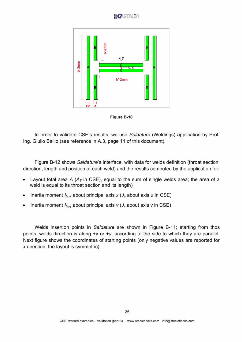
reported in next table. Fillet welds are named A, B and C according to Figure B-10.
Filled welds Length (Li)
A LA=b-2mm 298mm
B LB=b'-2mm 115.25mm
C LC=h'-2mm 223mm
25
CSE: worked examples – validation (part B) www.steelchecks.com [email protected]
Figure B-10
In order to validate CSE’s results, we use Saldature (Weldings) application by Prof.
Ing. Giulio Ballio (see reference in A.3, page 11 of this document).
Figure B-12 shows Saldature’s interface, with data for welds definition (throat section,
direction, length and position of each weld) and the results computed by the application for:
Layout total area A (AT in CSE), equal to the sum of single welds area; the area of a weld is equal to its throat section and its length)
Inertia moment IGxx about principal axis x (Ju about axis u in CSE)
Inertia moment IGyy about principal axis v (Jv about axis v in CSE)
Welds insertion points in Saldature are shown in Figure B-11; starting from thos
points, welds direction is along +x or +y, according to the side to which they are parallel.
Next figure shows the coordinates of starting points (only negative values are reported for
x direction, the layout is symmetric).

26
CSE: worked examples – validation (part B) www.steelchecks.com [email protected]
Figure B-11
Distances reported in Figure B-11
x1 -LC/2 -11.5mm
x2 -h/2+tf+a/2 -132.43mm
x3 -h/2-a/2 -167.07mm
y1 -tw/2-a/2 -12.821mm
y2 tw+r+1mm 33.75mm
y3 -LA/2 -149mm

27
CSE: worked examples – validation (part B) www.steelchecks.com [email protected]
Figure B-12 Layout area and inertia moments computed by Saldature
Results computed by Saldature are, given in mm4 and rounded to the fourth
significant digit:
A = 2.126*104mm2
IGxx = 1.251*108mm4
IGyy = 3.757*108mm4
The same values are computed by CSE:
-------------------------------------
Weldlayouts computational properties
-------------------------------------
Id xc yc beta AT Ju Jv Jp
W1 1.233e+001 4.559e+001 -7.070e-016 2.126e+004 1.251e+008 3.757e+008 5.008e+008
Polar inertia moment Jp is equal to the sum of Ju and Jv:

28
CSE: worked examples – validation (part B) www.steelchecks.com [email protected]
Jp = 1.251*108mm4 + 3.757*108mm4 = 5.008*108mm4
NOTES
xc and yc values printed in CSE’s output listing are the coordinates of layout centre
referred to insertion face clicked in the scene.
From version 4.1 on, CSE includes also penetration welds.

29
CSE: worked examples – validation (part B) www.steelchecks.com [email protected]
B.2 HORIZONTAL SPLICE JOINTS
B.2.1 Bolted cover plate
B.2.1.1 Introduction
We have a bolted cover plate splice joint with HEB300 cross-section (model
Validation_SP_1_1.CSE, Figure B-13). In Figure B-14 are reported the properties of the
shape used.
Figure B-13 3D view of the model
Figure B-14 Cross-section properties (units: mm, mm2, etc.)

30
CSE: worked examples – validation (part B) www.steelchecks.com [email protected]
Members and plates material is S235; bolts are M18 class 10.9 (fyb=900n/mm2,
fub=1000N/mm2). Next figures show different views of the model and of bolt layouts
schemes).
Figure B-15 Side view
Figure B-16 Top view

31
CSE: worked examples – validation (part B) www.steelchecks.com [email protected]
Figure B-17 Front view
Figure B-18 Upper flange bolts numbering (distances: 183mm, 50mm)

32
CSE: worked examples – validation (part B) www.steelchecks.com [email protected]
Figure B-19 Lower flange bolts numbering (distances: 183mm, 50mm)
Figure B-20 Web bolts numbering (distances: 49mm, 51mm)
Bolt layouts have the “shear only” option on: it means that a single layout is not
able to carry out of plate actions (bending and axial force), but in-plane actions only
(shear and torque, which produces shear in single bolts). If “shear only” layouts are
used for joints in bending, they must be properly positioned so that bending (or axial
forces) can be carried as shear forces in some layouts.
B.2.1.2 Bending about strong axis
B.2.1.2.1 Checks

33
CSE: worked examples – validation (part B) www.steelchecks.com [email protected]
In imported Sargon© model, constraints and loads are applied to get only a bending
moment in the node of the joint. The moment is equal to 1.2 times the plastic modulus of
the cross-section (overstrength factor). Moment is equal to 1.2*Wpl*fy = 5.27*108Nmm. For
the validation purpose, any other moment value could be used.
Note well: in early versions of the program, FEM model importing was the only way to
get geometry and internal forces. Now the same condition could be created defining the
node directly in CSE and defining the loads using amplified plastic limit of the member, a
defined value or an imported combination.
The following abstract report show the forces are distributed by CSE in each bolt
layout. Bending moment is carried as shear force by flanges bolt layouts (B1, B2, B3 and
B4) and a torque by web bolt layouts (B5 and B6). The most part of the load is carried by
flages bolt layouts.
--------------------------------------------------------------------
Forces acting over bolt layouts at different extremes, global system
--------------------------------------------------------------------
Id Inst Combi Ext Fx Fy Fz Mx My Mz
B3 1 1 1 -1.4745e-006 -1.5487e+006 1.9401e-006 -1.4170e+007 1.2367e-005 2.9493e-004
B3 1 1 2 1.4745e-006 1.5487e+006 -1.9401e-006 -1.6028e+007 1.6386e-005 -2.9493e-004
B1 1 1 1 -1.4745e-006 1.5487e+006 -1.9401e-006 1.4170e+007 1.2367e-005 2.9493e-004
B1 1 1 2 1.4745e-006 -1.5487e+006 1.9401e-006 1.6028e+007 1.6386e-005 -2.9493e-004
B2 1 1 1 1.4745e-006 1.5487e+006 1.7709e-006 1.4170e+007 -1.2367e-005 2.9493e-004
B2 1 1 2 -1.4745e-006 -1.5487e+006 -1.7709e-006 1.6028e+007 -1.6386e-005 -2.9493e-004
B4 1 1 1 1.4745e-006 -1.5487e+006 -1.7709e-006 -1.4170e+007 -1.2367e-005 2.9493e-004
B4 1 1 2 -1.4745e-006 1.5487e+006 1.7709e-006 -1.6028e+007 -1.6386e-005 -2.9493e-004
B5 1 1 1 -8.6227e-006 -5.7521e-004 -3.3269e-020 -3.7420e-003 4.9580e-005 2.9932e+007
B5 1 1 2 1.7245e-005 1.1113e-003 6.9568e-020 -1.4709e-004 8.4676e-017 -5.9864e+007
B5 1 1 3 -8.6227e-006 -5.3608e-004 -3.6300e-020 3.4390e-003 -4.9580e-005 2.9932e+007
B6 1 1 1 -8.6227e-006 6.6062e-004 -4.3419e-020 3.4390e-003 4.9580e-005 2.9932e+007
B6 1 1 2 1.7245e-005 -1.3865e-003 8.5367e-020 -4.4717e-004 1.1917e-016 -5.9864e+007
B6 1 1 3 -8.6227e-006 7.2584e-004 -4.1949e-020 -3.7420e-003 -4.9580e-005 2.9932e+007
Id bolt layout identification number
Inst joint instance
Combi load combination
Ext bolt layout extreme
Fx,y,z forces acting on bolt layout (axes x and y lie on layout plane)
Mx,y,z moments acting on bolt layout
Shear computed on flanges by CSE is 1.5487*106N; considering both flanges, total
carried moment is:
NmmNh
N 866 10646.42
30010547.12
210547.12
which is the 88% of total applied moment (5.27*108Nmm).

34
CSE: worked examples – validation (part B) www.steelchecks.com [email protected]
We can evaluate via hand computation the distribution of the forces in elastic range.
ywyftot fh
tfh
btM62
22
1
NmmmmNmm
mmmmNmm
mmmm 822
2 10205.4/2356
20811/235
2
300193002
Flanges carry the following moment
NmmmmNmm
mmmmfh
btM yff
82 10019.4/2352
300193002
22
which is the 95.6% del of total applied moment.
CSE assigns to flanges bolt layout a small moment, but this aspect must be
considered: forces distribution depends on flanges and web geometry but also on bolt
layouts translational stiffness (if there is not a bearing surface, it is proportional to bolt
numbers, bolt radius raised to the 4th power, and inversely proportional to cubed net
length; net length depends on number and thickness of bolted plates). Consider, for
example, to remove bolts on the web: obviously, the 100% of the load would be carried by
the flanges.
At the end of this paragraph, we will see how forces distribution changes when bolt
number on flanges changes, or when bolts diameter changes on flanges or web. It must be
underlined that each distribution which guarantees equilibrium is acceptable, according to
limit analysis theorem, if all the checks are done with coherence to assumed distribution.
The distribution computed by CSE (flexibility index was not change) is near to the one
we could find “by hand”. If the ratio web bolt layout / flanges bolt layout is greater than the
ratio web area / flanges area, web bolt layout will carry a greater load than that computed
considering areas only. The actual distribution is not so easy to be computed by hand.
In part C we will see how the flexibility index drives forces distribution. Flexibility index
is a parameter used to change translational stiffness of a bolt layout.
Let’s validate CSE results. Each bolt on the flanges should carry 1/14 of the total load
on the layout (since there are 14 bolts). We have 1.5487*106N / 14 = 1.106*105N.
--------------------------------------------------------------

35
CSE: worked examples – validation (part B) www.steelchecks.com [email protected]
Internal actions in bolts at different planes, exploitations
--------------------------------------------------------------
Inst Combi Name Bolt -?- NB NTB TuB TvB TB MuB MvB MB Expl cause
1 1 B3 1 1 1.386e-007 1.386e-007 6.667e-008 -1.106e+005 1.106e+005 9.401e+004 -1.699e-007 9.401e+004 0.906 resis
1 1 B3 2 1 1.386e-007 1.386e-007 6.667e-008 -1.106e+005 1.106e+005 9.401e+004 -1.699e-007 9.401e+004 0.906 resis
1 1 B3 3 1 1.386e-007 1.386e-007 9.341e-009 -1.106e+005 1.106e+005 9.401e+004 -1.699e-007 9.401e+004 0.906 resis
1 1 B3 4 1 1.386e-007 1.386e-007 9.341e-009 -1.106e+005 1.106e+005 9.401e+004 -1.699e-007 9.401e+004 0.906 resis
1 1 B3 5 1 1.386e-007 1.386e-007 -4.799e-008 -1.106e+005 1.106e+005 9.401e+004 -1.699e-007 9.401e+004 0.906 resis
1 1 B3 6 1 1.386e-007 1.386e-007 -4.799e-008 -1.106e+005 1.106e+005 9.401e+004 -1.699e-007 9.401e+004 0.906 resis
1 1 B3 7 1 1.386e-007 1.386e-007 -1.053e-007 -1.106e+005 1.106e+005 9.401e+004 -1.699e-007 9.401e+004 0.906 resis
1 1 B3 8 1 1.386e-007 1.386e-007 -1.053e-007 -1.106e+005 1.106e+005 9.401e+004 -1.699e-007 9.401e+004 0.906 resis
1 1 B3 9 1 1.386e-007 1.386e-007 -1.627e-007 -1.106e+005 1.106e+005 9.401e+004 -1.699e-007 9.401e+004 0.906 resis
1 1 B3 10 1 1.386e-007 1.386e-007 -1.627e-007 -1.106e+005 1.106e+005 9.401e+004 -1.699e-007 9.401e+004 0.906 resis
1 1 B3 11 1 1.386e-007 1.386e-007 -2.200e-007 -1.106e+005 1.106e+005 9.401e+004 -1.699e-007 9.401e+004 0.906 resis
1 1 B3 12 1 1.386e-007 1.386e-007 -2.200e-007 -1.106e+005 1.106e+005 9.401e+004 -1.699e-007 9.401e+004 0.906 resis
1 1 B3 13 1 1.386e-007 1.386e-007 -2.773e-007 -1.106e+005 1.106e+005 9.401e+004 -1.699e-007 9.401e+004 0.906 resis
1 1 B3 14 1 1.386e-007 1.386e-007 -2.773e-007 -1.106e+005 1.106e+005 9.401e+004 -1.699e-007 9.401e+004 0.906 resis
1 1 B1 1 1 -1.386e-007 -1.386e-007 6.667e-008 1.106e+005 1.106e+005 -9.401e+004 -1.699e-007 9.401e+004 0.906 resis
1 1 B1 2 1 -1.386e-007 -1.386e-007 6.667e-008 1.106e+005 1.106e+005 -9.401e+004 -1.699e-007 9.401e+004 0.906 resis
1 1 B1 3 1 -1.386e-007 -1.386e-007 9.340e-009 1.106e+005 1.106e+005 -9.401e+004 -1.699e-007 9.401e+004 0.906 resis
1 1 B1 4 1 -1.386e-007 -1.386e-007 9.340e-009 1.106e+005 1.106e+005 -9.401e+004 -1.699e-007 9.401e+004 0.906 resis
1 1 B1 5 1 -1.386e-007 -1.386e-007 -4.799e-008 1.106e+005 1.106e+005 -9.401e+004 -1.699e-007 9.401e+004 0.906 resis
1 1 B1 6 1 -1.386e-007 -1.386e-007 -4.799e-008 1.106e+005 1.106e+005 -9.401e+004 -1.699e-007 9.401e+004 0.906 resis
1 1 B1 7 1 -1.386e-007 -1.386e-007 -1.053e-007 1.106e+005 1.106e+005 -9.401e+004 -1.699e-007 9.401e+004 0.906 resis
1 1 B1 8 1 -1.386e-007 -1.386e-007 -1.053e-007 1.106e+005 1.106e+005 -9.401e+004 -1.699e-007 9.401e+004 0.906 resis
1 1 B1 9 1 -1.386e-007 -1.386e-007 -1.627e-007 1.106e+005 1.106e+005 -9.401e+004 -1.699e-007 9.401e+004 0.906 resis
1 1 B1 10 1 -1.386e-007 -1.386e-007 -1.627e-007 1.106e+005 1.106e+005 -9.401e+004 -1.699e-007 9.401e+004 0.906 resis
1 1 B1 11 1 -1.386e-007 -1.386e-007 -2.200e-007 1.106e+005 1.106e+005 -9.401e+004 -1.699e-007 9.401e+004 0.906 resis
1 1 B1 12 1 -1.386e-007 -1.386e-007 -2.200e-007 1.106e+005 1.106e+005 -9.401e+004 -1.699e-007 9.401e+004 0.906 resis
1 1 B1 13 1 -1.386e-007 -1.386e-007 -2.773e-007 1.106e+005 1.106e+005 -9.401e+004 -1.699e-007 9.401e+004 0.906 resis
1 1 B1 14 1 -1.386e-007 -1.386e-007 -2.773e-007 1.106e+005 1.106e+005 -9.401e+004 -1.699e-007 9.401e+004 0.906 resis
1 1 B2 1 1 1.265e-007 1.265e-007 2.773e-007 1.106e+005 1.106e+005 -9.401e+004 1.699e-007 9.401e+004 0.906 resis
1 1 B2 2 1 1.265e-007 1.265e-007 2.773e-007 1.106e+005 1.106e+005 -9.401e+004 1.699e-007 9.401e+004 0.906 resis
1 1 B2 3 1 1.265e-007 1.265e-007 2.200e-007 1.106e+005 1.106e+005 -9.401e+004 1.699e-007 9.401e+004 0.906 resis
1 1 B2 4 1 1.265e-007 1.265e-007 2.200e-007 1.106e+005 1.106e+005 -9.401e+004 1.699e-007 9.401e+004 0.906 resis
1 1 B2 5 1 1.265e-007 1.265e-007 1.627e-007 1.106e+005 1.106e+005 -9.401e+004 1.699e-007 9.401e+004 0.906 resis
1 1 B2 6 1 1.265e-007 1.265e-007 1.627e-007 1.106e+005 1.106e+005 -9.401e+004 1.699e-007 9.401e+004 0.906 resis
1 1 B2 7 1 1.265e-007 1.265e-007 1.053e-007 1.106e+005 1.106e+005 -9.401e+004 1.699e-007 9.401e+004 0.906 resis
1 1 B2 8 1 1.265e-007 1.265e-007 1.053e-007 1.106e+005 1.106e+005 -9.401e+004 1.699e-007 9.401e+004 0.906 resis
1 1 B2 9 1 1.265e-007 1.265e-007 4.799e-008 1.106e+005 1.106e+005 -9.401e+004 1.699e-007 9.401e+004 0.906 resis
1 1 B2 10 1 1.265e-007 1.265e-007 4.799e-008 1.106e+005 1.106e+005 -9.401e+004 1.699e-007 9.401e+004 0.906 resis
1 1 B2 11 1 1.265e-007 1.265e-007 -9.340e-009 1.106e+005 1.106e+005 -9.401e+004 1.699e-007 9.401e+004 0.906 resis
1 1 B2 12 1 1.265e-007 1.265e-007 -9.340e-009 1.106e+005 1.106e+005 -9.401e+004 1.699e-007 9.401e+004 0.906 resis
1 1 B2 13 1 1.265e-007 1.265e-007 -6.667e-008 1.106e+005 1.106e+005 -9.401e+004 1.699e-007 9.401e+004 0.906 resis
1 1 B2 14 1 1.265e-007 1.265e-007 -6.667e-008 1.106e+005 1.106e+005 -9.401e+004 1.699e-007 9.401e+004 0.906 resis
1 1 B4 1 1 -1.265e-007 -1.265e-007 2.773e-007 -1.106e+005 1.106e+005 9.401e+004 1.699e-007 9.401e+004 0.906 resis
1 1 B4 2 1 -1.265e-007 -1.265e-007 2.773e-007 -1.106e+005 1.106e+005 9.401e+004 1.699e-007 9.401e+004 0.906 resis
1 1 B4 3 1 -1.265e-007 -1.265e-007 2.200e-007 -1.106e+005 1.106e+005 9.401e+004 1.699e-007 9.401e+004 0.906 resis
1 1 B4 4 1 -1.265e-007 -1.265e-007 2.200e-007 -1.106e+005 1.106e+005 9.401e+004 1.699e-007 9.401e+004 0.906 resis
1 1 B4 5 1 -1.265e-007 -1.265e-007 1.627e-007 -1.106e+005 1.106e+005 9.401e+004 1.699e-007 9.401e+004 0.906 resis
1 1 B4 6 1 -1.265e-007 -1.265e-007 1.627e-007 -1.106e+005 1.106e+005 9.401e+004 1.699e-007 9.401e+004 0.906 resis
1 1 B4 7 1 -1.265e-007 -1.265e-007 1.053e-007 -1.106e+005 1.106e+005 9.401e+004 1.699e-007 9.401e+004 0.906 resis
1 1 B4 8 1 -1.265e-007 -1.265e-007 1.053e-007 -1.106e+005 1.106e+005 9.401e+004 1.699e-007 9.401e+004 0.906 resis
1 1 B4 9 1 -1.265e-007 -1.265e-007 4.799e-008 -1.106e+005 1.106e+005 9.401e+004 1.699e-007 9.401e+004 0.906 resis
1 1 B4 10 1 -1.265e-007 -1.265e-007 4.799e-008 -1.106e+005 1.106e+005 9.401e+004 1.699e-007 9.401e+004 0.906 resis
1 1 B4 11 1 -1.265e-007 -1.265e-007 -9.340e-009 -1.106e+005 1.106e+005 9.401e+004 1.699e-007 9.401e+004 0.906 resis
1 1 B4 12 1 -1.265e-007 -1.265e-007 -9.340e-009 -1.106e+005 1.106e+005 9.401e+004 1.699e-007 9.401e+004 0.906 resis
1 1 B4 13 1 -1.265e-007 -1.265e-007 -6.667e-008 -1.106e+005 1.106e+005 9.401e+004 1.699e-007 9.401e+004 0.906 resis
1 1 B4 14 1 -1.265e-007 -1.265e-007 -6.667e-008 -1.106e+005 1.106e+005 9.401e+004 1.699e-007 9.401e+004 0.906 resis
1 1 B5 1 1 -5.545e-021 -5.545e-021 1.090e+005 -5.236e+004 1.209e+005 -4.845e-005 -3.593e-007 4.845e-005 0.990 resis
1 1 B5 1 2 6.050e-021 6.050e-021 -1.090e+005 5.236e+004 1.209e+005 -3.710e-005 -3.593e-007 3.710e-005 0.990
1 1 B5 2 1 -5.545e-021 -5.545e-021 1.090e+005 5.236e+004 1.209e+005 -4.845e-005 -3.593e-007 4.845e-005 0.990 resis
1 1 B5 2 2 6.050e-021 6.050e-021 -1.090e+005 -5.236e+004 1.209e+005 -3.710e-005 -3.593e-007 3.710e-005 0.990
1 1 B5 3 1 -5.545e-021 -5.545e-021 -1.437e-006 -5.236e+004 5.236e+004 -4.845e-005 -3.593e-007 4.845e-005 0.429 resis
1 1 B5 3 2 6.050e-021 6.050e-021 1.437e-006 5.236e+004 5.236e+004 -3.710e-005 -3.593e-007 3.710e-005 0.429
1 1 B5 4 1 -5.545e-021 -5.545e-021 -1.437e-006 5.236e+004 5.236e+004 -4.845e-005 -3.593e-007 4.845e-005 0.429
1 1 B5 4 2 6.050e-021 6.050e-021 1.437e-006 -5.236e+004 5.236e+004 -3.710e-005 -3.593e-007 3.710e-005 0.429 resis
1 1 B5 5 1 -5.545e-021 -5.545e-021 -1.090e+005 -5.236e+004 1.209e+005 -4.845e-005 -3.593e-007 4.845e-005 0.990 resis
1 1 B5 5 2 6.050e-021 6.050e-021 1.090e+005 5.236e+004 1.209e+005 -3.710e-005 -3.593e-007 3.710e-005 0.990
1 1 B5 6 1 -5.545e-021 -5.545e-021 -1.090e+005 5.236e+004 1.209e+005 -4.845e-005 -3.593e-007 4.845e-005 0.990 resis
1 1 B5 6 2 6.050e-021 6.050e-021 1.090e+005 -5.236e+004 1.209e+005 -3.710e-005 -3.593e-007 3.710e-005 0.990
1 1 B6 1 1 -7.236e-021 -7.236e-021 1.090e+005 -5.236e+004 1.209e+005 -8.744e-005 -3.593e-007 8.744e-005 0.990 resis
1 1 B6 1 2 6.991e-021 6.991e-021 -1.090e+005 5.236e+004 1.209e+005 -1.022e-004 -3.593e-007 1.022e-004 0.990
1 1 B6 2 1 -7.236e-021 -7.236e-021 1.090e+005 5.236e+004 1.209e+005 -8.744e-005 -3.593e-007 8.744e-005 0.990 resis
1 1 B6 2 2 6.991e-021 6.991e-021 -1.090e+005 -5.236e+004 1.209e+005 -1.022e-004 -3.593e-007 1.022e-004 0.990
1 1 B6 3 1 -7.236e-021 -7.236e-021 -1.437e-006 -5.236e+004 5.236e+004 -8.744e-005 -3.593e-007 8.744e-005 0.429 resis
1 1 B6 3 2 6.991e-021 6.991e-021 1.437e-006 5.236e+004 5.236e+004 -1.022e-004 -3.593e-007 1.022e-004 0.429
1 1 B6 4 1 -7.236e-021 -7.236e-021 -1.437e-006 5.236e+004 5.236e+004 -8.744e-005 -3.593e-007 8.744e-005 0.429
1 1 B6 4 2 6.991e-021 6.991e-021 1.437e-006 -5.236e+004 5.236e+004 -1.022e-004 -3.593e-007 1.022e-004 0.429 resis
1 1 B6 5 1 -7.236e-021 -7.236e-021 -1.090e+005 -5.236e+004 1.209e+005 -8.744e-005 -3.593e-007 8.744e-005 0.990 resis
1 1 B6 5 2 6.991e-021 6.991e-021 1.090e+005 5.236e+004 1.209e+005 -1.022e-004 -3.593e-007 1.022e-004 0.990
1 1 B6 6 1 -7.236e-021 -7.236e-021 -1.090e+005 5.236e+004 1.209e+005 -8.744e-005 -3.593e-007 8.744e-005 0.990 resis
1 1 B6 6 2 6.991e-021 6.991e-021 1.090e+005 -5.236e+004 1.209e+005 -1.022e-004 -3.593e-007 1.022e-004 0.990
Bolt: number of bolt (from 1 to n for each layout)
Sec: check section (number of drilled plates less 1)
NB, TuB, TvB, MuB, MvB: axial force, shear and moments in each check section
NTB: total axial force (including preload)
TB: sum of Tu and Tv

36
CSE: worked examples – validation (part B) www.steelchecks.com [email protected]
MB: sum of Mu and Mv
expl: utilization factor according to the Standard (EN1993-1-8 in this case)
NOTE WELL: CSE computes also the parasitic bending in bolt shafts: this can be
considered or neglected in the checks.
Utilization factor, neglecting axial force in the bolt (it is quite null) is the ratio between
shear force in the bolt (FV,Ed) and design resistance (FV,Rd):
2
,
M
ubvRdv
AfF
M2 is equal to 1.25; resisting area for shear is the total one; v=0.6 (see following abstract
from EN 1993-1-8: 2005).
All the bolts are equal, so they have the same design resistance:
NF Rdv
5
, 10221.125.1
5.25410006.0
CSE computes the following data, that are the same:
----------------------------
Boltlayouts bolt properties
----------------------------
Id Class Dia Dia H Sec Full Precision Area Ares Vlim Nlim Nini
B3 10.9 18.0 20.0 1 yes not 2.545e+002 1.920e+002 1.221e+005 1.382e+005 0.000e+000
B1 10.9 18.0 20.0 1 yes not 2.545e+002 1.920e+002 1.221e+005 1.382e+005 0.000e+000
B2 10.9 18.0 20.0 1 yes not 2.545e+002 1.920e+002 1.221e+005 1.382e+005 0.000e+000
B4 10.9 18.0 20.0 1 yes not 2.545e+002 1.920e+002 1.221e+005 1.382e+005 0.000e+000
B5 10.9 18.0 20.0 2 yes not 2.545e+002 1.920e+002 1.221e+005 1.382e+005 0.000e+000
B6 10.9 18.0 20.0 2 yes not 2.545e+002 1.920e+002 1.221e+005 1.382e+005 0.000e+000

37
CSE: worked examples – validation (part B) www.steelchecks.com [email protected]
Figure B-21 Abstract from EN 1993-1-8: 2005: bolts design resistance
Bolts of layouts B1, B2, B3 and B4 are subject to the same force, equal to
1.106E+05N; utilization facto is equal to:
906.010221.1
10106.15
5
,
,
N
N
F
F
RdV
EdV
--------------------------------------------------------------
Internal actions in bolts at different planes, exploitations
--------------------------------------------------------------
Inst Combi Name Bolt -?- NB NTB TuB TvB TB MuB MvB MB Expl cause
1 1 B1 4 1 -1.386e-007 -1.386e-007 9.340e-009 1.106e+005 1.106e+005 -9.401e+004 -1.699e-007 9.401e+004 0.906 resis
Consider now the forces acting on web bolt layouts. The torque computed by CSE
(equal to -5.9864x10⁷Nmm) is distributed in two check sections, loaded with the half of that
moment. Internal force on each bolt depends on the distance from each bolt to the centre,
considering an elastic distribution.
dJ
MT
p
tb
2/

38
CSE: worked examples – validation (part B) www.steelchecks.com [email protected]
Figure B-22
Jp is bolt layout polar inertia moment; with the distances printed in next figure, we have:
Jp = 4 * 56.62 + 2 * 24.52 = 1.401*104mm2
Figure B-23
Shear is equal to:
Nmmmm
NmmTb
4
24
7
10234.55.2410401.1
2/105.986
for central bolts
Nmmmm
NmmTb
5
24
7
10209.16.5610401.1
2/105.986
for external bolts
These forces are the same computed by CSE:
--------------------------------------------------------------
Internal actions in bolts at different planes, exploitations
--------------------------------------------------------------
Inst Combi Name Bolt -?- NB NTB TuB TvB TB MuB MvB MB Expl cause
1 1 B5 1 1 -5.545e-021 -5.545e-021 1.090e+005 -5.236e+004 1.209e+005 -4.845e-005 -3.593e-007 4.845e-005 0.990 resis
1 1 B5 1 2 6.050e-021 6.050e-021 -1.090e+005 5.236e+004 1.209e+005 -3.710e-005 -3.593e-007 3.710e-005 0.990
1 1 B5 2 1 -5.545e-021 -5.545e-021 1.090e+005 5.236e+004 1.209e+005 -4.845e-005 -3.593e-007 4.845e-005 0.990 resis
1 1 B5 2 2 6.050e-021 6.050e-021 -1.090e+005 -5.236e+004 1.209e+005 -3.710e-005 -3.593e-007 3.710e-005 0.990
1 1 B5 3 1 -5.545e-021 -5.545e-021 -1.437e-006 -5.236e+004 5.236e+004 -4.845e-005 -3.593e-007 4.845e-005 0.429 resis
1 1 B5 3 2 6.050e-021 6.050e-021 1.437e-006 5.236e+004 5.236e+004 -3.710e-005 -3.593e-007 3.710e-005 0.429
1 1 B5 4 1 -5.545e-021 -5.545e-021 -1.437e-006 5.236e+004 5.236e+004 -4.845e-005 -3.593e-007 4.845e-005 0.429
1 1 B5 4 2 6.050e-021 6.050e-021 1.437e-006 -5.236e+004 5.236e+004 -3.710e-005 -3.593e-007 3.710e-005 0.429 resis
1 1 B5 5 1 -5.545e-021 -5.545e-021 -1.090e+005 -5.236e+004 1.209e+005 -4.845e-005 -3.593e-007 4.845e-005 0.990 resis

39
CSE: worked examples – validation (part B) www.steelchecks.com [email protected]
1 1 B5 5 2 6.050e-021 6.050e-021 1.090e+005 5.236e+004 1.209e+005 -3.710e-005 -3.593e-007 3.710e-005 0.990
1 1 B5 6 1 -5.545e-021 -5.545e-021 -1.090e+005 5.236e+004 1.209e+005 -4.845e-005 -3.593e-007 4.845e-005 0.990 resis
1 1 B5 6 2 6.050e-021 6.050e-021 1.090e+005 -5.236e+004 1.209e+005 -3.710e-005 -3.593e-007 3.710e-005 0.990
1 1 B6 1 1 -7.236e-021 -7.236e-021 1.090e+005 -5.236e+004 1.209e+005 -8.744e-005 -3.593e-007 8.744e-005 0.990 resis
1 1 B6 1 2 6.991e-021 6.991e-021 -1.090e+005 5.236e+004 1.209e+005 -1.022e-004 -3.593e-007 1.022e-004 0.990
1 1 B6 2 1 -7.236e-021 -7.236e-021 1.090e+005 5.236e+004 1.209e+005 -8.744e-005 -3.593e-007 8.744e-005 0.990 resis
1 1 B6 2 2 6.991e-021 6.991e-021 -1.090e+005 -5.236e+004 1.209e+005 -1.022e-004 -3.593e-007 1.022e-004 0.990
1 1 B6 3 1 -7.236e-021 -7.236e-021 -1.437e-006 -5.236e+004 5.236e+004 -8.744e-005 -3.593e-007 8.744e-005 0.429 resis
1 1 B6 3 2 6.991e-021 6.991e-021 1.437e-006 5.236e+004 5.236e+004 -1.022e-004 -3.593e-007 1.022e-004 0.429
1 1 B6 4 1 -7.236e-021 -7.236e-021 -1.437e-006 5.236e+004 5.236e+004 -8.744e-005 -3.593e-007 8.744e-005 0.429
1 1 B6 4 2 6.991e-021 6.991e-021 1.437e-006 -5.236e+004 5.236e+004 -1.022e-004 -3.593e-007 1.022e-004 0.429 resis
1 1 B6 5 1 -7.236e-021 -7.236e-021 -1.090e+005 -5.236e+004 1.209e+005 -8.744e-005 -3.593e-007 8.744e-005 0.990 resis
1 1 B6 5 2 6.991e-021 6.991e-021 1.090e+005 5.236e+004 1.209e+005 -1.022e-004 -3.593e-007 1.022e-004 0.990
1 1 B6 6 1 -7.236e-021 -7.236e-021 -1.090e+005 5.236e+004 1.209e+005 -8.744e-005 -3.593e-007 8.744e-005 0.990 resis
1 1 B6 6 2 6.991e-021 6.991e-021 1.090e+005 -5.236e+004 1.209e+005 -1.022e-004 -3.593e-007 1.022e-004 0.990
Consider, for example, bolt number 3 of layout B5. Its utilization factor is
5.234*104N/1.221*105N=0.429, as computed by CSE.
Now consider bolt bearing. The check according to EN1993-1-8 is given by the
following formula.
Figure B-24 Abstract from EN 1993-1-8: 2005: design resistance for bolt bearing
Distances e1, e2, p1 and p2 are defined in the following schemes.

40
CSE: worked examples – validation (part B) www.steelchecks.com [email protected]
Figure B-25 Abstract from EN 1993-1-8: 2005: distances e1, e2, p1, p2
NOTE WELL: bolts are classified inner or end/edge according to their position depending
on load direction (parallel to one of the sides). If a force is not parallel to any side, it must
be divided in its parallel and normal components.
The Standard states to apply the check in the two directions separately. This does not
seem on the safe side, so CSE gives an utilization factor equal to the square root of the
sum of the square of the two partial utilizations.
In addition, the Standard does not consider situations with different plate shapes, with
non-parallel edges (for example circular plates, see next figure), of members cut with an
inclined plate, etc. To be always on the safe side, CSE uses minimum distance from the
edge of each drilled object.
Figure B-26
Bolt bearing check requires a long computation for each bolt. Let’s consider just one
bolt and validate it accurately. For example, we can choose one of most loaded bolts (for
web layout they are upper and lower bolts) and considering the effect on member’s web.

41
CSE: worked examples – validation (part B) www.steelchecks.com [email protected]
The force applied by the bolts to the web is the reaction to the torque in bolt layout
central section. In this symmetrical case, forces on web are twice the forces in bolts check
sections; they are:
Nmmmm
Nmmd
J
MF
p
tx
5
24
7
10179.25110401.1
105.986
Nmmmm
Nmmd
J
MF
p
ty
5
24
7
10047.15.2410401.1
105.986
According to the formulae in Figure B-25, next table contains the data for bolt bearing
resistance in the two directions; distances are given in next figure.
Figure B-27 Web bolt layout: distances between bolts and from edges
Fx 2,179E+05 Fy 1,047E+05
Fb,Rd,x 6,043E+04 Fb,Rd,y 5,919E+04
k1 1,87 k1 1,73
2,8e2/d0-1,7 5,23 2,8e2/d0-1,7 5,23
1,4p2/d0-1,7 1,87 1,4p2/d0-1,7 1,73
2,5
2,5
ab 0,566666667 ab 0,600
ad 0,825 ad 0,825
fub/fu 2,78 fub/fu 2,78
p1/3d0-0,25 0,57 p1/3d0-0,25 0,60
1
1
fu 360 fu 360
d 18 d 18
d0 20 d0 20
t 11 t 11
e1=min(e1,e2) 49,5 e1=min(e1,e2) 49,5
e2=min(e1,e2) 49,5 e2=min(e1,e2) 49,5
p1 49 p1 51

42
CSE: worked examples – validation (part B) www.steelchecks.com [email protected]
p2 51 p2 49
expl x 3,606 expl y 1,769
EXPL= 4,017
To be on the safe side, e1 and e2 are assumed equal to minimum between e1 and e2
Let’s compute Fb,Rd,x and Fb,Rd,y step by step, and then the utilization factor.
2
1,,
M
ubxRdb
dtfkF
)0.1 ; ;min(u
ubdb
f
f
78.2/360
/1000
2
2
mmN
mmN
f
f
u
ub
boltsendformm
mm
mm
mm
d
p
d
ed 57.0}25,0
203
49,
203
5.49min()25,0
3;
3min{
0
1
0
1
57.0 db
bolts edgeor )5.2 ;7.14.1 ;7.18.2min(0
2
0
21 f
d
p
d
ek
5.223.57.120
5.498.27.18.2
0
2 mm
mm
d
e
87,17.14.10
2 d
p
87.11 k
NmmmmmmNdtfk
FM
ubxRdb
52
2
1,, 106043.0
25.1
1118/36057.087.1
606.31060.0
10179.2expl
5
5
,,
x
N
N
F
F
xRdb
x
2
1,,
M
ubyRdb
dtfkF
)0.1 ; ;min(u
ubdb
f
f
78.2/360
/1000
2
2
mmN
mmN
f
f
u
ub
boltsendformm
mm
mm
mm
d
p
d
ed 60.0}25,0
203
51,
203
5.49min()25,0
3;
3min{
0
1
0
1
boltsendformm
mm
d
ed 60.0
203
5.49
3 0
1

43
CSE: worked examples – validation (part B) www.steelchecks.com [email protected]
60.0 db
bolts edgeor )5.2 ;7.14.1 ;7.18.2min(0
2
0
21 f
d
p
d
ek
5.223.57.120
5.498.27.18.2
0
2 mm
mm
d
e
73,17.14.10
2 d
p
73.11 k
NmmmmmmNdtfk
FM
ubyRdb
52
2
1,, 105919.0
25.1
1118/360600.073.1
769.11059.0
10047.1expl
5
5
,,
y
N
N
F
F
yRdb
y
Total utilization is:
017.4explexplexpl 2
y
2
x
Maximum value computed by CSE is the same, because we have chosen the most
loaded bolt. A complete check by hand would require the previous computations for each
bolt of the web and for each bolt of the flanges, considering applied forces, distances
between bolts and distances from edges every time different.
------------------------------------------------------------------
Members whose maximum utilization ratio is due to bearing stresses
------------------------------------------------------------------
Inst Combi Name Boltlay Bolt Extr. Sigma Sigma M Expl
( N/ mm²) ( N/ mm²)
1 1 m1 B5 1 2 1221.4 304.0 4.018 !!!
1 1 m2 B6 2 2 1221.4 304.0 4.018 !!!
NOTE WELL: Sigma M (max) value printed in the listing is computed dividing
utilization factor by sigma: the value is referred to current force direction. If force direction
changes, limit value changes as well.
Here we have a very high utilization, but the scope is to validate CSE results, not to
design a proper joint.

44
CSE: worked examples – validation (part B) www.steelchecks.com [email protected]
Figure B-28 Utilization of the components according to EN 1993-1-8: 2005
B.2.1.2.2 How bolt layout stiffness rules forces distribution
The translational stiffness of a bolt layout is proportional to:
Bolts number (nb)
Bolts radius raised to the 4th power (rb4)
It is inversely proportional to:
Cubed bolts net length (l)
The flexibility index will be introduced in part C: this index can be used to modify the
translational stiffness of a layout. Here the stiffness is modified by changing bolts diameter
or number.
Some modifications have been done to the original model, in order to see how CSE
computes, in different conditions, he distribution of forces flanges bolt layouts (Vf). Total
applied moment (Mtot) is compared to the part carried by flanges bolt layout (Mf):
Mf / Mtot
Mf is equal to:

45
CSE: worked examples – validation (part B) www.steelchecks.com [email protected]
Mf = 2 * Vf * h/2 = 2 * Vf * 150 = Vf * 300
where Vf is the shear carried by flanges bolt layout, as computed by CSE, h/2 is the lever
arm of the shear (half of the height of HEB300 shape) and 2 is the number of layouts on
the flanges (upper and lower).
1) Modification of bolts number on flanges; web bolt layouts not modified (models:
Validation_SP_1_1_001.CSE Validation_SP_1_1_006.CSE)
Web bolt layouts are unchanged. On the flanges, starting from original configuration
(7 rows / 2 columns) we remove a row (6 rows), and so on until last condition (2 rows).
These are the results according to shears computed by CSE in flanges bolt layouts (with
two rows only, the 69% of applied load is carried by the flanges).
0,0
0,2
0,4
0,6
0,8
1,0
1,2
1 2 3 4 5 6 7 8
rows of bolts on flanges
Mf / M
tot
varying bolt rows on flanges
Total applied moment
2) Modification of bolts diameter on flanges; web bolt layouts not modified

46
CSE: worked examples – validation (part B) www.steelchecks.com [email protected]
Starting from original model, we reduce flange bolts diameter: M18, M16, M14, M12,
M10, M8. When bolts diameter decreases, the load carried by the flanges decreases too.
With M8 bolts, flanges carry only the 39% of the applied load.
0,0
0,2
0,4
0,6
0,8
1,0
1,2
7 8 9 10 11 12 13 14 15 16 17 18 19
flanges bolts diameter [mm]
Mf / M
tot
varying diameter on flanges
total applied moment
3) Modification of bolts diameter on web; flanges bolt layouts not modified
In this case, we reduce web bolts diameter: the load carried by the flanges increases.
Using M8 bolts on the web, quite the total load (97%) is carried by the flanges, since web
bolt layout stiffness is reduced.

47
CSE: worked examples – validation (part B) www.steelchecks.com [email protected]
0,0
0,2
0,4
0,6
0,8
1,0
1,2
7 8 9 10 11 12 13 14 15 16 17 18 19
web bolts diameter [mm]
Mf / M
tot
varying diameter on web
total applied moment
These results show that forces distribution computed by CSE does not depend on
cross-section geometry only, but it depends also on bolt layouts stiffness ratio.
Figure B-29 Dialog box: bolt layout modification

48
CSE: worked examples – validation (part B) www.steelchecks.com [email protected]
Figure B-30 Dialog box: bolts diameter modification
B.2.1.3 Shear parallel to the web
Constraints and loads were modified in a copy of the model used previously, in order
to have only a shear parallel to web in joint node (new model name
Validation_SP_1_2.CSE). Shear value is the plastic limit of the member with overstrength
factor 1.2:
NfA
VVyv
RDplRD 7722213
2.1,
with fy = 235N/mm2 and
2474322 mmtrtbtAA fwfv
3D real joint has the same geometry and properties of the one shown in B.2.1. In
CSE computation, the almost the whole load is carried by web bolt layout.
--------------------------------------------------------------------

49
CSE: worked examples – validation (part B) www.steelchecks.com [email protected]
Forces acting over bolt layouts at different extremes, global system
--------------------------------------------------------------------
Id Inst Combi Ext Fx Fy Fz Mx My Mz
B3 1 1 1 1.8062e-006 -3.4619e-004 1.4133e+001 2.8267e+003 -1.5149e-005 -3.6124e-004
B3 1 1 2 -1.8062e-006 3.4619e-004 -1.4133e+001 -2.8267e+003 -2.0072e-005 3.6124e-004
B1 1 1 1 1.8062e-006 3.4629e-004 -1.4133e+001 -2.8267e+003 -1.5149e-005 -3.6124e-004
B1 1 1 2 -1.8062e-006 -3.4629e-004 1.4133e+001 2.8267e+003 -2.0072e-005 3.6124e-004
B2 1 1 1 -1.8062e-006 3.4619e-004 -1.4134e+001 2.8267e+003 1.5149e-005 -3.6124e-004
B2 1 1 2 1.8062e-006 -3.4619e-004 1.4134e+001 -2.8267e+003 2.0072e-005 3.6124e-004
B4 1 1 1 -1.8062e-006 -3.4629e-004 1.4134e+001 -2.8267e+003 1.5149e-005 -3.6124e-004
B4 1 1 2 1.8062e-006 3.4629e-004 -1.4134e+001 2.8267e+003 2.0072e-005 3.6124e-004
B5 1 1 1 4.7923e-008 -3.8610e+005 -2.4005e-011 -2.2201e+006 -2.7556e-007 -2.8571e+007
B5 1 1 2 -9.5845e-008 7.7219e+005 4.8009e-011 -2.1144e-005 2.1165e-017 5.7142e+007
B5 1 1 3 4.7923e-008 -3.8610e+005 -2.4005e-011 2.2201e+006 2.7556e-007 -2.8571e+007
B6 1 1 1 4.7923e-008 3.8610e+005 -2.3641e-011 2.2201e+006 -2.7556e-007 2.8571e+007
B6 1 1 2 -9.5845e-008 -7.7219e+005 4.7282e-011 5.4767e-004 -2.1861e-017 -5.7142e+007
B6 1 1 3 4.7923e-008 3.8610e+005 -2.3641e-011 -2.2201e+006 2.7556e-007 2.8571e+007
Shear carried by web bolt layouts (B5 and B6, section number 2, the central one) is
772190N; total load is 772221N. A very small part is carried by flanges bolt layout (via a
bending moment in bolts shafts, as we will see later). Note well: all bolts layouts in this
model are “shear only”.
The shear applied to member extreme produces an equal shear applied to bolt layout
centre. In addition, there is a moment of transport equal to:
M’ = T * b = 772190N * 74mm = 5.714*107Nmm.
Figure B-31
Shear force acting on each bolt is the sum of two components:
1. total shear divided by bolts number (V/6)
2. shear due to torque (M’) on the layout

50
CSE: worked examples – validation (part B) www.steelchecks.com [email protected]
For the second components, force in the bolts depends on their distance from the
centre. First contribution is shown on the left in next figure; in the middle there is the
second contribution, on the right the sum of them.
Figure B-32
Resulting shear force is higher on bolts were the components have the same
direction. Now we are going to compute those values, and then we’ll compare them with
CSE values. The following formula defines the resultant force on each bolt:
2
)( 2
,,
2
,,, xiMyiMiV
i
VVVR
where
Ri is the resultant force on each bolt.
VV,i is the force due to total shear divided by bolts number: VV,i=V/6=1.287e+05N
VM,i is the component due to moment of transport M’ (it is divided into x-direction and y-
direction forces).
Polar inertia moment of the layout is equal to
Jp = 4 * 56.62 + 2 * 24.52 = 1.401*104mm2
According to distances shown in Figure B-27, we have:
Nmmmm
Nd
J
MV yi
p
xiM
5
24
7
,,, 10080.25110401.1
10714.5'
Nmmmm
Nmmd
J
MV xi
p
yiM
4
24
7
,,, 10993.95.2410401.1
10714.5'

51
CSE: worked examples – validation (part B) www.steelchecks.com [email protected]
For central bolts (d=24.5mm) VMi,x is null and VMi,y is 9.993e+04N. Last value must be
added to V/6 on one bolt and subtracted from the other. Since we have two different check
sections, resultant forces must be divided by 2. It results:
(V/6 + VMi,y) / 2 = (1.287*105N + 9.9927*104N) / 2 = 1.143*105N
(V/6 - VMi,y) / 2 = (1.287*105N – 9.9927*104N) / 2 = 1.439*104N
For the other bolts (dx=24.5mm, dy=51mm) VMi,x is equal to 2.080e+05N; VMi,y has
the same values computed for central bolts. This must be added or subtracted to V/6,
depending on bolt position. Considering two check sections, we have:
NNNNVVV ixMyMi
552452
,
2
, 10545.110080.210993.910287.12
16/
2
1
or NNNNVVV ixMyMi
552452
,
2
, 10050.110080.210993.910287.12
16/
2
1
CSE computes the same values:
--------------------------------------------------------------
Internal actions in bolts at different planes, exploitations
--------------------------------------------------------------
Inst Combi Name Bolt -?- NB NTB TuB TvB TB MuB MvB MB Expl cause
1 1 B5 1 1 -4.001e-012 -4.001e-012 -1.040e+005 -1.437e+004 1.050e+005 1.609e+004 1.997e-009 1.609e+004 0.860 resis
1 1 B5 1 2 4.001e-012 4.001e-012 1.040e+005 1.437e+004 1.050e+005 1.609e+004 1.997e-009 1.609e+004 0.860
1 1 B5 2 1 -4.001e-012 -4.001e-012 -1.040e+005 -1.143e+005 1.546e+005 1.609e+004 1.997e-009 1.609e+004 1.266 resis ***
1 1 B5 2 2 4.001e-012 4.001e-012 1.040e+005 1.143e+005 1.546e+005 1.609e+004 1.997e-009 1.609e+004 1.266 ***
1 1 B5 3 1 -4.001e-012 -4.001e-012 7.987e-009 -1.437e+004 1.437e+004 1.609e+004 1.997e-009 1.609e+004 0.118
1 1 B5 3 2 4.001e-012 4.001e-012 -7.987e-009 1.437e+004 1.437e+004 1.609e+004 1.997e-009 1.609e+004 0.118 resis
1 1 B5 4 1 -4.001e-012 -4.001e-012 7.987e-009 -1.143e+005 1.143e+005 1.609e+004 1.997e-009 1.609e+004 0.936
1 1 B5 4 2 4.001e-012 4.001e-012 -7.987e-009 1.143e+005 1.143e+005 1.609e+004 1.997e-009 1.609e+004 0.936 resis
1 1 B5 5 1 -4.001e-012 -4.001e-012 1.040e+005 -1.437e+004 1.050e+005 1.609e+004 1.997e-009 1.609e+004 0.860 resis
1 1 B5 5 2 4.001e-012 4.001e-012 -1.040e+005 1.437e+004 1.050e+005 1.609e+004 1.997e-009 1.609e+004 0.860
1 1 B5 6 1 -4.001e-012 -4.001e-012 1.040e+005 -1.143e+005 1.546e+005 1.609e+004 1.997e-009 1.609e+004 1.266 resis ***
1 1 B5 6 2 4.001e-012 4.001e-012 -1.040e+005 1.143e+005 1.546e+005 1.609e+004 1.997e-009 1.609e+004 1.266 ***
1 1 B6 1 1 -3.940e-012 -3.940e-012 1.040e+005 1.437e+004 1.050e+005 -1.609e+004 1.997e-009 1.609e+004 0.860
1 1 B6 1 2 3.940e-012 3.940e-012 -1.040e+005 -1.437e+004 1.050e+005 -1.609e+004 1.997e-009 1.609e+004 0.860 resis
1 1 B6 2 1 -3.940e-012 -3.940e-012 1.040e+005 1.143e+005 1.546e+005 -1.609e+004 1.997e-009 1.609e+004 1.266 resis ***
1 1 B6 2 2 3.940e-012 3.940e-012 -1.040e+005 -1.143e+005 1.546e+005 -1.609e+004 1.997e-009 1.609e+004 1.266 ***
1 1 B6 3 1 -3.940e-012 -3.940e-012 7.987e-009 1.437e+004 1.437e+004 -1.609e+004 1.997e-009 1.609e+004 0.118 resis
1 1 B6 3 2 3.940e-012 3.940e-012 -7.987e-009 -1.437e+004 1.437e+004 -1.609e+004 1.997e-009 1.609e+004 0.118
1 1 B6 4 1 -3.940e-012 -3.940e-012 7.987e-009 1.143e+005 1.143e+005 -1.609e+004 1.997e-009 1.609e+004 0.936 resis
1 1 B6 4 2 3.940e-012 3.940e-012 -7.987e-009 -1.143e+005 1.143e+005 -1.609e+004 1.997e-009 1.609e+004 0.936
1 1 B6 5 1 -3.940e-012 -3.940e-012 -1.040e+005 1.437e+004 1.050e+005 -1.609e+004 1.997e-009 1.609e+004 0.860
1 1 B6 5 2 3.940e-012 3.940e-012 1.040e+005 -1.437e+004 1.050e+005 -1.609e+004 1.997e-009 1.609e+004 0.860 resis
1 1 B6 6 1 -3.940e-012 -3.940e-012 -1.040e+005 1.143e+005 1.546e+005 -1.609e+004 1.997e-009 1.609e+004 1.266 resis ***
1 1 B6 6 2 3.940e-012 3.940e-012 1.040e+005 -1.143e+005 1.546e+005 -1.609e+004 1.997e-009 1.609e+004 1.266 ***
NOTE WELL: CSE computes also bending in bolts shaft, but here we have excluded
the from the checks (this choice is up to the user).
Utilization of bolts belonging to layouts B1, B2, B3 and B4 are null, since they carry
no loads.
--------------------------------------------------------------
Internal actions in bolts at different planes, exploitations
--------------------------------------------------------------
Inst Combi Name Bolt -?- NB NTB TuB TvB TB MuB MvB MB Expl cause
1 1 B3 1 1 1.010e+000 1.010e+000 -8.165e-008 -2.460e-005 2.460e-005 2.019e+002 2.081e-007 2.019e+002 0.000 resis
1 1 B3 2 1 1.010e+000 1.010e+000 -8.165e-008 -2.486e-005 2.486e-005 2.019e+002 2.081e-007 2.019e+002 0.000 resis

52
CSE: worked examples – validation (part B) www.steelchecks.com [email protected]
1 1 B3 3 1 1.010e+000 1.010e+000 -1.143e-008 -2.460e-005 2.460e-005 2.019e+002 2.081e-007 2.019e+002 0.000 resis
1 1 B3 4 1 1.010e+000 1.010e+000 -1.143e-008 -2.486e-005 2.486e-005 2.019e+002 2.081e-007 2.019e+002 0.000 resis
1 1 B3 5 1 1.010e+000 1.010e+000 5.879e-008 -2.460e-005 2.460e-005 2.019e+002 2.081e-007 2.019e+002 0.000 resis
1 1 B3 6 1 1.010e+000 1.010e+000 5.879e-008 -2.486e-005 2.486e-005 2.019e+002 2.081e-007 2.019e+002 0.000 resis
1 1 B3 7 1 1.010e+000 1.010e+000 1.290e-007 -2.460e-005 2.460e-005 2.019e+002 2.081e-007 2.019e+002 0.000 resis
1 1 B3 8 1 1.010e+000 1.010e+000 1.290e-007 -2.486e-005 2.486e-005 2.019e+002 2.081e-007 2.019e+002 0.000 resis
1 1 B3 9 1 1.010e+000 1.010e+000 1.992e-007 -2.460e-005 2.460e-005 2.019e+002 2.081e-007 2.019e+002 0.000 resis
1 1 B3 10 1 1.010e+000 1.010e+000 1.992e-007 -2.486e-005 2.486e-005 2.019e+002 2.081e-007 2.019e+002 0.000 resis
1 1 B3 11 1 1.010e+000 1.010e+000 2.695e-007 -2.460e-005 2.460e-005 2.019e+002 2.081e-007 2.019e+002 0.000 resis
1 1 B3 12 1 1.010e+000 1.010e+000 2.695e-007 -2.486e-005 2.486e-005 2.019e+002 2.081e-007 2.019e+002 0.000 resis
1 1 B3 13 1 1.010e+000 1.010e+000 3.397e-007 -2.460e-005 2.460e-005 2.019e+002 2.081e-007 2.019e+002 0.000 resis
1 1 B3 14 1 1.010e+000 1.010e+000 3.397e-007 -2.486e-005 2.486e-005 2.019e+002 2.081e-007 2.019e+002 0.000 resis
1 1 B1 1 1 -1.010e+000 -1.010e+000 -8.165e-008 2.486e-005 2.486e-005 -2.019e+002 2.081e-007 2.019e+002 0.000 resis
1 1 B1 2 1 -1.010e+000 -1.010e+000 -8.165e-008 2.461e-005 2.461e-005 -2.019e+002 2.081e-007 2.019e+002 0.000 resis
1 1 B1 3 1 -1.010e+000 -1.010e+000 -1.143e-008 2.486e-005 2.486e-005 -2.019e+002 2.081e-007 2.019e+002 0.000 resis
1 1 B1 4 1 -1.010e+000 -1.010e+000 -1.143e-008 2.461e-005 2.461e-005 -2.019e+002 2.081e-007 2.019e+002 0.000 resis
1 1 B1 5 1 -1.010e+000 -1.010e+000 5.879e-008 2.486e-005 2.486e-005 -2.019e+002 2.081e-007 2.019e+002 0.000 resis
1 1 B1 6 1 -1.010e+000 -1.010e+000 5.879e-008 2.461e-005 2.461e-005 -2.019e+002 2.081e-007 2.019e+002 0.000 resis
1 1 B1 7 1 -1.010e+000 -1.010e+000 1.290e-007 2.486e-005 2.486e-005 -2.019e+002 2.081e-007 2.019e+002 0.000 resis
1 1 B1 8 1 -1.010e+000 -1.010e+000 1.290e-007 2.461e-005 2.461e-005 -2.019e+002 2.081e-007 2.019e+002 0.000 resis
1 1 B1 9 1 -1.010e+000 -1.010e+000 1.992e-007 2.486e-005 2.486e-005 -2.019e+002 2.081e-007 2.019e+002 0.000 resis
1 1 B1 10 1 -1.010e+000 -1.010e+000 1.992e-007 2.461e-005 2.461e-005 -2.019e+002 2.081e-007 2.019e+002 0.000 resis
1 1 B1 11 1 -1.010e+000 -1.010e+000 2.695e-007 2.486e-005 2.486e-005 -2.019e+002 2.081e-007 2.019e+002 0.000 resis
1 1 B1 12 1 -1.010e+000 -1.010e+000 2.695e-007 2.461e-005 2.461e-005 -2.019e+002 2.081e-007 2.019e+002 0.000 resis
1 1 B1 13 1 -1.010e+000 -1.010e+000 3.397e-007 2.486e-005 2.487e-005 -2.019e+002 2.081e-007 2.019e+002 0.000 resis
1 1 B1 14 1 -1.010e+000 -1.010e+000 3.397e-007 2.461e-005 2.461e-005 -2.019e+002 2.081e-007 2.019e+002 0.000 resis
1 1 B2 1 1 -1.010e+000 -1.010e+000 -3.397e-007 2.486e-005 2.486e-005 2.019e+002 -2.081e-007 2.019e+002 0.000 resis
1 1 B2 2 1 -1.010e+000 -1.010e+000 -3.397e-007 2.460e-005 2.460e-005 2.019e+002 -2.081e-007 2.019e+002 0.000 resis
1 1 B2 3 1 -1.010e+000 -1.010e+000 -2.695e-007 2.486e-005 2.486e-005 2.019e+002 -2.081e-007 2.019e+002 0.000 resis
1 1 B2 4 1 -1.010e+000 -1.010e+000 -2.695e-007 2.460e-005 2.460e-005 2.019e+002 -2.081e-007 2.019e+002 0.000 resis
1 1 B2 5 1 -1.010e+000 -1.010e+000 -1.992e-007 2.486e-005 2.486e-005 2.019e+002 -2.081e-007 2.019e+002 0.000 resis
1 1 B2 6 1 -1.010e+000 -1.010e+000 -1.992e-007 2.460e-005 2.460e-005 2.019e+002 -2.081e-007 2.019e+002 0.000 resis
1 1 B2 7 1 -1.010e+000 -1.010e+000 -1.290e-007 2.486e-005 2.486e-005 2.019e+002 -2.081e-007 2.019e+002 0.000 resis
1 1 B2 8 1 -1.010e+000 -1.010e+000 -1.290e-007 2.460e-005 2.460e-005 2.019e+002 -2.081e-007 2.019e+002 0.000 resis
1 1 B2 9 1 -1.010e+000 -1.010e+000 -5.879e-008 2.486e-005 2.486e-005 2.019e+002 -2.081e-007 2.019e+002 0.000 resis
1 1 B2 10 1 -1.010e+000 -1.010e+000 -5.879e-008 2.460e-005 2.460e-005 2.019e+002 -2.081e-007 2.019e+002 0.000 resis
1 1 B2 11 1 -1.010e+000 -1.010e+000 1.143e-008 2.486e-005 2.486e-005 2.019e+002 -2.081e-007 2.019e+002 0.000 resis
1 1 B2 12 1 -1.010e+000 -1.010e+000 1.143e-008 2.460e-005 2.460e-005 2.019e+002 -2.081e-007 2.019e+002 0.000 resis
1 1 B2 13 1 -1.010e+000 -1.010e+000 8.165e-008 2.486e-005 2.486e-005 2.019e+002 -2.081e-007 2.019e+002 0.000 resis
1 1 B2 14 1 -1.010e+000 -1.010e+000 8.165e-008 2.460e-005 2.460e-005 2.019e+002 -2.081e-007 2.019e+002 0.000 resis
1 1 B4 1 1 1.010e+000 1.010e+000 -3.397e-007 -2.461e-005 2.461e-005 -2.019e+002 -2.081e-007 2.019e+002 0.000 resis
1 1 B4 2 1 1.010e+000 1.010e+000 -3.397e-007 -2.486e-005 2.487e-005 -2.019e+002 -2.081e-007 2.019e+002 0.000 resis
1 1 B4 3 1 1.010e+000 1.010e+000 -2.695e-007 -2.461e-005 2.461e-005 -2.019e+002 -2.081e-007 2.019e+002 0.000 resis
1 1 B4 4 1 1.010e+000 1.010e+000 -2.695e-007 -2.486e-005 2.486e-005 -2.019e+002 -2.081e-007 2.019e+002 0.000 resis
1 1 B4 5 1 1.010e+000 1.010e+000 -1.992e-007 -2.461e-005 2.461e-005 -2.019e+002 -2.081e-007 2.019e+002 0.000 resis
1 1 B4 6 1 1.010e+000 1.010e+000 -1.992e-007 -2.486e-005 2.486e-005 -2.019e+002 -2.081e-007 2.019e+002 0.000 resis
1 1 B4 7 1 1.010e+000 1.010e+000 -1.290e-007 -2.461e-005 2.461e-005 -2.019e+002 -2.081e-007 2.019e+002 0.000 resis
1 1 B4 8 1 1.010e+000 1.010e+000 -1.290e-007 -2.486e-005 2.486e-005 -2.019e+002 -2.081e-007 2.019e+002 0.000 resis
1 1 B4 9 1 1.010e+000 1.010e+000 -5.879e-008 -2.461e-005 2.461e-005 -2.019e+002 -2.081e-007 2.019e+002 0.000 resis
1 1 B4 10 1 1.010e+000 1.010e+000 -5.879e-008 -2.486e-005 2.486e-005 -2.019e+002 -2.081e-007 2.019e+002 0.000 resis
1 1 B4 11 1 1.010e+000 1.010e+000 1.143e-008 -2.461e-005 2.461e-005 -2.019e+002 -2.081e-007 2.019e+002 0.000 resis
1 1 B4 12 1 1.010e+000 1.010e+000 1.143e-008 -2.486e-005 2.486e-005 -2.019e+002 -2.081e-007 2.019e+002 0.000 resis
1 1 B4 13 1 1.010e+000 1.010e+000 8.165e-008 -2.461e-005 2.461e-005 -2.019e+002 -2.081e-007 2.019e+002 0.000 resis
1 1 B4 14 1 1.010e+000 1.010e+000 8.165e-008 -2.486e-005 2.486e-005 -2.019e+002 -2.081e-007 2.019e+002 0.000 resis
Let’s choose a bolt of layout B6, for example bolt 6, and compute its utilization.
R6 / FV,Rd = 1.546*105N / 1.221*105N = 1.266
CSE computes the same value (FV,Rd was computed in B.2.1.2)
--------------------------------------------------------------
Internal actions in bolts at different planes, exploitations
--------------------------------------------------------------
Inst Combi Name Bolt -?- NB NTB TuB TvB TB MuB MvB MB Expl cause
1 1 B6 6 1 -3.940e-012 -3.940e-012 -1.040e+005 1.143e+005 1.546e+005 -1.609e+004 1.997e-009 1.609e+004 1.266 resis ***
1 1 B6 6 2 3.940e-012 3.940e-012 1.040e+005 -1.143e+005 1.546e+005 -1.609e+004 1.997e-009 1.609e+004 1.266 ***
Now we are going to validate bolt bearing on the members (one of them, since they are I
the same condition). Flanges bolts are not loaded; let’s consider web bolts (choosing most
loaded bolt). Force acting on member is twice the internal force in bolts check sections.
Considering bolt 6 of layout B6, we have the following forces on member:
Fx= VMi,x = 2.080*105N
Fy= V/6 + VMi,y = 1.287*105N + 9.993*104N = 2.286*105N

53
CSE: worked examples – validation (part B) www.steelchecks.com [email protected]
According to EN1993-1-8:2005, we have (see formulae in the appendix, Figure D-4):
Bolt bearing (B5 bolt 6)
Fx 2,080E+05 Fy 2,286E+05
Fb,Rd,x 6,043E+04 Fb,Rd,y 5,919E+04
k1 1,87 k1 1,73
2,8e2/d0-1,7 5,23 2,8e2/d0-1,7 5,23
1,4p2/d0-1,7 1,87 1,4p2/d0-1,7 1,73
2,5
2,5
ab 0,566666667 ab 0,600
ad 0,825 ad 0,825
fub/fu 2,78 fub/fu 2,78
p1/3d0-0,25 0,57 p1/3d0-0,25 0,60
1
1
fu 360 fu 360
d 18 d 18
d0 20 d0 20
t 11 t 11
e1=min(e1,e2) 49,5 e1 49,5
e2=min(e1,e2) 49,5 e2 49,5
p1 49 p1 51
p2 51 p2 49
expl x 3,442 expl y 3,863
EXPL= 5,174
To be on the safe side, e1 and e2 are assumed equal to minimum between e1 and e2
.1745explexplexpl 2
y
2
x
Note well: see B.2.1.2.1 for a detailed step-by-step computation of design resistance
forces and utilization factors.
We have chose the most loaded bolt to compute the utilization (exploitation), but, as
we can see in the following abstract, CSE computes a higher utilization, caused by another
bolt:
------------------------------------------------------------------
Members whose maximum utilization ratio is due to bearing stresses
------------------------------------------------------------------
Inst Combi Name Boltlay Bolt Extr. Sigma Sigma M Expl
( N/ mm²) ( N/ mm²)
1 1 m1 B5 6 2 1561.4 301.7 5.175 !!!
1 1 m2 B6 2 2 1561.4 301.7 5.175 !!!

54
CSE: worked examples – validation (part B) www.steelchecks.com [email protected]
Figure B-33 Components utilization envelope
B.2.1.4 Axial force
Now let’s check previous joint behaviour under axial force (model name:
Validation_SP_1_3.CSE). Consider plastic limit of the member, with an overstrength factor
equal to 1.2. The force applied to imported Fem model is:
Npl=Asez*fy*RD=14908*235*1.2=4204056N
In the current model we have 34 bolts (M18, class 10.9). We can compute the minimum
number of bolts needed to carry the applied force:
nmin*Ab*fyb=Npl nmin =Npl/Ab/fyb=31.83 32 bolts needed
This is the minimum number of bolts needed to carry the loads, but it is not
guaranteed that 32 bolts are able to do that: it depends also on the distribution of the
appliad load on flanges and web bolt layouts.
Flanges area is Af=2*b*tf=11400mm: the part of total plastic axial force carried by
flanges only is 3214800N, considering also the overstrength factor. 24.31 ( 25) bolts
would be enough, and we have 28 bolts on flanges. Just with this simplified computation, it
seems that web bolts would not be able to carry the load. Web area is Aw=A-Af. It could be
able to carry a part of total axial force equal to 989256N (including overstrength). Needed
bolts are 7.48 8, but we have 6 bolts only.

55
CSE: worked examples – validation (part B) www.steelchecks.com [email protected]
As previously said, it this not guaranteed that total axial force will be distributed on
web and flanges bolt layouts proportionally to web and flanges area. Assuming that
distribution, we would need to add bolts on the web. Let’s see what happens with current
geometry. Note well: in part C we will see how to drive forces distribution in different
layouts (flexibility index). The most important aspect is that, even changing layouts
stiffness, and subsequently forces distribution) CSE always guarantees the equilibrium of
the forces. For current model, CSE computes the following distribution.
--------------------------------------------------------------------
Forces acting over bolt layouts at different extremes, global system
--------------------------------------------------------------------
Id Inst Combi Ext Fx Fy Fz Mx My Mz
B3 1 1 1 -1.6007e-010 1.0819e+006 2.7009e-010 1.0548e+007 1.5606e-009 -6.0132e-006
B3 1 1 2 1.6007e-010 -1.0819e+006 -2.7009e-010 1.0548e+007 1.5606e-009 6.0132e-006
B1 1 1 1 1.4908e-010 1.0819e+006 2.6322e-010 1.0548e+007 -1.4536e-009 6.0132e-006
B1 1 1 2 -1.4908e-010 -1.0819e+006 -2.6322e-010 1.0548e+007 -1.4536e-009 -6.0132e-006
B2 1 1 1 1.4908e-010 -1.0819e+006 -2.6516e-010 -1.0548e+007 -1.4536e-009 6.0420e-006
B2 1 1 2 -1.4908e-010 1.0819e+006 2.6516e-010 -1.0548e+007 -1.4536e-009 -6.0420e-006
B4 1 1 1 -1.4908e-010 -1.0819e+006 -2.5828e-010 -1.0548e+007 1.4536e-009 -6.0420e-006
B4 1 1 2 1.4908e-010 1.0819e+006 2.5828e-010 -1.0548e+007 1.4536e-009 6.0420e-006
B5 1 1 1 1.0202e+006 -9.3910e-008 -4.3837e-010 -5.3998e-007 -5.8659e+006 -4.1364e-005
B5 1 1 2 -2.0403e+006 1.8782e-007 2.3006e-010 1.6357e-016 -1.2120e-005 8.2728e-005
B5 1 1 3 1.0202e+006 -9.3910e-008 2.0831e-010 5.3998e-007 5.8659e+006 -4.1363e-005
B6 1 1 1 1.0202e+006 9.3910e-008 2.0814e-010 5.3998e-007 -5.8659e+006 -2.7465e-005
B6 1 1 2 -2.0403e+006 -1.8782e-007 2.3036e-010 6.4694e-016 -1.2047e-005 5.4930e-005
B6 1 1 3 1.0202e+006 9.3910e-008 -4.3850e-010 -5.3998e-007 5.8659e+006 -2.7465e-005
The load carried by flanges bolt layouts is 2*1.0819*106N=2.1638*106N (two flanges);
the load carried by the web bolt layout is 2.0403*106N (force sign depends on layout
reference system). Web carries a higher load than the one computed considering areas
ratios, because bolt layouts stiffness depends from bolts net length. On the web we have
two cover plates, on the flanges there is a cover plate only, so web layout is more stiff. It is
clear that previously computed minimum bolts number for bolts is not enough.
Divide total flanges layout force by bolts number to find the force on each bolt:
2.1638*106N / 28 = 7.728*104N
Now divide half1 of web layout force by bolts number to find the force on each bolt:
2.0403*106N / 6 /2 = 1.700*105N
Dividing the force on each bolt by design resistance FV,Rd (previously computed in B.2.1.2),
we get the following utilization factors:
flanges: 7.728*104N / 1.221*105N = 0.633 < 1
web: 1.700*105N / 1.221*105N = 1.392 > 1
1 Since we have two check sections, each one carries half of the load, as previously said.

56
CSE: worked examples – validation (part B) www.steelchecks.com [email protected]
CSE computes the same values.
--------------------------------------------------------------
Internal actions in bolts at different planes, exploitations
--------------------------------------------------------------
Inst Combi Name Bolt -?- NB NTB TuB TvB TB MuB MvB MB Expl cause
1 1 B3 1 1 1.929e-011 1.929e-011 -3.518e-009 7.728e+004 7.728e+004 -1.932e+004 -2.858e-012 1.932e+004 0.633 resis
1 1 B3 2 1 1.929e-011 1.929e-011 -3.518e-009 7.728e+004 7.728e+004 -1.932e+004 -2.858e-012 1.932e+004 0.633 resis
1 1 B3 3 1 1.929e-011 1.929e-011 -2.349e-009 7.728e+004 7.728e+004 -1.932e+004 -2.858e-012 1.932e+004 0.633 resis
1 1 B3 4 1 1.929e-011 1.929e-011 -2.349e-009 7.728e+004 7.728e+004 -1.932e+004 -2.858e-012 1.932e+004 0.633 resis
1 1 B3 5 1 1.929e-011 1.929e-011 -1.180e-009 7.728e+004 7.728e+004 -1.932e+004 -2.858e-012 1.932e+004 0.633 resis
1 1 B3 6 1 1.929e-011 1.929e-011 -1.180e-009 7.728e+004 7.728e+004 -1.932e+004 -2.858e-012 1.932e+004 0.633 resis
1 1 B3 7 1 1.929e-011 1.929e-011 -1.143e-011 7.728e+004 7.728e+004 -1.932e+004 -2.858e-012 1.932e+004 0.633 resis
1 1 B3 8 1 1.929e-011 1.929e-011 -1.143e-011 7.728e+004 7.728e+004 -1.932e+004 -2.858e-012 1.932e+004 0.633 resis
1 1 B3 9 1 1.929e-011 1.929e-011 1.157e-009 7.728e+004 7.728e+004 -1.932e+004 -2.858e-012 1.932e+004 0.633 resis
1 1 B3 10 1 1.929e-011 1.929e-011 1.157e-009 7.728e+004 7.728e+004 -1.932e+004 -2.858e-012 1.932e+004 0.633 resis
1 1 B3 11 1 1.929e-011 1.929e-011 2.326e-009 7.728e+004 7.728e+004 -1.932e+004 -2.858e-012 1.932e+004 0.633 resis
1 1 B3 12 1 1.929e-011 1.929e-011 2.326e-009 7.728e+004 7.728e+004 -1.932e+004 -2.858e-012 1.932e+004 0.633 resis
1 1 B3 13 1 1.929e-011 1.929e-011 3.495e-009 7.728e+004 7.728e+004 -1.932e+004 -2.858e-012 1.932e+004 0.633 resis
1 1 B3 14 1 1.929e-011 1.929e-011 3.495e-009 7.728e+004 7.728e+004 -1.932e+004 -2.858e-012 1.932e+004 0.633 resis
1 1 B1 1 1 1.880e-011 1.880e-011 3.517e-009 7.728e+004 7.728e+004 -1.932e+004 2.662e-012 1.932e+004 0.633 resis
1 1 B1 2 1 1.880e-011 1.880e-011 3.517e-009 7.728e+004 7.728e+004 -1.932e+004 2.662e-012 1.932e+004 0.633 resis
1 1 B1 3 1 1.880e-011 1.880e-011 2.348e-009 7.728e+004 7.728e+004 -1.932e+004 2.662e-012 1.932e+004 0.633 resis
1 1 B1 4 1 1.880e-011 1.880e-011 2.348e-009 7.728e+004 7.728e+004 -1.932e+004 2.662e-012 1.932e+004 0.633 resis
1 1 B1 5 1 1.880e-011 1.880e-011 1.180e-009 7.728e+004 7.728e+004 -1.932e+004 2.662e-012 1.932e+004 0.633 resis
1 1 B1 6 1 1.880e-011 1.880e-011 1.180e-009 7.728e+004 7.728e+004 -1.932e+004 2.662e-012 1.932e+004 0.633 resis
1 1 B1 7 1 1.880e-011 1.880e-011 1.065e-011 7.728e+004 7.728e+004 -1.932e+004 2.662e-012 1.932e+004 0.633 resis
1 1 B1 8 1 1.880e-011 1.880e-011 1.065e-011 7.728e+004 7.728e+004 -1.932e+004 2.662e-012 1.932e+004 0.633 resis
1 1 B1 9 1 1.880e-011 1.880e-011 -1.158e-009 7.728e+004 7.728e+004 -1.932e+004 2.662e-012 1.932e+004 0.633 resis
1 1 B1 10 1 1.880e-011 1.880e-011 -1.158e-009 7.728e+004 7.728e+004 -1.932e+004 2.662e-012 1.932e+004 0.633 resis
1 1 B1 11 1 1.880e-011 1.880e-011 -2.327e-009 7.728e+004 7.728e+004 -1.932e+004 2.662e-012 1.932e+004 0.633 resis
1 1 B1 12 1 1.880e-011 1.880e-011 -2.327e-009 7.728e+004 7.728e+004 -1.932e+004 2.662e-012 1.932e+004 0.633 resis
1 1 B1 13 1 1.880e-011 1.880e-011 -3.496e-009 7.728e+004 7.728e+004 -1.932e+004 2.662e-012 1.932e+004 0.633 resis
1 1 B1 14 1 1.880e-011 1.880e-011 -3.496e-009 7.728e+004 7.728e+004 -1.932e+004 2.662e-012 1.932e+004 0.633 resis
1 1 B2 1 1 -1.894e-011 -1.894e-011 3.534e-009 -7.728e+004 7.728e+004 1.932e+004 2.662e-012 1.932e+004 0.633 resis
1 1 B2 2 1 -1.894e-011 -1.894e-011 3.534e-009 -7.728e+004 7.728e+004 1.932e+004 2.662e-012 1.932e+004 0.633 resis
1 1 B2 3 1 -1.894e-011 -1.894e-011 2.360e-009 -7.728e+004 7.728e+004 1.932e+004 2.662e-012 1.932e+004 0.633 resis
1 1 B2 4 1 -1.894e-011 -1.894e-011 2.360e-009 -7.728e+004 7.728e+004 1.932e+004 2.662e-012 1.932e+004 0.633 resis
1 1 B2 5 1 -1.894e-011 -1.894e-011 1.185e-009 -7.728e+004 7.728e+004 1.932e+004 2.662e-012 1.932e+004 0.633 resis
1 1 B2 6 1 -1.894e-011 -1.894e-011 1.185e-009 -7.728e+004 7.728e+004 1.932e+004 2.662e-012 1.932e+004 0.633 resis
1 1 B2 7 1 -1.894e-011 -1.894e-011 1.065e-011 -7.728e+004 7.728e+004 1.932e+004 2.662e-012 1.932e+004 0.633 resis
1 1 B2 8 1 -1.894e-011 -1.894e-011 1.065e-011 -7.728e+004 7.728e+004 1.932e+004 2.662e-012 1.932e+004 0.633 resis
1 1 B2 9 1 -1.894e-011 -1.894e-011 -1.164e-009 -7.728e+004 7.728e+004 1.932e+004 2.662e-012 1.932e+004 0.633 resis
1 1 B2 10 1 -1.894e-011 -1.894e-011 -1.164e-009 -7.728e+004 7.728e+004 1.932e+004 2.662e-012 1.932e+004 0.633 resis
1 1 B2 11 1 -1.894e-011 -1.894e-011 -2.338e-009 -7.728e+004 7.728e+004 1.932e+004 2.662e-012 1.932e+004 0.633 resis
1 1 B2 12 1 -1.894e-011 -1.894e-011 -2.338e-009 -7.728e+004 7.728e+004 1.932e+004 2.662e-012 1.932e+004 0.633 resis
1 1 B2 13 1 -1.894e-011 -1.894e-011 -3.513e-009 -7.728e+004 7.728e+004 1.932e+004 2.662e-012 1.932e+004 0.633 resis
1 1 B2 14 1 -1.894e-011 -1.894e-011 -3.513e-009 -7.728e+004 7.728e+004 1.932e+004 2.662e-012 1.932e+004 0.633 resis
1 1 B4 1 1 -1.845e-011 -1.845e-011 -3.534e-009 -7.728e+004 7.728e+004 1.932e+004 -2.662e-012 1.932e+004 0.633 resis
1 1 B4 2 1 -1.845e-011 -1.845e-011 -3.534e-009 -7.728e+004 7.728e+004 1.932e+004 -2.662e-012 1.932e+004 0.633 resis
1 1 B4 3 1 -1.845e-011 -1.845e-011 -2.360e-009 -7.728e+004 7.728e+004 1.932e+004 -2.662e-012 1.932e+004 0.633 resis
1 1 B4 4 1 -1.845e-011 -1.845e-011 -2.360e-009 -7.728e+004 7.728e+004 1.932e+004 -2.662e-012 1.932e+004 0.633 resis
1 1 B4 5 1 -1.845e-011 -1.845e-011 -1.185e-009 -7.728e+004 7.728e+004 1.932e+004 -2.662e-012 1.932e+004 0.633 resis
1 1 B4 6 1 -1.845e-011 -1.845e-011 -1.185e-009 -7.728e+004 7.728e+004 1.932e+004 -2.662e-012 1.932e+004 0.633 resis
1 1 B4 7 1 -1.845e-011 -1.845e-011 -1.065e-011 -7.728e+004 7.728e+004 1.932e+004 -2.662e-012 1.932e+004 0.633 resis
1 1 B4 8 1 -1.845e-011 -1.845e-011 -1.065e-011 -7.728e+004 7.728e+004 1.932e+004 -2.662e-012 1.932e+004 0.633 resis
1 1 B4 9 1 -1.845e-011 -1.845e-011 1.164e-009 -7.728e+004 7.728e+004 1.932e+004 -2.662e-012 1.932e+004 0.633 resis
1 1 B4 10 1 -1.845e-011 -1.845e-011 1.164e-009 -7.728e+004 7.728e+004 1.932e+004 -2.662e-012 1.932e+004 0.633 resis
1 1 B4 11 1 -1.845e-011 -1.845e-011 2.338e-009 -7.728e+004 7.728e+004 1.932e+004 -2.662e-012 1.932e+004 0.633 resis
1 1 B4 12 1 -1.845e-011 -1.845e-011 2.338e-009 -7.728e+004 7.728e+004 1.932e+004 -2.662e-012 1.932e+004 0.633 resis
1 1 B4 13 1 -1.845e-011 -1.845e-011 3.513e-009 -7.728e+004 7.728e+004 1.932e+004 -2.662e-012 1.932e+004 0.633 resis
1 1 B4 14 1 -1.845e-011 -1.845e-011 3.513e-009 -7.728e+004 7.728e+004 1.932e+004 -2.662e-012 1.932e+004 0.633 resis
1 1 B5 1 1 -7.306e-011 -7.306e-011 1.700e+005 5.671e-008 1.700e+005 3.913e-009 4.251e+004 4.251e+004 1.392 resis !!!
1 1 B5 1 2 -3.472e-011 -3.472e-011 -1.700e+005 -5.671e-008 1.700e+005 3.913e-009 4.251e+004 4.251e+004 1.392 !!!
1 1 B5 2 1 -7.306e-011 -7.306e-011 1.700e+005 -8.801e-008 1.700e+005 3.913e-009 4.251e+004 4.251e+004 1.392 resis !!!
1 1 B5 2 2 -3.472e-011 -3.472e-011 -1.700e+005 8.801e-008 1.700e+005 3.913e-009 4.251e+004 4.251e+004 1.392 !!!
1 1 B5 3 1 -7.306e-011 -7.306e-011 1.700e+005 5.671e-008 1.700e+005 3.913e-009 4.251e+004 4.251e+004 1.392 resis !!!
1 1 B5 3 2 -3.472e-011 -3.472e-011 -1.700e+005 -5.671e-008 1.700e+005 3.913e-009 4.251e+004 4.251e+004 1.392 !!!
1 1 B5 4 1 -7.306e-011 -7.306e-011 1.700e+005 -8.801e-008 1.700e+005 3.913e-009 4.251e+004 4.251e+004 1.392 resis !!!
1 1 B5 4 2 -3.472e-011 -3.472e-011 -1.700e+005 8.801e-008 1.700e+005 3.913e-009 4.251e+004 4.251e+004 1.392 !!!
1 1 B5 5 1 -7.306e-011 -7.306e-011 1.700e+005 5.671e-008 1.700e+005 3.913e-009 4.251e+004 4.251e+004 1.392 resis !!!
1 1 B5 5 2 -3.472e-011 -3.472e-011 -1.700e+005 -5.671e-008 1.700e+005 3.913e-009 4.251e+004 4.251e+004 1.392 !!!
1 1 B5 6 1 -7.306e-011 -7.306e-011 1.700e+005 -8.801e-008 1.700e+005 3.913e-009 4.251e+004 4.251e+004 1.392 resis !!!
1 1 B5 6 2 -3.472e-011 -3.472e-011 -1.700e+005 8.801e-008 1.700e+005 3.913e-009 4.251e+004 4.251e+004 1.392 !!!
1 1 B6 1 1 3.469e-011 3.469e-011 1.700e+005 6.370e-008 1.700e+005 -3.913e-009 4.251e+004 4.251e+004 1.392 resis !!!
1 1 B6 1 2 7.308e-011 7.308e-011 -1.700e+005 -6.370e-008 1.700e+005 -3.913e-009 4.251e+004 4.251e+004 1.392 !!!
1 1 B6 2 1 3.469e-011 3.469e-011 1.700e+005 -3.239e-008 1.700e+005 -3.913e-009 4.251e+004 4.251e+004 1.392 resis !!!
1 1 B6 2 2 7.308e-011 7.308e-011 -1.700e+005 3.239e-008 1.700e+005 -3.913e-009 4.251e+004 4.251e+004 1.392 !!!
1 1 B6 3 1 3.469e-011 3.469e-011 1.700e+005 6.370e-008 1.700e+005 -3.913e-009 4.251e+004 4.251e+004 1.392 resis !!!
1 1 B6 3 2 7.308e-011 7.308e-011 -1.700e+005 -6.370e-008 1.700e+005 -3.913e-009 4.251e+004 4.251e+004 1.392 !!!
1 1 B6 4 1 3.469e-011 3.469e-011 1.700e+005 -3.239e-008 1.700e+005 -3.913e-009 4.251e+004 4.251e+004 1.392 resis !!!
1 1 B6 4 2 7.308e-011 7.308e-011 -1.700e+005 3.239e-008 1.700e+005 -3.913e-009 4.251e+004 4.251e+004 1.392 !!!
1 1 B6 5 1 3.469e-011 3.469e-011 1.700e+005 6.370e-008 1.700e+005 -3.913e-009 4.251e+004 4.251e+004 1.392 resis !!!
1 1 B6 5 2 7.308e-011 7.308e-011 -1.700e+005 -6.370e-008 1.700e+005 -3.913e-009 4.251e+004 4.251e+004 1.392 !!!
1 1 B6 6 1 3.469e-011 3.469e-011 1.700e+005 -3.239e-008 1.700e+005 -3.913e-009 4.251e+004 4.251e+004 1.392 resis !!!
1 1 B6 6 2 7.308e-011 7.308e-011 -1.700e+005 3.239e-008 1.700e+005 -3.913e-009 4.251e+004 4.251e+004 1.392 !!!
According to EN1993-1-8:2005 (see appendix or previous paragraphs) now we
compute bolt beating for member web. All bolts are to be considered end/edge in the
direction parallel to load transfer (d computation) since we have two columns only; in
normal direction (k1 computation) central bolts are inner, other bolts are end edge. We are

57
CSE: worked examples – validation (part B) www.steelchecks.com [email protected]
going to compute bolt bearing on web for both central and external bolts. Force applied to
the web is twice the internal force in bolts. (2*1.700e+05N=3.400e+05N).
Fx 3,400E+05
Fb,Rd,x 6,043E+04
k1 1,87
2,8e2/d0-1,7 5,23
1,4p2/d0-1,7 1,87
2,5
ab 0,566666667
ad 0,825
fub/fu 2,78
p1/3d0-0,25 0,57
1
fu 360
d 18
d0 20
t 11
e1=min(e1,e2) 49,5
e2=min(e1,e2) 49,5
p1 49
p2 51
expl x 5,627 To be on the safe side, e1 and e2 are assumed equal to minimum between e1 and e2
For inner bolts we have:
Fx 3,400E+05
Fb,Rd,x 6,043E+04
k1 1,87
1,4p2/d0-1,7 1,87
2,5
ab 0,56666667
ad 0,825
fub/fu 2,78
p1/3d0-0,25 0,57
1
fu 360
d 18
d0 20
t 11
e1=min(e1,e2) 49,5
e2=min(e1,e2) 49,5
p1 49
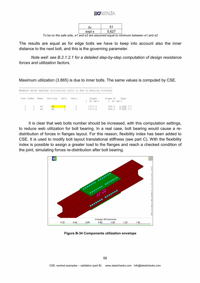
58
CSE: worked examples – validation (part B) www.steelchecks.com [email protected]
p2 51
expl x 5,627 To be on the safe side, e1 and e2 are assumed equal to minimum between e1 and e2
The results are equal as for edge bolts we have to keep into account also the inner
distance to the next bolt, and this is the governing parameter.
Note well: see B.2.1.2.1 for a detailed step-by-step computation of design resistance
forces and utilization factors.
Maximum utilization (3.865) is due to inner bolts. The same values is computed by CSE.
------------------------------------------------------------------
Members whose maximum utilization ratio is due to bearing stresses
------------------------------------------------------------------
Inst Combi Name Boltlay Bolt Extr. Sigma Sigma M Expl
( N/ mm²) ( N/ mm²)
1 1 m1 B5 1 2 1717.4 305.2 5.628 !!!
1 1 m2 B6 1 2 1717.4 305.2 5.628 !!!
It is clear that web bolts number should be increased, with this computation settings,
to reduce web utilization for bolt bearing. In a real case, bolt bearing would cause a re-
distribution of forces in flanges layout. For this reason, flexibility index has been added to
CSE. It is used to modify bolt layout translational stiffness (see part C). With the flexibility
index is possible to assign a greater load to the flanges and reach a checked condition of
the joint, simulating forces re-distribution after bolt bearing.
Figure B-34 Components utilization envelope

59
CSE: worked examples – validation (part B) www.steelchecks.com [email protected]
B.2.1.5 Bending about weak axis
Model used is Validation_SP_1_4.CSE. Plastic moment of the cross-section about
weak axis, including a 1.2 overstrength factor, is.
N08454.2,, efWM RDyzplzpl
Constraints and loads in original imported FEM model were properly set to get that
value in joint node. This is forces distribution computed by CSE.
--------------------------------------------------------------------
Forces acting over bolt layouts at different extremes, global system
--------------------------------------------------------------------
Id Inst Combi Ext Fx Fy Fz Mx My Mz
B3 1 1 1 5.9052e-005 -1.1188e-008 -4.7302e-022 -1.0908e-007 -5.3546e-004 1.2232e+008
B3 1 1 2 -5.9052e-005 1.1188e-008 4.7302e-022 -1.0908e-007 -6.1604e-004 -1.2232e+008
B1 1 1 1 -6.6056e-005 -1.1188e-008 4.6750e-022 -1.0908e-007 5.9421e-004 -1.2232e+008
B1 1 1 2 6.6056e-005 1.1188e-008 -4.6750e-022 -1.0908e-007 6.9389e-004 1.2232e+008
B2 1 1 1 -4.9807e-005 1.1188e-008 4.7297e-022 1.0908e-007 5.3546e-004 -1.2232e+008
B2 1 1 2 4.9807e-005 -1.1188e-008 -4.7297e-022 1.0908e-007 4.3578e-004 1.2232e+008
B4 1 1 1 5.6812e-005 1.1188e-008 -4.6755e-022 1.0908e-007 -5.9421e-004 1.2232e+008
B4 1 1 2 -5.6812e-005 -1.1188e-008 4.6755e-022 1.0908e-007 -5.1362e-004 -1.2232e+008
B5 1 1 1 -2.1088e+004 1.0335e-007 -1.2758e-005 -2.8744e-006 -1.3350e+005 7.6482e-006
B5 1 1 2 6.4560e-008 -3.1504e-017 2.5509e-005 8.1259e-006 7.5203e+005 4.6753e-011
B5 1 1 3 2.1088e+004 -1.0335e-007 -1.2751e-005 -2.8744e-006 -1.3350e+005 -7.6482e-006
B6 1 1 1 2.1088e+004 1.0335e-007 1.2785e-005 -2.8744e-006 1.3350e+005 7.6482e-006
B6 1 1 2 -2.2370e-008 6.8821e-022 -2.5611e-005 8.1259e-006 -7.5203e+005 4.6049e-011
B6 1 1 3 -2.1088e+004 -1.0335e-007 1.2826e-005 -2.8744e-006 1.3350e+005 -7.6482e-006
CSE assings 1.2232e+08Nmm to each flange bolt layout and 7.5203*105Nmm to web bolt
layout. Total moment is equal to applied moment:
2*1.2232*108Nmm + 7.5203*105Nmm = 2.454*108Nmm
Bending in web bolt layouts2 (B5 and B6) produces shears with opposite sign in bolt layout
external extremes.
We are going to compute the force in each bolt of flanges layout. According to what
was previously done for web bolt layout (see Figure B-32), the force in a bolt depends on
total torque, polar inertia moment (Jp) of the layout ad bolt distance from layout centre.
Polar inertia moment was previously computer in paragraph B.1.2; it is
Jp=257211mm2: Force acting on each bolt is equal to:
i
p
t
b dJ
MiT
2/,
2 Note well: we are using “shear only” bolts, so there is no axial force in shafts
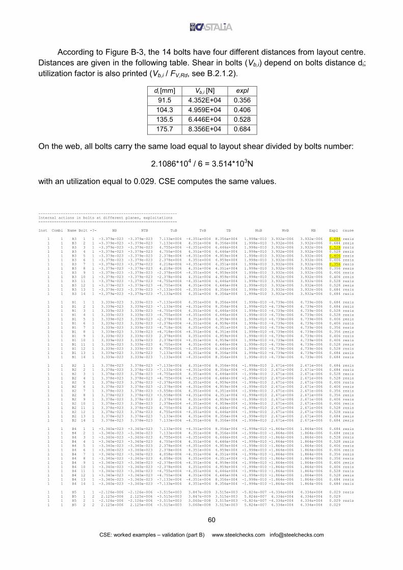
60
CSE: worked examples – validation (part B) www.steelchecks.com [email protected]
According to Figure B-3, the 14 bolts have four different distances from layout centre.
Distances are given in the following table. Shear in bolts (Vb,i) depend on bolts distance di;
utilization factor is also printed (Vb,i / FV,Rd, see B.2.1.2).
di [mm] Vb,i [N] expl
91.5 4.352E+04 0.356
104.3 4.959E+04 0.406
135.5 6.446E+04 0.528
175.7 8.356E+04 0.684
On the web, all bolts carry the same load equal to layout shear divided by bolts number:
2.1086*104 / 6 = 3.514*103N
with an utilization equal to 0.029. CSE computes the same values.
--------------------------------------------------------------
Internal actions in bolts at different planes, exploitations
--------------------------------------------------------------
Inst Combi Name Bolt -?- NB NTB TuB TvB TB MuB MvB MB Expl cause
1 1 B3 1 1 -3.379e-023 -3.379e-023 7.133e+004 -4.351e+004 8.356e+004 1.998e-010 3.932e-006 3.932e-006 0.684 resis
1 1 B3 2 1 -3.379e-023 -3.379e-023 7.133e+004 4.351e+004 8.356e+004 1.998e-010 3.932e-006 3.932e-006 0.684 resis
1 1 B3 3 1 -3.379e-023 -3.379e-023 4.755e+004 -4.351e+004 6.446e+004 1.998e-010 3.932e-006 3.932e-006 0.528 resis
1 1 B3 4 1 -3.379e-023 -3.379e-023 4.755e+004 4.351e+004 6.446e+004 1.998e-010 3.932e-006 3.932e-006 0.528 resis
1 1 B3 5 1 -3.379e-023 -3.379e-023 2.378e+004 -4.351e+004 4.959e+004 1.998e-010 3.932e-006 3.932e-006 0.406 resis
1 1 B3 6 1 -3.379e-023 -3.379e-023 2.378e+004 4.351e+004 4.959e+004 1.998e-010 3.932e-006 3.932e-006 0.406 resis
1 1 B3 7 1 -3.379e-023 -3.379e-023 4.218e-006 -4.351e+004 4.351e+004 1.998e-010 3.932e-006 3.932e-006 0.356 resis
1 1 B3 8 1 -3.379e-023 -3.379e-023 4.218e-006 4.351e+004 4.351e+004 1.998e-010 3.932e-006 3.932e-006 0.356 resis
1 1 B3 9 1 -3.379e-023 -3.379e-023 -2.378e+004 -4.351e+004 4.959e+004 1.998e-010 3.932e-006 3.932e-006 0.406 resis
1 1 B3 10 1 -3.379e-023 -3.379e-023 -2.378e+004 4.351e+004 4.959e+004 1.998e-010 3.932e-006 3.932e-006 0.406 resis
1 1 B3 11 1 -3.379e-023 -3.379e-023 -4.755e+004 -4.351e+004 6.446e+004 1.998e-010 3.932e-006 3.932e-006 0.528 resis
1 1 B3 12 1 -3.379e-023 -3.379e-023 -4.755e+004 4.351e+004 6.446e+004 1.998e-010 3.932e-006 3.932e-006 0.528 resis
1 1 B3 13 1 -3.379e-023 -3.379e-023 -7.133e+004 -4.351e+004 8.356e+004 1.998e-010 3.932e-006 3.932e-006 0.684 resis
1 1 B3 14 1 -3.379e-023 -3.379e-023 -7.133e+004 4.351e+004 8.356e+004 1.998e-010 3.932e-006 3.932e-006 0.684 resis
1 1 B1 1 1 3.339e-023 3.339e-023 -7.133e+004 4.351e+004 8.356e+004 1.998e-010 -4.739e-006 4.739e-006 0.684 resis
1 1 B1 2 1 3.339e-023 3.339e-023 -7.133e+004 -4.351e+004 8.356e+004 1.998e-010 -4.739e-006 4.739e-006 0.684 resis
1 1 B1 3 1 3.339e-023 3.339e-023 -4.755e+004 4.351e+004 6.446e+004 1.998e-010 -4.739e-006 4.739e-006 0.528 resis
1 1 B1 4 1 3.339e-023 3.339e-023 -4.755e+004 -4.351e+004 6.446e+004 1.998e-010 -4.739e-006 4.739e-006 0.528 resis
1 1 B1 5 1 3.339e-023 3.339e-023 -2.378e+004 4.351e+004 4.959e+004 1.998e-010 -4.739e-006 4.739e-006 0.406 resis
1 1 B1 6 1 3.339e-023 3.339e-023 -2.378e+004 -4.351e+004 4.959e+004 1.998e-010 -4.739e-006 4.739e-006 0.406 resis
1 1 B1 7 1 3.339e-023 3.339e-023 -4.718e-006 4.351e+004 4.351e+004 1.998e-010 -4.739e-006 4.739e-006 0.356 resis
1 1 B1 8 1 3.339e-023 3.339e-023 -4.718e-006 -4.351e+004 4.351e+004 1.998e-010 -4.739e-006 4.739e-006 0.356 resis
1 1 B1 9 1 3.339e-023 3.339e-023 2.378e+004 4.351e+004 4.959e+004 1.998e-010 -4.739e-006 4.739e-006 0.406 resis
1 1 B1 10 1 3.339e-023 3.339e-023 2.378e+004 -4.351e+004 4.959e+004 1.998e-010 -4.739e-006 4.739e-006 0.406 resis
1 1 B1 11 1 3.339e-023 3.339e-023 4.755e+004 4.351e+004 6.446e+004 1.998e-010 -4.739e-006 4.739e-006 0.528 resis
1 1 B1 12 1 3.339e-023 3.339e-023 4.755e+004 -4.351e+004 6.446e+004 1.998e-010 -4.739e-006 4.739e-006 0.528 resis
1 1 B1 13 1 3.339e-023 3.339e-023 7.133e+004 4.351e+004 8.356e+004 1.998e-010 -4.739e-006 4.739e-006 0.684 resis
1 1 B1 14 1 3.339e-023 3.339e-023 7.133e+004 -4.351e+004 8.356e+004 1.998e-010 -4.739e-006 4.739e-006 0.684 resis
1 1 B2 1 1 3.378e-023 3.378e-023 -7.133e+004 4.351e+004 8.356e+004 -1.998e-010 2.671e-006 2.671e-006 0.684 resis
1 1 B2 2 1 3.378e-023 3.378e-023 -7.133e+004 -4.351e+004 8.356e+004 -1.998e-010 2.671e-006 2.671e-006 0.684 resis
1 1 B2 3 1 3.378e-023 3.378e-023 -4.755e+004 4.351e+004 6.446e+004 -1.998e-010 2.671e-006 2.671e-006 0.528 resis
1 1 B2 4 1 3.378e-023 3.378e-023 -4.755e+004 -4.351e+004 6.446e+004 -1.998e-010 2.671e-006 2.671e-006 0.528 resis
1 1 B2 5 1 3.378e-023 3.378e-023 -2.378e+004 4.351e+004 4.959e+004 -1.998e-010 2.671e-006 2.671e-006 0.406 resis
1 1 B2 6 1 3.378e-023 3.378e-023 -2.378e+004 -4.351e+004 4.959e+004 -1.998e-010 2.671e-006 2.671e-006 0.406 resis
1 1 B2 7 1 3.378e-023 3.378e-023 -3.558e-006 4.351e+004 4.351e+004 -1.998e-010 2.671e-006 2.671e-006 0.356 resis
1 1 B2 8 1 3.378e-023 3.378e-023 -3.558e-006 -4.351e+004 4.351e+004 -1.998e-010 2.671e-006 2.671e-006 0.356 resis
1 1 B2 9 1 3.378e-023 3.378e-023 2.378e+004 4.351e+004 4.959e+004 -1.998e-010 2.671e-006 2.671e-006 0.406 resis
1 1 B2 10 1 3.378e-023 3.378e-023 2.378e+004 -4.351e+004 4.959e+004 -1.998e-010 2.671e-006 2.671e-006 0.406 resis
1 1 B2 11 1 3.378e-023 3.378e-023 4.755e+004 4.351e+004 6.446e+004 -1.998e-010 2.671e-006 2.671e-006 0.528 resis
1 1 B2 12 1 3.378e-023 3.378e-023 4.755e+004 -4.351e+004 6.446e+004 -1.998e-010 2.671e-006 2.671e-006 0.528 resis
1 1 B2 13 1 3.378e-023 3.378e-023 7.133e+004 4.351e+004 8.356e+004 -1.998e-010 2.671e-006 2.671e-006 0.684 resis
1 1 B2 14 1 3.378e-023 3.378e-023 7.133e+004 -4.351e+004 8.356e+004 -1.998e-010 2.671e-006 2.671e-006 0.684 resis
1 1 B4 1 1 -3.340e-023 -3.340e-023 7.133e+004 -4.351e+004 8.356e+004 -1.998e-010 -1.864e-006 1.864e-006 0.684 resis
1 1 B4 2 1 -3.340e-023 -3.340e-023 7.133e+004 4.351e+004 8.356e+004 -1.998e-010 -1.864e-006 1.864e-006 0.684 resis
1 1 B4 3 1 -3.340e-023 -3.340e-023 4.755e+004 -4.351e+004 6.446e+004 -1.998e-010 -1.864e-006 1.864e-006 0.528 resis
1 1 B4 4 1 -3.340e-023 -3.340e-023 4.755e+004 4.351e+004 6.446e+004 -1.998e-010 -1.864e-006 1.864e-006 0.528 resis
1 1 B4 5 1 -3.340e-023 -3.340e-023 2.378e+004 -4.351e+004 4.959e+004 -1.998e-010 -1.864e-006 1.864e-006 0.406 resis
1 1 B4 6 1 -3.340e-023 -3.340e-023 2.378e+004 4.351e+004 4.959e+004 -1.998e-010 -1.864e-006 1.864e-006 0.406 resis
1 1 B4 7 1 -3.340e-023 -3.340e-023 4.058e-006 -4.351e+004 4.351e+004 -1.998e-010 -1.864e-006 1.864e-006 0.356 resis
1 1 B4 8 1 -3.340e-023 -3.340e-023 4.058e-006 4.351e+004 4.351e+004 -1.998e-010 -1.864e-006 1.864e-006 0.356 resis
1 1 B4 9 1 -3.340e-023 -3.340e-023 -2.378e+004 -4.351e+004 4.959e+004 -1.998e-010 -1.864e-006 1.864e-006 0.406 resis
1 1 B4 10 1 -3.340e-023 -3.340e-023 -2.378e+004 4.351e+004 4.959e+004 -1.998e-010 -1.864e-006 1.864e-006 0.406 resis
1 1 B4 11 1 -3.340e-023 -3.340e-023 -4.755e+004 -4.351e+004 6.446e+004 -1.998e-010 -1.864e-006 1.864e-006 0.528 resis
1 1 B4 12 1 -3.340e-023 -3.340e-023 -4.755e+004 4.351e+004 6.446e+004 -1.998e-010 -1.864e-006 1.864e-006 0.528 resis
1 1 B4 13 1 -3.340e-023 -3.340e-023 -7.133e+004 -4.351e+004 8.356e+004 -1.998e-010 -1.864e-006 1.864e-006 0.684 resis
1 1 B4 14 1 -3.340e-023 -3.340e-023 -7.133e+004 4.351e+004 8.356e+004 -1.998e-010 -1.864e-006 1.864e-006 0.684 resis
1 1 B5 1 1 -2.126e-006 -2.126e-006 -3.515e+003 3.847e-009 3.515e+003 -5.824e-007 -4.334e+004 4.334e+004 0.029 resis
1 1 B5 1 2 2.125e-006 2.125e-006 -3.515e+003 3.847e-009 3.515e+003 5.824e-007 4.334e+004 4.334e+004 0.029
1 1 B5 2 1 -2.126e-006 -2.126e-006 -3.515e+003 3.060e-008 3.515e+003 -5.824e-007 -4.334e+004 4.334e+004 0.029 resis
1 1 B5 2 2 2.125e-006 2.125e-006 -3.515e+003 3.060e-008 3.515e+003 5.824e-007 4.334e+004 4.334e+004 0.029

61
CSE: worked examples – validation (part B) www.steelchecks.com [email protected]
1 1 B5 3 1 -2.126e-006 -2.126e-006 -3.515e+003 3.847e-009 3.515e+003 -5.824e-007 -4.334e+004 4.334e+004 0.029 resis
1 1 B5 3 2 2.125e-006 2.125e-006 -3.515e+003 3.847e-009 3.515e+003 5.824e-007 4.334e+004 4.334e+004 0.029
1 1 B5 4 1 -2.126e-006 -2.126e-006 -3.515e+003 3.060e-008 3.515e+003 -5.824e-007 -4.334e+004 4.334e+004 0.029 resis
1 1 B5 4 2 2.125e-006 2.125e-006 -3.515e+003 3.060e-008 3.515e+003 5.824e-007 4.334e+004 4.334e+004 0.029
1 1 B5 5 1 -2.126e-006 -2.126e-006 -3.515e+003 3.847e-009 3.515e+003 -5.824e-007 -4.334e+004 4.334e+004 0.029 resis
1 1 B5 5 2 2.125e-006 2.125e-006 -3.515e+003 3.847e-009 3.515e+003 5.824e-007 4.334e+004 4.334e+004 0.029
1 1 B5 6 1 -2.126e-006 -2.126e-006 -3.515e+003 3.060e-008 3.515e+003 -5.824e-007 -4.334e+004 4.334e+004 0.029 resis
1 1 B5 6 2 2.125e-006 2.125e-006 -3.515e+003 3.060e-008 3.515e+003 5.824e-007 4.334e+004 4.334e+004 0.029
1 1 B6 1 1 2.131e-006 2.131e-006 3.515e+003 3.847e-009 3.515e+003 -5.824e-007 4.334e+004 4.334e+004 0.029 resis
1 1 B6 1 2 -2.138e-006 -2.138e-006 3.515e+003 3.847e-009 3.515e+003 5.824e-007 -4.334e+004 4.334e+004 0.029
1 1 B6 2 1 2.131e-006 2.131e-006 3.515e+003 3.060e-008 3.515e+003 -5.824e-007 4.334e+004 4.334e+004 0.029 resis
1 1 B6 2 2 -2.138e-006 -2.138e-006 3.515e+003 3.060e-008 3.515e+003 5.824e-007 -4.334e+004 4.334e+004 0.029
1 1 B6 3 1 2.131e-006 2.131e-006 3.515e+003 3.847e-009 3.515e+003 -5.824e-007 4.334e+004 4.334e+004 0.029 resis
1 1 B6 3 2 -2.138e-006 -2.138e-006 3.515e+003 3.847e-009 3.515e+003 5.824e-007 -4.334e+004 4.334e+004 0.029
1 1 B6 4 1 2.131e-006 2.131e-006 3.515e+003 3.060e-008 3.515e+003 -5.824e-007 4.334e+004 4.334e+004 0.029 resis
1 1 B6 4 2 -2.138e-006 -2.138e-006 3.515e+003 3.060e-008 3.515e+003 5.824e-007 -4.334e+004 4.334e+004 0.029
1 1 B6 5 1 2.131e-006 2.131e-006 3.515e+003 3.847e-009 3.515e+003 -5.824e-007 4.334e+004 4.334e+004 0.029 resis
1 1 B6 5 2 -2.138e-006 -2.138e-006 3.515e+003 3.847e-009 3.515e+003 5.824e-007 -4.334e+004 4.334e+004 0.029
1 1 B6 6 1 2.131e-006 2.131e-006 3.515e+003 3.060e-008 3.515e+003 -5.824e-007 4.334e+004 4.334e+004 0.029 resis
1 1 B6 6 2 -2.138e-006 -2.138e-006 3.515e+003 3.060e-008 3.515e+003 5.824e-007 -4.334e+004 4.334e+004 0.029
Now we compute bolt bearing on a flange cover plate. Consider an end/edge bolt and
the most loaded one among inner bolts. Distances are shown in following figure.
Figure B-35
In this case, forces acting on the plate are equal to those in bolts check sections.
--------------------------------------------------------------------
Forces acting over bolt layouts at different extremes, global system
--------------------------------------------------------------------
Id Inst Combi Ext Fx Fy Fz Mx My Mz
B3 1 1 1 5.9052e-005 -1.1188e-008 -4.7302e-022 -1.0908e-007 -5.3546e-004 1.2232e+008

62
CSE: worked examples – validation (part B) www.steelchecks.com [email protected]
------------------------------------------
Overall internal actions over Bolt Layouts
------------------------------------------
Id Inst Combi Sec NT TuT TvT MtT MuT MvT
B3 1 1 1 -4.7302e-022 5.9052e-005 -1.1188e-008 1.2232e+008 2.7969e-009 5.5054e-005
Following table contains all the data needed to compute plate bolt bearing according to the
formulae given in previous paragraphs (see also the appendix). Considered bolt is an
external on (“E” in Figure B-35).
External bolt “E”
Fx 4,351E+04 Fy 7,133E+04
Fb,Rd,x 1,512E+05 Fb,Rd,y 1,555E+05
k1 2,5 k1 1,8
2,8e2/d0-1,7 5,3 2,8e2/d0-1,7 5,3
1,4p2/d0-1,7 11,11 1,4p2/d0-1,7 1,8
2,5
2,5
ab 0,583 ab 0,833
ad 0,833 ad 0,833
fub/fu 2,78 fub/fu 2,78
p1/3d0-0,25 0,58 p1/3d0-0,25 2,80
1
1
fu 360 fu 360
d 18 d 18
d0 20 d0 20
t 20 t 20
e1=min(e1,e2) 50 e1=min(e1,e2) 50
e2=min(e1,e2) 50 e2=min(e1,e2) 50
p1 50 p1 183
p2 183 p2 50
explx 0,288 exply 0,459
EXPL= 0,541
To be on the safe side, e1 and e2 are assumed equal to minimum between e1 and e2
0.541explexplexpl 2
y
2
x
Now we are going to compute bolt bearing due to a inner bolt (most loaded inner bolt, see
“I” in Figure B-35).

63
CSE: worked examples – validation (part B) www.steelchecks.com [email protected]
Inner bolt “I”
Fx 4,351E+04 Fy 4,755E+04
Fb,Rd,x 2,592E+05 Fb,Rd,y 1,512E+05
k1 2,5 k1 2,5
1,4p2/d0-1,7 11,11 2,8e2/d0-1,7 5,3 1,4p2/d0-1,7 11,11
2,5
2,5
ab 1,000 ab 0,583
ad (ext) ad (ext) 0,833
fub/fu 2,78 fub/fu 2,78
p1/3d0-0,25 2,80 p1/3d0-0,25 0,58
1
1
fu 360 fu 360
d 18 d 18
d0 20 d0 20
t 20 t 20
e1=min(e1,e2) 50 e1=min(e1,e2) 50
e2=min(e1,e2) 50 e2=min(e1,e2) 50
p1 183 p1 50
p2 50 p2 183
explx 0,168 exply 0,314
EXPL= 0,356
To be on the safe side, e1 and e2 are assumed equal to minimum between e1 and e2
0.356explexplexpl 2
y
2
x
Note well: see B.2.1.2.1 for a detailed step-by-step computation of design resistance
forces and utilization factors.
Here is the value computed by CSE:
------------------------------------------------------------------
Cleats whose maximum utilization ratio is due to bearing stresses
------------------------------------------------------------------
Inst Combi Name Boltlay Bolt Extr. Sigma Sigma M Expl
( N/ mm²) ( N/ mm²)
1 1 P1 B3 13 1 232.1 428.6 0.541
1 1 P2 B1 14 1 232.1 428.6 0.541

64
CSE: worked examples – validation (part B) www.steelchecks.com [email protected]
Figure B-36 Components utilization envelope
B.2.1.6 Shear parallel to flanges
Now consider the shear parallel to the flanges (model: Validation_SP_1_5.CSE).
With an overstrength factor equal to 1.2, we compute limit shear parallel to flanges
and set imported FEM model to obtain that load in joint node:
Nbtf
VRDfy
RDRDpl
6
, 10856.13
2
Note well: EN1993-1-1 includes a part of flanges area in the shear area for shear
parallel to web. That part should be excluded from shear area for shear parallel to flanges.
Here a simplified computation was done for the load to be applied, considering total
flanges area (2btf).
CSE assigns almost the total load to flanges bolt layouts. A very small part is carried
by web bolt layouts (as bending moment). We will consider flanges bolt, that carry a shear
equal to V=9.2799*105N.
--------------------------------------------------------------------
Forces acting over bolt layouts at different extremes, global system
--------------------------------------------------------------------
Id Inst Combi Ext Fx Fy Fz Mx My Mz
B3 1 1 1 -9.2799e+005 -2.8846e-012 -2.0938e-021 -2.8126e-011 9.0479e+006 1.8560e+008
B3 1 1 2 9.2799e+005 2.8846e-012 2.0938e-021 -2.8123e-011 9.0479e+006 -1.8560e+008

65
CSE: worked examples – validation (part B) www.steelchecks.com [email protected]
B1 1 1 1 9.2799e+005 6.5351e-012 2.0938e-021 6.3716e-011 -9.0479e+006 -1.8560e+008
B1 1 1 2 -9.2799e+005 -6.5351e-012 -2.0938e-021 6.3719e-011 -9.0479e+006 1.8560e+008
B2 1 1 1 9.2799e+005 -6.5351e-012 2.0938e-021 -6.3716e-011 -9.0479e+006 1.8560e+008
B2 1 1 2 -9.2799e+005 6.5351e-012 -2.0938e-021 -6.3718e-011 -9.0479e+006 -1.8560e+008
B4 1 1 1 -9.2799e+005 -6.5351e-012 -2.0938e-021 -6.3716e-011 9.0479e+006 -1.8560e+008
B4 1 1 2 9.2799e+005 6.5351e-012 2.0938e-021 -6.3719e-011 9.0479e+006 1.8560e+008
B5 1 1 1 8.5935e-002 4.6021e-007 -4.4584e+001 -1.2799e-005 3.2998e+003 3.4056e-005
B5 1 1 2 -4.1848e-010 -1.4027e-016 8.9168e+001 3.6183e-005 -6.6015e+003 -4.2191e-013
B5 1 1 3 -8.5935e-002 -4.6021e-007 -4.4584e+001 -1.2799e-005 3.2998e+003 -3.4056e-005
B6 1 1 1 -8.5935e-002 4.6021e-007 -4.4584e+001 -1.2799e-005 3.2987e+003 3.4056e-005
B6 1 1 2 1.4502e-010 -5.7175e-021 8.9169e+001 3.6183e-005 -6.5954e+003 4.1298e-013
B6 1 1 3 8.5935e-002 -4.6021e-007 -4.4584e+001 -1.2799e-005 3.2987e+003 -3.4056e-005
As previously seen for shear parallel to web, we have two components acting on
bolts: the applied shear divided by bolts number and the shear produced by the moment of
transport (torque in the layout).
Figure B-37 Total shear / bolts number (V/14)

66
CSE: worked examples – validation (part B) www.steelchecks.com [email protected]
Figure B-38 Shears due to torque
Figure B-39 Resultant forces
Couples of bolts are subjected to the same force, given by the following formula:
2
,,'
2
,,' )14
( iyMixMi VVV
R
where VM’,x,i and VM’,y,i are the components parallel and normal to the applied shear:
VM’,x,i=M’/Jp*dy,i

67
CSE: worked examples – validation (part B) www.steelchecks.com [email protected]
VM’,y,i=M’/Jp*dx,i
Jp = 257211mm2 is the polar inertia moment, previously computed in B.1.2.
Figure B-40
According to distances shown in previous paragraphs and according to bolts
division in bolts and columns (Figure B-40) we have the same forces acting on bolts
(Newton). Note that VM’,x,i can be oriented like V/14 or opposite to it. Flanges bolt layout are
all in the same condition, of course.
1 2 3 4 5 6 7
Col 1 7.823E+04 6.629E+04 7.261E+04 9.356E+04 1.218E+05 1.534E+05 1.866E+05
Col 2 7.823E+04 6.629E+04 7.261E+04 9.356E+04 1.218E+05 1.534E+05 1.866E+05
Dividing previous table forces by previously computed Fv,Rd=1.221*105N we get the
following utilization factors.
1 2 3 4 5 6 7
Col 1 0.640 0.543 0.594 0.766 0.997 1.256 1.528
Col 2 0.640 0.543 0.594 0.766 0.997 1.256 1.528
Let’s compute step by step the utilization factor of one of the bolts (for example,
column 1 – row 1). Before doing that, we can see that CSE results are equal to previous
computations.
--------------------------------------------------------------
Internal actions in bolts at different planes, exploitations
--------------------------------------------------------------
Inst Combi Name Bolt -?- NB NTB TuB TvB TB MuB MvB MB Expl cause
1 1 B3 1 1 -1.496e-022 -1.496e-022 4.195e+004 -6.602e+004 7.822e+004 5.140e-014 -1.657e+004 1.657e+004 0.640 resis
1 1 B3 2 1 -1.496e-022 -1.496e-022 4.195e+004 6.602e+004 7.822e+004 5.140e-014 -1.657e+004 1.657e+004 0.640 resis
1 1 B3 3 1 -1.496e-022 -1.496e-022 5.873e+003 -6.602e+004 6.628e+004 5.140e-014 -1.657e+004 1.657e+004 0.543 resis

68
CSE: worked examples – validation (part B) www.steelchecks.com [email protected]
1 1 B3 4 1 -1.496e-022 -1.496e-022 5.873e+003 6.602e+004 6.628e+004 5.140e-014 -1.657e+004 1.657e+004 0.543 resis
1 1 B3 5 1 -1.496e-022 -1.496e-022 -3.021e+004 -6.602e+004 7.261e+004 5.140e-014 -1.657e+004 1.657e+004 0.594 resis
1 1 B3 6 1 -1.496e-022 -1.496e-022 -3.021e+004 6.602e+004 7.261e+004 5.140e-014 -1.657e+004 1.657e+004 0.594 resis
1 1 B3 7 1 -1.496e-022 -1.496e-022 -6.628e+004 -6.602e+004 9.356e+004 5.140e-014 -1.657e+004 1.657e+004 0.766 resis
1 1 B3 8 1 -1.496e-022 -1.496e-022 -6.628e+004 6.602e+004 9.356e+004 5.140e-014 -1.657e+004 1.657e+004 0.766 resis
1 1 B3 9 1 -1.496e-022 -1.496e-022 -1.024e+005 -6.602e+004 1.218e+005 5.140e-014 -1.657e+004 1.657e+004 0.997 resis
1 1 B3 10 1 -1.496e-022 -1.496e-022 -1.024e+005 6.602e+004 1.218e+005 5.140e-014 -1.657e+004 1.657e+004 0.997 resis
1 1 B3 11 1 -1.496e-022 -1.496e-022 -1.384e+005 -6.602e+004 1.534e+005 5.140e-014 -1.657e+004 1.657e+004 1.256 resis ***
1 1 B3 12 1 -1.496e-022 -1.496e-022 -1.384e+005 6.602e+004 1.534e+005 5.140e-014 -1.657e+004 1.657e+004 1.256 resis ***
1 1 B3 13 1 -1.496e-022 -1.496e-022 -1.745e+005 -6.602e+004 1.866e+005 5.140e-014 -1.657e+004 1.657e+004 1.528 resis !!!
1 1 B3 14 1 -1.496e-022 -1.496e-022 -1.745e+005 6.602e+004 1.866e+005 5.140e-014 -1.657e+004 1.657e+004 1.528 resis !!!
1 1 B1 1 1 1.496e-022 1.496e-022 -4.195e+004 6.602e+004 7.822e+004 -1.168e-013 1.657e+004 1.657e+004 0.640 resis
1 1 B1 2 1 1.496e-022 1.496e-022 -4.195e+004 -6.602e+004 7.822e+004 -1.168e-013 1.657e+004 1.657e+004 0.640 resis
1 1 B1 3 1 1.496e-022 1.496e-022 -5.873e+003 6.602e+004 6.628e+004 -1.168e-013 1.657e+004 1.657e+004 0.543 resis
1 1 B1 4 1 1.496e-022 1.496e-022 -5.873e+003 -6.602e+004 6.628e+004 -1.168e-013 1.657e+004 1.657e+004 0.543 resis
1 1 B1 5 1 1.496e-022 1.496e-022 3.021e+004 6.602e+004 7.261e+004 -1.168e-013 1.657e+004 1.657e+004 0.594 resis
1 1 B1 6 1 1.496e-022 1.496e-022 3.021e+004 -6.602e+004 7.261e+004 -1.168e-013 1.657e+004 1.657e+004 0.594 resis
1 1 B1 7 1 1.496e-022 1.496e-022 6.628e+004 6.602e+004 9.356e+004 -1.168e-013 1.657e+004 1.657e+004 0.766 resis
1 1 B1 8 1 1.496e-022 1.496e-022 6.628e+004 -6.602e+004 9.356e+004 -1.168e-013 1.657e+004 1.657e+004 0.766 resis
1 1 B1 9 1 1.496e-022 1.496e-022 1.024e+005 6.602e+004 1.218e+005 -1.168e-013 1.657e+004 1.657e+004 0.997 resis
1 1 B1 10 1 1.496e-022 1.496e-022 1.024e+005 -6.602e+004 1.218e+005 -1.168e-013 1.657e+004 1.657e+004 0.997 resis
1 1 B1 11 1 1.496e-022 1.496e-022 1.384e+005 6.602e+004 1.534e+005 -1.168e-013 1.657e+004 1.657e+004 1.256 resis ***
1 1 B1 12 1 1.496e-022 1.496e-022 1.384e+005 -6.602e+004 1.534e+005 -1.168e-013 1.657e+004 1.657e+004 1.256 resis ***
1 1 B1 13 1 1.496e-022 1.496e-022 1.745e+005 6.602e+004 1.866e+005 -1.168e-013 1.657e+004 1.657e+004 1.528 resis !!!
1 1 B1 14 1 1.496e-022 1.496e-022 1.745e+005 -6.602e+004 1.866e+005 -1.168e-013 1.657e+004 1.657e+004 1.528 resis !!!
1 1 B2 1 1 1.496e-022 1.496e-022 1.745e+005 -6.602e+004 1.866e+005 1.168e-013 1.657e+004 1.657e+004 1.528 resis !!!
1 1 B2 2 1 1.496e-022 1.496e-022 1.745e+005 6.602e+004 1.866e+005 1.168e-013 1.657e+004 1.657e+004 1.528 resis !!!
1 1 B2 3 1 1.496e-022 1.496e-022 1.384e+005 -6.602e+004 1.534e+005 1.168e-013 1.657e+004 1.657e+004 1.256 resis ***
1 1 B2 4 1 1.496e-022 1.496e-022 1.384e+005 6.602e+004 1.534e+005 1.168e-013 1.657e+004 1.657e+004 1.256 resis ***
1 1 B2 5 1 1.496e-022 1.496e-022 1.024e+005 -6.602e+004 1.218e+005 1.168e-013 1.657e+004 1.657e+004 0.997 resis
1 1 B2 6 1 1.496e-022 1.496e-022 1.024e+005 6.602e+004 1.218e+005 1.168e-013 1.657e+004 1.657e+004 0.997 resis
1 1 B2 7 1 1.496e-022 1.496e-022 6.628e+004 -6.602e+004 9.356e+004 1.168e-013 1.657e+004 1.657e+004 0.766 resis
1 1 B2 8 1 1.496e-022 1.496e-022 6.628e+004 6.602e+004 9.356e+004 1.168e-013 1.657e+004 1.657e+004 0.766 resis
1 1 B2 9 1 1.496e-022 1.496e-022 3.021e+004 -6.602e+004 7.261e+004 1.168e-013 1.657e+004 1.657e+004 0.594 resis
1 1 B2 10 1 1.496e-022 1.496e-022 3.021e+004 6.602e+004 7.261e+004 1.168e-013 1.657e+004 1.657e+004 0.594 resis
1 1 B2 11 1 1.496e-022 1.496e-022 -5.873e+003 -6.602e+004 6.629e+004 1.168e-013 1.657e+004 1.657e+004 0.543 resis
1 1 B2 12 1 1.496e-022 1.496e-022 -5.873e+003 6.602e+004 6.629e+004 1.168e-013 1.657e+004 1.657e+004 0.543 resis
1 1 B2 13 1 1.496e-022 1.496e-022 -4.195e+004 -6.602e+004 7.823e+004 1.168e-013 1.657e+004 1.657e+004 0.640 resis
1 1 B2 14 1 1.496e-022 1.496e-022 -4.195e+004 6.602e+004 7.823e+004 1.168e-013 1.657e+004 1.657e+004 0.640 resis
1 1 B4 1 1 -1.496e-022 -1.496e-022 -1.745e+005 6.602e+004 1.866e+005 1.168e-013 -1.657e+004 1.657e+004 1.528 resis !!!
1 1 B4 2 1 -1.496e-022 -1.496e-022 -1.745e+005 -6.602e+004 1.866e+005 1.168e-013 -1.657e+004 1.657e+004 1.528 resis !!!
1 1 B4 3 1 -1.496e-022 -1.496e-022 -1.384e+005 6.602e+004 1.534e+005 1.168e-013 -1.657e+004 1.657e+004 1.256 resis ***
1 1 B4 4 1 -1.496e-022 -1.496e-022 -1.384e+005 -6.602e+004 1.534e+005 1.168e-013 -1.657e+004 1.657e+004 1.256 resis ***
1 1 B4 5 1 -1.496e-022 -1.496e-022 -1.024e+005 6.602e+004 1.218e+005 1.168e-013 -1.657e+004 1.657e+004 0.997 resis
1 1 B4 6 1 -1.496e-022 -1.496e-022 -1.024e+005 -6.602e+004 1.218e+005 1.168e-013 -1.657e+004 1.657e+004 0.997 resis
1 1 B4 7 1 -1.496e-022 -1.496e-022 -6.628e+004 6.602e+004 9.356e+004 1.168e-013 -1.657e+004 1.657e+004 0.766 resis
1 1 B4 8 1 -1.496e-022 -1.496e-022 -6.628e+004 -6.602e+004 9.356e+004 1.168e-013 -1.657e+004 1.657e+004 0.766 resis
1 1 B4 9 1 -1.496e-022 -1.496e-022 -3.021e+004 6.602e+004 7.261e+004 1.168e-013 -1.657e+004 1.657e+004 0.594 resis
1 1 B4 10 1 -1.496e-022 -1.496e-022 -3.021e+004 -6.602e+004 7.261e+004 1.168e-013 -1.657e+004 1.657e+004 0.594 resis
1 1 B4 11 1 -1.496e-022 -1.496e-022 5.873e+003 6.602e+004 6.629e+004 1.168e-013 -1.657e+004 1.657e+004 0.543 resis
1 1 B4 12 1 -1.496e-022 -1.496e-022 5.873e+003 -6.602e+004 6.629e+004 1.168e-013 -1.657e+004 1.657e+004 0.543 resis
1 1 B4 13 1 -1.496e-022 -1.496e-022 4.195e+004 6.602e+004 7.823e+004 1.168e-013 -1.657e+004 1.657e+004 0.640 resis
1 1 B4 14 1 -1.496e-022 -1.496e-022 4.195e+004 -6.602e+004 7.823e+004 1.168e-013 -1.657e+004 1.657e+004 0.640 resis
1 1 B5 1 1 -7.431e+000 -7.431e+000 1.432e-002 1.713e-008 1.432e-002 -2.593e-006 5.500e+002 5.500e+002 0.000
1 1 B5 1 2 7.431e+000 7.431e+000 1.432e-002 1.713e-008 1.432e-002 2.593e-006 -5.500e+002 5.500e+002 0.000 resis
1 1 B5 2 1 -7.431e+000 -7.431e+000 1.432e-002 1.363e-007 1.432e-002 -2.593e-006 5.500e+002 5.500e+002 0.000
1 1 B5 2 2 7.431e+000 7.431e+000 1.432e-002 1.363e-007 1.432e-002 2.593e-006 -5.500e+002 5.500e+002 0.000 resis
1 1 B5 3 1 -7.431e+000 -7.431e+000 1.432e-002 1.713e-008 1.432e-002 -2.593e-006 5.500e+002 5.500e+002 0.000
1 1 B5 3 2 7.431e+000 7.431e+000 1.432e-002 1.713e-008 1.432e-002 2.593e-006 -5.500e+002 5.500e+002 0.000 resis
1 1 B5 4 1 -7.431e+000 -7.431e+000 1.432e-002 1.363e-007 1.432e-002 -2.593e-006 5.500e+002 5.500e+002 0.000
1 1 B5 4 2 7.431e+000 7.431e+000 1.432e-002 1.363e-007 1.432e-002 2.593e-006 -5.500e+002 5.500e+002 0.000 resis
1 1 B5 5 1 -7.431e+000 -7.431e+000 1.432e-002 1.713e-008 1.432e-002 -2.593e-006 5.500e+002 5.500e+002 0.000
1 1 B5 5 2 7.431e+000 7.431e+000 1.432e-002 1.713e-008 1.432e-002 2.593e-006 -5.500e+002 5.500e+002 0.000 resis
1 1 B5 6 1 -7.431e+000 -7.431e+000 1.432e-002 1.363e-007 1.432e-002 -2.593e-006 5.500e+002 5.500e+002 0.000
1 1 B5 6 2 7.431e+000 7.431e+000 1.432e-002 1.363e-007 1.432e-002 2.593e-006 -5.500e+002 5.500e+002 0.000 resis
1 1 B6 1 1 -7.431e+000 -7.431e+000 -1.432e-002 1.713e-008 1.432e-002 -2.593e-006 5.497e+002 5.497e+002 0.000
1 1 B6 1 2 7.431e+000 7.431e+000 -1.432e-002 1.713e-008 1.432e-002 2.593e-006 -5.497e+002 5.497e+002 0.000 resis
1 1 B6 2 1 -7.431e+000 -7.431e+000 -1.432e-002 1.363e-007 1.432e-002 -2.593e-006 5.497e+002 5.497e+002 0.000
1 1 B6 2 2 7.431e+000 7.431e+000 -1.432e-002 1.363e-007 1.432e-002 2.593e-006 -5.497e+002 5.497e+002 0.000 resis
1 1 B6 3 1 -7.431e+000 -7.431e+000 -1.432e-002 1.713e-008 1.432e-002 -2.593e-006 5.497e+002 5.497e+002 0.000
1 1 B6 3 2 7.431e+000 7.431e+000 -1.432e-002 1.713e-008 1.432e-002 2.593e-006 -5.497e+002 5.497e+002 0.000 resis
1 1 B6 4 1 -7.431e+000 -7.431e+000 -1.432e-002 1.363e-007 1.432e-002 -2.593e-006 5.497e+002 5.497e+002 0.000
1 1 B6 4 2 7.431e+000 7.431e+000 -1.432e-002 1.363e-007 1.432e-002 2.593e-006 -5.497e+002 5.497e+002 0.000 resis
1 1 B6 5 1 -7.431e+000 -7.431e+000 -1.432e-002 1.713e-008 1.432e-002 -2.593e-006 5.497e+002 5.497e+002 0.000
1 1 B6 5 2 7.431e+000 7.431e+000 -1.432e-002 1.713e-008 1.432e-002 2.593e-006 -5.497e+002 5.497e+002 0.000 resis
1 1 B6 6 1 -7.431e+000 -7.431e+000 -1.432e-002 1.363e-007 1.432e-002 -2.593e-006 5.497e+002 5.497e+002 0.000
1 1 B6 6 2 7.431e+000 7.431e+000 -1.432e-002 1.363e-007 1.432e-002 2.593e-006 -5.497e+002 5.497e+002 0.000 resis
Now we compute the utilization for bolt in column 1 – row 1 (Figure B-40). The
formula is the following, already used in previous paragraphs.
2
,,'
2
,,'14
iyMixMi VVV
R
with
V/14 = 9.280*105N / 14= 6.629*104N

69
CSE: worked examples – validation (part B) www.steelchecks.com [email protected]
VM’,x,i = M’/ Jp * dy,i = 1.856*108Nmm / 257211 * 150mm = 1.082*105N
VM’,y,i = M’/ Jp * dx,i = 1.856*108Nmm / 257211 * 91.5mm = 6.603*104N
where M’ is the moment of transport due to the shear. According to the distance
shown in the following figure, we have:
M’ = T * d = 9.280*105N * 200mm = 1.856*108Nmm.
Figure B-41 Distance between bolt layout centre and shear application point
On considered bolt, parallel shear components have opposite (see Figure B-39); we have:
NNNNVVV
R iyMixMi
4242542
,,'
2
,,' 10823.710603.610082.110629.614
It is the force given for column 1 – row 1 in previous table.
Now we are going to compute bolt bearing on a flange cover plate. As previously done in
last paragraph, we will consider the most loaded among end/edge bolts (col 1 row 7,
referring to Figure B-40) and the most loaded among inner bolts (row 1, column 6).
Bolt: col 1 – row 7
Fx 1,745E+05 Fy 6,602E+04
Fb,Rd,x 1,555E+05 Fb,Rd,y 1,512E+05
k1 1,8 k1 2,5
2,8e2/d0-1,7 5,3 2,8e2/d0-1,7 5,3
1,4p2/d0-1,7 1,8 1,4p2/d0-1,7 11,11

70
CSE: worked examples – validation (part B) www.steelchecks.com [email protected]
2,5
2,5
ab 0,833 ab 0,583
ad 0,833 ad 0,833
fub/fu 2,78 fub/fu 2,78
p1/3d0-0,25 2,80 p1/3d0-0,25 0,58
1
1
fu 360 fu 360
d 18 d 18
d0 20 d0 20
t 20 t 20
e1=min(e1,e2) 50 e1=min(e1,e2) 50
e2=min(e1,e2) 50 e2=min(e1,e2) 50
p1 183 p1 50
p2 50 p2 183
explx 1,122 exply 0,437
EXPL= 1,204
To be on the safe side, e1 and e2 are assumed equal to minimum between e1 and e2
.2041explexplexpl 2
y
2
x
Bolt: col 1 – row 6
Fx 1,384E+05 Fy 6,602E+04
Fb,Rd,x 2,160E+05 Fb,Rd,y 1,512E+05
k1 2,5 k1 2,5
1,4p2/d0-1,7 11,11 2,8e2/d0-1,7 5,3
1,4p2/d0-1,7 11,11
2,5
2,5
ab 0,833 ab 0,583
ad (end) 0,833 ad (inner) 2,800
fub/fu 2,78 fub/fu 2,78
p1/3d0-0,25 2,80 p1/3d0-0,25 0,58
1
1
fu 360 fu 360
d 18 d 18
d0 20 d0 20
t 20 t 20
e1=min(e1,e2) 50 e1=min(e1,e2) 50
e2=min(e1,e2) 50 e2=min(e1,e2) 50
p1 183 p1 50
p2 50 p2 183
explx 0,641 exply 0,437

71
CSE: worked examples – validation (part B) www.steelchecks.com [email protected]
EXPL= 0,776
To be on the safe side, e1 and e2 are assumed equal to minimum between e1 and e2
0.992explexplexpl 2
y
2
x
Note well: see B.2.1.2.1 for a detailed step-by-step computation of design resistance
forces and utilization factors.
Inner bolt gives maximum utilization for plate bolt bearing check. CSE computes the
same value.
------------------------------------------------------------------
Cleats whose maximum utilization ratio is due to bearing stresses
------------------------------------------------------------------
Inst Combi Name Boltlay Bolt Extr. Sigma Sigma M Expl
( N/ mm²) ( N/ mm²)
1 1 P1 B2 1 1 518.3 430.4 1.204 ***
1 1 P2 B4 1 1 518.3 430.4 1.204 ***
1 1 P3 B6 6 1 0.0 305.2 0.000
1 1 P4 B6 6 3 0.0 305.2 0.000
For example, considering plate P2, maximum utilization is due to bolt #1 of bolt layout
B4, corresponding to column 1-row 7 (see next figure).
Figure B-42 Bolt layout B4 – Bolt #3 highlighted
Web plates utilization is null, since web bolt layouts do not carry loads (see P3 and
P4 in previous output listing abstract).

72
CSE: worked examples – validation (part B) www.steelchecks.com [email protected]
Figure B-43 Exploitation envelope according to EN 1993-1-8: 2005
B.2.1.7 Torque
Model name: Validation_SP_1_6.CSE. Constraints and loads on imported FEM
model are set to get, in joint node, only a torque equal to member elastic limit. Its value is
computed through the following formula.
Nmmt
fJM
yt
t
7
max
10321.13
It is not easy to compute forces distribution by hand. If the whole loads would be
carried by flanges bolt layouts, we would have the following shear force on each flange bolt
layout:
V=Mt/h=4.405*104N

73
CSE: worked examples – validation (part B) www.steelchecks.com [email protected]
Figure B-44
We expect that also web bolt layouts carry a small part of the load. Let’s see how
CSE computes forces distribution.
--------------------------------------------------------------------
Forces acting over bolt layouts at different extremes, global system
--------------------------------------------------------------------
Id Inst Combi Ext Fx Fy Fz Mx My Mz
B3 1 1 1 4.3239e+004 8.5056e-008 5.9098e-012 7.7949e-007 -3.6190e+005 -8.9393e+006
B3 1 1 2 -4.3239e+004 -8.5056e-008 -5.9098e-012 8.7911e-007 -4.8126e+005 8.9393e+006
B1 1 1 1 4.3239e+004 -8.5038e-008 -5.8796e-012 -7.7928e-007 -3.6190e+005 -8.5508e+006
B1 1 1 2 -4.3239e+004 8.5038e-008 5.8796e-012 -8.7897e-007 -4.8126e+005 8.5508e+006
B2 1 1 1 -4.3239e+004 -8.5056e-008 -5.9098e-012 -7.7706e-007 3.6190e+005 -8.7454e+006
B2 1 1 2 4.3239e+004 8.5056e-008 5.9098e-012 -8.8152e-007 4.8126e+005 8.7454e+006
B4 1 1 1 -4.3239e+004 8.5038e-008 5.8796e-012 7.7693e-007 3.6190e+005 -8.7448e+006
B4 1 1 2 4.3239e+004 -8.5038e-008 -5.8796e-012 8.8132e-007 4.8126e+005 8.7448e+006
B5 1 1 1 1.6721e+001 -1.2923e+003 2.6607e-002 3.5941e+004 1.0389e+002 -9.5632e+004
B5 1 1 2 -5.1017e-011 3.9390e-007 -5.3214e-002 -1.0161e+005 -5.9237e+002 3.2232e-005
B5 1 1 3 -1.6721e+001 1.2923e+003 2.6607e-002 3.5941e+004 1.0389e+002 9.5632e+004
B6 1 1 1 -1.6721e+001 -1.2923e+003 2.6607e-002 3.5941e+004 -1.0782e+002 -9.5632e+004
B6 1 1 2 1.7600e-011 1.3188e-011 -5.3215e-002 -1.0161e+005 6.0024e+002 -2.5657e-005
B6 1 1 3 1.6721e+001 1.2923e+003 2.6607e-002 3.5941e+004 -1.0782e+002 9.5632e+004
CSE assigns Vf = 4.324*104N to each flange bolt layout: it is the 98.2% of shear they
would carry neglecting web bolt layout contribution. Note well: we are using “shear only”
bolts, as previously explained.
To compute shear force in each bolt, we use the same scheme used in paragraph
B.2.1.6), using current values of V and M’ computed by CSE; forces are in Newton, bolts
numbering is the same of Figure B-40.
1 2 3 4 5 6 7
Col1 3.825E+03 3.204E+03 3.455E+03 4.433E+03 5.780E+03 7.294E+03 8.890E+03
Col 2 3.825E+03 3.204E+03 3.455E+03 4.433E+03 5.780E+03 7.294E+03 8.890E+03

74
CSE: worked examples – validation (part B) www.steelchecks.com [email protected]
Dividing previous forces by bolt design resistance to shear (Fv,Rd=1.221*105N, see
previous paragraphs) we get the following utilization factors.
1 2 3 4 5 6 7
Col 1 0.031 0.026 0.028 0.036 0.047 0.060 0.073
Col 2 0.031 0.026 0.028 0.036 0.047 0.060 0.073
Let’s compute in detail one of the bolts, for example the one in row 1, column 1.
2
,,'
2
,,'14
iyMixM
f
i VVV
R
with
Vf/14 = 4.324x10⁴N / 14= 3.089*103N
VM’,x,i = M’/ Jp * dy,i = 8.9393 * 106Nmm / 257211 * 150mm = 5.213*103N
VM’,y,i = M’/ Jp * dx,i = 8.9393 * 106Nmm / 257211 * 91.5mm = 3.180*103N
Where M’ is the moment of transport due to the shear. With a simplified V*d
computation it would be:
M’ = V * d = 4.324 * 104N * 200mm = 8.650*106Nmm
CSE considers also the bending in bolts shafts, at each bolting level, computing a
more accurate moment of transport. Computed moment value is 8.9393*106Nmm (see
previous output listing abstract). Let’s continue with accurate computation done by CSE.
On considered bolt, forces components have opposite sign (see Figure B-39); we have:
NNNNVVV
R iyMixM
f
i
3232332
,,'
2
,,' 10825.310180.310213.510089.314
According to previous table, CSE computes the same forces and exploitation values.
--------------------------------------------------------------
Internal actions in bolts at different planes, exploitations
--------------------------------------------------------------
Inst Combi Name Bolt -?- NB NTB TuB TvB TB MuB MvB MB Expl cause
1 1 B3 1 1 4.221e-013 4.221e-013 -2.125e+003 3.180e+003 3.825e+003 -5.077e-009 5.035e+003 5.035e+003 0.031 resis
1 1 B3 2 1 4.221e-013 4.221e-013 -2.125e+003 -3.180e+003 3.825e+003 -5.077e-009 5.035e+003 5.035e+003 0.031 resis
1 1 B3 3 1 4.221e-013 4.221e-013 -3.870e+002 3.180e+003 3.204e+003 -5.077e-009 5.035e+003 5.035e+003 0.026 resis
1 1 B3 4 1 4.221e-013 4.221e-013 -3.870e+002 -3.180e+003 3.204e+003 -5.077e-009 5.035e+003 5.035e+003 0.026 resis
1 1 B3 5 1 4.221e-013 4.221e-013 1.351e+003 3.180e+003 3.455e+003 -5.077e-009 5.035e+003 5.035e+003 0.028 resis

75
CSE: worked examples – validation (part B) www.steelchecks.com [email protected]
1 1 B3 6 1 4.221e-013 4.221e-013 1.351e+003 -3.180e+003 3.455e+003 -5.077e-009 5.035e+003 5.035e+003 0.028 resis
1 1 B3 7 1 4.221e-013 4.221e-013 3.088e+003 3.180e+003 4.433e+003 -5.077e-009 5.035e+003 5.035e+003 0.036 resis
1 1 B3 8 1 4.221e-013 4.221e-013 3.088e+003 -3.180e+003 4.433e+003 -5.077e-009 5.035e+003 5.035e+003 0.036 resis
1 1 B3 9 1 4.221e-013 4.221e-013 4.826e+003 3.180e+003 5.780e+003 -5.077e-009 5.035e+003 5.035e+003 0.047 resis
1 1 B3 10 1 4.221e-013 4.221e-013 4.826e+003 -3.180e+003 5.780e+003 -5.077e-009 5.035e+003 5.035e+003 0.047 resis
1 1 B3 11 1 4.221e-013 4.221e-013 6.564e+003 3.180e+003 7.294e+003 -5.077e-009 5.035e+003 5.035e+003 0.060 resis
1 1 B3 12 1 4.221e-013 4.221e-013 6.564e+003 -3.180e+003 7.294e+003 -5.077e-009 5.035e+003 5.035e+003 0.060 resis
1 1 B3 13 1 4.221e-013 4.221e-013 8.302e+003 3.180e+003 8.890e+003 -5.077e-009 5.035e+003 5.035e+003 0.073 resis
1 1 B3 14 1 4.221e-013 4.221e-013 8.302e+003 -3.180e+003 8.890e+003 -5.077e-009 5.035e+003 5.035e+003 0.073 resis
1 1 B1 1 1 -4.200e-013 -4.200e-013 -1.898e+003 3.042e+003 3.585e+003 5.079e-009 5.035e+003 5.035e+003 0.029 resis
1 1 B1 2 1 -4.200e-013 -4.200e-013 -1.898e+003 -3.042e+003 3.585e+003 5.079e-009 5.035e+003 5.035e+003 0.029 resis
1 1 B1 3 1 -4.200e-013 -4.200e-013 -2.359e+002 3.042e+003 3.051e+003 5.079e-009 5.035e+003 5.035e+003 0.025 resis
1 1 B1 4 1 -4.200e-013 -4.200e-013 -2.359e+002 -3.042e+003 3.051e+003 5.079e-009 5.035e+003 5.035e+003 0.025 resis
1 1 B1 5 1 -4.200e-013 -4.200e-013 1.426e+003 3.042e+003 3.360e+003 5.079e-009 5.035e+003 5.035e+003 0.028 resis
1 1 B1 6 1 -4.200e-013 -4.200e-013 1.426e+003 -3.042e+003 3.360e+003 5.079e-009 5.035e+003 5.035e+003 0.028 resis
1 1 B1 7 1 -4.200e-013 -4.200e-013 3.088e+003 3.042e+003 4.335e+003 5.079e-009 5.035e+003 5.035e+003 0.035 resis
1 1 B1 8 1 -4.200e-013 -4.200e-013 3.088e+003 -3.042e+003 4.335e+003 5.079e-009 5.035e+003 5.035e+003 0.035 resis
1 1 B1 9 1 -4.200e-013 -4.200e-013 4.751e+003 3.042e+003 5.641e+003 5.079e-009 5.035e+003 5.035e+003 0.046 resis
1 1 B1 10 1 -4.200e-013 -4.200e-013 4.751e+003 -3.042e+003 5.641e+003 5.079e-009 5.035e+003 5.035e+003 0.046 resis
1 1 B1 11 1 -4.200e-013 -4.200e-013 6.413e+003 3.042e+003 7.098e+003 5.079e-009 5.035e+003 5.035e+003 0.058 resis
1 1 B1 12 1 -4.200e-013 -4.200e-013 6.413e+003 -3.042e+003 7.098e+003 5.079e-009 5.035e+003 5.035e+003 0.058 resis
1 1 B1 13 1 -4.200e-013 -4.200e-013 8.075e+003 3.042e+003 8.629e+003 5.079e-009 5.035e+003 5.035e+003 0.071 resis
1 1 B1 14 1 -4.200e-013 -4.200e-013 8.075e+003 -3.042e+003 8.629e+003 5.079e-009 5.035e+003 5.035e+003 0.071 resis
1 1 B2 1 1 -4.221e-013 -4.221e-013 -8.189e+003 3.111e+003 8.760e+003 5.250e-009 -5.035e+003 5.035e+003 0.072 resis
1 1 B2 2 1 -4.221e-013 -4.221e-013 -8.189e+003 -3.111e+003 8.760e+003 5.250e-009 -5.035e+003 5.035e+003 0.072 resis
1 1 B2 3 1 -4.221e-013 -4.221e-013 -6.489e+003 3.111e+003 7.196e+003 5.250e-009 -5.035e+003 5.035e+003 0.059 resis
1 1 B2 4 1 -4.221e-013 -4.221e-013 -6.489e+003 -3.111e+003 7.196e+003 5.250e-009 -5.035e+003 5.035e+003 0.059 resis
1 1 B2 5 1 -4.221e-013 -4.221e-013 -4.789e+003 3.111e+003 5.710e+003 5.250e-009 -5.035e+003 5.035e+003 0.047 resis
1 1 B2 6 1 -4.221e-013 -4.221e-013 -4.789e+003 -3.111e+003 5.710e+003 5.250e-009 -5.035e+003 5.035e+003 0.047 resis
1 1 B2 7 1 -4.221e-013 -4.221e-013 -3.088e+003 3.111e+003 4.384e+003 5.250e-009 -5.035e+003 5.035e+003 0.036 resis
1 1 B2 8 1 -4.221e-013 -4.221e-013 -3.088e+003 -3.111e+003 4.384e+003 5.250e-009 -5.035e+003 5.035e+003 0.036 resis
1 1 B2 9 1 -4.221e-013 -4.221e-013 -1.388e+003 3.111e+003 3.407e+003 5.250e-009 -5.035e+003 5.035e+003 0.028 resis
1 1 B2 10 1 -4.221e-013 -4.221e-013 -1.388e+003 -3.111e+003 3.407e+003 5.250e-009 -5.035e+003 5.035e+003 0.028 resis
1 1 B2 11 1 -4.221e-013 -4.221e-013 3.116e+002 3.111e+003 3.127e+003 5.250e-009 -5.035e+003 5.035e+003 0.026 resis
1 1 B2 12 1 -4.221e-013 -4.221e-013 3.116e+002 -3.111e+003 3.127e+003 5.250e-009 -5.035e+003 5.035e+003 0.026 resis
1 1 B2 13 1 -4.221e-013 -4.221e-013 2.012e+003 3.111e+003 3.705e+003 5.250e-009 -5.035e+003 5.035e+003 0.030 resis
1 1 B2 14 1 -4.221e-013 -4.221e-013 2.012e+003 -3.111e+003 3.705e+003 5.250e-009 -5.035e+003 5.035e+003 0.030 resis
1 1 B4 1 1 4.200e-013 4.200e-013 -8.188e+003 3.111e+003 8.759e+003 -5.247e-009 -5.035e+003 5.035e+003 0.072 resis
1 1 B4 2 1 4.200e-013 4.200e-013 -8.188e+003 -3.111e+003 8.759e+003 -5.247e-009 -5.035e+003 5.035e+003 0.072 resis
1 1 B4 3 1 4.200e-013 4.200e-013 -6.488e+003 3.111e+003 7.196e+003 -5.247e-009 -5.035e+003 5.035e+003 0.059 resis
1 1 B4 4 1 4.200e-013 4.200e-013 -6.488e+003 -3.111e+003 7.196e+003 -5.247e-009 -5.035e+003 5.035e+003 0.059 resis
1 1 B4 5 1 4.200e-013 4.200e-013 -4.788e+003 3.111e+003 5.710e+003 -5.247e-009 -5.035e+003 5.035e+003 0.047 resis
1 1 B4 6 1 4.200e-013 4.200e-013 -4.788e+003 -3.111e+003 5.710e+003 -5.247e-009 -5.035e+003 5.035e+003 0.047 resis
1 1 B4 7 1 4.200e-013 4.200e-013 -3.088e+003 3.111e+003 4.384e+003 -5.247e-009 -5.035e+003 5.035e+003 0.036 resis
1 1 B4 8 1 4.200e-013 4.200e-013 -3.088e+003 -3.111e+003 4.384e+003 -5.247e-009 -5.035e+003 5.035e+003 0.036 resis
1 1 B4 9 1 4.200e-013 4.200e-013 -1.389e+003 3.111e+003 3.407e+003 -5.247e-009 -5.035e+003 5.035e+003 0.028 resis
1 1 B4 10 1 4.200e-013 4.200e-013 -1.389e+003 -3.111e+003 3.407e+003 -5.247e-009 -5.035e+003 5.035e+003 0.028 resis
1 1 B4 11 1 4.200e-013 4.200e-013 3.113e+002 3.111e+003 3.126e+003 -5.247e-009 -5.035e+003 5.035e+003 0.026 resis
1 1 B4 12 1 4.200e-013 4.200e-013 3.113e+002 -3.111e+003 3.126e+003 -5.247e-009 -5.035e+003 5.035e+003 0.026 resis
1 1 B4 13 1 4.200e-013 4.200e-013 2.011e+003 3.111e+003 3.704e+003 -5.247e-009 -5.035e+003 5.035e+003 0.030 resis
1 1 B4 14 1 4.200e-013 4.200e-013 2.011e+003 -3.111e+003 3.704e+003 -5.247e-009 -5.035e+003 5.035e+003 0.030 resis
1 1 B5 1 1 4.435e-003 4.435e-003 -3.454e+002 -4.810e+001 3.488e+002 7.282e+003 3.404e+001 7.283e+003 0.003 resis
1 1 B5 1 2 -4.435e-003 -4.435e-003 -3.454e+002 -4.810e+001 3.488e+002 -7.282e+003 -3.404e+001 7.283e+003 0.003
1 1 B5 2 1 4.435e-003 4.435e-003 -3.454e+002 -3.827e+002 5.155e+002 7.282e+003 3.404e+001 7.283e+003 0.004 resis
1 1 B5 2 2 -4.435e-003 -4.435e-003 -3.454e+002 -3.827e+002 5.155e+002 -7.282e+003 -3.404e+001 7.283e+003 0.004
1 1 B5 3 1 4.435e-003 4.435e-003 2.787e+000 -4.810e+001 4.818e+001 7.282e+003 3.404e+001 7.283e+003 0.000 resis
1 1 B5 3 2 -4.435e-003 -4.435e-003 2.787e+000 -4.810e+001 4.818e+001 -7.282e+003 -3.404e+001 7.283e+003 0.000
1 1 B5 4 1 4.435e-003 4.435e-003 2.787e+000 -3.827e+002 3.827e+002 7.282e+003 3.404e+001 7.283e+003 0.003 resis
1 1 B5 4 2 -4.435e-003 -4.435e-003 2.787e+000 -3.827e+002 3.827e+002 -7.282e+003 -3.404e+001 7.283e+003 0.003
1 1 B5 5 1 4.435e-003 4.435e-003 3.510e+002 -4.810e+001 3.543e+002 7.282e+003 3.404e+001 7.283e+003 0.003 resis
1 1 B5 5 2 -4.435e-003 -4.435e-003 3.510e+002 -4.810e+001 3.543e+002 -7.282e+003 -3.404e+001 7.283e+003 0.003
1 1 B5 6 1 4.435e-003 4.435e-003 3.510e+002 -3.827e+002 5.193e+002 7.282e+003 3.404e+001 7.283e+003 0.004 resis
1 1 B5 6 2 -4.435e-003 -4.435e-003 3.510e+002 -3.827e+002 5.193e+002 -7.282e+003 -3.404e+001 7.283e+003 0.004
1 1 B6 1 1 4.435e-003 4.435e-003 -3.510e+002 -4.810e+001 3.543e+002 7.282e+003 -3.469e+001 7.283e+003 0.003
1 1 B6 1 2 -4.435e-003 -4.435e-003 -3.510e+002 -4.810e+001 3.543e+002 -7.282e+003 3.469e+001 7.283e+003 0.003 resis
1 1 B6 2 1 4.435e-003 4.435e-003 -3.510e+002 -3.827e+002 5.193e+002 7.282e+003 -3.469e+001 7.283e+003 0.004
1 1 B6 2 2 -4.435e-003 -4.435e-003 -3.510e+002 -3.827e+002 5.193e+002 -7.282e+003 3.469e+001 7.283e+003 0.004 resis
1 1 B6 3 1 4.435e-003 4.435e-003 -2.787e+000 -4.810e+001 4.818e+001 7.282e+003 -3.469e+001 7.283e+003 0.000 resis
1 1 B6 3 2 -4.435e-003 -4.435e-003 -2.787e+000 -4.810e+001 4.818e+001 -7.282e+003 3.469e+001 7.283e+003 0.000
1 1 B6 4 1 4.435e-003 4.435e-003 -2.787e+000 -3.827e+002 3.827e+002 7.282e+003 -3.469e+001 7.283e+003 0.003
1 1 B6 4 2 -4.435e-003 -4.435e-003 -2.787e+000 -3.827e+002 3.827e+002 -7.282e+003 3.469e+001 7.283e+003 0.003 resis
1 1 B6 5 1 4.435e-003 4.435e-003 3.454e+002 -4.810e+001 3.488e+002 7.282e+003 -3.469e+001 7.283e+003 0.003
1 1 B6 5 2 -4.435e-003 -4.435e-003 3.454e+002 -4.810e+001 3.488e+002 -7.282e+003 3.469e+001 7.283e+003 0.003 resis
1 1 B6 6 1 4.435e-003 4.435e-003 3.454e+002 -3.827e+002 5.155e+002 7.282e+003 -3.469e+001 7.283e+003 0.004
1 1 B6 6 2 -4.435e-003 -4.435e-003 3.454e+002 -3.827e+002 5.155e+002 -7.282e+003 3.469e+001 7.283e+003 0.004 resis
Now we compute bolt bearing for a cover plate. As previously done, consider most
loaded end/edge bolt and most loaded inner bolt (see Figure B-40).
Bolt: col 1 – row 7 (B1#14)
Fx 8,629E+03 Fy 3,042E+03
Fb,Rd,x 1,555E+05 Fb,Rd,y 1,512E+05
k1 1,8 k1 2,5
2,8e2/d0-1,7 5,3 2,8e2/d0-1,7 5,3
1,4p2/d0-1,7 1,8 1,4p2/d0-1,7 11,11

76
CSE: worked examples – validation (part B) www.steelchecks.com [email protected]
2,5
2,5
ab 0,833 ab 0,583
ad 0,833 ad 0,833
fub/fu 2,78 fub/fu 2,78
p1/3d0-0,25 2,80 p1/3d0-0,25 0,58
1
1
fu 360 fu 360
d 18 d 18
d0 20 d0 20
t 20 t 20
e1=min(e1,e2) 50 e1=min(e1,e2) 50
e2=min(e1,e2) 50 e2=min(e1,e2) 50
p1 183 p1 50
p2 50 p2 183
explx 0,055 exply 0,020
EXPL= 0,059
To be on the safe side, e1 and e2 are assumed equal to minimum between e1 and e2
0.059explexplexpl 2
y
2
x
Bolt: col 1 – row 6
Fx 6,489E+03 Fy 3,111E+03
Fb,Rd,x 2,160E+05 Fb,Rd,y 1,512E+05
k1 2,5 k1 2,5
1,4p2/d0-1,7 11,11 2,8e2/d0-1,7 5,3
1,4p2/d0-1,7 11,11
2,5
2,5
ab 0,833 ab 0,583
ad (end) 0,833 ad (inner) 2,800
fub/fu 2,78 fub/fu 2,78
p1/3d0-0,25 2,80 p1/3d0-0,25 0,58
1
1
fu 360 fu 360
d 18 d 18
d0 20 d0 20
t 20 t 20
e1=min(e1,e2) 50 e1=min(e1,e2) 50
e2=min(e1,e2) 50 e2=min(e1,e2) 50
p1 183 p1 50
p2 50 p2 183
explx 0,030 exply 0,021
EXPL= 0,036
To be on the safe side, e1 and e2 are assumed equal to minimum between e1 and e2
0.036explexplexpl 2
y
2
x

77
CSE: worked examples – validation (part B) www.steelchecks.com [email protected]
Note well: see B.2.1.2.1 for a detailed step-by-step computation of design resistance
forces and utilization factors.
As for the previous cases, most critical bolt is the most loaded inner bolt, which is not
the most loaded in general (maximum shear is computed for a end/edge bolt).
------------------------------------------------------------------
Members whose maximum utilization ratio is due to bearing stresses
------------------------------------------------------------------
Inst Combi Name Boltlay Bolt Extr. Sigma Sigma M Expl
( N/ mm²) ( N/ mm²)
1 1 m1 B2 2 2 25.6 430.4 0.060
1 1 m2 B1 14 2 25.2 430.5 0.059
Figure B-45 Components utilization envelope
B.2.1.8 Axial force plus bending moments
Model name: Validation_SP_1_7.CSE; constraints and loads are set in the imported
FEM model in order to have the following internal actions in joint node: axial force, bending
moment about strong axis and bending moment about weak axis. Actions are equal to 1/3
of the corresponding actions computed in previous paragraphs. We have:

78
CSE: worked examples – validation (part B) www.steelchecks.com [email protected]
Npl,RD / 3= 1.401*106 N
My,pl,RD / 3= 1.757*108 Nmm
Mz,pl,RD / 3= 8.179*107 Nmm
Since load condition is
( Npl,RD + My,pl,RD + Mz,pl,RD ) / 3
for the superposition principle, shear force must be equal to
( VNpl,RD + VMy,pl,RD + VMz,pl,RD ) / 3
where VNpl,RD is the shear previously computed for joint under axial force, etc. (see B.2.1.2,
B.2.1.4, B.2.1.5).
The following forces distribution is computed by CSE:
--------------------------------------------------------------------
Forces acting over bolt layouts at different extremes, global system
--------------------------------------------------------------------
Id Inst Combi Ext Fx Fy Fz Mx My Mz
B3 1 1 1 1.9192e-005 -1.5544e+005 6.4660e-007 -1.2060e+006 -1.7436e-004 4.0771e+007
B3 1 1 2 -1.9192e-005 1.5544e+005 -6.4660e-007 -1.8251e+006 -1.9988e-004 -4.0771e+007
B1 1 1 1 -2.2510e-005 8.7672e+005 -6.4643e-007 8.2384e+006 2.0219e-004 -4.0771e+007
B1 1 1 2 2.2510e-005 -8.7672e+005 6.4643e-007 8.8576e+006 2.3675e-004 4.0771e+007
B2 1 1 1 -1.6111e-005 1.5544e+005 5.9006e-007 1.2060e+006 1.7436e-004 -4.0771e+007
B2 1 1 2 1.6111e-005 -1.5544e+005 -5.9006e-007 1.8251e+006 1.3980e-004 4.0771e+007
B4 1 1 1 1.9428e-005 -8.7672e+005 -5.9023e-007 -8.2384e+006 -2.0219e-004 4.0771e+007
B4 1 1 2 -1.9428e-005 8.7672e+005 5.9023e-007 -8.8576e+006 -1.7666e-004 -4.0771e+007
B5 1 1 1 3.3303e+005 -1.9168e-004 -4.2529e-006 -1.2481e-003 -1.9999e+006 9.9747e+006
B5 1 1 2 -6.8013e+005 3.7039e-004 8.5030e-006 -4.6307e-005 2.5067e+005 -1.9949e+007
B5 1 1 3 3.4709e+005 -1.7871e-004 -4.2501e-006 1.1453e-003 1.9109e+006 9.9747e+006
B6 1 1 1 3.4709e+005 2.2021e-004 4.2617e-006 1.1453e-003 -1.9109e+006 9.9747e+006
B6 1 1 2 -6.8013e+005 -4.6209e-004 -8.5368e-006 -1.4631e-004 -2.5067e+005 -1.9949e+007
B6 1 1 3 3.3303e+005 2.4188e-004 4.2751e-006 -1.2481e-003 1.9999e+006 9.9747e+006
Consider extreme 1 of bolt layout 3., expected shear force (Fy) should be equal to 1/3
of the sum of previously computed basic conditions. The same stands for Mz.
Abstracts already reported in previous paragraphs are listed below (only the rows
referring to B3).
Bending about strong axis (B.2.1.2)

79
CSE: worked examples – validation (part B) www.steelchecks.com [email protected]
--------------------------------------------------------------------
Forces acting over bolt layouts at different extremes, global system
--------------------------------------------------------------------
Id Inst Combi Ext Fx Fy Fz Mx My Mz
B3 1 1 1 -1.4745e-006 -1.5487e+006 1.9401e-006 -1.4170e+007 1.2367e-005 2.9493e-004
Axial force (B.2.1.4)
--------------------------------------------------------------------
Forces acting over bolt layouts at different extremes, global system
--------------------------------------------------------------------
Id Inst Combi Ext Fx Fy Fz Mx My Mz
B3 1 1 1 -1.6007e-010 1.0819e+006 2.7009e-010 1.0548e+007 1.5606e-009 -6.0132e-006
Bending about weak axis (B.2.1.5)
--------------------------------------------------------------------
Forces acting over bolt layouts at different extremes, global system
--------------------------------------------------------------------
Id Inst Combi Ext Fx Fy Fz Mx My Mz
B3 1 1 1 5.9052e-005 -1.1188e-008 -4.7302e-022 -1.0908e-007 -5.3546e-004 1.2232e+008
The sum of the three components gives the following results (Mz is null for axial force
and bending about strong axis, Fy is null for bending about weak axis).
NNN
Fy6
66
10555.13
100819.1
3
105487.1
NmmNmm
M z
78
10077.43
102232.1
Superposition principle is valid also for shear force in each bolt’s check section.
Consider check section 1 of bolt 1 of layout B3.
Bending about strong axis:
--------------------------------------------------------------
Internal actions in bolts at different planes, exploitations
--------------------------------------------------------------
Inst Combi Name Bolt -?- NB NTB TuB TvB TB MuB MvB MB Expl cause
1 1 B3 1 1 1.386e-007 1.386e-007 6.667e-008 -1.106e+005 1.106e+005 9.401e+004 -1.699e-007 9.401e+004 0.906 resis
Axial force:
--------------------------------------------------------------
Internal actions in bolts at different planes, exploitations
--------------------------------------------------------------
Inst Combi Name Bolt -?- NB NTB TuB TvB TB MuB MvB MB Expl cause
1 1 B3 1 1 1.929e-011 1.929e-011 -3.518e-009 7.728e+004 7.728e+004 -1.932e+004 -2.858e-012 1.932e+004 0.633 resis

80
CSE: worked examples – validation (part B) www.steelchecks.com [email protected]
Bending about weak axis:
--------------------------------------------------------------
Internal actions in bolts at different planes, exploitations
--------------------------------------------------------------
Inst Combi Name Bolt -?- NB NTB TuB TvB TB MuB MvB MB Expl cause
1 1 B3 1 1 -3.379e-023 -3.379e-023 7.133e+004 -4.351e+004 8.356e+004 1.998e-010 3.932e-006 3.932e-006 0.684 resis
Summing the values and dividing by 3, we get:
VuB = 7.133*104N / 3 = 2.378*104N
VvB = (-1.106*105N + 7.728*104N – 4.351*104N) / 3 = -2.561*104N
The same values are computed by CSE in the model with combined internal forces.
--------------------------------------------------------------
Internal actions in bolts at different planes, exploitations
--------------------------------------------------------------
Inst Combi Name Bolt -?- NB NTB TuB TvB TB MuB MvB MB Expl cause
1 1 B3 1 1 4.619e-008 4.619e-008 2.378e+004 -2.561e+004 3.494e+004 2.489e+004 1.254e-006 2.489e+004 0.286 resis
1 1 B3 2 1 4.619e-008 4.619e-008 2.378e+004 3.401e+003 2.402e+004 2.489e+004 1.254e-006 2.489e+004 0.197 resis
1 1 B3 3 1 4.619e-008 4.619e-008 1.585e+004 -2.561e+004 3.012e+004 2.489e+004 1.254e-006 2.489e+004 0.247 resis
1 1 B3 4 1 4.619e-008 4.619e-008 1.585e+004 3.401e+003 1.621e+004 2.489e+004 1.254e-006 2.489e+004 0.133 resis
1 1 B3 5 1 4.619e-008 4.619e-008 7.926e+003 -2.561e+004 2.681e+004 2.489e+004 1.254e-006 2.489e+004 0.219 resis
1 1 B3 6 1 4.619e-008 4.619e-008 7.926e+003 3.401e+003 8.624e+003 2.489e+004 1.254e-006 2.489e+004 0.071 resis
1 1 B3 7 1 4.619e-008 4.619e-008 1.371e-006 -2.561e+004 2.561e+004 2.489e+004 1.254e-006 2.489e+004 0.210 resis
1 1 B3 8 1 4.619e-008 4.619e-008 1.371e-006 3.401e+003 3.401e+003 2.489e+004 1.254e-006 2.489e+004 0.028 resis
1 1 B3 9 1 4.619e-008 4.619e-008 -7.926e+003 -2.561e+004 2.681e+004 2.489e+004 1.254e-006 2.489e+004 0.219 resis
1 1 B3 10 1 4.619e-008 4.619e-008 -7.926e+003 3.401e+003 8.624e+003 2.489e+004 1.254e-006 2.489e+004 0.071 resis
1 1 B3 11 1 4.619e-008 4.619e-008 -1.585e+004 -2.561e+004 3.012e+004 2.489e+004 1.254e-006 2.489e+004 0.247 resis
1 1 B3 12 1 4.619e-008 4.619e-008 -1.585e+004 3.401e+003 1.621e+004 2.489e+004 1.254e-006 2.489e+004 0.133 resis
1 1 B3 13 1 4.619e-008 4.619e-008 -2.378e+004 -2.561e+004 3.494e+004 2.489e+004 1.254e-006 2.489e+004 0.286 resis
1 1 B3 14 1 4.619e-008 4.619e-008 -2.378e+004 3.401e+003 2.402e+004 2.489e+004 1.254e-006 2.489e+004 0.197 resis
1 1 B1 1 1 -4.617e-008 -4.617e-008 -2.378e+004 7.713e+004 8.071e+004 -3.777e+004 -1.636e-006 3.777e+004 0.661 resis
1 1 B1 2 1 -4.617e-008 -4.617e-008 -2.378e+004 4.812e+004 5.367e+004 -3.777e+004 -1.636e-006 3.777e+004 0.439 resis
1 1 B1 3 1 -4.617e-008 -4.617e-008 -1.585e+004 7.713e+004 7.874e+004 -3.777e+004 -1.636e-006 3.777e+004 0.645 resis
1 1 B1 4 1 -4.617e-008 -4.617e-008 -1.585e+004 4.812e+004 5.066e+004 -3.777e+004 -1.636e-006 3.777e+004 0.415 resis
1 1 B1 5 1 -4.617e-008 -4.617e-008 -7.926e+003 7.713e+004 7.753e+004 -3.777e+004 -1.636e-006 3.777e+004 0.635 resis
1 1 B1 6 1 -4.617e-008 -4.617e-008 -7.926e+003 4.812e+004 4.877e+004 -3.777e+004 -1.636e-006 3.777e+004 0.399 resis
1 1 B1 7 1 -4.617e-008 -4.617e-008 -1.608e-006 7.713e+004 7.713e+004 -3.777e+004 -1.636e-006 3.777e+004 0.631 resis
1 1 B1 8 1 -4.617e-008 -4.617e-008 -1.608e-006 4.812e+004 4.812e+004 -3.777e+004 -1.636e-006 3.777e+004 0.394 resis
1 1 B1 9 1 -4.617e-008 -4.617e-008 7.926e+003 7.713e+004 7.753e+004 -3.777e+004 -1.636e-006 3.777e+004 0.635 resis
1 1 B1 10 1 -4.617e-008 -4.617e-008 7.926e+003 4.812e+004 4.877e+004 -3.777e+004 -1.636e-006 3.777e+004 0.399 resis
1 1 B1 11 1 -4.617e-008 -4.617e-008 1.585e+004 7.713e+004 7.874e+004 -3.777e+004 -1.636e-006 3.777e+004 0.645 resis
1 1 B1 12 1 -4.617e-008 -4.617e-008 1.585e+004 4.812e+004 5.066e+004 -3.777e+004 -1.636e-006 3.777e+004 0.415 resis
1 1 B1 13 1 -4.617e-008 -4.617e-008 2.378e+004 7.713e+004 8.071e+004 -3.777e+004 -1.636e-006 3.777e+004 0.661 resis
1 1 B1 14 1 -4.617e-008 -4.617e-008 2.378e+004 4.812e+004 5.367e+004 -3.777e+004 -1.636e-006 3.777e+004 0.439 resis
1 1 B2 1 1 4.215e-008 4.215e-008 -2.378e+004 2.561e+004 3.494e+004 -2.489e+004 9.468e-007 2.489e+004 0.286 resis
1 1 B2 2 1 4.215e-008 4.215e-008 -2.378e+004 -3.401e+003 2.402e+004 -2.489e+004 9.468e-007 2.489e+004 0.197 resis
1 1 B2 3 1 4.215e-008 4.215e-008 -1.585e+004 2.561e+004 3.012e+004 -2.489e+004 9.468e-007 2.489e+004 0.247 resis
1 1 B2 4 1 4.215e-008 4.215e-008 -1.585e+004 -3.401e+003 1.621e+004 -2.489e+004 9.468e-007 2.489e+004 0.133 resis
1 1 B2 5 1 4.215e-008 4.215e-008 -7.926e+003 2.561e+004 2.681e+004 -2.489e+004 9.468e-007 2.489e+004 0.219 resis
1 1 B2 6 1 4.215e-008 4.215e-008 -7.926e+003 -3.401e+003 8.624e+003 -2.489e+004 9.468e-007 2.489e+004 0.071 resis
1 1 B2 7 1 4.215e-008 4.215e-008 -1.151e-006 2.561e+004 2.561e+004 -2.489e+004 9.468e-007 2.489e+004 0.210 resis
1 1 B2 8 1 4.215e-008 4.215e-008 -1.151e-006 -3.401e+003 3.401e+003 -2.489e+004 9.468e-007 2.489e+004 0.028 resis
1 1 B2 9 1 4.215e-008 4.215e-008 7.926e+003 2.561e+004 2.681e+004 -2.489e+004 9.468e-007 2.489e+004 0.219 resis
1 1 B2 10 1 4.215e-008 4.215e-008 7.926e+003 -3.401e+003 8.624e+003 -2.489e+004 9.468e-007 2.489e+004 0.071 resis
1 1 B2 11 1 4.215e-008 4.215e-008 1.585e+004 2.561e+004 3.012e+004 -2.489e+004 9.468e-007 2.489e+004 0.247 resis
1 1 B2 12 1 4.215e-008 4.215e-008 1.585e+004 -3.401e+003 1.621e+004 -2.489e+004 9.468e-007 2.489e+004 0.133 resis
1 1 B2 13 1 4.215e-008 4.215e-008 2.378e+004 2.561e+004 3.494e+004 -2.489e+004 9.468e-007 2.489e+004 0.286 resis
1 1 B2 14 1 4.215e-008 4.215e-008 2.378e+004 -3.401e+003 2.402e+004 -2.489e+004 9.468e-007 2.489e+004 0.197 resis
1 1 B4 1 1 -4.216e-008 -4.216e-008 2.378e+004 -7.713e+004 8.071e+004 3.777e+004 -5.646e-007 3.777e+004 0.661 resis
1 1 B4 2 1 -4.216e-008 -4.216e-008 2.378e+004 -4.812e+004 5.367e+004 3.777e+004 -5.646e-007 3.777e+004 0.439 resis
1 1 B4 3 1 -4.216e-008 -4.216e-008 1.585e+004 -7.713e+004 7.874e+004 3.777e+004 -5.646e-007 3.777e+004 0.645 resis
1 1 B4 4 1 -4.216e-008 -4.216e-008 1.585e+004 -4.812e+004 5.066e+004 3.777e+004 -5.646e-007 3.777e+004 0.415 resis
1 1 B4 5 1 -4.216e-008 -4.216e-008 7.926e+003 -7.713e+004 7.753e+004 3.777e+004 -5.646e-007 3.777e+004 0.635 resis
1 1 B4 6 1 -4.216e-008 -4.216e-008 7.926e+003 -4.812e+004 4.877e+004 3.777e+004 -5.646e-007 3.777e+004 0.399 resis
1 1 B4 7 1 -4.216e-008 -4.216e-008 1.388e-006 -7.713e+004 7.713e+004 3.777e+004 -5.646e-007 3.777e+004 0.631 resis
1 1 B4 8 1 -4.216e-008 -4.216e-008 1.388e-006 -4.812e+004 4.812e+004 3.777e+004 -5.646e-007 3.777e+004 0.394 resis
1 1 B4 9 1 -4.216e-008 -4.216e-008 -7.926e+003 -7.713e+004 7.753e+004 3.777e+004 -5.646e-007 3.777e+004 0.635 resis
1 1 B4 10 1 -4.216e-008 -4.216e-008 -7.926e+003 -4.812e+004 4.877e+004 3.777e+004 -5.646e-007 3.777e+004 0.399 resis
1 1 B4 11 1 -4.216e-008 -4.216e-008 -1.585e+004 -7.713e+004 7.874e+004 3.777e+004 -5.646e-007 3.777e+004 0.645 resis
1 1 B4 12 1 -4.216e-008 -4.216e-008 -1.585e+004 -4.812e+004 5.066e+004 3.777e+004 -5.646e-007 3.777e+004 0.415 resis
1 1 B4 13 1 -4.216e-008 -4.216e-008 -2.378e+004 -7.713e+004 8.071e+004 3.777e+004 -5.646e-007 3.777e+004 0.661 resis
1 1 B4 14 1 -4.216e-008 -4.216e-008 -2.378e+004 -4.812e+004 5.367e+004 3.777e+004 -5.646e-007 3.777e+004 0.439 resis
1 1 B5 1 1 -7.088e-007 -7.088e-007 9.183e+004 -1.745e+004 9.347e+004 -1.634e-005 -2.765e+002 2.765e+002 0.765
1 1 B5 1 2 7.084e-007 7.084e-007 -9.417e+004 1.745e+004 9.577e+004 -1.217e-005 2.862e+004 2.862e+004 0.784 resis
1 1 B5 2 1 -7.088e-007 -7.088e-007 9.183e+004 1.745e+004 9.347e+004 -1.634e-005 -2.765e+002 2.765e+002 0.765

81
CSE: worked examples – validation (part B) www.steelchecks.com [email protected]
1 1 B5 2 2 7.084e-007 7.084e-007 -9.417e+004 -1.745e+004 9.577e+004 -1.217e-005 2.862e+004 2.862e+004 0.784 resis
1 1 B5 3 1 -7.088e-007 -7.088e-007 5.551e+004 -1.745e+004 5.818e+004 -1.634e-005 -2.765e+002 2.765e+002 0.476
1 1 B5 3 2 7.084e-007 7.084e-007 -5.785e+004 1.745e+004 6.042e+004 -1.217e-005 2.862e+004 2.862e+004 0.495 resis
1 1 B5 4 1 -7.088e-007 -7.088e-007 5.551e+004 1.745e+004 5.818e+004 -1.634e-005 -2.765e+002 2.765e+002 0.476
1 1 B5 4 2 7.084e-007 7.084e-007 -5.785e+004 -1.745e+004 6.042e+004 -1.217e-005 2.862e+004 2.862e+004 0.495 resis
1 1 B5 5 1 -7.088e-007 -7.088e-007 1.918e+004 -1.745e+004 2.593e+004 -1.634e-005 -2.765e+002 2.765e+002 0.212
1 1 B5 5 2 7.084e-007 7.084e-007 -2.153e+004 1.745e+004 2.771e+004 -1.217e-005 2.862e+004 2.862e+004 0.227 resis
1 1 B5 6 1 -7.088e-007 -7.088e-007 1.918e+004 1.745e+004 2.593e+004 -1.634e-005 -2.765e+002 2.765e+002 0.212
1 1 B5 6 2 7.084e-007 7.084e-007 -2.153e+004 -1.745e+004 2.771e+004 -1.217e-005 2.862e+004 2.862e+004 0.227 resis
1 1 B6 1 1 7.103e-007 7.103e-007 9.417e+004 -1.745e+004 9.577e+004 -2.933e-005 2.862e+004 2.862e+004 0.784 resis
1 1 B6 1 2 -7.125e-007 -7.125e-007 -9.183e+004 1.745e+004 9.347e+004 -3.386e-005 -2.765e+002 2.765e+002 0.765
1 1 B6 2 1 7.103e-007 7.103e-007 9.417e+004 1.745e+004 9.577e+004 -2.933e-005 2.862e+004 2.862e+004 0.784 resis
1 1 B6 2 2 -7.125e-007 -7.125e-007 -9.183e+004 -1.745e+004 9.347e+004 -3.386e-005 -2.765e+002 2.765e+002 0.765
1 1 B6 3 1 7.103e-007 7.103e-007 5.785e+004 -1.745e+004 6.042e+004 -2.933e-005 2.862e+004 2.862e+004 0.495 resis
1 1 B6 3 2 -7.125e-007 -7.125e-007 -5.551e+004 1.745e+004 5.818e+004 -3.386e-005 -2.765e+002 2.765e+002 0.476
1 1 B6 4 1 7.103e-007 7.103e-007 5.785e+004 1.745e+004 6.042e+004 -2.933e-005 2.862e+004 2.862e+004 0.495 resis
1 1 B6 4 2 -7.125e-007 -7.125e-007 -5.551e+004 -1.745e+004 5.818e+004 -3.386e-005 -2.765e+002 2.765e+002 0.476
1 1 B6 5 1 7.103e-007 7.103e-007 2.153e+004 -1.745e+004 2.771e+004 -2.933e-005 2.862e+004 2.862e+004 0.227 resis
1 1 B6 5 2 -7.125e-007 -7.125e-007 -1.918e+004 1.745e+004 2.593e+004 -3.386e-005 -2.765e+002 2.765e+002 0.212
1 1 B6 6 1 7.103e-007 7.103e-007 2.153e+004 1.745e+004 2.771e+004 -2.933e-005 2.862e+004 2.862e+004 0.227 resis
1 1 B6 6 2 -7.125e-007 -7.125e-007 -1.918e+004 -1.745e+004 2.593e+004 -3.386e-005 -2.765e+002 2.765e+002 0.212
Here we checked in detail one bolt layout and then one single bolt. The same could
be done for every layout and every bolt: for each one of them, the force in this load case is
equal to 1/3 of the sum of forces computed in basic load cases, being this load case equal
to 1/3 of the sum of those basic conditions (superposition principle). Forces due to basic
load cases have the same sign on some bolts (sum) and opposite sign on other bolts
(subtraction): symmetry in bolts utilization is lost (see next figure).
Figure B-46 Components utilization envelope

82
CSE: worked examples – validation (part B) www.steelchecks.com [email protected]
B.3 VERTICAL SPLICE JOINT
B.3.1 End plates splice joint
B.3.1.1 Introduction
Consider an end plates splice joint between two members with HEB320 cross-section
and S235 material. Following figures show CSE model. Fillet welds have a thickness equal
to 20mm (throat section is 14.1mm). Welds end 1mm before member sides extremes. Four
M33 - class 8.8 bolts are used.
Figure B-47 3D view of the model

83
CSE: worked examples – validation (part B) www.steelchecks.com [email protected]
Figure B-48 Top view
Figure B-49 Side view

84
CSE: worked examples – validation (part B) www.steelchecks.com [email protected]
Cross-section dimensions are the following.
Figure B-50
Next figures show welds and bolts numbering.
Figure B-51 Upper weld layout (W1): fillet welds numbering

85
CSE: worked examples – validation (part B) www.steelchecks.com [email protected]
Figure B-52 Lower weld layout (W2): fillet welds numbering
Figure B-53 Bolts numbering

86
CSE: worked examples – validation (part B) www.steelchecks.com [email protected]
The following are the distances between the bolts and from the bolts to the edges.
Figure B-54 Distances between bolts and from edges
No bearing surface is used now: compression is carried by bolts shaft (for
bearing surface check, see part C). Chosen check settings do not consider compression
check for bolts: only resistance to tension is checked now.
B.3.1.2 Compression
Amplified plastic axial force of the cross-section is applied to model
Validation_VSP_1_1.CSE (compression force).
Npl,Rd = A*fy*RD = 16134 * 235 * 1.2 = 4.550*106N
Since bolts resistance is not checked in compression (according to check settings)
we expect a null utilization factor in this case of compression only. These are CSE’ results.
--------------------------------------------------------------
Internal actions in bolts at different planes, exploitations
--------------------------------------------------------------
Inst Combi Name Bolt -?- NB NTB TuB TvB TB MuB MvB MB Expl cause
1 1 B1 1 1 -1.137e+006 -1.137e+006 0.000e+000 0.000e+000 0.000e+000 0.000e+000 0.000e+000 0.000e+000 0.000
1 1 B1 2 1 -1.137e+006 -1.137e+006 0.000e+000 0.000e+000 0.000e+000 0.000e+000 0.000e+000 0.000e+000 0.000
1 1 B1 3 1 -1.137e+006 -1.137e+006 0.000e+000 0.000e+000 0.000e+000 0.000e+000 0.000e+000 0.000e+000 0.000
1 1 B1 4 1 -1.137e+006 -1.137e+006 0.000e+000 0.000e+000 0.000e+000 0.000e+000 0.000e+000 0.000e+000 0.000

87
CSE: worked examples – validation (part B) www.steelchecks.com [email protected]
Bolts compression check can be included. A bearing surface can be defined to carry
compression loads (see part C).
For fillet welds check, CSE uses the method in EN 1993-1-8:2005 paragraph 4.5.3.3.
This method considers forces per length unit on welds. Utilization on a weld is computed
as the ratio between design force per length unit (Fw,Ed) and design resistance per length
unit (Fw, Rd).
In this case, all the welds have equal section and they are subjected to the same
force per length unit (Fw,Ed). This is equal to total applied force (Npl,Rd) divided by the sum
of welds length (Ltot).
Figure B-55 Welds dimensions
We have
Ltot= 2 * 298mm + 4 * 115.25mm + 2 * 223mm = 1503mm
Fw,Ed = Npl,Rd=/ Ltot = 4.550*106N / 1503mm = 3027N/mm
Design resistance is:
afF dvwRdw ,,
where

88
CSE: worked examples – validation (part B) www.steelchecks.com [email protected]
2
,
3/
Mw
u
dvw
ff
with the following values:
a = 14.1mm (throat section)
w = 0.8 for S235 (EN1993-1-8, Table 4.1)
fu = 360MPa
M2 = 1.25
we have:
MPaMPa
f dvw 85.20725.18.0
3/360,
mmNmmMPaF Rdw /29311.1485.207,
03.1/2931
/3027
,
,
mmN
mmN
F
F
Rdw
Edw
CSE computes the same value.
------------------------------------------
Internal stresses in welds, exploitations
------------------------------------------
Inst Combi Name Weld nPer tPar tPer force Cause Ext Expl
1 1 W1 1 -2.141e+002 0.000e+000 -0.000e+000 3.027e+003 3 1 1.030 *
1 1 W1 2 -2.141e+002 0.000e+000 0.000e+000 3.027e+003 3 1 1.030 *
1 1 W1 3 -2.141e+002 0.000e+000 0.000e+000 3.027e+003 3 1 1.030 *
1 1 W1 4 -2.141e+002 0.000e+000 0.000e+000 3.027e+003 3 1 1.030 *
1 1 W1 5 -2.141e+002 0.000e+000 0.000e+000 3.027e+003 3 1 1.030 *
1 1 W1 6 -2.141e+002 0.000e+000 0.000e+000 3.027e+003 3 1 1.030 *
1 1 W1 7 -2.141e+002 0.000e+000 0.000e+000 3.027e+003 3 1 1.030 *
1 1 W1 8 -2.141e+002 -0.000e+000 0.000e+000 3.027e+003 3 1 1.030 *
1 1 W2 1 -2.141e+002 0.000e+000 0.000e+000 3.027e+003 3 1 1.030 *
1 1 W2 2 -2.141e+002 0.000e+000 0.000e+000 3.027e+003 3 1 1.030 *
1 1 W2 3 -2.141e+002 0.000e+000 0.000e+000 3.027e+003 3 1 1.030 *
1 1 W2 4 -2.141e+002 0.000e+000 0.000e+000 3.027e+003 3 1 1.030 *
1 1 W2 5 -2.141e+002 -0.000e+000 0.000e+000 3.027e+003 3 1 1.030 *
1 1 W2 6 -2.141e+002 0.000e+000 -0.000e+000 3.027e+003 3 1 1.030 *
1 1 W2 7 -2.141e+002 0.000e+000 0.000e+000 3.027e+003 3 1 1.030 *
1 1 W2 8 -2.141e+002 0.000e+000 0.000e+000 3.027e+003 3 1 1.030 *

89
CSE: worked examples – validation (part B) www.steelchecks.com [email protected]
Figure B-56 Components utilization envelope
NOTE WELL: checks on members and plates are not included in this computation. Only
bearing check is included, but shear forces are null here. For example, the following
automatic checks could be done on the plates (see part C of the document):
bearing surface check;
automatic FEM model creation and analysis (linear on non linear), including forces due
to bolts, welds and bearing surfaces, in each combination;
additional user’s checks (user can define new check conditions and CSE will check
them in all the combinations).
B.3.1.3 Tension
This case is the opposite of the previous one: instead of the compression, a tension
with the same value is applied (4.550*106N - model: Validation_VSP_1_2.CSE). Forces on
fillet welds are the same, with opposite sign. Expected utilizations are the same of
compression, as computed by CSE.
------------------------------------------

90
CSE: worked examples – validation (part B) www.steelchecks.com [email protected]
Internal stresses in welds, exploitations
------------------------------------------
Inst Combi Name Weld nPer tPar tPer force Cause Ext Expl
1 1 W1 1 2.141e+002 0.000e+000 -0.000e+000 3.027e+003 2 1 1.030 *
1 1 W1 2 2.141e+002 0.000e+000 0.000e+000 3.027e+003 2 1 1.030 *
1 1 W1 3 2.141e+002 0.000e+000 0.000e+000 3.027e+003 2 1 1.030 *
1 1 W1 4 2.141e+002 0.000e+000 0.000e+000 3.027e+003 2 1 1.030 *
1 1 W1 5 2.141e+002 0.000e+000 0.000e+000 3.027e+003 2 1 1.030 *
1 1 W1 6 2.141e+002 0.000e+000 0.000e+000 3.027e+003 2 1 1.030 *
1 1 W1 7 2.141e+002 0.000e+000 0.000e+000 3.027e+003 2 1 1.030 *
1 1 W1 8 2.141e+002 -0.000e+000 0.000e+000 3.027e+003 2 1 1.030 *
1 1 W2 1 2.141e+002 0.000e+000 0.000e+000 3.027e+003 2 1 1.030 *
1 1 W2 2 2.141e+002 0.000e+000 0.000e+000 3.027e+003 2 1 1.030 *
1 1 W2 3 2.141e+002 0.000e+000 0.000e+000 3.027e+003 2 1 1.030 *
1 1 W2 4 2.141e+002 0.000e+000 0.000e+000 3.027e+003 2 1 1.030 *
1 1 W2 5 2.141e+002 -0.000e+000 0.000e+000 3.027e+003 2 1 1.030 *
1 1 W2 6 2.141e+002 0.000e+000 -0.000e+000 3.027e+003 2 1 1.030 *
1 1 W2 7 2.141e+002 0.000e+000 0.000e+000 3.027e+003 2 1 1.030 *
1 1 W2 8 2.141e+002 0.000e+000 0.000e+000 3.027e+003 2 1 1.030 *
Now consider the bolts. Total load is equally distributed3 on each bolt; tension in a
single bolt is:
Ft,Ed =T/4=1.137*106N
Design resistance for bolts in tension according to EN1993-1-8 is (see appendix):
2
2
,
M
sub
Rdt
AfkF
where k2=0.9, As=694mm2, fub=800 and M2=1.25.
Ft,Rd is equal to 3.997*105N; bolts utilization factor is:
845.2,
,
Rdt
Edt
F
F
CSE computes the following value.
--------------------------------------------------------------
Internal actions in bolts at different planes, exploitations
--------------------------------------------------------------
Inst Combi Name Bolt -?- NB NTB TuB TvB TB MuB MvB MB Expl cause
1 1 B1 1 1 1.138e+006 1.138e+006 0.000e+000 0.000e+000 0.000e+000 0.000e+000 0.000e+000 0.000e+000 2.846 resis !!!
1 1 B1 2 1 1.138e+006 1.138e+006 0.000e+000 0.000e+000 0.000e+000 0.000e+000 0.000e+000 0.000e+000 2.846 resis !!!
1 1 B1 3 1 1.138e+006 1.138e+006 0.000e+000 0.000e+000 0.000e+000 0.000e+000 0.000e+000 0.000e+000 2.846 resis !!!
1 1 B1 4 1 1.138e+006 1.138e+006 0.000e+000 0.000e+000 0.000e+000 0.000e+000 0.000e+000 0.000e+000 2.846 resis !!!
3 It is equally distributed on bolts since load application point, weld layout and bolt layout are centred; if there
was an offset due to non-symmetrical geometry, forces distribution would have been different

91
CSE: worked examples – validation (part B) www.steelchecks.com [email protected]
Figure B-57 Components utilization envelope
NOTE WELL: as for compression case, checks for the plates are not included (see part C).
B.3.1.4 Bending
B.3.1.4.1 Checks
A load parallel to members web is applied to imported FEM model in order to have
the following bending moment4 in joint node (model: Validation_VSP_1_3.CSE):
M = 1.225*108Nmm.
Bending can be carried in different ways by a bolt layout:
1. compression and tension in bolts (compression can be excluded from resistance check)
2. compression on bearing surface + tension in bolts beyond elastic neutral axis
3. compression on bearing surface and in bolts + tension in bolts beyond neutral axis
4 Simply supported beam; column height = 7m, joint node at 3.4m; distributed load = 20N/mm

92
CSE: worked examples – validation (part B) www.steelchecks.com [email protected]
For bearing surface check, see part C of this document. Here condition 1 is assumed,
with bolts resistance check for compression not included. For this reason, we extpect two
compressed bolts with null utilization and two bolts in tension. Force on each bolt:
Nd
M 510403.32
1
where d=180mm is the distance between bolts. Dividing that force by design
resistance computed in previous paragraph, we get an utilization factor equal to 0.851.
Figure B-58 Without bearing surface (left); with bearing surface (right)
CSE computes a slightly lower value (-0.85%). It must be considered that the
program computes also parasitic bending in bolt shafts; this bending is usually omitted in
hand computations. Note well: shafts bending is always computed by CSE; it is possible to
exclude it from the checks (like in this case). The difference between bolt force computed
by CSE and bolt force hand computed with simplified scheme (no bending in shafts) is
proportional to utilization factor computed by CSE and by hand.
--------------------------------------------------------------
Internal actions in bolts at different planes, exploitations
--------------------------------------------------------------
Inst Combi Name Bolt -?- NB NTB TuB TvB TB MuB MvB MB Expl cause
1 1 B1 1 1 3.374e+005 3.374e+005 0.000e+000 -3.579e-003 3.579e-003 -2.552e+005 0.000e+000 2.552e+005 0.844 resis
1 1 B1 2 1 3.374e+005 3.374e+005 0.000e+000 -3.579e-003 3.579e-003 -2.552e+005 0.000e+000 2.552e+005 0.844 resis
1 1 B1 3 1 -3.374e+005 -3.374e+005 0.000e+000 -3.579e-003 3.579e-003 -2.552e+005 0.000e+000 2.552e+005 0.000 resis
1 1 B1 4 1 -3.374e+005 -3.374e+005 0.000e+000 -3.579e-003 3.579e-003 -2.552e+005 0.000e+000 2.552e+005 0.000 resis
To validate CSE results for fillet welds, we are going to use the application
Saldature (Weldings) by Giulio Ballio (see A.3).

93
CSE: worked examples – validation (part B) www.steelchecks.com [email protected]
Figure B-59 Saldature application: input data
Figure B-60 Saldature application: applied loads

94
CSE: worked examples – validation (part B) www.steelchecks.com [email protected]
Figure B-61 Saldature application: stresses in fillet welds
CSE stress results are the same computed using Saldature. Welds numbering is
different in CSE and Saldature. For CSE, weld numbering in W1 layout is shown in Figure
B-51. See Figure B-59 to get welds numbering in Saldature.
------------------------------------------
Internal stresses in welds, exploitations
------------------------------------------
Inst Combi Name Weld nPer tPar tPer force Cause Ext Expl
1 1 W1 1 4.317e+001 5.785e-023 9.448e-007 6.106e+002 2 1 0.208
1 1 W1 2 -3.635e+001 9.448e-007 -1.166e-023 5.141e+002 2 1 0.175
1 1 W1 3 -4.317e+001 5.785e-023 -9.448e-007 6.106e+002 2 1 0.208
1 1 W1 4 -5.447e+001 5.785e-023 9.448e-007 7.703e+002 2 1 0.262
1 1 W1 5 -4.317e+001 5.785e-023 -9.448e-007 6.106e+002 2 1 0.208
1 1 W1 6 3.635e+001 -9.448e-007 -1.157e-022 5.141e+002 2 1 0.175
1 1 W1 7 4.317e+001 5.785e-023 9.448e-007 6.106e+002 2 1 0.208
1 1 W1 8 5.447e+001 5.785e-023 -9.448e-007 7.703e+002 2 1 0.262
1 1 W2 1 5.447e+001 -5.205e-024 -8.500e-008 7.703e+002 2 1 0.262
1 1 W2 2 4.317e+001 -5.205e-024 8.500e-008 6.106e+002 2 1 0.208
1 1 W2 3 -3.635e+001 8.500e-008 1.041e-023 5.141e+002 2 1 0.175
1 1 W2 4 -4.317e+001 -5.205e-024 -8.500e-008 6.106e+002 2 1 0.208
1 1 W2 5 -5.447e+001 -5.205e-024 8.500e-008 7.703e+002 2 1 0.262
1 1 W2 6 -4.317e+001 -5.205e-024 -8.500e-008 6.106e+002 2 1 0.208
1 1 W2 7 -3.635e+001 -8.500e-008 0.000e+000 5.141e+002 2 2 0.175
1 1 W2 8 4.317e+001 -5.205e-024 8.500e-008 6.106e+002 2 1 0.208

95
CSE: worked examples – validation (part B) www.steelchecks.com [email protected]
Figure B-62 Components utilization envelope
B.3.1.4.2 Bending with non-symmetric bending
In order to check CSE generality, we modify W1 weld layout deleting some fillet
welds. Layout W2 is not modified. Mode name: Validation_VSP_1_4.CSE.

96
CSE: worked examples – validation (part B) www.steelchecks.com [email protected]
Figure B-63 Modified weld layout
Figure B-64 Welds numbering (layout W1)
Two welds were removed from the flanges (Figure B-63, Figure B-64). We will use
Saldature to cross-check CSE results, like in previous paragraph. Input data are the
following.

97
CSE: worked examples – validation (part B) www.steelchecks.com [email protected]
Figure B-65 Saldature application: input data
Saldature gives the following results.
Figure B-66 Saldature application: stresses in welds

98
CSE: worked examples – validation (part B) www.steelchecks.com [email protected]
Differences between normal stresses computed by CSE and Saldature are very
small: maximum is 0.06% between 47.98 (CSE) and 47.95 (Saldature). Note well: welds
numbering is different in the two programs.
------------------------------------------
Internal stresses in welds, exploitations
------------------------------------------
Inst Combi Name Weld nPer tPar tPer force Cause Ext Expl
1 1 W1 1 4.739e+001 8.688e-007 -2.489e-007 6.703e+002 2 2 0.228
1 1 W1 2 -4.798e+001 -2.489e-007 -8.688e-007 6.785e+002 2 2 0.231
1 1 W1 3 -9.305e+001 2.489e-007 8.688e-007 1.316e+003 2 1 0.448
1 1 W1 4 -4.739e+001 -8.688e-007 2.489e-007 6.703e+002 2 2 0.228
1 1 W1 5 4.798e+001 2.489e-007 8.688e-007 6.785e+002 2 2 0.231
1 1 W1 6 9.305e+001 -2.489e-007 -8.688e-007 1.316e+003 2 1 0.448
1 1 W2 1 5.447e+001 -4.245e-009 -4.264e-007 7.703e+002 2 1 0.262
1 1 W2 2 4.317e+001 4.245e-009 4.264e-007 6.106e+002 2 2 0.208
1 1 W2 3 3.635e+001 4.264e-007 -4.245e-009 5.141e+002 2 2 0.175
1 1 W2 4 -4.317e+001 -4.245e-009 -4.264e-007 6.106e+002 2 2 0.208
1 1 W2 5 -5.447e+001 4.245e-009 4.264e-007 7.703e+002 2 1 0.262
1 1 W2 6 -4.317e+001 -4.245e-009 -4.264e-007 6.106e+002 2 2 0.208
1 1 W2 7 -3.635e+001 -4.264e-007 4.245e-009 5.141e+002 2 2 0.175
1 1 W2 8 4.317e+001 4.245e-009 4.264e-007 6.106e+002 2 2 0.208
Figure B-67 Weld layouts exploitation envelope (W1: left; W2: right)
B.3.1.5 Torque
Model: Validation_VSP_1_5.CSE. In the joint node, the only internal force in members
is a torque.
Mt=1.341*107Nmm.
According to Figure B-68, we can compute shear force in bolts: they are all subjected
to a shear equal to Vb=Mt/Jp*d. Polar inertia moment Jp is:

99
CSE: worked examples – validation (part B) www.steelchecks.com [email protected]
2
2
2 6480022
1804 mm
mmdJ ip
distance is
mmd 3.12722180
We have:
Nmmmm
NmmVb
4
24
7
10633.23.1271048.6
10341.1
Figure B-68
Bolts design resistance is FV,Rd=av*fub*A/M2=3.284*105N, with av=0.6, fub=800N/mm2,
A=855.3mm2 and M2=1.25. Utilization is Vb/FV,Rd =0.08. CSE computes the same results.
--------------------------------------------------------------
Internal actions in bolts at different planes, exploitations
--------------------------------------------------------------
Inst Combi Name Bolt -?- NB NTB TuB TvB TB MuB MvB MB Expl cause
1 1 B1 1 1 0.000e+000 0.000e+000 1.862e+004 -1.862e+004 2.633e+004 0.000e+000 0.000e+000 0.000e+000 0.080 resis
1 1 B1 2 1 0.000e+000 0.000e+000 1.862e+004 1.862e+004 2.633e+004 0.000e+000 0.000e+000 0.000e+000 0.080 resis
1 1 B1 3 1 0.000e+000 0.000e+000 -1.862e+004 -1.862e+004 2.633e+004 0.000e+000 0.000e+000 0.000e+000 0.080 resis
1 1 B1 4 1 0.000e+000 0.000e+000 -1.862e+004 1.862e+004 2.633e+004 0.000e+000 0.000e+000 0.000e+000 0.080 resis

100
CSE: worked examples – validation (part B) www.steelchecks.com [email protected]
To cross-check fillet welds stresses results, we are going to use Saldature application
again. Input data are the same shown in Figure B-59. Applied load and computed results
are shown in following figures.
Figure B-69 Saldature application: applied loads
Figure B-70 Saldature application: stresses in fillet welds
CSE results are quite the same. Note well: correspondance between CSE and
Saldature results is tPar - t// (parallel) and tPer - tL (normal). For welds numbering (different
for the two programs) see paragraph B.3.1.4.1.
------------------------------------------
Internal stresses in welds, exploitations
------------------------------------------
Inst Combi Name Weld nPer tPar tPer force Cause Ext Expl
1 1 W1 1 0.000e+000 -3.545e+000 3.989e+000 7.547e+001 3 2 0.026
1 1 W1 2 0.000e+000 3.432e-001 2.985e+000 4.249e+001 3 2 0.014
1 1 W1 3 0.000e+000 -3.545e+000 -3.989e+000 7.547e+001 3 1 0.026
1 1 W1 4 -0.000e+000 4.472e+000 -3.989e+000 8.475e+001 3 1 0.029
1 1 W1 5 -0.000e+000 -3.545e+000 3.989e+000 7.547e+001 3 2 0.026
1 1 W1 6 0.000e+000 3.432e-001 -2.985e+000 4.249e+001 3 1 0.014
1 1 W1 7 0.000e+000 -3.545e+000 -3.989e+000 7.547e+001 3 1 0.026
1 1 W1 8 0.000e+000 4.472e+000 3.989e+000 8.475e+001 3 2 0.029

101
CSE: worked examples – validation (part B) www.steelchecks.com [email protected]
1 1 W2 1 -0.000e+000 4.472e+000 -3.989e+000 8.475e+001 3 1 0.029
1 1 W2 2 -0.000e+000 -3.545e+000 3.989e+000 7.547e+001 3 2 0.026
1 1 W2 3 0.000e+000 3.432e-001 -2.985e+000 4.249e+001 3 1 0.014
1 1 W2 4 0.000e+000 -3.545e+000 -3.989e+000 7.547e+001 3 1 0.026
1 1 W2 5 0.000e+000 4.472e+000 -3.989e+000 8.475e+001 3 1 0.029
1 1 W2 6 0.000e+000 -3.545e+000 3.989e+000 7.547e+001 3 2 0.026
1 1 W2 7 0.000e+000 3.432e-001 2.985e+000 4.249e+001 3 2 0.014
1 1 W2 8 0.000e+000 -3.545e+000 -3.989e+000 7.547e+001 3 1 0.026
Figure B-71 Components utilization envelope

102
CSE: worked examples – validation (part B) www.steelchecks.com [email protected]
B.4 BEAM TO BEAM JOINTS
B.4.1 Single sided simply supported beam to beam (DAC)
The joint we are going to study is able to transfer only shear from supported beam to
supporting beam. The joint is built using double angle cleat; bolts used can carry shear
forces onIy. (model: Validation_BB_1.CSE).
Figure B-72 3D view of the joint
Figure B-73 Bolt layouts offsets

103
CSE: worked examples – validation (part B) www.steelchecks.com [email protected]
Model data: - material: S235.
- supporting beam: IPE360
- supported beam: IPE 270
- angles: L100x100x6mm, length 200mm
- bolts: M14, class 10.9F (1 column and 3 rows, distance 60mm)
- maximum shear force: 68347N
Figure B-74 Cross-section properties
Figure B-75 Bolts numbering

104
CSE: worked examples – validation (part B) www.steelchecks.com [email protected]
Maximum shear force has been computed in imported FEM model, in the envelope of
check combinations. Now compute force distribution in the bolts. We will call “1” the bolt
layout on supported beam and “2” the bolt layouts on supporting beam.
Distance between bolt layout “1” and supporting beam axis is a=60mm (Figure B-73).
Being an offset equal to 60mm, ther is also a moment of transport in bolt layout. It
produces additional shear in external bolts (not in central one, which is in layout centre);
this shear (H1) is normal to V1. (Figure B-76). We have:
VB1 = V = 68347N
M’1 = V*a = 4100820Nmm
where h’ = 120mm (see Figure B-76).
Figure B-76
Shear VB1 is equally distributed on each bolt. V1 and H1 are the following:
V1= VB1 /3 = 68347/3 = 22782.3N
H1 = M’1/h’ = 4100820Nmm / 120mm = 34173.5N
External bolts are subjected to the following total shear force:
R1= 2
1
2
1 HV = 41071.4N
Since bolts have two check sections (see Figure B-77), internal force in each section
is R1/2 = 20535.7N.

105
CSE: worked examples – validation (part B) www.steelchecks.com [email protected]
Figure B-77
Parasitic bending in bolts shaft was not considered.
Now compute shear forces in bolts on supporting beam. Total force is equally
distributed to the two bolt layouts:
VB2 = V/2 = 34173.5N
each bolt carries one third of this force
V2 = VB2/3 = 11391.2N
Also in this case we have to consider the moment of transport. Offset is b=59.3mm
(see Figure B-73). Moment is:
M’2 = VB2*b =2026488.6Nmm
Normal shear on external bolts is, with h’’=h’=120mm:
H2 = M’2/h’’ = 16887.4N
Total force on external bolts is equal to (neglecting parasitic bending on shafts):
R2= 2
2
2
2 HV = 20370.2N
Figure B-78

106
CSE: worked examples – validation (part B) www.steelchecks.com [email protected]
Let’s see how CSE computes forces distribution:
--------------------------------------------------------------------
Forces acting over bolt layouts at different extremes, global system
--------------------------------------------------------------------
Id Inst Combi Ext Fx Fy Fz Mx My Mz
B1 1 3 1 0.0000e+000 -3.4173e+004 0.0000e+000 -2.3921e+005 0.0000e+000 -1.8910e+006
B1 1 3 2 0.0000e+000 3.4173e+004 0.0000e+000 -6.8802e-004 0.0000e+000 1.8910e+006
B2 1 3 1 0.0000e+000 -3.4173e+004 0.0000e+000 -2.3921e+005 0.0000e+000 1.8910e+006
B2 1 3 2 0.0000e+000 3.4173e+004 0.0000e+000 -6.8607e-004 0.0000e+000 -1.8910e+006
B3 1 3 1 0.0000e+000 3.4173e+004 0.0000e+000 7.9761e+004 0.0000e+000 -2.0504e+006
B3 1 3 2 0.0000e+000 -6.8347e+004 0.0000e+000 0.0000e+000 0.0000e+000 4.1008e+006
B3 1 3 3 0.0000e+000 3.4173e+004 0.0000e+000 -7.9761e+004 0.0000e+000 -2.0504e+006
Forces and moment computed for supported beam bolt layout are the same. There
is a difference in moment on supporting beam bolt layout (–6.69%): this is due to bending
in bolts shaft, neglected in simplified hand computations but computed by CSE. The
reason is the following: bolt layout on supported beam has the primary offset (a) only, so
hand computation gives the same results; force is transferred in correspondence of
supported beam axis. On supporting beam bolt layout, in addition to primary offset (b), we
should consider that forces coming from supported beam weld layout are transferred to
cleats in correspondence of angle sides: there is an additional offset to be considered (it
reduces primary offset).
The following abstract gives the forces computed by CSE on supporting beam bolts
(layouts B1 and B2, one check section) and on supported beam bolts (layout B3, two
check sections). Differences from hand computation on B1 and B2 are due to the
difference on moment computation explained above.
--------------------------------------------------------------
Internal actions in bolts at different planes, exploitations
--------------------------------------------------------------
Inst Combi Name Bolt -?- NB NTB TuB TvB TB MuB MvB MB Expl cause
1 1 B1 1 1 0.000e+000 0.000e+000 -1.569e+004 -1.134e+004 1.937e+004 -4.538e+004 0.000e+000 4.538e+004 0.262 resis
1 1 B1 2 1 0.000e+000 0.000e+000 0.000e+000 -1.134e+004 1.134e+004 -4.538e+004 0.000e+000 4.538e+004 0.154 resis
1 1 B1 3 1 0.000e+000 0.000e+000 1.569e+004 -1.134e+004 1.937e+004 -4.538e+004 0.000e+000 4.538e+004 0.262 resis
1 1 B2 1 1 0.000e+000 0.000e+000 1.569e+004 -1.134e+004 1.937e+004 -4.538e+004 0.000e+000 4.538e+004 0.262 resis
1 1 B2 2 1 0.000e+000 0.000e+000 0.000e+000 -1.134e+004 1.134e+004 -4.538e+004 0.000e+000 4.538e+004 0.154 resis
1 1 B2 3 1 0.000e+000 0.000e+000 -1.569e+004 -1.134e+004 1.937e+004 -4.538e+004 0.000e+000 4.538e+004 0.262 resis
1 1 B3 1 1 0.000e+000 0.000e+000 -1.702e+004 1.134e+004 2.045e+004 -7.555e+003 0.000e+000 7.555e+003 0.277
1 1 B3 1 2 0.000e+000 0.000e+000 1.702e+004 -1.134e+004 2.045e+004 -7.555e+003 0.000e+000 7.555e+003 0.277 resis
1 1 B3 2 1 0.000e+000 0.000e+000 0.000e+000 1.134e+004 1.134e+004 -7.555e+003 0.000e+000 7.555e+003 0.154 resis
1 1 B3 2 2 0.000e+000 0.000e+000 0.000e+000 -1.134e+004 1.134e+004 -7.555e+003 0.000e+000 7.555e+003 0.154
1 1 B3 3 1 0.000e+000 0.000e+000 1.702e+004 1.134e+004 2.045e+004 -7.555e+003 0.000e+000 7.555e+003 0.277
1 1 B3 3 2 0.000e+000 0.000e+000 -1.702e+004 -1.134e+004 2.045e+004 -7.555e+003 0.000e+000 7.555e+003 0.277 resis
1 2 B1 1 1 0.000e+000 0.000e+000 -1.132e+004 -8.183e+003 1.397e+004 -3.273e+004 0.000e+000 3.273e+004 0.189 resis
1 2 B1 2 1 0.000e+000 0.000e+000 0.000e+000 -8.183e+003 8.183e+003 -3.273e+004 0.000e+000 3.273e+004 0.111 resis
1 2 B1 3 1 0.000e+000 0.000e+000 1.132e+004 -8.183e+003 1.397e+004 -3.273e+004 0.000e+000 3.273e+004 0.189 resis
1 2 B2 1 1 0.000e+000 0.000e+000 1.132e+004 -8.183e+003 1.397e+004 -3.273e+004 0.000e+000 3.273e+004 0.189 resis

107
CSE: worked examples – validation (part B) www.steelchecks.com [email protected]
1 2 B2 2 1 0.000e+000 0.000e+000 0.000e+000 -8.183e+003 8.183e+003 -3.273e+004 0.000e+000 3.273e+004 0.111 resis
1 2 B2 3 1 0.000e+000 0.000e+000 -1.132e+004 -8.183e+003 1.397e+004 -3.273e+004 0.000e+000 3.273e+004 0.189 resis
1 2 B3 1 1 0.000e+000 0.000e+000 -1.227e+004 8.183e+003 1.475e+004 -5.450e+003 0.000e+000 5.450e+003 0.200
1 2 B3 1 2 0.000e+000 0.000e+000 1.227e+004 -8.183e+003 1.475e+004 -5.450e+003 0.000e+000 5.450e+003 0.200 resis
1 2 B3 2 1 0.000e+000 0.000e+000 0.000e+000 8.183e+003 8.183e+003 -5.450e+003 0.000e+000 5.450e+003 0.111 resis
1 2 B3 2 2 0.000e+000 0.000e+000 0.000e+000 -8.183e+003 8.183e+003 -5.450e+003 0.000e+000 5.450e+003 0.111
1 2 B3 3 1 0.000e+000 0.000e+000 1.227e+004 8.183e+003 1.475e+004 -5.450e+003 0.000e+000 5.450e+003 0.200
1 2 B3 3 2 0.000e+000 0.000e+000 -1.227e+004 -8.183e+003 1.475e+004 -5.450e+003 0.000e+000 5.450e+003 0.200 resis
1 3 B1 1 1 0.000e+000 0.000e+000 -1.576e+004 -1.139e+004 1.944e+004 -4.556e+004 0.000e+000 4.556e+004 0.263 resis
1 3 B1 2 1 0.000e+000 0.000e+000 0.000e+000 -1.139e+004 1.139e+004 -4.556e+004 0.000e+000 4.556e+004 0.154 resis
1 3 B1 3 1 0.000e+000 0.000e+000 1.576e+004 -1.139e+004 1.944e+004 -4.556e+004 0.000e+000 4.556e+004 0.263 resis
1 3 B2 1 1 0.000e+000 0.000e+000 1.576e+004 -1.139e+004 1.944e+004 -4.556e+004 0.000e+000 4.556e+004 0.263 resis
1 3 B2 2 1 0.000e+000 0.000e+000 0.000e+000 -1.139e+004 1.139e+004 -4.556e+004 0.000e+000 4.556e+004 0.154 resis
1 3 B2 3 1 0.000e+000 0.000e+000 -1.576e+004 -1.139e+004 1.944e+004 -4.556e+004 0.000e+000 4.556e+004 0.263 resis
1 3 B3 1 1 0.000e+000 0.000e+000 -1.709e+004 1.139e+004 2.054e+004 -7.586e+003 0.000e+000 7.586e+003 0.278
1 3 B3 1 2 0.000e+000 0.000e+000 1.709e+004 -1.139e+004 2.054e+004 -7.586e+003 0.000e+000 7.586e+003 0.278 resis
1 3 B3 2 1 0.000e+000 0.000e+000 0.000e+000 1.139e+004 1.139e+004 -7.586e+003 0.000e+000 7.586e+003 0.154 resis
1 3 B3 2 2 0.000e+000 0.000e+000 0.000e+000 -1.139e+004 1.139e+004 -7.586e+003 0.000e+000 7.586e+003 0.154
1 3 B3 3 1 0.000e+000 0.000e+000 1.709e+004 1.139e+004 2.054e+004 -7.586e+003 0.000e+000 7.586e+003 0.278
1 3 B3 3 2 0.000e+000 0.000e+000 -1.709e+004 -1.139e+004 2.054e+004 -7.586e+003 0.000e+000 7.586e+003 0.278 resis
Design shear resistance for M14 (class 10.9) bolts according to EN1993-1-8 is:
FV,Rd=avfubA/M2 7.387E+04N
av 0.6 *
fub 1000N/mm2
A 153.9mm2
M2 1.25 * threaded part is not involved in check sections, according to check settings
----------------------------
Boltlayouts bolt properties
----------------------------
Id Class Dia Dia H Sec Full Precision Area Ares Vlim Nlim Nini
B1 10.9 14.0 15.0 1 yes not 1.539e+002 1.150e+002 7.389e+004 8.280e+004 0.000e+000
B2 10.9 14.0 15.0 1 yes not 1.539e+002 1.150e+002 7.389e+004 8.280e+004 0.000e+000
B3 10.9 14.0 15.0 2 yes not 1.539e+002 1.150e+002 7.389e+004 8.280e+004 0.000e+000
If we consider section 2 of bolt 3 of bolt layout B3 (supported beam bolt layout,
external bolt, see Figure B-75) we have the following utilization factor:
2.054*104N / 7.387*104N = 0.278
This is the same value computed by CSE (see abstract).
Now we are going to compute bolt bearing utilization factor for supported beam,
according to EN1993-1-8 formulae (see appendix). Force on beam web is twice the force
in bolts check sections. Consider one of the external bolts (the most loaded ones).
Fx 3,418E+04 Fy 2,278E+04
Fb,Rd,x 6,653E+04 Fb,Rd,y 6,653E+04
k1 2,5 k1 2,5
2,8e2/d0-1,7 7,596 2,8e2/d0-1,7 7,596
2,5
2,5

108
CSE: worked examples – validation (part B) www.steelchecks.com [email protected]
ab 1 ab 1,000
ad 1,106666667 ad 1,107
fub/fu 2,78 fub/fu 2,78
p1/3d0-0,25 1,08
1
1
fu 360 fu 360
d 14 d 14
d0 15 d0 15
t 6,6 t 6,6
e1=min(e1,e2) 49,8 e1=min(e1,e2) 49,8
e2=min(e1,e2) 49,8 e2=min(e1,e2) 49,8
p1 0 p1 60
p2 60 p2 0
expl x 0,514 expl y 0,342
EXPL= 0,617
To be on the safe side, e1 and e2 are assumed equal to minimum between e1 and e2
0,617explexplexpl 2
y
2
x
Now compute bolt bearing for the central bolt (only force parallel to applied load, see
Figure B-76):
Fy 2.278E+04N
Fb,Rd,y 6.653E+04N
k1 2.5
2.8e2/d0-1.7 7.596
b 1
d 1.083
fub/fu 2.78
fu 360N/mm2
d 14mm
d0 15mm
t 6.6mm
e1 49.8mm
e2 49.8mm
p1 60mm
p2 /
exply 0.342 To be on the safe side, e1 and e2 are assumed equal to minimum between e1 and e2
Note well: see B.2.1.2.1 for a detailed step-by-step computation of design resistance
forces and utilization factors.

109
CSE: worked examples – validation (part B) www.steelchecks.com [email protected]
Maximum utilization factor is 0.617, the same computed by CSE.
------------------------------------------------------------------
Members whose maximum utilization ratio is due to bearing stresses
------------------------------------------------------------------
Inst Combi Name Boltlay Bolt Extr. Sigma Sigma M Expl
( N/ mm²) ( N/ mm²)
1 3 m1 B2 1 2 173.6 720.0 0.241
1 3 m2 B3 1 2 444.5 720.0 0.617
Figure B-79 Components utilization envelope
B.4.2 Double sided simply supported beam to beam (DAC)
We add another finite element to the imported FEM model, to consider a double sided
beam to beam joint; loads are the same, 3D joint is again with double angle cleats. The
difference, now, is that bolt layouts on supported beam have 2 check sections. (model:
Validation_BB_2.CSE).
Supported beams are exactly in the same condition of single supported beam in
previous case. Supporting beam now carries a load that is twice than before. Since bolt
layouts now have two check sections, internal forces should be equal to the previous case.

110
CSE: worked examples – validation (part B) www.steelchecks.com [email protected]
Figure B-80 3D view of the joint
Figure B-81 Front view

111
CSE: worked examples – validation (part B) www.steelchecks.com [email protected]
Figure B-82 Side view
Figure B-83 Bolts numbering

112
CSE: worked examples – validation (part B) www.steelchecks.com [email protected]
Figure B-84 Bolts numbering
The following abstract gives CSE results for combination 3, the most critical one:
forces acting on layouts and then forces in single bolts. B1 and B2 are supporting beam
bolt layouts; B3 and B4 are supported beam bolt layouts.
--------------------------------------------------------------------
Forces acting over bolt layouts at different extremes, global system
--------------------------------------------------------------------
Id Inst Combi Ext Fx Fy Fz Mx My Mz
B1 1 3 1 0.0000e+000 -3.4173e+004 0.0000e+000 -2.3921e+005 0.0000e+000 -1.8910e+006
B1 1 3 2 0.0000e+000 6.8347e+004 0.0000e+000 -6.0607e-004 0.0000e+000 3.7819e+006
B1 1 3 3 0.0000e+000 -3.4173e+004 0.0000e+000 2.3921e+005 0.0000e+000 -1.8910e+006
B2 1 3 1 0.0000e+000 -3.4173e+004 0.0000e+000 -2.3921e+005 0.0000e+000 1.8910e+006
B2 1 3 2 0.0000e+000 6.8347e+004 0.0000e+000 -6.0369e-004 0.0000e+000 -3.7819e+006
B2 1 3 3 0.0000e+000 -3.4173e+004 0.0000e+000 2.3921e+005 0.0000e+000 1.8910e+006
B3 1 3 1 0.0000e+000 3.4173e+004 0.0000e+000 7.9761e+004 0.0000e+000 -2.0504e+006
B3 1 3 2 0.0000e+000 -6.8347e+004 0.0000e+000 2.0373e-010 0.0000e+000 4.1008e+006
B3 1 3 3 0.0000e+000 3.4173e+004 0.0000e+000 -7.9761e+004 0.0000e+000 -2.0504e+006
B4 1 3 1 0.0000e+000 3.4173e+004 0.0000e+000 7.9761e+004 0.0000e+000 2.0504e+006
B4 1 3 2 0.0000e+000 -6.8347e+004 0.0000e+000 -1.6589e-009 0.0000e+000 -4.1008e+006
B4 1 3 3 0.0000e+000 3.4173e+004 0.0000e+000 -7.9761e+004 0.0000e+000 2.0504e+006
--------------------------------------------------------------
Internal actions in bolts at different planes, exploitations
--------------------------------------------------------------
Inst Combi Name Bolt -?- NB NTB TuB TvB TB MuB MvB MB Expl cause
1 3 B1 1 1 0.000e+000 0.000e+000 -1.576e+004 -1.139e+004 1.944e+004 -4.556e+004 0.000e+000 4.556e+004 0.263 resis
1 3 B1 1 2 0.000e+000 0.000e+000 1.576e+004 1.139e+004 1.944e+004 -4.556e+004 0.000e+000 4.556e+004 0.263
1 3 B1 2 1 0.000e+000 0.000e+000 0.000e+000 -1.139e+004 1.139e+004 -4.556e+004 0.000e+000 4.556e+004 0.154 resis
1 3 B1 2 2 0.000e+000 0.000e+000 0.000e+000 1.139e+004 1.139e+004 -4.556e+004 0.000e+000 4.556e+004 0.154
1 3 B1 3 1 0.000e+000 0.000e+000 1.576e+004 -1.139e+004 1.944e+004 -4.556e+004 0.000e+000 4.556e+004 0.263 resis
1 3 B1 3 2 0.000e+000 0.000e+000 -1.576e+004 1.139e+004 1.944e+004 -4.556e+004 0.000e+000 4.556e+004 0.263
1 3 B2 1 1 0.000e+000 0.000e+000 1.576e+004 -1.139e+004 1.944e+004 -4.556e+004 0.000e+000 4.556e+004 0.263 resis
1 3 B2 1 2 0.000e+000 0.000e+000 -1.576e+004 1.139e+004 1.944e+004 -4.556e+004 0.000e+000 4.556e+004 0.263
1 3 B2 2 1 0.000e+000 0.000e+000 0.000e+000 -1.139e+004 1.139e+004 -4.556e+004 0.000e+000 4.556e+004 0.154 resis
1 3 B2 2 2 0.000e+000 0.000e+000 0.000e+000 1.139e+004 1.139e+004 -4.556e+004 0.000e+000 4.556e+004 0.154
1 3 B2 3 1 0.000e+000 0.000e+000 -1.576e+004 -1.139e+004 1.944e+004 -4.556e+004 0.000e+000 4.556e+004 0.263 resis
1 3 B2 3 2 0.000e+000 0.000e+000 1.576e+004 1.139e+004 1.944e+004 -4.556e+004 0.000e+000 4.556e+004 0.263

113
CSE: worked examples – validation (part B) www.steelchecks.com [email protected]
1 3 B3 1 1 0.000e+000 0.000e+000 -1.709e+004 1.139e+004 2.054e+004 -7.586e+003 0.000e+000 7.586e+003 0.278 resis
1 3 B3 1 2 0.000e+000 0.000e+000 1.709e+004 -1.139e+004 2.054e+004 -7.586e+003 0.000e+000 7.586e+003 0.278
1 3 B3 2 1 0.000e+000 0.000e+000 0.000e+000 1.139e+004 1.139e+004 -7.586e+003 0.000e+000 7.586e+003 0.154 resis
1 3 B3 2 2 0.000e+000 0.000e+000 0.000e+000 -1.139e+004 1.139e+004 -7.586e+003 0.000e+000 7.586e+003 0.154
1 3 B3 3 1 0.000e+000 0.000e+000 1.709e+004 1.139e+004 2.054e+004 -7.586e+003 0.000e+000 7.586e+003 0.278 resis
1 3 B3 3 2 0.000e+000 0.000e+000 -1.709e+004 -1.139e+004 2.054e+004 -7.586e+003 0.000e+000 7.586e+003 0.278
1 3 B4 1 1 0.000e+000 0.000e+000 1.709e+004 1.139e+004 2.054e+004 -7.586e+003 0.000e+000 7.586e+003 0.278 resis
1 3 B4 1 2 0.000e+000 0.000e+000 -1.709e+004 -1.139e+004 2.054e+004 -7.586e+003 0.000e+000 7.586e+003 0.278
1 3 B4 2 1 0.000e+000 0.000e+000 0.000e+000 1.139e+004 1.139e+004 -7.586e+003 0.000e+000 7.586e+003 0.154
1 3 B4 2 2 0.000e+000 0.000e+000 0.000e+000 -1.139e+004 1.139e+004 -7.586e+003 0.000e+000 7.586e+003 0.154 resis
1 3 B4 3 1 0.000e+000 0.000e+000 -1.709e+004 1.139e+004 2.054e+004 -7.586e+003 0.000e+000 7.586e+003 0.278 resis
1 3 B4 3 2 0.000e+000 0.000e+000 1.709e+004 -1.139e+004 2.054e+004 -7.586e+003 0.000e+000 7.586e+003 0.278
Comparing these results we can see, as expected, that internal forces (and
utilizations factors) in bolts on supported beams are the same of previous cases. Bolts on
supporting beams carry twice the load of previous case, but it is divided in two check
sections, as expected.
Bolt bearing utilization of supported beams is the same of previous case; supporting
beam utilization factor is twice the previous value, as expected (0.482 versus 0.241),
because carried force is twice the previous one.
-------------------------------------------------------------
Members whose maximum exploitation is due to bearing stresses
-------------------------------------------------------------
Inst Combi Name Boltlay Bolt Extr. Sigma Sigma M Expl
1 3 m1 B1 1 2 3.472e+002 7.200e+002 0.482
1 3 m2 B3 1 2 4.445e+002 7.200e+002 0.617
1 3 m3 B4 1 2 4.445e+002 7.200e+002 0.617
We can also check that cleats utilization is the same in both cases (first abstract:
double sided beam to beam; second abstract: single sided beam to beam).
-------------------------------------------------------------
Through whose maximum exploitation is due to bearing stresses
-------------------------------------------------------------
Inst Combi Name Boltlay Bolt Extr. Sigma Sigma M Expl
1 3 L1 B3 1 1 2.445e+002 6.080e+002 0.402
1 3 L2 B4 1 1 2.445e+002 6.080e+002 0.402
1 3 L3 B3 1 3 2.445e+002 6.080e+002 0.402
1 3 L4 B4 1 3 2.445e+002 6.080e+002 0.402
-------------------------------------------------------------
Through whose maximum exploitation is due to bearing stresses
-------------------------------------------------------------
Inst Combi Name Boltlay Bolt Extr. Sigma Sigma M Expl
1 3 L1 B3 1 1 2.445e+002 6.080e+002 0.402
1 3 L2 B3 1 3 2.445e+002 6.080e+002 0.402

114
CSE: worked examples – validation (part B) www.steelchecks.com [email protected]
Figure B-85 Components utilization envelope
B.4.3 Single sided simply supported beam to beam (flexible end plate)
We make some modifications to the model used in B.4.1. Imported FEM model is the
same (geometry, loads, etc.). Now, instead of double angle cleats, we use a flexible end
plate connection (model: Validation_BB_3.CSE).
Model data: - material: S235
- supporting beam: IPE360
- supported beam IPE 270
- plate: 200x206.6mm, thickness 6mm
- bolts: M14 class 10.9F (3 rows, 2 columns)
- maximum shear force: 68347N

115
CSE: worked examples – validation (part B) www.steelchecks.com [email protected]
Figure B-86 3D view of the joint
Figure B-87 Detail of the plate

116
CSE: worked examples – validation (part B) www.steelchecks.com [email protected]
Figure B-88 Detail of bolt layout
Consider the bolt layout: in B.4.1. bolts on supporting beam belonged to 2 different
bolt layouts; here we have a single bolt layout. It is centered (no offset) so there is no
moment of transport acting on it.
Figure B-89
The physical difference is that, in the first case, bolts must avoid angles slip/rotation,
while in this case is the plate to prevent that with its stiffness. Since we have 6 bolts, each
one of them carries 1/6 of total applied load:
68347 / 6 = 11391.17N

117
CSE: worked examples – validation (part B) www.steelchecks.com [email protected]
If we divide that force by bolts design resistance to shear (previously computed in
B.4.1) we get the following utilization factor:
11391.17 / 73872 = 0.154
It is the same utilization of central bolts in DAC case, where there was no additional
shear due to moment of transport (see B.4.1). CSE computes the same value:
--------------------------------------------------------------
Internal actions in bolts at different planes, exploitations
--------------------------------------------------------------
Inst Combi Name Bolt -?- NB NTB TuB TvB TB MuB MvB MB Expl cause
1 3 B2 1 1 -2.557e-014 -2.557e-014 9.859e-011 1.139e+004 1.139e+004 4.556e+004 5.240e-010 4.556e+004 0.154 resis
1 3 B2 2 1 -2.557e-014 -2.557e-014 9.859e-011 1.139e+004 1.139e+004 4.556e+004 5.240e-010 4.556e+004 0.154 resis
1 3 B2 3 1 -2.557e-014 -2.557e-014 9.864e-011 1.139e+004 1.139e+004 4.556e+004 5.240e-010 4.556e+004 0.154 resis
1 3 B2 4 1 -2.557e-014 -2.557e-014 9.864e-011 1.139e+004 1.139e+004 4.556e+004 5.240e-010 4.556e+004 0.154 resis
1 3 B2 5 1 -2.557e-014 -2.557e-014 9.869e-011 1.139e+004 1.139e+004 4.556e+004 5.240e-010 4.556e+004 0.154 resis
1 3 B2 6 1 -2.557e-014 -2.557e-014 9.869e-011 1.139e+004 1.139e+004 4.556e+004 5.240e-010 4.556e+004 0.154 resis
To validate stress results for fillet weld, we use Saldature application again (see
A.3). Following images show input data and stress results.
Figure B-90 Saldature application: input data

118
CSE: worked examples – validation (part B) www.steelchecks.com [email protected]
Figure B-91 Saldature application: applied loads
Where Fy is the applied shear and Mx is the moment of tran sport due to the
eccentricity between welds and supporting beam axis.
Mx=Fy*d=68347N*10mm=683470Nmm
where d=10 is the sum of half supporting beam web (8/2=4mm) and plate thickness
(6mm).
Stresses computed by Saldature are the following.
Figure B-92 Saldature application: stresses in welds
CSE computes the same values:
------------------------------------------
Internal stresses in welds, exploitations
------------------------------------------
Inst Combi Name Weld nPer tPar tPer force Cause Ext Expl
1 3 W1 1 7.278e+000 -2.421e+001 -9.128e-015 1.788e+002 2 1 0.122
1 3 W1 2 -7.278e+000 2.421e+001 6.176e-015 1.788e+002 2 1 0.122
NOTE WELL: values for both extremes of each weld are given in Saldature, while
CSE gives only maximum value.

119
CSE: worked examples – validation (part B) www.steelchecks.com [email protected]
Figure B-93 Components utilization envelope

120
CSE: worked examples – validation (part B) www.steelchecks.com [email protected]
B.5 BEAM TO COLUMN JOINT
B.5.1 Double angle cleats (connection on column web)
Consider a beam to column joint with double angle cleats (hinge). Beam cross-
section is IPE400, column cross-section is HEB 260 (both in S235). In imported FEM
model we have two identical joints sharing the same horizontal beam: CSE recognizes
them as different instances of the same joints and checks them at the same time (model:
Validation_BC_1.CSE). A vertical load is applied in the middle point of horizontal beam.
Angle cleats have the following sizes: 160x80x10mm (S235). Bolts are M8 class 8.8,
with the following geometry: a layout with 2 columns per 10 rows on the beam, two layouts
with 1 column per 10 rows on the column.
Figure B-94 3D view of the joint

121
CSE: worked examples – validation (part B) www.steelchecks.com [email protected]
Figure B-95 Front view
Figure B-96 Top view

122
CSE: worked examples – validation (part B) www.steelchecks.com [email protected]
Figure B-97 Back view
Figure B-98 Cross-section properties

123
CSE: worked examples – validation (part B) www.steelchecks.com [email protected]
Figure B-99 Bolts numbering (beam)
Figure B-100 Bolts numbering (column)

124
CSE: worked examples – validation (part B) www.steelchecks.com [email protected]
Force applied in imported model is P=500kN, in the middle of the beam. Half of the
load is carried by one joint and half by the other one (V=250kN).
Now we are going to compute forces in bolt layouts with the same simplified hand
computations used in previous paragraphs. On column web, V shear is distributed in two
different bolt layouts: each one carries half of the load and a moment of transport due to
the offset.
Vc=V/2 1.2500E+05N
A 52.55mm
Mc'=Vc/2*a 6.5688E+06Nmm
For beam web we have:
Vb 2.5000E+05N
b 97.25m
Mb'=Vb*b 2.4313E+07Nmm
CSE computes in a more accurate way the distribution of the forces, considering also
bolts length (see paragraph B.4.1). Bolt layouts on column web have also an additional
offset in beam axis direction: the program computes a different moment of transport,
because in simplified hand computation M’=V*a this further offset is not considered. As
shown in following abstract, value computed by CSE is è 5.9695*106Nmm; we will use this
value from now on. All the other values are equal to those hand computed. B1 and B2 are
bolt layouts on column web (1 check section), B3 is bolt layout on beam web (2 check
sections).
--------------------------------------------------------------------
Forces acting over bolt layouts at different extremes, global system
--------------------------------------------------------------------
Id Inst Combi Ext Fx Fy Fz Mx My Mz
B2 1 1 1 4.8750e-006 -1.2500e+005 -1.1313e-008 -1.2500e+006 -4.8156e-005 -5.9695e+006
B2 1 1 2 -4.8750e-006 1.2500e+005 1.1313e-008 -4.6148e-002 -5.9430e-007 5.9695e+006
B1 1 1 1 -4.8750e-006 1.2500e+005 1.1313e-008 1.2500e+006 4.8156e-005 5.9695e+006
B1 1 1 2 4.8750e-006 -1.2500e+005 -1.1313e-008 4.6277e-002 5.9430e-007 -5.9695e+006
B3 1 1 1 1.1313e-008 1.2500e+005 4.8750e-006 5.6327e+005 4.7399e-004 -1.2156e+007
B3 1 1 2 -7.9621e-020 -2.5000e+005 -9.7500e-006 7.7998e-009 -9.4819e-004 2.4312e+007
B3 1 1 3 -1.1313e-008 1.2500e+005 4.8750e-006 -5.6327e+005 4.7399e-004 -1.2156e+007
Internal forces in check sections of B1 and B2 bolts are (bolts distance is equal to
30mm, forces are in Newton):

125
CSE: worked examples – validation (part B) www.steelchecks.com [email protected]
dy,i Fx=Mc’/Jp*dyi Fy=Vc/10 R=22
yx FF expl
135 1.085E+04 1.250E+04 1.655E+04 0.857
105 8.442E+03 1.250E+04 1.508E+04 0.781
75 6.030E+03 1.250E+04 1.388E+04 0.719
45 3.618E+03 1.250E+04 1.301E+04 0.674
15 1.206E+03 1.250E+04 1.256E+04 0.650
15 1.206E+03 1.250E+04 1.256E+04 0.650
45 3.618E+03 1.250E+04 1.301E+04 0.674
75 6.030E+03 1.250E+04 1.388E+04 0.719
105 8.442E+03 1.250E+04 1.508E+04 0.781
135 1.085E+04 1.250E+04 1.655E+04 0.857
Fy is the total shear on the layout divided by bolts number (10). Fx is the force on
each bolt due to moment of transport: it is equal to the moment multiplied by considered
bolt distance from layout centre (dy) and divided by layout polar inertia moment Jp.
Jp = (dyi) = 2 * (152 + 452 + 752 + 1052 + 1352) = 74250mm2
R is the resultant force on each bolt (sum of Fx e Fy components). In previous table,
bolts utilization factor is also given (expl). It is equal to R divided by bolts design resistance
for FV,Rd=aV*fub*Atot/M2=1.932*104N, with av=0.6 and M2=1.25.
Now we are going to compute in detail the firs bolt of previous table.
Fx = Mc’/Jp*dyi = 5969500Nmm / 74250mm2 135mm * 1.085*104N
Fy = Vc /10 = 125000N / 10 = 12500N
Fx and Fy composition on considered bolt is:
NNNFFR yx
424242210655.110250.110085.1
On beam web bolt layout we have the same distance between bolts in a column.
Distance between the columns is 54mm. Bolts have 2 check sections, so internal forces
are half of the forces acting on bolt layout extremes.
As we have seen in B.2.1.3, y component of the force is the sum of applied shear
divided by bolts number and the component in y direction of the reaction to torque
(moment of transport); the only force in x direction is the component of the reaction to the
torque. For both rows the x component is:
dy VxM’=M’dy/Jp
135 1.0062E+04
105 7.8259E+03
75 5.5899E+03

126
CSE: worked examples – validation (part B) www.steelchecks.com [email protected]
45 3.3540E+03
15 1.1180E+03
15 1.1180E+03
45 3.3540E+03
75 5.5899E+03
105 7.8259E+03
135 1.0062E+04
In y direction, the force due to applied shear distribution on bolts (6.250*103N) and the
force due to reaction to torque (2.0124*103N) have the same sign on the bolts of one
column (resultant is 8.262*103N). Fx and Fy composition is, in Newton:
Ttot
1.302E+04 1.092E+04
1.138E+04 8.900E+03
9.976E+03 7.015E+03
8.917E+03 5.404E+03
8.338E+03 4.383E+03
8.338E+03 4.383E+03
8.917E+03 5.404E+03
9.976E+03 7.015E+03
1.138E+04 8.900E+03
1.302E+04 1.092E+04
Utilization factors are:
expl B3
0.674 0.565
0.589 0.461
0.516 0.363
0.462 0.280
0.432 0.227
0.432 0.227
0.462 0.280
0.516 0.363
0.589 0.461
0.674 0.565
As we see in following abstract, CSE computes the same values, unless negligible
roundings.

127
CSE: worked examples – validation (part B) www.steelchecks.com [email protected]
--------------------------------------------------------------
Internal actions in bolts at different planes, exploitations
--------------------------------------------------------------
Inst Combi Name Bolt -?- NB NTB TuB TvB TB MuB MvB MB Expl cause
1 1 B2 1 1 -1.131e-009 -1.131e-009 -1.085e+004 -1.250e+004 1.655e+004 -6.250e+004 -2.378e-006 6.250e+004 0.858 resis
1 1 B2 2 1 -1.131e-009 -1.131e-009 -8.442e+003 -1.250e+004 1.508e+004 -6.250e+004 -2.378e-006 6.250e+004 0.781 resis
1 1 B2 3 1 -1.131e-009 -1.131e-009 -6.030e+003 -1.250e+004 1.388e+004 -6.250e+004 -2.378e-006 6.250e+004 0.719 resis
1 1 B2 4 1 -1.131e-009 -1.131e-009 -3.618e+003 -1.250e+004 1.301e+004 -6.250e+004 -2.378e-006 6.250e+004 0.674 resis
1 1 B2 5 1 -1.131e-009 -1.131e-009 -1.206e+003 -1.250e+004 1.256e+004 -6.250e+004 -2.378e-006 6.250e+004 0.651 resis
1 1 B2 6 1 -1.131e-009 -1.131e-009 1.206e+003 -1.250e+004 1.256e+004 -6.250e+004 -2.378e-006 6.250e+004 0.651 resis
1 1 B2 7 1 -1.131e-009 -1.131e-009 3.618e+003 -1.250e+004 1.301e+004 -6.250e+004 -2.378e-006 6.250e+004 0.674 resis
1 1 B2 8 1 -1.131e-009 -1.131e-009 6.030e+003 -1.250e+004 1.388e+004 -6.250e+004 -2.378e-006 6.250e+004 0.719 resis
1 1 B2 9 1 -1.131e-009 -1.131e-009 8.442e+003 -1.250e+004 1.508e+004 -6.250e+004 -2.378e-006 6.250e+004 0.781 resis
1 1 B2 10 1 -1.131e-009 -1.131e-009 1.085e+004 -1.250e+004 1.655e+004 -6.250e+004 -2.378e-006 6.250e+004 0.858 resis
1 1 B1 1 1 1.131e-009 1.131e-009 1.085e+004 1.250e+004 1.655e+004 6.250e+004 2.378e-006 6.250e+004 0.858 resis
1 1 B1 2 1 1.131e-009 1.131e-009 8.442e+003 1.250e+004 1.508e+004 6.250e+004 2.378e-006 6.250e+004 0.781 resis
1 1 B1 3 1 1.131e-009 1.131e-009 6.030e+003 1.250e+004 1.388e+004 6.250e+004 2.378e-006 6.250e+004 0.719 resis
1 1 B1 4 1 1.131e-009 1.131e-009 3.618e+003 1.250e+004 1.301e+004 6.250e+004 2.378e-006 6.250e+004 0.674 resis
1 1 B1 5 1 1.131e-009 1.131e-009 1.206e+003 1.250e+004 1.256e+004 6.250e+004 2.378e-006 6.250e+004 0.651 resis
1 1 B1 6 1 1.131e-009 1.131e-009 -1.206e+003 1.250e+004 1.256e+004 6.250e+004 2.378e-006 6.250e+004 0.651 resis
1 1 B1 7 1 1.131e-009 1.131e-009 -3.618e+003 1.250e+004 1.301e+004 6.250e+004 2.378e-006 6.250e+004 0.674 resis
1 1 B1 8 1 1.131e-009 1.131e-009 -6.030e+003 1.250e+004 1.388e+004 6.250e+004 2.378e-006 6.250e+004 0.719 resis
1 1 B1 9 1 1.131e-009 1.131e-009 -8.442e+003 1.250e+004 1.508e+004 6.250e+004 2.378e-006 6.250e+004 0.781 resis
1 1 B1 10 1 1.131e-009 1.131e-009 -1.085e+004 1.250e+004 1.655e+004 6.250e+004 2.378e-006 6.250e+004 0.858 resis
1 1 B3 1 1 2.437e-007 2.437e-007 -1.006e+004 8.263e+003 1.302e+004 -3.087e+003 2.370e-005 3.087e+003 0.675
1 1 B3 1 2 -2.437e-007 -2.437e-007 1.006e+004 -8.263e+003 1.302e+004 -3.087e+003 -2.370e-005 3.087e+003 0.675 resis
1 1 B3 2 1 2.437e-007 2.437e-007 -1.006e+004 4.237e+003 1.092e+004 -3.087e+003 2.370e-005 3.087e+003 0.566
1 1 B3 2 2 -2.437e-007 -2.437e-007 1.006e+004 -4.237e+003 1.092e+004 -3.087e+003 -2.370e-005 3.087e+003 0.566 resis
1 1 B3 3 1 2.437e-007 2.437e-007 -7.827e+003 8.263e+003 1.138e+004 -3.087e+003 2.370e-005 3.087e+003 0.590
1 1 B3 3 2 -2.437e-007 -2.437e-007 7.827e+003 -8.263e+003 1.138e+004 -3.087e+003 -2.370e-005 3.087e+003 0.590 resis
1 1 B3 4 1 2.437e-007 2.437e-007 -7.827e+003 4.237e+003 8.900e+003 -3.087e+003 2.370e-005 3.087e+003 0.461
1 1 B3 4 2 -2.437e-007 -2.437e-007 7.827e+003 -4.237e+003 8.900e+003 -3.087e+003 -2.370e-005 3.087e+003 0.461 resis
1 1 B3 5 1 2.437e-007 2.437e-007 -5.591e+003 8.263e+003 9.976e+003 -3.087e+003 2.370e-005 3.087e+003 0.517
1 1 B3 5 2 -2.437e-007 -2.437e-007 5.591e+003 -8.263e+003 9.976e+003 -3.087e+003 -2.370e-005 3.087e+003 0.517 resis
1 1 B3 6 1 2.437e-007 2.437e-007 -5.591e+003 4.237e+003 7.015e+003 -3.087e+003 2.370e-005 3.087e+003 0.363
1 1 B3 6 2 -2.437e-007 -2.437e-007 5.591e+003 -4.237e+003 7.015e+003 -3.087e+003 -2.370e-005 3.087e+003 0.363 resis
1 1 B3 7 1 2.437e-007 2.437e-007 -3.354e+003 8.263e+003 8.918e+003 -3.087e+003 2.370e-005 3.087e+003 0.462 resis
1 1 B3 7 2 -2.437e-007 -2.437e-007 3.354e+003 -8.263e+003 8.918e+003 -3.087e+003 -2.370e-005 3.087e+003 0.462
1 1 B3 8 1 2.437e-007 2.437e-007 -3.354e+003 4.237e+003 5.404e+003 -3.087e+003 2.370e-005 3.087e+003 0.280 resis
1 1 B3 8 2 -2.437e-007 -2.437e-007 3.354e+003 -4.237e+003 5.404e+003 -3.087e+003 -2.370e-005 3.087e+003 0.280
1 1 B3 9 1 2.437e-007 2.437e-007 -1.118e+003 8.263e+003 8.338e+003 -3.087e+003 2.370e-005 3.087e+003 0.432 resis
1 1 B3 9 2 -2.437e-007 -2.437e-007 1.118e+003 -8.263e+003 8.338e+003 -3.087e+003 -2.370e-005 3.087e+003 0.432
1 1 B3 10 1 2.437e-007 2.437e-007 -1.118e+003 4.237e+003 4.382e+003 -3.087e+003 2.370e-005 3.087e+003 0.227 resis
1 1 B3 10 2 -2.437e-007 -2.437e-007 1.118e+003 -4.237e+003 4.382e+003 -3.087e+003 -2.370e-005 3.087e+003 0.227
1 1 B3 11 1 2.437e-007 2.437e-007 1.118e+003 8.263e+003 8.338e+003 -3.087e+003 2.370e-005 3.087e+003 0.432 resis
1 1 B3 11 2 -2.437e-007 -2.437e-007 -1.118e+003 -8.263e+003 8.338e+003 -3.087e+003 -2.370e-005 3.087e+003 0.432
1 1 B3 12 1 2.437e-007 2.437e-007 1.118e+003 4.237e+003 4.382e+003 -3.087e+003 2.370e-005 3.087e+003 0.227 resis
1 1 B3 12 2 -2.437e-007 -2.437e-007 -1.118e+003 -4.237e+003 4.382e+003 -3.087e+003 -2.370e-005 3.087e+003 0.227
1 1 B3 13 1 2.437e-007 2.437e-007 3.354e+003 8.263e+003 8.918e+003 -3.087e+003 2.370e-005 3.087e+003 0.462 resis
1 1 B3 13 2 -2.437e-007 -2.437e-007 -3.354e+003 -8.263e+003 8.918e+003 -3.087e+003 -2.370e-005 3.087e+003 0.462
1 1 B3 14 1 2.437e-007 2.437e-007 3.354e+003 4.237e+003 5.404e+003 -3.087e+003 2.370e-005 3.087e+003 0.280 resis
1 1 B3 14 2 -2.437e-007 -2.437e-007 -3.354e+003 -4.237e+003 5.404e+003 -3.087e+003 -2.370e-005 3.087e+003 0.280
1 1 B3 15 1 2.437e-007 2.437e-007 5.591e+003 8.263e+003 9.976e+003 -3.087e+003 2.370e-005 3.087e+003 0.517
1 1 B3 15 2 -2.437e-007 -2.437e-007 -5.591e+003 -8.263e+003 9.976e+003 -3.087e+003 -2.370e-005 3.087e+003 0.517 resis
1 1 B3 16 1 2.437e-007 2.437e-007 5.591e+003 4.237e+003 7.015e+003 -3.087e+003 2.370e-005 3.087e+003 0.363
1 1 B3 16 2 -2.437e-007 -2.437e-007 -5.591e+003 -4.237e+003 7.015e+003 -3.087e+003 -2.370e-005 3.087e+003 0.363 resis
1 1 B3 17 1 2.437e-007 2.437e-007 7.827e+003 8.263e+003 1.138e+004 -3.087e+003 2.370e-005 3.087e+003 0.590
1 1 B3 17 2 -2.437e-007 -2.437e-007 -7.827e+003 -8.263e+003 1.138e+004 -3.087e+003 -2.370e-005 3.087e+003 0.590 resis
1 1 B3 18 1 2.437e-007 2.437e-007 7.827e+003 4.237e+003 8.900e+003 -3.087e+003 2.370e-005 3.087e+003 0.461
1 1 B3 18 2 -2.437e-007 -2.437e-007 -7.827e+003 -4.237e+003 8.900e+003 -3.087e+003 -2.370e-005 3.087e+003 0.461 resis
1 1 B3 19 1 2.437e-007 2.437e-007 1.006e+004 8.263e+003 1.302e+004 -3.087e+003 2.370e-005 3.087e+003 0.675
1 1 B3 19 2 -2.437e-007 -2.437e-007 -1.006e+004 -8.263e+003 1.302e+004 -3.087e+003 -2.370e-005 3.087e+003 0.675 resis
1 1 B3 20 1 2.437e-007 2.437e-007 1.006e+004 4.237e+003 1.092e+004 -3.087e+003 2.370e-005 3.087e+003 0.566
1 1 B3 20 2 -2.437e-007 -2.437e-007 -1.006e+004 -4.237e+003 1.092e+004 -3.087e+003 -2.370e-005 3.087e+003 0.566 resis
Now we compute the utilization factor for column web bolt bearing: an external bolt
and the most loaded among internal bolts.

128
CSE: worked examples – validation (part B) www.steelchecks.com [email protected]
Figure B-101
Bolt layout geometry is given in next image. Formulae used are the same of previous
paragraphs, according to EN-1993-1-8:2005 (see appendix).
Figure B-102 Distances between bolts and from edges

129
CSE: worked examples – validation (part B) www.steelchecks.com [email protected]
External bolts (Figure B-101)
Fx 1,085E+04 Fy 1,250E+04
Fb,Rd,x 5,760E+04 Fb,Rd,y 4,960E+04
k1 2,5 k1 2,5
2,8e2/d0-1,7 9,469 2,8e2/d0-1,7 9,469
1,4p2/d0-1,7 2,967
2,5
2,5
ab 1,000 ab 0,861
ad 1,330 ad 1,330
fub/fu 2,22 fub/fu 2,22
p1/3d0-0,25 0,86
1
1
fu 360 fu 360
d 10 d 10
d0 9 d0 9
t 8 t 8
e1=min(e1,e2) 35,9 e1=min(e1,e2) 35,9
e2=min(e1,e2) 35,9 e2=min(e1,e2) 35,9
p1 0 p1 30
p2 30 p2 0
explx 0,188 exply 0,252
EXPL= 0,315
To be on the safe side, e1 and e2 are assumed equal to minimum between e1 and e2
0.315explexplexpl 2
y
2
x
Most loaded internal bolts (Figure B-101)
Fx 8,442E+03 Fy 1,250E+04
Fb,Rd,x 5,760E+04 Fb,Rd,y 4,960E+04
k1 2,5 k1 2,5
1,4p2/d0-1,7 2,967 2,8e2/d0-1,7 9,469
2,5
2,5
ab 1,000 ab 0,861
ad 1,330 ad 0,861
fub/fu 2,22 fub/fu 2,22
p1/3d0-0,25 0,86
1
1
fu 360 fu 360
d 10 d 10
d0 9 d0 9

130
CSE: worked examples – validation (part B) www.steelchecks.com [email protected]
t 8 t 8
e1=min(e1,e2) 35,9 e1=min(e1,e2) 35,9
e2=min(e1,e2) 35,9 e2=min(e1,e2) 35,9
p1 0 p1 30
p2 30 p2 0
explx 0,147 exply 0,252
EXPL= 0,292
To be on the safe side, e1 and e2 are assumed equal to minimum between e1 and e2
0.292explexplexpl 2
y
2
x
Note well: see B.2.1.2.1 for a detailed step-by-step computation of design resistance
forces and utilization factors.
Maximum value for column bolt bearing utilization is 0.292; CSE computes the same
value (the column is m1).
------------------------------------------------------------------
Members whose maximum utilization ratio is due to bearing stresses
------------------------------------------------------------------
Inst Combi Name Boltlay Bolt Extr. Sigma Sigma M Expl
( N/ mm²) ( N/ mm²)
1 1 m1 B2 10 2 206.9 657.6 0.315
1 1 m2 B3 1 2 378.5 674.2 0.561
2 1 m1 B2 10 2 206.9 657.6 0.315
2 1 m2 B3 1 2 378.5 674.2 0.561
Figure B-103 Components utilization envelope

131
CSE: worked examples – validation (part B) www.steelchecks.com [email protected]
B.5.2 End plate (connection on column web)
Some modifications have been done to the model of previous paragraph. Instead of
the double angle cleat, a flexible end plate is used. Plate has the same thickness of
column web. A single bolt layout is used (2 columns, 10 rows, M8 class 8.8). Applied loads
are the same of previous paragraph.(model: Validation_BC_2.CSE).
Figure B-104 3D view of the model
Figure B-105 Detail: bolt layout and weld layout
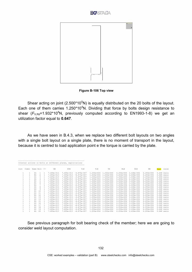
132
CSE: worked examples – validation (part B) www.steelchecks.com [email protected]
Figure B-106 Top view
Shear acting on joint (2.500*105N) is equally distributed on the 20 bolts of the layout.
Each one of them carries 1.250*104N. Dividing that force by bolts design resistance to
shear (FV,Rd=1.932*104N, previously computed according to EN1993-1-8) we get an
utilization factor equal to 0.647.
As we have seen in B.4.3, when we replace two different bolt layouts on two angles
with a single bolt layout on a single plate, there is no moment of transport in the layout,
because it is centred to load application point e the torque is carried by the plate.
--------------------------------------------------------------
Internal actions in bolts at different planes, exploitations
--------------------------------------------------------------
Inst Combi Name Bolt -?- NB NTB TuB TvB TB MuB MvB MB Expl cause
1 1 B1 1 1 7.695e-013 7.695e-013 -4.875e-007 1.250e+004 1.250e+004 6.250e+004 2.438e-006 6.250e+004 0.648 resis
1 1 B1 2 1 7.695e-013 7.695e-013 -4.875e-007 1.250e+004 1.250e+004 6.250e+004 2.438e-006 6.250e+004 0.648 resis
1 1 B1 3 1 7.695e-013 7.695e-013 -4.875e-007 1.250e+004 1.250e+004 6.250e+004 2.438e-006 6.250e+004 0.648 resis
1 1 B1 4 1 7.695e-013 7.695e-013 -4.875e-007 1.250e+004 1.250e+004 6.250e+004 2.438e-006 6.250e+004 0.648 resis
1 1 B1 5 1 7.695e-013 7.695e-013 -4.875e-007 1.250e+004 1.250e+004 6.250e+004 2.438e-006 6.250e+004 0.648 resis
1 1 B1 6 1 7.695e-013 7.695e-013 -4.875e-007 1.250e+004 1.250e+004 6.250e+004 2.438e-006 6.250e+004 0.648 resis
1 1 B1 7 1 7.695e-013 7.695e-013 -4.875e-007 1.250e+004 1.250e+004 6.250e+004 2.438e-006 6.250e+004 0.648 resis
1 1 B1 8 1 7.695e-013 7.695e-013 -4.875e-007 1.250e+004 1.250e+004 6.250e+004 2.438e-006 6.250e+004 0.648 resis
1 1 B1 9 1 7.695e-013 7.695e-013 -4.875e-007 1.250e+004 1.250e+004 6.250e+004 2.438e-006 6.250e+004 0.648 resis
1 1 B1 10 1 7.695e-013 7.695e-013 -4.875e-007 1.250e+004 1.250e+004 6.250e+004 2.438e-006 6.250e+004 0.648 resis
1 1 B1 11 1 7.695e-013 7.695e-013 -4.875e-007 1.250e+004 1.250e+004 6.250e+004 2.438e-006 6.250e+004 0.648 resis
1 1 B1 12 1 7.695e-013 7.695e-013 -4.875e-007 1.250e+004 1.250e+004 6.250e+004 2.438e-006 6.250e+004 0.648 resis
1 1 B1 13 1 7.695e-013 7.695e-013 -4.875e-007 1.250e+004 1.250e+004 6.250e+004 2.438e-006 6.250e+004 0.648 resis
1 1 B1 14 1 7.695e-013 7.695e-013 -4.875e-007 1.250e+004 1.250e+004 6.250e+004 2.438e-006 6.250e+004 0.648 resis
1 1 B1 15 1 7.695e-013 7.695e-013 -4.875e-007 1.250e+004 1.250e+004 6.250e+004 2.438e-006 6.250e+004 0.648 resis
1 1 B1 16 1 7.695e-013 7.695e-013 -4.875e-007 1.250e+004 1.250e+004 6.250e+004 2.438e-006 6.250e+004 0.648 resis
1 1 B1 17 1 7.695e-013 7.695e-013 -4.875e-007 1.250e+004 1.250e+004 6.250e+004 2.438e-006 6.250e+004 0.648 resis
1 1 B1 18 1 7.695e-013 7.695e-013 -4.875e-007 1.250e+004 1.250e+004 6.250e+004 2.438e-006 6.250e+004 0.648 resis
1 1 B1 19 1 7.695e-013 7.695e-013 -4.875e-007 1.250e+004 1.250e+004 6.250e+004 2.438e-006 6.250e+004 0.648 resis
1 1 B1 20 1 7.695e-013 7.695e-013 -4.875e-007 1.250e+004 1.250e+004 6.250e+004 2.438e-006 6.250e+004 0.648 resis
See previous paragraph for bolt bearing check of the member; here we are going to
consider weld layout computation.

133
CSE: worked examples – validation (part B) www.steelchecks.com [email protected]
In weld layout computation it is not enough to consider only the applied shear, but
also a moment due to the offset, often neglected in manual computation. This moment is
always computed by CSE.
------------------------------------------
Overall internal actions over Weld Layouts
------------------------------------------
Id Inst Combi NT TuT TvT MtT MuT MvT
W1 1 1 8.0214e-014 9.7500e-006 -2.5000e+005 -5.0866e-014 -3.7500e+006 -1.4625e-004
W1 2 1 8.0214e-014 9.7500e-006 -2.5000e+005 -5.0866e-014 -3.7500e+006 -1.4625e-004
To cross-check CSE results, we use Saldature application againt (see A.3).
Figure B-107 Saldature application: input data
Figure B-108 Saldature application: applied loads

134
CSE: worked examples – validation (part B) www.steelchecks.com [email protected]
Figure B-109 Saldature application: welds stresses results
Values for parallel and normal n are the same computed by CSE.
------------------------------------------
Internal stresses in welds, exploitations
------------------------------------------
Inst Combi Name Weld nPer tPar tPer force Cause Ext Expl
1 1 W1 1 1.225e+001 -4.478e+001 -1.746e-009 3.939e+002 3 1 0.223
1 1 W1 2 -1.225e+001 4.478e+001 1.746e-009 3.939e+002 3 1 0.223
2 1 W1 1 1.225e+001 -4.478e+001 -1.746e-009 3.939e+002 3 1 0.223
2 1 W1 2 -1.225e+001 4.478e+001 1.746e-009 3.939e+002 3 1 0.223
Beam is not checked by CSE in this case (according to check settings). Note well:
welds check also include beam check because in welds check the weakest material of
connected objects is included.

135
CSE: worked examples – validation (part B) www.steelchecks.com [email protected]
Figure B-110 Components utilization envelope
B.5.3 Double angle cleats (connection on column flange)
Starting from the same FEM model of the previous paragraphs, a 90° rotation pf the
column about its axis was applied, before re-analysing the model and re-importing it in
CSE (model: Validation_BC_3.CSE).

136
CSE: worked examples – validation (part B) www.steelchecks.com [email protected]
Figure B-111 3D view of the model
When the connection was on column web, it was possible to discard load application
point offset (it was half of web thickness). Now the offset is half of column cross-section
height and must be considered in bolt layouts computation. Bolts on column flange cannot
be “shear only”, because the offset produces a moment of transport. The layout must be
able to carry bending via tension and compression in bolts (or via tension in bolts and
compression in bearing surface, see part C of this document).
Model data: Column: HEB260
Beam: IPE 400
Angles: 120x120x12mm
Stiffeners: thickness 20mm
Material: S235
Bolts: M16 class 8.8, 1 column and 5 rows

137
CSE: worked examples – validation (part B) www.steelchecks.com [email protected]
Figure B-112 Front view
Figure B-113 Top view (beam not displayed)

138
CSE: worked examples – validation (part B) www.steelchecks.com [email protected]
Figure B-114 Bolts numbering
Applied shear on beam middle point is 125000N (a different value was applied to
previous models). Half of the load is carried by a joint and half by the other (62500N on
each joint). Shear is transferred on column axis. The offset between column axis and
column flange external face must be considered.
We have two equal bolt layouts on column flange: they are in symmetrical conditions.
As said, the offset along beam axis produces a bending moment on column flange bolt
layouts (shear multiplied by half of column cross-section height). In addition, the offset in
normal direction (b in next figure) produces a torque in bolt layouts, carried as additional
shear by the bolts. External bolts are the most exploited ones.
Figure B-115

139
CSE: worked examples – validation (part B) www.steelchecks.com [email protected]
Consider a single bolt layout. Shear is equal to V/2=3.125*104N. Distance between
layout centre and load application point is 73.55mm, so a moment of transport computed in
a simplified way would be equal to 73.55 x 3.125x104=2.298*106Nmm. As shown in
following abstract, CSE computes a smaller value: 2.110*106Nmm (92% of simplified hand
computation).
------------------------------------------
Overall internal actions over Bolt Layouts
------------------------------------------
Id Inst Combi Sec NT TuT TvT MtT MuT MvT
B1 1 1 1 -2.2543e-006 -1.2187e-006 3.1250e+004 -2.1102e+006 4.0625e+006 -7.3675e-006
B2 1 1 1 2.2543e-006 -1.2188e-006 3.1250e+004 2.1102e+006 4.0625e+006 -7.3675e-006
The reason of the difference between simplified hand computation and CSE accurate
computation is that in simplified computations we do not consider bolts length, parasitic
bending in bolt shafts and the different planes along bolts length where forces are
transferred. Consider also that shear is not transferred to the angles in correspondence of
beam vertical middle plane, but there is a distance that reduces the total offset. For these
reasons, CSE computation is more accurate than our simplified hand computation. From
now on, we will consider moment value computed by the program.
As we previously said, there is another offset to be considered. It produces bending in
bolt layouts:
M’’ = V/2 * b’ = 3.125*106N * 130mm = 4.0625*106Nmm
where b’ is half of the height of HEB260 cross-section (column MuT in CSE output listing).
Figure B-116

140
CSE: worked examples – validation (part B) www.steelchecks.com [email protected]
Consider the forces in bolt layout plane first (Figure B-115). A force Vv parallel to the
applied shear acts on each bolt. It is equal to the load applied to the layout divided by bolts
number (5). Then there is a Vu shear normal to the previous one: it is due to layout reaction
to torque. On each bolt, this shear depends on the distance from bolt to layout centre, as
seen in previous paragraphs. Resultant force on each bolt is (v and u are bolt layout
principal axes):
22
22
,
'
5
2/
p
iuvib
J
dMVVVF
Distance between bolts is 54mm, so polar inertia moment is
Jp=2*(542x1082)=29160mm2; force in each bolt is given in following table, according to
previous formula.
di [mm] Fb,i [N]
108 1.001E+04
54 7.371E+03
0 6.250E+03
54 7.371E+03
108 1.001E+04
CSE computes the same values (column TB):
--------------------------------------------------------------
Internal actions in bolts at different planes, exploitations
--------------------------------------------------------------
Inst Combi Name Bolt -?- NB NTB TuB TvB TB MuB MvB MB Expl cause
1 1 B1 1 1 -1.499e+004 -1.499e+004 -7.816e+003 6.250e+003 1.001e+004 2.811e+003 -1.473e-006 2.811e+003 0.319 resis
1 1 B1 2 1 -7.497e+003 -7.497e+003 -3.908e+003 6.250e+003 7.371e+003 2.811e+003 -1.473e-006 2.811e+003 0.198 resis
1 1 B1 3 1 -4.509e-007 -4.509e-007 -2.437e-007 6.250e+003 6.250e+003 2.811e+003 -1.473e-006 2.811e+003 0.102 resis
1 1 B1 4 1 7.497e+003 7.497e+003 3.908e+003 6.250e+003 7.371e+003 2.811e+003 -1.473e-006 2.811e+003 0.198 resis
1 1 B1 5 1 1.499e+004 1.499e+004 7.816e+003 6.250e+003 1.001e+004 2.811e+003 -1.473e-006 2.811e+003 0.319 resis
1 1 B2 1 1 -1.499e+004 -1.499e+004 7.816e+003 6.250e+003 1.001e+004 2.811e+003 -1.473e-006 2.811e+003 0.319 resis
1 1 B2 2 1 -7.497e+003 -7.497e+003 3.908e+003 6.250e+003 7.371e+003 2.811e+003 -1.473e-006 2.811e+003 0.198 resis
1 1 B2 3 1 4.509e-007 4.509e-007 -2.438e-007 6.250e+003 6.250e+003 2.811e+003 -1.473e-006 2.811e+003 0.102 resis
1 1 B2 4 1 7.497e+003 7.497e+003 -3.908e+003 6.250e+003 7.371e+003 2.811e+003 -1.473e-006 2.811e+003 0.198 resis
1 1 B2 5 1 1.499e+004 1.499e+004 -7.816e+003 6.250e+003 1.001e+004 2.811e+003 -1.473e-006 2.811e+003 0.319 resis
Now consider bending due to the offset in beam axis direction (Figure B-116). Since
we are not using a bearing surface here (see part C for this aspect), bending in the layout
produces tension or compression in bolts. To compute axial force in bolts, we need to
compute bolt layout inertia moment about considered axis (inertia moment per area unit). It
is equal to the sum of two components: the first one is the sum of squared distances from
each bolt to layout centre; the second one is the inertia moment (per area unit) of single
bolts. We have:
Jtot=Ju+5Jb
where

141
CSE: worked examples – validation (part B) www.steelchecks.com [email protected]
22222 2916010825420 mmdJ iu
For M18 bolts: r=9mm and Ab=254.4mm2, so:
2
2
44
2.205.2544
91
4
mm
mm
mm
A
rJ
b
b
Total inertia moment is:
222 2.292612.205291695 mmmmmmJJJ butot
Axial force in each bolt is:
i
tot
i dJ
MN
''
Central bolt has no axial force (d=0mm); we have two bolts in compression (d=54mm
and d=108mm) and two bolts in tension, with the same distances. We have:
Nmmmm
NmmNd
4
2
6
108 10499.11082.29261
100625.4
Nmmmm
NmmNd
3
2
6
54 10497.7542.29261
100625.4
CSE computes the same values (column NB = NTB since there is no preload):
--------------------------------------------------------------
Internal actions in bolts at different planes, exploitations
--------------------------------------------------------------
Inst Combi Name Bolt -?- NB NTB TuB TvB TB MuB MvB MB Expl cause
1 1 B1 1 1 -1.499e+004 -1.499e+004 -7.816e+003 6.250e+003 1.001e+004 2.811e+003 -1.473e-006 2.811e+003 0.319 resis
1 1 B1 2 1 -7.497e+003 -7.497e+003 -3.908e+003 6.250e+003 7.371e+003 2.811e+003 -1.473e-006 2.811e+003 0.198 resis
1 1 B1 3 1 -4.509e-007 -4.509e-007 -2.437e-007 6.250e+003 6.250e+003 2.811e+003 -1.473e-006 2.811e+003 0.102 resis
1 1 B1 4 1 7.497e+003 7.497e+003 3.908e+003 6.250e+003 7.371e+003 2.811e+003 -1.473e-006 2.811e+003 0.198 resis
1 1 B1 5 1 1.499e+004 1.499e+004 7.816e+003 6.250e+003 1.001e+004 2.811e+003 -1.473e-006 2.811e+003 0.319 resis
Bolts utilization factor computation has been already treated in detail in previous
paragraphs. Let’s go on with beam web bolt layout computation.
Beam web bolt layout is “shear only”. A shear equal to applied force acts on it,
together with a moment of transport equal to shear by distance from layout centre to
column axis (M’=V*b). In Figure B-118 are shown the components of total shear force on
each bolt. Since we have 2 check sections for the bolts, in each section the shear is half of
the applied one.

142
CSE: worked examples – validation (part B) www.steelchecks.com [email protected]
Figure B-117 Moment of transport M’=V*b
Figure B-118

143
CSE: worked examples – validation (part B) www.steelchecks.com [email protected]
Figure B-119
Distance b is 199.25mm, as shown in previous figure. Moment is:
M’ = 3.125*104N * 199.25mm = 6.226*106Nmm
CSE computes the same value (MtT).
------------------------------------------
Overall internal actions over Bolt Layouts
------------------------------------------
Id Inst Combi Sec NT TuT TvT MtT MuT MvT
B1 1 1 1 -2.2543e-006 -1.2187e-006 3.1250e+004 -2.1102e+006 4.0625e+006 -7.3675e-006
B2 1 1 1 2.2543e-006 -1.2188e-006 3.1250e+004 2.1102e+006 4.0625e+006 -7.3675e-006
B3 1 1 1 -1.2187e-006 -2.2543e-006 -3.1250e+004 6.2266e+006 5.3846e+004 -2.3314e-004
B3 1 1 2 1.2187e-006 -2.2543e-006 3.1250e+004 -6.2266e+006 5.3846e+004 2.3314e-004
Forces composition is the same done for column flange bolt layout. Bolt distances
and layout intertia moment Jp are the same. Using current shear and moment values, we
have:
22
,
'
5
2/
p
iib
J
dMVV

144
CSE: worked examples – validation (part B) www.steelchecks.com [email protected]
di [mm] Tb,i [N]
108 2.389E+04
54 1.312E+04
0 6.250E+03
54 1.312E+04
108 2.389E+04
For example, considering one of the external bolts (d=108mm from layout centre) we have:
Nmm
mmNmmNF mmb
4
2
2
62
4
108, 10389.229160
10810226.6
5
10125.3
CSE computes the same values (TB).
--------------------------------------------------------------
Internal actions in bolts at different planes, exploitations
--------------------------------------------------------------
Inst Combi Name Bolt -?- NB NTB TuB TvB TB MuB MvB MB Expl cause
1 1 B3 1 1 -2.437e-007 -2.437e-007 2.306e+004 -6.250e+003 2.389e+004 1.077e+004 -4.663e-005 1.077e+004 0.391
1 1 B3 1 2 2.437e-007 2.437e-007 -2.306e+004 6.250e+003 2.389e+004 1.077e+004 4.663e-005 1.077e+004 0.391 resis
1 1 B3 2 1 -2.437e-007 -2.437e-007 1.153e+004 -6.250e+003 1.312e+004 1.077e+004 -4.663e-005 1.077e+004 0.215
1 1 B3 2 2 2.437e-007 2.437e-007 -1.153e+004 6.250e+003 1.312e+004 1.077e+004 4.663e-005 1.077e+004 0.215 resis
1 1 B3 3 1 -2.437e-007 -2.437e-007 -4.509e-007 -6.250e+003 6.250e+003 1.077e+004 -4.663e-005 1.077e+004 0.102
1 1 B3 3 2 2.437e-007 2.437e-007 -4.509e-007 6.250e+003 6.250e+003 1.077e+004 4.663e-005 1.077e+004 0.102 resis
1 1 B3 4 1 -2.437e-007 -2.437e-007 -1.153e+004 -6.250e+003 1.312e+004 1.077e+004 -4.663e-005 1.077e+004 0.215 resis
1 1 B3 4 2 2.437e-007 2.437e-007 1.153e+004 6.250e+003 1.312e+004 1.077e+004 4.663e-005 1.077e+004 0.215
1 1 B3 5 1 -2.437e-007 -2.437e-007 -2.306e+004 -6.250e+003 2.389e+004 1.077e+004 -4.663e-005 1.077e+004 0.391 resis
1 1 B3 5 2 2.437e-007 2.437e-007 2.306e+004 6.250e+003 2.389e+004 1.077e+004 4.663e-005 1.077e+004 0.391
Figure B-120 Components utilization envelope
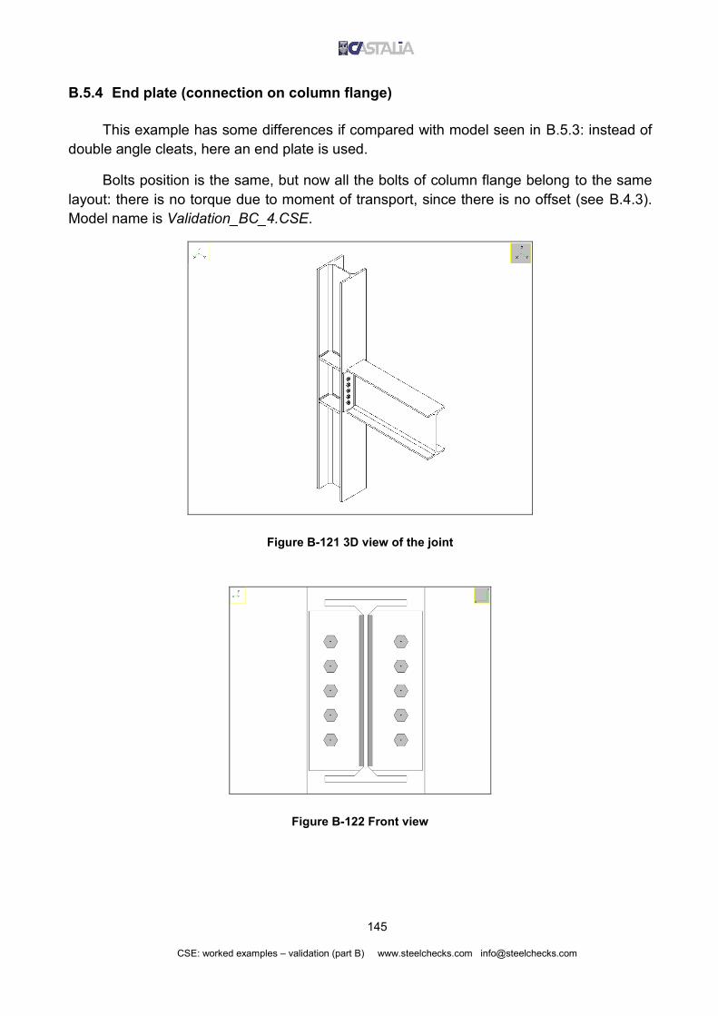
145
CSE: worked examples – validation (part B) www.steelchecks.com [email protected]
B.5.4 End plate (connection on column flange)
This example has some differences if compared with model seen in B.5.3: instead of
double angle cleats, here an end plate is used.
Bolts position is the same, but now all the bolts of column flange belong to the same
layout: there is no torque due to moment of transport, since there is no offset (see B.4.3).
Model name is Validation_BC_4.CSE.
Figure B-121 3D view of the joint
Figure B-122 Front view

146
CSE: worked examples – validation (part B) www.steelchecks.com [email protected]
Figure B-123 Side view
Figure B-124 Detail: end plate welded on beam
Model data: Material: S235
Column: HEB260
Beam: IPE 400
Plate 250x350x12mm
Stiffeners: thickness 20mm
Bolts: M16 class 8.8 (2 columns, 5 rows)
Fillet welds on beam web: length 331mm, throat section 7.071mm
As said, here there is no torque on bolt layout: shear on each bolt is equal to total
shear divided by bolts number: 62500N/10=6250N (column TB in following CSE abstract).

147
CSE: worked examples – validation (part B) www.steelchecks.com [email protected]
In addition, there are axial forces in bolts equal to those computed in previous
paragraph, since offset along beam axis and applied force are the same (column NTB in the
abstract).
--------------------------------------------------------------
Internal actions in bolts at different planes, exploitations
--------------------------------------------------------------
Inst Combi Name Bolt -?- NB NTB TuB TvB TB MuB MvB MB Expl cause
1 1 B1 1 1 1.499e+004 1.499e+004 2.438e-007 -6.250e+003 6.250e+003 -2.811e+003 -1.063e-007 2.811e+003 0.257 resis
1 1 B1 2 1 1.499e+004 1.499e+004 2.438e-007 -6.250e+003 6.250e+003 -2.811e+003 -1.063e-007 2.811e+003 0.257 resis
1 1 B1 3 1 7.497e+003 7.497e+003 2.438e-007 -6.250e+003 6.250e+003 -2.811e+003 -1.063e-007 2.811e+003 0.180 resis
1 1 B1 4 1 7.497e+003 7.497e+003 2.438e-007 -6.250e+003 6.250e+003 -2.811e+003 -1.063e-007 2.811e+003 0.180 resis
1 1 B1 5 1 -4.072e-007 -4.072e-007 2.438e-007 -6.250e+003 6.250e+003 -2.811e+003 -1.063e-007 2.811e+003 0.102 resis
1 1 B1 6 1 4.072e-007 4.072e-007 2.438e-007 -6.250e+003 6.250e+003 -2.811e+003 -1.063e-007 2.811e+003 0.102 resis
1 1 B1 7 1 -7.497e+003 -7.497e+003 2.438e-007 -6.250e+003 6.250e+003 -2.811e+003 -1.063e-007 2.811e+003 0.180 resis
1 1 B1 8 1 -7.497e+003 -7.497e+003 2.438e-007 -6.250e+003 6.250e+003 -2.811e+003 -1.063e-007 2.811e+003 0.180 resis
1 1 B1 9 1 -1.499e+004 -1.499e+004 2.438e-007 -6.250e+003 6.250e+003 -2.811e+003 -1.063e-007 2.811e+003 0.257 resis
1 1 B1 10 1 -1.499e+004 -1.499e+004 2.438e-007 -6.250e+003 6.250e+003 -2.811e+003 -1.063e-007 2.811e+003 0.257 resis
Now consider fillet weld layout. In addition to the applied shear, there bending
moment due to the offset between weld layout and column axis. Distance is equal to half of
HEB260 shape plus plate thickness.
d = 260mm / 2 + 12mm = 142mm
M = 62500N * 142mm = 8875000Nmm
The same moment is computed by CSE (MuT); TvT is applied shear divided by bolts
number.
------------------------------------------
Overall internal actions over Weld Layouts
------------------------------------------
Id Inst Combi NT TuT TvT MtT MuT MvT
W1 1 1 -0.0000e+000 -2.4375e-006 6.2500e+004 -0.0000e+000 8.8750e+006 3.4612e-004
To compute stress in fillet welds, we use Saldature application again (see A.3).

148
CSE: worked examples – validation (part B) www.steelchecks.com [email protected]
Figure B-125 Saldature application: input data
Figure B-126 Saldature application: applied loads
Figure B-127 Saldature application: welds stresses results
CSE results are the same.

149
CSE: worked examples – validation (part B) www.steelchecks.com [email protected]
------------------------------------------
Internal stresses in welds, exploitations
------------------------------------------
Inst Combi Name Weld nPer tPar tPer force Cause Ext Expl
1 1 W1 1 -3.437e+001 1.335e+001 5.207e-010 2.607e+002 2 1 0.177
1 1 W1 2 3.437e+001 -1.335e+001 -5.207e-010 2.607e+002 2 1 0.177
Figure B-128 Components utilization envelope

150
CSE: worked examples – validation (part B) www.steelchecks.com [email protected]
B.6 CONSTRAINTS
B.6.1 Column base
B.6.1.1 Introduction
Consider a column base joint. In order to validate also irregular bolt layout positions,
apply a =5.3° rotation to a four rows per 2 columns layout. Of course this is not a typical
or common condition, but it is useful to validate CSE computations in “strange” situations.
Model is Validation_CB_1.CSE; material is S235 for member and base plate. Note
well: anchor bolts pull-out check will be validated in part C, as well as bearing pressure
check. Note well: bolts compression is not included in check settings, for this model:
compression is computed, but not used for resistance checks.
Figure B-129 3D view of the joint

151
CSE: worked examples – validation (part B) www.steelchecks.com [email protected]
Figure B-130 Top view
Figure B-131 Side view

152
CSE: worked examples – validation (part B) www.steelchecks.com [email protected]
Figure B-132 Bolts numbering
B.6.1.2 Tension
This model was not imported from external FEM models: it was built directly in CSE.
To define check combinations, plastic limits of joint member were used (this is one of the
ways to define combinations in CSE). Using elastic limits, 24 combinations are defined for
each member, including single forces (axial force, shears, torque, bending moments) and
combinations between them (see program guide for more information). Amplification
factors can be defined for each component. Here all limits have an amplification factor
equal to 1.
First combination is tension. Plastic limit of the cross-section (HEA260, S235) is:
N+pl,Rd= A*fy=8682mm2 * 235N/mm2=2.0403*106N
Next figures show bolt layout geometry.

153
CSE: worked examples – validation (part B) www.steelchecks.com [email protected]
Figure B-133 Bolt layout geometry
Note well: in order to check and validate a more general condition, bolt layout and
plate have been shifted along member flanges direction (see Figure B-134, where u and v
are bolt layout principal axes).
Figure B-134 Offset between bolt layout and member centres
In this way, tension applied along column axis produces two bending moments about
bolt layout principal axes. Axial force (named simply Npl from now on) produces these
moments about u and v axes:

154
CSE: worked examples – validation (part B) www.steelchecks.com [email protected]
M’u= Npl*3.75*cos=7.618*106Nmm
M’v= Npl*3.75*sin=7.066*105Nmm
Where 3.75 is the offset in global reference system, and multiplying it bt cos or sin gives
the components along bolt layout principal axes.
Inertia moments about principal axes, according to Figure B-135, are (moments per
bolt area unit).
Ju = (dvi) = 4 * (50mm)2 + 4 * (150mm)2 = 1.000*105mm2
Jv =(dui) = 8 * (70mm)2 = 3.920*104mm2
Then we get:
M’u/Ju = 7.618*106Nmm / 1.000*105mm2 = 76.18N/mm
M’v/Jv = 7.066*105Nmm / 3.920*104mm2 = 18.03N/mm
On each bolt, resultant force is the sum of 3 components:
8
plN
i
u
u vJ
M
i
v
v uJ
M
Figure B-135 Bolts distances in bolt layout principal axes ref. system

155
CSE: worked examples – validation (part B) www.steelchecks.com [email protected]
According to distances shown in previous figure, the following tables give the
components of axial force in bolts due to bending moments, and the the total resultant
force in each bolt (layout scheme is the same of Figure B-135 and Figure B-134):
(M’u/Ju)*vi [N]
1.143E+04
1.143E+04
3.809E+03 3.809E+03
-3.809E+03 -3.809E+03
-1.143E+04 -1.143E+04
(M’v/Jv)*ui [N]
-1.262E+03
1.262E+03
-1.262E+03 1.262E+03
-1.262E+03 1.262E+03
-1.262E+03 1.262E+03
Resultant forces are:
i
v
vi
u
upl
itot uJ
Mv
J
MNF
8, [N]
2.652E+05
2.677E+05
2.576E+05 2.601E+05
2.500E+05 2.525E+05
2.423E+05 2.449E+05
Now we compute bolts design resistance to tension, as seen in B.3.
2
2
,
M
sub
Rdt
AfkF
with

156
CSE: worked examples – validation (part B) www.steelchecks.com [email protected]
k2= 0.9
fub= 800
As= 353
M2=1.25
It is Ft,Rd=2.033e+05N; utilization factors are:
Ftot,i/Ft,Rd
1.304
1.317
1.267 1.279
1.229 1.242
1.192 1.204
Unless small roundings in hand computations, we got the same results of CSE:
--------------------------------------------------------------
Internal actions in bolts at different planes, exploitations
--------------------------------------------------------------
Inst Combi Name Bolt -?- NB NTB TuB TvB TB MuB MvB MB Expl cause
1 1 B1 1 1 2.677e+005 2.677e+005 8.034e-005 -1.349e-004 1.570e-004 -2.735e+003 6.443e+002 2.810e+003 1.316 resis !!!
1 1 B1 2 1 2.652e+005 2.652e+005 8.034e-005 -1.316e-004 1.542e-004 -2.735e+003 6.443e+002 2.810e+003 1.304 resis !!!
1 1 B1 3 1 2.601e+005 2.601e+005 7.796e-005 -1.349e-004 1.558e-004 -2.735e+003 6.443e+002 2.810e+003 1.279 resis ***
1 1 B1 4 1 2.576e+005 2.576e+005 7.796e-005 -1.316e-004 1.530e-004 -2.735e+003 6.443e+002 2.810e+003 1.267 resis ***
1 1 B1 5 1 2.525e+005 2.525e+005 7.559e-005 -1.349e-004 1.547e-004 -2.735e+003 6.443e+002 2.810e+003 1.242 resis ***
1 1 B1 6 1 2.500e+005 2.500e+005 7.559e-005 -1.316e-004 1.518e-004 -2.735e+003 6.443e+002 2.810e+003 1.229 resis ***
1 1 B1 7 1 2.449e+005 2.449e+005 7.321e-005 -1.349e-004 1.535e-004 -2.735e+003 6.443e+002 2.810e+003 1.204 resis ***
1 1 B1 8 1 2.424e+005 2.424e+005 7.321e-005 -1.316e-004 1.506e-004 -2.735e+003 6.443e+002 2.810e+003 1.192 resis **

157
CSE: worked examples – validation (part B) www.steelchecks.com [email protected]
Figure B-136 Components utilization in combination 1 (tension)
Weld layout is not affected by bolt layout offset (weld layout centre lies on column
axis, so the condition is similar to the one previously computed in B.3). In order to focus on
bolt layout computation (which is rotated and has an offset), weld layout computation for
tension and for the other forces (following paragraphs) are all reported in B.6.1.8.
B.6.1.3 Shear parallel to flanges
According to EN1993-1-1, plastic shear parallel to flanges is equal to:
NmmNmmfA
VyfV
fpl
522
,
, 10878.73
/23525.5806
3
with
2
, 25.58065.122425.75.12260222 mmmmmmmmmmmmtrtbtA fwffV
Applied force lies on the line passing through bolt layout centre, since defined offset
is in y direction (Figure B-137). For that reason, there is no moment of transport in bolt
layout plane (torque), but there is a bending moment of transport causing axial force in
bolts. This axial force will not be considered in our hand computations.

158
CSE: worked examples – validation (part B) www.steelchecks.com [email protected]
Figure B-137 x-y: cross-section ref. system; u-v: bolt layout ref. sys.
Shear components parallel to u and v are:
Vu=Vsin=7.275*104N
Vv=Vcos=7.844*105N
To get forces in each bolt, divide previous values by bolts number:
Vu,bolt= Vu/8=9.094*103N
Vv,bolt= Vv/8=9.805*104N
Resultant force is:
NVVV boltvboltubolt
42
,
2
, 10847.9
Now compute bolts design resistance to shear, according to formulae used in
previous paragraphs and reported in appendix:
av 0.6
fub 800
A 452.4
M2 1.25
Fv,Rd 1.737E+05
expl 0.567
As we can see in following abstract, CSE computes this value only for 4 bolts. The
reason is that shear produces also bending (as explained previously) so bolts are also in
tension or compression. Since, according to defined check settings, compression is not

159
CSE: worked examples – validation (part B) www.steelchecks.com [email protected]
included in bolts check, CSE results for the four compressed bolts are the same of hand
computation. On the other 4 bolts, tension must be also included in checks.
--------------------------------------------------------------
Internal actions in bolts at different planes, exploitations
--------------------------------------------------------------
Inst Combi Name Bolt -?- NB NTB TuB TvB TB MuB MvB MB Expl cause
1 2 B1 1 1 -1.302e+004 -1.302e+004 -9.096e+003 -9.805e+004 9.847e+004 2.816e+003 -6.634e+002 2.893e+003 0.567 resis
1 2 B1 2 1 -1.044e+004 -1.044e+004 -9.096e+003 -9.805e+004 9.847e+004 2.816e+003 -6.634e+002 2.893e+003 0.567 resis
1 2 B1 3 1 -5.201e+003 -5.201e+003 -9.096e+003 -9.805e+004 9.847e+004 2.816e+003 -6.634e+002 2.893e+003 0.567 resis
1 2 B1 4 1 -2.621e+003 -2.621e+003 -9.096e+003 -9.805e+004 9.847e+004 2.816e+003 -6.634e+002 2.893e+003 0.567 resis
1 2 B1 5 1 2.621e+003 2.621e+003 -9.096e+003 -9.805e+004 9.847e+004 2.816e+003 -6.634e+002 2.893e+003 0.576 resis
1 2 B1 6 1 5.201e+003 5.201e+003 -9.096e+003 -9.805e+004 9.847e+004 2.816e+003 -6.634e+002 2.893e+003 0.585 resis
1 2 B1 7 1 1.044e+004 1.044e+004 -9.096e+003 -9.805e+004 9.847e+004 2.816e+003 -6.634e+002 2.893e+003 0.604 resis
1 2 B1 8 1 1.302e+004 1.302e+004 -9.096e+003 -9.805e+004 9.847e+004 2.816e+003 -6.634e+002 2.893e+003 0.613 resis
If we refine our hand computation of bolts utilization including also tension we have,
for example considering last bolt:
613.010033.24.1
10302.1
10737.1
10487.9
4.1 5
4
5
4
,
,
,
,
N
N
N
N
F
F
F
F
Rdt
Edt
Rdv
Edv
As computed by CSE.
Now consided bolt bearing on the plate according to Eurocode formulae (see
previous paragraphs or appendix). All bolts transfer the same force, so it is the position in
the layout to give different utilization values. We computed the utilization factor for one of
the bolts closest to plate edges (see Figure B-138). Note well: as previously said, CSE
gives as total utilization factor for bolt bearing the square root of the sum of the squares of
utilizations in parallel and perpendicular direction.
Fu 9.094E+03N Fv 9.805E+04N
Fb,Rd 9.792E+04N Fb,Rd 9.792E+04N
k1 2.5 k1 2.5
b 0.567 b 0.567
fu 360N/mm2 fu 360N/mm
2
d 24mm d 24mm
t 10mm t 10mm
d0 26mm d0 26mm
e1=e2 44.2mm e1=e2 44.2mm
p1 140mm p1 100mm
p2 100mm p2 140mm
explu 0.093 explv 1.001 To be on the safe side, e1 and e2 are assumed equal to minimum between e1 and e2
1.006explexplexpl 2
v
2
u

160
CSE: worked examples – validation (part B) www.steelchecks.com [email protected]
Figure B-138
Note well: see B.2.1.2.1 for a detailed step-by-step computation of design resistance
forces and utilization factors.
CSE computes the same value:
-------------------------------------------------------------
Through whose maximum exploitation is due to bearing stresses
-------------------------------------------------------------
Inst Combi Name Boltlay Bolt Extr. Sigma Sigma M Expl
1 2 P1 B1 2 1 4.103e+002 4.078e+002 1.006 *
NOTE WELL: in EN1993-1-1 the studied cases are for rectangular plates; in general,
a plate can have edges not parallel or perpendicular and plates can also have a different
number of sides: CSE always divide forces in their components along bolt layout principal
axes and uses minimum distance from the edges. This seems to be on the safe side.

161
CSE: worked examples – validation (part B) www.steelchecks.com [email protected]
Figure B-139 Components utilization in combination 2 (shear parallel to web)
B.6.1.4 Shear parallel to the web
Applied shear is Vpl,3=V=3.9017*105N, oriented along column web. Shear
components along bolt layout principal axes are:
Vu=Vcos=3.885*105N
Vv=Vsin=3.603*104N
Dividing them by bolts numbers, we get the forces on each bolt:
Vu,b= Vu/8=4.856*104N
Vv,b= Vv/8=4.504*103N
In addition, there are two further components (one in u and one in v direction) due to
the moment of transport (torque) caused by the applied shear and the offset between its
application point and bolt layout centre (d=3.75mm):
M’=V*d=1.4632*106mm

162
CSE: worked examples – validation (part B) www.steelchecks.com [email protected]
Force in u direction is equal to M’ divided by bolt layout polar inertia (Jp=1.392*105N)
and multiplied by bolt distance from layout centre, in v direction. According to each bolt
distance (see Figure B-135), we have:
(M’/Jp)*vi [N]
1.577E+03
1.58E+03
5.256E+02 5.26E+02
-5.256E+02 -5.26E+02
-1.577E+03 -1.58E+03
Resultant force in u direction on each bolt is the composition of Vu,b (the same for all
bolts) and previously computed (M’/Jp)*vi value.
Fu [N]
5.014E+04
5.014E+04
4.909E+04 4.909E+04
4.804E+04 4.804E+04
4.699E+04 4.699E+04
We make the same computations for v direction:
(M’/Jp)*ui [N]
-7.36E+02
7.36E+02
-7.36E+02 7.36E+02
-7.36E+02 7.36E+02
-7.36E+02 7.36E+02
Fv [N]
3.768E+03
5.240E+03
3.768E+03 5.240E+03

163
CSE: worked examples – validation (part B) www.steelchecks.com [email protected]
3.768E+03 5.240E+03
3.768E+03 5.240E+03
And finally we get total resultant force:
Ftot= (Fu2+Fv
2) [N]
5.028E+04
5.041E+04
4.923E+04 4.937E+04
4.819E+04 4.832E+04
4.714E+04 4.728E+04
CSE computes the same values (Fu=TuB, Fv=TvB, Ftot=TB).
--------------------------------------------------------------
Internal actions in bolts at different planes, exploitations
--------------------------------------------------------------
Inst Combi Name Bolt -?- NB NTB TuB TvB TB MuB MvB MB Expl cause
1 3 B1 1 1 6.348e+003 6.348e+003 5.014e+004 -5.241e+003 5.041e+004 1.294e+002 3.542e+003 3.544e+003 0.313 resis
1 3 B1 2 1 -7.426e+003 -7.426e+003 5.014e+004 -3.769e+003 5.028e+004 1.294e+002 3.542e+003 3.544e+003 0.289 resis
1 3 B1 3 1 6.707e+003 6.707e+003 4.909e+004 -5.241e+003 4.937e+004 1.294e+002 3.542e+003 3.544e+003 0.308 resis
1 3 B1 4 1 -7.067e+003 -7.067e+003 4.909e+004 -3.769e+003 4.923e+004 1.294e+002 3.542e+003 3.544e+003 0.283 resis
1 3 B1 5 1 7.067e+003 7.067e+003 4.804e+004 -5.241e+003 4.832e+004 1.294e+002 3.542e+003 3.544e+003 0.303 resis
1 3 B1 6 1 -6.707e+003 -6.707e+003 4.804e+004 -3.769e+003 4.819e+004 1.294e+002 3.542e+003 3.544e+003 0.277 resis
1 3 B1 7 1 7.426e+003 7.426e+003 4.699e+004 -5.241e+003 4.728e+004 1.294e+002 3.542e+003 3.544e+003 0.298 resis
1 3 B1 8 1 -6.348e+003 -6.348e+003 4.699e+004 -3.769e+003 4.714e+004 1.294e+002 3.542e+003 3.544e+003 0.271 resis
CSE also computes the axial force in the bolts due to bending moment of transport on
the layout, as seen in previous paragraph.

164
CSE: worked examples – validation (part B) www.steelchecks.com [email protected]
Figure B-140 Components utilization in combination 3 (shear parallel to the web)
B.6.1.5 Torque
Applied torque is Mt=8.527*106Nmm. The same torque is applied to bolt layout; shear
forces on bolts are computed according to what was done in previous paragraphs
(computations are not explained in detail again here; see previous computations).
Fu=(Mt/Jp)*vi [N]
9.188E+03
9.188E+03
3.063E+03 3.063E+03
-3.063E+03 -3.063E+03
-9.188E+03 -9.188E+03
Fv=(Mt/Jp)*ui [N]
-4.288E+03
4.288E+03
-4.288E+03 4.288E+03
-4.288E+03 4.288E+03

165
CSE: worked examples – validation (part B) www.steelchecks.com [email protected]
-4.288E+03 4.288E+03
Ftot= (Fu2+Fv
2) [N]
1.014E+04
1.014E+04
5.269E+03 5.269E+03
5.269E+03 5.269E+03
1.014E+04 1.014E+04
Utilization factor
0.058
0.058
0.030 0.030
0.030 0.030
0.058 0.058
CSE computes the same values:
--------------------------------------------------------------
Internal actions in bolts at different planes, exploitations
--------------------------------------------------------------
Inst Combi Name Bolt -?- NB NTB TuB TvB TB MuB MvB MB Expl cause
1 4 B1 1 1 5.878e-005 5.878e-005 9.188e+003 -4.288e+003 1.014e+004 1.198e-006 3.279e-005 3.282e-005 0.058 resis
1 4 B1 2 1 -6.876e-005 -6.876e-005 9.188e+003 4.288e+003 1.014e+004 1.198e-006 3.279e-005 3.282e-005 0.058 resis
1 4 B1 3 1 6.210e-005 6.210e-005 3.063e+003 -4.288e+003 5.269e+003 1.198e-006 3.279e-005 3.282e-005 0.030 resis
1 4 B1 4 1 -6.543e-005 -6.543e-005 3.063e+003 4.288e+003 5.269e+003 1.198e-006 3.279e-005 3.282e-005 0.030 resis
1 4 B1 5 1 6.543e-005 6.543e-005 -3.063e+003 -4.288e+003 5.269e+003 1.198e-006 3.279e-005 3.282e-005 0.030 resis
1 4 B1 6 1 -6.210e-005 -6.210e-005 -3.063e+003 4.288e+003 5.269e+003 1.198e-006 3.279e-005 3.282e-005 0.030 resis
1 4 B1 7 1 6.876e-005 6.876e-005 -9.188e+003 -4.288e+003 1.014e+004 1.198e-006 3.279e-005 3.282e-005 0.058 resis
1 4 B1 8 1 -5.878e-005 -5.878e-005 -9.188e+003 4.288e+003 1.014e+004 1.198e-006 3.279e-005 3.282e-005 0.058 resis

166
CSE: worked examples – validation (part B) www.steelchecks.com [email protected]
Figure B-141 Components utilization in combination 4 (torque)
B.6.1.6 Bending moment about strong axis
Plastic bending moment of the cross-section about strong axis is equal to
2.161*108Nmm. It is decomposed in Mu=-1.997*107Nmm and Mv=-2.152*108Nmm. Now
we are going to compute forces in each bolt, as done in B.6.1.2.
Fu=(Mu/Ju)*vi [N]
2.995E+04
2.995E+04
9.983E+03 9.983E+03
-9.983E+03 -9.983E+03
-2.995E+04 -2.995E+04
Fv=(Mv/Jv)*ui [N]
3.843E+05
-3.843E+05
3.843E+05 -3.843E+05
3.843E+05 -3.843E+05

167
CSE: worked examples – validation (part B) www.steelchecks.com [email protected]
3.843E+05 -3.843E+05
Resultant force in each bolt is (note well Fu and Fv are both axial forces; Fu is due to
Mu bending moment, Fv to Mv bending moment):
Ftot=Fu+Fv [N]
4.143E+05
-3.544E+05
3.943E+05 -3.743E+05
3.743E+05 -3.943E+05
3.544E+05 -4.143E+05
When axial force is a compression, it is not included in bolt resistance check,
according to out check settings: it is assumed that compression s carried by an area
around the bolt, involving the plate and the concrete block. For this reason, utilization
factor of compressed bolts is null. See part C for bearing surface check.
As shown in following abstract, CSE computes lower values for the forces.
--------------------------------------------------------------
Internal actions in bolts at different planes, exploitations
--------------------------------------------------------------
Inst Combi Name Bolt -?- NB NTB TuB TvB TB MuB MvB MB Expl cause
1 5 B1 1 1 -3.517e+005 -3.517e+005 -4.531e-002 5.361e-003 4.562e-002 -7.167e+003 -1.962e+005 1.963e+005 0.000 resis
1 5 B1 2 1 4.114e+005 4.114e+005 -4.531e-002 3.714e-003 4.546e-002 -7.167e+003 -1.962e+005 1.963e+005 2.023 resis !!!
1 5 B1 3 1 -3.716e+005 -3.716e+005 -4.413e-002 5.361e-003 4.446e-002 -7.167e+003 -1.962e+005 1.963e+005 0.000 resis
1 5 B1 4 1 3.915e+005 3.915e+005 -4.413e-002 3.714e-003 4.429e-002 -7.167e+003 -1.962e+005 1.963e+005 1.925 resis !!!
1 5 B1 5 1 -3.915e+005 -3.915e+005 -4.296e-002 5.361e-003 4.329e-002 -7.167e+003 -1.962e+005 1.963e+005 0.000 resis
1 5 B1 6 1 3.716e+005 3.716e+005 -4.296e-002 3.714e-003 4.312e-002 -7.167e+003 -1.962e+005 1.963e+005 1.827 resis !!!
1 5 B1 7 1 -4.114e+005 -4.114e+005 -4.178e-002 5.361e-003 4.212e-002 -7.167e+003 -1.962e+005 1.963e+005 0.000 resis
1 5 B1 8 1 3.517e+005 3.517e+005 -4.178e-002 3.714e-003 4.195e-002 -7.167e+003 -1.962e+005 1.963e+005 1.730 resis !!!
The difference is due to a lack in hand computations, which did not consider bending
in bolts shafts. We are going to refine hand computation. We previously assumed that a
distribution of forces neglecting bolts own inertia in Ju and Jv inertia moments computation.
Inertia moment of the 8 bolts is Jb=r4/4/Ab=288mm2 (inertia per area unit).
So we have:
Ju,tot=Ju+Jb=100288mm2

168
CSE: worked examples – validation (part B) www.steelchecks.com [email protected]
Jv,tot=Jv+Jb=39488mm2
Let’s compute Fu e Fv with these values:
Fu=(Mu/Ju,tot)*vi [N]
2.986E+04
2.986E+04
9.954E+03 9.954E+03
-9.954E+03 -9.954E+03
-2.986E+04 -2.986E+04
Fv=(Mv/Jv,tot)*ui [N]
3.815E+05
-3.815E+05
3.815E+05 -3.815E+05
3.815E+05 -3.815E+05
3.815E+05 -3.815E+05
Resultant forces are:
Ftot=Fu+Fv [N]
4.114E+05
-3.517E+05
3.915E+05 -3.716E+05
3.716E+05 -3.915E+05
3.517E+05 -4.114E+05
These forces are the same computed by CSE. Considering equal to zero the
utilization factors for compressed bolts (according to check settings) we can compute
utilization factors for bolts in tension, dividing previous resultant forces by bolts design resi
stance (previously computed).
Utilization factors Ftot/Ft,Rd

169
CSE: worked examples – validation (part B) www.steelchecks.com [email protected]
2.023
0
1.925 0
1.827 0
1.729 0
Figure B-142 Components utilization in combination 5 (bending about strong axis)
B.6.1.7 Bending about weak axis
Consider finally the bending moment about weak axis. Plastic moment is
1.011*108Nmm, decomposed Mu=1.007*108Nmm and Mv=-9.338*106Nmm.
We make the same computations of previous paragraph, without explaining them in
detail, but using current bending moment about weak axis.
Fu=(Mu/Ju)*vi [N]
-1.510E+05
-1.510E+05
-5.033E+04 -5.033E+04
5.033E+04 5.033E+04

170
CSE: worked examples – validation (part B) www.steelchecks.com [email protected]
1.510E+05 1.510E+05
Fv=(Mv/Jv)*ui [N]
1.667E+04
-1.667E+04
1.667E+04 -1.667E+04
1.667E+04 -1.667E+04
1.667E+04 -1.667E+04
Resultant force is:
Ftot= (Fu2+Fv
2) [N]
-1.343E+05
-1.677E+05
-3.366E+04 -6.700E+04
6.700E+04 3.366E+04
1.677E+05 1.343E+05
Utilization factors
0
0
0 0
0.330 0.166
0.825 0.661
As in previous paragraph, if hand computation is made considering Ju and Jv (without
bolts own inertia) there are some differences with CSE computation: bolts own inertia
moment should be considered to refine hand computations (see previous paragraph).
--------------------------------------------------------------
Internal actions in bolts at different planes, exploitations
--------------------------------------------------------------
Inst Combi Name Bolt -?- NB NTB TuB TvB TB MuB MvB MB Expl cause
1 6 B1 1 1 -1.671e+005 -1.671e+005 -9.918e-004 2.534e-003 2.721e-003 3.613e+004 -8.513e+003 3.712e+004 0.000 resis
1 6 B1 2 1 -1.340e+005 -1.340e+005 -9.918e-004 2.490e-003 2.680e-003 3.613e+004 -8.513e+003 3.712e+004 0.000 resis
1 6 B1 3 1 -6.674e+004 -6.674e+004 -9.604e-004 2.534e-003 2.710e-003 3.613e+004 -8.513e+003 3.712e+004 0.000 resis
1 6 B1 4 1 -3.363e+004 -3.363e+004 -9.604e-004 2.490e-003 2.669e-003 3.613e+004 -8.513e+003 3.712e+004 0.000 resis
1 6 B1 5 1 3.363e+004 3.363e+004 -9.290e-004 2.534e-003 2.699e-003 3.613e+004 -8.513e+003 3.712e+004 0.165 resis
1 6 B1 6 1 6.674e+004 6.674e+004 -9.290e-004 2.490e-003 2.658e-003 3.613e+004 -8.513e+003 3.712e+004 0.328 resis
1 6 B1 7 1 1.340e+005 1.340e+005 -8.977e-004 2.534e-003 2.688e-003 3.613e+004 -8.513e+003 3.712e+004 0.659 resis
1 6 B1 8 1 1.671e+005 1.671e+005 -8.977e-004 2.490e-003 2.647e-003 3.613e+004 -8.513e+003 3.712e+004 0.822 resis

171
CSE: worked examples – validation (part B) www.steelchecks.com [email protected]
Figure B-143 Components utilization in combination 6 (bending about weak axis)

172
CSE: worked examples – validation (part B) www.steelchecks.com [email protected]
B.6.1.8 Validation of welds stresses computation
Cross-check is made using Saldature application again (see A.3). Following image
shows the input data used.
Figure B-144 Saldature application: input data
The following is welds numbering in CSE model, needed to compare results.
Figure B-145

173
CSE: worked examples – validation (part B) www.steelchecks.com [email protected]
B.6.1.8.1 Tension
Next image shows the loads applied to weld layout in Saldature application.
Figure B-146 Saldature application: applied loads
Following image shows the stresses computed for each fillet weld by Saldature
application. Sforzi nei cordoni in Saldature. For each weld, stress value in both extremes is
given (A, B). To compare with CSE results, consider maximum value.
Figure B-147 Saldature application: stresses in welds
Stresses in CSE are the same:
------------------------------------------
Internal stresses in welds, exploitations
------------------------------------------
Inst Combi Name Weld nPer tPar tPer force Cause Ext Expl
1 1 W1 1 4.104e+002 -4.049e-008 -1.777e-007 2.902e+003 3 1 1.975 !!!
1 1 W1 2 4.104e+002 -1.777e-007 4.049e-008 2.902e+003 3 2 1.975 !!!
1 1 W1 3 4.104e+002 4.049e-008 1.777e-007 2.902e+003 3 2 1.975 !!!
1 1 W1 4 4.104e+002 4.049e-008 1.777e-007 2.902e+003 3 2 1.975 !!!
1 1 W1 5 4.104e+002 1.777e-007 -4.049e-008 2.902e+003 3 1 1.975 !!!
1 1 W1 6 4.104e+002 -4.049e-008 -1.777e-007 2.902e+003 3 1 1.975 !!!

174
CSE: worked examples – validation (part B) www.steelchecks.com [email protected]
B.6.1.8.2 Shear parallel to flanges
Figure B-148 Saldature application: applied loads
Figure B-149 Saldature application: stresses in welds
------------------------------------------
Internal stresses in welds, exploitations
------------------------------------------
Inst Combi Name Weld nPer tPar tPer force Cause Ext Expl
1 2 W1 1 3.512e-005 -1.585e+002 2.779e-007 1.121e+003 3 2 0.762
1 2 W1 2 2.050e-006 2.779e-007 1.585e+002 1.121e+003 3 1 0.762
1 2 W1 3 3.513e-005 1.585e+002 -2.779e-007 1.121e+003 3 1 0.762
1 2 W1 4 -3.512e-005 1.585e+002 -2.779e-007 1.121e+003 3 2 0.762
1 2 W1 5 -2.050e-006 -2.779e-007 -1.585e+002 1.121e+003 3 1 0.762
1 2 W1 6 -3.513e-005 -1.585e+002 2.779e-007 1.121e+003 3 1 0.762

175
CSE: worked examples – validation (part B) www.steelchecks.com [email protected]
B.6.1.8.3 Shear parallel to web
Figure B-150 Saldature application: applied loads
Figure B-151 Saldature application: stresses in welds
------------------------------------------
Internal stresses in welds, exploitations
------------------------------------------
Inst Combi Name Weld nPer tPar tPer force Cause Ext Expl
1 3 W1 1 1.934e-006 -2.953e-009 -7.849e+001 5.550e+002 3 2 0.378
1 3 W1 2 -1.502e-006 -7.849e+001 2.975e-009 5.550e+002 3 1 0.378
1 3 W1 3 -1.981e-006 2.978e-009 7.849e+001 5.550e+002 3 1 0.378
1 3 W1 4 -1.951e-006 2.978e-009 7.849e+001 5.550e+002 3 1 0.378
1 3 W1 5 1.502e-006 7.849e+001 -2.956e-009 5.550e+002 3 1 0.378
1 3 W1 6 1.964e-006 -2.953e-009 -7.849e+001 5.550e+002 3 2 0.378

176
CSE: worked examples – validation (part B) www.steelchecks.com [email protected]
B.6.1.8.4 Torque
Figure B-152 Saldature application: applied loads
Figure B-153 Saldature application: stresses in welds
------------------------------------------
Internal stresses in welds, exploitations
------------------------------------------
Inst Combi Name Weld nPer tPar tPer force Cause Ext Expl
1 4 W1 1 8.163e-009 -1.699e+001 1.949e+001 1.829e+002 3 2 0.124
1 4 W1 2 -6.255e-009 1.136e+000 -1.302e+001 9.242e+001 3 1 0.063
1 4 W1 3 -8.163e-009 -1.699e+001 -1.949e+001 1.829e+002 3 1 0.124
1 4 W1 4 -8.163e-009 -1.699e+001 1.949e+001 1.829e+002 3 2 0.124
1 4 W1 5 6.255e-009 1.136e+000 -1.302e+001 9.242e+001 3 1 0.063
1 4 W1 6 8.163e-009 -1.699e+001 -1.949e+001 1.829e+002 3 1 0.124

177
CSE: worked examples – validation (part B) www.steelchecks.com [email protected]
B.6.1.8.5 Bending moment about strong axis
Figure B-154 Saldature application: applied loads
Figure B-155 Saldature application: stresses in welds
------------------------------------------
Internal stresses in welds, exploitations
------------------------------------------
Inst Combi Name Weld nPer tPar tPer force Cause Ext Expl
1 5 W1 1 -6.458e+002 1.598e-007 8.804e-005 4.567e+003 3 1 3.107 !!!
1 5 W1 2 4.949e+002 8.804e-005 -1.598e-007 3.499e+003 3 1 2.381 !!!
1 5 W1 3 6.458e+002 -1.598e-007 -8.804e-005 4.567e+003 3 1 3.107 !!!
1 5 W1 4 6.458e+002 -1.598e-007 -8.804e-005 4.567e+003 3 1 3.107 !!!
1 5 W1 5 -4.949e+002 -8.804e-005 1.598e-007 3.499e+003 3 1 2.381 !!!
1 5 W1 6 -6.458e+002 1.598e-007 8.804e-005 4.567e+003 3 1 3.107 !!!

178
CSE: worked examples – validation (part B) www.steelchecks.com [email protected]
B.6.1.8.6 Bending moment about weak axis
Figure B-156 Saldature application: applied loads
Figure B-157 Saldature application: stresses in welds
------------------------------------------
Internal stresses in welds, exploitations
------------------------------------------
Inst Combi Name Weld nPer tPar tPer force Cause Ext Expl
1 6 W1 1 6.940e+002 1.749e-006 2.348e-006 4.907e+003 3 2 3.339 !!!
1 6 W1 2 4.045e+001 2.348e-006 -1.749e-006 2.860e+002 3 1 0.195
1 6 W1 3 6.940e+002 -1.749e-006 -2.348e-006 4.907e+003 3 1 3.339 !!!
1 6 W1 4 -6.940e+002 -1.749e-006 -2.348e-006 4.907e+003 3 2 3.339 !!!
1 6 W1 5 -4.045e+001 -2.348e-006 1.749e-006 2.860e+002 3 1 0.195
1 6 W1 6 -6.940e+002 1.749e-006 2.348e-006 4.907e+003 3 1 3.339 !!!

179
CSE: worked examples – validation (part C) www.steelchecks.com [email protected]
C. COMPONENTS CHECKS AND FLEXIBILITY INDEX

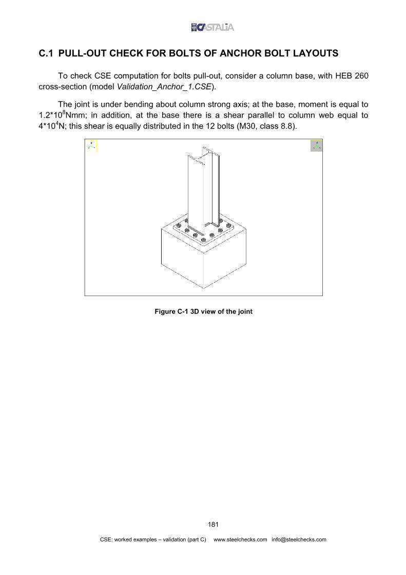
181
CSE: worked examples – validation (part C) www.steelchecks.com [email protected]
C.1 PULL-OUT CHECK FOR BOLTS OF ANCHOR BOLT LAYOUTS
To check CSE computation for bolts pull-out, consider a column base, with HEB 260
cross-section (model Validation_Anchor_1.CSE).
The joint is under bending about column strong axis; at the base, moment is equal to
1.2*108Nmm; in addition, at the base there is a shear parallel to column web equal to
4*104N; this shear is equally distributed in the 12 bolts (M30, class 8.8).
Figure C-1 3D view of the joint

182
CSE: worked examples – validation (part C) www.steelchecks.com [email protected]
Figure C-2 Anchor bolts data
As we can see in the deformed view of following figure, there are some bolts in
tension and an area in compression between base plate and constraint block. In this
model, bolts do not react to compression and bearing surface check is not investigated.

183
CSE: worked examples – validation (part C) www.steelchecks.com [email protected]
Figure C-3 Amplified deformed view (side view)
Forces distribution in bolts has been investigated in part B of this document.
Considering forces computed in each bolt by CSE, we can now compute the utilization
value for bolts pull-out check, to compare it with CSE result. Consider the bolt with the
highest tension force (bolt number 1, see NTB column in following abstract). The utilization
factor is the ration between axial force in bolt and limit force. If limit force is exceeded,
there is a pull-out.
------------------------------------------------------------------
Internal actions in bolts at different planes, utilization ratios
------------------------------------------------------------------
Inst Combi Name Bolt -?- NB NTB TuB TvB TB MuB MvB MB Expl cause
(N) (N) (N) (N) (N) ( N mm) ( N mm) ( N mm)
1 1 B1 1 1 69825.6 69825.6 3333.3 0.0 3333.3 0.0 19112.8 19112.8 1.669 pullo !!!
1 1 B1 2 1 23275.2 23275.2 3333.3 0.0 3333.3 0.0 19112.8 19112.8 0.556 pullo
1 1 B1 3 1 -23275.2 -23275.2 3333.3 0.0 3333.3 0.0 19112.8 19112.8 0.012 resis
1 1 B1 4 1 -69825.6 -69825.6 3333.3 0.0 3333.3 0.0 19112.8 19112.8 0.012 resis
1 1 B1 5 1 69825.6 69825.6 3333.3 0.0 3333.3 0.0 19112.8 19112.8 1.669 pullo !!!
1 1 B1 6 1 -69825.6 -69825.6 3333.3 0.0 3333.3 0.0 19112.8 19112.8 0.012 resis
1 1 B1 7 1 69825.6 69825.6 3333.3 0.0 3333.3 0.0 19112.8 19112.8 1.669 pullo !!!
1 1 B1 8 1 -69825.6 -69825.6 3333.3 0.0 3333.3 0.0 19112.8 19112.8 0.012 resis
1 1 B1 9 1 69825.6 69825.6 3333.3 0.0 3333.3 0.0 19112.8 19112.8 1.669 pullo !!!
1 1 B1 10 1 23275.2 23275.2 3333.3 0.0 3333.3 0.0 19112.8 19112.8 0.556 pullo
1 1 B1 11 1 -23275.2 -23275.2 3333.3 0.0 3333.3 0.0 19112.8 19112.8 0.012 resis
1 1 B1 12 1 -69825.6 -69825.6 3333.3 0.0 3333.3 0.0 19112.8 19112.8 0.012 resis
Pull-out force Fd for anchor bolts is equal to:
2
1
1
a
safety
LF
eq
d

184
CSE: worked examples – validation (part C) www.steelchecks.com [email protected]
where Leq is the equivalent length of the bars, is tangential bond stress, is bar diameter,
ais the distance from the free surface, and safety is a safety factor which is equal to 1
according to EN1993-1-8.
NmmmmNmm
Fd 9.41825)3,01(
1
1
30/5,15002
2
Utilization factor is the same computed by CSE:
669.19.41825
69830max N
N
F
NTB
d
Figure C-4 Components utilization envelope
C.2 AUTOMATIC FEM MODEL CHECK
The model used here (Validation_FEM_1.AA.P1.WSR) is similar to the one of
previous paragraph. In addition, now we include the automatic FEM model creation and
analysis of the base plate (Figure C-6).

185
CSE: worked examples – validation (part C) www.steelchecks.com [email protected]
Figure C-5 3D view of the model
Figure C-6 Settings for automatic FEM model creation
Model settings:
Plate-shell elements size on edges and weld lines: 20mm
Maximum plate-shell elements size: 20mm
Elements minimum angle: 19.8°

186
CSE: worked examples – validation (part C) www.steelchecks.com [email protected]
Node tolerance: 0.1mm (if the distance between two nodes is smaller than 0.1, nodes
are merged)
The automatically created model has the same properties (geometry and material) of
the 3D component in CSE. It has a number of load cases equal to check combinations
multiplied by jnode instances. Here we have only one combination and one instance, so
the Fem model has just one load case.
As shown in Figure C-7, each load case has nodal forces in correspondence of the
bolts and the welds which transfer forces to the plate. In addition, small nodal forces model
the compression on bearing surface (see Figure C-8, where plate shell elements are
hidden and forces length is the same, not scaled according to forces value).
Figure C-7 Base plate FEM model automatically created by CSE
Nodal constraints are needed to solve the static problem, but since the model is self-
balanced these constraints have quite null forces (the more mesh size is small, the more
constraint forces are small). As expected, nodal forces resultant is shown in Figure C-9: it
is quite null (0.02N) if compared to applied forces (bending moment is 1.2*108Nmm, shear
4*104N).

187
CSE: worked examples – validation (part C) www.steelchecks.com [email protected]
Figure C-8 Plate-shell elements hidden, nodal forces displayed with the same length
Figure C-9 Nodal forces resultant: F=0.02N
Following figures show the amplified deformed view of base plate FEM model and
Von Mises stress in plate-shell elements (in the only load case of the model).

188
CSE: worked examples – validation (part C) www.steelchecks.com [email protected]
Figure C-10 Amplified Deformed View
Figure C-11 Von Mises stresses on visible face (with interelement jumps); max value: 575.9N/mm2

189
CSE: worked examples – validation (part C) www.steelchecks.com [email protected]
Figure C-12 Von Mises stresses on hidden face (with interelement jumps); max value: 573.7N/mm2
Maximum computed value for Von Mises stress is 575.9N/mm2 on visible face. CSE
uses this value to get an utilization factor: maximum Von Mises stress is divided by
material yield stress and multiplied by M0 safety factor. This utilization factor is then
compared to the results of other checks (bolt bearing, block tear, etc.) and maximum value
is given.
Material is S235; plate thickness is 35mm<40mm so no yield stress reduction is
needed according to EN1993. Utilization factor is equal to:
451.2/235
0.1/9.575expl
2
20max,
mmN
mmN
f y
MVM
The same value is computed by CSE.
---------------------------------------------------------------------
Cleats whose worst utilization ratio is due to fem resistance checks
---------------------------------------------------------------------
Inst Combi Name VM fd Expl
( N/ mm²) ( N/ mm²)
1 1 P1 575.9 235.0 2.451 !!!

190
CSE: worked examples – validation (part C) www.steelchecks.com [email protected]
Figure C-13 Components utilization envelope
If yield stress is exceeded in some areas of the FEM model, it is up to the designer to
choose one of the following conditions:
these areas are just local peaks of stress (they can be neglected and plate can be
considered checked);
these areas are so big that plate must be considered unchecked (so stiffeners need to
be added, or plate thickness must be increased, or steel grade, etc.);
for conditions in the middle between the two previous ones, a nonlinear computation
could be needed in order to see if the plate is able to carry the whole load with some
plasticizations (elastic-perfectly plastic constitutive law).
NOTE WELL: in this model we required the automatic creation of plate FEM model
together with its automatic analysis and automatic computation of an utilization factor
according to maximum Von Mises stress; it is also possible to require the FEM model
creation only, without its analysis, in order to keep FEM results separated from other
checks results. Models can be created for one of the interfaced programs, and then
analysed with chosen program.

191
CSE: worked examples – validation (part C) www.steelchecks.com [email protected]
C.3 SLIP-RESISTANT BOLT LAYOUTS CHECK
Some modifications were done to the model seen in previous paragraphs: bolt layout
settings have been changed in order to use a slip-resistant layout (model:
Validation_Slip_1.CSE) and loads have been set to have only shear at the base (this is not
a realistic condition, but is needed to get easier and clearer hand computations).
FEM model creation is not required, and since there is not applied bending or tension,
pull-out check of bars is not relevant.
Figure C-14 3D view of the joint
The following figure shows preload and settings for slip-resistance check.

192
CSE: worked examples – validation (part C) www.steelchecks.com [email protected]
Figure C-15 Data for slip-resistance check
Kn defines the preload as a percentage of bolts ultimate load for tension. With Kn=0.7,
preload is equal to:
Fp,C = Kn * fu,b * Ares = 0.7 * 800N/mm2 * 561mm2 = 314160N
(Fi) is hole coefficient; in EN1993-1-8 it is named ks and is equal to 1 for normal
holes; (Mu) is friction coefficient, here defined equal 0.4 (class B surfaces). With previous
value, the limit shear over which slip occurs is, for a single bolt:
NNFnk
F Cp
M
sRds 114240314160
1.1
4.011,
3
,
where n=1 is the number of surfaces involved by friction (CSE automatically detects this
parameter).
Since the layout is slip-resistant, resistance check of bolts shaft under shear is not
required. We just need to check that applied shear on each bolt does not exceed limit
value Fs,Rd. Each bolt carries a shear equal to total applied shear (V) divided by bolt
number (nB). Check is:

193
CSE: worked examples – validation (part C) www.steelchecks.com [email protected]
263.0114240
12/360000/expl
,,
s N
N
F
nV
F
V
Rds
B
Rds
B
As we can see in following abstract, CSE computes slightly different values, and we will
see shortly the reason of this difference, due to simplified hand computations.
--------------------------------------------------------------
Internal actions in bolts at different planes, exploitations
--------------------------------------------------------------
Inst Combi Name Bolt -?- NB NTB TuB TvB TB MuB MvB MB Expl cause
1 1 B1 1 1 7.247e+003 3.214e+005 3.000e+004 0.000e+000 3.000e+004 0.000e+000 1.984e+003 1.984e+003 0.268 slip
1 1 B1 2 1 2.416e+003 3.166e+005 3.000e+004 0.000e+000 3.000e+004 0.000e+000 1.984e+003 1.984e+003 0.264 slip
1 1 B1 3 1 -2.416e+003 3.117e+005 3.000e+004 0.000e+000 3.000e+004 0.000e+000 1.984e+003 1.984e+003 0.263 slip
1 1 B1 4 1 -7.247e+003 3.069e+005 3.000e+004 0.000e+000 3.000e+004 0.000e+000 1.984e+003 1.984e+003 0.263 slip
1 1 B1 5 1 7.247e+003 3.214e+005 3.000e+004 0.000e+000 3.000e+004 0.000e+000 1.984e+003 1.984e+003 0.268 slip
1 1 B1 6 1 -7.247e+003 3.069e+005 3.000e+004 0.000e+000 3.000e+004 0.000e+000 1.984e+003 1.984e+003 0.263 slip
1 1 B1 7 1 7.247e+003 3.214e+005 3.000e+004 0.000e+000 3.000e+004 0.000e+000 1.984e+003 1.984e+003 0.268 slip
1 1 B1 8 1 -7.247e+003 3.069e+005 3.000e+004 0.000e+000 3.000e+004 0.000e+000 1.984e+003 1.984e+003 0.263 slip
1 1 B1 9 1 7.247e+003 3.214e+005 3.000e+004 0.000e+000 3.000e+004 0.000e+000 1.984e+003 1.984e+003 0.268 slip
1 1 B1 10 1 2.416e+003 3.166e+005 3.000e+004 0.000e+000 3.000e+004 0.000e+000 1.984e+003 1.984e+003 0.264 slip
1 1 B1 11 1 -2.416e+003 3.117e+005 3.000e+004 0.000e+000 3.000e+004 0.000e+000 1.984e+003 1.984e+003 0.263 slip
1 1 B1 12 1 -7.247e+003 3.069e+005 3.000e+004 0.000e+000 3.000e+004 0.000e+000 1.984e+003 1.984e+003 0.263 slip
The reason ot the difference between hand computation and CSE computation is that
there is not only shear in bolt layout, but also a bending moment of transport due to shear
multiplied by a lever arm. This lever arm is the offset between shear application point
(lower extreme of the column) and friction surface (lower face of the plate on upper face of
contraint block): in practice, it is equal to plate thickness. See the deformed view in Figure
C-16 and the offset in Figure C-17.
Figure C-16 Amplified deformed view: shift plus bending

194
CSE: worked examples – validation (part C) www.steelchecks.com [email protected]
Figure C-17
The following abstract show internal forces in bolt layout.
------------------------------------------
Overall internal actions over Bolt Layouts
------------------------------------------
Id Inst Combi Sec NT TuT TvT MtT MuT MvT
B1 1 1 1 0.0000e+000 3.6000e+005 0.0000e+000 0.0000e+000 0.0000e+000 1.2600e+007
If we divide the bending moment computed by CSE (MvT in the abstract) by the
applied shear, we get exactly the thickness of the plate:
1.26*107Nmm / 3.6*105N = 35mm
This bending moment of transport produces an additional tension in bolts, that must
be considered when computing limit shear value for slip, according to the following formula
of EN1993-1-8.
3
,,
,
)8,0(
M
EdtCps
Rds
FFnkF
Consider again the abstract previously shown:
--------------------------------------------------------------
Internal actions in bolts at different planes, exploitations
--------------------------------------------------------------
Inst Combi Name Bolt -?- NB NTB TuB TvB TB MuB MvB MB Expl cause
1 1 B1 1 1 7.247e+003 3.214e+005 3.000e+004 0.000e+000 3.000e+004 0.000e+000 1.984e+003 1.984e+003 0.268 slip
1 1 B1 2 1 2.416e+003 3.166e+005 3.000e+004 0.000e+000 3.000e+004 0.000e+000 1.984e+003 1.984e+003 0.264 slip
1 1 B1 3 1 -2.416e+003 3.117e+005 3.000e+004 0.000e+000 3.000e+004 0.000e+000 1.984e+003 1.984e+003 0.263 slip
1 1 B1 4 1 -7.247e+003 3.069e+005 3.000e+004 0.000e+000 3.000e+004 0.000e+000 1.984e+003 1.984e+003 0.263 slip
1 1 B1 5 1 7.247e+003 3.214e+005 3.000e+004 0.000e+000 3.000e+004 0.000e+000 1.984e+003 1.984e+003 0.268 slip
1 1 B1 6 1 -7.247e+003 3.069e+005 3.000e+004 0.000e+000 3.000e+004 0.000e+000 1.984e+003 1.984e+003 0.263 slip
1 1 B1 7 1 7.247e+003 3.214e+005 3.000e+004 0.000e+000 3.000e+004 0.000e+000 1.984e+003 1.984e+003 0.268 slip
1 1 B1 8 1 -7.247e+003 3.069e+005 3.000e+004 0.000e+000 3.000e+004 0.000e+000 1.984e+003 1.984e+003 0.263 slip
1 1 B1 9 1 7.247e+003 3.214e+005 3.000e+004 0.000e+000 3.000e+004 0.000e+000 1.984e+003 1.984e+003 0.268 slip
1 1 B1 10 1 2.416e+003 3.166e+005 3.000e+004 0.000e+000 3.000e+004 0.000e+000 1.984e+003 1.984e+003 0.264 slip
1 1 B1 11 1 -2.416e+003 3.117e+005 3.000e+004 0.000e+000 3.000e+004 0.000e+000 1.984e+003 1.984e+003 0.263 slip
1 1 B1 12 1 -7.247e+003 3.069e+005 3.000e+004 0.000e+000 3.000e+004 0.000e+000 1.984e+003 1.984e+003 0.263 slip

195
CSE: worked examples – validation (part C) www.steelchecks.com [email protected]
In column NB we have the axial force in bolts (NTB column is the sum of NB and
preload). Some bolts are subjected to tension, others to compression, according to their
position In the layout. For this reason, slip check on different bolts must give different
results, and maximum utilization factor for slip should be on the bolt with maximum tension
(bolt number 1, with NB = +7247N). If we compute limit shear for this bolt, we get:
NNFFnk
FM
EdtCps
Rds 1121321.1
)72478.0314160(4.011)8,0(
3
,,
,
And associated utilization factor is:
268.0112132
30000expl
,
s N
N
F
V
Rds
B
which is the same value computed by CSE.
NOTE WELL: tension in bolts produces a reduction of limit shear value, but compression in
bolts does not increase limit shear value (being on the safe side).
C.4 MEMBERS NET SECTIONS CHECK
CSE automatically recognizes reductions of members gross cross-section due to bolt
holes, notches, bevels, cuts or other work processes, scanning the member along its axis.
In addition, CSE computes the properties of these cross sections.
If user requires it, the program automatically checks the resistance of all the net
sections found, in each load combination and in each jnode instance, considering the
forces acting on a given section (only the forces transferred by bolts and welds which are
beyond considered section).
If net sections check gives maximum utilization factor (amont bolt bearing, bolt
tearing, user’s checks, FEM check, etc.), this utilization factor is printed in the output listing
and shown at screen.
Consider a single sided beam to beam joint, with a hinged supported beam
connected using an end plate (model Validation_NetSections_1.CSE). Supported beam is
double notched (see Figure C-19) and there are not bolt holes. We have net sections in
correspondence of the notches.

196
CSE: worked examples – validation (part C) www.steelchecks.com [email protected]
Figure C-18 3D view of the model
Figure C-19 Detail
In imported FEM model there is a force in supported beam middle point (Figure
C-20). Since it is hinged moment distribution will be triangular (Figure C-21).

197
CSE: worked examples – validation (part C) www.steelchecks.com [email protected]
Figure C-20 Imported FEM model
Distance between the two nodes of supported beam is 1000mm, but there is a rigid
offset equal to 12.8mm in the FEM model, in order to subtract plate thickness and half ow
supporting beam web thickness from member total length. Supported member total length
is L=1000mm-12.8mm=987.2mm.
Internal shear in supported beam is equal to:
V = F/2 = 100000N / 2 = 50000N
Bending moment is null at the extremes; in the middle it is equal to:
Mmax = V * (L/2) = 50000N * 987.2mm / 2 = =2.468*107Nmm
Figure C-21 Internal forces in FEM model

198
CSE: worked examples – validation (part C) www.steelchecks.com [email protected]
CSE found two net sections in supported member (see Figure C-22 and Figure C-23). The
position of these net sections along member axis is shown in Figure C-24: they are at 1mm
from section change.
Figure C-22 Member m2, net section 1
Figure C-23 Member m2, net section 2

199
CSE: worked examples – validation (part C) www.steelchecks.com [email protected]
Figure C-24 Net sections position
CSE gives net sections properties, but now we are going to compute them
independently from the program. We need sections area and bending moduli. Web
thickness is 5.6mm; net section height is equal to 139mm (Figure C-24). Area is:
Anet = 139mm * 5.6mm = 778.4mm
Shear check for a rectangular section is:
vnet
Edv
fA
Vl
exp
where
22
0 /7.1353/1//2353// mmNmmNff Myv
so:
5.0 473.0/7.1354.778
50000expl
2v
mmNmm
N
Since utilization factor for shear is less than 0.5, resistance to bending has not to be
reduced (note well: here there is not axial force). Net section inertia moment about
member strong axis is:
J = 5.6mm * (139mm)3 /12 = 1253288.9mm4

200
CSE: worked examples – validation (part C) www.steelchecks.com [email protected]
Bending modulus about the same axis is:
W = J / (L/2) = 1253288.9mm4 * 2 / 139mm = 18032.93mm3
The same values are computed by CSE:
Figure C-25 Net section properties
As previously said, bending moment has a triangular shape.
Figure C-26 Bending model (imported FEM model from Sargon)
Referring to Figure C-27, moment is quite null in section 1; in section number 2,
bending moment is equal to:

201
CSE: worked examples – validation (part C) www.steelchecks.com [email protected]
Nmmmm
mmNmm
L
dM 67
max 10950.12/2.987
3910468.2
2/
Figure C-27
Stress to be considered in bending check is:
22
0
/2351
/235mmN
mmNff
M
y
d
For net section 2, utilization factor for bending is:
v23
6
M expl 460.0/23593.18032
10950.1expl
mmNmm
Nmm
fW
M
d
Maximum utilization factor is due to shear and is equal to 0.473. CSE computes the
same value:
-----------------------------------------------------------------
Members whose relevant exploitation is due to net sections check
-----------------------------------------------------------------
Inst Combi Name Sect N T2 T3 M1 M2 M3 fd Expl
1 1 m2 2 -3.203e-013 -8.176e-012 -5.000e+004 0.000e+000 -1.950e+006 1.994e-010 2.350e+002 0.473
Following figure show CSE results for most critical net section.

202
CSE: worked examples – validation (part C) www.steelchecks.com [email protected]
Figure C-28 Net section results
Figure C-29 Components utilization envelope

203
CSE: worked examples – validation (part C) www.steelchecks.com [email protected]
C.5 SIMPLIFIED CHECKS FOR CLEATS (STANDARD SECTIONS)
In model Validation_Cleat_1.CSE, which is shown in following figures, the automatic
simplified check for cleats standard sections have been done by CSE. Standard sections
are relevant check sections depending on component type, as explained later.
Figure C-30 3D view of the joint
Figure C-31 Detail of the connection
Slave member is a truss, so axial force only is transferred from it to master member
(tension, in this case). Applied force produces shear force on slave web bolt layout and

204
CSE: worked examples – validation (part C) www.steelchecks.com [email protected]
axial force in master flange bolt layout. In addition, there is a moment of transport due to
the offset between applied load and bolts. This actions are transferred to the angle cleats.
Figure C-32 Amplified deformed view
CSE checks the resistance of some sections depending on cleat shape. In case of
angles, two sections are checked; those sections, which are shown in following figure, are
checked through an equivalent beam model. Note well: since we required to neglect bolt
shafts bending from resistance checks, it has not to be considered in cleats (but also
members) check. CSE computes bending in shafts anyway, but user can require to not
consider it during the checks.
Figure C-33 Check sections S1 and S2
Forces acting on section S1 are those of extreme 3 of bolt layout B1; forces acting on
section S2 are those of extreme 1 of bolt layout B3. Considering the following CSE
abstract, forces computed on involved bolt layouts extremes are:

205
CSE: worked examples – validation (part C) www.steelchecks.com [email protected]
--------------------------------------------------------------------
Forces acting over bolt layouts at different extremes, global system
--------------------------------------------------------------------
Id Inst Combi Ext Fx Fy Fz Mx My Mz
B1 1 1 1 4.1856e+004 -1.4881e-005 7.4475e+001 -1.0906e-004 1.1348e+006 5.2621e-005
B1 1 1 2 -8.3712e+004 3.2445e-006 -7.1054e-014 1.7462e-009 1.8626e-009 -2.3238e-005
B1 1 1 3 4.1856e+004 1.1636e-005 -7.4475e+001 -1.2429e-004 -1.1348e+006 -2.9383e-005
B2 1 1 1 1.6125e-005 7.4475e+001 4.1856e+004 8.6027e+005 9.7767e-004 1.6226e-004
B2 1 1 2 -1.6125e-005 -7.4475e+001 -4.1856e+004 -8.5926e+005 -1.1954e-003 -1.6226e-004
B3 1 1 1 7.0803e-006 -7.4475e+001 4.1856e+004 -8.6027e+005 1.1791e-003 8.7227e-004
B3 1 1 2 -7.0803e-006 7.4475e+001 -4.1856e+004 8.5926e+005 -1.2747e-003 -8.7227e-004
Section S1: Axial force equal to 4.1856*104N (Fx in the abstract)
Shear equal to –7.4475*101N (Fz)
Bending moment equal to –1.1348*106Nmm (My)
Section S2: Axial force equal to –7.4475*101N (Fy)
Shear equal to 4.1856*104N (Fz)
Bending moment equal to –8.6027*105Nmm (Mx)
As we can see, CSE computes a force normal to applied load in both extremes (Fz in
B1 - extreme 3, which is axial force in B1 bolts, and Fy in B3 – extreme 1, which produces
shear in B3 bolts. These forces are usually not considered in hand computations, but they
are present and CSE computes them (see part B for forces distribution in joiners).
An axial force in bolt layout produces shear in corresponding net section and a shear
in a bolt layout produces an axial force in corresponding section (see next figure).
Check sections have a rectangular section with these sizes: base is equal to angle
(12mm), height is equal to angle length (159mm).

206
CSE: worked examples – validation (part C) www.steelchecks.com [email protected]
Figure C-34 Forces in bolt layouts and corresponding forces in check sections
Forces acting on check sections are printed in the following table:
Check section S1 Check section S2
FxS1 = - FxB1 = 41856N FyS2 = - FyB3 = 74.475N
FzS1 = - FzB1 = 74.475N FzS2 = - FzB3 = 41856N
MS1 = FzB1 * b = 2290Nmm MS2 = FzB3 * b = 1287000Nmm
Check sections area A = 12mm x 159mm = 1908mm2. Inertia modulus about the
axis subjected to bending, and then its corresponding modulus, are:
J = 159mm * 123mm / 12 = 22896mm4
W = J / t / 2 = 22896mm4 / 6mm = 3816mm3
Material is S275 abbiamo, so we have:
Mres = fy * W = 275N/mm2 * 3816mm3 = 1574100Nmm
Nres = fy * A = 275N/mm2 * 1908mm2 = 52470N
S1 check for axial force and bending is:
081.01574100
2290
524700
41856expl
MNS1 Nmm
Nmm
N
N
M
M
N
N
resres
S2 check for axial force and bending is:

207
CSE: worked examples – validation (part C) www.steelchecks.com [email protected]
818.01574100
1287000
524700
48.74expl
MNS2 Nmm
Nmm
N
N
M
M
N
N
resres
S2 check for shear is (S2 is the one with maximum shear):
138.03//2751908
41856
3/expl
22S2V
mmNmm
N
Af
V
y
Maximum utilization factor is 0.818 for section S2, due to bending plus axial force.
CSE computes the same result, as we will see later.
In addition to previous check sections, CSE considers also the mean section of the
cleat along its extrusion axis, subjected only to the forces acting beyond that section (see
Figure C-35, right, check section is in black). Check section is subjected only to the forces
of the two upper bolts (displayed in red and yellow). Forces and moments in bolts shaft
must be in equilibrium (Figure C-36) so action must produce a null resultant (obviously
there is no torsion on the cleat). Since check settings neglect bending moment on bolt
shafts, the forces would produce a torsion in the net section, but this torsion is not present
in the component: for this reason, torsion check was not included in cleat check. Since
there is no shear, axial force or bending moment in considered check section, its utilization
factor is null, and previously computed value (0.818) results as maximum utilization for the
component.
Figure C-35

208
CSE: worked examples – validation (part C) www.steelchecks.com [email protected]
Figure C-36
CSE computes the same value.
-------------------------------------------------------------------------------
Throughs whose worst exploitation is due to simplified "beam" resistance checks
-------------------------------------------------------------------------------
Inst Combi Name Sect N T2 T3 M1 M2 M3 Expl
1 1 L1 2 -7.448e+001 -7.080e-006 4.186e+004 1.209e-003 -1.287e+006 6.546e-004 0.818
1 1 L2 2 -7.448e+001 1.613e-005 4.186e+004 -1.064e-003 -1.287e+006 6.581e-004 0.818
Figure C-37 Components utilization envelope

209
CSE: worked examples – validation (part C) www.steelchecks.com [email protected]
C.6 BEARING SURFACE CHECK
C.6.1 No-tension parabola-rectangle constitutive law
C.6.1.1 Combined compression and bending moment
We prepared a model of a column base in order to check the bearing stresses on
concrete block with no-tension parabola-rectangle constitutive law (model
Validation_Bearing_1.CSE).
The model is shown in following figure. Resistance check for bolts, welds, etc. see
part B of the document, where these aspects have been studied in detail. Here we will
consider the check of bearing surface, which is the area in compression between base
plate and concrete block.
A specific non-linear algorithm (derived from those utilised in non-linear computations
of reinforced concrete cross-sections) is used by CSE in order to find elastic neutral axis
position and the compressive stresses acting over the reactive part of the bearing surface,
as well as the tensile stresses in the tensile bolts.
Figure C-38 3D view of the joint
Bolt layout geometry and properties are shown in next image. Bearing surface is
equal to base plate footprint (600x600mm). Bearing surface check will be associated to the
constraint block.

210
CSE: worked examples – validation (part C) www.steelchecks.com [email protected]
Figure C-39 Bolt layout data
NOTE WELL: here the whole plate footprint was assumed as bearing surface; in CSE it is also
possible to define bearing surfaces in a general way, for example adding a border to column footprint, with
border size depending on plate material, plate thickness and constraint block material, according to the
Standard. If there are stiffeners, their bordered footprint can be included too.
Bolts total area is considered in the check (not threaded area, this is a choice in
check settings) and single bolts own inertia is not considered in bolt layout total inertia
moment (this is another check setting). To cross-check CSE results, we will use the
software Lisa (see A.3).
The constitutive law defined in CSE for constraint block is shown in next image. It is a
no-tension parabola-rectangle constitutive law, defined by point (s1, e1) (stress,
deformation) and ultimate deformation eu. M factor is defined equal to 1.6 because this
parameter is fixed in Lisa© to that value, and we need the same input to compare results.

211
CSE: worked examples – validation (part C) www.steelchecks.com [email protected]
Figure C-40 Bearing surface constitutive law (units: N, mm)
Forces at column lower extreme: - compression = 3*105N;
- bending about strong axis = 8*107Nmm
The following figure shows bearing surface results computed by CSE.

212
CSE: worked examples – validation (part C) www.steelchecks.com [email protected]
Figure C-41 Bearing surface check results
c- maximum compression stress in concrete block: -2.986N/mm2
b+ maximum stress in bolts: +28.2N/mm2
b- minimum stress in bolts: -33.0N/mm2
A computation with the same loads and geometry was done with Lisa©, through a
limit state computation according to DM2006, Sections II and III (Italian Standard). The
following listing reports computed results for maximum positive normal stress in bolts and
compression stress in concrete. The figure of defined geometry is given after the listing.
Programma LISA Ver. 3.5 Copyright © Castalia s.r.l.
(http://www.castaliaweb.com)
Coordinate dei nodi della sezione:
X [cm] Y [cm]
1* 30.00 30.00
2* -30.00 30.00

213
CSE: worked examples – validation (part C) www.steelchecks.com [email protected]
3* -30.00 -30.00
4* 30.00 -30.00
Posizione ed area delle armature:
Xs[cm] Ys[cm] As[cm²]
1* -23.00 -23.00 5.72
2* -23.00 0.00 5.72
3* -23.00 23.00 5.72
4* 0.00 -23.00 5.72
5* 23.00 -23.00 5.72
6* 23.00 0.00 5.72
7* 0.00 23.00 5.72
8* 23.00 23.00 5.72
Caratteristiche meccaniche dei materiali:
Resistenza di calcolo del calcestruzzo.......= 15.625 [N/mm²]
Deformazione EPSILONco del calcestruzzo......= 0.002000
Deformazione ultima del calcestruzzo.........= 0.003500
Resistenza di progetto a rottura dell'acciaio
ordinario (ftk/Gammas).......................= 373.91 [N/mm²]
Resistenza di progetto allo snervamento dello
acciaio ordinario (fyk/Gammas)...............= 373.91 [N/mm²]
Modulo di Young dell'acciaio ordinario.......= 200000.00 [N/mm²]
Deformazione ultima di calcolo...............= 0.010000
Deformazione caratteristica ultima...........= 0.120000
Condizione di carico N° 1:
Azioni interne:
Nz= 300.00 [kN] (positiva di compressione)
Mx= 0.00 [kNm] (positivo se comprime le fibre per x>0)
My= 80.00 [kNm] (positivo se comprime le fibre per y>0)
Posizione dell'asse neutro: Xn = infinito
Yn = -1.51 [cm]
beta= 0.000 [rad]
Deformazione massima nel calcestruzzo........= 0.000204
Tensione massima nel calcestruzzo............= 3.024 [N/mm²]
Deformazione minima nell'armatura ordinaria..= -0.000139
Tensione minima nell'armatura ordinaria......= -27.82 [N/mm²]
La misura della sicurezza è positiva.
Nota: Si assumono positive le tensioni e le deformazioni di compres-
sione. Pertanto, con la dicitura 'Tensione minima nell'armatu-
ra ordinaria' si intende la tensione dell'armatura piu' solle-
citata a trazione.
Xn = intersezione dell'asse neutro con l'asse x;
Yn = intersezione dell'asse neutro con l'asse y;
beta= inclinazione dell'asse neutro rispetto all'asse x(angolo
acuto, misurato dall'asse x all'asse neutro, positivo se
antiorario).
Steel Young’s modulus equal
to 200000N/mm2: this value
cannot be changed in Lisa©
Maximum compression
stress in concrete block
Maximum tension in bolts

214
CSE: worked examples – validation (part C) www.steelchecks.com [email protected]
Figure C-42 The section defined in Lisa©
Results are slightly different from CSE to Lisa©, because the second program uses a
Young’s modulus for the steel equal 200000N/mm2 (as shown in previous listing) while
CSE uses 210000N/mm2. This difference produces different forces distribution between
steel and concrete. We will see shortly the case with no-tension linear elastic law, where E
modulus is not used and the results of the two programs are equal.
[N/mm2] CSE Lisa % diff
Steel Young’s modulus 210000 200000 -5.0%
max concrete 2.986 3.024 1.3%
max steel 28.2 27.82 -1.4%
% diff is the percentage difference between the values of CSE and Lisa: 100
Lisa
CSELisa
x
xx
C.6.1.2 Combined compression and two bending moments
In a copy of the previous model (Validation_Bearing_2.CSE) we add also a bending
moment about column weak axis, equal to 107Nmm. CSE results are given in following
figure.

215
CSE: worked examples – validation (part C) www.steelchecks.com [email protected]
Figure C-43 Bearing surface check results
c- maximum compression stress in concrete block: 3.326N/mm2
b+ maximum stress in bolts: 32.33N/mm2
The following listing gives Lisa© results (see previous paragraph for more explanations).
Programma LISA Ver. 3.5 Copyright © Castalia s.r.l.
(http://www.castaliaweb.com)
Validazione CSE
Coordinate dei nodi della sezione:
X [cm] Y [cm]
1* 30.00 30.00
2* -30.00 30.00
3* -30.00 -30.00
4* 30.00 -30.00
Posizione ed area delle armature:
Xs[cm] Ys[cm] As[cm²]
1* -23.00 -23.00 5.72
2* -23.00 0.00 5.72

216
CSE: worked examples – validation (part C) www.steelchecks.com [email protected]
3* -23.00 23.00 5.72
4* 0.00 -23.00 5.72
5* 23.00 -23.00 5.72
6* 23.00 0.00 5.72
7* 0.00 23.00 5.72
8* 23.00 23.00 5.72
Caratteristiche meccaniche dei materiali:
Resistenza di calcolo del calcestruzzo.......= 15.625 [N/mm²]
Deformazione EPSILONco del calcestruzzo......= 0.002000
Deformazione ultima del calcestruzzo.........= 0.003500
Resistenza di progetto a rottura dell'acciaio
ordinario (ftk/Gammas).......................= 373.91 [N/mm²]
Resistenza di progetto allo snervamento dello
acciaio ordinario (fyk/Gammas)...............= 373.91 [N/mm²]
Modulo di Young dell'acciaio ordinario.......= 200000.00 [N/mm²]
Deformazione ultima di calcolo...............= 0.010000
Deformazione caratteristica ultima...........= 0.120000
Condizione di carico N° 1:
Azioni interne:
Nz= 300.00 [kN] (positiva di compressione)
Mx= 10.00 [kNm] (positivo se comprime le fibre per x>0)
My= 80.00 [kNm] (positivo se comprime le fibre per y>0)
Posizione dell'asse neutro: Xn = -11.00 [cm]
Yn = -1.41 [cm]
beta= -0.127 [rad]
Deformazione massima nel calcestruzzo........= 0.000229
Tensione massima nel calcestruzzo............= 3.374 [N/mm²]
Deformazione minima nell'armatura ordinaria..= -0.000159
Tensione minima nell'armatura ordinaria......= -31.89 [N/mm²]
La misura della sicurezza è positiva.
Nota: Si assumono positive le tensioni e le deformazioni di compres-
sione. Pertanto, con la dicitura 'Tensione minima nell'armatu-
ra ordinaria' si intende la tensione dell'armatura piu' solle-
citata a trazione.
Xn = intersezione dell'asse neutro con l'asse x;
Yn = intersezione dell'asse neutro con l'asse y;
beta= inclinazione dell'asse neutro rispetto all'asse x(angolo
acuto, misurato dall'asse x all'asse neutro, positivo se
antiorario).
As for the previous case, there are slightly different results due to the difference in
Young’s modulus (210000N/mm2 for CSE, 200000N/mm2 for Lisa).
[N/mm2] CSE Lisa % diff
Steel Young’s modulus 210000 200000 -5.0%
max concrete 3.326 3.374 1.4%
max steel 32.3 31.89 -1.3%
% diff is the percentage difference between the values of CSE and Lisa: 100
Lisa
CSELisa
x
xx

217
CSE: worked examples – validation (part C) www.steelchecks.com [email protected]
C.6.2 No-tension linear elastic constitutive law
In the following cases, we will use a different constitutive law for the constraint block;
a no-tension linear elastic constitutive law with a maximum compression limit.
Figure C-44 Bearing surface constitutive law (units: N, mm)
Concrete elastic modulus is defined dividing bolts modulus (steel) by a
homogenization factor m. With the defined value (m=15) concrete modulus is 1/15 of steel
modulus. Limit compression in concrete is defined as 15.625N/mm2.
C.6.2.1 Combined compression and bending moment
The model used here (Validation_Bearing_3.CSE) is a copy of the one used for
combined compression and bending with no-tension parabola rectangle law
(Validation_Bearing_1.CSE, compression 3*105N and bending moment about column
strong axis 8*107Nmm). In current model the constitutive law was modified, according to
Figure C-44, to define a no-tension linear elastic constitutive law. CSE results are shown in
next figure.

218
CSE: worked examples – validation (part C) www.steelchecks.com [email protected]
Figure C-45 Bearing surface check results
c- maximum compression stress in concrete block: 2.955N/mm2
b+ maximum stress in bolts: 28.5N/mm2
The following listing prints Lisa© results, computed through an analysis in cracked
condition.
Programma LISA Ver. 3.5 Copyright © Castalia s.r.l.
(http://www.castaliaweb.com)
Validazione CSE
Coordinate dei nodi della sezione:
X [cm] Y [cm]
1* 30.00 30.00
2* -30.00 30.00
3* -30.00 -30.00
4* 30.00 -30.00
Posizione ed area delle armature:
Xs[cm] Ys[cm] As[cm²]

219
CSE: worked examples – validation (part C) www.steelchecks.com [email protected]
1* -23.00 -23.00 5.72
2* -23.00 0.00 5.72
3* -23.00 23.00 5.72
4* 0.00 -23.00 5.72
5* 23.00 -23.00 5.72
6* 23.00 0.00 5.72
7* 0.00 23.00 5.72
8* 23.00 23.00 5.72
Caratteristiche meccaniche dei materiali:
Coefficiente di omogeneizzazione n ..........= 15.00
Condizione di carico N° 1:
Azioni interne:
Nz= 300.00 [kN] (positiva di compressione)
Mx= 0.00 [kNm] (positivo se comprime le fibre per x>0)
My= 80.00 [kNm] (positivo se comprime le fibre per y>0)
Posizione dell'asse neutro: Xn = infinito
Yn = -2.25 [cm]
beta= 0.000 [rad]
Tensione massima nel calcestruzzo............= 2.954 [N/mm²]
Tensione minima nell'armatura ordinaria......= -28.51 [N/mm²]
Nota: Si assumono positive le tensioni e le deformazioni di compres-
sione. Pertanto, con la dicitura 'Tensione minima nell'armatu-
ra ordinaria' si intende la tensione dell'armatura piu' solle-
citata a trazione.
Xn = intersezione dell'asse neutro con l'asse x;
Yn = intersezione dell'asse neutro con l'asse y;
beta= inclinazione dell'asse neutro rispetto all'asse x(angolo
acuto, misurato dall'asse x all'asse neutro, positivo se
antiorario).
The results of the two programs are the same:
[N/mm2] CSE Lisa % diff
max concrete 2.955 2.954 -0.03%
max steel 28.5 28.51 -0.04%
% diff is the percentage difference between the values of CSE and Lisa: 100
Lisa
CSELisa
x
xx
C.6.2.2 Combined compression and two bending moments
The model used (Validation_Bearing_4.CSE) is similar to the one used previously for
combined compression and two bendings with no-tension parabola-rectangle law
(Validation_Bearing_2.CSE). In current model the constitutive law was modified, according
to Figure C-44, to define a no-tension linear elastic constitutive law. CSE results are shown
in next figure.

220
CSE: worked examples – validation (part C) www.steelchecks.com [email protected]
Figure C-46 Bearing surface check results
c- maximum compression stress in concrete block: 3.308N/mm2
b+ maximum stress in bolts: 32.8N/mm2
The following listing prints Lisa© results, computed through an analysis in cracked
condition.
Programma LISA Ver. 3.5 Copyright © Castalia s.r.l.
(http://www.castaliaweb.com)
Validazione CSE
Coordinate dei nodi della sezione:
X [cm] Y [cm]
1* 30.00 30.00
2* -30.00 30.00
3* -30.00 -30.00
4* 30.00 -30.00
Posizione ed area delle armature:
Xs[cm] Ys[cm] As[cm²]

221
CSE: worked examples – validation (part C) www.steelchecks.com [email protected]
1* -23.00 -23.00 5.72
2* -23.00 0.00 5.72
3* -23.00 23.00 5.72
4* 0.00 -23.00 5.72
5* 23.00 -23.00 5.72
6* 23.00 0.00 5.72
7* 0.00 23.00 5.72
8* 23.00 23.00 5.72
Caratteristiche meccaniche dei materiali:
Coefficiente di omogeneizzazione n ..........= 15.00
Condizione di carico N° 1:
Azioni interne:
Nz= 300.00 [kN] (positiva di compressione)
Mx= 10.00 [kNm] (positivo se comprime le fibre per x>0)
My= 80.00 [kNm] (positivo se comprime le fibre per y>0)
Posizione dell'asse neutro: Xn = -16.83 [cm]
Yn = -2.15 [cm]
beta= -0.127 [rad]
Tensione massima nel calcestruzzo............= 3.308 [N/mm²]
Tensione minima nell'armatura ordinaria......= -32.80 [N/mm²]
Nota: Si assumono positive le tensioni e le deformazioni di compres-
sione. Pertanto, con la dicitura 'Tensione minima nell'armatu-
ra ordinaria' si intende la tensione dell'armatura piu' solle-
citata a trazione.
Xn = intersezione dell'asse neutro con l'asse x;
Yn = intersezione dell'asse neutro con l'asse y;
beta= inclinazione dell'asse neutro rispetto all'asse x(angolo
acuto, misurato dall'asse x all'asse neutro, positivo se
antiorario).
The results of the two programs are the same:
[N/mm2] CSE Lisa diff %
max concrete 3.308 3.308 0.00%
max steel 32.8 32.8 -0.00%
% diff is the percentage difference between the values of CSE and Lisa: 100
Lisa
CSELisa
x
xx
C.7 USER’S CHECKS
C.7.1 Introduction
Users can add conditions to CSE models. These condition can be preconditions or
additional checks; they are inequalities that are automatically checked by the program.
Preconditions are checked before all the other automatic checks, they can be
geometrical checks or other controls that user wants to test.

222
CSE: worked examples – validation (part C) www.steelchecks.com [email protected]
Additional checks are associated to a component (member, cleat or joiner) and are
computed by CSE in each load combination and jnode instance, giving an utilization factor
which is compared to those due to other checks, to find the maximum one. User can define
formulae to add new check criteria parallel to other automatic checks (cross-check) or
additional checks to test some particular conditions, maybe not covered by the Standards.
Internal forces in members or joiners can be used to define additional checks.
C.7.2 Preconditions
Consider a single sided beam to beam (Validation_User_1.CSE) similar to the one
used in B.4.1. In current model we add a precondition, and enable user checks in check
settings. This precondition will control if supported beam total height is less than supporting
beam web net height (Figure C-48). Note well: CSE has an automatic check for
overlapping between components, so this additional control is defined only to check CSE
computation.
Figure C-47 3D view of the joint

223
CSE: worked examples – validation (part C) www.steelchecks.com [email protected]
Figure C-48 Supported beam total height and supporting beam web net height
Following figure shows the precondition m2.h < m1.h1 added in CSE (m2.h is
supported beam total height, m1.h1 is supporting beam web net height).
Figure C-49 Dialog box for precondition definition
It is easy in this case to hand compute the precondition, according to these sizes.

224
CSE: worked examples – validation (part C) www.steelchecks.com [email protected]
Supported beam (m2): IPE 270 total height: hm2 = 270mm
Supporting beam (m1): IPE 360 total height: hm1 = 360mm
flange thickness: tf,m1 = 12.7mm
radius: rm1 = 18mm
web net height: h1,m1 = hm1 – 2tf,m1 – 2rm1 = 298.6mm
Supported beam total height (270mm) is less than supporting beam web net height
(298.6mm). Precondition is checked, with a ratio equal to 270/298.6=0.9.
If a precondition is not checked (ratio >1), the analysis of the joint stops and CSE
asks the user if analysis must be continued or interrupted. In this case precondition is
checked and the analysis ends normally. Precondition computation is printed in output
listing, at the beginning of automatic checks section.
------------------------
User checks description
------------------------
---1--- Precondition of component (if null general precondition) m2
m2.h < m1.h1
Supported beam total height < Supporting beam web height
Supported beam < Supporting beam web
*****************************
Beginning of automatic checks
*****************************
----------------------------
Users's preconditions check
----------------------------
Check Description vL vR Expl
1 Supported beam < Supporting beam web 2.700e+002 2.986e+002 0.904
C.7.3 User’s additional checks
In Validation_User_2.CSE some modifications were made to the model used in C.5
for cleats check: bolt bearing check and cleats simplified check are not included in checks
settings, while user’s checks are enabled.

225
CSE: worked examples – validation (part C) www.steelchecks.com [email protected]
Figure C-50 3D view of the model
The additional condition we are going to define is a simplified check for cleat net
section resistance under axial force (we will not consider bending moment of transports in
this simplified check). Considered net section is shown in Figure C-51.
Figure C-51 Net section (in black)
The simplified check we are going to add is:

226
CSE: worked examples – validation (part C) www.steelchecks.com [email protected]
1 ynet fA
N
Axial force in net section must be less than net sections resistance to axial force
(assuming a safety factor equal to 1). Net area is equal to total are less bolt holes area.
Anet = (L1.L – B1.n * B1.dh) * B1.a
where B1.n = 3 is the number of bolts in B1 bolt layout, B1.dh = 18mm is hole
diameter for M16 bolts, L1.L = 159mm is cleat length and L1.a = 12mm is cleat thickness.
We get:
Anet = (159mm – 3 * 18mm) * 12mm = 1260mm2
Figure C-52
Net section resistance to axial force is:
Anet * fy = 1260mm2 * 275N/mm2 = 346500N
Since there are two symmetrical angle cleats, axial force in considered net section is
equal to half of axial force in slave member (m2).
N = Nm2 / 2 = 83712N / 2 = 41856N
Utilization factor is equal to:
121.0346500
41856
N
N
fA
N
ynet

227
CSE: worked examples – validation (part C) www.steelchecks.com [email protected]
We add the following condition in CSE:
m2.N / 2 < Nmax.L1net
where m2.N is the axial force in m2 in each combination and instance (here we have just 1
combination and 1 instance), Nmax.L1net, is an additional variable defined as follow:
Nmax.L1net = ( L1.L - B1.n * B1.dh ) * L1.a * L1.fy
It is net section resistance to axial force (parameters have been previously explained).
NOTE WELL: the additional variable was used in order to check also this feature of the
program, but the condition could be also added without the additional variable, defining
directly the whole formula: m2.N / 2 < ( L1.L - B1.n * B1.dh ) * L1.a * L1.fy
The following figures show CSE dialog boxes used to add the variable and the
condition, to define the desired check. Condition is associated to component L1: computed
utilization factor will be associated to this cleat.
Figure C-53 Additional variable

228
CSE: worked examples – validation (part C) www.steelchecks.com [email protected]
Figure C-54 Additional check condition
CSE result is the same of our hand computation.
---------------------------------------------------------
Throughs whose worst exploitation is due to user's checks
---------------------------------------------------------
Inst Combi Name Check Description vL vR Expl
1 1 L1 1 Tension check of cleat L1 net section 4.186e+004 3.465e+005 0.121
C.8 BOLT LAYOUTS FLEXIBILITY INDEX
C.8.1 Introduction
The translational stiffness of a bolt layout without bearing surface depends on bolts
number (n), bolts radius (r) and bolts net length (l), with the following relationships:
translational stiffness is proportional to: n and r4
and it is inversely proportional to l3
In CSE it is possible to increase or reduce the translational stiffness of a bolt layout
through the flexibility index (f). In addition to previous relationships, the translational
stiffness is also

229
CSE: worked examples – validation (part C) www.steelchecks.com [email protected]
inversely proportional to f 3
In part B of this document, all the tests were made with f=1. Now we are going to see
what happens when flexibility index is modified.
Flexibility index can be used to drive forces distribution in different bolt layouts.
Consider, for example, a bolted cover plate splice joint between two H sections, with shear
only bolt layouts: to model bolt bearing on the web and subsequent increment of the force
carried by bolts on the flanges, it is possible to define f>1 for web bolt layouts, to reduce
their translational stiffness.
C.8.2 Axial force
Consider the bolted cover plate splice joint in tension used in B.2.1.4 (model
Validation_SP_1_3.CSE).
As computed in B.2.1.4, distribution of applied axial force in web and flanges bolt
layout is not proportional to web and flanges area, because force distribution depends also
on bolt layouts stiffness.
Applied force is 4.204*106N; HEB300 total area is A=14908mm2; flanges area is
Af=2btf=2*300mm*19mm=11400mm2. If we assume the force on flanges as proportional to
Af/A ratio, we get the following force acting on flanges bolt layouts:
Nmm
mmN
A
ANN
f
f
6
2
26 10215.3
14908
1140010204.4
As seen in B.2.1.4, total force carried by the two bolt layouts on member flange is
equal to 2*1.082*106N=2.164*106N, in CSE computation (see mentioned paragraph for
more explanations). This value is less than the one computed according to Af/A ratio. If we
want to drive forces distribution to be proportional to areas (assuming bolt bearing on the
web) we can modify the flexibility index of web bolt layouts (see Figure C-55).

230
CSE: worked examples – validation (part C) www.steelchecks.com [email protected]
Figure C-55 Bolt layout data: flexibility index highlighted
Copies of the original model were made, with different flesibility index values for web
bolt layouts (fw).
fw = 1 1.7 2.4 5 10 20
Flexibility index for flanges bolt layouts is fixed (ff=1). When fw increases,
translational stiffness of web bolt layouts reduces, and load carried by bolt layouts
increases, as shown in following table.
fw / ff N2f Nw Model name 1 2.164E+06 2.040E+06 Validation_SP_1_3.CSE
1.7 2.658E+06 1.546E+06 Validation_SP_1_3_002.CSE
2.4 3.207E+06 9.967E+05 Validation_SP_1_3_003.CSE
5 4.021E+06 1.834E+05 Validation_SP_1_3_004.CSE
10 4.179E+06 2.471E+04 Validation_SP_1_3_005.CSE
20 4.201E+06 3.119E+03 Validation_SP_1_3_006.CSE
Table C-1
N2f is load carried by flanges bolt layouts (two layouts), Nw is the load carried by web
bolt layout). These are the values computed by CSE and depend on flexibility index of bolt
layouts. In following graphic, N2f and Nw values according to different fw values are shown.
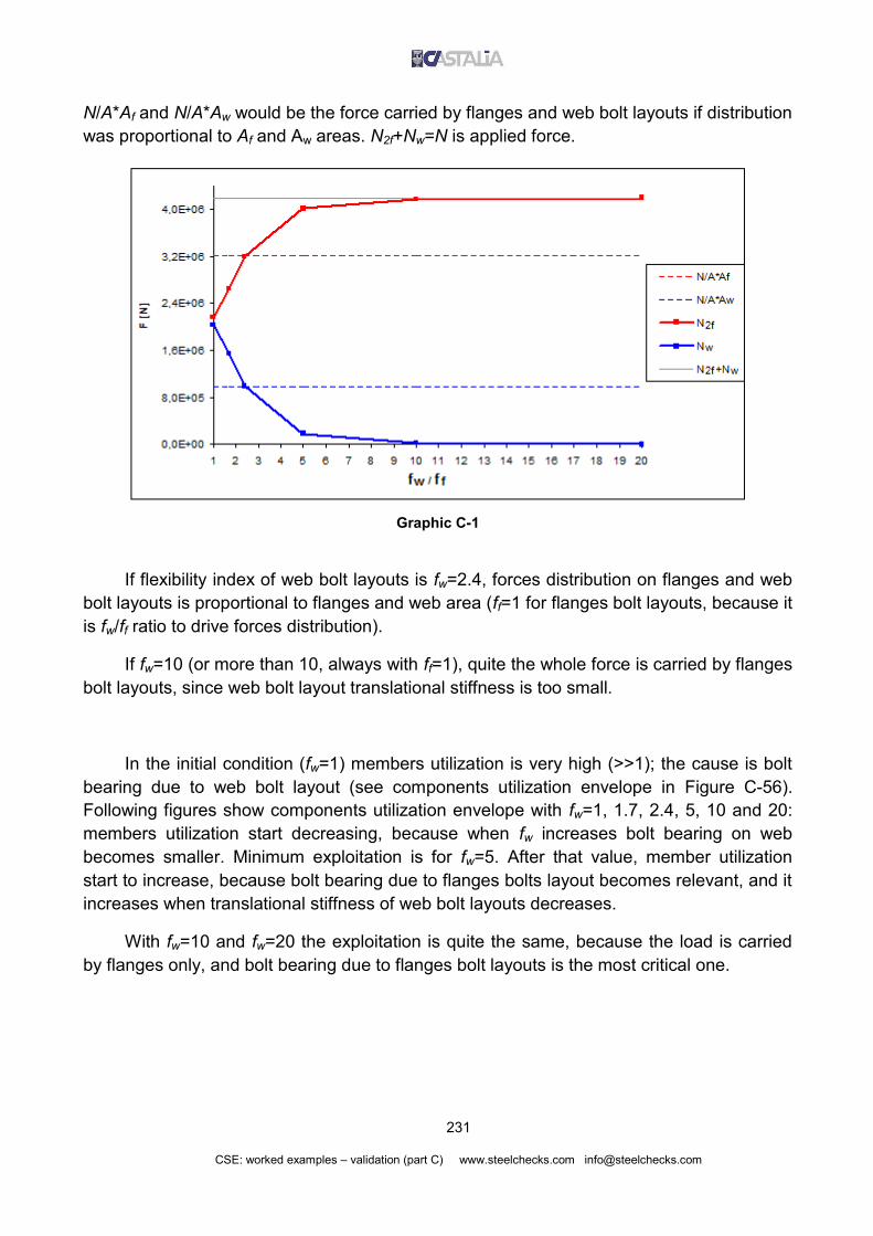
231
CSE: worked examples – validation (part C) www.steelchecks.com [email protected]
N/A*Af and N/A*Aw would be the force carried by flanges and web bolt layouts if distribution
was proportional to Af and Aw areas. N2f+Nw=N is applied force.
Graphic C-1
If flexibility index of web bolt layouts is fw=2.4, forces distribution on flanges and web
bolt layouts is proportional to flanges and web area (ff=1 for flanges bolt layouts, because it
is fw/ff ratio to drive forces distribution).
If fw=10 (or more than 10, always with ff=1), quite the whole force is carried by flanges
bolt layouts, since web bolt layout translational stiffness is too small.
In the initial condition (fw=1) members utilization is very high (>>1); the cause is bolt
bearing due to web bolt layout (see components utilization envelope in Figure C-56).
Following figures show components utilization envelope with fw=1, 1.7, 2.4, 5, 10 and 20:
members utilization start decreasing, because when fw increases bolt bearing on web
becomes smaller. Minimum exploitation is for fw=5. After that value, member utilization
start to increase, because bolt bearing due to flanges bolts layout becomes relevant, and it
increases when translational stiffness of web bolt layouts decreases.
With fw=10 and fw=20 the exploitation is quite the same, because the load is carried
by flanges only, and bolt bearing due to flanges bolt layouts is the most critical one.

232
CSE: worked examples – validation (part C) www.steelchecks.com [email protected]
Figure C-56 Components utilization with fw=1
-------------------------------------------------------------
Members whose maximum exploitation is due to bearing stresses
-------------------------------------------------------------
Inst Combi Name Boltlay Bolt Extr. Sigma Sigma M Expl
1 1 m1 B5 3 2 1.717e+003 4.443e+002 3.865 !!!
1 1 m2 B6 3 2 1.717e+003 4.443e+002 3.865 !!!
B5 is web bolt layout.
Figure C-57 Components utilization with fw=1.7
-------------------------------------------------------------
Members whose maximum exploitation is due to bearing stresses
-------------------------------------------------------------
Inst Combi Name Boltlay Bolt Extr. Sigma Sigma M Expl
1 1 m1 B5 3 2 1.302e+003 4.443e+002 2.929 !!!
1 1 m2 B6 3 2 1.302e+003 4.443e+002 2.929 !!!
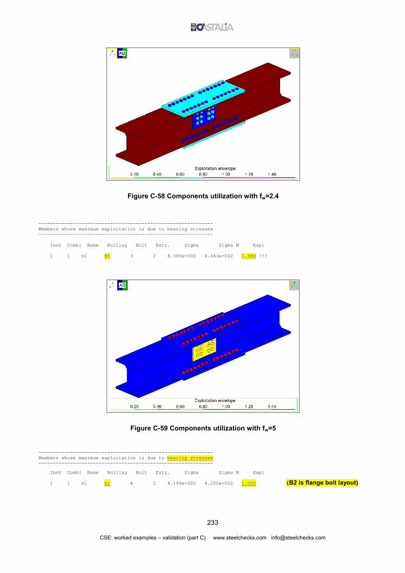
233
CSE: worked examples – validation (part C) www.steelchecks.com [email protected]
Figure C-58 Components utilization with fw=2.4
-------------------------------------------------------------
Members whose maximum exploitation is due to bearing stresses
-------------------------------------------------------------
Inst Combi Name Boltlay Bolt Extr. Sigma Sigma M Expl
1 1 m1 B5 3 2 8.389e+002 4.443e+002 1.888 !!!
Figure C-59 Components utilization with fw=5
-------------------------------------------------------------
Members whose maximum exploitation is due to bearing stresses
-------------------------------------------------------------
Inst Combi Name Boltlay Bolt Extr. Sigma Sigma M Expl
1 1 m1 B2 4 2 4.199e+002 4.200e+002 1.000 (B2 is flange bolt layout)

234
CSE: worked examples – validation (part C) www.steelchecks.com [email protected]
Figure C-60 Components utilization with fw=10
-------------------------------------------------------------
Members whose maximum exploitation is due to bearing stresses
-------------------------------------------------------------
Inst Combi Name Boltlay Bolt Extr. Sigma Sigma M Expl
1 1 m1 B2 4 2 4.364e+002 4.200e+002 1.039 *
Figure C-61 Components utilization with fw=20
-------------------------------------------------------------
Members whose maximum exploitation is due to bearing stresses
-------------------------------------------------------------
Inst Combi Name Boltlay Bolt Extr. Sigma Sigma M Expl
1 1 m1 B2 3 2 4.387e+002 4.200e+002 1.045 *

235
CSE: worked examples – validation (part C) www.steelchecks.com [email protected]
A proper setting of bolt layouts flexibility index can provided the desired condition
among different possible conditions; all these possible conditions guarantee
equilibrium. User can set proper flexibility indexes to model the reduction of stiffness for
some parts of the joint, driving forces to be carried by other parts.
C.8.3 Bending
A copy of the model used in paragraph B.2.1.2 was made (model
Validation_SP_1_1_FlexInd_2.4.CSE). The splice joint is subjected to bending moment,
and its geometry is the same of previous paragraph models. In current model, web bolt
layouts flexibility index is set equal to 2.4, to see how CSE computes forces distribution for
bending moment. The flexibility index assumed is the one providing an applied axial force
distribution proportional to flanges and web area (see previous paragraph).
In the original model (see B.2.1.2) flanges bolt layout carried the 88% of applied load.
A simplified computation of elastic moment distribution between flanges and web would
give a 95.6% (see B.2.1.2). With flexibility index fw=2.4 for web bolt layout, we have the
following load carried by flanges bolt layout:
NmmNh
N 866 10976.42
300106585.12
2106585.12
where 1.6585*106N is the shear carried by flange bolt layout, in CSE computation:
--------------------------------------------------------------------
Forces acting over bolt layouts at different extremes, global system
--------------------------------------------------------------------
Id Inst Combi Ext Fx Fy Fz Mx My Mz
B3 1 1 1 1.0687e-006 -1.6585e+006 2.1023e-006 -1.5176e+007 -8.9636e-006 -2.1371e-004
B3 1 1 2 -1.0687e-006 1.6585e+006 -2.1023e-006 -1.7166e+007 -1.1876e-005 2.1371e-004
B1 1 1 1 1.0687e-006 1.6585e+006 -2.1023e-006 1.5176e+007 -8.9634e-006 -2.1371e-004
B1 1 1 2 -1.0687e-006 -1.6585e+006 2.1023e-006 1.7166e+007 -1.1876e-005 2.1371e-004
B2 1 1 1 -1.0687e-006 1.6585e+006 1.8720e-006 1.5176e+007 8.9634e-006 -2.1371e-004
B2 1 1 2 1.0687e-006 -1.6585e+006 -1.8720e-006 1.7166e+007 1.1876e-005 2.1371e-004
B4 1 1 1 -1.0687e-006 -1.6585e+006 -1.8720e-006 -1.5176e+007 8.9634e-006 -2.1371e-004
B4 1 1 2 1.0687e-006 1.6585e+006 1.8720e-006 -1.7166e+007 1.1876e-005 2.1371e-004
B5 1 1 1 -4.5109e-006 -4.4711e-004 3.5405e-020 -2.5914e-003 2.5937e-005 1.3357e+007
B5 1 1 2 9.0217e-006 9.5804e-004 2.1018e-019 3.8112e-004 9.4483e-016 -2.6713e+007
B5 1 1 3 -4.5109e-006 -5.1093e-004 -2.4559e-019 2.9443e-003 -2.5937e-005 1.3357e+007
B6 1 1 1 -4.5109e-006 5.1315e-004 -2.4524e-019 2.9443e-003 2.5937e-005 1.3357e+007
B6 1 1 2 9.0217e-006 -9.6743e-004 2.0985e-019 3.2401e-004 9.3996e-016 -2.6713e+007
B6 1 1 3 -4.5109e-006 4.5429e-004 3.5387e-020 -2.5914e-003 -2.5937e-005 1.3357e+007
This distribution assigns to flanges bolt layouts the 94.4% of applied load; this
distribution is close to the 95.6% computed considering distribution in cross section
according to an elastic range (which is one of the possible ways to compute distribution).

236
CSE: worked examples – validation (part C) www.steelchecks.com [email protected]
Note well: in hand computations, there is not a single method to evaluate forces
distribution in different bolt layouts. Flexibility index provides in CSE the possibility to drive
forces distribution in order to get desired configuration. Assumptions must be coherent with
the model: for example, we cannot assume that flanges bolt layout carrie the 90% of the
load if we have only 2 bolts on the flanges and 20 bolts on the web.
Figure C-62 Components utilization factor
C.9 BLOCK TEAR CHECKS
Now we are going to study block tear on supported beam in a single sided beam to
beam joint (model Validation_BlockTear_1.CSE). Supported beam cross-section is
IPE200, material is S235. Supported beam is double notched. Tension in supported
member 133856N (see Figure C-65). There is no other applied force.

237
CSE: worked examples – validation (part C) www.steelchecks.com [email protected]
Figure C-63 3D view of the model
Figure C-64 Double notched supported beam

238
CSE: worked examples – validation (part C) www.steelchecks.com [email protected]
Figure C-65 Force exchanged between bolt layout and supported member
Tension in supported beam is equally distributed on the 3 bolts of the layout.
Figure C-66 Forces transferred by single bolts
Possible failure paths for block tearing are shown in Figure C-68; in addition to paths
2, 4 and 5 there are corresponding symmetrical paths, but it is not needed to compute
twice the same conditions.
We will compute the design resistance of each path (Veff,1,Rd) and we will compare it
to applied force (Fa), finding the failure path with the higher Fa/Veff,1,Rd ratio. Design block
tearing resistance according to EN1993-1-8:2005 is:
02,1, /3/1/ MnvyMntuRdeff AfAfV
Failure path 1 is subjected only normal stresses, since the path is exactly normal to
applied force; all the other paths are subjected to both normal stresses and shear stresses,
since paths have parts normal to applied force and parts parallel to applied force. Limit
stresses on these surfaces are, according to the previous formula:
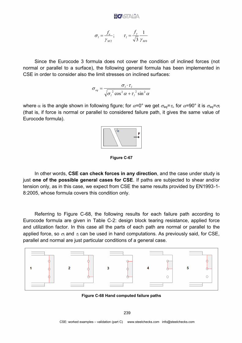
239
CSE: worked examples – validation (part C) www.steelchecks.com [email protected]
02
1
3 ;
M
y
l
M
ul
ff
Since the Eurocode 3 formula does not cover the condition of inclined forces (not
normal or parallel to a surface), the following general formula has been implemented in
CSE in order to consider also the limit stresses on inclined surfaces:
2222sincos ll
lleq
where is the angle shown in following figure; for =0° we get eq=l, for =90° it is eq=l
(that is, if force is normal or parallel to considered failure path, it gives the same value of
Eurocode formula).
Figure C-67
In other words, CSE can check forces in any direction, and the case under study is
just one of the possible general cases for CSE. If paths are subjected to shear and/or
tension only, as in this case, we expect from CSE the same results provided by EN1993-1-
8:2005, whose formula covers this condition only.
Referring to Figure C-68, the following results for each failure path according to
Eurocode formula are given in Table C-2: design block tearing resistance, applied force
and utilization factor. In this case all the parts of each path are normal or parallel to the
applied force, so l and l can be used in hand computations. As previously said, for CSE,
parallel and normal are just particular conditions of a general case.
Figure C-68 Hand computed failure paths

240
CSE: worked examples – validation (part C) www.steelchecks.com [email protected]
path Lv
[mm]
Anv
[mm2]
l
[N/mm2]
Lt
[mm]
Ant
[mm2]
l
[N/mm2]
Veff,1,Rd
[N]
Fa
[N] Rdeff
a
V
F
,1,
1 / / / 120 672.0 288 193536 133856 0.692
2 23.8 133.3 135.7 92 515.2 288 166464 133856 0.804
3 47.6 266.6 135.7 64 358.4 288 139391 133856 0.960
4 47.6 266.6 135.7 32 179.2 288 87782 89237 1.017
5 23.8 133.3 135.7 60 336.0 288 114854 89237 0.777
Table C-2 Results of hand computations on considered failure paths
LV is the length of the part of failure path subjected to shear (considering bolt holes).
Anv∙= Lv∙t is the net area subjected to shear.
t = 5.6mm is supported beam web thickness (IPE 200).
Lt is the length of the part of failure path subjected to axial force.
Ant∙= Lt∙t is the net area subjected to tension.
Veff,1,Rd = Ant∙l + Anv∙l is the design block tearing resistance of considered failure path.
Fa is the resultant force of involved bolts only Fa=F/3*nb.
nb is the number of bolts involved in the considered path.
Most critical path is number 4. It is subjected to the force of 2 bolts only, but it is also
the one with minimum ultimate force, resulting the one with the highest Fa / Veff,1,Rd ratio.
Most critical failure path is shown in Figure C-69: a part of supported beam web is
torn from the rest of the member. Resultant on involved bolts is 2/3 of total applied load.
Figure C-69 Failure path number 4

241
CSE: worked examples – validation (part C) www.steelchecks.com [email protected]
Step-by-step computation of Fa/Veff,1,Rd for most critical failure path is shown now
(only the results were printed in Table C-2). Reader could easily hand compute the other
paths, if desired. First of all, we compute limit stresses value for S235 with M0=1 and
M2=1.25.
22
2
/28825.1
/360mmN
mmNf
M
ul
22
0
/7.1351
1
3
/2351
3mmN
mmNf
M
y
l
According to following figure, we can compute the length of each part of the path.
Figure C-70 Relevant distances [mm]
We get5
mmmm
mmLt 322
13245
mmmm
mmLv 6.472
133.302
22.1796.532 mmmmmmtLA tnt
26.2666.56.47 mmmmmmtLA vnv
NmmNmmmmNmmAAV lnvlntRdeff 87782/7.1356.266/2882.179 2222
,1,
Resultant on failure path 4 is due to 2 bolts only:
NNFFa 892371338563
2
3
2
5 hole diameter d0=13mm for M12 bolts

242
CSE: worked examples – validation (part C) www.steelchecks.com [email protected]
Utilization factor of failure path 4 is:
017.187782
89237expl
,1,
N
N
V
F
Rdeff
a
The following figure shows the results computed by CSE. Most critical failure path is
the same computed as most critical in our hand computations (see figure). Utilization factor
is 1.0159, very close to the one hand computed (-0.1%). The difference is due to a slight
difference in Fultimate (design block tear resistance) computation. Applied force is exactly 2/3
of total applied force.
Figure C-71 CSE results for block tear check
--------------------------------------------------------------------
Members whose relevant exploitation is due to block tear checks
--------------------------------------------------------------------
Inst Combi Name Blayout Angle Force U Force A Expl
1 25 m2 B1 -0.000 8.784e+004 8.924e+004 1.016 *

243
CSE: worked examples – validation (appendix) www.steelchecks.com [email protected]
D. APPENDIX: ABSTRACTS FROM EN 1993-1-1: 2005
Figure D-1 Abstract from EN1993-1-8: bolts fyb and fub

244
CSE: worked examples – validation (appendix) www.steelchecks.com [email protected]
Figure D-2 Abstract from EN1993-1-8: Bolts spacing, end and edge distances
Spacing and distances according to next figure.

245
CSE: worked examples – validation (appendix) www.steelchecks.com [email protected]
Figure D-3 Abstract from EN1993-1-8: Bolts spacing, end and edge distances

246
CSE: worked examples – validation (appendix) www.steelchecks.com [email protected]
Figure D-4 Abstract from EN1993-1-8: Design resistance for individual fasteners

247
CSE: worked examples – validation (appendix) www.steelchecks.com [email protected]
Figure D-5 Abstract from EN1993-1-8: Correlation factor w for fillet welds
