workflow for control system design and implementation - · pdf filepower management...
TRANSCRIPT
1 © 2012 The MathWorks, Inc.
Workflow for Control System Design
and Implementation
- Dhirendra Singh, Application Engineer
- Shobhit Shanker, Application Engineer

2
Agenda
Industry Trends and Challenges
Design PID Controller & Feedback Compensator
Adding Control logic
Implementing control algorithm

3
Challenge- Increasing Software Content
Power
Management
Transmission
Control
Engine
Control
Ride Control
ABS
Steering
Stability
Controls
Traction Control
Obstacle
Detection
Adaptive Cruise
Control
Crash
Avoidance
Airbags
Adaptive Front
Lighting Systems
Passenger
Detection
Windows
Doors
Lights Climate Controls
Driver Drowsiness
Infotainment Instrumentation
Voice
Recognition
Navigation
Wireless
Connectivity
Tire Pressure
Monitoring
Software content increasing 3x – 5x per year
How to develop and manage such large
amount of software?

4
Hybrids x-EV’s Driver-less
1980 1990 2000 2010 2020 1970
Ignition Fuel
Injection
ABS
ETC
ESC ACC
GDI
PCS
BCM HVAC AFS
DCT HCCI
LDWS
HUD Abstraction
Motorola 6800
8 bit/ 1 MHz / 4 kBytes
Microcode/Assembly
C
Modeling
Freescale MPC5674F
32 bit / 200+ MHz / 4000 kBytes Processor
Growth of Automotive Electronics and Software
5
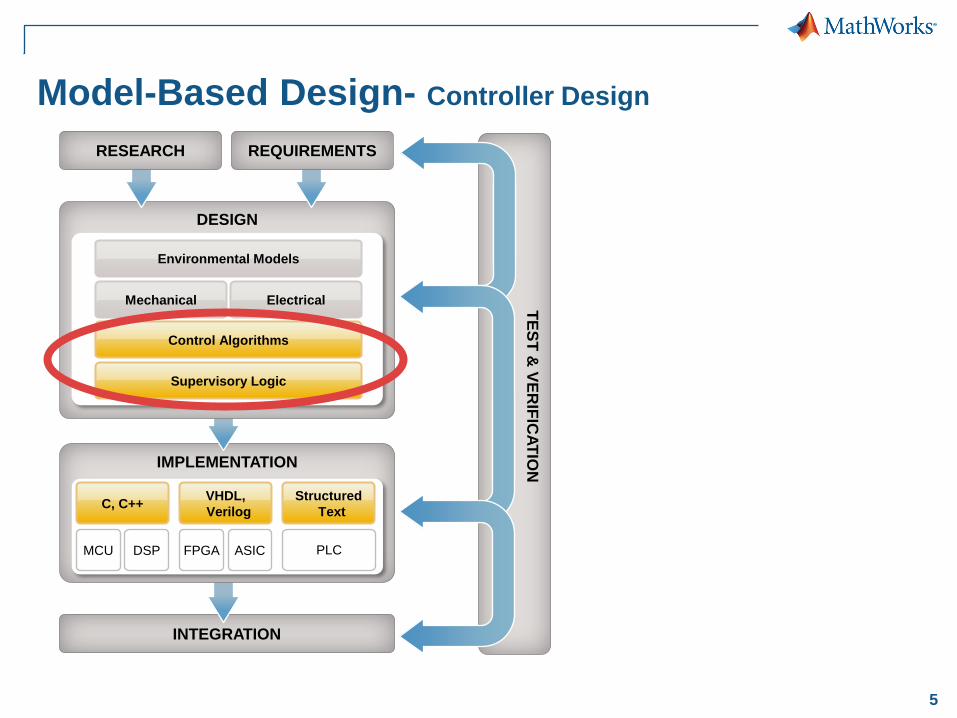
INTEGRATION
IMPLEMENTATION
TE
ST
& V
ER
IFIC
AT
ION
Model-Based Design- Controller Design
DESIGN
Environmental Models
Control Algorithms
Mechanical Electrical
Supervisory Logic
RESEARCH REQUIREMENTS
MCU DSP FPGA ASIC
Structured
Text
VHDL,
Verilog C, C++
PLC

6
What is Our End Goal?
Real-Time or
Embedded
Embedded Processor or ECU
Code
Generation
7
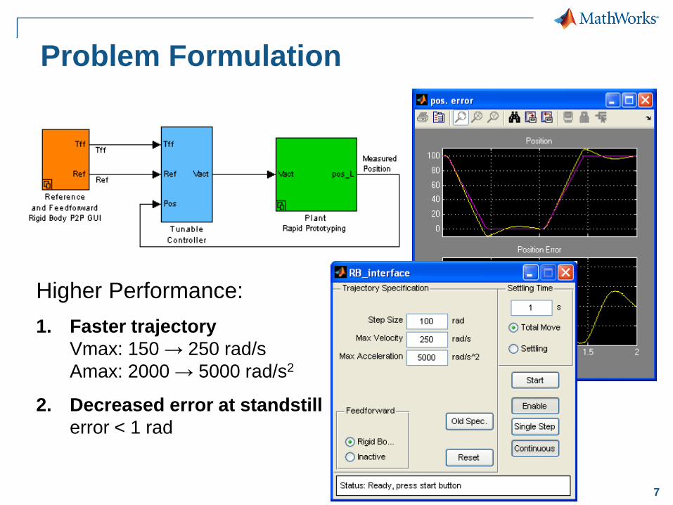
Problem Formulation
Higher Performance:
1. Faster trajectory
Vmax: 150 → 250 rad/s
Amax: 2000 → 5000 rad/s2
2. Decreased error at standstill
error < 1 rad

8
Agenda
Industry Trends and Challenges
Design PID Controller & Feedback Compensator
Adding Control logic
Implementing control algorithm
9
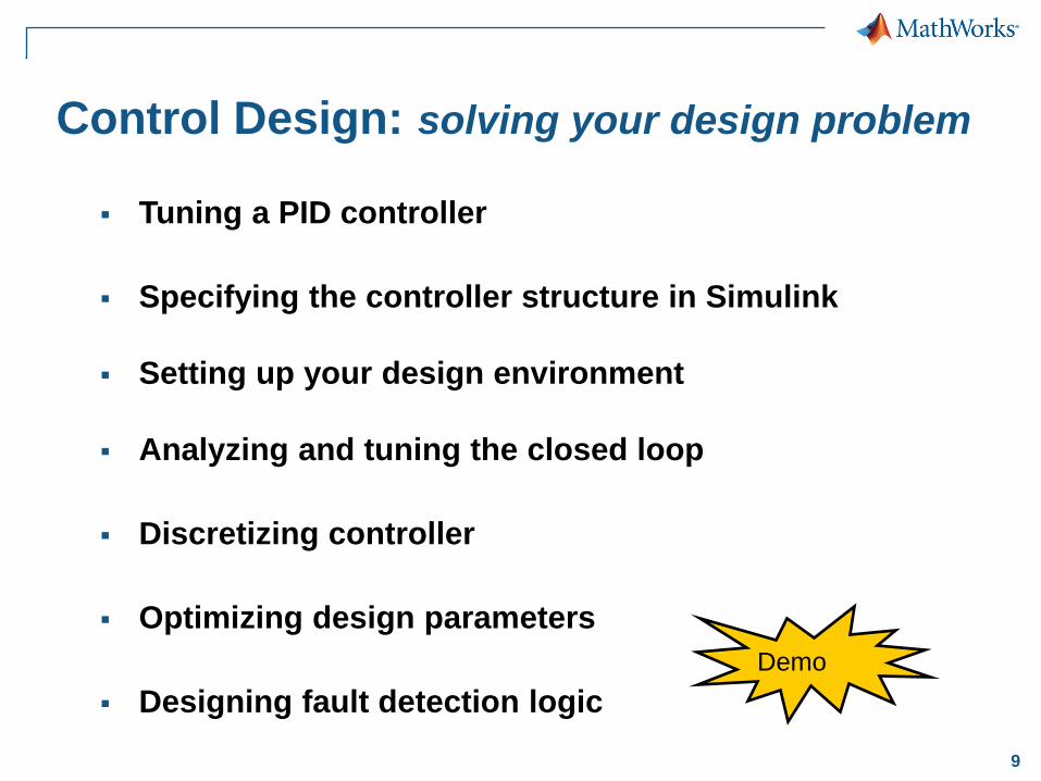
Control Design: solving your design problem
Tuning a PID controller
Specifying the controller structure in Simulink
Setting up your design environment
Analyzing and tuning the closed loop
Discretizing controller
Optimizing design parameters
Designing fault detection logic
Demo

10
PID Controller Block with Automatic Tuning
11
Agenda
Design PID Controller & Feedback Compensator
Adding Control logic
Implementing control algorithm
12
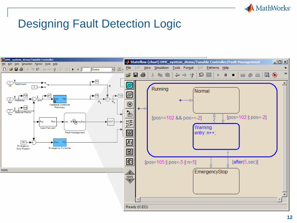
Designing Fault Detection Logic

13
INTEGRATION
IMPLEMENTATION
TE
ST
& V
ER
IFIC
AT
ION
Model-Based Design- Implementation
DESIGN
Environmental Models
Control Algorithms
Mechanical Electrical
Supervisory Logic
RESEARCH REQUIREMENTS
MCU DSP FPGA ASIC
Structured
Text
VHDL,
Verilog C, C++
PLC
14
Agenda
Design PID Controller & Feedback Compensator
Adding Control logic
Implementing control algorithm

15 © 2012 The MathWorks, Inc.
Workflow for Control System Design -
Implementation
Shobhit Shanker
Senior Application Engineer- Code Generation and Verification

16
Implement Model as Software On-target
Real-Time or
Embedded
Embedded Processor or ECU
Code
Generation
17
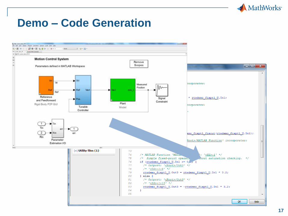
Demo – Code Generation

18
How Did We Get Here?

19
Workflow For Embedded Code Generation
Setting up-Code Generation Environment
– Modeling Guidelines Checking
– Code Generation Advisor Settings e.g. RAM/ROM
Add Software Design Details – Algorithm Partitioning e.g. reusable libraries, Model reference
– Data Typing , Scoping of Variables, Fixed Point Details, Sw-DD
Generate Code & Review – Peer review, Code Walkthrough
– Standards Compliance e.g. MISRA-AC-AGC
Verification and Integration of Code – Software-in-loop testing(SIL)
– Processor-in-Loop(PIL) for Target Testing
– Platform Integration

20
Setting up Code-Generation Environment
Discretizing the model
– Variable Fixed-Step
Code Advisor
Float-Fixed point
conversion
Modeling guidelines
checking MAAB,
DO178B/C, ISO26262
V
21
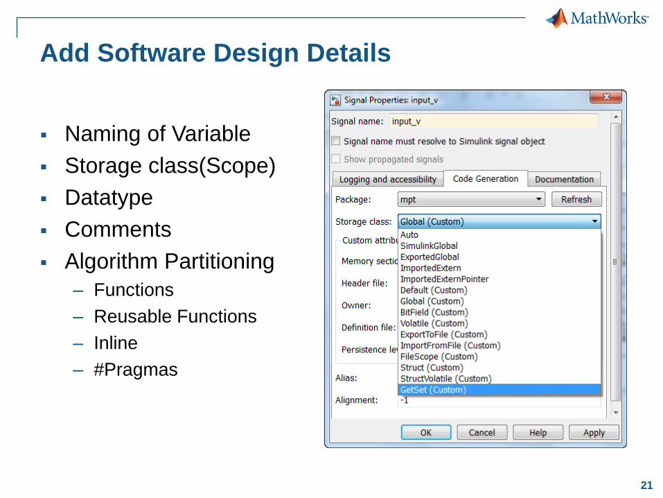
Add Software Design Details
Naming of Variable
Storage class(Scope)
Datatype
Comments
Algorithm Partitioning
– Functions
– Reusable Functions
– Inline
– #Pragmas

22
Generate Code and Review
Traceability
Static Code Metrics
– RAM
– Call Tree
– SLOC
Comments
23 © 2012 The MathWorks, Inc.
Continuous Test and
Verification (SIL/PIL)
Executable
Specifications
Design
with
Simulation
Automatic
Code Generation
Continuous
Test and
Verification Models
24
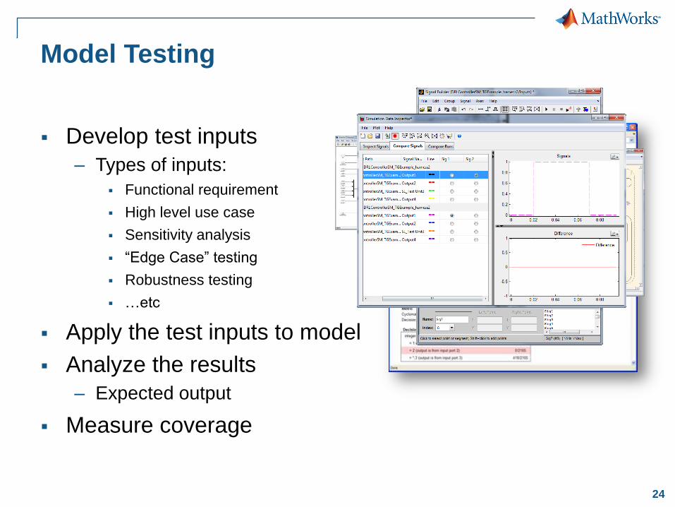
Model Testing
Develop test inputs
– Types of inputs:
Functional requirement
High level use case
Sensitivity analysis
“Edge Case” testing
Robustness testing
…etc
Apply the test inputs to model
Analyze the results
– Expected output
Measure coverage
25
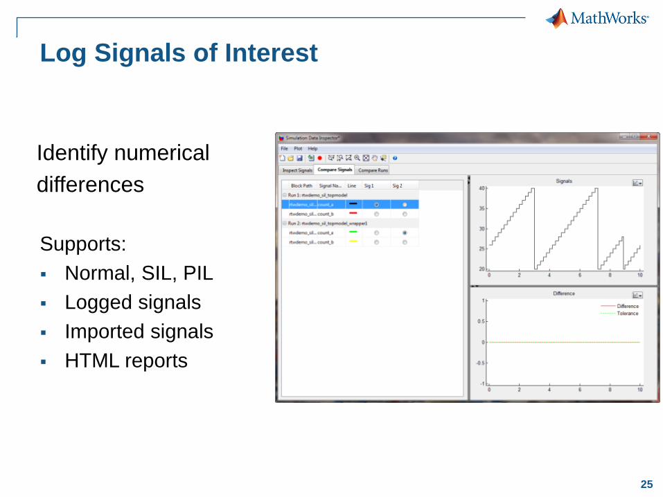
Log Signals of Interest
Supports:
Normal, SIL, PIL
Logged signals
Imported signals
HTML reports
Identify numerical
differences

26
Software-in-the-Loop (SIL) Testing: Verify Production Controller with Software-in-the-loop
Compiled C Code
S-Function (Windows DLL)
Code
Generation
Execution
• Host/Host
• Nonreal-time
27
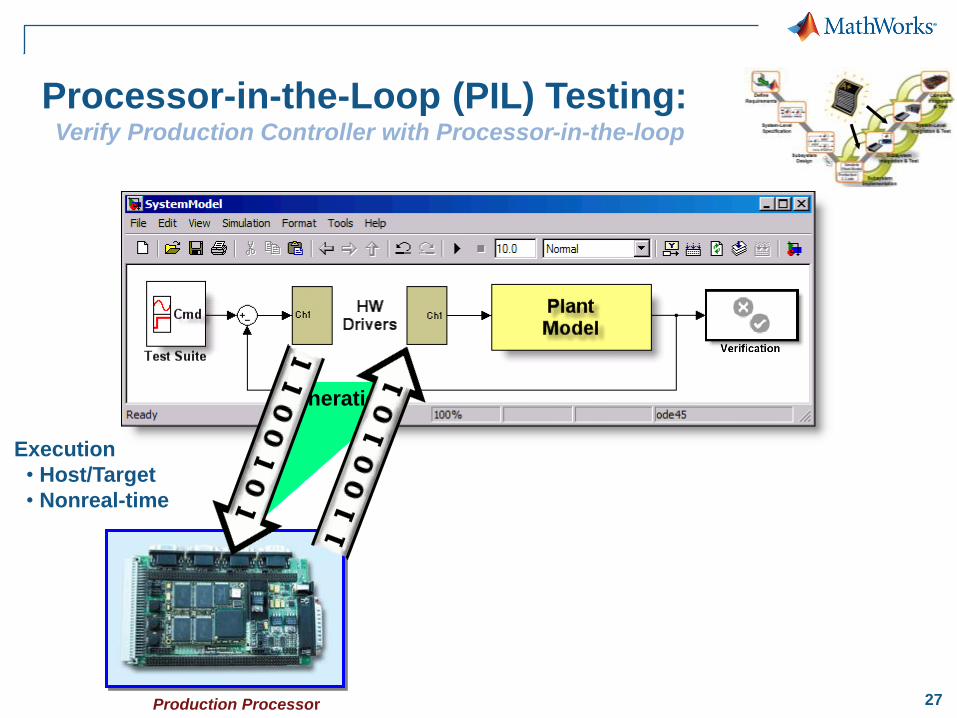
Processor-in-the-Loop (PIL) Testing: Verify Production Controller with Processor-in-the-loop
Production Processor
Code
Generation
Execution
• Host/Target
• Nonreal-time
28
A B C
M
I N P U T
B L U E G R E E N R E D
P O W E R
RGBSplit-4BLACK BOX
V R C S
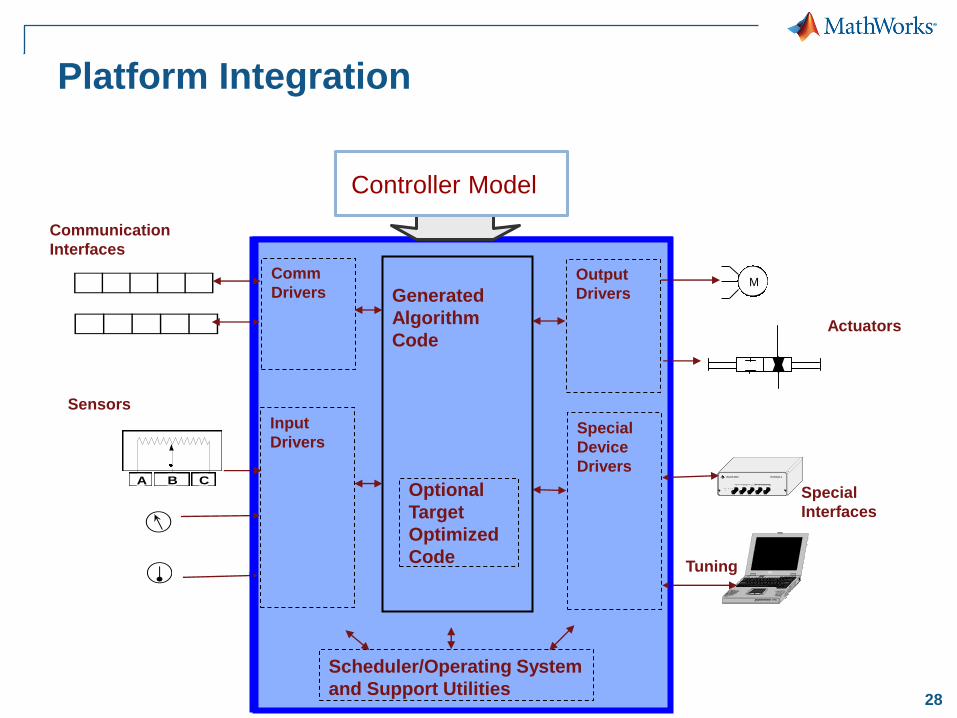
Generated
Algorithm
Code
Input
Drivers
Output
Drivers
Special
Device
Drivers
Comm
Drivers
Scheduler/Operating System
and Support Utilities
Communication
Interfaces
Sensors
Actuators
Special
Interfaces
Tuning
Optional
Target
Optimized
Code
Controller Model
Platform Integration
29
Summary
Design, Tune and Test Controllers in Simulink
Convert Controller Models to Embedded Code
Test Generated Code on Target
30
What’s Next?
Explore >>rtwdemos
Attend Embedded Code Generation class www.mathworks.com/services/training/courses/SLEC_1.html
Request Advisory Services: Developing Embedded
Targets, Model-Based Design for ISO 26262 or DO-178
www.mathworks.com/services/consulting/areas/design.html
Read Technical Articles and User Examples
www.mathworks.com/programs/techkits/pcg_tech_kits.html
Thank You!