working group 2 – introductory presentation
TRANSCRIPT

Working Group 2 –Introductory presentation.
Convenors –C. Adolphsen, T. Garvey, H. Hayano

Topics covered by WG2
• Modulators / klystrons• RF wave-guide distribution• Low Level RF• Beam interfaces (quadrupoles, BPM’s)• Cryomodule• Cryo-systems
Important interfaces with other WG’s especially WG5

Outline of presentation
• Progress in WG2 topics since last ILC meeting(will not necessarily be exhaustive!).– Not new R&D results; rather, “firming up” of plans for
future R&D, re-orientation of Americas and Asian accelerator activities towards L-band / SC RF.
– CARE / SRF activities in Europe– TTF-linac / X-FEL activities
• Overview of WG2 sessions to be held here.• What WG2 hope to accomplish at this meeting.

FNAL-Based SMTF Proposal: “It is anticipated that, with coordination from the ILC-Americas collaboration, SLAC will lead the ILC rf power source efforts ...
Focus of Efforts at JLab and FNAL
Focus of Efforts at SLAC

SLAC plans for ILC RF Sources• Initial SLAC program will focus on:
– Establishing a 1.3 GHz test stand to gain experience with L-bandtechnology. Will test NC structures and cavity power couplers.
– Developing alternatives to the baseline modulator and klystron to reduce cost and improve efficiency and reliability.
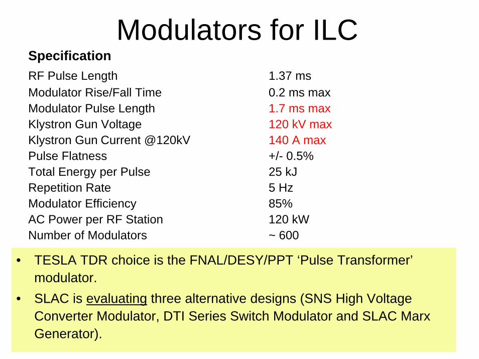
SpecificationRF Pulse Length 1.37 msModulator Rise/Fall Time 0.2 ms maxModulator Pulse Length 1.7 ms maxKlystron Gun Voltage 120 kV maxKlystron Gun Current @120kV 140 A maxPulse Flatness +/- 0.5%Total Energy per Pulse 25 kJRepetition Rate 5 HzModulator Efficiency 85%AC Power per RF Station 120 kWNumber of Modulators ~ 600
• TESLA TDR choice is the FNAL/DESY/PPT ‘Pulse Transformer’modulator.
• SLAC is evaluating three alternative designs (SNS High Voltage Converter Modulator, DTI Series Switch Modulator and SLAC Marx Generator).
Modulators for ILC
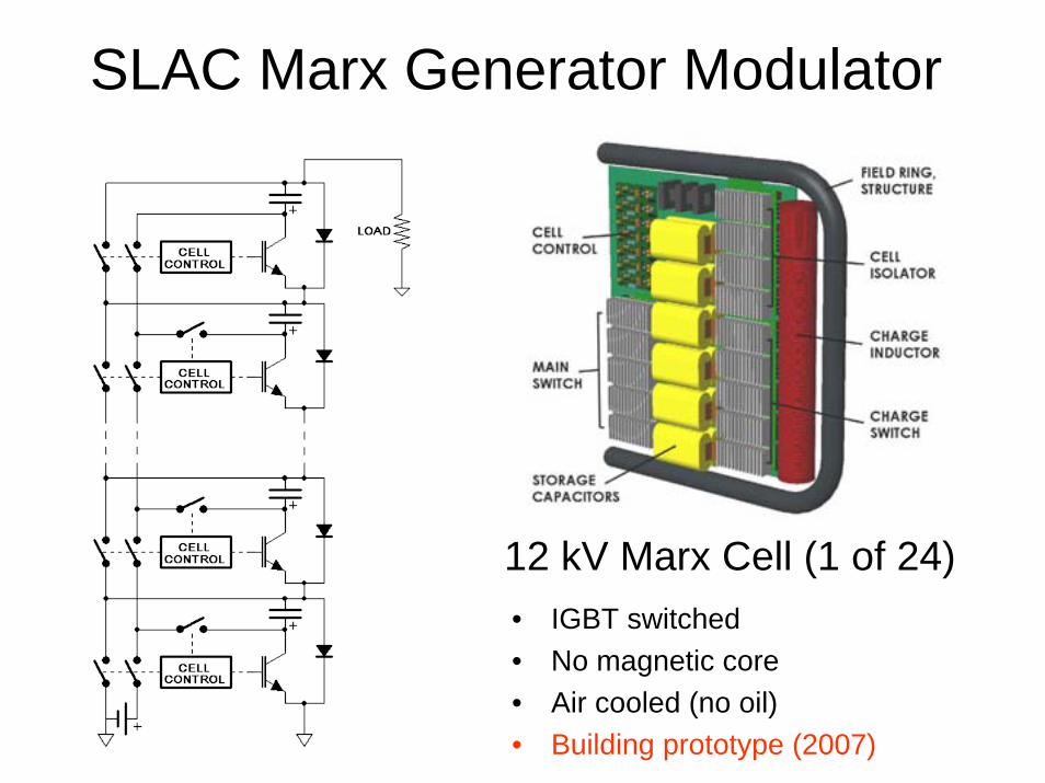
SLAC Marx Generator Modulator
12 kV Marx Cell (1 of 24)• IGBT switched• No magnetic core• Air cooled (no oil)• Building prototype (2007)
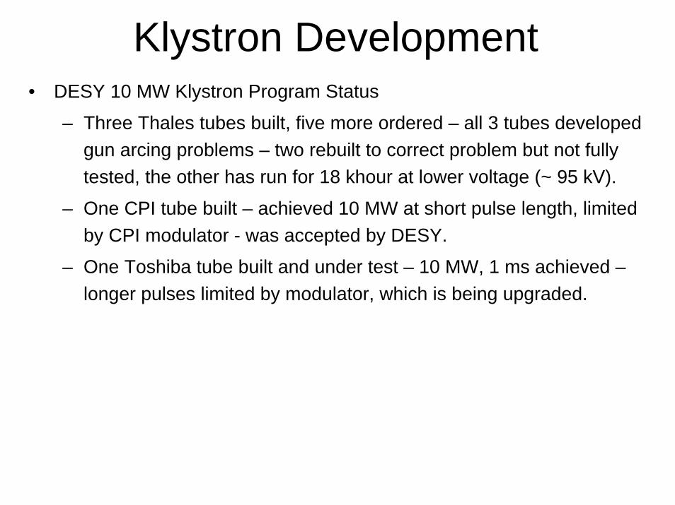
Klystron Development• DESY 10 MW Klystron Program Status
– Three Thales tubes built, five more ordered – all 3 tubes developed gun arcing problems – two rebuilt to correct problem but not fully tested, the other has run for 18 khour at lower voltage (~ 95 kV).
– One CPI tube built – achieved 10 MW at short pulse length, limited by CPI modulator - was accepted by DESY.
– One Toshiba tube built and under test – 10 MW, 1 ms achieved –longer pulses limited by modulator, which is being upgraded.

ILC KlystronDevelopment
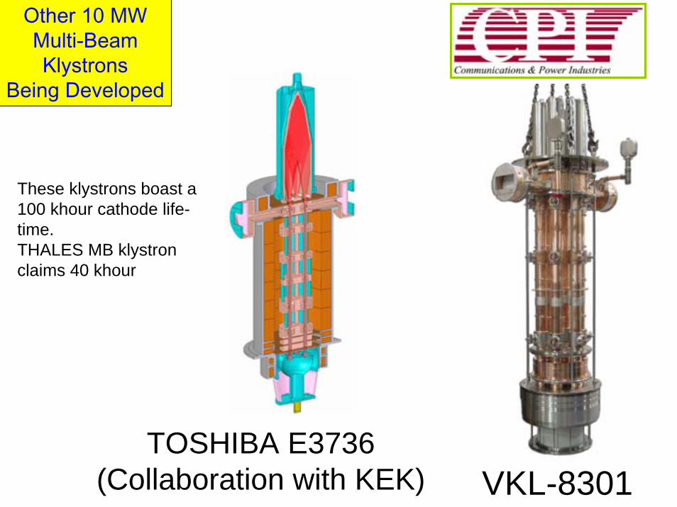
VKL-8301TOSHIBA E3736
(Collaboration with KEK)
Other 10 MWMulti-BeamKlystrons
Being Developed
These klystrons boast a 100 khour cathode life-time.THALES MB klystron claims 40 khour

SLAC Klystron program
– Developing a 10 MW L-band Sheet-Beam Klystron.
– If multi-beam program falters, consider lower perveance, single beam, 5 MW tube, possibly with PPM focusing.
– Buy commercial 5 MW tubes as needed for 1.3 GHz NC structure and coupler program.
– Possibly collaborate with DESY and CPI on 10 MW tube.
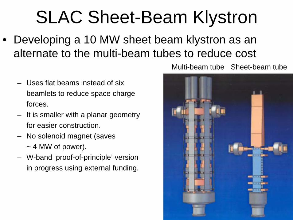
SLAC Sheet-Beam Klystron• Developing a 10 MW sheet beam klystron as an
alternate to the multi-beam tubes to reduce cost
– Uses flat beams instead of sixbeamlets to reduce space chargeforces.
– It is smaller with a planar geometryfor easier construction.
– No solenoid magnet (saves ~ 4 MW of power).
– W-band ‘proof-of-principle’ versionin progress using external funding.
Sheet-beam tubeMulti-beam tube

Gun
Wiggler TypeFocusing Using
Permanent Magnets
OutputCavity
Collector
10 MW L-BandSheet-Beam
Klystron

L-Band Test Facility at NLCTA• Recently acquired a 10 MW HVCM Modulator from SNS.• Buying a 5 MW TH2104C tube from Thales (1 year delivery).
– In meantime use a SDI-Legacy tube from Titan (TH2104U).• All major LLRF and waveguide components on order.
SNS Modulator Being Assembled at NLCTA Thales 2104U Klystron

SLAC Test Facility Program in 2006 (C. Adolphsen)
• Use 5 MW source for coupler and normal-conducting cavity tests • Propose to add a second L-band station using ILC prototypes.
– Depending on progress, use Marx Generator, DTI Direct Switch or buy a “baseline” modulator from PPT.
– Buy (or borrow) a CPI or Toshiba 10 MW klystron.

SLAC ILC Linac SC Quad/BPM Evaluation• Goal: Demonstrate Quad/BPM performance required for ILC beam-based alignment:
– Verify < ~ 5 micron movement of Quad magnetic center with field change.
– Show ~ 1 micron BPM resolution and < ~ 5 micron Quad-to-BPM stability with a compact RF cavity BPM.
• For this program we plan to
– Develop linac rRF cavity BPMs and test them with beam.
– Acquire the ILC prototype Quad built by CIEMAT (Spain) and build a test cryostat for it at SLAC.
– Do quad center stability tests with a rotating coil at the SLAC Magnetic Measurements Lab.
• Status
– Quad nearly finished and cryostat and coil engineering underway – expect first magnet test in 2/06.
– BPM design complete – test with beam in 2006.
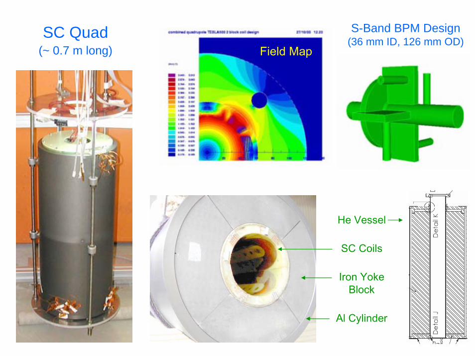
SC Quad(~ 0.7 m long)
S-Band BPM Design(36 mm ID, 126 mm OD)
Field Map
Al Cylinder
Iron YokeBlock
SC Coils
He Vessel

SLAC WG2 Activity Summary• Programs started in FY05
– Assemble an L-band RF station at NLCTA
– Build IGBT switching circuits for two SMTF modulators
– Develop a Marx-generator style modulator
– Develop an L-band sheet-beam klystron
– Demonstrate linac quad and bpm performance for ILC beam-based alignment.
• Programs proposed for FY06
– Build a second L-band station with ILC prototype modulator and klystron (collaborate with DESY).

Plans at KEK for an L-band Test Facility
Operate high gradient modules with beam

STF Phase 1 RF Wave-guide Distribution
Power distribution scheme

0
1
2
3
4
5
6
0 100 200 300 400 500Pin(W)
Pout
(MW
)
1300MHz1296MHz
STF Modulator, klystron plan & status1. Reuse an old TH2104A klystron, driven by an existing PNC modulator by
adding a bouncer circuit and a new pulse transformer. Initial operation is scheduled in Dec. 2005 for testing the cavity input couplers. Relocate this system later for running an RF-gun.
Additional Pulse Trans +Bouncer circuit allows to use TH2104A.
Existing PNC modulator
TH2104A old klystron short pulse test. Design of Pulse Trans is underway.
5MW, 2µs RF was confirmed.
5MW
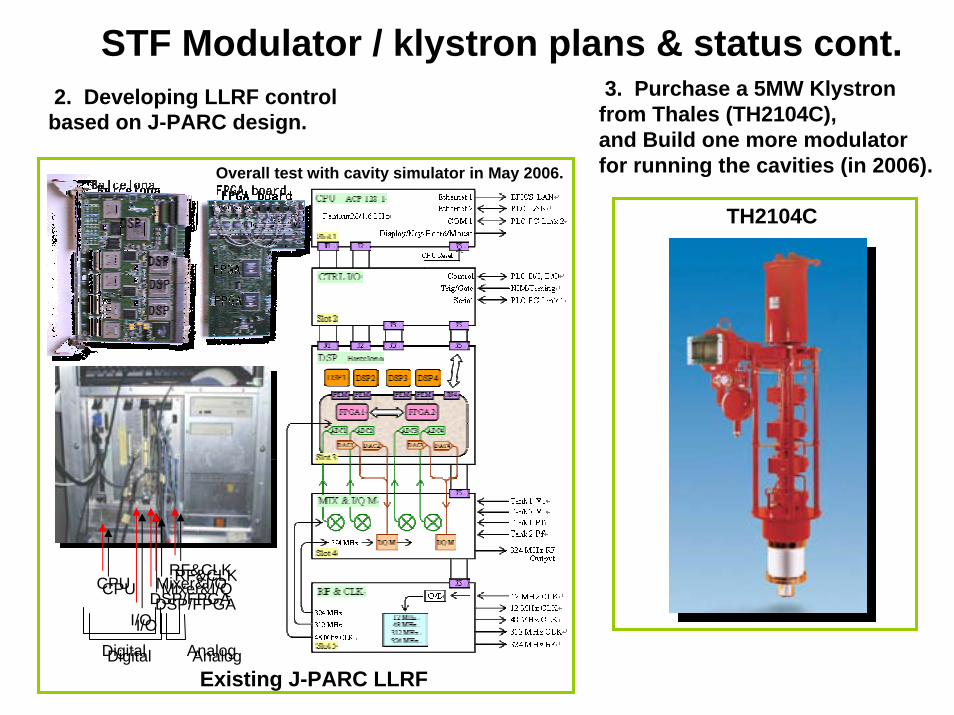
STF Modulator / klystron plans & status cont.
TH2104C
2. Developing LLRF control based on J-PARC design.
3. Purchase a 5MW Klystron from Thales (TH2104C), and Build one more modulatorfor running the cavities (in 2006).
CPUCPU
I/OI/ODSP/FPGADSP/FPGAMixer&I/QMixer&I/QRF&CLKRF&CLK
Digital AnalogDigital Analog
Overall test with cavity simulator in May 2006.
Existing J-PARC LLRF

STF Phase 2 : Build ILC Main Linac RF unit

Low Level RF Development Design of Eight Channel 81 MHz IF Down-converter Board in Digital RF Feedback System for TTF2 -
Modular & Reconfigurable Common PCB-Platform of FPGA Based LLRF Control System for TESLA Test Facility
DSP Integrated Parameterized FPGA Based Cavity Simulator & Controller
FPGA Based, Full-Duplex, Multi-Channel, Multi-Gigabit, Optical, Synchronous Data Transceiver for TESLA Technology LLRF Control System
First Generation of Optical Fiber Phase Reference Distribution System for TESLA
DOOCS Environment for FPGA Based Cavity Control System and Control Algorithms Development
FPGA and Optical Network Based LLRF Distributed Control System for TESLA-XFEL Linear Accelerator
Prototype Implementation of the Embedded PC Based Control and DAQ Module for TESLA Cavity SIMCON
Digital control systems being developed by S. Simrock and collaborators from Warsaw.
Work performed within SRF JRA of CARE (WP8).
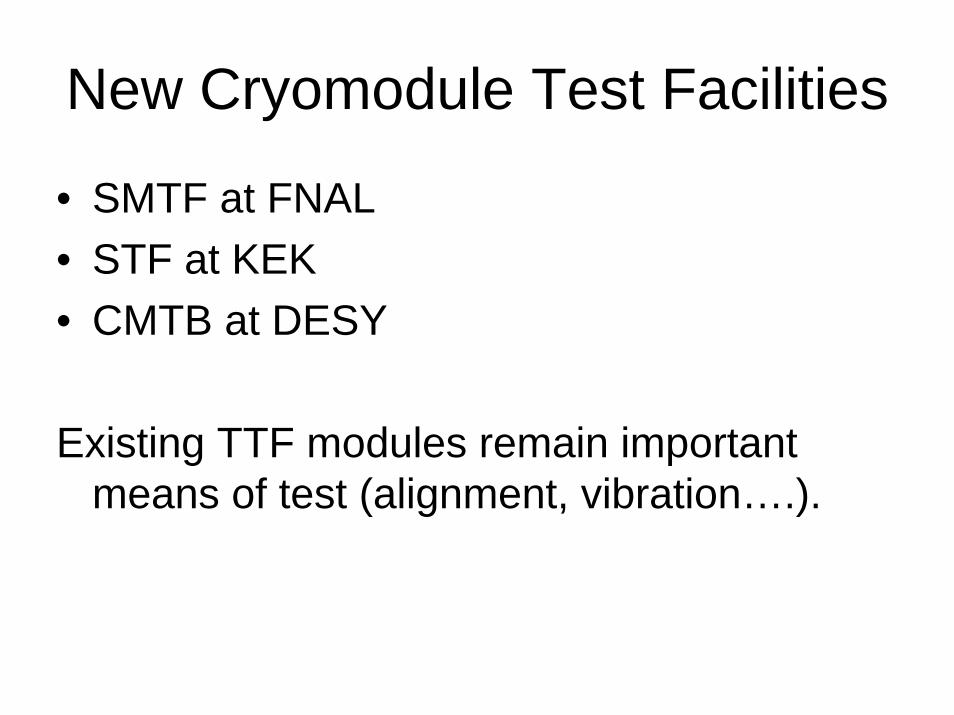
New Cryomodule Test Facilities
• SMTF at FNAL• STF at KEK• CMTB at DESY
Existing TTF modules remain important means of test (alignment, vibration….).

Main Goal: Develop U.S. Capabilities in fabricating and operating with BeamSuperconducting accelerating cavities and cryomodule in support of the
International Linear Collider.
High gradient (35 MV/m or Greater) and high Q (~0.5-1e10)
1.3 GHz ILC Cryomodule
4 Cavities US Built/purchased
4 Cavities KEK Built/US processed
Shekhar Mishra
Superconducting Module Test Facility (SMTF) at FNAL
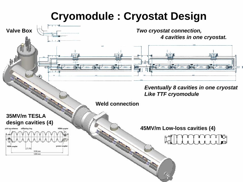
Cryomodule : Cryostat Design
35MV/m TESLAdesign cavities (4)
45MV/m Low-loss cavities (4)
Weld connection
Valve Box Two cryostat connection,4 cavities in one cryostat.
Eventually 8 cavities in one cryostatLike TTF cryomodule

XFEL Test Hall Layout

Prototype test programCMTB (DESY)
• In general: cryomodule tests independent from linac operation• RF cavity processing / performance • processing of RF couplers • cryogenic performance• tests of vacuum systems• tests after repairs before installation into linac• tests of new design features ( 2K quad ...etc.)• dark current• stretched wire, WPMs • thermal cycling• operation at different HE II bath temperatures• .........
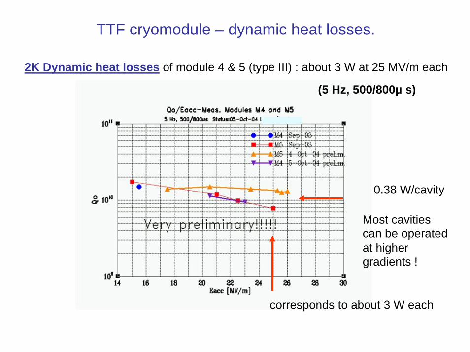
TTF cryomodule – dynamic heat losses.
2K Dynamic heat losses of module 4 & 5 (type III) : about 3 W at 25 MV/m each
corresponds to about 3 W each
0.38 W/cavity
(5 Hz, 500/800µ s)
Most cavitiescan be operatedat highergradients !

Vibration measurements on quad at end of module ACC4 (H. Brueck / DESY)
1 10 100 1 1031 10 4
1 10 3
0.01
0.1Vertical Sensors Module #4
Hz
mu
RMSTi 2
RMSTi 3
RMSTi 6
fi fi fi
Piezo blue and pink, Geophone red
• Good agreement between– the two piezos– piezo and geophone (20%)
• Low RMS: 34 43 45 nm for f>2Hz • Comparable with ground motions measured
by Ehrlichmann• At low frequencies the noise signal is
probably getting dominant
RMS average, Saturday midnight ± 1 hour
210804 2300 220804 0100
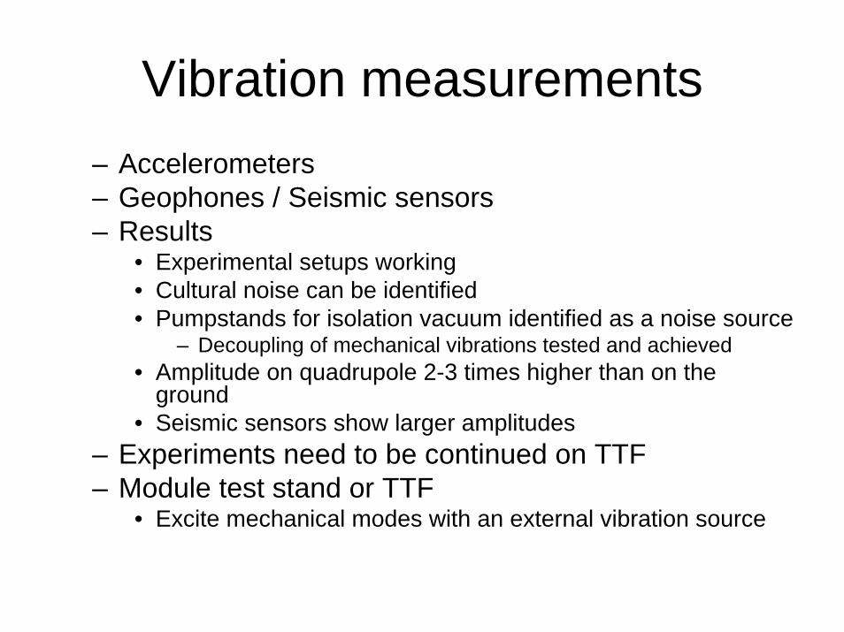
Vibration measurements– Accelerometers– Geophones / Seismic sensors– Results
• Experimental setups working• Cultural noise can be identified• Pumpstands for isolation vacuum identified as a noise source
– Decoupling of mechanical vibrations tested and achieved• Amplitude on quadrupole 2-3 times higher than on the
ground• Seismic sensors show larger amplitudes
– Experiments need to be continued on TTF– Module test stand or TTF
• Excite mechanical modes with an external vibration source

X-FEL Module Industrial StudyDeutsches Elektronen Synchrotron (DESY) to launch a call for tender and for contracting of the Industrial Study on behalf of the TESLA-collaboration, the X-FEL project, the EUROFEL design study and BESSY.
The present cryomodule assembly procedures and some aspects of the present design shall be analyzed and questioned with respect to the most cost effective series production.
The key aspects of the study are as follows:1.2.1 Define the assembly procedure1.2.1 Analyze cost-reduction and production efficiency measures1.2.3 Analyze performance improvement measures1.2.4 Supply a cost estimate for the module production
An important of the IS will be the presence of CONTRACTORs’experts during the assembly of two prototype cryo-modules at DESY.
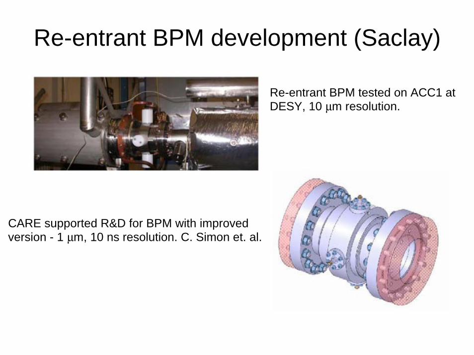
Re-entrant BPM development (Saclay)
CARE supported R&D for BPM with improved version - 1 µm, 10 ns resolution. C. Simon et. al.
Re-entrant BPM tested on ACC1 at DESY, 10 µm resolution.
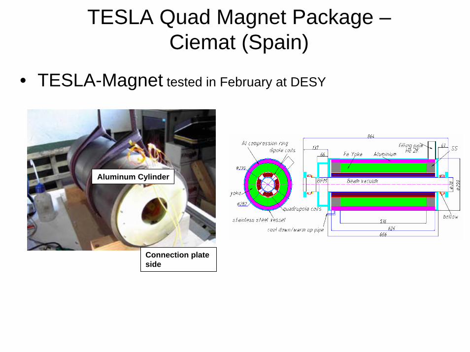
TESLA Quad Magnet Package –Ciemat (Spain)
• TESLA-Magnet tested in February at DESY
Connection plate side
Aluminum Cylinder

Schedule for Linac Design Sessions (WG2)
Tuesday Morning : Modulators and LLRF
Tuesday Afternoon : Klystrons and RF Distribution
Wednesday Morning : Cryomodules with WG5
Wednesday Afternoon : Couplers with WG5
Thursday Morning : Beam Dynamics and Wakefields with WG1
Thursday Afternoon : Baseline Design Options with WG1,5
Talks with Global Groups
Talks During the Second Week

Tuesday Morning, August 16Time Dura
tionTopic Presentation Institution Speaker /
ModeratorJoint with
8:30 30 Modulator overview
Modulator requirements and comparison of the various proposals in terms of functionality, serviceability and cost.
SLAC Ray Larsen
9:00 15 Status of the PPT modulators at DESY and modulator plans for the XFEL
DESY Stefan Choroba
9:15 15 Upgrade of the FNAL modulator for SMTF
FNAL Howie Pfeffer
9:30 30 Coffee Break
10:00 20 Marx modulator developmentprogram
SLAC Greg Leyh
10:20 20 Overview of solid state modulator options and assessments
DTI Jeff Casey
10:40 10 Optimized Converter-Modulator Design Topology for the ILC Application
LANL Bill Reass
10:50 10 Long distance transmission of HV pulses
SLAC Dick Cassel
10:00 10 Phase and amplitude requirements on various length and time scales
SLAC Peter Tenenbaum
10:10 20 Experience at TTF and development for the XFEL and ILC
DESY Stefan Simrock
11:30 20 SNS LLRF design experience and its possible adoption for ILC
FNAL Brian Chase
11:50 10 Summary Discussion of summary slides
LLRF
Alternative modulatordesigns
TDR modulatordesign
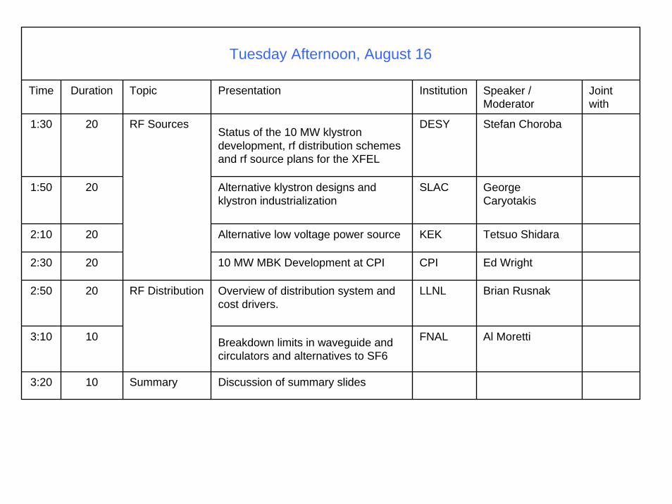
Tuesday Afternoon, August 16
Time Duration Topic Presentation Institution Speaker / Moderator
Joint with
1:30 20Status of the 10 MW klystron development, rf distribution schemes and rf source plans for the XFEL
DESY Stefan Choroba
1:50 20 Alternative klystron designs and klystron industrialization
SLAC George Caryotakis
2:10 20 Alternative low voltage power source KEK Tetsuo Shidara
2:30 20 10 MW MBK Development at CPI CPI Ed Wright
2:50 20 Overview of distribution system and cost drivers.
LLNL Brian Rusnak
3:10 10 Breakdown limits in waveguide and circulators and alternatives to SF6
FNAL Al Moretti
3:20 10 Summary Discussion of summary slides
RF Distribution
RF Sources
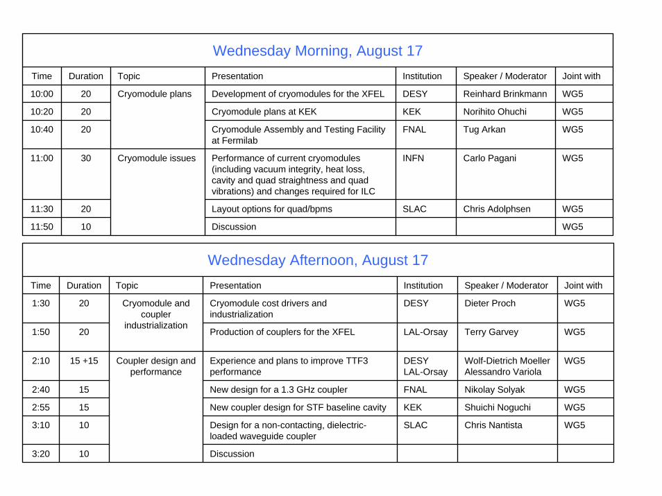
Wednesday Morning, August 17Time Duration Topic Presentation Institution Speaker / Moderator Joint with
10:00 20 Development of cryomodules for the XFEL DESY Reinhard Brinkmann WG5
10:20 20 Cryomodule plans at KEK KEK Norihito Ohuchi WG5
10:40 20 Cryomodule Assembly and Testing Facility at Fermilab
FNAL Tug Arkan WG5
11:00 30 Performance of current cryomodules(including vacuum integrity, heat loss, cavity and quad straightness and quad vibrations) and changes required for ILC
INFN Carlo Pagani WG5
11:30 20 Layout options for quad/bpms SLAC Chris Adolphsen WG5
11:50 10 Discussion WG5
Cryomodule issues
Cryomodule plans
Discussion 103:20
WG5Chris NantistaSLACDesign for a non-contacting, dielectric-loaded waveguide coupler
103:10
WG5Shuichi NoguchiKEKNew coupler design for STF baseline cavity152:55
WG5Nikolay Solyak FNALNew design for a 1.3 GHz coupler152:40
WG5Wolf-Dietrich MoellerAlessandro Variola
DESYLAL-Orsay
Experience and plans to improve TTF3 performance
Coupler design andperformance
15 +152:10
WG5Terry GarveyLAL-OrsayProduction of couplers for the XFEL201:50
WG5Dieter ProchDESYCryomodule cost drivers and industrialization
Cryomodule andcoupler
industrialization
201:30
Joint withSpeaker / ModeratorInstitutionPresentationTopicDurationTime
Wednesday Afternoon, August 17

Thursday Morning, August 18Time Durati
onTopic Presentation Institution Speaker / Moderator Joint with
8:30 20 Linac Simulations CERN Daniel Schulte WG1
8:50 20 Linac Simulations KEK Kiyoshi Kubo WG1
9:10 20 Linac Simulations FNAL Kirti Ranjan WG1
9:30 30 Coffee Break
10:00 20 Linac Simulations Cornell Jeff Smith WG1
10:20 20 Coupled orbit motion SLAC Roger Jones WG1
10:40 20 Lattice Configuration Studies FNAL Nikolay Solyak WG1
11:00 20 Wakefield simulation plans by the ACD group at SLAC
SLAC Zenghai Li WG1
11:20 20 Equivalent circuit simulation of high frequency modes
SLAC Roger Jones WG1
11:40 20 Discussion
Cavity Wakefields
Beam Dynamics
Beam Dynamics
WG1, WG5
Joint WG2/WG2/WG1 discussion of the various linac configuration options
BaselineConfiguration
1201:30
Joint withSpeaker / ModeratorInstitutionPresentationTopicDuration
Time
Thursday Afternoon, August 18

Objectives of Working-group ?
• Work to agree upon the baseline configuration choices. Use the Workshop to identify paths to decisions for unresolved issues with the expectation that these could be decided at one or two subsequent meetings during the fall of 2005.
• Start writing the BCD ! • Identify critical R&D topics and timescales
necessary for alternative options to the ILC Baseline Configuration that could have a significant impact on the performance or cost of the linear collider.
Make “Baseline Configuration” choices for linac componentsor at least identify BC “options” (criteria for doing this ? – established technique, proof of principle ??

Cavity Shape• Choice based on experience
– TESLA design shape:• Achieved 35 MV/m in 5 cavities (over 200 built).• HOM damping / wakes / Lorentz detuning well characterized.• 40 cavities currently running at TTF.• Two industrial suppliers (1000 will be used in XFEL).
• Choice based on potential cost savings– Low loss or reentrant:
• These designs potentially allow higher gradients, and if the iris diameter is reduced, require less stored energy and cooling (but produce higher wakes).
• Only one cell versions have been fabricated, achieving up to 45 MV/m. Will require several year, > 10 M$ effort to qualify design – KEK is actively pursuing this approach.