working with polycarbonate - bay plastics ltd
TRANSCRIPT

T e c h n i c a l M a n u a l
PALTOUGH
P A L R A M
®

Contents
3
4
5
12
13
13
23
24
34
36
40
42
I. PALSUN Product Group
II. Dimensions, Weights and Colors
III. Characteristics
IV. Selection of the Appropriate PALSUN Sheet
V. General Recommendations for Working With PALSUN
VI. Fabrication
VII. Finishing
VIII. Forming
IX. Assembly
X. Appendix 1: Chemical Resistance of PALSUN at Room Temperture
XI. Appendix 2: Adhesive and Sealants Compatible with PALSUN
XII. Appendix 3: Fault and Remedies in Thermoforming Practice
2
P A L R A M
PALTOUGHT e c h n i c a l M a n u a l

Table 1: PALSUN Products Range and Profile:
Notes:1. All the above sheets are supplied with a protective polyethylene (PE) film on both sides (one side upon request), with the UV protected side clearly marked. This film should be removed immediately after installation2. For transportation, handling and storage instructions and recommendations, please refer to “General Recommendation for Working with PALSUN ”. (page 13)3. PALSUN sheets are backed by a 10 years limited warranty, available upon request.4. Most PALSUN sheets are available in the transparent, translucent or opaque form, in a variety of colors, either standard or custom ordered.
8 PALSUN Mirror For indoor or outdoor useAlways installed with the mirror finish sideagainst a wall/ other solid protective material
Mirror coating on one side, co-extrudedUV protection on the other
7 PALSUN SOLAR CONTROL Integrated solar control sheet. Transmitscontrolled percentage of visible lightwhile reflecting long wave solar radiation(heat)
Available with co - extruded UV protectionon one or both sidesAvailable with 20, 35, or 50% lighttransmissionAvailable in Solar Metallic or Solar Ice
6 PALSUN FR Sheet with higher fire resistance rating(UL 94 V-0)
Available with co-extruded UV protectionon one or both sidesAvailable in combination with items1-5 and 7-8
5 PALSUN Matte Finish Matte finish on one side Available with co-extruded UV protectionon one or both sides
4 PALSUN Embossed Embossed on one side with smoothco-extruded UV protective layer on theother (unless requested otherwise)
Also available with co-extruded UV protectivelayer on both sides available textures:· Embossed· Prismatic· hair-cell
3 PALSUN PLUS Smooth sheet with co-extruded UVprotective layer onth sides
For applications with UV exposure onboth sides or exterior light fixtures
2 PALSUN Smooth sheet with co-extruded UVprotective layer on one side
For use in exterior glazing or overheadskylights and interior light fixtures
PALTUF UV stabilized, smooth sheet For indoor use onlyalso available with options 4-6 below
1
No. Product Product Description Remarks & Applications
A B C D
3
P A L R A M
PALTOUGH
I. PALSUN Product Group:
T e c h n i c a l M a n u a l

1 Custom color or tint, intermediate thickness, narrower width or longer sheets may be available upon special orders,
subject to stipulated quantities.2 Certain sheets are manufactured only in a limited range of dimensions, thicknesses, finishes or colors. Please consult your local Palram distributor before ordering.3 A Only a sample color chip, available from your local PALRAM distributor, depicts the actual true color or tint of a specific
PALSUN sheet.4 The final shade will depends on light transmission and sheet thickness. A thicker sheet will be manufactured in a lighter shade to yield the specified light transmission.5 Solar Control Colors
Table 2: Standard1 PALSUN Sheets2
4
II. Dimensions, Weights and Colors:
Dark GreenMist GreenBrick RedMacdonald redBlackDark BlueLight GrayRal 7035 – Pale GrayDark GrayBrownOff-WhiteMirror
Solar Metallic5
Solar Ice5
CreamRedyellowMist-GreenWhite OpalDiffuser
ClearSolar GrayBronzeRedBlueGreen
Thicknessmm x mm ( in. x in. )
1.0
1.5
2.0
3.0
4.0
5.0
6.0
8.0
10.0
12.0
0.04
0.06
0.08
0.12
0.16
0.20
0.24
0.32
0.40
0.47
1250
x 2
050
(50
x 80
)
·
·
·
·
·
·
·
·
·
·
1,190
1,785
2,380
3,570
4,760
5,950
7,140
9,520
11,900
14,280
0.24
0.36
0.49
0.74
0.97
1.22
1.44
1.95
2.73
3.28
H I J
1220
x 2
050
(48
x 96
)
2050
x 3
050
(80
x 12
0)
Transparent4 Translucent4 Opaque
Standard Colors3WeightStandard Dimensions
mm In. g/m2 psf
A B C D E F G
·
·
·
·
·
·
·
·
·
·
-
-
·
·
·
·
·
·
·
·
P A L R A M
PALTOUGHT e c h n i c a l M a n u a l

A. Typical Properties of PALSUN SheetsThe table depicting the typical properties of PALSUN sheets appears below. Note that some of the displayedproperties are typical to polycarbonate (the material PALSUN is made of) while others relate to a typical 3mm (1/8 in.) thick PALSUN sheet.
a. Conditions, units and values in U.S. Customary units are presented in the table within parentheses.b. All the results depicted in this table were obtained by following the indicated ASTM method except where another method is indicated by the appearance of this symbol (b).
Table 3: Typical Properties of PALSUN & PALTUF Sheet
5
III. Characteristics:
Conditions(U.S. Customary)a
Property ASTMMethodb
Units - SI(U.S. Customary)a
Value(U.S. Customary)a
PhysicalDensityWater AbsorptionMechanicalTensile strength at yieldTensile strength at breakElongation at yieldElongation at breakTensile Modulus of ElasticityFlexural ModulusFlexural Strength at YieldNotch Impact Strength IzodNotch Impact Strength CharpyImpact Falling WeightRockwell HardnessThermalLong Term Service TemperatureShort Term Service TemperatureHeat Deflection TemperatureVicat Softening TemperatureCoefficient of Linear ThermalExpansionThermal ConductivitySpecific Heat CapacityOpticalHazeLight TransmissionRefractive IndexYellowness IndexElectricalDielectric Constant
Dissipation Factor
Dielectric Strength Short TimeSurface ResistanceVolume Resistance
1.2 (75)0.15
65 (9,400)60 (8,800)
6>90
2,000 (290,000)2,600 (380,000)
100 (14,500)800 (15)800 (15)158 (117)125 / 75
-75 to +100 (-175 to +212)-75 to +120 (-175 to +250)
130 (265)150 (300)6.5 (3.6)
0.21 (1.46)1.26 (0.31)
<0.589
1.59<1
3.02.90.911
>30 (>770)5.1x10¹⁵
1.3x10¹⁷
24 hr. @ 23°C
10 mm/min (0.4 in./min)10 mm/min (0.4 in./min)10 mm/min (0.4 in./min)10 mm/min (0.4 in./min)10 mm/min (0.4 in. /min)
1.3 mm/min (0.052 in./min)1.3 mm/min (0.052 in./min)
23°C (73°F)23°C (73°F)
3 mm (0.12 in.) Sheet
Load: 1.82 MPa (264 psi)Load: 1 kg (2.2 lb)
3 mm (0.12 in.) Clear Sheet3 mm (0.12 in.) Clear Sheet
Clear Sheet3 mm (0.12 in.) Clear Sheet
50 Hz1 MHz50 Hz1 MHz
500 V/sKetleyKetley
g/cm3 (lb/ft3)%
MPa (psi)MPa (psi)
%%
MPa (psi)MPa (psi)MPa (psi)
J/m (ft·lbf/in.)J/m (ft·lbf/in)
J (ft·lbf)R scale / M scale
°C (°F)°C (°F)°C (°F)°C (°F)
10-5/°C (10-5/°F)
W/m°K (Btu-in./hr-ft2-°F)kJ/kg°K (Btu/lb°F)
%%
kV/mm (V/mil)Ohm
Ohm-cm
D-1505 D-570
D-638D-638D-638D-638D-638D-790D-790D-256D-256
ISO-6603/1b
D-785
D-648D-1525D-696
C-177C-351
D-1003D-1003D-542D-1925
D-150D-150D-150D-150D-149D-257D-257
P A L R A M
PALTOUGHT e c h n i c a l M a n u a l

B. Impact Strength:PALSUN sheets are manufactured from polycarbonate, the most versatile, toughest transparent thermoplastic.PALSUN has 200 times the impact strength of glass, offering excellent protection against riots and publicdisturbances, breaking & entering or acts of vandalism.
PALSUN can endure attacks by rocks, clubs, hammers and thrown objects, and still to retain its original shape,maintain its integrity with minimal indentations to its surface.The amount of damage depends on the object mass and energy, and sheet’s thickness. PALSUN sheets willretain these energy-absorbing proper t ies over a wide temperature range (50° to + 100° C).
Falling Dart MethodA uniform energy increment is employed during testing. Energy is decreased or increased by uniform incrementafter testing each specimen, depending upon the result (failed / not failed) observed for the former testedsample.
A 20 mm diameter dart, weighing 8 kg, with a rounded tip, is raised to a certain height and released to fall ona suitably sized sample.
Principles:Impact strength is determined by the known weight and height.Adjustment is done by altering height while using a constant mass.E50: 50% of Impact Failure Energy.The energy that will cause 50% of the tested samples to fail.N.B.**: No Break. The energy required to break the sample is greater than what the test instrument can deliver.
Table 4: Typical impact failure energy of PALSUN sheetsaccording to ISO 6603/1 1985(E)*
*ISO 6603/1: Determination of multi-axial impact behavior of rigid plastics
Figure 1: Falling dart impact testing device (Schematic)
6
1
2
911
8 3
107
6
5
41.2.3.4.5.6.7.8.
9.10.11.
Leveled floorStablized baseSupporting guidrailsLifting mechanismDisengagement mechanismGuidance barChangeable weight20 mm diameterhead falling dartTested specimenCaliberation barChangeable drop height
Type of Failure
2345681012
110150190290400N.B.**N.B.**N.B.**
100% Ductile100% Ductile100% Ductile100% Ductile100% Ductile
N.B.**N.B.**N.B.**
(mm) E50 (Joules)Sheet Thickness Energy at Failure
P A L R A M
PALTOUGHT e c h n i c a l M a n u a l

C. Optical Characteristics:Ultraviolet (UV) Radiation Blocking- PALSUN sheets completely block out potentially harmful UV radiationand a significant portion of infrared (IR) radiation. Over the visible light range, a typical 3 mm (1/8 in.) thickclear PALSUN sheet transmits about 89% (average) of incident light, as seen in Figure 3 below.
Figure 2: % Light Transmission of PALSUN & PALTUF Sheet (3 mm) Versus Wavelength
UV Visibile IR
Wavelength (nm)
250
300
350
400
500
600
700
800
1000
1400
1800
2200
2600
3000
100
80
60
40
20% L
ight
Tra
nsm
issi
on
Light Transmission Versus Thickness- Light transmission decreases slightly with increased thickness(see following graph).
Figure 3: PALSUN & PALTUF Sheet % Light Transmission Versus Sheet Thickness
% L
ight
Tra
nsm
issi
on
Sheet Thickness (mm)
92
91
90
89
88
871 2 3 4 5 6 7 8 9 10 11 12
D. Thermo-Optical PropertiesThermal conductivity is an important factor to consider when choosing a glazing material, due to its influenceon thermal efficiency and energy lose in winter (heating) or summer (air-conditioning). PALSUN sheets insulatebetter than glass, contributing to substantial energy conservation for single glazing.
Table 5: PALSUN vs. Glass K- Values in Single Glazing (W/m2 K) Sheet thickness
7
3.05.06.09.512.0
PALSUNK Value
GLASSK Value
(0.12)(0.20)(0.24)(0.37)(0.47)
Thicknessmm in
5.495.215.094.694.35
5.875.805.775.685.58
P A L R A M
PALTOUGHT e c h n i c a l M a n u a l
Definitions
Visible Light Radiation - The portion of the light spectrum whose wavelength ranges from 400 nm to 700 nm.
% Light Transmission (%LT) - Percentage of incident visible light that passes through an object .
% Light Reflection (%LR) - Percentage of incident visible light that strikes an object and returns in the form ofvisible light.
% Light Absorption (%LA) - Percentage of incident visible light that strikes an object and is absorbed by it.%LT + %LR + %LA = 100%
Solar Radiation - The solar spectrum ranging from 300 nm to 2400 nm. Included are UV, visible and NIR radiation.
% Direct Solar Transmission (%ST) - Percentage of incident solar radiation that passes directly through an object.
% Solar Reflection (%SR) - Percentage of incident solar radiation that strikes an object and is reflected.
% Solar Absorption (%SA) - Percentage of incident solar radiation that strikes an object and is absorbed by it.%ST + %SR + %SA = 100%
Total Solar Transmission (%STt) - The percent of incident solar radiation transmitted by an object which includesthe direct solar transmission plus the part of the solar absorption reradiated inward.
Total Solar Reflection (%SRt) - The percent of incident solar radiation rejected by an object, which includesthe solar reflectance plus the part of the solar absorption, reradiated outward.%STt + %SRt = 100%
Shading Coefficient (SC) - The ratio of the total solar radiation transmitted by a given material to that transmittedby normal g lass , whose l i gh t t ransmiss ion i s 87%. I t can be approx imate ly ca lcu la ted by :SC = 1.15 x ( %ST + 0.27 x %SA ) / 100%ST + 0.27 x %SA = %STt
SC = 1.15 x STt/100
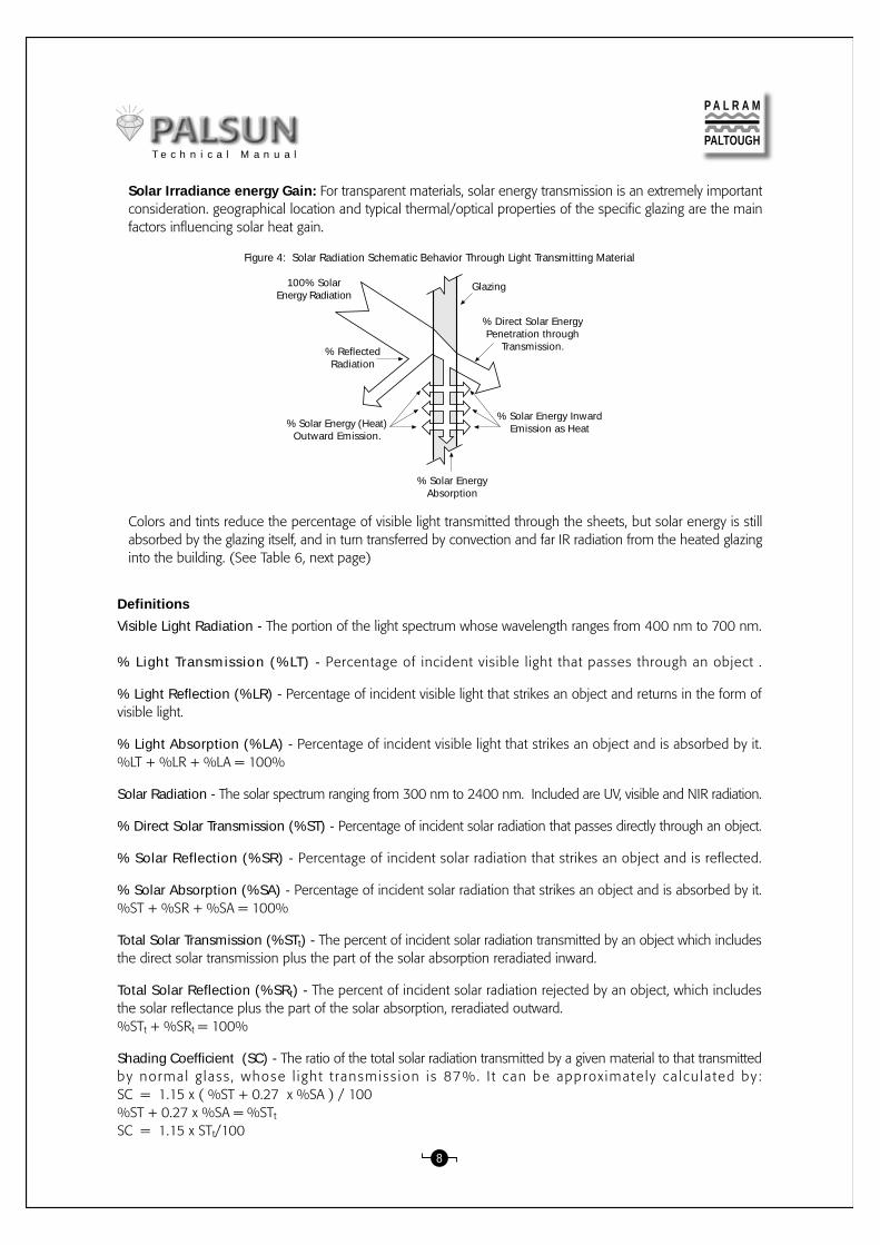
Solar Irradiance energy Gain: For transparent materials, solar energy transmission is an extremely importantconsideration. geographical location and typical thermal/optical properties of the specific glazing are the mainfactors influencing solar heat gain.
Figure 4: Solar Radiation Schematic Behavior Through Light Transmitting Material
100% SolarEnergy Radiation
% ReflectedRadiation
% Solar Energy (Heat)Outward Emission.
% Solar EnergyAbsorption
% Direct Solar EnergyPenetration through
Transmission.
% Solar Energy InwardEmission as Heat
Glazing
Colors and tints reduce the percentage of visible light transmitted through the sheets, but solar energy is stillabsorbed by the glazing itself, and in turn transferred by convection and far IR radiation from the heated glazinginto the building. (See Table 6, next page)
8
P A L R A M
PALTOUGHT e c h n i c a l M a n u a l

Physical treatments of one surface (embossing, matte) or the addition of a diffuser additive diminish glare anddazzle, preventing damage by direct irradiance. However solar energy is still transmitted through and increasesthe solar heat gain inside.
PALSUN Solar Control: PALSUN glazing with integrated Solar Control (no laminated layer to peel off!) and alight transmission of 20, 35, or 50%, reflects a large portion of far IR radiation (heat).
Figure 5b: Optical Properties of Solar Gray Sheet with20% Light Transmission
250
500
750
1000
1250
1500
1750
2000
2250
2500
Wavelength (nm)
% L
ight
Tra
nsm
issi
on, R
efle
ctio
n or
Abs
orpt
ion
100
90
80
70
60
50
40
30
20
10
0
Absorption
Transmission
Reflection
Figure 5a: Optical Properties of Solar Control Sheet with20% Light Transmission
% L
ight
Tra
nsm
issi
on, R
efle
ctio
n or
Abs
orpt
ion
100
90
80
70
60
50
40
30
20
10
0
250
500
750
1000
1250
1500
1750
2000
2250
2500
Wavelength (nm)
Transmission
Reflection
Absorption
9
Table 6: PALSUN - Solar Light and Radiation Transmission Properties
Clear
Bronze 50%
Bronze 35%
Bronze 20%
Solar Grey 50%
Solar Grey 35%
Solar Grey 20%
Solar Metallic* 50%
Solar Metallic* 35%
Solar Metallic* 20%
Standard White Opal
Standard White Opal
Standard White Opal
Standard White Opal
Standard White Opal
Standard White Opal
Standard White Opal
Standard White Opal
10
7
6
6
7
6
6
24
17
29
51
55
50
54
58
59
60
61
84
54
42
28
54
42
27
48
35
18
46
40
40
29
23
18
13
10
10
7
6
6
7
6
6
24
17
28
43
47
41
45
48
50
52
53
14
35
44
54
35
44
55
44
52
67
51
57
55
64
70
73
77
80
1.00
0.75
0.64
0.52
0.75
0.64
0.51
0.64
0.54
0.36
0.56
0.50
0.52
0.41
0.35
0.31
0.26
0.23
Product
88
50
35
20
50
35
20
50
35
20
45
35
45
39
28
19
14
11
3 (0.12)
All
All
All
All
All
All
All
All
All
0.8 (0.039)
1 (0.04)
1.5 (0.08)
2 (0.08)
3 (0.12)
4 (0.16)
5 (0.20)
6 (0.24)
Thicknessmm (in.)
% LTASTM
D-1003
%LRASTM
E424-71
%STASTM
E424-71
%SRASTM
E424-71
%SRtASTM
E424-71
SCASTM
E424-71
P A L R A M
PALTOUGH
*Solar Control
T e c h n i c a l M a n u a l

E. Weather ResistanceSolar UV radiation attacks many polymeric materials. The rate of deterioration and crazing on the exterior surfacewill vary for different polymers. Further erosion is accelerated by water, dirt, air pollution, chemicals etc. Theextent of attack depends on environmental factors such as location, altitude, local weather conditions, air pollutionetc.
The best initial indication is yellowing, followed by a significant reduction in light transmission and structuralstrength.
All PALSUN sheets (excluding those designated PALTUF, which are UV stabilized) are manufactured with a co-extruded, UV protective layer on one or two sides. This protective layer assures a long lifetime of service. PALSUNsheets retain their toughness and optical quality under intense UV exposure, with minimal reduction in theirproperties.
2000 hours of accelerated UV exposure [QUV- ASTM E-58 (88)] tests, simulating 20 years of exposure in hotsunny climates, cause only a minor decrease in light transmission and a slight increase in yellowness Indexfor PALSUN.The changes in UV stabilized PALTUF sheet are greater. The effect of QUV on 3 mm PALSUN & PALTUF sheetsappears in the following graphs:
F. Acoustic PropertiesThough only about half the weight of an equivalent glass panel, PALSUN glazing offers similar sound insulationproperties along with much higher impact strength.
These combined properties make PALSUN glazing the preferred material for see-through sound barriers: lightweight,easy to maintain or replace if necessary, highly transparent and vandal-proof.
The following table portrays the acoustic performance of PALSUN glazing versus glass:
Table 7: Acoustic Insulation According to DIN 52210-75 RW (dB)
10
PALSUN SheetSound Reduction (dB)
Glazing Sheet Thickness Glass PaneSound Reduction (dB)
242526283031
303031323334
(in.)(0.16)(0.20)(0.24)(0.31)(0.39)(0.47)
45681012
mm
P A L R A M
PALTOUGH
Figure 6a: % Light Transmission of PALSUN and PALTUF Sheet asFunction of QUV Exposure Hours
QUV Exposure Hours
% L
ight
Tra
nsm
issi
on
95
94
93
92
91
90
89
88
87
86
850 100 250 500 750 1000 1500 2000
PALTUF
PALSUN
Figure 6b: Change in Yellowness Index of PALSUN and PALTUFSheet
as Function of QUV Exposure Hours
QUV Exposure Hours
Chan
ge in
Yel
low
ness
Inde
x
10
9
8
7
6
5
4
3
2
1
00 100 250 500 750 1000 1500 2000
PALTUF
PALSUN
T e c h n i c a l M a n u a l

G. Flammability:General: As a thermoplastic, PALSUN eventually melts and burns under the intense heat of a blazing fire.However, PALSUN does not propagate flame, and is solidified and self-extinguished as soon as the direct flameis taken away. PALSUN doesn’t produce any toxic fumes or gases when it burns.
PALSUN FR: Flame retardant additives make the sheets virtually non-combustible. When the flame licks thesheet it only gets scorched and eventually melts, solidifying quickly when the direct heat source is removed.Drippings do not ignite other combustible materials, as they actually do not burn.
Smoke and heat extraction: In an actual, full-scale combustion, when PALSUN overhead glazing (as in skylights)is exposed to intense heat it will soften at 150° -160°C and produce apertures in the glazing, enabling heatand smoke to escape. Reduced temperatures inside the structure help to extinguish the f ire.
Flammability Classifications: PALSUN and PALSUN FR are classified as appears in the following table, basedon tests executed by certified independent testing laboratories.
H. Chemical Resistance:PALSUN sheets are compatible with many materials and chemicals, show limited resistance to others, and areincompatible with a third group, with which contact may be devastating. A more detailed discussion and a tabledepicting the resistance of PALSUN to a wide range of chemicals appear in Appendix 1 on page 36.
11
1Classification depends on thickness
Table 8: Fire Classifications listed according to the relevant codes or standards
Standard Description Classification
PALTUF/PALSUN2
PALTUF/PALSUN FR2
ProductB-1
Class 1YM-1M-2
Class 1V-0, V-1, V-21
-ClearClearClear
--
DIN 4102BS 476/7NSP 92501, 4NSP 92501, 4CSE RF 2/75/A CSE RF 3/77UL-94
NSP 92501, 4UL-94ASTM D-2863-87AU 1530.3-1982
-Clear/OpaqueClear/Opaque
-
M-1V-0L.O.I. = 30Iagnitability Index = 9Spread of Flame Index = 8Heat Evolved Index = 10Smoke Developed Index = 8
P A L R A M
PALTOUGH
2UL recognition for PALSUN and PALSUN FR clear. Fire Number E221255.
T e c h n i c a l M a n u a l

I. Adhesives and Sealants:Adhesives and sealants are a special class of substances often required during installation or fabricationof PALSUN. The guidelines for their use, appearing below, must be followed.
1. Use only sealants, adhesives, rubber packing, sealing strips & gaskets that are compatible with PALSUN andapproved by PALARM or its distributors.EPDM rubber sealing strips and gaskets are the preferred choice, (though the use of neoprene is permitted)due to a longer life expectancy and durability.
2. Use of sealants, adhesives and other sealing products not included in the recommended list (Appendix 3)must receive the Manufacturer's explicit approval, which can be obtained through your local distributor.Use of soft PVC gaskets and/or sealing strips is absolutely forbidden, as it is detrimental and may cause sheetfailure.
3. Use of materials that are not on the list, and/or which have not received the Manufacturer’s explicit approval,may harm the sheets and void all warranties and any responsibility of the Manufacturer for the performanceof PALSUN.
4. Your local distributor can provide additional information, and forward materials for testing and evaluation oftheir compatibility with the PALSUN sheets.
See Appendix 2 (page 40) for the recommended list of sealants, bonding materials and adhesives.See section 9. Assembly: (page 34) for additional specific details.
PALSUN sheets are manufactured in thicknesses of 1.0 to 12 mm.
A. PALTUF sheets are intended mainly for indoor use (transparent partitions, interior design applications, industrialshields, and Thermo-formed parts). They are also used in pavilions (exhibitions), or other temporary structures.Use of PALTUF sheets outdoors, for permanent applications, even in areas with mild UV radiation (NorthernEurope, USA, Canada and the like) is not recommended.
B. Thin PALSUN sheets are frequently used in temporary structures, (exhibitions, pavilions etc.).These productsmay also be used in conservatories or other horticultural / agricultural structures, where economy and lowercost are imperative. They are repeatedly used in Thermoforming applications, the forms generated render themr i g i d and su i t ab l e f o r spec i a l r equ i r emen t s , i n s i gn s and o the r adve r t i s i ng e l emen t s .
C. PALSUN sheets for Permanent Glazing Applications: The recommended permanent installation methodis inside a suitable supporting frame, made of metal (steel or aluminum), wood or rigid PVC profiles. Glazingthickness is determined according to the sash width of said frame, the wind/snow loads dictated by theenvironmental conditions and the building codes existing at the for the place of the said structure.
IV. Selection of the Appropriate PALSUN Sheet:
12
P A L R A M
PALTOUGHT e c h n i c a l M a n u a l

Handling & Storage:1. PALSUN sheets should be transported and stored horizontally, on a flat, sturdy pallet whose dimensions are
equal or larger than the largest of the sheets.
The sheets should be secured to the pallet during transportation and on-site handling. It is possible to stackthe sheets with the longer sheets at the bottom and the shorter on top, leaving no unsupported overhang.
2. When moving a pallet with a forklift, always use forks as long as the sheets’ width. Shorter forks used on awider pallet may cause damage to the sheets.
3. PALSUN sheets leave the factory in packages, wrapped in white, watertight polyethylene. The wrapping shouldbe removed as close to the actual time of installation (or use) as possible.Storage of the sheets should be in a covered, dry, ventilated place, away from direct sunlight and rain.
4. Avoid extended exposure to direct sunlight, which may cause excessive heat buildup. Long term heating maylead to softening of the protective polyethylene masking, fusing it to the sheet’s face and making removal difficultor even impossible.
5. Avoid leaving the sheets stored unwrapped. Dirt may accumulateon the sheets and/or their edges, attracted by electrostatic chargesin the sheets, necessitating extra time and labor for cleaning beforeinstallation.
6. Whenever necessary to store the pallet in the open, cover it withwhite opaque polyethylene sheet, cardboard or any other insulatingmaterial, taking care to cover the stack completely.
V. General Recommendations for Working With PALSUN:
A. General Guidelines:1. Tools:
PALSUN sheets can be fabricated with standard power tools for wood or metal, or some types of hand tools,providing they are smooth, well sharpened and have the required clearance for machining rigid plastics.Only speed regulated tools should be used. the highest possible speed that would not melt the sheet duringoperation, due to the heat buildup, gives the best results.High-Speed steel tools are adequate in most cases. Carbide-tipped tools are preferred for continuous productionlines.Tools should be set up so that just the cutting edges should get into actual contact with the fabricated material,to reduce frictional heat buildup.
2. Cooling: Cooling is not required under standard machining conditions. When high-speed machining is necessary, clean water or compressed air can be used to cool the material and tool, and remove the machining chips. Never use cooling oil or emulsions, as they may damage the PALSUN sheet. In order to avoid induced internal stresses generated by overheating, care must be taken to keep this heat
buildup to the absolute minimum.
VI. Fabrication:
13
Figure 7: Storing PALSUN Sheet
P A L R A M
PALTOUGHT e c h n i c a l M a n u a l

3. Size Regulation:Due to the high thermal expansion rate of palsun, which is considerably greater than that of metals, glass orconcrete, precision measurement checks should always be done at a fixed reference ambient temperature.
4. Protective Film (Masking):The PALSUN polyethylene (PE) protective masking may be left on the sheet during most regular fabrication,to prevent damage to the surface.
5. Fabrication Markings:When necessary, mark sheets to be fabricated on the protective masking. If, for some reason, it is necessary tomark directly on the bare face of the sheet, use wax pencils or felt tipped marking pens.
Marking the exposed surface by scratch marks with sharp objects may initiate fractures and induce failure underload.
B. Sawing & Cutting:A variety of power saws, either table mounted or portable can be used to saw PALSUN. Shearing or punchingare also possible.
Laser or water-jet cutting are less common but also possible techniques,.
1. Table Mounted or Portable Circular Saws:These types of saw are widely used to saw PALSUN.There are two major workshop types and one portable type:
A Moving Table, Fixed Blade Bench Saw: is preferable for long, straight sawing. Radial Arm Saw: is generally used for “cross-cut” (width) or diagonal sawing. Portable Circular Saw: usually restricted for use on site for straight cutting, is slower and not as accurate as
table saws. This type of saw may be attached underneath a special bench to function as an on-site, limitedoperation fixed table saw.Circular Saw Blades:Should be fine toothed hollow ground, or preferably carbide tipped, triple chipped (Alt 1 on next page) oralternate bevels (Alt 2 on next page), with minimal blade body contact with the cut material. Such blades canoffer clean, good quality cut.
14
a. Table 9: Generally Accepted Recommendations for Circular Blade Specifications:
Notes:1. 2 Possible alternatives (Alt 1, Alt 2 see next page) are supplied by different tools manufacturers as alternate beveled teeth for blades intended for cutting plastics, and both offer satisfactory cuts (line 3 in the table).2. For sawing thin gauge sheets of less than 2mm thickness, It is recommended to batch together 10 - 15 such sheets, with a thicker (3-4mm) bottom sheet for support.3. Shearing is a preferable option for cutting a single thin gauge sheet.
PropertyClearance angle αRake angle γAlternate double-bevel angle (Alt. 1) α°Alternate bevel angle (Alt. 2) β°Cutting speed (m/min.) (ft/min)Rate of feed (mm/sec.) (in./sec.)Thin gauge: (1.5-2.5 mm) Tooth pitch t (mm) (1/16”-3/32”) (Teeth per in.)Heavy gauge: (3.2-12 mm) tooth pitch t (mm) (1/8” - 1/2”) (Teeth per in.
No.123
4
5
6
7
Value10 – 20o
5 – 15o
45o
10 - 15o
1000 – 30003300 - 10000
3011/4
2.5 – 6.010 - 12
6.5 – 8.53 - 4
P A L R A M
PALTOUGHT e c h n i c a l M a n u a l

15
b. PALRAM Particular Circular Saw Cutting Recommendations:These recommendations are based on technical know-how, particular testsand vast practical experience accumulated during years of work.These recommendations are to be accepted only as general guidelines.
Table 10: Saw Blade Specifications for Cutting PALSUNup to 5mm Thickness.
B
B
A
t
AA
BBA
A
λ
Figure 8: Typical Circular Saw Blade (segment)
Table 11: Saw Blade Specifications for Cutting PALSUN 6 to 12 mm Thickness.
Notes:1. Teeth shapes sketches are not to scale. They should be considered to serve only as an indication.2. The PALSUN should be placed on a firm flat base and clamped into position during sawing.3. When sawing PALSUN it is recommended to leave the protective PE film on.4. If the cut sheet vibrates during sawing, cardboard sheet padding may be placed beneath it to absorb the vibrations.5. When sawing thin gauge palsun it is recommended not to cut single sheets by themselves, but saw a pack of 5-10 sheets at the time, clamped firmly together to a steady base.6. Low to moderate feed rate should be used when the sheets approach the blad, or vice versa. A feed rate that is too high can cause gumming, splitting or breaking of the sheet edges.
Diameter (mm / in.)No. of teeth in bladeThickness (mm / in.)Teeth anglesTooth appearance
Speed
300 / 1296
2.2 - 3.2 / 3/32 –1/8Rake- 10°, clearance 15°Alternating: Left –right
1800 – 2400 rpm
Diameter (mm / in.)No. of teeth in bladeThickness (mm / in.)Teeth anglesTooth appearance
Speed
350 / 14108
2.2 - 3.2 / 3/32 –1/Rake- 10°, clearance 15°
Alternating:
1800 - 2400 - pm
B-B A-A
AB45
Figure 9b: Alternate Teeth ConfigurationALT 2
A-AB-B
AB
ββ
Figure 9a: Alternate Teeth ConfigurationALT 1
P A L R A M
PALTOUGHT e c h n i c a l M a n u a l

16
2. Band Saw:
Band saws can be used for cutting PALSUN sheets of most thicknesses with acceptable results. Band saws areworkshop tools. In PALSUN fabrication they are mostly used to cut formed parts or irregular shapes. It is possibleto cut flat sheets in straight lines too, but in limited length and width, due to the tool’s limitations.
Thin gauge sheets are better sawed when stacked to a thickness of 10 -12 mm (0.4 - 0.5 in.) The preferred band saw blade should have slightly set teeth, with 10 – 20 mm (0.4 - 0.8 in.) blade widths.
Notes:1. A band saw is suitable for cutting curved lines and 3-dimensional, formed parts.2. For cutting a few formed objects of the same shape, they must be firmly clamped together.3. A band saw cutting usually yields rougher finished edge, which must be smoothed by sanding and polishing. An endless belt sander is a preferred tool for such an operation.4. We recommend using a circular saw for better-finished edges, whenever possible.
Figure 10: Typical Band Saw Blade Configuration
Table 12: Recommended Band Saw blade Properties:
tλ
No.123
4
5
6
PropertyClearance angle αRake angle λCutting speed (m/min.) (ft/min)Rate of feed (mm/sec.) (in./sec.)Thin gauge: (1.5-2.5 mm) Tooth pitch t (mm) (1/16”-3/32”) (Teeth per in.)Heavy gauge: (3.2-12 mm) Tooth pitch t (mm) (1/8” - 1/2”) (Teeth per in.)
Value10 – 20o
5 – 15o
1000 – 60001950 - 3300
2013/16
1.5 – 2.012 - 18
2.5 – 3.57 - 10
3. Portables: Jigsaw or Saber Saw:
Portable saws of these similar types use short movement, reciprocating blades, instead of one-directionorientation, continuous movement blades like those of circular or band saws, and are much slower in operation.
Jigsaw or saber saws are usually used on site, for limited cuts of irregular shape, or relatively short, straight lines. Jigsaw or saber saw blades are usually made of high-speed steel, with slightly set teeth. Specially designated blades, intended for rigid plastics, with alternate beveled teeth, are available. A slow feed rate (speed depends on sheet thickness) of about 1.5 mm/sec. and maximal reciprocating
speed (about 800 oscillations/min.), yields acceptable results for smoothness of cut. Due to the reciprocating blade movement, it is necessary to clamp the sheet down firmly when cutting, to
steady it during saw operation. Thin gauge sheets are better sawed stacked together to a total thickness of 10-12 mm (0.4 - 0.5 in.), with
the pack clampe down firmly to steady it during sawing.
Jigsaw or saber saw cutting usually result in inferior finish of the cut edges, worse than the results achievedby a circular saw. We recommend that sanding and polishing of the cut edges should be used as a regularpractice. An endless belt sander is the preferred tool for such an operation.
P A L R A M
PALTOUGHT e c h n i c a l M a n u a l

17
4. Sawing Tips:
Chipping and gumming are among the most common problems when sawing. Chipping: Various sized chips are broken of on both edges of the sawing line, leaving the cut edges rough anduneven. Gumming: Chips and splinters from the advancing saw blade overheat during the sawing process, melt and
create heaps of cooled down material in front of the blade and on both sides of the cut. The swarf sticks tothe edges leaving an ugly, rough edge finish, difficult to clean.Gummed material may also stick to the blade itself and cause seizure.The same uncontrolled heat that creates gumming, may also induce undue internal stresses along the edgesof the cut, necessitating annealing of the sheet.
Recommended Remedies: Choose the correct tooth size and pitch. Select a more appropriate saw speed. Lower the feed rate. Examine the sharpness of the blade. Examine the blade alignment. Cool the blade with compressed air when long cuts are required. Take frequent pauses during long production runs, to let the saw blade cool down. Begin sawing with the blade already running at the full recommended speed.
C. Shearing & Punching:1. Shearing:
A “Guillotine” power shear can be used for straight-line cuts. Easy, reasonably clean cuts can be obtained forthicknesses of up to 3 mm (1/8 in.). Beyond this, the material tends to draw, leaving uneven, stretched edgefinish.We recommend cutting only one single sheet at a time.
The shearing blade should be very sharp, with a single bevel of a 45o angle or less, or a hollow ground oneof approximately 30o. Recommended clearance between blade and anvil (bed) should be kept to very closetolerances as appear in the table below:
Table 13: Recommended gap between blade andanvil (bed) (5% of the sheet thickness)
The cut appearance may be adequate and suitable for many applications, but will not be similar in quality tothe cut with a circular saw. Rough-finished cut edges can be improved by sanding, same as recommendedfor the other types of sawing.
As there are many power shears manufacturers it is recommended that before making a purchase, one shouldinvestigate the intended instrument capability, and confer with the manufacturer in reference to plastic sheetscutting.For accurate cutting it is recommended to cut only single sheets. Cutting more than one sheet at a time maycause a break in one of the sheets, and / or yielding inaccurately sized parts. Blade maintenance is an importantfactor in achieving a quality cut.
mm1.01.52.02.53.0
In.0.0390.0590.0790.0980.118
mm0.050.0750.1
0.1250.15
In.0.00020.00030.00040.00050.0006
GapSheet thickness
P A L R A M
PALTOUGHT e c h n i c a l M a n u a l

18
Nevertheless, if you decide to cut a few sheets together and breakage occurs, please check the followingitems:1. Try cutting fewer sheets at a time.2. Check blade condition: sharpness, uniformity and alignment.3. Change the gap between the blade and the bed to a more suitable one.
Our experience shows that cutting quality can be checked in advance by a simple trial cutting of an 80g-papersheet:Acceptable - if the paper is cut cleanly, without tearing or crumpling.Unacceptable – if cut results in the paper torn and crumpled.
2. Punching:A technique usually used for cutting multiple holes and apertures (circular shaped or rounded) in thin or mediumthickness PALSUN sheets quickly and uniformly. It uses a mechanical press with a quick moving, limited depthcutting male punch and static female anvil (base). Recommended for a maximal thickness up to 3mm (1/8in.).
Punch cutting edges should be hollow-ground and very sharp for good quality cuts. Due to the tendency ofedge drawing when punching, resulting in “blown-in” aperture edges, this “hole shrinkage” should be takeninto consideration and provided for in cases of critically close tolerances. Exemplary values are about 0.2 mm(0.008 in.) shrinkage for a 12 mm (0.47 in.) hole, or 0.1 mm (0.004 in.) for a 6 mm (0.24 in.) hole, for a 3mm (0.12 in.) thick sheet.
3. Die Cutting:A technique stemming from punching, it is generally used for cutting out apertures or blanks in the sheet, inalmost any size or shape. The technique uses thin gauge rule type blades. For non-straight cuts asymmetricdouble beveled blades of 1mm (0.04 in.) thickness, are used, suitable for thicknesses of up to 1.5 mm (0.06in.).For thicknesses above that, a 2mm (0.08 in.) thick, double beveled, double-angled symmetric blades arerecommended. For straight edged cutting, a 1 mm (0.04 in.) thick, single bevel blade of 30° angle or less isrecommended.The backing for these blades is a pad made of nylon or high-density polyethylene. Precise alignment of bladesand pad is a must for obtaining satisfactorycuts.The blades are steel rules - thin steel ribbonswith one sharpened edge, 0.8 to 2.5 mm(0.03 to 0.1 in.) thick, 12-15 mm (0.5 in.)wide. They are generally mounted in slotscut into wood blocks and are relativelyinexpensive. The steel rule must be sharpenedor replaced fairly often.Figure 1 depicts two steel rule designs thatwork equally well in sheet gauges up to 2.5mm (0.1 in.). Hardness may vary from 45to 55 Rockwell C and depends on the degreeof bending required in fabrication.
Figure 11: Steel-rule die designs for cutting PALSUN sheet
30˚
15˚
0.08 cm (0.030")
5˚
10˚
0.03 cm(0.012")
0.11 cm(0.045")
0.05 cm(0.020")
30˚
30˚
P A L R A M
PALTOUGHT e c h n i c a l M a n u a l

19
Die cutting presses are to be adjusted to cut completely through the sheet with a stroke stopping just beforedamaging the cutting rule.A make-ready procedure is used to shim the die areas that must be shimmed, to ensure that it cuts throughthe sheet uniformly. The press should have a softer steel cutting plate (30-35 Rockwell C) to prevent contactwith the press bed.The cutting surface is normally a 0.5 mm to 3.2 mm (0.02-0.13 in.) thick steel plate. Test the die to ensurefull, uniform cut through the sheet, by alternating with shimming of rule areas until a satisfactory cut is obtained.Cut in the same place each time and keep the cutting dies as sharp as possible.
Knife EdgeHollow Ground
Approximately 30˚
Figure 13: Diagram of shearing assembly.
A die press must have adequate power to achieve the desired cut.
Apply Pressure
KnifeEdge
Hollow GroundApproximately 30˚
Figure 12: Diagram of steel rule die assembly.
4. Shearing & Punching Tips:a. Best results from these techniques are obtained by cutting a single sheet at a time. We recommend this.
Cutting a batch of sheets may result in breakage and/or imprecise dimensions. Nevertheless, if one is committedto such a procedure, We recommend a few trial runs with small samples, and consultation with the shearingmachine manufacturer.
b. A good indication for a quality cut is a trial cut of a regular 80 g paper page: If the outcome is a clean, straightcut, the actual result will be acceptable. If the cut paper is jagged, torn or crumpled- sharpen the blade and/oradjus the clearance and alignment.
c. We recommend that sanding and polishing of the cut edges should be used as a regular practice. Neverleave on rough or jagged edged apertures as that may lead on to crazing and imminent failure.
D. Cutting - Other Options:1. Laser Cutting:
A Hi-Tech thermal technique reserved mainly for complex contours.A CO2 industrial laser can cut sheets up to 5 mm (0.2 in.) thickness.
The cut can be done with or without masking, but often it needs pre-drying of the sheet in order to achievebubble-free cut edges. It can be used for cutting intricate holes and patterns cleanly and precisely.
Holes and cuts produced by a laser have slightly tapered edges with a finished appearance.
However, a laser cut in sheets thicker than 2 mm (0.08 in.) may result in scorch marks and discoloration(yellowing) of the cut edges. When a laser is used for cutting, careful consideration and treatment is requiredbefore and afterwards, to compensate for its inherent properties.
Annealing is recommended after laser cuttings, to remove the internal stresses created by the thermal process.
P A L R A M
PALTOUGHT e c h n i c a l M a n u a l

2. Routing:A versatile technique, enabling diversity of edge fabrications and trimming of PALSUN sheets, notably for partstoo large or of irregular shape for a band saw. With sharp two-flute straight cutters it can generate very smoothedges.
The feed rate should be slow, to avoid excessive heat buildup and shattering. When routing, the moving object, whether the sheet or router, should be guided by a suitable jig. A jet of compressed air can be used to cool the bit and the sheet at the spot of cutting and assist in chip removal.
Static bench routers:Fast, strong and stable, for complex and accurate straight-line fabrications.
Portable routers:Less powerful, for smaller or on site jobs. Also used for trimming and edge fabrications of irregular shapes. Canperform certain small milling jobs like butt shaping on rectangular or round apertures or tongue and groovebutt finish on thicker sheets.
Applications:Primary edge finishing: Quick and accurate trimming or finishing of straight-edged or curved cut PALSUN sheets. Easily produced straightedge corners or curved butts. Preparation of varied lap and butt joint fabrications.
Tooling: Routers: Universal, commercially available equipment. Routing cutters: new metalworking cutters, kept at utmost sharpness.
20
Table 14: Cutters’ configurations:Clearance AngleRake AngleRouter speed (w/o load)Cutting SpeedFeed Rate
5 – 10°0 – 10°15,000 – 22,000 rpm100 – 500 m/min (330 -1640 ft./min)0.1 – 0.5 mm/rev (0.004 - 0.07 in.rev)
Routing and milling tips For clean, smooth routing work ensure cutter’s sharpness and faultless alignment beforestarting work.Compressed air jet cooling following the cutting head improves the culter’s speed, cut quality and blows theswarf away.Let the tool reach its maximum (unloaded) operating speed before commencing work.
Milling & Joining:A portable router, with suitable cutters, can be used for small milling jobs.
A standard woodworking jointer-planer, preferably with carbide or high-speed blades/cutters, can be used fortrimming, acquiring good quality edge finish.Avoid excessive stock removal, which may result in shattering or rough edges. A cut of 0.4 mm (0.016 in.) orless per pass is recommended.
P A L R A M
PALTOUGHT e c h n i c a l M a n u a l

21
F. Drilling:1. General Indications:
Drill bits: Regular, new high-speed steel twist drills, or new carbide-tipped drills are suitable for drilling holesin PALSUN sheets o f va r ious th icknesses , as long as they a re sharpened we l l . They a reused mainly for bores up to 12 mm(1/2 “) diameter.
E. Finishing Recommendations for Well Done Sawing and Cutting:Unintended saw marks, rough or jagged corners, or uneven, drawn edges created by imperfect shearing mayresult in crazing and cracking, that can develop further to failure under load.
We recommend finishing the edges of cut PALSUN sheets (or all types of plastics) by finishing the edges to asmooth appearance.
This will ensure that no cracks will develop from the irregularities at the edges.Smoothing techniques are discussed in Section VII (page 23).
Larger holes may be drilled by flat, chisel edged drill blades with a triangular cutting tip, similar to those usedin woodworking, kept always very sharp.Rake angle should be about 5° to avoid side friction. They are usedmainly for bores from 12 to 20mm (1/2 “ to 13/16 “).Commercially available cutting cups or circle cutters of several types can be used for performing large roundapertures.
Speed: Decrease the drill’s speed as hole diameter and / or sheet thickness gets larger. Drilling speed may varydue to actual conditions.Feed rate: May vary due to actual conditions.
γ ο
αο
βο
Figure 14a: Regular drill bit
αο
Figure 14b: Flat chisel edged drill blade
Table 15: Drilling Speed and Feed Rate Change in Accordance with Bore Diameter.
Hole Diameter Drill Speed Feed Rate
1/81/4
13/3219/3225/32
0.120.240.40.60.8
0.012-0.0280.012-0.0280.004-0.028
0.0280.028
36101520
1500 - 1800800 – 1500500 – 1000350 – 700250 - 350
0.03 – 0.070.03 – 0.070.01 – 0.07
0.070.07
mm/rev in./revrpmmmin. in.
P A L R A M
PALTOUGHT e c h n i c a l M a n u a l
22
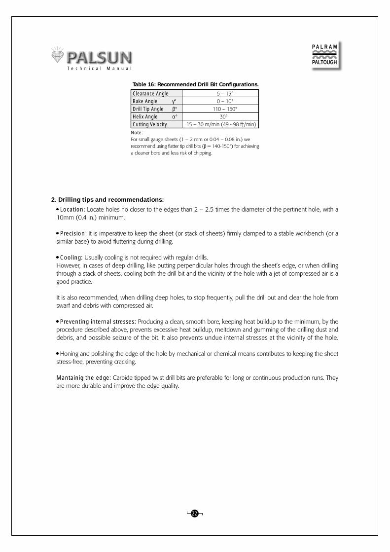
Table 16: Recommended Drill Bit Configurations.
Note:For small gauge sheets (1 – 2 mm or 0.04 – 0.08 in.) werecommend using flatter tip drill bits (β = 140-150°) for achievinga cleaner bore and less risk of chipping.
2. Drilling tips and recommendations:
Location: Locate holes no closer to the edges than 2 – 2.5 times the diameter of the pertinent hole, with a10mm (0.4 in.) minimum.
Precision: It is imperative to keep the sheet (or stack of sheets) firmly clamped to a stable workbench (or asimilar base) to avoid fluttering during drilling.
Cooling: Usually cooling is not required with regular drills.However, in cases of deep drilling, like putting perpendicular holes through the sheet’s edge, or when drillingthrough a stack of sheets, cooling both the drill bit and the vicinity of the hole with a jet of compressed air is agood practice.
It is also recommended, when drilling deep holes, to stop frequently, pull the drill out and clear the hole fromswarf and debris with compressed air.
Preventing internal stresses: Producing a clean, smooth bore, keeping heat buildup to the minimum, by theprocedure described above, prevents excessive heat buildup, meltdown and gumming of the drilling dust anddebris, and possible seizure of the bit. It also prevents undue internal stresses at the vicinity of the hole.
Honing and polishing the edge of the hole by mechanical or chemical means contributes to keeping the sheetstress-free, preventing cracking.
Mantainig the edge: Carbide tipped twist drill bits are preferable for long or continuous production runs. Theyare more durable and improve the edge quality.
Clearance AngleRake Angle γ°Drill Tip Angle β°Helix Angle α°Cutting Velocity
5 – 15° 0 – 10° 110 – 150° 30°15 – 30 m/min (49 - 98 f†/min)
P A L R A M
PALTOUGHT e c h n i c a l M a n u a l

23
A. General Comments:1. Reasons, Means and Targets:
The final step in fabrication, finishing improves both the practical and esthetical properties of PALSUN sheetprior to assembly.
2. Grinding & Polishing:This is mostly done as a part of edge preparation.Practical objective: Rough, uneven, untended edges may be starting points for crazing and cracks after the PALSUNsheet is installed and subjected to day by day exposure to wind loads, UV radiation and thermal expansion &contraction, not to mention man-made punishment.Aesthetic objective: Nicely finished, smooth edges are a must for a quality appearance of the finished product,often installed with exposed edges.
3. Decorating:A type of finishing intended mostly for aesthetic appearance or for display purposes. Executed by painting,printing, films or hot stamping.
B. Grinding / Sanding:General: A primary stage in edge finishing, rough or gagged edges and cutting tool marks created by a saw,shearing machine or a router, can be removed by grinding.
Grinding / Sanding Recommendations:A belt sander, equipped with a 400-500 grit belt, running at 20 - 30 m/sec (65 - 100 ft./sec), is the preferredoption, applying low contact pressure during operation. Wet sanding and waterproof belts are preferable, as theyprevents heat buildup, sanding dust accumulation, and prolong sanding belt life.
A reciprocating or orbital sander can also be used, but it can be applied only by the dry sanding method.
Manual Sanding can also be used, wet or dry, working with successive grit size abrasive paper (at first 100,then 280-grit silicon-carbide, and finally 400-600 grit sandpaper).
C. Polishing:On the progressive stage in edge finishing, the sanded (or ground) edges are polished to a smooth finish.
1. Basic Polishing:It is done by abrasive-charged revolving wheels, made of cloth, leather or bristles. When used with a coolant,peripheral speeds of 10-15 m/sec (30-50 ft./sec) are recommended. When the wheel is operated dry lowerspeeds should be used.
Ashing: A polishing method in which wet rubbing compound like #00 pumice is applied to a rotating loosemuslin wheel. Higher peripheral speeds of 20 - 22 m/sec (50 - 70 ft./sec) can be used, as overheating is nota problem in this technique.
Buffing: A finishing step in which grease or wax filled abrasive bar is applied to rotating muslin wheel. Loosebuffs are used for irregular shapes or for entering crevices. Usual buffing compounds are tripoli, rouge or otherfine silica.
VII. Finishing:
P A L R A M
PALTOUGHT e c h n i c a l M a n u a l

24
2. Advanced Polishing:It is achieved by using flannel or chamois wheels, with wax compounds with the finest abrasives such as whitingor levigated alumina. The wax fills the fine scratches or imperfections and protects the polished surface.
3. Final Polishing:For removing even the minute scratches remaining and achieving a slick, glossy edge finish, solvent finishingwith MEK or Methylene Chloride can be used.
a. (Recommended) A small container with the solvent is heated to about 40 °C (104 °F) and the vapor createdruns out through a rubber hose, and is passed over near (about 50 mm or 2 in. distance) the roughly polishededges. A small amount of vapors is enough to achieve highly glossy edge surface. A repeated application ispossible if required.
b. (Optional) A cloth soaked with MEK or Methylene Chloride, run carefully over the edges, can also produceacceptable results.
c. To minimize humidity blush after drying, add about 10% of a slow drying component (such as diacetonealcohol) to the basic solvent.
d. A note of precaution: when working with volatile or toxic solvents appropriate ventilation and respiratory protection are cardinal.
A. Cold Forming:1. Cold Curving:
a. PALSUN sheets can be cold bent or curved, within their minimal permitted bending radius, without damagingtheir mechanical performance. Moreover, based on our experience and observations, the internal stressesinduced by curving give them extra strength and rigidity in both directions, as in pre-stressed concrete elements.
b. Rigidity and support spans increase progressively as the curve radius is reduced (down to the minimal permittedradius). A shallow curve should be considered virtually the same as a flat panel, while a deep curve may addsignificantly to the bridging ability.
2. Brake Forming:
a. General Notes:
1) PALSUN sheets can be cold-bent in a straight line (line bending). Standard metalworking tools, like a brakepress, may be used for bending. The bending process results in a permanent plastic deformation. the degreeand quality of this change depend on the thickness of the PALSUN sheet, the final bending angle required,and the actual tools used.
2) When brake forming of PALSUN is applied, the internal elastic stresses induced along the bent line reducethe mechanical properties, UV resistance, and chemical resistance of the sheet along the bending line. Werecommend using the process for less demanding applications, and protecting the cold bent areas of thesheet from contact with aggressive chemicals or excessive forces.
3) Annealing (page 34) can reduce the residual stress level induced by the cold bending process, improvingthe sheet’s mechanical properties.
4) The maximum angles that can be obtained using this process depend on PALSUN sheet thickness, and theextent of the internal elastic strain. We recommend a 24-48 hours delay for sheet’s stress relaxation afterbending.
VIII. Forming:
P A L R A M
PALTOUGHT e c h n i c a l M a n u a l
25
In order to achieve the desired angle, the sheet has to be bent 20-40 degrees in excess of that angle, dependingon the angle and sheet thickness. During stress relaxation period immediately after bending, the bent sheetwill expand and regain the required shape.
5) Certain types of sheets are not suited for either cold or thermal forming, like PALGARD (mar protected sheet).This type is supplied with a tough, scratchproof finish, which can not be bent and must be installed as is.
b. Practical Recommendations & Work Instructions:
1) Preparations of the PALSUN Sheets and Tooling for Bending:a. Cut the sheet to its required pre-bent size, after careful design.
We recommend leaving the protective film on both sides during the cutting, edge preparation and cold bendingoperations.
b. Sand and polish the sheet’s edges to a very smooth finish. Rough edges or the tiniest fissure may initiatecracks and fractures at the vicinity of the bending lines, due to internal stresses induced by the bending process.
c. We recommend doing preliminary bending tests on small samples of the same (or varied) thickness of theintended sheet, and try a few different values of excess bending. After arriving at a satisfactory result you canstart production.
d. It is advised to use special tooling, like blades and anvils, designed for plastic sheet bending. Standardmetalworking blades and anvils are not necessarily suitable for bending plastic sheets.
For plastics, we recommend using a special bending blade with a straight, rounded business edge. The edgeradius should be about 4-6 mm (0.16 to 0.24 in.). The thicker the sheet, the larger edge radius required.The anvil channel outer “banks” (corners) should be rounded. Both blade and anvil are to be smooth andpolished, with no projections, irregularities or rough edges.
The anvil channel for plastics bending is different than the metalworking one. It has wider, flat bottom andmuch steeper “banks”.
2) Cold Bending Fabrication:
a. Bending a sheet with an UV protected side (the printed protective film side) on the exterior of the bendgets best results. Therefore, unless otherwise requested, lay the sheet to be bent with the printed side facedown.
b. For optimal results perform the brake forming quickly, with additional 20-40 degrees, as explained above,then leave for stress relaxation for 1-2 days.
3) Installation:
a. Cold bent polycarbonate is more sensitive to mechanical or chemical abuse in the vicinity of the bend.Therefore we recommend a design that offers better protection for bent areas from any detrimental influence.
b. Avoid putting additional strain on bent parts, like forcing a bent angle in or out to fit into an existing frameworkposition.
P A L R A M
PALTOUGHT e c h n i c a l M a n u a l
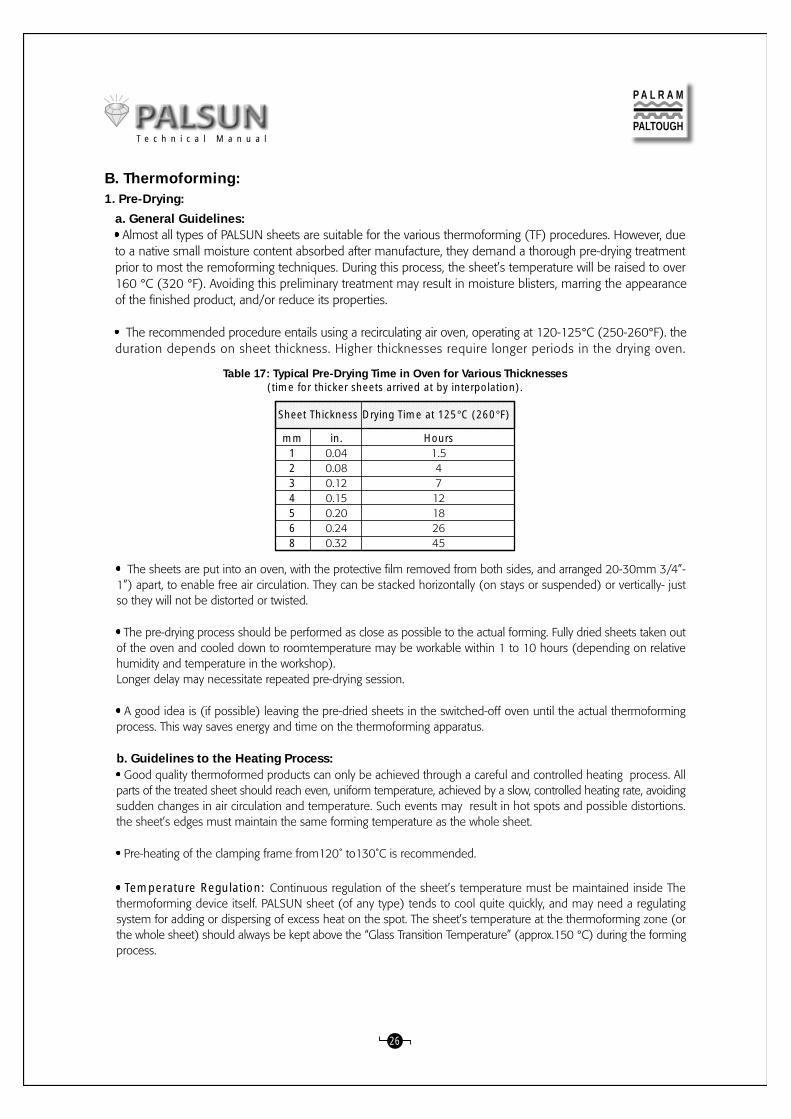
Table 17: Typical Pre-Drying Time in Oven for Various Thicknesses(time for thicker sheets arrived at by interpolation).
B. Thermoforming:1. Pre-Drying:
a. General Guidelines: Almost all types of PALSUN sheets are suitable for the various thermoforming (TF) procedures. However, due
to a native small moisture content absorbed after manufacture, they demand a thorough pre-drying treatmentprior to most the remoforming techniques. During this process, the sheet’s temperature will be raised to over160 °C (320 °F). Avoiding this preliminary treatment may result in moisture blisters, marring the appearanceof the finished product, and/or reduce its properties.
The recommended procedure entails using a recirculating air oven, operating at 120-125°C (250-260°F). theduration depends on sheet thickness. Higher thicknesses require longer periods in the drying oven.
in.0.040.080.120.150.200.240.32
Hours1.54712182645
Sheet Thickness Drying Time at 125°C (260°F)
mm1234568
26
The sheets are put into an oven, with the protective film removed from both sides, and arranged 20-30mm 3/4”-1”) apart, to enable free air circulation. They can be stacked horizontally (on stays or suspended) or vertically- justso they will not be distorted or twisted.
The pre-drying process should be performed as close as possible to the actual forming. Fully dried sheets taken outof the oven and cooled down to roomtemperature may be workable within 1 to 10 hours (depending on relativehumidity and temperature in the workshop).Longer delay may necessitate repeated pre-drying session.
A good idea is (if possible) leaving the pre-dried sheets in the switched-off oven until the actual thermoformingprocess. This way saves energy and time on the thermoforming apparatus.
b. Guidelines to the Heating Process: Good quality thermoformed products can only be achieved through a careful and controlled heating process. All
parts of the treated sheet should reach even, uniform temperature, achieved by a slow, controlled heating rate, avoidingsudden changes in air circulation and temperature. Such events may result in hot spots and possible distortions.the sheet’s edges must maintain the same forming temperature as the whole sheet.
Pre-heating of the clamping frame from120˚ to130˚C is recommended.
Temperature Regulation: Continuous regulation of the sheet’s temperature must be maintained inside Thethermoforming device itself. PALSUN sheet (of any type) tends to cool quite quickly, and may need a regulatingsystem for adding or dispersing of excess heat on the spot. The sheet’s temperature at the thermoforming zone (orthe whole sheet) should always be kept above the “Glass Transition Temperature” (approx.150 °C) during the formingprocess.
P A L R A M
PALTOUGHT e c h n i c a l M a n u a l

27
Forcing the sheet to form at a lower temperature may induce detrimental internal stresses, reducing the sheet’simpact resistance and increasing its chemical sensitivity. Internal stresses are invisible and can be detected only bypolarized light.
Annealing may solve the problem, but it is a complicated process, which is inefficient or impossible in most cases.
Protective Polyethylene (PE) masking in Thermoforming: Special PE masking is available for TF and shouldbe ordered for sheets intended for TF. This masking may be left on the sheet using most thermoforming methods,and peeled off at the last moment. In case of regular masking, it should be removed prior to the thermal treatment,otherwise it may fuse into the sheet’s face.
2. Hot-line bending:
a. General Guidelines:1) Description: A simple bending technique, used for forming local, straight line, one axis bent parts (suchas corners, boxes, and machine guards). This type of bending is usually preferable (if possible) to cold line-bending.
2) The process: A bending device with localized heaters on one or two sides of the sheet to be bent is used.The “sandwiched“ two-sided heating method is preferable, since it retains the same temperature on both sidesat the time. a one-side heater method requires turning the sheet over a few times during the heating period,to maintain optimal temperature on both sides.
b. Steps & Indications: One-sided heating method may suffice for sheets up to 3 mm (0.12 in.). Thicker sheets or more demanding
cases require using two-sided heating. Keeping control of the sheet’s temperature limits of 155-167 °C (31-332 °F) is of the utmost importance. Forcing the bend at lower temperatures will render the sheet fragile at the bend. This simple bending processenables working with regular sheets, without pre-drying. Experimenting with small samples before final executionis highly recommended.
Base
AdjustableThermostat
Top & BottomHinges
Power
Angle CaliberationUnits both sides
Bending blocks
Top & BottomHeating Elements
PALSUN Sheetto be bent
Figure 15: Heat bending device
P A L R A M
PALTOUGHT e c h n i c a l M a n u a l

PE Masking: When preparing for bending of regularly cladded sheets- peel off the masking on both sides ofthe sheet along the bend line for about 100 mm (4 in) on each side in TF prepared sheets. It is possible toprocess the sheet with the masking on, up to 5 mm (0.2 in) thickness. For sheets of 6 mm thickness or morethe PE masking should be removed along the bending line, as described above. Always test a few samplesbefore proceeding to production.
Heaters: Linear IR (Infrared) or resistance wires strip heating elements are used, preferably with heat reflectors.The width of the heated zone depends on the number of elements used, the spacing between them theirspecific thermal output and the distance from the target sheet.
Bending process: When the sheet has reached the required temperature the heaters are to be switched off.The sheet, held in pivoted clamps, preferably equipped with a caliper, is then bent to the required angle andsecured there until it cools down and sets.
Note: It is recommended to perform the bend a few degrees tighter than the required angle, as it may “goback” a little after cooling down. The desired angle may be reached after a few trials.
Cooling is to be done in ambient air, taking care to avoid sudden drafts. These can cause distortion of thefinal product.
Minimal Hot-Line Bending Radius is 3 times the thickness of the bent sheet. Larger radii can be achievedby widening the heated zone.
C. Notes for Consideration:Local hot line bending (or any other localized heating, for the matter) induces internal stresses in the finishedpart, reducing the chemical resistance of the element at the bending line zone. Such treatment is thereforerecommended for use in less demanding environments.
Localized heating and cooling expansion/contraction characteristics are unpredictable in many cases. Shortelements (up to 1.00 m or 3.0 ft) usually stay straight enough. Longer elements may distort to a concave shape(the outer edges are longer than the line-bent side due to uneven contraction).
This phenomenon can be corrected or reduced by simple jigs or frames, which hold the part in the right positionduring the cool ing period. Anneal ing (see special paragraph) may also correct this problem.
It is always advised to fabricate experimental test samples to check feasibility of the bending operation.
3. Drape Forming:
a. Description:
A simple technique, using a single positive (male) or negative (female) mold, on which a heated PALSUN sheetis placed. The sheet, softened by appropriate thermal processing, sags and conforms to the shape of the moldunder its own weight, or by slight mechanical pressure applied by hand. Drape forming is generally used toachieve simple, uniaxial, large curvature thermal forming.
b. The Process
Two main techniques, differing by the position of the mold during the first stage.
1) 1st Method: The sheet (without masking) is placed on top of the mold in its basic, flat state. Both sheetand mold are then slid into a hot-air circulating oven and heated to about 150-155?C (300-312?F). When thesheet (and mold) reaches the required temperature it sags and drapes over the heated mold. Both are thenpulled out of the oven and quickly helped, by gloved hands, to conform more precisely to the mold. It is thenallowed to cool down.
28
P A L R A M
PALTOUGHT e c h n i c a l M a n u a l

2) 2nd Method: The sheet is placed into a hot-air circulating oven (without masking), and heated to about150-155 °C (300-312 °F). When the sheet reaches the required temperature it is quickly pulled out of theoven and placed on top of the mold. there the sheet sags, aided quickly by the gloved helping hands, andtakes the accurate shape of the mold. For better results we recommend pre-heating the mold to about 80 -100 °C (175 -210 °F) before putting the heated sheet on top. Then it is, likewise, allowed to cool down.
c. Vacuum Assisted Drape Forming: The technique can be assisted by vacuum and is then very similar indetail to the male (positive) straight vacuum forming.
29
Figure 16: Vacuum Assisted Drape Forming
VacuumSeal
Vacuum
Mold
B. Once the sheet has formed a seal aroundthe mold, a vacuum is drawn to pull thesheet tightly against the mold surface.
Thickest Areas
Thin Areas
Formed Part
C. Final wall thickness distributionin the molded part.
A. Clamped, heated PALSUN sheet can bepulled over the mold, or the mold can beforced into the sheet.
Clamp
PALSUN Sheet
Heater
Seal
Vacuum
Mold
d. Notes for Consideration: (These notes exclude the vacuum assisted drape forming).
1) There is no need for pre-drying in this technique, due to the lower operating temperature it requires.
2) The lower operating temperature leaves the exterior surface harder, helping to keep it mar free, with betteroptical quality.
3) The emphasis on quick operation during the final finishing touch to the heated sheet derives from the rapidcooling and setting properties of the PALSUN sheet once taken out of the oven.
e. The Molds:
1) Regular molds can be made of metal (steel, aluminum or other) or wood, as long as it can stand thetemperature inside the oven without visible distortion. The upper surface is usually covered by heat resistantfelt, which will not mar the exterior sheet surface facing the mold face.
2) Premium molds: Finished products requiring premium optical quality (like visors, police shields, vehiclessafety glazing etc.) need molds with very smooth, glossy, heat resistant upper surface. They can be made ofpolished steel, aluminum, glazed ceramics or glass.
P A L R A M
PALTOUGHT e c h n i c a l M a n u a l

4. Vacuum Forming:
a. General Guidelines:
Vacuum forming is the most versatile and widely used thermoforming process. The equipment required issimpler and less costly to operate than most pressure or mechanical thermoforming techniques. Good resultsare quite easily attained with pre-dried sheets and decent vacuum-forming equipment.
Reduction in Thickness:The Vacuum forming procedure generally stretches parts of the processed sheet to smaller thickness at variedareas (according to the system chosen). Always take this into consideration when choosing the primary sheetthickness.
Molds:Prototype or Limited Production Molds can be prepared of smoothed plaster, hardwood, reinforced epoxyor polyester resins (or a combination of them).High quality finish or full production run molds for yielding quality results or quick release operation toolshave to be heated to working temperatures of 120 - 130 °C. Higher mold temperature (within the limits) getsbetter product’s finish. Polished aluminum or steel are preferable materials.
Mold Corners:Design the mold with rounded “sharp” corners, with radii at least as large as the processed sheet thickness, toavoid excess thinning or webbing during forming.
Mold Release:Good release of the molding can be achieved by designing the mold with a draft angle of at least 4 to 6 degreeson the upright walls. Allow for a molding shrinkage of about 1%.
Air Evacuation Through the Mold:Vacuum forming operates on suction principle, creating vacuum underneath the processed sheet. Suction isobtained through small holes put into the mold face. To prevent marking the molding, holes diameter on theexterior should not surpass 0.8 mm (0.031 in.). On the interior side of the mold the hole could be enlarged,to speed up air evacuation.
Male (positive) or Female (negative) Molds:Vacuum forming can be performed on male or female molds, using different equipment and technique, withdifferent results.
Male Mold Forming: A heated sheet is lowered over a protruding mold and stretched down to the bottom,then air is evacuated through the mold and creates vacuum, which “sucks” the stretched sheet until it clingsto the mold face.(Actually similar to vacuum assisted drape forming).
Female Mold Forming: A heated sheet is placed over the cavity of the negative mold, then air is sucked throughthe mold. The vacuum “sucks” the sheet until it clings to the inner face of the mold.
Male Mold:Its use results in thicker bottom and thinner walls. The internal finish of the final product is better. This type ofmold is suited for deeper drawing (up to 4:1 depth to diameter ratio). It usually has a single protrusion, in asimple or more elaborately shaped forming. This is a relatively complex and slow technique needs a longerproduction cycle.
30
P A L R A M
PALTOUGHT e c h n i c a l M a n u a l

Female Mold:Its use results in thinner bottom and thicker walls and edges. The exterior finish of the final product is better.It can be used in a single cavity (simple or elaborate), especially suitable for multi-cavity, smaller spacing moldings.Its use results in edges thinning during deep draw, thus most suitable for simple, shallow, quick release designs,with a relatively fast production cycle.
Automatic Vacuum-Forming Machines:These are preferable in use, gripping the worked-on sheet on all sides during the process. It is notably importantwhen working on thin [1 or 2 mm (0.04 or 0.08 in.)] thick sheets.Thin sheets tend to shrink up to 5% duringthe thermal processing and the cooling period, and must be firmly held in a fixed size frame.
When a sheet is inserted into the vacuum-forming machine, verify that the UV protected side is properly orientedto suite the finished product. Vacuum forming usually requires pre-drying of the sheets. It can also be carriedout without pre-drying, in shallow molds and careful treatment. In that case the sheet temperature should notexceed 160 °C (320° F). Uneven heating, resulting in localized hot spots, over 160-165 °C (320-330° F), maycause bubbles to appear at the overheated zone.
b. Various Vacuum Forming Techniques:
1) Straight Vacuum Forming;
In straight vacuum forming, the PALSUN sheet is clamped in a frame and heated until it reaches an elastic state.It is then placed over the female mold cavity, and air is then sucked out of the cavity by vacuum. The atmosphericpressure forces the hot sheet against the contours of the mold. When the PALSUN sheet has cooled downsufficiently, the formed part can be removed from the mold.Thinning at the upper edges of the part usually occurs with relatively deep female molds. The hot sheet beingdrawn first to the mold center causes thinning. The sheet area at the edges of the mold stretch the most, thusbecomes the thinnest section of the formed item. Straight vacuum forming is normally used for simple, shallowdesigns. See the figures below.
31
Figure 17: Straight Vacuum Forming
B. Plastic sheet cools as it contacts themold.
C. Areas of the sheet that touchthe mold last are the thinnest.
Formed Part
Thick Areas
Thin Cornersand Edges
Mold
Vacuum
PALSUN Sheet
A. A clamped, heated sheet is forceddown into the mold by air pressure aftera vacuum is drawn in the mold.
SealMold
Vacuum
PALSUN Sheet Clamp
Other Thermoforming Techniques: Other, more specialized, thermoforming techniques use vacuum alongwith other power assistance, and others depend on different mechanical principles. These techniques weredeveloped for typical applications or to achieve certain results:
2) Matched Mold Forming: A heated sheet is placed between two matching male/female heated molds,which are then pressed to each other. Trapped air pockets are vented by vacuum through holes in the molds.System enables very good detailing of surfaces, but is relatively costly due to need of accurate tooling and closertolerance.
P A L R A M
PALTOUGHT e c h n i c a l M a n u a l

B. Vents allow trapped air to escapeas the mold closes and forms the part.
A. The heated PALSUN sheet can be clamped over thefemale die, as shown, or draped over the mold form.
Ram
Male Form
Female Form
Trapped Air Vents
32
3) Trapped-Sheet Contact-Heat Pressure Forming:The process is based on similar principles as vacuum forming, except that both air pressure and a vacuum assistare used to force the PALSUN sheet into a female mold. It uses lower working temperature, and has a quickerproduction cycle. Other benefits are better dimensional control and finer finish.
The figures below depict the steps in the process.
4) Plug Assisted forming: Available in varied pressure/vacuum systems for deeper drawings and better controlover wall thickness:
5) Pressure-Bubble Plug-Assist Vacuum Forming:The pressure-bubble plug-assist vacuum forming technique is used when a sheet is to be formed into deep articlesthat must have good thickness uniformity. The framed sheet is heated, then controlled air pressure is used to createa bubble. (See the figures below.) When the bubble is stretched to a predetermined height, the male plug-assist(normally heated) is lowered to force the stretched sheet into the cavity. Plug speed and shape can be varied forimproved material distribution.
P A L R A M
PALTOUGH
A. A flat, porous plateallows air to be blownthrough its face.
B. Air pressure frombelow and a vacuumabove force the sheettightly against theheated plate.
C. Air is blown throughthe plate to force thePLSUN into the moldcavity.
D. After forming, additionalpressure may be exerted.Steel knife can be used forseal and subsequent trimif additional pressure isexerted at this stage.
Figure 19: Trapped-Sheet Contact-Heat Pressure Forming
Blow Plate
Seal
Mold
Vacuum
Air On
Air On
Vacuum
SteelKnifeor Seal
Formed Part
Figure 18: Matched-Mold Forming
T e c h n i c a l M a n u a l
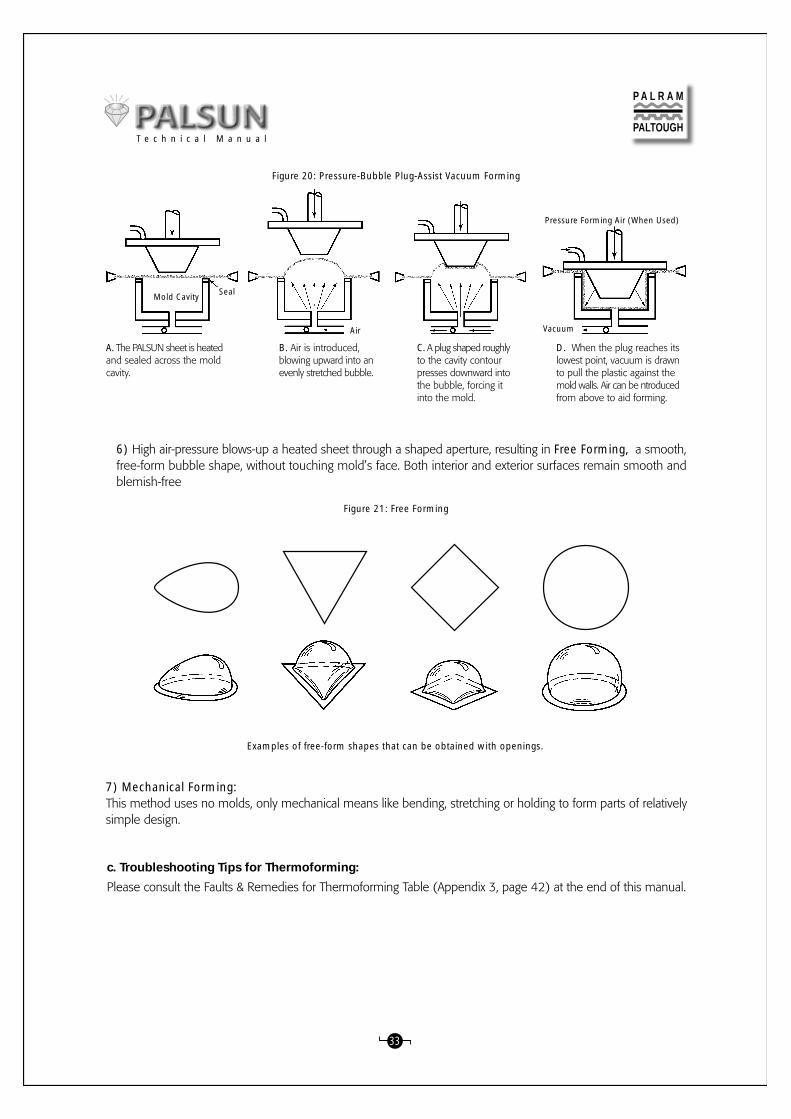
33
A. The PALSUN sheet is heatedand sealed across the moldcavity.
B. Air is introduced,blowing upward into anevenly stretched bubble.
C. A plug shaped roughlyto the cavity contourpresses downward intothe bubble, forcing itinto the mold.
D. When the plug reaches itslowest point, vacuum is drawnto pull the plastic against themold walls. Air can be ntroducedfrom above to aid forming.
Mold Cavity Seal
Air
Pressure Forming Air (When Used)
Vacuum
Figure 20: Pressure-Bubble Plug-Assist Vacuum Forming
6) High air-pressure blows-up a heated sheet through a shaped aperture, resulting in Free Forming, a smooth,free-form bubble shape, without touching mold’s face. Both interior and exterior surfaces remain smooth andblemish-free
Examples of free-form shapes that can be obtained with openings.
7) Mechanical Forming:This method uses no molds, only mechanical means like bending, stretching or holding to form parts of relativelysimple design.
Figure 21: Free Forming
P A L R A M
PALTOUGH
c. Troubleshooting Tips for Thermoforming:
Please consult the Faults & Remedies for Thermoforming Table (Appendix 3, page 42) at the end of this manual.
T e c h n i c a l M a n u a l

34
5. Annealing:
Cold fabrication, or various thermoforming systems of the PALSUN sheets, may induce detrimental internals t r e s se s , wh i ch may e ven tua l l y c au se f a i l u r e , and ha ve t o be r e l i e ved b y annea l i n g .
Annealing is achieved by heating the fabricated objects evenly in an air-circulating oven up to 120 to 130 °C,and leaving them inside for about an hour for every 3mm thickness. (Example: 6 mm thick formed part- 2hours of “baking”.)
After the “baking” period, the parts should be left to cool down slowly to the ambient temperature. It is preferableto let it cool inside the closed oven.
6. Hot Tips about PALSUN Thermoforming:
Consistent part-to-part uniformity is better ensured if the sheet blanks prepared for the thermoforming processare cut from the basic sheet always at the same direction.
Best results in thermoforming are achieved when parts are heated to temperatures just above the HDT (150°C- 300 °F).
Thermoforming parts below the HDT temperature induces undue internal stresses.
Secure the cooling area for thermoformed parts against undue drafts. Uneven cooling may result in warpingand/or curling of parts.
Assure precise and systematic control over oven temperature and heating time.
PALSUN MR and FR are not recommended for use in thermoforming. The bending and stretching involved duringthe process will break and crack the protective coating.
Joining, Bonding, Fastening & Sealing.
A. JOINING - General Guidelines:PALSUN sheets, or parts made of them, can be assembled and joined to each other, or to other materials, withthe help of varied techniques and materials.Assembly can be executed by bonding, cementing, or mechanical fastening.Each technique has its variations, with different properties, merits and shortcomings. Certain preparations (bymilling or routing) may be required improve the quality of the joints both aesthetically and practically.
1. Mechanical Joints:Machine Nuts & Bolts or Self-Tapping Screws must be supplemented by wide washers and EPDM gasketsfor padding and load spreading (see more comprehensive description further on).
Riveting: Same indication for washers and gaskets as in screws. (see more comprehensive description furtheron).
IX. Assembly:
P A L R A M
PALTOUGHT e c h n i c a l M a n u a l

35
2. Chemical Joints:PALSUN sheets can be joined to each other or to other materials by bonding or cementing, with or withoutprior preparation. Most such joints are suitable for relatively small to medium sized jobs. We present here afew possible options:
Joint Design: The joint details should be thought over carefully, verifying that the bonding area spreads theintended loads equally, and the major stresses are either in tension or shear, so as to minimize separationand peel stresses.
Lap Joints: They are most frequently used technique, in various designs, especially in relatively thin gaugeparts. The sheets’ edges overlap and are bonded together (in the suitable variation-fits for all sheet thicknesses).Some variations require routing or milling at the joints for proper execution.
Figure 22: Typical Lap JointsB,D,F, superior to A,C, E, / G,H corner lap joints
Adhesive Tape Bonding
Thin PALSUN Parts
Pressure
Two sides adhesive tape
Lap joints config.
P A L R A M
PALTOUGH
H
Angled Exterior Lap Joint
PALSUN
G
Bonding done by Solvent, Cement or Adhesive
Interior corner lap jointPALSUN
PALSUN
F
Double Lap / butt Joint
PALSUN
D
Double Scraf Lap Joint
E
Single lap / butt joint
PALSUN PALSUN
A
Tapered simple lap joint
B
Double joggled Lap joint
C
Double butt lap joint
T e c h n i c a l M a n u a l

The mechanism of chemical attack on polycarbonate sheets differs significantly from the mechanism of corrosionof metals. Corrosion of metals results in a gradual loss of surface material as a result of electrolytic action by therelevant chemicals. In the cases where chemical attack on polycarbonate sheet occurs, all or a portion of a rangeof effects can be observed. Ethylene choride, chloroform, tetrachloroethane, m-cresol, pyridene and other chemicalscan cause partial dissolution of polycarbonate. Swelling agents include benze, chlorobenzene, tetralin, acetone,ethyl acetate, acetonitrile and carbontetrachloride. Additional effects include color change and/or whitening. Theseeffects may not always lead to product failure, especially for non-loaded sheets. Nevertheless, the level of measuredmechanical properties will be reduced. The most critical effect of chemical attack is stress cracking or crazing, whichmay range in size from being visible to the naked eye to being only observable under a microscope. Stress crackswill always result in sheet failure which will eminate from areas of greatest stress (screws, fixings, bends, etc.)
Polycarbonate sheets are generally not recommended for use with acetone, ketones, ethers, and aromatic andchlorinated hydrocarbons in addition to aqueous or alcoholic alkaline solutions, ammonia gas and its solutions andamines.
Polycarbonate is resistant to mineral acids, many organic acids, oxidizing and reducing agents, neutral and acid saltsolutions, many greases, waxes and oils, saturated, aliphatic and cycloaliphatic hydrocarbons and alcohols, withthe exception of methol alcohol. The resistance of polycarbonate to water may be described as good up toapproximately 60 °C. At higher temperatures, degradation occurs, the extent of which depends on time andtemperature. Polycarbonate should therefore not be exposed for long periods of time to hot water. However, briefcontact with hot water has no effect. For example, polycarbonate tableware can be washed over 1000 times in adishwashing machine with no adverse effects being observed.
The table that appears on the following pages lists the resistance of polycaronate sheet to a number of commonlyencountered chemicals and other corrosive media at room temperature. (Information on chemical resistance athigher temperatures will be supplied upon request). Where the chemical resistance varies with concentration, theresults of tests at different concentrations is presented. The information on chemical resistance is based on ourresearch and experience. (Note that information on compatable adhesives and sealants can be found in aseparate leaflet which will be supplied upon request) It serves as a basis for recommendation. PALRAM Industriesdoes not guarantee chemica l res is tance unless spec i f i c separa te documentat ion is suppl ied .
For chemicals and corrosive media not depicted in the list, please contact your PALRAM representative. He will placeyou in contact with the PALRAM R&D & Technology Department.
The table on the following pages uses the following key:R - ResistantLR - Limited Resistance (gradual attack over time may occur)N - Not Resistant (rapid attack or attack over short time period will occur)
36
X. Appendix 1: Chemical Resistance of PALSUN at Room Temperature
T e c h n i c a l M a n u a l
P A L R A M
PALTOUGH
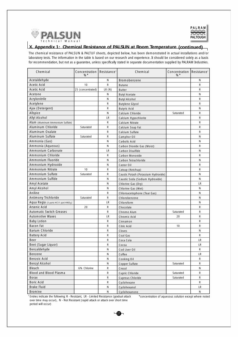
1 Entries indicate the following: R - Resistant, LR - Limited Resistance (gradual attackover time may occur), N - Not Resistant (rapid attack or attack over short timeperiod will occur)
*concentration of aquesous solution except where noted
37
P A L R A M
PALTOUGH
(continued)X. Appendix 1: Chemical Resistance of PALSUN at Room TemperatureT e c h n i c a l M a n u a l
The chemical resistance of PALSUN & PALTUF sheets, depicted below, has been demonstrated in actual installations and/orlaboratory tests. The information in the table is based on our research and experience. It should be considered solely as a basisfor recommendation, but not as a guarantee, unless specifically stated in separate documentation supplied by PALRAM Industries.
Chemical Resistance1 Chemical Concentration%*
Resistance1Concentration%*
AcetaldehydeAcetic AcidAcetic AcidAcetoneAcrylonitrileAcetyleneAjax (Detergent)AllspiceAllyl AlcoholAlum (Aluminum Ammonium Sulfate)
Aluminum ChlorideAluminum OxalateAluminum SulfateAmmonia (Gas)Ammonia (Aqueous)Ammonium CarbonateAmmonium ChlorideAmmonium FluorideAmmonium HydroxideAmmonium NitrateAmmonium SulfateAmmonium SulfideAmyl AcetateAmyl AlcoholAnilineAntimony TrichlorideAqua Regia (3 parts HCl:1 part HNO3)
Arsenic AcidAutomatic Switch GreasesAutomotive WaxesBaby LotionBacon FatBarium ChlorideBattery AcidBeerBeet (Sugar Liquor)BenzaldehydeBenzeneBenzoic AcidBenzyl AlcoholBleachBlood and Blood PlasmaBoraxBoric AcidBrake FluidBromine
10
25 (concentrated)
Saturated
Saturated
10
Saturated
Saturated
20
6% Chlorine
N
R
LR (N)
N
N
R
R
N
LR
R
R
R
R
N
N
LR
R
N
N
R
R
N
N
N
R
R
LR
R
R
LR
R
R
R
R
R
R
N
N
N
N
R
R
R
R
N
N
Saturated
Saturated
20
10
Saturated
Saturated
Saturated
N
R
R
N
R
R
N
R
R
R
R
R
N
N
R
N
R
N
R
R
N
N
LR
N
N
N
N
R
R
R
R
R
N
R
LR
LR
R
LR
R
R
N
R
R
R
LR
N
BromobenzeneButane
Butter
Butyl Acetate
Butyl Alcohol
Butylene Glycol
Butyric Acid
Calcium Chloride
Calcium Hypochlorite
Calcium Nitrate
Calcium Soap Fat
Calcium Sulfate
Camphor Oil
Carbolic Acid
Carbon Dioxide Gas (Moist)
Carbon Disulfide
Carbon Monoxide
Carbon Tetrachloride
Castor Oil
Catsup (Ketchup)
Caustic Potash (Potassium Hydroxide)
Caustic Soda (Sodium Hydroxide)
Chlorine Gas (Dry)
Chlorine Gas (Wet)
Chloroacetophone (Tear Gas)
Chlorobenzene
Chloroform
Chocolate
Chrome Alum
Chromic Acid
Cinnamon
Citric Acid
Cloves
Coal Gas
Coca Cola
Cocoa
Cod Liver Oil
Coffee
Cooking Oil
Copper Sulfate
Cresol
Cupric Chloride
Cuprous Chloride
Cyclohexane
Cyclohexanol
Cyclohexanone

*concentration of aquesous solution except where noted1 Entries indicate the following: R - Resistant, LR - Limited Resistance (gradual attackover time may occur), N - Not Resistant (rapid attack or attack over short timeperiod will occur)
38
P A L R A M
PALTOUGH
R
R
R
LR or R
N or LR
N
R
N
N
LR
LR
N
N
R
LR
N
N
N
N
N
N
LR
R
R
R
R
LR
R
N
R
R
N
R
R
R
R
R
R
R
R
R
R
N
R (N)
R
R
R
R
N
R
DDT
Dekalin
Dextrose
Detergent (most)
Developing Solutions
Diamyl Phthalate
Diesel Fuel
Diethyl Ether (Ethyl Ether)
Dimethyl Formaldelhyde (DMF)
Dinonyl Phthalate (plasticizer)
Doctyl Phthalate (plasticizer)
Dioxane
Diphyl 5,3
Ethanol (Ethyl Alcohol) and Water
Ethanol (Ethyl Alcohol)
Ethyl Amine
Ethyl Acetate
Ethyl Bromide
Ethyl Chloride
Ethylene Chlorohydrin
Ethylene Dichloride
Ethylene Glycol (Antifreeze)
Ferric Chloride
Ferrous Sulfate
Fish and Fish Oils
Formalin
Formic Acid
Freon TC and TF
Freon (all others)
Fluorosilicic Acid
Fruit Juices and Pulp
Gasoline
Gear Oil
Glazers Putty
Glucose
Glycerine
Glycerol
Glycols
Glutaraldehyde
Grease, Automotive (Most)
Heptane
Hexane
Hydrazine
Hydrochloric Acid
Hydrofluoric Acid
Hydrogen Peroxide
Hydrogen Sulfide
Iodine (aqueous solution)
Iodine
Inks (Most)
95
Pure
Saturated
10%
30%
20 (Concentrated)
20
30
5
20
Saturated
Saturated
Saturated
Saturated
Pure
20
10
10
10 Saturated
LR
LR
N
R
N
LR or R
R
R
R
R
N
LR or R
R
R
R
R
R
R
R
R
R
R
LR
N
N
N
N
N
R
R
LR or R
R
N
R
R
N
N
N
N
R
R
R
LR
N
R
R
R
R
LR
N
Isoamyl Alcohol
Isopropyl Alcohol
Kerosene
Lactic Acid
Lacquers and Thinners
Laundry Detergents (Most)
Ligroin (Hydrocarbon Mixture)
Lime Solution (2%) or paste
Liquors or Liqueurs
Linseed Oil
Loctite
Lubricating Oils (Most)
Machine Oils (Most)
Magnesium Chloride
Magnesium Sulfate
Manganese Sulfate
Margarine
Mayonaise
Meat
Mercuric Chloride
Mercury
Methane
Methanol (Methyl Alcohol)
Methyl Cellosolve
Methyl Ethyl Ketone (MEK)
Methylmethacrylate
Methylamine
Methylene Chloride
Milk
Mineral Oil
Motor Oils (Most)
Mustard
Naphtha (Staniol)
Nickel Sulfate
Nitric Acid
Nitrobenzene
Nitropropane
Nitrous Oxide
Nutmeg
Oleic Acid
Onions
Oxalic Acid
Oxygen
Ozone
Paprika
Paraffin
Pentane
Pepper
Perchloric Acid
Perchloroethylene
Chemical Resistance1 Chemical Concentration%*
Resistance1Concentration%*
(continued)X. Appendix 1: Chemical Resistance of PALSUN at Room Temperature
T e c h n i c a l M a n u a l

*concentration of aquesous solution except where noted1 Entries indicate the following: R - Resistant, LR - Limited Resistance (gradual attackover time may occur), N - Not Resistant (rapid attack or attack over short timeperiod will occur)
39
P A L R A M
PALTOUGH
Perroleum
Perroleum Ether
Perroleum Oils (Refined)
Phenol
Phosphoric Acid
Phosphorous Oxychloride
Phosphorous Pentoxide
Phosphorous Trichloride
Polyethylene
Polyethylene Glycol
Potassium Acetate
Potassium Aluminum Alum (Sulfate)
Potassium Bichromate
Potassium Bromate
Potassium Bromide
Potassium Chloride
Potassium Cyanide
Potassium Dichromate
Potassium Hydroxide
Potassium Metabisulfite
Potassium Nitrate
Potassium Perborate
Potassium Perchlorate
Potassium Permanganate
Potassium Persulfate
Potassium Rhodanide
Potassium Sulfate
Propane
Propargyl Alcohol
Propionic Acid
Propionic Acid
Propyl Alcohol (1-Propanol)
Pyridene
Salt
Silicone Grease
Silicone Oil
Silver Nitrate
Sililcofluoric Acid
Soap (Ivory)
Sodium Bicarbonate
Sodium Bisulfate
Sodium Bisulfite
Sodium Carbonate
Sodium Chlorate
Sodium Chloride
Sodium Chromate
Sodium Hydroxide
Sodium Hypochlorite
Sodium Nitrate
Sodium Sulfate
10
25
Saturated
Saturated
Saturated
4
Saturated
10
10
10
Saturated
Saturated
20
Concentrated
30
Saturated
Saturated
Saturated
Saturated
Saturated
5% Chlorine
Saturated
LR
LR
R
N
R
R
LR
N
R
R
LR
R
R
R
R
R
N
R
N
R
R
R
R
R
R
R
R
R
R
R
N
LR
N
R
R
R
R
R
R
R
R
R
R
R
R
LR
N
R
N
R
Saturated
Saturated
<50 (50<70)
10
30
20
LR
R
R
R
R
N
R
R
R (LR)
N
N
R
R
LR
N
N
N
N
R
R
R
N
R
R
LR
N
N
LR
N
R
LR
R
R
R
R
N
R
R
R
R
R
N
R
R
R
N
R
R
R
R
Sodium Sulfide
Sodium Thiosulfate
Spindle Oil
Stannous Chloride
Starch
Styrene
Sugar
Sulfur Dioxide (Gas)
Sulfuric Acid
Sulfurous Acid
Sylfuryl Chloride
Tapping Oil
Tartaric Acid
Tear Gas (Chloroacetophenone)
Terpineol
Tetrahydrofuran
Tetralin
Thiophene
Thyme
Titanium Tetrachloride
Tobacco
Toluene
Transformer Oils
Transmisssion Fluid
Trichloroacetic Acid
Trichloroethylamine
Tricholorethylene
Trichloroethylphosphate
Tricresylphosphite
Trisodium Phosphate
Turpentine
Urea
Vacuum Pump Oil
Vanilla
Vanillin
Varnish
Vasilene
Vegetable Juices
Vegetable Oils
Vinegar
Water (Demineralized or Sea)
White Spirit
Wine, Whiskey, Vodka, Rum, Cognac
Witch Hazel
Worcester Sauce
Xylene
Zinc Chloride
Zinc Oxide
Zinc Stearate
Zinc Sulfate
Chemical Resistance1 Chemical Concentration%*
Resistance1Concentration%*
(continued)X. Appendix 1: Chemical Resistance of PALSUN at Room TemperatureT e c h n i c a l M a n u a l

The information depicted in this leaflet is based on testing carried out in our laboratory or informationobtained from a variety of sources over the years.The Palram laboratory will test the compatibility ofmaterials as a service to our customers.
Note that PALRAM Industries is not responsible for the results obtained when using these materials.
It is imperative that the manufacturer’s instructions be strictly followed. This includes following therequired safety procedures. Some products contain organic solvents which have the potential todamage t he hea l t h o f t he u se r i f p rope r s a f e t y p ro cedu re s a r e no t f o l l owed .
If you have any comments or questions, feel free to contact your PALRAM distributor.
P A L R A M
PALTOUGH
40
AX 9330 No. 1HE 1908HE 17017Extru-FixTensol 12Evo-Tech TU 1908Plio-Grip 600055416MA 3940MA 3940LH3054 BN 811767Dichloromethane (Methylene Chloride)Bison PURAcrifix A-118Acrifix A-190F 104Scotch weld DP 110Scotch weld DP 190Jet Melt 3736
ApolloEngineering ChemicalsEngineering Chemicals
EVO-PLAS / EVODEEVO-PLAS / EVODEEVO-PLAS / EVODE
GoodyearIPS WELD-ONIPS WELD-ONIPS WELD-ON
ITW PlexusITW Plexus
Loctitemost chemical suppliers
PerfectaRohmRohm
Sasa Chemicals3M3M3M
Blue – PU adhesive2 component PU2 component PU
solventsolvent
2 component PU
2 component PUsolventsolvent
2 component2 component
transparent-fast adhesionsolvent
1 component PUsolvent mixturesolvent mixture
AdhesiveHot meltHot meltHot melt
Product Name Manufacturer Material Type
Adhesives
X. Appendix 2: Adhesives and Sealants Compatible with PALSUN
T e c h n i c a l M a n u a l
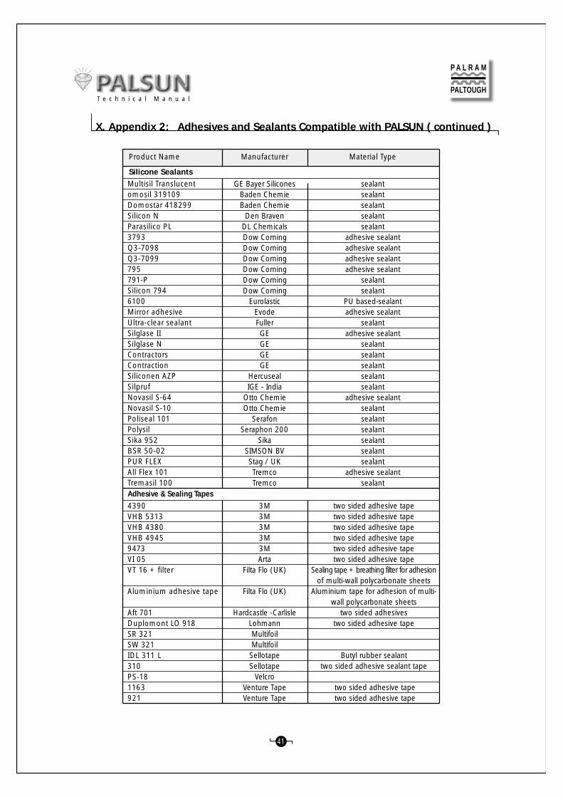
41
4390VHB 5313VHB 4380VHB 49459473VI 05VT 16 + filter
Aluminium adhesive tape
Aft 701Duplomont LO 918SR 321SW 321IDL 311 L310PS-181163921
3M3M3M3M3MArta
Filta Flo (UK)
Filta Flo (UK)
Hardcastle -CarlisleLohmannMultifoilMultifoilSellotapeSellotape
VelcroVenture TapeVenture Tape
two sided adhesive tapetwo sided adhesive tapetwo sided adhesive tapetwo sided adhesive tapetwo sided adhesive tapetwo sided adhesive tape
Sealing tape + breathing filter for adhesionof multi-wall polycarbonate sheets
Aluminium tape for adhesion of multi-wall polycarbonate sheets
two sided adhesivestwo sided adhesive tape
Butyl rubber sealanttwo sided adhesive sealant tape
two sided adhesive tape two sided adhesive tape
Silicone SealantsMultisil Translucentomosil 319109Domostar 418299Silicon NParasilico PL3793Q3-7098Q3-7099795791-PSilicon 7946100Mirror adhesiveUltra-clear sealantSilglase IISilglase NContractorsContractionSiliconen AZPSilprufNovasil S-64Novasil S-10Poliseal 101PolysilSika 952BSR 50-02PUR FLEXAll Flex 101Tremasil 100
GE Bayer SiliconesBaden ChemieBaden Chemie
Den BravenDL ChemicalsDow CorningDow CorningDow CorningDow CorningDow CorningDow Corning
EurolasticEvodeFullerGEGEGEGE
HercusealIGE - India
Otto ChemieOtto Chemie
SerafonSeraphon 200
SikaSIMSON BVStag / UKTremcoTremco
sealantsealantsealantsealantsealant
adhesive sealantadhesive sealantadhesive sealantadhesive sealant
sealantsealant
PU based-sealantadhesive sealant
sealantadhesive sealant
sealantsealantsealantsealantsealant
adhesive sealantsealantsealantsealantsealantsealantsealant
adhesive sealantsealant
Product Name Manufacturer Material Type
Adhesive & Sealing Tapes
P A L R A M
PALTOUGH
X. Appendix 2: Adhesives and Sealants Compatible with PALSUN ( continued )
T e c h n i c a l M a n u a l

Note:The gray area in the table indicates that the phenomenon described in the specific line in the table is relevant mostly (or only) to the intersecting specificcolumn.
42
Recognized Fault Probable Cause Proposed Treatment Hot
Lin
eB
endi
ng
Dra
pFo
rmin
g
Vacu
mFo
rmin
g
Free
Blo
wn
1
2
3
4
5
6
7
8
9
10
11
12
13
14
15
16
17
18
19
20
21
22
23
24
25
A B C D E F GMoisture content too high
Working temp. too high
Part overheated
Mold under-heated
Late extraction of part
Vacum speed too high
Mold corners too sharp
Basic sheet size too small
Erratic heating
Mold lead inadequate
Vacum speed too high
Basic sheet size too large
Vacum too weak
Sheet rigid, under-heated
Mold overheated
Product release delayed
Draft angle too steep
Irregular finish of mold
Suction holes misplaced
Sheet overheated
Dirt/ grime on sheet / mold
Suction holes misplaced
Mold/ brace under-heated
Irregular heating/ cooling
Product release delayed
Pre-drying
Decrease working temp.
Decrease heating period
Increase mold temp.
Diminish cooling cycle
Reduce vacum rate
Round sharp corners
Increase sheet size
Prevent hot or cold spots
Check spacing-min. depth x 2
Reduce vacume rate
Clamp/mold spacing <50mm
Seal leaks/add vacum holes
Extend heating period/temp.
Decrease mold temperature
Shorten release period
Enlarge draft angle up to 4-6°Treat mold to consistent finush
Install new, better placed holes
Decrease heating period/ temp.
Wipe/Vacum-clean mold/sheet
Install new, better placed holes
Extend pre-heat of mold/brace
Prevent drafts, fix faulty heater
Shorten release period
Apparent bubbles in
sheet
Hair fissures, fragile
part
Webbing
Blurred or partial
detailing
Product sticks to
mold
Marked zones on
product
Exterior flaws/
roughness
Inconsistent shape
of part
Sr.No.
+
+
+
+
+
+
+
+
+
+
+
+
+
+
+
+
+
+
+
+
+
+
+
+
+
+
+
+
+
+
+
+
+
+
+
+
P A L R A M
PALTOUGH
X. Appendix 3: Fault and Remedies in Thermoforming Practice
T e c h n i c a l M a n u a l

6800951073/8.2001
Inasmuch as PALRAM Industries has no control over the use to which others may put the product, it does not guarantee that the same results as those described herein will beobtained. Each user of the product should make his own tests to determine the product's suitability for his own particular use including the suitability of environmental conditions forthe product. Statements concerning possible or suggested uses of the products described herein are not to be construed as constituting a license under any PALRAM Industries patentcovering such use or as recommendations for use of such products in the infringement of any patent. PALRAM Industries or its distributors cannot be held responsible for any lossesincurred through incorrect installation of the product. In accordance with our Company policy of continual product development you are advised to check with your local PALRAMIndustries supplier to ensure that you have obtained the most up to date information.
Web Site: http://www.param.com
PALTOUGH
P A L R A M
PALRAM IndustriesRAMAT YOHANAN 30035, ISRAEL Tel: (972)-4-8459900, Fax: (972)-4-8459980 E-mail: [email protected]
Europe Tel: (44)-1302-380777, Fax: (44)-1302-380788 E-mail: [email protected]
UK PALRAM UK; Tel: (44)-1302-380738, Fax: (44)-1302-380739 E-mail: [email protected]
Benelux Tel: (31)-165-315644, Fax: (31)-165-311955, E-mail: [email protected]
France Tel: (33)-1-69534179, Fax: (33)-1-69305013, E-mail: [email protected]
Germany Tel: (49)-2922-860410, Fax: (49)-2922-909395, E-mail: [email protected]
Italy Tel: (39)-0382-539691, Fax: (39)-0382-24555, E-mail: [email protected]
USA SUNTUF INC.; Tel: (1)-610-2859918 (800-999-9459) Fax: (1)-610-2859928, E-mail: [email protected]
ASIA PALRAM ASIA-Singapore; Tel: (65)-2357074, Fax: (65)-2353321, E-mail: [email protected]