workmanship standards manual mechanical...
TRANSCRIPT
Workmanship Standards Manual Mechanical Fabrication, Fasteners, & Finishes
Section
1.0 Scope 1.1. Purpose -- Th
Fasteners assconflict betwor Engineerin
1.2. This section sheet metal associated w
2.0 GENERAL
2.1 - Cardcages, mconform to theparagraph.
Damage - There shsections of this do2.2 Conflict -- In tapplicable or refeapply:
FIRST SECOND Approved Manufactur FOURTH
2.2 Terminology --document and
2.3 The purpose omanufacturemethods.
2.4 All tools and eassemblies/m
Prototek Sheetmetal Fabrication, LLC244 Burnham Intervale Rd
Contoocook, NH 03229
Specification No: 045-030-05
V -- Mechanical Fabrication, Fasteners, & Finishes
is standard applies to all Mechanical Fabrication, Finishes, and embled for use by Hybricon or by contract vendor. If there is a een the requirements of this standard and the Purchase contract g drawing, the precedence shall be:
defines the workmanship practices required in the fabrication of and the use, assembly sequence, and workmanship requirements ith mechanical fasteners
echanical, electro-mechanical subassemblies and panels shall requirements specified herein or as required by referenced
all be no damage beyond the limits specified in applicable cument he event of conflict between this specification and other renced documents, the following order of precedence shall
- Engineering Drawing/Specification - Purchasing Contract
ing Processes - This Standard
The terms referred to in this section are defined throughout this in the Glossary (045-030-07). f this section is to identify minimal acceptable criteria for d mechanical fabricated finishes and including fastening
quipment used during the fabrication of these ethods shall be capable of maintaining total conformance to
REV: D SHEET 1 OF 26
these Standards. 2.5 Unless otherwise specified, the end products must be in full compliance with
the criteria noted within this Standard. 3.0 SHEET METAL
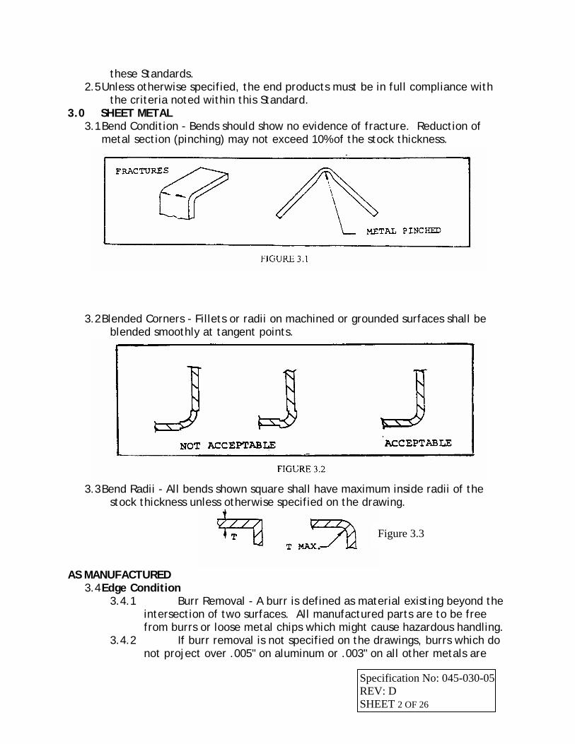
3.1 Bend Condition - Bends should show no evidence of fracture. Reduction of metal section (pinching) may not exceed 10% of the stock thickness.
3.2 Blended Corners - Fillets or radii on machined or grounded surfaces shall be blended smoothly at tangent points.
3.3 Bend Radii - All bends shown square shall have maximum inside radii of the
stock thickness unless otherwise specified on the drawing.
Figure 3.3
AS MANUFACTURED 3.4 Edge Condition
3.4.1 Burr Removal - A burr is defined as material existing beyond the intersection of two surfaces. All manufactured parts are to be free from burrs or loose metal chips which might cause hazardous handling.
3.4.2 If burr removal is not specified on the drawings, burrs which do not project over .005" on aluminum or .003" on all other metals are
Specification No: 045-030-05 REV: D SHEET 2 OF 26
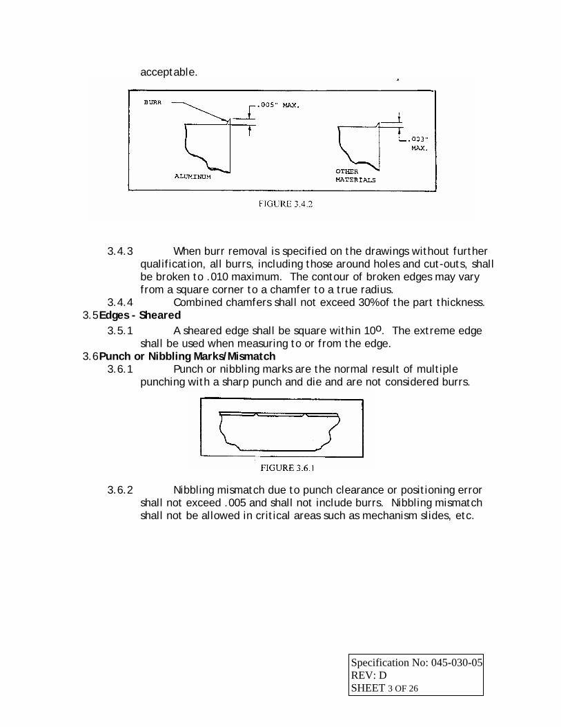
acceptable.
3.4.3 When burr removal is specified on the drawings without further qualification, all burrs, including those around holes and cut-outs, shall be broken to .010 maximum. The contour of broken edges may vary from a square corner to a chamfer to a true radius.
3.4.4 Combined chamfers shall not exceed 30% of the part thickness. 3.5 Edges - Sheared
3.5.1 A sheared edge shall be square within 10o. The extreme edge shall be used when measuring to or from the edge.
3.6 Punch or Nibbling Marks/Mismatch 3.6.1 Punch or nibbling marks are the normal result of multiple
punching with a sharp punch and die and are not considered burrs.
3.6.2 Nibbling mismatch due to punch clearance or positioning error shall not exceed .005 and shall not include burrs. Nibbling mismatch shall not be allowed in critical areas such as mechanism slides, etc.
Specification No: 045-030-05 REV: D SHEET 3 OF 26
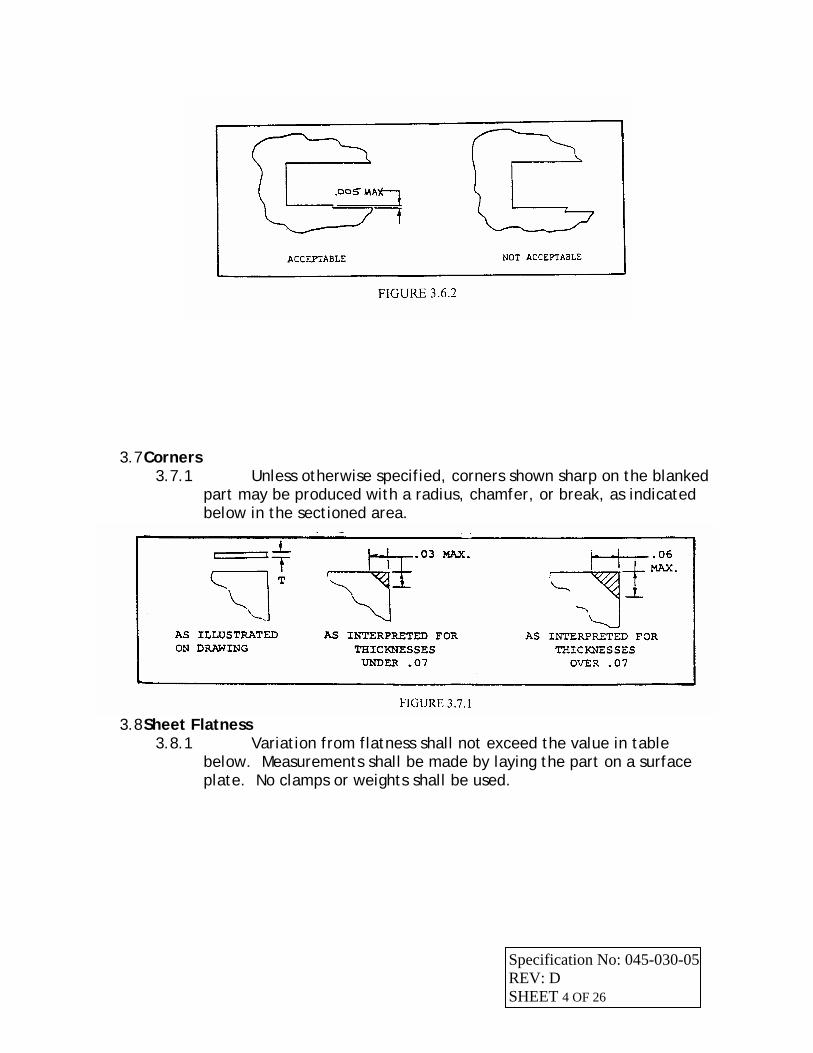
3.7 Corners 3.7.1 Unless otherwise specified, corners shown sharp on the blanked
part may be produced with a radius, chamfer, or break, as indicated below in the sectioned area.
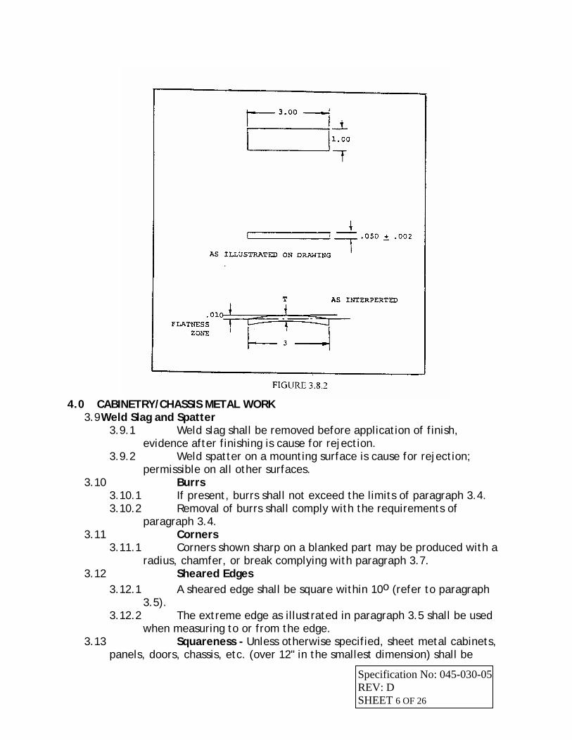
3.8 Sheet Flatness
3.8.1 Variation from flatness shall not exceed the value in table below. Measurements shall be made by laying the part on a surface plate. No clamps or weights shall be used.
Specification No: 045-030-05 REV: D SHEET 4 OF 26
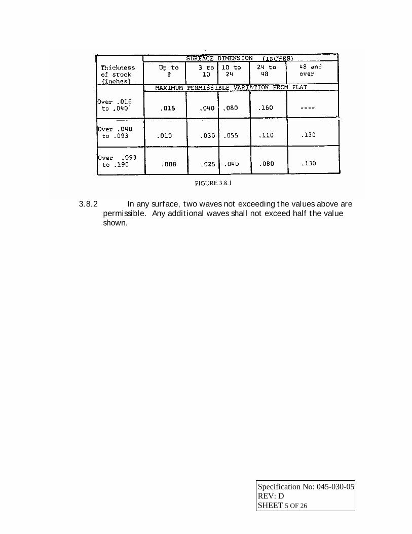
3.8.2 In any surface, two waves not exceeding the values above are
permissible. Any additional waves shall not exceed half the value shown.
Specification No: 045-030-05 REV: D SHEET 5 OF 26
4.0 CABINETRY/CHASSIS METAL WORK
3.9 Weld Slag and Spatter 3.9.1 Weld slag shall be removed before application of finish,
evidence after finishing is cause for rejection. 3.9.2 Weld spatter on a mounting surface is cause for rejection;
permissible on all other surfaces. 3.10 Burrs
3.10.1 If present, burrs shall not exceed the limits of paragraph 3.4. 3.10.2 Removal of burrs shall comply with the requirements of
paragraph 3.4. 3.11 Corners
3.11.1 Corners shown sharp on a blanked part may be produced with a radius, chamfer, or break complying with paragraph 3.7.
3.12 Sheared Edges 3.12.1 A sheared edge shall be square within 10o (refer to paragraph
3.5). 3.12.2 The extreme edge as illustrated in paragraph 3.5 shall be used
when measuring to or from the edge. 3.13 Squareness - Unless otherwise specified, sheet metal cabinets,
panels, doors, chassis, etc. (over 12" in the smallest dimension) shall be
Specification No: 045-030-05 REV: D SHEET 6 OF 26
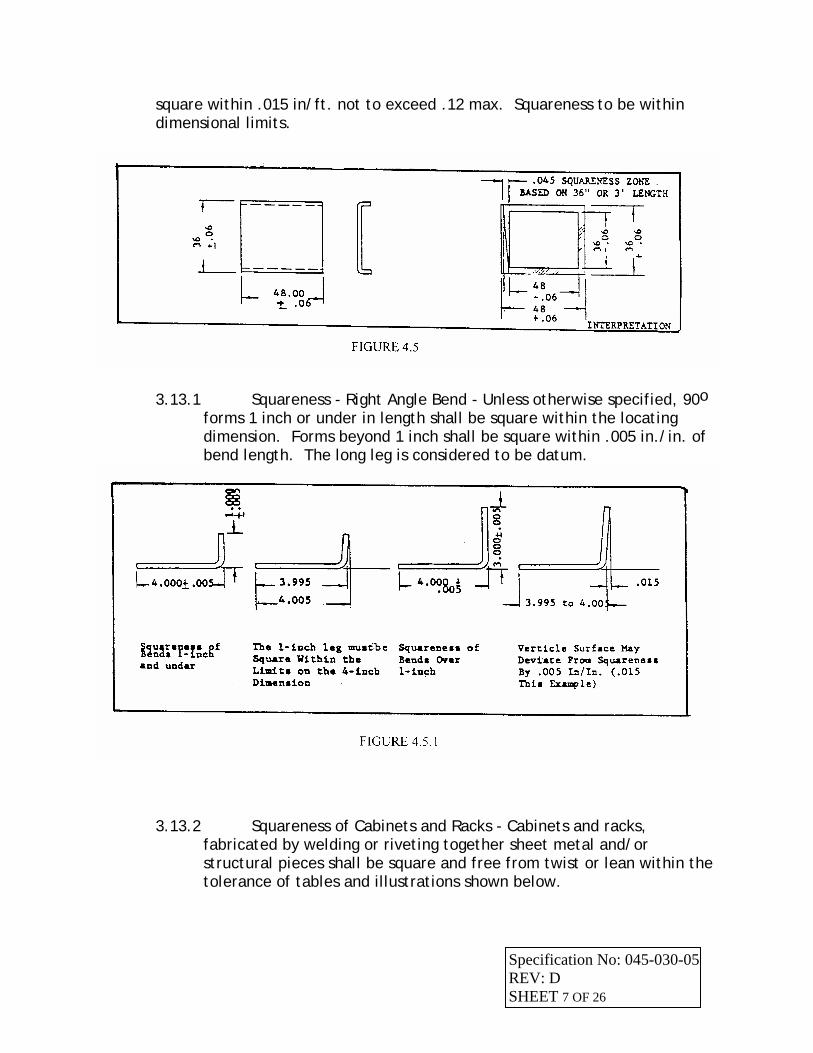
square within .015 in/ft. not to exceed .12 max. Squareness to be within dimensional limits.
3.13.1 Squareness - Right Angle Bend - Unless otherwise specified, 90o forms 1 inch or under in length shall be square within the locating dimension. Forms beyond 1 inch shall be square within .005 in./in. of bend length. The long leg is considered to be datum.
3.13.2 Squareness of Cabinets and Racks - Cabinets and racks, fabricated by welding or riveting together sheet metal and/or structural pieces shall be square and free from twist or lean within the tolerance of tables and illustrations shown below.
Specification No: 045-030-05 REV: D SHEET 7 OF 26
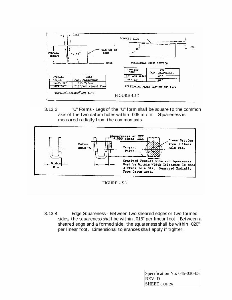
3.13.3 "U" Forms - Legs of the "U" form shall be square to the common
axis of the two datum holes within .005 in./in. Squareness is measured radially from the common axis.
3.13.4 Edge Squareness - Between two sheared edges or two formed sides, the squareness shall be within .015" per linear foot. Between a sheared edge and a formed side, the squareness shall be within .020" per linear foot. Dimensional tolerances shall apply if tighter.
Specification No: 045-030-05 REV: D SHEET 8 OF 26
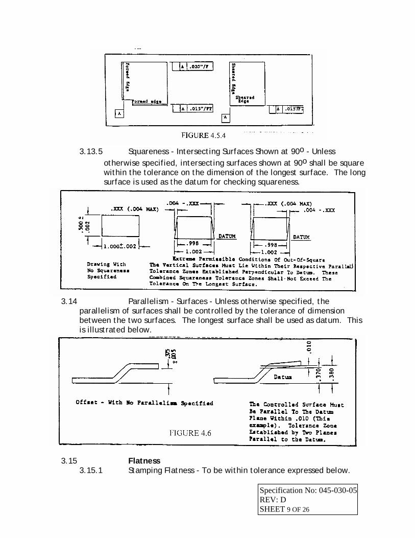
3.13.5 Squareness - Intersecting Surfaces Shown at 90o - Unless
otherwise specified, intersecting surfaces shown at 90o shall be square within the tolerance on the dimension of the longest surface. The long surface is used as the datum for checking squareness.
3.14 Parallelism - Surfaces - Unless otherwise specified, the
parallelism of surfaces shall be controlled by the tolerance of dimension between the two surfaces. The longest surface shall be used as datum. This is illustrated below.
3.15 Flatness 3.15.1 Stamping Flatness - To be within tolerance expressed below.
Specification No: 045-030-05 REV: D SHEET 9 OF 26
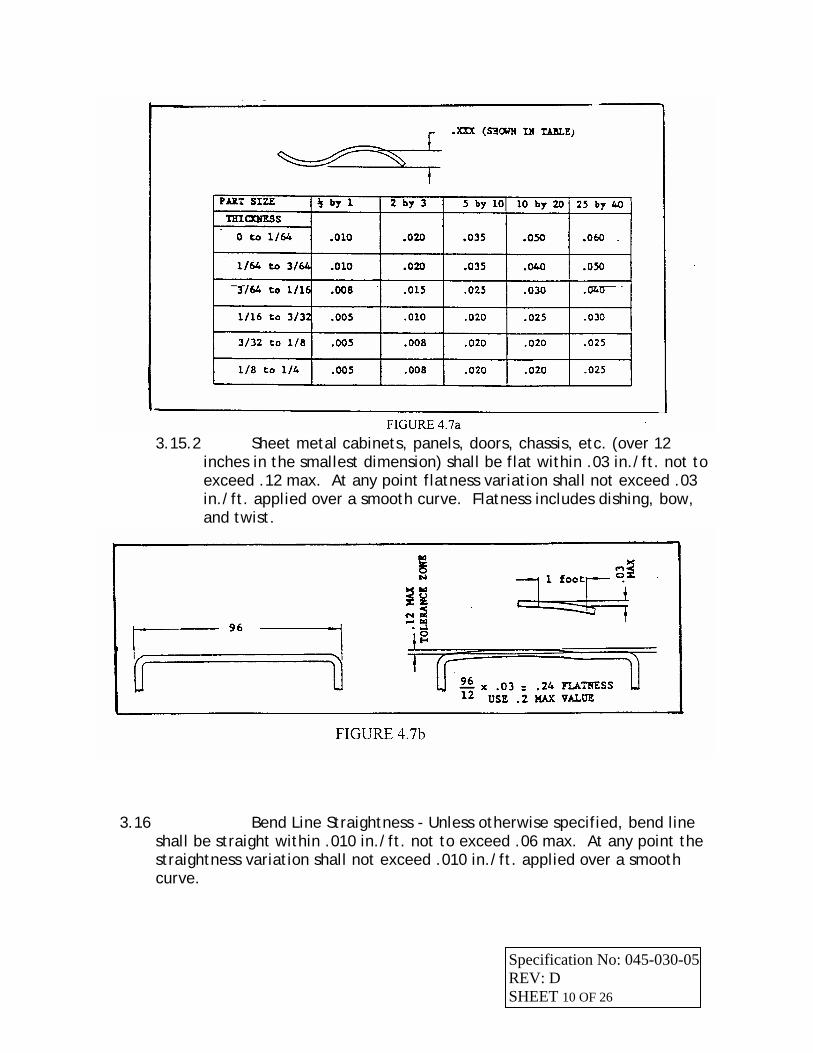
3.15.2 Sheet metal cabinets, panels, doors, chassis, etc. (over 12
inches in the smallest dimension) shall be flat within .03 in./ft. not to exceed .12 max. At any point flatness variation shall not exceed .03 in./ft. applied over a smooth curve. Flatness includes dishing, bow, and twist.
3.16 Bend Line Straightness - Unless otherwise specified, bend line shall be straight within .010 in./ft. not to exceed .06 max. At any point the straightness variation shall not exceed .010 in./ft. applied over a smooth curve.
Specification No: 045-030-05 REV: D SHEET 10 OF 26
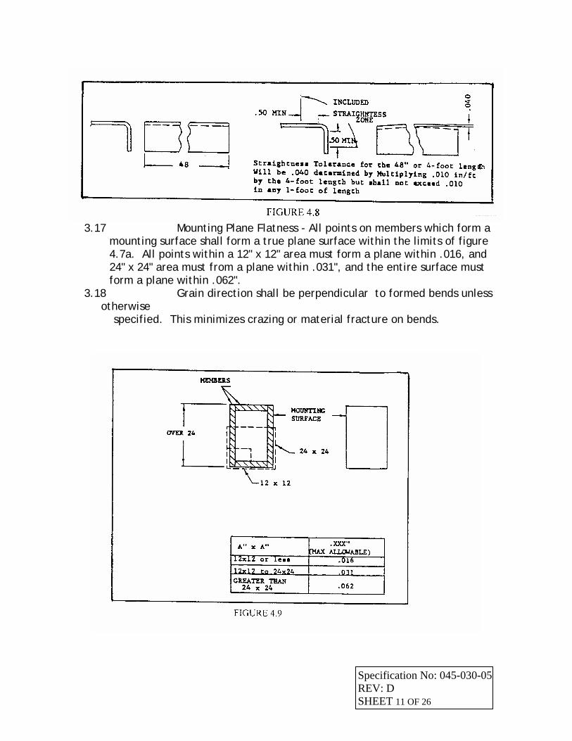
3.17 Mounting Plane Flatness - All points on members which form a
mounting surface shall form a true plane surface within the limits of figure 4.7a. All points within a 12" x 12" area must form a plane within .016, and 24" x 24" area must from a plane within .031", and the entire surface must form a plane within .062".
3.18 Grain direction shall be perpendicular to formed bends unless otherwise
specified. This minimizes crazing or material fracture on bends.
Specification No: 045-030-05 REV: D SHEET 11 OF 26
4.10 COMPONENT ASSEMBLY 4.10.1 General - Cardcages, doors, panels, sideplates, electro-mechanical subassemblies, cabling and hinge/latch/locking mechanisms shall conform to the requirements specified herein or as required by referenced paragraph. 4.10.2 Damage - There shall be no damage beyond the limits specified in applicable sections of this document.
4.11 Installation 4.11.1 External Doors
4.11.1.1 Vertical requirements shall be cause for rejection. 4.12 Hardware Assembly Sequence
4.12.1 Acceptable - The sequence of mechanical hardware assembly conforms to specific product documentation. . See 045-030-05 Section 5.2.2
4.12.2 Unacceptable - Any deviation from product documentation. 4.13 Overall Requirements of Cabinets and Enclosures
4.13.1 Cabinets - Installation is not above or below frame top surface by more than 0.125"; not out of parallel with frame (there shall not be more than 0.150" difference between top and bottom dimension measured; measured from edge of frame to edge of door at extreme top and bottom).
4.13.2 Low Profile Cabinet - Installation is not out of parallel by more than 0.125" (measured gap between door and frame at hinged side; compare to gap dimension at opposite side).
4.13.3 Foam Tape (non-FCC compliant system) is applied in parallel with mounting surfaces; ends are cut square, with no gaps or overlaps between sections.
4.13.4 EMI gasketing (FCC compliant system) is installed in accordance with applicable engineering drawing requirement, and no discernible damage is evident. Sections of gasketing can not have less than three (3) mounting anchors to be acceptable.
4.13.5 Doors hinge smoothly throughout open/closure travel; close or latch positively. For FCC compliant cabinets, EMI gasketing (either wire mesh or carbon filled) must make intimate contact with cabinet; this is measured by inserting dollar bill between door and cabinet; lock door; gently pull the dollar out. A resistance must be felt, if none is felt, door/latch mechanism must be adjusted.
4.14 Sideplates 4.14.1 (Vertical Cabinets) - Installation is not above or below frame top surface
by more than 0.100"; not out of parallel with frame (there shall not be more than 0.125" difference between top and bottom dimension measured; measure from edge of frame to edge of sideplates at extreme top and bottom).
4.14.2 (Low Profile Cabinets) - Installation is not out of parallel by more than 0.100" (measure gap between door and frame at hinged side; compare to gap dimension at opposite side).
Specification No: 045-030-05 4.14.3 Foam Tape (non-FCC compliant system) is applied in parallel with
REV: D SHEET 12 OF 26
mounting surfaces; ends are cut square, with no gaps overlaps between sections.
4.14.4 EMI gasketing (FCC compliant system) is installed in accordance with applicable engineering drawing requirement, and no discernible damage is evident. Sections must have at least three (3) mounting anchors to be acceptable.
4.14.5 For FCC compliant cabinets, EMI gasketing (either wire mesh or carbon filled) must make intimate contact with cabinet; this is measured by inserting a dollar bill between sideplate and cabinet; gently pull the dollar out. A resistance must be felt; if none is felt, adjustments must be made.
5.0 MECHANICAL FASTENERS 5.1 General - Mechanical parts shall be assembled in accordance with the
requirements described herein unless otherwise specified in the applicable product documentation.
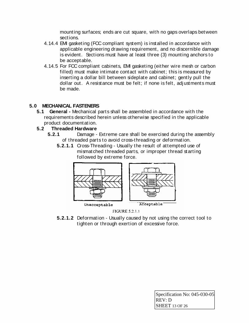
5.2 Threaded Hardware 5.2.1 Damage - Extreme care shall be exercised during the assembly
of threaded parts to avoid cross-threading or deformation. 5.2.1.1 Cross-Threading - Usually the result of attempted use of
mismatched threaded parts, or improper thread starting followed by extreme force.
5.2.1.2 Deformation - Usually caused by not using the correct tool to
tighten or through exertion of excessive force.
Specification No: 045-030-05 REV: D SHEET 13 OF 26
5.2.2 Assembly Sequence - General Application (See 045-030-04
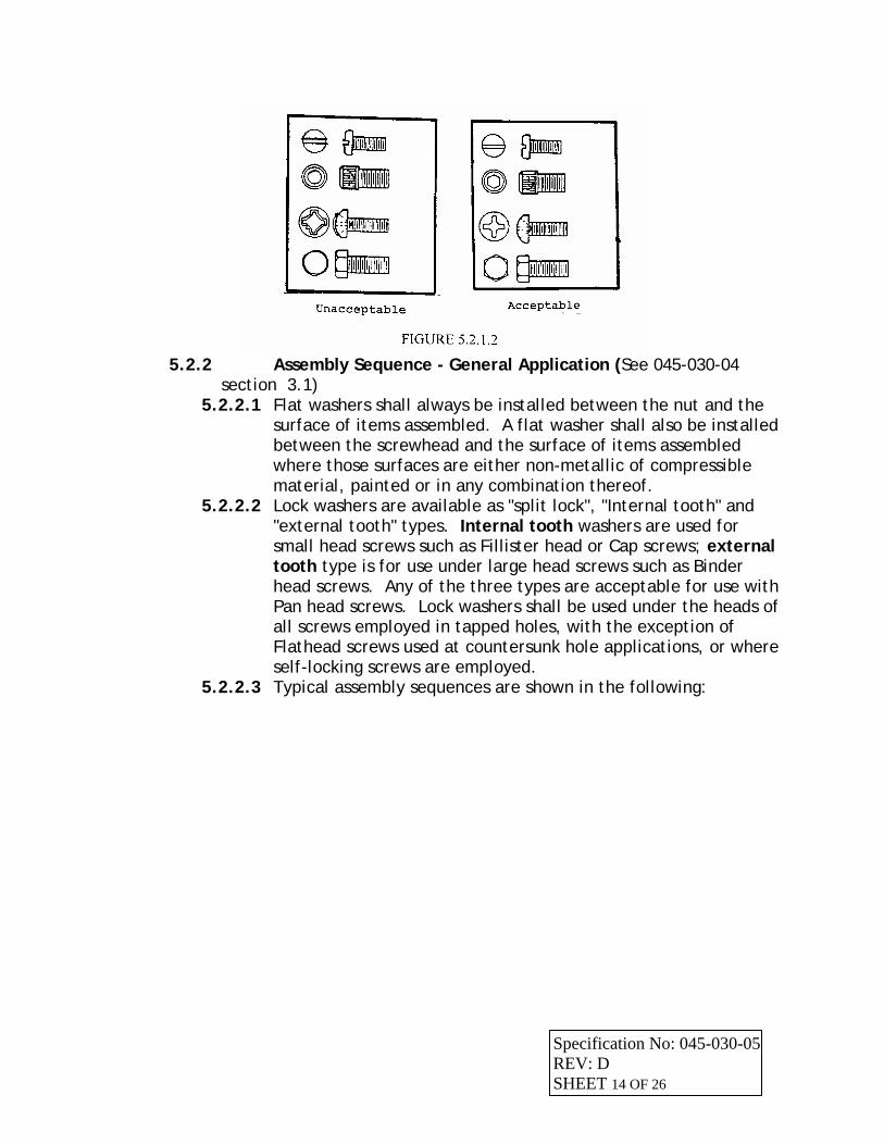
section 3.1) 5.2.2.1 Flat washers shall always be installed between the nut and the
surface of items assembled. A flat washer shall also be installed between the screwhead and the surface of items assembled where those surfaces are either non-metallic of compressible material, painted or in any combination thereof.
5.2.2.2 Lock washers are available as "split lock", "Internal tooth" and "external tooth" types. Internal tooth washers are used for small head screws such as Fillister head or Cap screws; external tooth type is for use under large head screws such as Binder head screws. Any of the three types are acceptable for use with Pan head screws. Lock washers shall be used under the heads of all screws employed in tapped holes, with the exception of Flathead screws used at countersunk hole applications, or where self-locking screws are employed.
5.2.2.3 Typical assembly sequences are shown in the following:
Specification No: 045-030-05 REV: D SHEET 14 OF 26

5.2.3 Assembly Sequence - Special Application 5.2.3.1 Enlarged or Elongated Hole
5.2.3.2 Dissimilar Metals
Specification No: 045-030-05 REV: D SHEET 15 OF 26
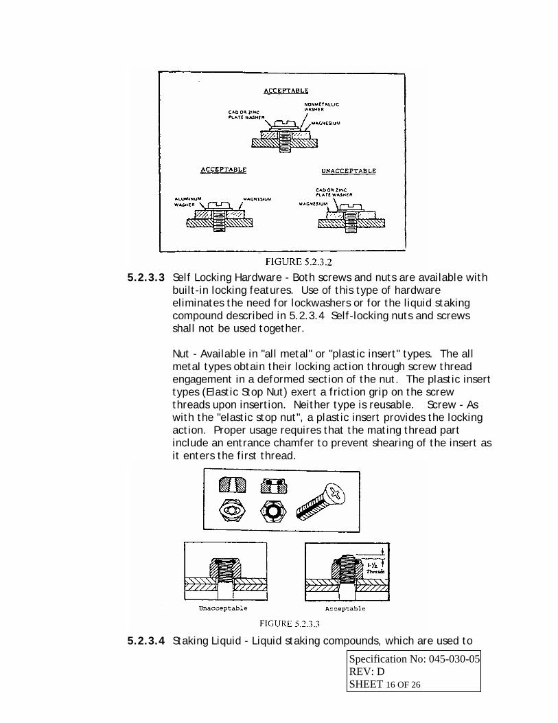
5.2.3.3 Self Locking Hardware - Both screws and nuts are available with
built-in locking features. Use of this type of hardware eliminates the need for lockwashers or for the liquid staking compound described in 5.2.3.4 Self-locking nuts and screws shall not be used together. Nut - Available in "all metal" or "plastic insert" types. The all metal types obtain their locking action through screw thread engagement in a deformed section of the nut. The plastic insert types (Elastic Stop Nut) exert a friction grip on the screw threads upon insertion. Neither type is reusable. Screw - As with the "elastic stop nut", a plastic insert provides the locking action. Proper usage requires that the mating thread part include an entrance chamfer to prevent shearing of the insert as it enters the first thread.
5.2.3.4 Staking Liquid - Liquid staking compounds, which are used to
Specification No: 045-030-05 REV: D SHEET 16 OF 26
ensure mechanical fastener reliability, shall be employed only when use of mechanical locking devices, such as lockwashers, self-locking nuts, or screws, is not practical. This staking compound, which is commonly referred to by its "brand name" (Loctite) is available in several types.
5.2.3.4.1 Type Selection - Per applicable product documentation. 5.2.3.4.2 Procedure - Zinc and cadmium plated
material and oily or greasy surfaces, shall be cleaned and thoroughly dry before application of staking material. Apply the liquid to the mechanical fastener's threads; mate the fasteners, tightening to the required degree. Excess staking material shall be wiped away.
NOTE: Any previous application of staking compound must be removed prior to re-applying whenever it is necessary to disassemble and reassemble the mated mechanical fasteners.
5.2.4 Thread Protrusion 5.2.4.1 Screws shall extend beyond nut or threaded surface by a
minimum of 1 1/2 threads unless otherwise specified in applicable drawing.
5.2.4.2 Screws entering blind holes shall engage threads for a minimum depth equivalent to 1 1/2 times the screw diameter. This shall apply to self-tapping screws or screws entering tapped holes.
Specification No: 045-030-05 REV: D SHEET 17 OF 26
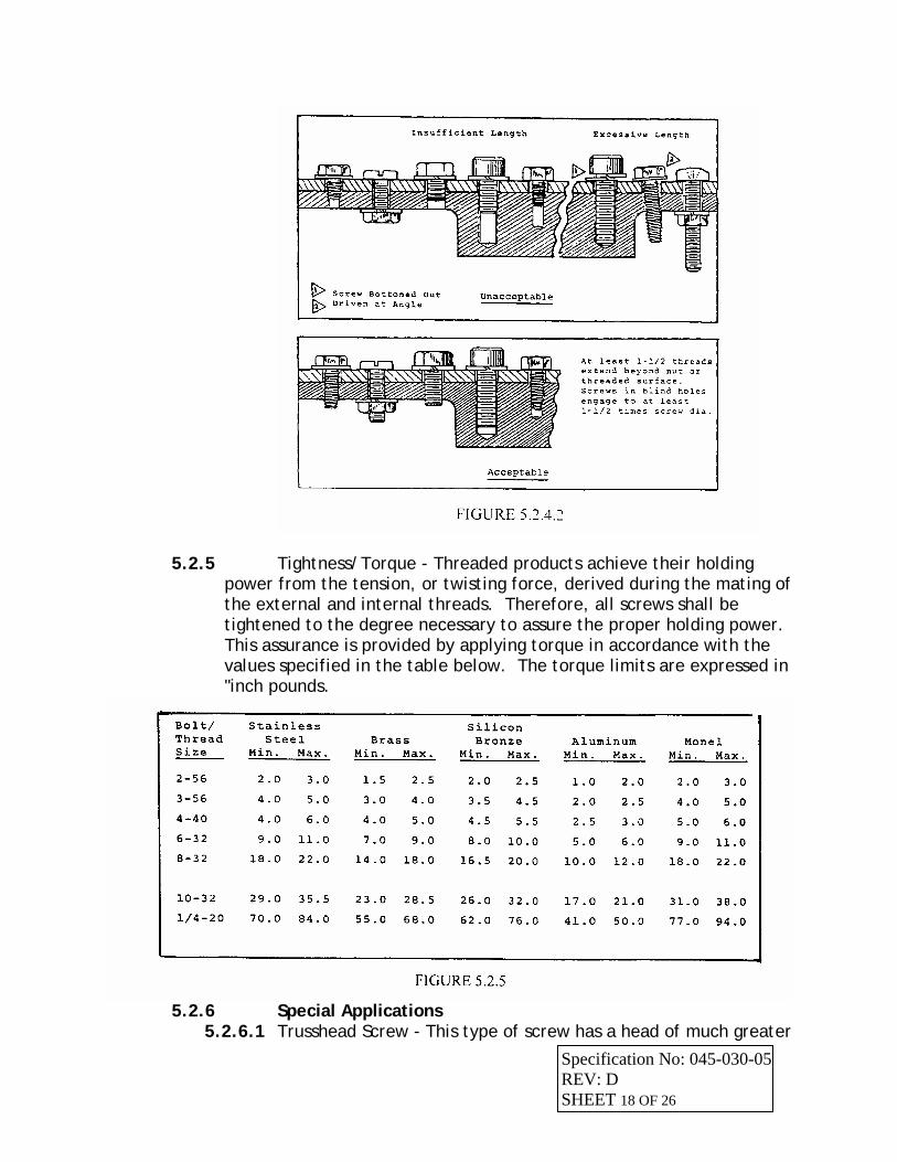
5.2.5 Tightness/Torque - Threaded products achieve their holding power from the tension, or twisting force, derived during the mating of the external and internal threads. Therefore, all screws shall be tightened to the degree necessary to assure the proper holding power. This assurance is provided by applying torque in accordance with the values specified in the table below. The torque limits are expressed in "inch pounds.
5.2.6 Special Applications
Specification No: 045-030-05 5.2.6.1 Trusshead Screw - This type of screw has a head of much greater
REV: D SHEET 18 OF 26
diameter than standard hardware of the same size, making it ideally suited for use in elongated holes. Unless installed through a painted surface, trusshead screws will not require use of a flat washer under the head.
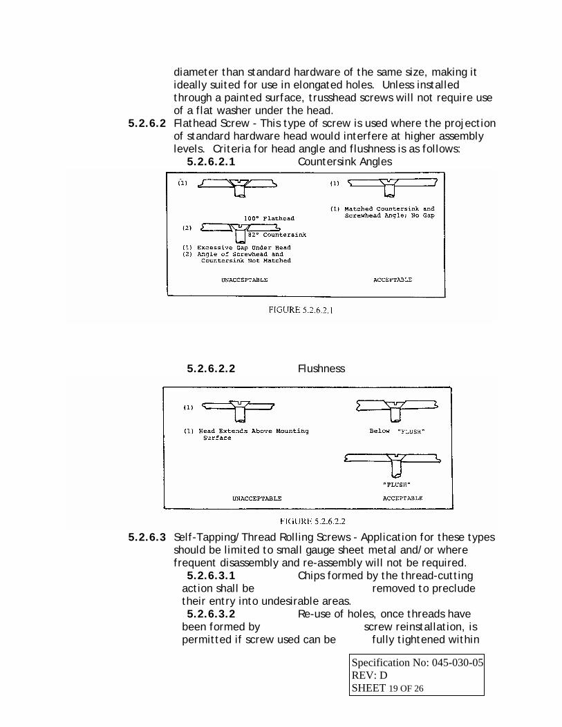
5.2.6.2 Flathead Screw - This type of screw is used where the projection of standard hardware head would interfere at higher assembly levels. Criteria for head angle and flushness is as follows:
5.2.6.2.1 Countersink Angles
5.2.6.2.2 Flushness
5.2.6.3 Self-Tapping/Thread Rolling Screws - Application for these types
should be limited to small gauge sheet metal and/or where frequent disassembly and re-assembly will not be required.
5.2.6.3.1 Chips formed by the thread-cutting action shall be removed to preclude their entry into undesirable areas. 5.2.6.3.2 Re-use of holes, once threads have
been formed by screw reinstallation, is permitted if screw used can be fully tightened within
Specification No: 045-030-05 REV: D SHEET 19 OF 26
specification.
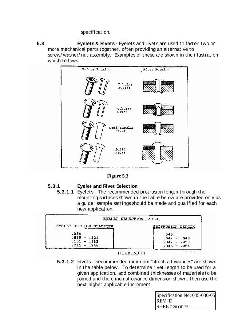
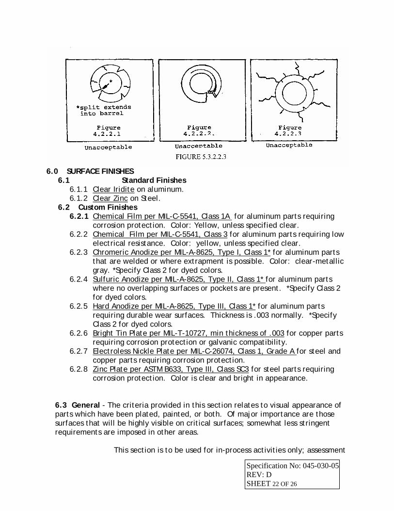
5.3 Eyelets & Rivets - Eyelets and rivets are used to fasten two or more mechanical parts together, often providing an alternative to screw/washer/nut assembly. Examples of these are shown in the illustration which follows:
5.3.1 Eyelet and Rivet Selection
Figure 5.3
5.3.1.1 Eyelets - The recommended protrusion length through the mounting surfaces shown in the table below are provided only as a guide; sample settings should be made and qualified for each new application.
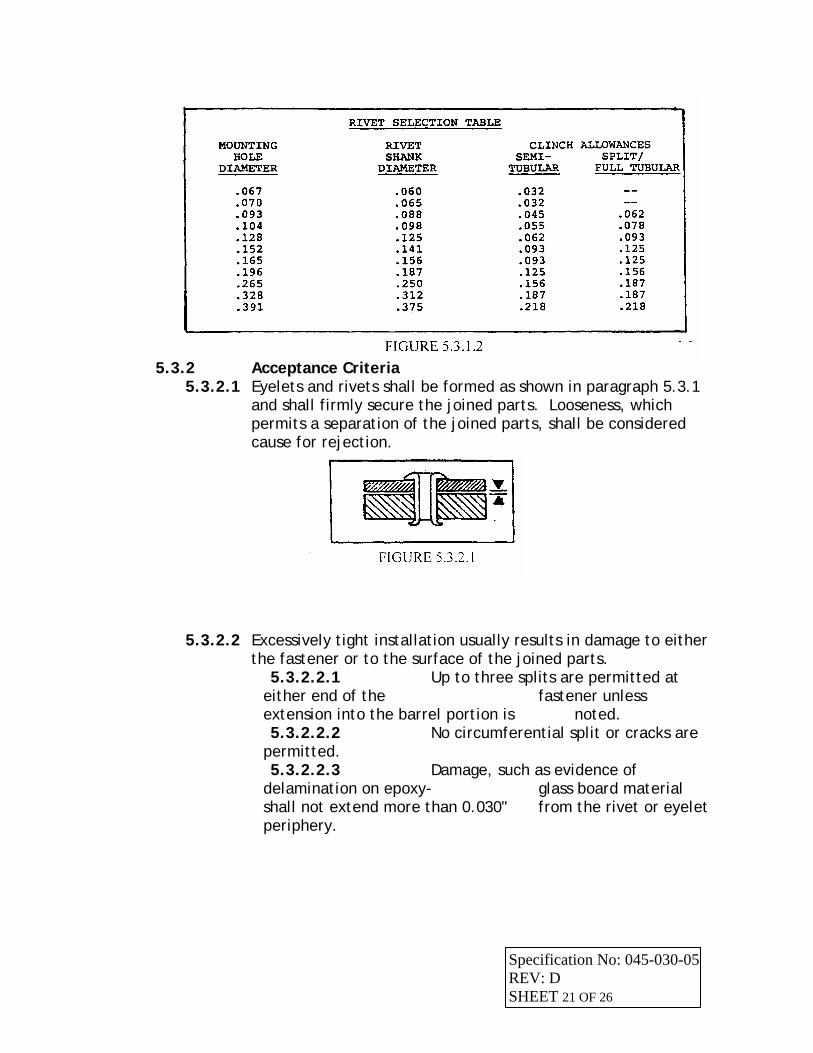
5.3.1.2 Rivets - Recommended minimum "clinch allowances" are shown
in the table below. To determine rivet length to be used for a given application, add combined thicknesses of materials to be joined and the clinch allowance dimension shown, then use the next higher applicable increment.
Specification No: 045-030-05 REV: D SHEET 20 OF 26
5.3.2 Acceptance Criteria
5.3.2.1 Eyelets and rivets shall be formed as shown in paragraph 5.3.1 and shall firmly secure the joined parts. Looseness, which permits a separation of the joined parts, shall be considered cause for rejection.
5.3.2.2 Excessively tight installation usually results in damage to either the fastener or to the surface of the joined parts.
5.3.2.2.1 Up to three splits are permitted at either end of the fastener unless extension into the barrel portion is noted. 5.3.2.2.2 No circumferential split or cracks are
permitted. 5.3.2.2.3 Damage, such as evidence of
delamination on epoxy- glass board material shall not extend more than 0.030" from the rivet or eyelet periphery.
Specification No: 045-030-05 REV: D SHEET 21 OF 26
6.0 SURFACE FINISHES
6.1 Standard Finishes 6.1.1 Clear Iridite on aluminum. 6.1.2 Clear Zinc on Steel.
6.2 Custom Finishes 6.2.1 Chemical Film per MIL-C-5541, Class 1A for aluminum parts requiring
corrosion protection. Color: Yellow, unless specified clear. 6.2.2 Chemical Film per MIL-C-5541, Class 3 for aluminum parts requiring low
electrical resistance. Color: yellow, unless specified clear. 6.2.3 Chromeric Anodize per MIL-A-8625, Type I, Class 1* for aluminum parts
that are welded or where extrapment is possible. Color: clear-metallic gray. *Specify Class 2 for dyed colors.
6.2.4 Sulfuric Anodize per MIL-A-8625, Type II, Class 1* for aluminum parts where no overlapping surfaces or pockets are present. *Specify Class 2 for dyed colors.
6.2.5 Hard Anodize per MIL-A-8625, Type III, Class 1* for aluminum parts requiring durable wear surfaces. Thickness is .003 normally. *Specify Class 2 for dyed colors.
6.2.6 Bright Tin Plate per MIL-T-10727, min thickness of .003 for copper parts requiring corrosion protection or galvanic compatibility.
6.2.7 Electroless Nickle Plate per MIL-C-26074, Class 1, Grade A for steel and copper parts requiring corrosion protection.
6.2.8 Zinc Plate per ASTM B633, Type III, Class SC3 for steel parts requiring corrosion protection. Color is clear and bright in appearance.
6.3 General - The criteria provided in this section relates to visual appearance of parts which have been plated, painted, or both. Of major importance are those surfaces that will be highly visible on critical surfaces; somewhat less stringent requirements are imposed in other areas. This section is to be used for in-process activities only; assessment
Specification No: 045-030-05 REV: D SHEET 22 OF 26
of received materials shall be performed using appropriate Procurement specifications, and/or detailed Incoming Inspection criteria and techniques.
Major Defect The type of defect that: • Is clearly visible in an un-highlighted condition • Exposes bare metals or substrate surface • Exceeds stated criteria or other specific requirements • Is easily felt with a fingernail (dents or scratches) • Would leave a greater flaw if removed or reworked (inclusion) • Is non-uniform surface finish (shaded appearance) • Would cause corrosion, rust, peeling, delamination, etc.
Minor defect The type of defect that:
• Is clearly not visible in an un-highlighted condition or when assembled in an
assembly • Barely felt with a fingernail • Tends to fade out or blend in with surrounding surface • Would be concealed during next process or assembly level (label, paint
or other finishing process)
Normal Viewing Plane The normal viewing plane is defined as the view obtained when observing the assembled unit top, front, sides, and back exterior surfaces in a plane perpendicular to these surfaces. The part will not be rotated except to eliminate any glare from surrounding light that tends to produce a “highlighted” condition.
Light condition 75 – 90 foot candles
Viewing distance These are appropriate based on the part in an installed position.
Surface Class A: 18 inches Surface Class B: 36 inches Surface Class C: in excess of 36 inches not to exceed 72 inches
Viewing Time All surfaces 10 seconds maximum Personnel vision 20/20 vision
6.4 Surface Classification - Surfaces are grouped into three
categories for inspection purposes:
Specification No: 045-030-05 REV: D SHEET 23 OF 26
Specification No: 045-030-05
Class A User's Primary Product Exterior: Doors, chassis skins, cabinet
tops, rack mount flanges, control panels, exposed areas of cabinet frames; Any surface that is normally and immediately visible to the customer or end user while the product is being used in its normal operating condition and visible to the user without opening service doors. On card cages the Class A surface will be flanges and the number strip edge of the card guide rail.
These surfaces will be free of all major defects and reasonably free of any minor defects. Defects on these surfaces are likely to be seen and associated with a perceived reduction in the overall quality or appearance of the product. Note: Slight imperfections characteristic of individual process capabilities may be visible on Class A surfaces. Acceptance of these slight imperfections shall be judged according to applicable Hybricon or customer specifications and standards.
Class B User Access Interior: Chassis skins, cabinet and enclosure tops, internal control panels, interior side of enclosure and card cages, power distribution, front panels, interior items with user information / silk-screening; areas which are visible when the user access doors are open. Expected to appear consistent, of good integrity, and with limited appearance of flaws.
These surfaces may have some minor defects but will be free of all major defects. Minor defects on these surfaces are not likely to be seen or viewed as a perceived reduction in the overall quality or appearance of this product. Any surface that can be seen from the front (but not the front surface of the unit) with the unit and/or cover plate removed. Any surface that is visible from the rear after installation, or the rear surface of the individual removable option card. For example, rear panels, side panels, top and bottom surfaces are commonly Class B surfaces
Class C Structural Interior: Areas not visible without disassembly.
Coatings are for corrosion protection only.
REV: D SHEET 24 OF 26
Class C surfaces may have any or all minor defects and some major defects. These major defects may be subject to review by the MRB Board.
Defects on these surfaces, if seen by the customer, are not likely to be regarded as detracting from the overall cosmetic or functional quality of the product.
Interior surfaces, or areas to be covered by labels or other panels are examples of “C” surfaces.
PROCEDURE All drawings will incorporate cosmetic surface requirements as specified below. Designations All part surfaces will be designated as one of three classes (A,B, or C) according to location and importance in a completely assembled product or system.
6.4Acceptance Criteria - Three acceptance designations are used in the following table to describe the criteria.
None Allowed - No occurrences of the attribute are permissible. Items with this designation are typically functional in nature, and will result in product degradation. These attributes are not subject to the cursory inspection described below.
Not Apparent - Attribute is not discernible in the final application of the
part. Attributes with this designation are aesthetic in nature. Visual inspection for aesthetics is to be conducted in a manner which best duplicates the end use of the part. The preferred viewing angle and distance being that which would exist if the part was installed in its final location, and the inspector is standing where the operator would stand while using or accessing the equipment. Minimum viewing distance should be three feet. The intention of the aesthetic inspection is to avoid usage of parts which detract from the appearance of the final product. Inspection time is limited to that which is necessary to scan (cursory inspection) all areas of the part.
Acceptable - Aesthetic in nature; will have no effect on the function of the
part and will not detract from the appearance of aesthetic viewpoint. Some flaws may have acceptable as well as not-acceptable attributes, e.g. a scratch which does not break the surface of the coating may be acceptable (depending on the class of surface), whereas if the coating is broken, there is a coverage void (Not Acceptable).
Specification No: 045-030-05 REV: D SHEET 25 OF 26
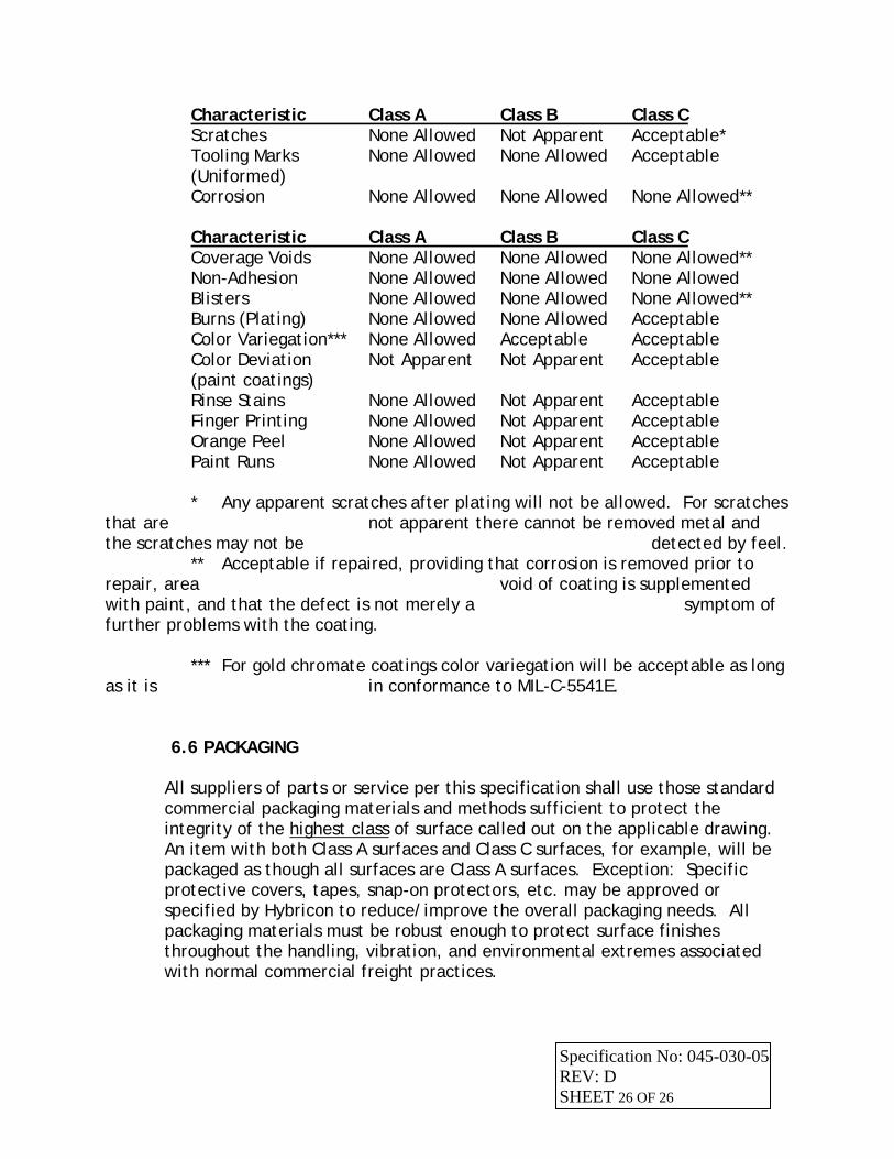
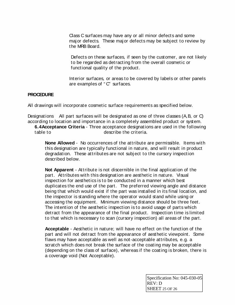
Characteristic Class A Class B Class C Scratches None Allowed Not Apparent Acceptable* Tooling Marks None Allowed None Allowed Acceptable (Uniformed) Corrosion None Allowed None Allowed None Allowed** Characteristic Class A Class B Class C Coverage Voids None Allowed None Allowed None Allowed** Non-Adhesion None Allowed None Allowed None Allowed Blisters None Allowed None Allowed None Allowed** Burns (Plating) None Allowed None Allowed Acceptable Color Variegation*** None Allowed Acceptable Acceptable Color Deviation Not Apparent Not Apparent Acceptable (paint coatings) Rinse Stains None Allowed Not Apparent Acceptable Finger Printing None Allowed Not Apparent Acceptable Orange Peel None Allowed Not Apparent Acceptable Paint Runs None Allowed Not Apparent Acceptable * Any apparent scratches after plating will not be allowed. For scratches that are not apparent there cannot be removed metal and the scratches may not be detected by feel. ** Acceptable if repaired, providing that corrosion is removed prior to repair, area void of coating is supplemented with paint, and that the defect is not merely a symptom of further problems with the coating. *** For gold chromate coatings color variegation will be acceptable as long as it is in conformance to MIL-C-5541E.
6.6 PACKAGING All suppliers of parts or service per this specification shall use those standard commercial packaging materials and methods sufficient to protect the integrity of the highest class of surface called out on the applicable drawing. An item with both Class A surfaces and Class C surfaces, for example, will be packaged as though all surfaces are Class A surfaces. Exception: Specific protective covers, tapes, snap-on protectors, etc. may be approved or specified by Hybricon to reduce/improve the overall packaging needs. All packaging materials must be robust enough to protect surface finishes throughout the handling, vibration, and environmental extremes associated with normal commercial freight practices.
Specification No: 045-030-05 REV: D SHEET 26 OF 26
When required, product designers and/or Prototek Engineering Department shall specify those materials or practices necessary to insure product protection.
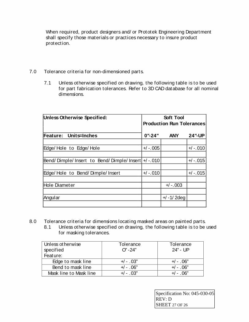
7.0 Tolerance criteria for non-dimensioned parts.
7.1 Unless otherwise specified on drawing, the following table is to be used for part fabrication tolerances. Refer to 3D CAD database for all nominal dimensions.
Unless Otherwise Specified: Soft Tool Production Run Tolerances Feature: Units=Inches 0"-24" ANY 24"-UP Edge/Hole to Edge/Hole +/-.005 +/-.010 Bend/Dimple/Insert to Bend/Dimple/Insert +/-.010 +/-.015 Edge/Hole to Bend/Dimple/Insert +/-.010 +/-.015 Hole Diameter +/-.003 Angular +/-1/2deg
8.0 Tolerance criteria for dimensions locating masked areas on painted parts. 8.1 Unless otherwise specified on drawing, the following table is to be used
for masking tolerances. Unless otherwise specified Feature:
Tolerance O”-24”
Tolerance 24”- UP
Edge to mask line +/- .03” +/- .06” Bend to mask line +/- .06” +/- .06”
Mask line to Mask line +/- .03” +/- .06”
Specification No: 045-030-05 REV: D SHEET 27 OF 26