workshop 7 parasolid solid example - fsb online · workshop 7 parasolid solid example. ws7-2...
TRANSCRIPT

WS7-1PAT301, Workshop 7, December 2005Copyright© 2005 MSC.Software Corporation
WORKSHOP 7PARASOLID SOLID EXAMPLE

WS7-2PAT301, Workshop 7, December 2005Copyright© 2005 MSC.Software Corporation

WS7-3PAT301, Workshop 7, December 2005Copyright© 2005 MSC.Software Corporation
Workshop ObjectivesLearn some of the steps that can be used to create a B-rep solid, i.e. extrude surface, shell, and edge blend. Then, createthe finite element model. Analyze the model, and postprocess the results from its analysis.
Problem DescriptionDisplay the deformed shape of the model using shaded render. Also, display the von Mises stress fringe.Tension fitting material: Aluminum with E = 10 x 106 psi and ν = 0.3Total load on tension fitting = 5000 lbf
Software VersionMSC.Patran 2005r2MSC.Nastran 2005r2b

WS7-4PAT301, Workshop 7, December 2005Copyright© 2005 MSC.Software Corporation
Key Concepts and Steps:Database: create a new database with Analysis Code = MSC.Nastran and Analysis Type = StructuralGeometry: create B-rep solid by extruding a created surface, then do various things like shell and edge blendElements: mesh the geometric solid with solid Tet10 elementsLoads/BCs: constrain the three holes at bottom of solid, and apply a Total Load to the large hole at the back of the fittingMaterials: specify an isotropic material for AluminumProperties: create a 3D solid propertyAnalysis: Solution Type = Nastran Linear Static, Solution Sequence = 101, Method = Full RunAnalysis: access analysis results by attaching the XDB file to databaseResults: plot model deformation and von Mises stress results

WS7-5PAT301, Workshop 7, December 2005Copyright© 2005 MSC.Software Corporation
Step 1. Create New Database for Tension Fitting
Create a new database called tension_fitting.db.
a. File / New.b. Enter tension_fitting as
the file name.c. Click OK.d. Choose Based on Model
for Tolerance.e. Choose MSC Nastran and
Structural for Analysis Code and Type.
f. Click OK.
a
b c
d
e
f

WS7-6PAT301, Workshop 7, December 2005Copyright© 2005 MSC.Software Corporation
Step 2. Create Surface
Create the Geometry for the tension fitting.
a. Geometry : Create / Surface / XYZ.
b. Enter <5 2 0>for Vector Coordinates List.
c. Enter [0 0 0] for Origin Coordinates List.
d. Click Apply.
a
b
cd
WS7-7PAT301, Workshop 7, December 2005Copyright© 2005 MSC.Software Corporation
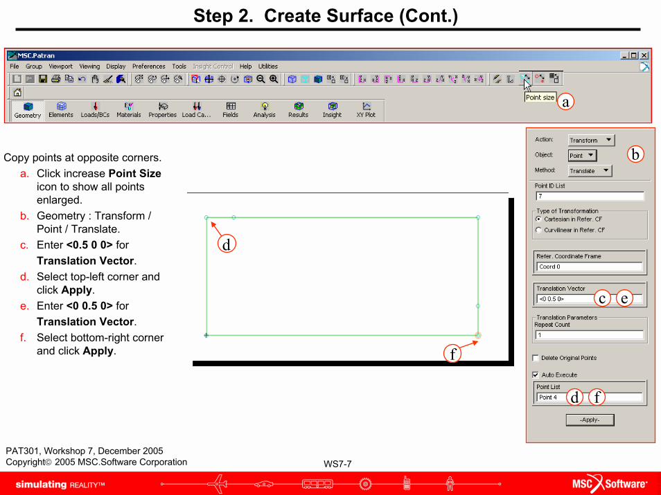
Step 2. Create Surface (Cont.)
Copy points at opposite corners. a. Click increase Point Size
icon to show all points enlarged.
b. Geometry : Transform / Point / Translate.
c. Enter <0.5 0 0> for Translation Vector.
d. Select top-left corner and click Apply.
e. Enter <0 0.5 0> for Translation Vector.
f. Select bottom-right corner and click Apply.
a
b
c e
d f
f
d
WS7-8PAT301, Workshop 7, December 2005Copyright© 2005 MSC.Software Corporation
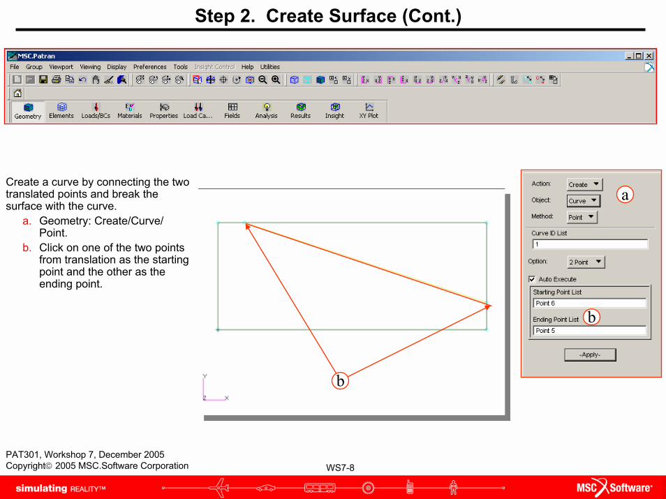
Step 2. Create Surface (Cont.)
Create a curve by connecting the two translated points and break the surface with the curve.
a. Geometry: Create/Curve/ Point.
b. Click on one of the two points from translation as the starting point and the other as the ending point.
a
b
b
WS7-9PAT301, Workshop 7, December 2005Copyright© 2005 MSC.Software Corporation
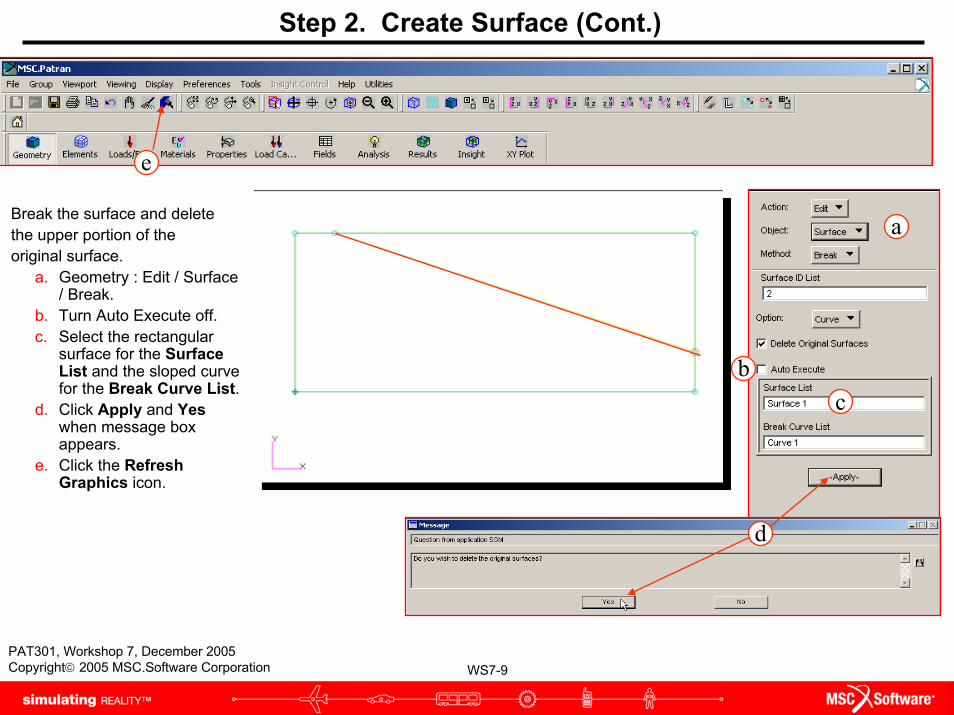
Step 2. Create Surface (Cont.)
Break the surface and deletethe upper portion of theoriginal surface.
a. Geometry : Edit / Surface / Break.
b. Turn Auto Execute off.c. Select the rectangular
surface for the Surface List and the sloped curve for the Break Curve List.
d. Click Apply and Yes when message box appears.
e. Click the Refresh Graphics icon.
a
c
e
b
d

WS7-10PAT301, Workshop 7, December 2005Copyright© 2005 MSC.Software Corporation
Step 2. Create Surface (Cont.)
Delete the upper surface (above the break curve).
a. Geometry : Delete / Surface.
b. Click on the triangular surface for the Surface List.
c. Click Apply.
a
b
c
WS7-11PAT301, Workshop 7, December 2005Copyright© 2005 MSC.Software Corporation
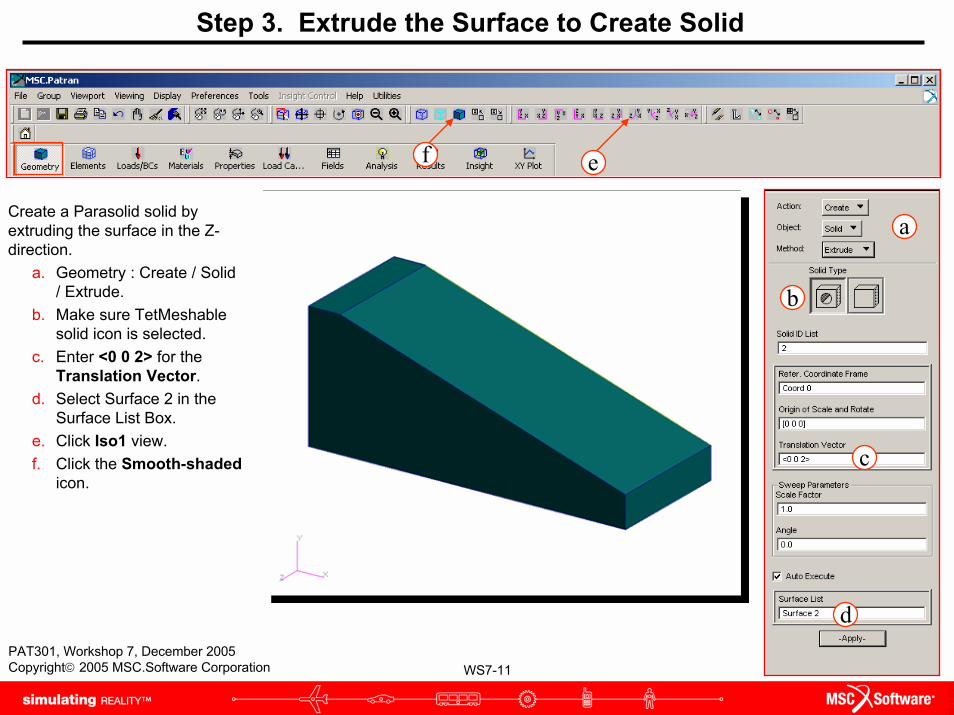
Create a Parasolid solid by extruding the surface in the Z-direction.
a. Geometry : Create / Solid / Extrude.
b. Make sure TetMeshablesolid icon is selected.
c. Enter <0 0 2> for the Translation Vector.
d. Select Surface 2 in the Surface List Box.
e. Click Iso1 view.f. Click the Smooth-shaded
icon.
Step 3. Extrude the Surface to Create Solid
a
b
c
d
ef
WS7-12PAT301, Workshop 7, December 2005Copyright© 2005 MSC.Software Corporation
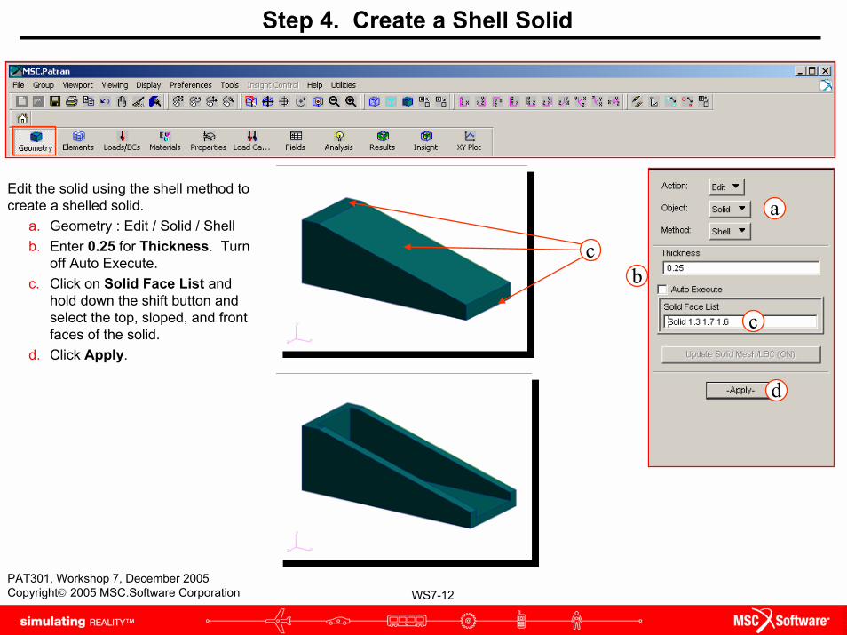
Step 4. Create a Shell Solid
Edit the solid using the shell method to create a shelled solid.
a. Geometry : Edit / Solid / Shellb. Enter 0.25 for Thickness. Turn
off Auto Execute.c. Click on Solid Face List and
hold down the shift button and select the top, sloped, and front faces of the solid.
d. Click Apply.
a
b
d
c
c

WS7-13PAT301, Workshop 7, December 2005Copyright© 2005 MSC.Software Corporation
Step 5. Create Fillets
Create the fillets on the inner edges of the solid.
a. Geometry : Edit / Solid /Edge Blend.
b. Make sure that the constantradius icon is selected.
c. Enter 0.25 for Constant Radius.
d. Make sure Edge(s) of Solidicon is selected.
e. Turn Auto Execute Off. f. Click on Solid Edge List and
use the shift-click technique and select the 5 edges on the inside of thesolid.
g. Click Apply. It may be necessary to rotate the object in order to see the inner edges more easily. This can be done by using the middle mouse button.
a
b
c
d
g
f
f
e

WS7-14PAT301, Workshop 7, December 2005Copyright© 2005 MSC.Software Corporation
Step 6. Create Holes for the Tension Fitting
Create the holes for the tension fitting bycreating primitive solids that pass through the solid, then subtracting them.
a. Geometry : Create / Solid /Primitive.
b. Select the cylinder icon.c. Enter 2.0 for the Height and
0.25 for the radius.d. Enter [-1 1.25 1] for the Base
Center Point List and Coord0.1 for the Axis List.
e. Click Apply.f. Geometry : Edit / Solid
/Boolean.g. Select Subtract icon.h. Select the tension fitting for the
Target Solid.i. Select the cylinder for the
Subtracting Solid List.
a
b
c
d
e
f
g
h
i

WS7-15PAT301, Workshop 7, December 2005Copyright© 2005 MSC.Software Corporation
Step 6. Create Holes for the Tension Fitting (Cont.)
Create the points where the threebottom holes will be placed by translating an existing point and, then translating again.
a. Click wireframe icon.b. Geometry : Transform /Point /
Translate.c. Enter <0 0 -0.5> for Translation
Vector.d. Select point at base edge of fillet.e. Applyf. Enter <-0.75 0 0> for Translation
Vector.g. Select translated point.h. Applyi. Enter <-1.50 0 0> for Translation
Vector. j. Enter 2 for repeat count.k. Select translated point.l. Apply
a
b
c
jg
k
d
de
WS7-16PAT301, Workshop 7, December 2005Copyright© 2005 MSC.Software Corporation
e
j
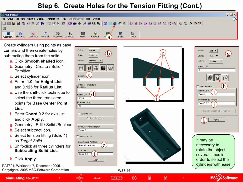
Step 6. Create Holes for the Tension Fitting (Cont.)
Create cylinders using points as base centers and then create holes by subtracting them from the solid.
a. Click Smooth shaded icon.b. Geometry : Create / Solid /
Primitive.c. Select cylinder icon.d. Enter -1.0 for Height List
and 0.125 for Radius List.e. Use the shift-click technique to
select the three translatedpoints for Base Center PointList.
f. Enter Coord 0.2 for axis listand click Apply.
g. Geometry : Edit / Solid /Boolean.h. Select subtract icon.i. Select tension fitting (Solid 1)
as Target Solid.j. Shift-click all three cylinders for
Subtracting Solid List.
k. Click Apply.
It may be necessary to rotate the object several times in order to select the cylinders with ease
b
c
d
ef
g
i
k
j
a
h

WS7-17PAT301, Workshop 7, December 2005Copyright© 2005 MSC.Software Corporation
Step 7. Create a Cylinder to Imprint Tension Fitting
Create a point in the center of thelarge hole in order to create thecylinder to imprint onto the solid.
a. Click wireframe icon.b. Geometry : Create / Point /
ArcCenter.c. Select the larger hole edge.d. Applye. Geometry : Create / Solid /
Primitive.f. Select cylinder icon.g. Enter 1.0 for Height List and
0.371 for Radius List.h. Click on point in the center of
the large hole.i. Enter Coord 0.1 for Axis List.j. Click Apply.k. Select Smooth Shaded icon.
a
c e
g
hi
j
k
hf
b
cd

WS7-18PAT301, Workshop 7, December 2005Copyright© 2005 MSC.Software Corporation
Step 8. Imprint the Solid
Use the cylinder to imprint the solid and then delete the cylinder, resulting in the finished solid.
a. Geometry : Edit / Solid / Imprint.
b. Select the tension fitting for the Solid List (A).
c. Select the cylinder for the Solid to Imprint List (B).
The solid may seem unchanged, but the imprint on the solid will not be visible until the cylinder has been deleted.
a
cb

WS7-19PAT301, Workshop 7, December 2005Copyright© 2005 MSC.Software Corporation
Step 9. Delete the Cylinder
Delete the cylinder and makesure imprint method wascompleted.
a. Geometry : Delete / Solidb. Select the cylinder for
Solid List.c. Click Apply.
a
bc
Edge added to solid.

WS7-20PAT301, Workshop 7, December 2005Copyright© 2005 MSC.Software Corporation
Step 10. TetMesh the Completed Solid
Create the TetMesh for the tension fitting.
a. Elements : Create /Mesh / Solid.
b. Make sure Tet,TetMesh, and Tet10are all selected.
c. Click on Input List andselect the solid.
d. Remove check for Automatic Calculationand enter 0.25 for Global Edge Length.
e. Click Apply.
a
b
c
d
e

WS7-21PAT301, Workshop 7, December 2005Copyright© 2005 MSC.Software Corporation
Step 11. Create Loads and Constraints
Create the loads and constraints for the model.
a. Click Smooth Shadedicon
b. Loads/BCs : Create / Total Load / Element Uniform.
c. Enter Force as the New Set Name.
d. Click Input Data…e. Enter <-5000 0 0> for the
Load and click OK.f. Click Select Application
Region…g. Select the vertical solid
face created by imprinting at the larger hole, then click Add.
h. Click OKi. Click Apply.
a
b
c
d
e
f
g
h
iIllustrated here is the desired application region. g

WS7-22PAT301, Workshop 7, December 2005Copyright© 2005 MSC.Software Corporation
Step 11. Create Loads and Constraints (Cont.)

WS7-23PAT301, Workshop 7, December 2005Copyright© 2005 MSC.Software Corporation
Step 11. Create Loads and Constraints (Cont.)
Create the constraints at the base holes.a. Loads/BCs : Create / Displacement /
Nodal.b. Enter Fixed as New Set Name.c. Click Input Data…d. Enter <0 0 0> for Translation
only, and click OK.e. Click Select Application Region.f. Click on Select Geometry Entities.g. Select Surface or Face iconh. Shift-click the cylindrical faces of
the three holes at the base, andClick Add.
i. Click OK.j. Click Apply.
a
b
c
d
e
fh
i
j hIllustrated here is the application region for
one of the three holes.
g

WS7-24PAT301, Workshop 7, December 2005Copyright© 2005 MSC.Software Corporation
Step 11. Create Loads and Constraints (Cont.)

WS7-25PAT301, Workshop 7, December 2005Copyright© 2005 MSC.Software Corporation
Step 12. Create Material Properties
Create the material properties for the model.
a. Materials : Create / Isotropic /Manual Input
b. Enter Aluminum for MaterialName.
c. Click Input Properties…d. Enter 10E6 for Elastic Modulus
and 0.3 for Poisson Ratio.e. Click OK f. Click Apply.
a
b
d
c
ef

WS7-26PAT301, Workshop 7, December 2005Copyright© 2005 MSC.Software Corporation
Step 13. Create 3D Element Properties
Create the 3D element properties for the tension fitting.
a. Properties : Create / 3D / Solid.
b. Enter 3D_tets for Property Set Name.
c. Click Input Properties…d. Click Mat Prop Name
icon. Select Aluminum from Select Material.
e. Click OKf. For Application Region,
select entire solid by dragging a box around it and click Add.
g. Click Apply.
a
b
c
e
f
g
d

WS7-27PAT301, Workshop 7, December 2005Copyright© 2005 MSC.Software Corporation
Step 14. Check the Load Case
Check the load case Default tomake sure that the load and constraintAre selected.
a. Load Cases : Modifyb. Click on the load case name
Default. c. Check to see that both the
load and constraints areassigned.
d. Click Cancel.
a
b
c
d

WS7-28PAT301, Workshop 7, December 2005Copyright© 2005 MSC.Software Corporation
Step 15. Run the Analysis
Run the Analysis with MSC.Nastran.a. Analysis : Analyze / Entire
Model / Full Run.b. Click Translation
Parameters...c. Make sure XDB and Print is
selected.d. Click OK.e. Click Solution Type…f. Make sure LINEAR STATIC
is selected.g. Click OK.h. Click Apply.
a
b
c
d
e
f
gh

WS7-29PAT301, Workshop 7, December 2005Copyright© 2005 MSC.Software Corporation
Step 16. Access the Results
Attach the XDB file and access the results.
a. Analysis : Access Results / Attach XDB / Result Entities.
b. Click Select Results File…c. Select tension_fitting.xdb
and click OK.d. Click Apply.
a
b
c
d

WS7-30PAT301, Workshop 7, December 2005Copyright© 2005 MSC.Software Corporation
Step 17. Display Results
Create a deformation plota. Results : Create /
Deformation.b. Select SC1: DEFAULT,
A1:Static Subcaseunder Select ResultCase(s)
c. Select Displacements, Transitional from Select Deformation Result.
d. Click Apply.
a
c
d
b

WS7-31PAT301, Workshop 7, December 2005Copyright© 2005 MSC.Software Corporation
Step 17. Display Results (Cont.)
Erase the geometry and do not show the undeformed model, so that only the deformed model is shown.
a. Display : Plot/Erase…b. Click Erase under Geometry.c. Click OK.d. Click Display Attributes.e. Remove check from Show
Undeformed.f. For the Render Style, choose
Shaded.g. Click Apply.
a
b
c
d
e
g
f

WS7-32PAT301, Workshop 7, December 2005Copyright© 2005 MSC.Software Corporation
Step 17. Display Results (Cont.)

WS7-33PAT301, Workshop 7, December 2005Copyright© 2005 MSC.Software Corporation
Plot the von Misesstress for the model.
a. Results : Create / Fringe.
b. Select Stress Tensorfrom Select Fringe Result.
c. Select DisplayAttributes, then setDisplay to ElementEdges
d. Click Apply.
It may also be helpful to change the view several times in order to get a better visualization of the deformations. This can be done either by holding down the middle button on the mouse, or using the view icons.
a
b
c
d
Step 17. Display Results (Cont.)

WS7-34PAT301, Workshop 7, December 2005Copyright© 2005 MSC.Software Corporation