workshop manual moped · pdf file 4. clutch dismantling after removing two m 5 x 30 screws,...
TRANSCRIPT
www.jawamoped.com
WORKSHOP MANUALmoped model 210
This workshop manual is intended primarilyfor all repair shops and their workersconcerned with repairs of our model 210moped. It does not contain servicing jobsand repairs described in the Rider's Manualbut only repairs for which special assemblytools and jigs are required.The purpose of this manual is to facilitatethe work of the repairmen and to improveservicing of our products. Any changes anddeviations from standard procedures will beannounced in our Service Bulletins.
ZVL concern, Povazske strojarneKlementa Gottwalda workssales and technical service department
CONTENTSI. Moped specifications
II. General technical data
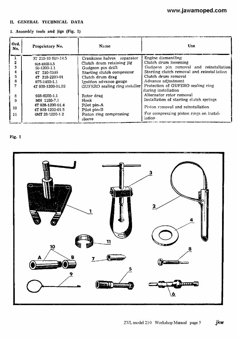
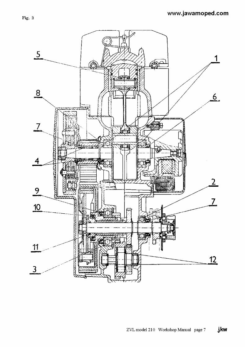
1. Assembly tools and jigs2. Moped lubrication — Lubrication Chart3. List of bearings, sealing rings and bushes4. Engine torque transmission — diagramand description
III. Engine
1. Removing engine from frame2. Removing cylinder head, cylinder and piston3. Grading of cylinders and pistons4. Clutch dismantling5. Carburettor6. Crankshaft
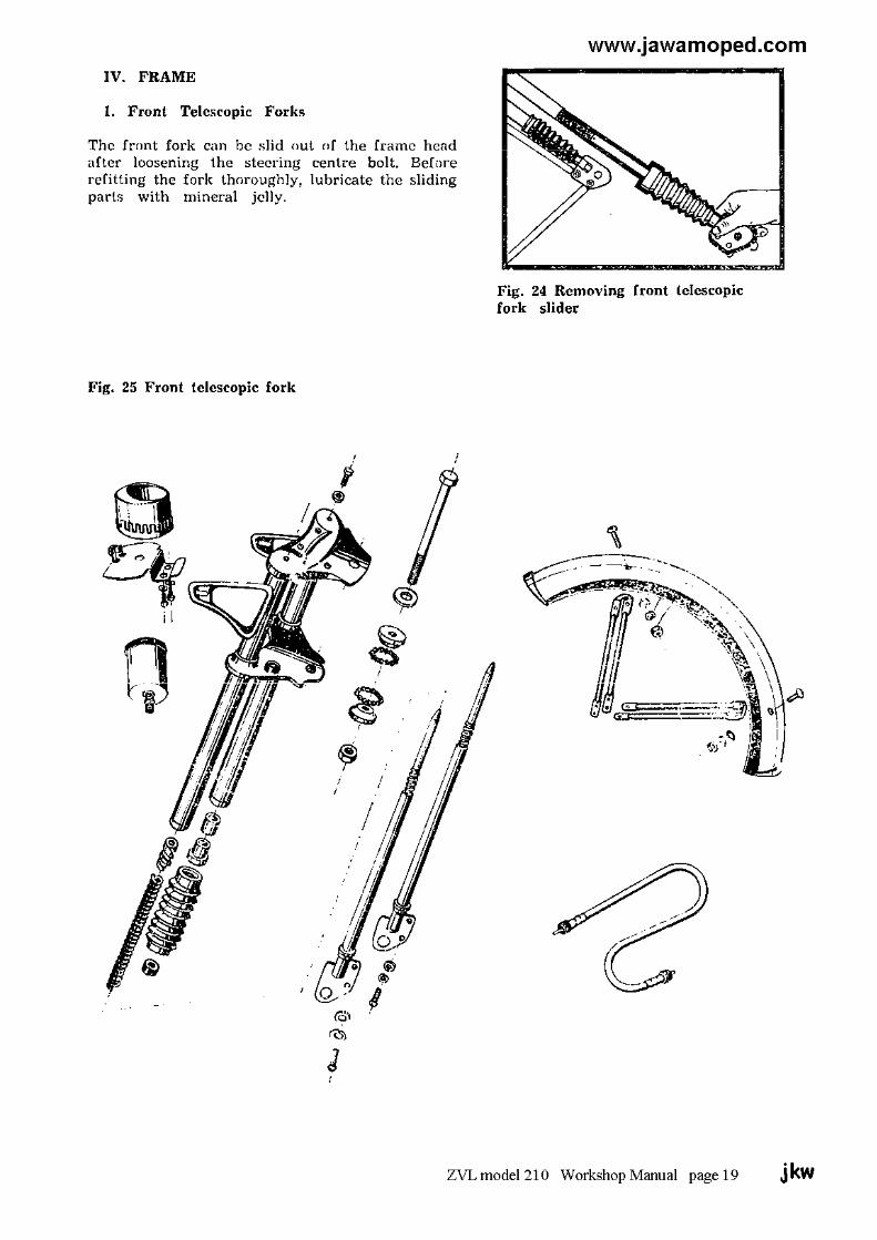
IV. Frame
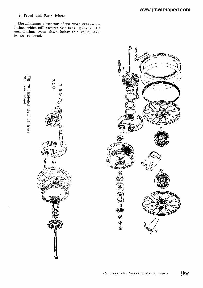
1. Front, telescopic fork2. Front, and rear wheel3. Rear wheel telescopic suspension
V. Electrical equipment
1. Alternator2. Ignition system3. Wiring diagram4. Diagnosing electronic ignition defects
VI. Causes of defects and their removal
I. MOPED SPECIFICATIONS
Engine type air cooled, two-stroke single-cylinder unitSwept volume 49 ccCylinder bore x piston stroke 39 x 41 mmEngine power output 1.75 kW at 5,000 rpm ± 8 %Clutches automatic, dry, centrifugalGearbox two-speed unitEngine to rear wheel 1st. speed overall ratio --- 1 : 24.4231 transmission ratio 2nd. speed overall ratio --- 1 : 13.7305Primary transmission indented beltSecondary transmission link chainPedal drive transmission ratio1 : 0.692Pedal-actuated starting gear overall ratio 1 : 0.0504Front suspension telescopic fork without shock absorbers
60 mm strokeRear suspension telescopic suspension units without shock
Absorber -- 60 mm strokeBrakes internal expanding shoe -- brakes controlled
by levers on handlebarsBrake dimensions 85 x 20 mmTyres 2¼ x 16"Wheels 1.60” (WH1) x 16”Inflation pressures - front tyre 196 kPa (2 atm) [ 28 psi ]
- rear tyre 245 kPa (2.5 atm.) [ 36 psi ]Moped dry weight 51 kgMoped running weight 54 kgRoad speed - sustained 35 km/hr.
- maximum 40 km/hr ± 5 %Fuel tank filling capacity 4 litresFuel reserve 0,7 litresMaximum climbable gradientwith rider weighing 75 kg 25 %Noise 70 decibelsIgnition system 6 volt, contactless with semiconductor
elementsSpark plug PAL N 7 R [ Champion L89CM L85 L86 ]
[ NGK B6HS Bosh W7AC ]Headlamp 6 v 21 wTail lamp 6 v 5 wSpeedometer lighting 6 v 2 wFuel consumption 1.8 litres/100 km at 27 km/hrLoad capacity, maximum 90 kg including 5 kg luggage on carrier
Note:When exceeding the load capacity, it is necessary to decrease themaximum speed proportionally
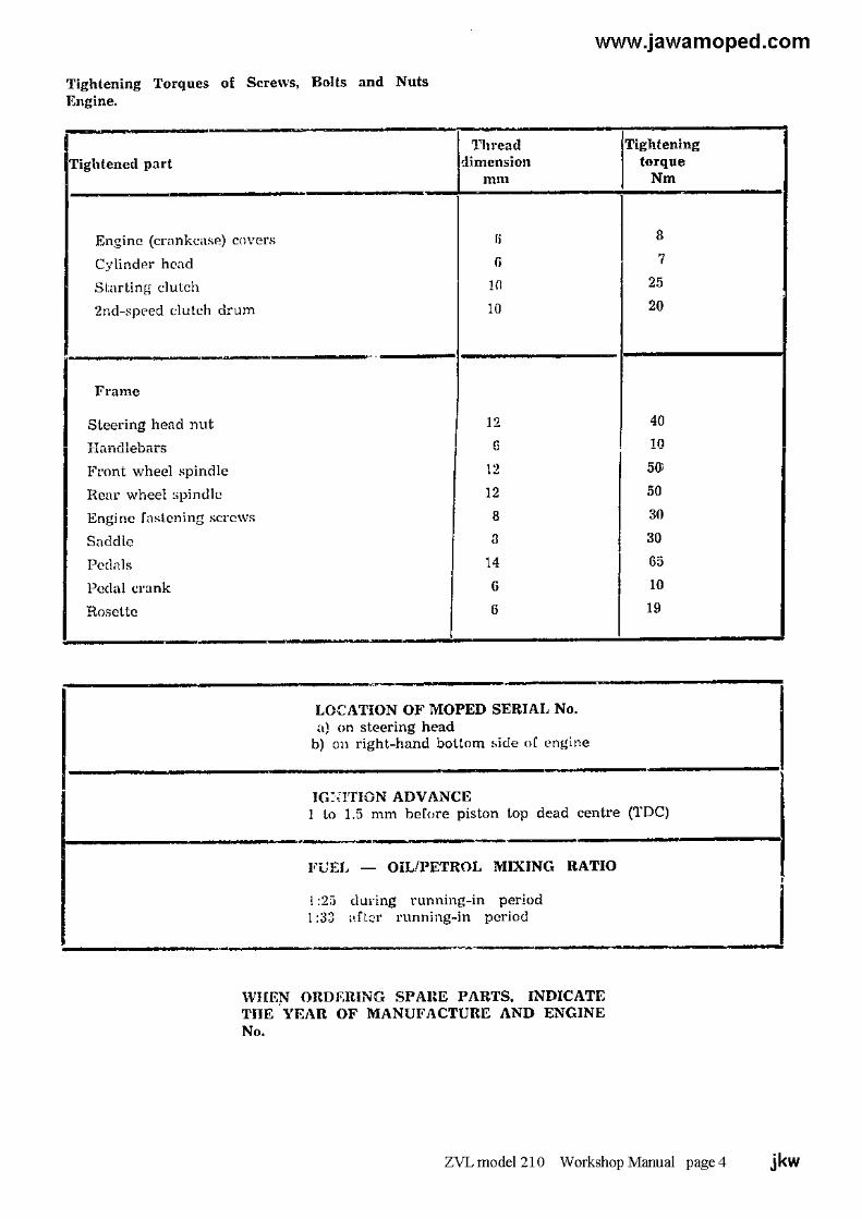
ZVL model 210 Workshop Manual Pages 1, 2 & 3 jkw

www.jawamoped.com
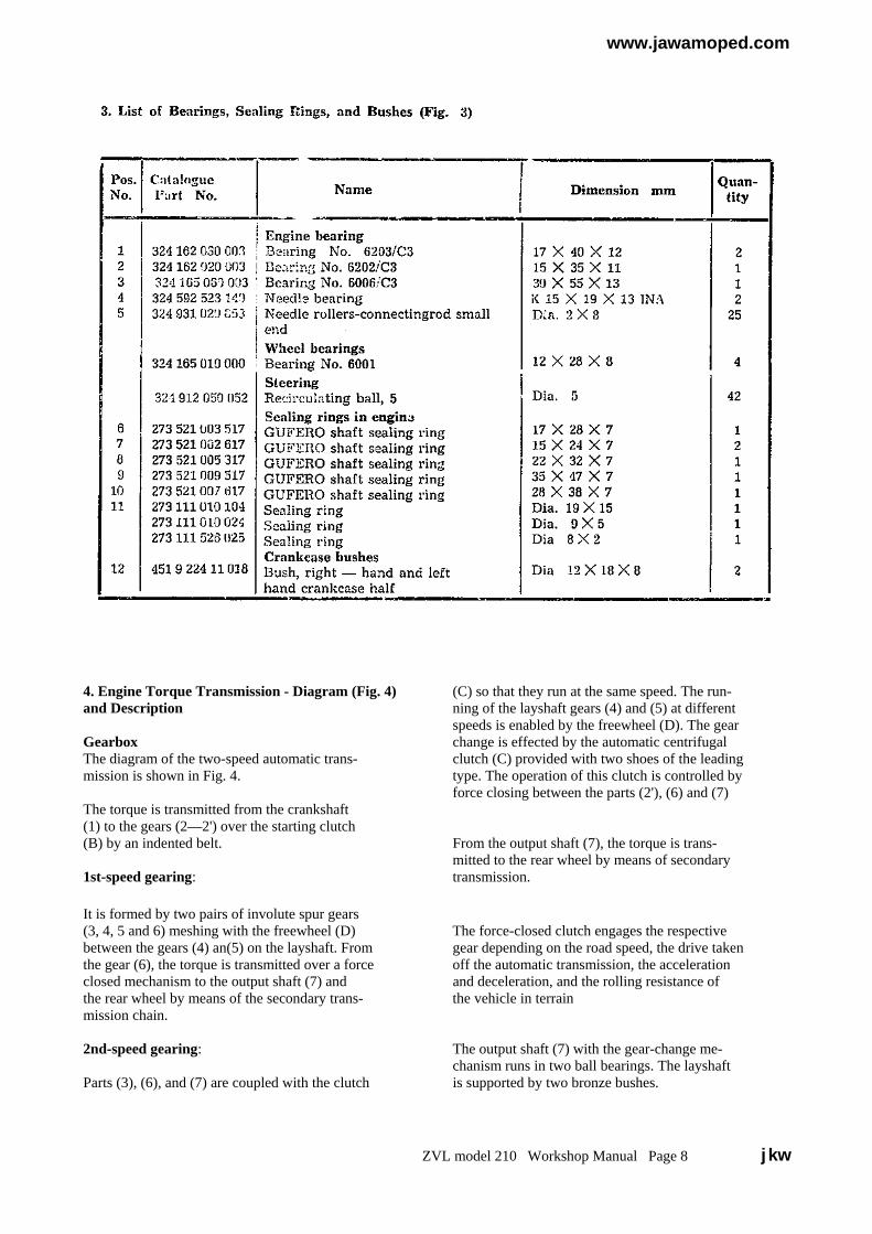
4. Engine Torque Transmission - Diagram (Fig. 4) (C) so that they run at the same speed. The run-and Description ning of the layshaft gears (4) and (5) at different
speeds is enabled by the freewheel (D). The gearGearbox change is effected by the automatic centrifugalThe diagram of the two-speed automatic trans- clutch (C) provided with two shoes of the leadingmission is shown in Fig. 4. type. The operation of this clutch is controlled by
force closing between the parts (2'), (6) and (7)The torque is transmitted from the crankshaft(1) to the gears (2—2') over the starting clutch(B) by an indented belt. From the output shaft (7), the torque is trans-
mitted to the rear wheel by means of secondary1st-speed gearing: transmission.
It is formed by two pairs of involute spur gears(3, 4, 5 and 6) meshing with the freewheel (D) The force-closed clutch engages the respectivebetween the gears (4) an(5) on the layshaft. From gear depending on the road speed, the drive takenthe gear (6), the torque is transmitted over a force off the automatic transmission, the accelerationclosed mechanism to the output shaft (7) and and deceleration, and the rolling resistance ofthe rear wheel by means of the secondary trans- the vehicle in terrainmission chain.
2nd-speed gearing: The output shaft (7) with the gear-change me-chanism runs in two ball bearings. The layshaft
Parts (3), (6), and (7) are coupled with the clutch is supported by two bronze bushes.
ZVL model 210 Workshop Manual Page 8 jkw
www.jawamoped.com
III ENGINE
1. Removing engine from framea) Remove the engine guards.b) Detach the spark plug cable, the fuel hose, and the
throttle cable.c) Disconnect the leads of the electrical equipment.d) Disconnect the chain of the secondary transmission.e) Disconnect the exhaust pipe from the engine.f) Remove screws fastening the engine to the frame,
and lift off the engine.
Clean well the surfaces of the engine, and drain the oilfrom the automatic transmission case. During enginedismantling, clean immediately all the removed partsand put them aside in the order of their removal, so thatthey can be reassembled correctly and in the shortestpossible time.
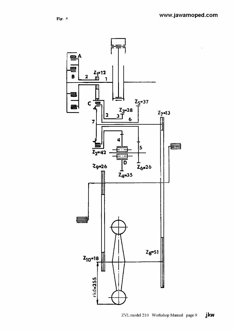
2. Removing cylinder head, cylinder and piston
a) Unscrew the four M6 nuts and lift them off togetherwith washers from the studs.
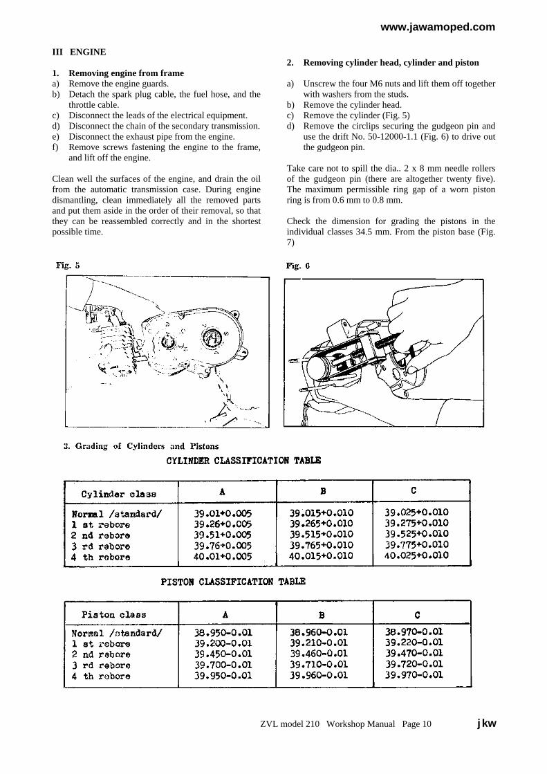
b) Remove the cylinder head.c) Remove the cylinder (Fig. 5)d) Remove the circlips securing the gudgeon pin and
use the drift No. 50-12000-1.1 (Fig. 6) to drive outthe gudgeon pin.
Take care not to spill the dia.. 2 x 8 mm needle rollersof the gudgeon pin (there are altogether twenty five).The maximum permissible ring gap of a worn pistonring is from 0.6 mm to 0.8 mm.
Check the dimension for grading the pistons in theindividual classes 34.5 mm. From the piston base (Fig.7)
ZVL model 210 Workshop Manual Page 10 jkw
www.jawamoped.com
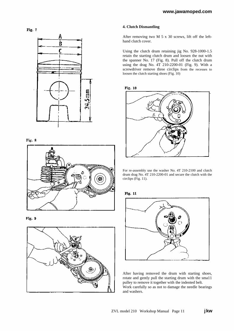
4. Clutch Dismantling
After removing two M 5 x 30 screws, lift off the left-hand clutch cover.
Using the clutch drum retaining jig No. 928-1000-1.5retain the starting clutch drum and loosen the nut withthe spanner No. 17 (Fig. 8). Pull off the clutch drumusing the drag No. 4T 210-2200-01 (Fig. 9). With ascrewdriver remove three circlips from the recesses toloosen the clutch starting shoes (Fig. 10)
For re-assembly use the washer No. 4T 210-2100 and clutchdrum drag No. 4T 210-2200-01 and secure the clutch with thecirclips (Fig. 11).
After having removed the drum with starting shoes,rotate and gently pull the starting drum with the sma11pulley to remove it together with the indented belt.Work carefully so as not to damage the needle bearingsand washers.
ZVL model 210 Workshop Manual Page 11 jkw
www.jawamoped.com
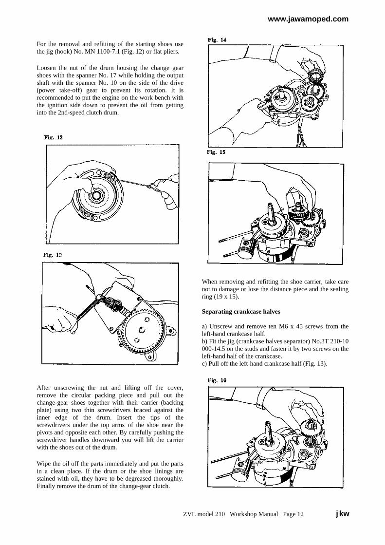
For the removal and refitting of the starting shoes usethe jig (hook) No. MN 1100-7.1 (Fig. 12) or flat pliers.
Loosen the nut of the drum housing the change gearshoes with the spanner No. 17 while holding the outputshaft with the spanner No. 10 on the side of the drive(power take-off) gear to prevent its rotation. It isrecommended to put the engine on the work bench withthe ignition side down to prevent the oil from gettinginto the 2nd-speed clutch drum.
After unscrewing the nut and lifting off the cover,remove the circular packing piece and pull out thechange-gear shoes together with their carrier (backingplate) using two thin screwdrivers braced against theinner edge of the drum. Insert the tips of thescrewdrivers under the top arms of the shoe near thepivots and opposite each other. By carefully pushing thescrewdriver handles downward you will lift the carrierwith the shoes out of the drum.
Wipe the oil off the parts immediately and put the partsin a clean place. If the drum or the shoe linings arestained with oil, they have to be degreased thoroughly.Finally remove the drum of the change-gear clutch.
When removing and refitting the shoe carrier, take carenot to damage or lose the distance piece and the sealingring (19 x 15).
Separating crankcase halves
a) Unscrew and remove ten M6 x 45 screws from theleft-hand crankcase half.b) Fit the jig (crankcase halves separator) No.3T 210-10000-14.5 on the studs and fasten it by two screws on theleft-hand half of the crankcase.c) Pull off the left-hand crankcase half (Fig. 13).
ZVL model 210 Workshop Manual Page 12 jkw
www.jawamoped.com
Removing gears
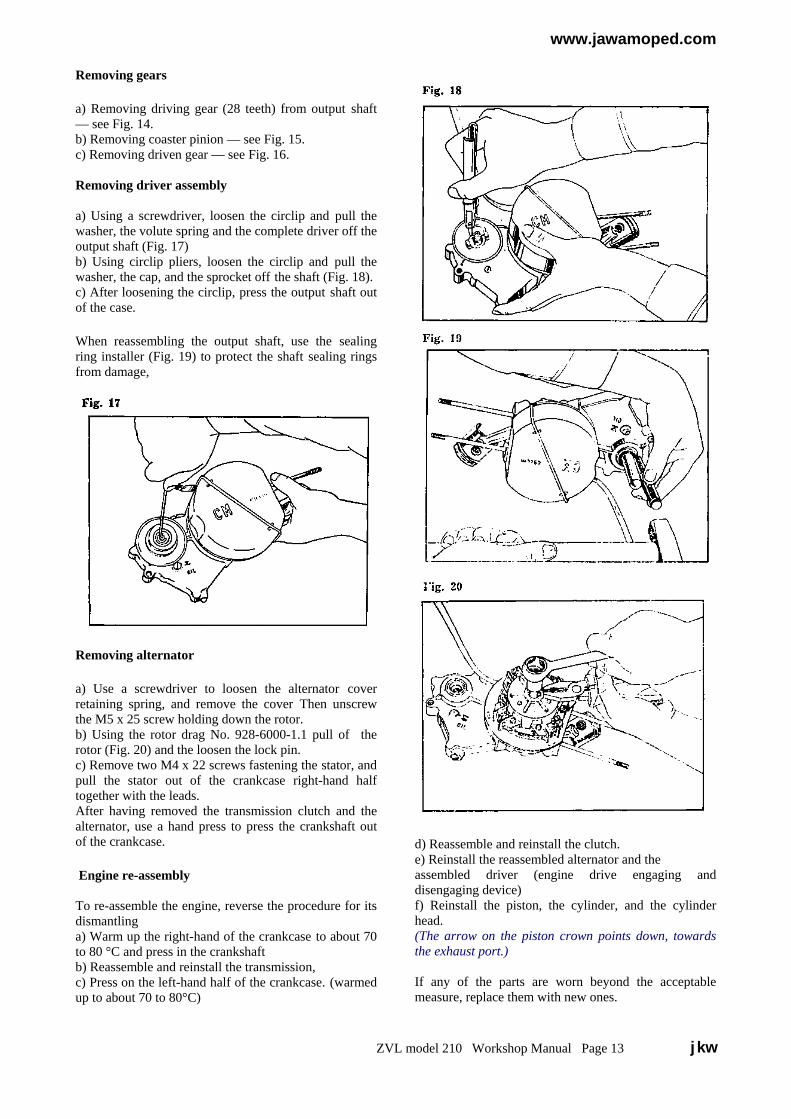
a) Removing driving gear (28 teeth) from output shaft— see Fig. 14.b) Removing coaster pinion — see Fig. 15.c) Removing driven gear — see Fig. 16.
Removing driver assembly
a) Using a screwdriver, loosen the circlip and pull thewasher, the volute spring and the complete driver off theoutput shaft (Fig. 17)b) Using circlip pliers, loosen the circlip and pull thewasher, the cap, and the sprocket off the shaft (Fig. 18).c) After loosening the circlip, press the output shaft outof the case.
When reassembling the output shaft, use the sealingring installer (Fig. 19) to protect the shaft sealing ringsfrom damage,
Removing alternator
a) Use a screwdriver to loosen the alternator coverretaining spring, and remove the cover Then unscrewthe M5 x 25 screw holding down the rotor.b) Using the rotor drag No. 928-6000-1.1 pull of therotor (Fig. 20) and the loosen the lock pin.c) Remove two M4 x 22 screws fastening the stator, andpull the stator out of the crankcase right-hand halftogether with the leads.After having removed the transmission clutch and thealternator, use a hand press to press the crankshaft outof the crankcase.
Engine re-assembly
To re-assemble the engine, reverse the procedure for itsdismantlinga) Warm up the right-hand of the crankcase to about 70to 80 °C and press in the crankshaftb) Reassemble and reinstall the transmission,c) Press on the left-hand half of the crankcase. (warmedup to about 70 to 80°C)
d) Reassemble and reinstall the clutch.e) Reinstall the reassembled alternator and theassembled driver (engine drive engaging anddisengaging device)f) Reinstall the piston, the cylinder, and the cylinderhead.(The arrow on the piston crown points down, towardsthe exhaust port.)
If any of the parts are worn beyond the acceptablemeasure, replace them with new ones.
ZVL model 210 Workshop Manual Page 13 jkw
www.jawamoped.com
Reassembling 2nd-speed clutchObserve utmost cleanliness during the clutch re-assembly. Degrease the drum (large pulley) with adegreasing agent (e.g. alcohol, acetone, clean petrol,etc) and wipe it dry with a clean cloth. The roughness ofthe drum working (friction) surface must be at least 0.8,i.e. the surface must be polished with fine emery paper.A rougher surface has an unfavourable effect on theservice life of the friction lining.Make sure that the GUFERO sealing ring (15 x 24 x 7)in the drum is not damaged. Put the shoe carrier (baseplate), with the two 2nd-speed shoes mounted inposition together with the regulating driver locatedbetween them into the drum. All parts must be dry,without any traces of oil.If oil has got between the joint faces during thedismantling, remove the 2nd-speed shoes and dip thecarrier in a solvent (degreasing agent). Then dry thecarrier thoroughly.The hard chrome-plated lands of the regulating driverwhich touch the brass friction layer on the shoes mustbe bright, clean and dry. Rotate the shoe carrier togetherwith the regulating driver anticlockwise and fit the partsin their position by a slight pressure of the hand.
Never touch the friction lining and the friction surfaceof the drum with greasy hands. Place the ,’O’ sealingring on the recess (clean and undamaged) of the carrierhub and locate the metal bush on the ,’O’ ring. Thenapply a tube of sufficient length and the same diameteras the bush on the bush, and by rotating and pressingdown the tube, press the bush through the ‘O’ ringinside the hub. Then install the inside driver whichensures that the regulating driver controls both shoes atthe same time. For this reason, the holes must beperfectly clean and the parts must have a certainclearance along the circumference with the exception ofthe contact areas.
Locate the circular sheet-metal washer and the clutchcover, and then screw down and tighten well the M10 x1.25 nut
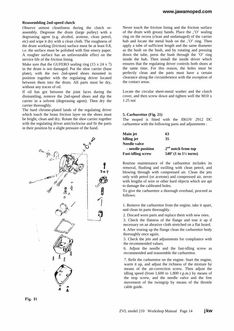
5. Carburettor (Fig. 21)The moped is fitted with the JIKOV 2912 DCcarburettor with the following parts and adjustments :
Main jet 63Idling jet 35Needle valve - needle position 2nd notch from topFast-idling screw 540º (1 to 1½ turns)
Routine maintenance of the carburettor includes itsremoval, flushing and swilling with clean petrol, andblowing through with compressed air. Clean the jetsonly with petrol (or acetone) and compressed air, neverwith lengths of wire or other hard objects which are aptto damage the calibrated holes.To give the carburettor a thorough overhaul, proceed asfollows:
1. Remove the carburettor from the engine, take it apart,and clean its parts thoroughly.2. Discard worn parts and replace them with new ones.3. Check the flatness of the flange and true it up ifnecessary on an abrasive cloth stretched on a flat board.4. After trueing up the flange clean the carburettor bodythoroughly once again.5. Check the jets and adjustments for compliance withthe recommended values.6. Adjust the needle and the fast-idling screw asrecommended and reassemble the carburettor.
7. Refit the carburettor on the engine. Start the engine,warm it up, and adjust the richness of the mixture bymeans of the air-correction screw. Then adjust theidling speed (from 1,600 to 1,800 r.p.m.) by means ofthe stop screw, and the needle valve and the freemovement of the twistgrip by means of the throttlecable guide.
ZVL model 210 Workshop Manual Page 14 jkw
www.jawamoped.com
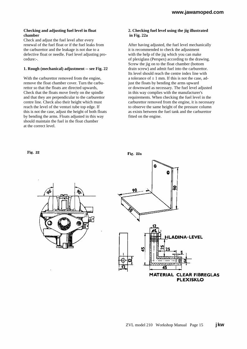
Checking and adjusting fuel level in float 2. Checking fuel level using the jig illustratedchamber in Fig. 22aCheck and adjust the fuel level after everyrenewal of the fuel float or if the fuel leaks from After having adjusted, the fuel level mechanicallythe carburettor and the leakage is not due to a it is recommended to check the adjustmentdefective float or needle. Fuel level adjusting pro- with the help of the jig which you can makecedure:-. of plexiglass (Perspex) according to the drawing.
Screw the jig on to the float chamber (bottom1. Rough (mechanical) adjustment -- see Fig. 22 drain screw) and admit fuel into the carburettor.
Its level should reach the centre index line withWith the carburettor removed from the engine, a tolerance of ± 1 mm. If this is not the case, ad-remove the float chamber cover. Turn the carbu- just the floats by bending the arms upwardrettor so that the floats are directed upwards, or downward as necessary. The fuel level adjustedCheck that the floats move freely on the spindle in this way complies with the manufacturer'sand that they are perpendicular to the carburettor requirements. When checking the fuel level in thecentre line. Check also their height which must carburettor removed from the engine, it is necessaryreach the level of the venturi tube top edge. If to observe the same height of the pressure columnthis is not the case, adjust the height of both floats as exists between the fuel tank and the carburettorby bending the arms. Floats adjusted in this way fitted on the engine.should maintain the fuel in the float chamberat the correct level.
ZVL model 210 Workshop Manual Page 15 jkw
www.jawamoped.com6. Crankshaft Removal and reinstallation
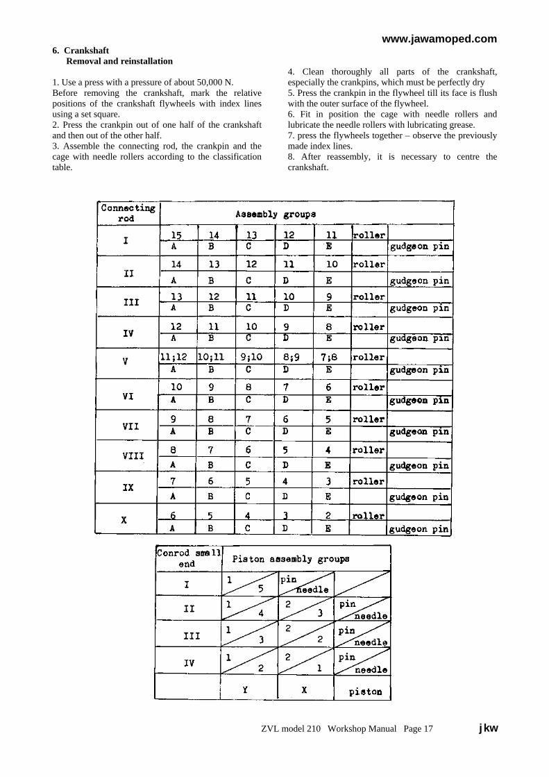
1. Use a press with a pressure of about 50,000 N.Before removing the crankshaft, mark the relativepositions of the crankshaft flywheels with index linesusing a set square.2. Press the crankpin out of one half of the crankshaftand then out of the other half.3. Assemble the connecting rod, the crankpin and thecage with needle rollers according to the classificationtable.
4. Clean thoroughly all parts of the crankshaft,especially the crankpins, which must be perfectly dry5. Press the crankpin in the flywheel till its face is flushwith the outer surface of the flywheel.6. Fit in position the cage with needle rollers andlubricate the needle rollers with lubricating grease.7. press the flywheels together – observe the previouslymade index lines.8. After reassembly, it is necessary to centre thecrankshaft.
ZVL model 210 Workshop Manual Page 17 jkw
www.jawamoped.com
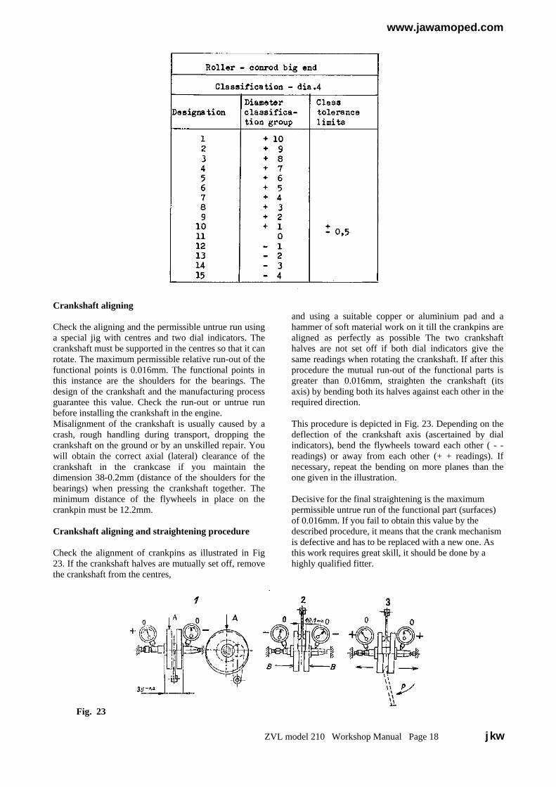
Crankshaft aligning
Check the aligning and the permissible untrue run usinga special jig with centres and two dial indicators. Thecrankshaft must be supported in the centres so that it canrotate. The maximum permissible relative run-out of thefunctional points is 0.016mm. The functional points inthis instance are the shoulders for the bearings. Thedesign of the crankshaft and the manufacturing processguarantee this value. Check the run-out or untrue runbefore installing the crankshaft in the engine.Misalignment of the crankshaft is usually caused by acrash, rough handling during transport, dropping thecrankshaft on the ground or by an unskilled repair. Youwill obtain the correct axial (lateral) clearance of thecrankshaft in the crankcase if you maintain thedimension 38-0.2mm (distance of the shoulders for thebearings) when pressing the crankshaft together. Theminimum distance of the flywheels in place on thecrankpin must be 12.2mm.
Crankshaft aligning and straightening procedure
Check the alignment of crankpins as illustrated in Fig23. If the crankshaft halves are mutually set off, removethe crankshaft from the centres,
and using a suitable copper or aluminium pad and ahammer of soft material work on it till the crankpins arealigned as perfectly as possible The two crankshafthalves are not set off if both dial indicators give thesame readings when rotating the crankshaft. If after thisprocedure the mutual run-out of the functional parts isgreater than 0.016mm, straighten the crankshaft (itsaxis) by bending both its halves against each other in therequired direction.
This procedure is depicted in Fig. 23. Depending on thedeflection of the crankshaft axis (ascertained by dialindicators), bend the flywheels toward each other ( - -readings) or away from each other (+ + readings). Ifnecessary, repeat the bending on more planes than theone given in the illustration.
Decisive for the final straightening is the maximumpermissible untrue run of the functional part (surfaces)of 0.016mm. If you fail to obtain this value by thedescribed procedure, it means that the crank mechanismis defective and has to be replaced with a new one. Asthis work requires great skill, it should be done by ahighly qualified fitter.
Fig. 23
ZVL model 210 Workshop Manual Page 18 jkw

www.jawamoped.com
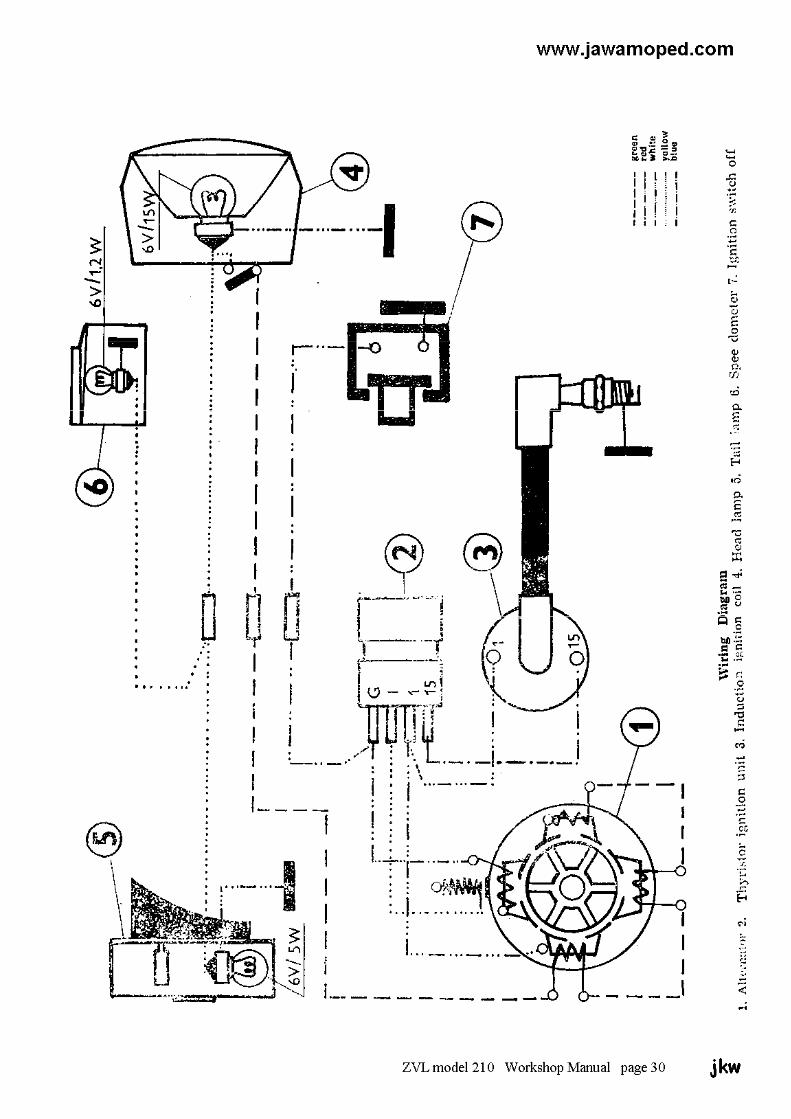
V. ELECTRICAL EQUIPMENT connected in series with an output of 20 W at avoltage of 6 V.
1. AlternatorElectric current is supplied by the alternator Another stator coil supplies current to the ignitionfitted with a rotor with permanent magnets. The coil and the thyristor block controlled by thelamps are fed with current from three stator coils pulse-forming stator coil.
Lamps:
Headlight 6 V / 21 W bulbTail light 6 V / 5 W bulbSpeedometer lighting 6 V / 2 W bulb(outside bulb fastening)Speedometer lighting 6 V / 1.2 W bulb(inside bulb fastening)
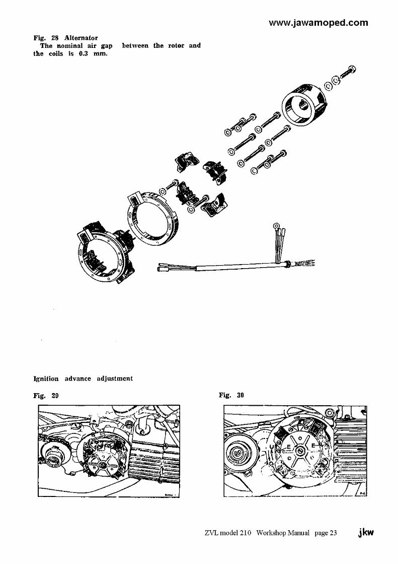
2. IgnitionTo adjust the ignition advance, turn the rotor
Contactless, thyristorized system with plastic in the direction of the arrow ,,A" (Fig. 29) till theencapsulated semiconductor device. The ignition index lines (timing marks) ,,B" on the rotor andcoil is enclosed in a cylindrical aluminium case. stator coincide. Insert an indicator or a depth slide
gauge into the spark plug hole and measureFeeding — generator coil the depth to the retracted piston. Then continueStarting — pulse-forming coil rotating the rotor in the direction of the arrowSpark plug — PAL N 7R ,,A" till the piston reaches its top position (T.D.C.).Plug point gap — 0.5 mmIgnition advance — 1-1.5 mm before T.D. The distance read off the indicator or depth
gauge from the point of the coincidence of theThe described ignition system of the moped does timing marks to the piston T.D.C. should be 1not require any maintenance apart from occasional to 1.5 mm. If this distance is greater, loosen thecleaning of the spark plug. Any defect which might screws (E) — Fig. 30, and turn the stator in theoccur is usually the result of unskilled interference direction indicated by the arrow ,,C". If the dis-or rough handling on the part of the user. Adjust- tance is smaller, turn the stator in the directionment of the ignition advance is likewise not ne- of the arrow ,,D".cessary as there are no parts subject to wear. Theonly instances in which the advance has to be re- Repeat this procedure till obtaining the specifiedadjusted is the working loose of the stator screws advance of 1 to 1.5 mm. Then retighten theor the removal of the alternator. Therefore refrain screws ,,E" and recheck the advance.from interfering with the ignition system in anyway. In the case of a defect, have the repair doneby a skilled electrician.
3. Moped Wiring Diagram(is placed on page 30)
ZVL model 210 Workshop Manual Page 22 jkw
www.jawamoped.com
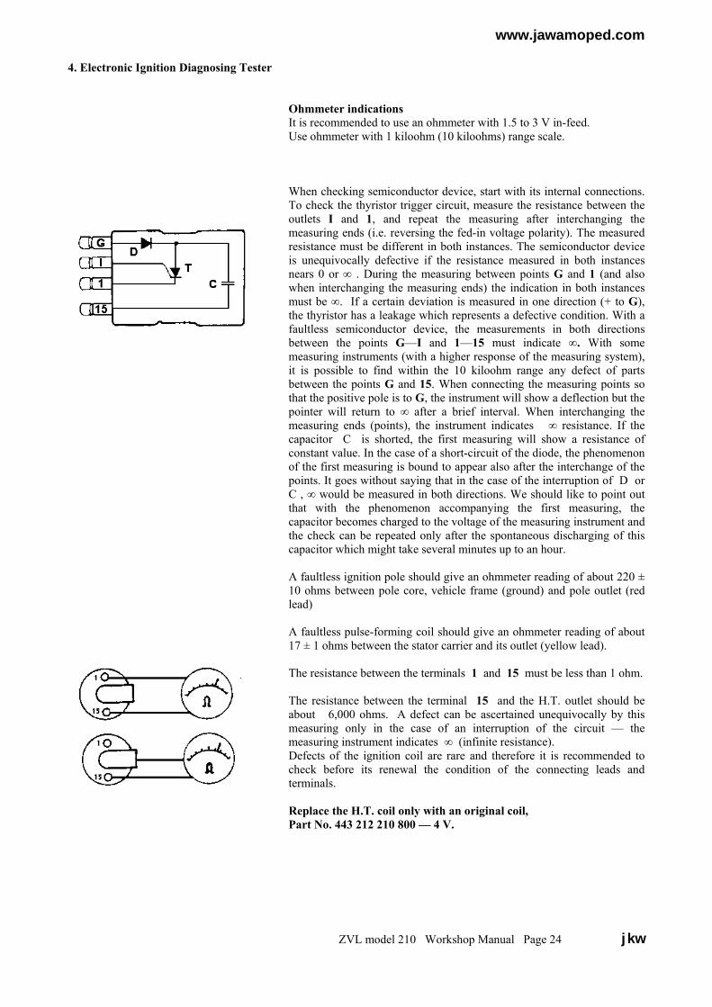
4. Electronic Ignition Diagnosing Tester
Ohmmeter indicationsIt is recommended to use an ohmmeter with 1.5 to 3 V in-feed.Use ohmmeter with 1 kiloohm (10 kiloohms) range scale.
When checking semiconductor device, start with its internal connections.To check the thyristor trigger circuit, measure the resistance between theoutlets I and 1, and repeat the measuring after interchanging themeasuring ends (i.e. reversing the fed-in voltage polarity). The measuredresistance must be different in both instances. The semiconductor deviceis unequivocally defective if the resistance measured in both instancesnears 0 or ∞ . During the measuring between points G and 1 (and alsowhen interchanging the measuring ends) the indication in both instancesmust be ∞. If a certain deviation is measured in one direction (+ to G),the thyristor has a leakage which represents a defective condition. With afaultless semiconductor device, the measurements in both directionsbetween the points G—I and 1—15 must indicate ∞. With somemeasuring instruments (with a higher response of the measuring system),it is possible to find within the 10 kiloohm range any defect of partsbetween the points G and 15. When connecting the measuring points sothat the positive pole is to G, the instrument will show a deflection but thepointer will return to ∞ after a brief interval. When interchanging themeasuring ends (points), the instrument indicates ∞ resistance. If thecapacitor C is shorted, the first measuring will show a resistance ofconstant value. In the case of a short-circuit of the diode, the phenomenonof the first measuring is bound to appear also after the interchange of thepoints. It goes without saying that in the case of the interruption of D orC , ∞ would be measured in both directions. We should like to point outthat with the phenomenon accompanying the first measuring, thecapacitor becomes charged to the voltage of the measuring instrument andthe check can be repeated only after the spontaneous discharging of thiscapacitor which might take several minutes up to an hour.
A faultless ignition pole should give an ohmmeter reading of about 220 ±10 ohms between pole core, vehicle frame (ground) and pole outlet (redlead)
A faultless pulse-forming coil should give an ohmmeter reading of about17 ± 1 ohms between the stator carrier and its outlet (yellow lead).
The resistance between the terminals 1 and 15 must be less than 1 ohm.
The resistance between the terminal 15 and the H.T. outlet should beabout 6,000 ohms. A defect can be ascertained unequivocally by thismeasuring only in the case of an interruption of the circuit — themeasuring instrument indicates ∞ (infinite resistance).Defects of the ignition coil are rare and therefore it is recommended tocheck before its renewal the condition of the connecting leads andterminals.
Replace the H.T. coil only with an original coil,Part No. 443 212 210 800 — 4 V.
ZVL model 210 Workshop Manual Page 24 jkw
www.jawamoped.com
VI. CAUSES OF DEFECTS AND THEIR REMOVAL
A. ENGINE Loss of power1. Clogged air cleaner.
Engine will not start 2. Clogged exhaust silencer.1. Shut fuel cock. 3. Damaged crankcase sealing ring.2. Empty fuel tank. 4. Damaged piston, cylinder or piston rings.3. Choked fuel hose, strainer or fuel jet. Water 5. Leaky cylinder head. in float chamber. 6. Maladjusted ignition advance.4. Faulty ignition -- carbon deposits on spark plug electrodes, defective spark plug insulator, Engine power is satisfactory, but acceleration is excessive plug point gap, defective thyristor device poor or peak speed cannot be attained. defective ignition coil or stator carrier.5. Over flooded engine. 1. Brake shoes are fouling the drums. Remedy: Shut off the fuel cock and work the 2. Under inflated tyres.pedals with the machine on its stand or pedal along 3. Slipping starting clutch or 2nd-speed clutchtill the engine fires. Use the decompressor if themoped is fitted with it. Then open the fuel cock.It may also be necessary to unscrew the spark B. TRANSMISSIONplug and clean it and to turn the engine severaltimes to expel excessive fuel through the sparkplug hole. Reinstall the spark plug and repeat the This chapter deals with the less frequent defectsstarting procedure. which can occur in operation.6. Slipping or defective starting clutch. This youcan ascertain by removing the crankcase cover on As regards identification of causes of incorrectthe ignition side when you will be able to see function of 2nd-speed engaging mechanisms,whether the crankshaft with the rotor is rotating. it is assumed that a rider of the specified weight
rides on the moped with correctly inflated tyres ona level road in calm weather and that the moped
Engine runs erratically has no contributory rolling resistance as, for in-stance, maladjusted brakes, and that the secondary
1. Overheated engine, transmission mechanisms have not been interfered2- Faulty spark plug, with, e.g. by exchanging the original sprocket for3. Partly obstructed fuel supply or choked main jet another one with a different number of teeth.4. Leaky crankcase.5. Faulty cable terminal.6. Faulty ignition.7. Imperfectly vented fuel tank.
ZVL model 210 Workshop Manual Page 25 jkw

www.jawamoped.com
Defect Cause RemovalSlipping 2nd speed clutch1. Oil on drum friction surface.2. Water on drum friction surface.3. Regulating driver (driving dog)
clamped between parts does not moveand does not expand 2nd Speed shoes.
4. Worn lining of second speed shoes.Regulating driver strikes against shoepivot during starting and does notforce shoes against drum innersurface.
1. Degrease drum surface and lining.2. Wipe dry drum surface and lining.3. Work free or renew driver. Possible
defect of M10 x 1.25 nut, eg.Obliquely cut thread.
4. Renew 2nd speed shoes
Engine will not startFaultless freewheel in rear wheel
2nd speed clutch faultless, indented beltrotates, starting clutch slips.1. Oil or water on lining.2. Worn or torn off lining, broken shoe.
1. Degrease or wipe dry.2. Renew starting shoe.
Engine starts but starting is difficult Resistance in pedal system (centralassembly)
Lubricate pedal cranks and shaft, & adjustcorrect tension of chain if it is too taut.
Engine starts only when pushingdown the pedal energetically
1. Excessive preload of starting shoesprings.
2. Starting shoes move with difficulty.3. 2nd speed clutch shoes foul the shoe
driver.
1. Renew or expand springs.
2. Work them free.3. Work free 2nd speed shoes.
Rear wheel rotates at idling speedwith moped propped on stand
1. Too high idling speed.2. GUFERO sealing ring not fully
pressed home in small pulley.3. Starting shoes do not retract fully.4. Starting shoes driven mostly when
starting clutch is warmed up. Probablyinterchanged shoes.
1. Decrease idling speed.2. Press sealing ring home ( flush with
pulley.3. Check chamfering of leaf spring edges4. Install shoes in their correct place.
Slipping starting clutch Worn friction lining. Renew shoes.Engine starts and runs, starting clutchin good working condition butmoped does not start moving in firstgear or moves for only a brief periodand then force closing is interrupted.Sometimes force closing is restoredwhen decreasing engine speed.
1. Freewheel in engine does not engagefirmly.
2. Damaged – worn face for freewheelrollers.
1. Change oil in transmission. Use oil oflower viscosity in frosty weather.
2. Renew freewheel gear.
When starting off at full throttle onlevel road, engine overspeeds in firstgear. This may not necessarily beconsidered a defect.
1. 2nd speed shoes move sluggishly.2. Increased frictional resistance between
regulating driver and shoe brass layer.
3. Engine has an output surpassing therecommended output or a differenttorque characteristic.
1. Work them free.2. Burnish hard chrome plated lands on
regulating driver, or renew the driver.Never lubricate contact areas asfriction damps vibration of 2nd speedshoes in final gear change state.
3. Not considered as defect as long asmoped peak speed is observed.
Accelerate with only partly open throttle.When starting off at full throttle onlevel road, the engine fails to attainthe required speed in first gear andsoon changes to the 2nd gear.This is normal when riding downhillbecause of decreased rollingresistance.
1. Insufficient engine power, mopedoften cannot attain its specified peakspeed.
1. Proceed as per section “Loss ofpower”
Changing from 1st to 2nd gear takeslonger than normal.
1. First to forth gear changes takeslonger because of cold clutch whichhas not yet attained its normal servicetemperature.
2. Oil or grease on regulating driver andshoe contact areas. Light vibrationmight occur in final stages of 2nd gearengagement.
1. Not regarded as defect.
2. Degrease
ZVL model 210 Workshop Manual Page 26 & 27 jkw

www.jawamoped.com
Defect Cause RemovalChanging from 1st to 2nd gear takesvery long or it does not take place atall.When the 2nd speed clutch is slidingit is not allowed to drive more than1km. High temperature can reducethe lifetime of driving belt.
Slipping 2nd speed clutch.1. Dirt or oil on friction areas.
2. Water on friction areas.
3. Interchanged 2nd speed shoes. It is alsopossible that the lining touches thedrum on the less effective trailingside.
1. Remove dirt, degrease drum andlinings with suitable degreasing agent.Then run in the clutch (formation offinal friction layer). Find cause ofcontamination (defective GUFEROsealing ring, O ring, burrs).
2. Without dismantling dry the clutch byletting it slip.
3. Replace shoes correctly or wait tilllining settles down on the wholeworking surface. Gears have to bechanged about 20 to 25 times before anew lining, made so that it touches thedrum on the leading edge, has settleddown to enable the function of thewhole working surface.
Changing from 1st to 2nd gear takes ashorter time than normal or a veryshort time. Exceptionally, the mopedeven starts from rest in 2nd gear or achange from 2nd to 1st gear takesplace when riding uphill.
Imperfect control of retraction of 2nd
speed shoes by regulating driver.1. check moveability of inner driver
(regulating driver contact under load).Hard chrome plated lands on inner drivermust be bright & undamaged.
1. This defect can be identified and alsoremoved by replacing inner driverwith a new one.
Changed properties of this contact can also be brought to light by a comparrison test of1st to 2nd gear change under load (at full throttle):A) Moving along in 2nd gear, decelerate by applying the brakes to change down from
the 2nd to the 1st gear. After releasing the brakes, the transmission will changesmoothly from the 1st to the 2nd speed.
B) Then decelerate by throttling down. This will release the regulating driver whichwill turn to the opposite side. On acceleration, the changing up from the 1st to the 2nd
gear is different – more sudden than in point A). This indicates that the regulatingdriver does not set readily on the inner driverand that the contact areas (lands) arenot in satisfactory condition.
2. The inner driver must turn and bearagainst the working surfaces with acertain peripheral clearance.
3. Defective chromium layer betweenregulating driver and brass layer onclutch shoe and /or destroyed brasslayer. Oxides formed there bypressure increase friction between theparts.
Other harmful factors:-4. Increased humidity of air in the space
of clutches.5. High working temperature of 2nd
speed clutch built up by changinggears in rapid succession (fifteen andmore times).
6. Thick layer of particles of abradedfriction material in the form of scalescovering the working surface.
2. Renew the parts. It is notrecommended to thin down faces ofthe parts by grinding.
3. Renew regulating driver, renew shoes.
4. Heat the space of clutches by a shortride without changing gears.
After every washing of the moped, startthe engine and let it warm up.5. A 10 to 15 second ride will suffice to
restore the original properties of theclutch. This is actually no defect but anormal property of friction linings.
6. Find and remove the cause of liningabrasion. Remove the layermechanically, for instance with fineabrasive (emery) paper, taking carenot to change the shape of the settleddown (bedded) lining.
Optimum gear change in model 210 moped, 2nd gear – 40 km/hr. at full throttle acceleration.(2nd speed clutch warmed up to service temperature).After starting from rest, the 2nd gear is engaged within a distance of 26 metres.Permissable gear-change tolerance limits: +30 m, -5 m.Engagement of 2nd gear begins at a distance of 18 meters and is complete in about 1.5 to 2 seconds.A cold 2nd speed clutch prolongs the distance by 9 meters (first to forth gear change).An overheated 2nd speed clutch shortens the distance by 3 meters.According to speedometer readings, the moped should attain about 24 km/hr. in 1st gear at full throttle andthe change to the 2nd gear should be completed at a speed of about 28 km/hr.
ZVL model 210 Workshop Manual Page 28 & 29 jkw