workshop manual - bellamoto.rs power dt... · fuel tank capacity 6.5 litres ... with water and...
TRANSCRIPT

WORKSHOP MANUAL633257
NRG Power DT

WORKSHOPMANUAL
NRG Power DT
The descriptions and illustrations given in this publication are not binding. While the basic features asdescribed and illustrated in this manual remain unchanged, PIAGGIO - GILERA reserves the right, atany time and without being required to update this publication beforehand, to make any changes to
components, parts or accessory supplies, which it considers necessary to improve the product or whichare required for manufacturing or construction reasons.
Not all versions shown in this publication are available in all Countries. The availability of individualversions should be confirmed with the official Piaggio sales network.
"© Copyright 2007 - PIAGGIO & C. S.p.A. Pontedera. All rights reserved. Reproduction of this publicationin whole or in part is prohibited."
PIAGGIO & C. S.p.A. - After-SalesV.le Rinaldo Piaggio, 23 - 56025 PONTEDERA (Pi)

WORKSHOP MANUALNRG Power DT
This workshop manual has been drawn up by Piaggio & C. Spa to be used by the workshops of Piaggio-Gilera dealers. This manual is addressed to Piaggio service mechanics who are supposed to have abasic knowledge of mechanics principles and of vehicle fixing techniques and procedures. Any importantchanges made to the vehicles or to specific fixing operations will be promptly reported by updates to thismanual. Nevertheless, no fixing work can be satisfactory if the necessary equipment and tools areunavailable. It is therefore advisable to read the sections of this manual relating to specific tools, alongwith the specific tool catalogue.
N.B. Provides key information to make the procedure easier to understand and carry out.
CAUTION Refers to specific procedures to carry out for preventing damages to the vehicle.
WARNING Refers to specific procedures to carry out to prevent injuries to the repairer.
Personal safety Failure to completely observe these instructions will result in serious risk of personalinjury.
Safeguarding the environment Sections marked with this symbol indicate the correct use of the vehicleto prevent damaging the environment.
Vehicle intactness The incomplete or non-observance of these regulations leads to the risk of seriousdamage to the vehicle and sometimes even the invalidity of the guarantee.


INDEX OF TOPICS
CHARACTERISTICS CHAR
TOOLING TOOL
MAINTENANCE MAIN
TROUBLESHOOTING TROUBL
ELECTRICAL SYSTEM ELE SYS
ENGINE FROM VEHICLE ENG VE
ENGINE ENG
SUSPENSIONS SUSP
BRAKING SYSTEM BRAK SYS
CHASSIS CHAS
PRE-DELIVERY PRE DE
TIME TIME


INDEX OF TOPICS
CHARACTERISTICS CHAR

Rules
This section describes general safety rules for any maintenance operations performed on the vehicle.
Safety rules
- If work can only be done on the vehicle with the engine running, make sure that the premises are well-
ventilated, using special extractors if necessary; never let the engine run in an enclosed area. Exhaust
fumes are toxic.
- The battery electrolyte contains sulphuric acid. Protect your eyes, clothes and skin. Sulphuric acid is
highly corrosive; in the event of contact with your eyes or skin, rinse thoroughly with abundant water
and seek immediate medical attention.
- The battery produces hydrogen, a gas that can be highly explosive. Do not smoke and avoid sparks
or flames near the battery, especially when charging it.
- Fuel is highly flammable and it can be explosive given some conditions. Do not smoke in the working
area, and avoid open flames or sparks.
- Clean the brake pads in a well-ventilated area, directing the jet of compressed air in such a way that
you do not breathe in the dust produced by the wear of the friction material. Even though the latter
contains no asbestos, inhaling dust is harmful.
Maintenance rules
- Use original PIAGGIO spare parts and lubricants recommended by the Manufacturer. Non-original or
non-conforming spares may damage the vehicle.
- Use only the appropriate tools designed for this vehicle.
- Always use new gaskets, sealing rings and split pins upon refitting.
- After removal, clean the components using non-flammable or low flash-point solvent. Lubricate all the
work surfaces except the tapered couplings before refitting.
- After refitting, make sure that all the components have been installed correctly and work properly.
- For removal, overhaul and refit operations use only tools with metric measures. Metric bolts, nuts and
screws are not interchangeable with coupling members with English measurement. Using unsuitable
coupling members and tools may damage the scooter.
- When carrying out maintenance operations on the vehicle that involve the electrical system, make
sure the electric connections have been made properly, particularly the ground and battery connections.
Characteristics NRG Power DT
CHAR - 2

Vehicle identification
Frame prefix: ZAPC45300 ÷ 1001
Engine prefix: C453M
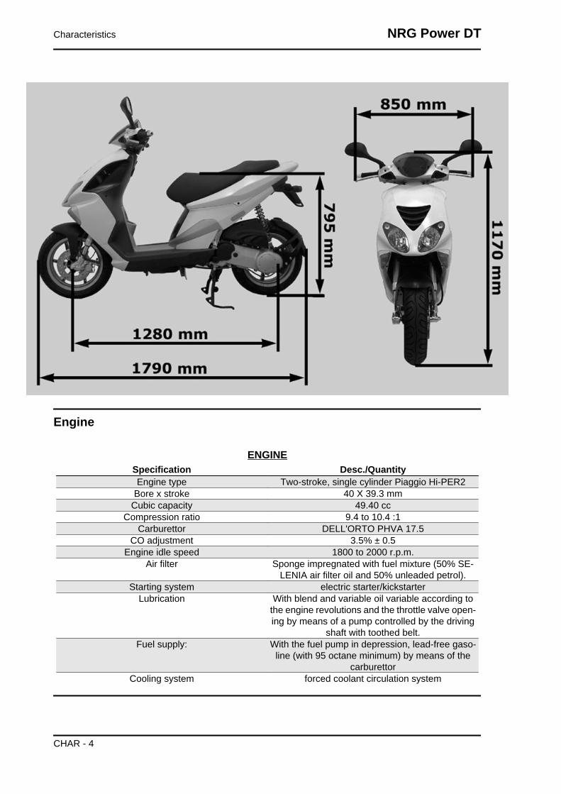
Dimensions and mass
DIMENSIONS AND MASSSpecification Desc./Quantity
Max length 1790 mm.Max width 850 mm.
Seat height 795 mm.Wheelbase 1280 mmDry weight 95 kg.
NRG Power DT Characteristics
CHAR - 3
Engine
ENGINESpecification Desc./QuantityEngine type Two-stroke, single cylinder Piaggio Hi-PER2
Bore x stroke 40 X 39.3 mmCubic capacity 49.40 cc
Compression ratio 9.4 to 10.4 :1Carburettor DELL'ORTO PHVA 17.5
CO adjustment 3.5% ± 0.5Engine idle speed 1800 to 2000 r.p.m.
Air filter Sponge impregnated with fuel mixture (50% SE-LENIA air filter oil and 50% unleaded petrol).
Starting system electric starter/kickstarterLubrication With blend and variable oil variable according to
the engine revolutions and the throttle valve open-ing by means of a pump controlled by the driving
shaft with toothed belt.Fuel supply: With the fuel pump in depression, lead-free gaso-
line (with 95 octane minimum) by means of thecarburettor
Cooling system forced coolant circulation system
Characteristics NRG Power DT
CHAR - 4

Transmission
TRANSMISSIONSpecification Desc./QuantityTransmission With automatic expandable pulley variator, torque
server, V belt, automatic clutch, gear reductionunit.
Capacities
CAPACITYSpecification Desc./QuantityRear hub oil Quantity : ~ 85 cc
Mixer oil 1.2 litresFuel tank capacity 6.5 litres (1.5 litres of reserve)
Electrical system
ELECTRICAL SYSTEMSpecification Desc./Quantity
Type of ignition Capacitive discharge type electronic ignition, withincorporated high voltage coil
Ignition advance (before TDC) Fixed 17° ± 1Recommended spark plug CHAMPION RN2C
Battery 12V-4AhMain fuse 7.5 AGenerator In alternate current with three output sections
Frame and suspensions
FRAME AND SUSPENSIONSSpecification Desc./QuantityChassis type Welded tubular steel chassis with stamped sheet
reinforcementsFront suspension upside-down hydraulic telescopic fork.
Front suspension travel 75 mmRear suspension With coaxial spring and hydraulic shock absorber.
Chassis to engine support with swinging arm.
Brakes
BRAKESSpecification Desc./QuantityFront brake Ø 220 mm disc brake with hydraulic linkage (r.h.
brake lever).
NRG Power DT Characteristics
CHAR - 5

Specification Desc./QuantityRear brake (Ø 110 mm) drum brake with expanding shoes,
mechanically controlled (lever on the handlebarleft hand end).
Wheels and tyres
WHEELS AND TYRESSpecification Desc./Quantity
Front tyre Tubeless 120/70-13"Rear tyre Tubeless 140/60 x 13''Wheels With circles of 3.50 x 13" in light alloy.
Secondary air
To clean the sponge filters of the secondary air
system, proceed as follows:
Unscrew the two studs ( 2) of the aluminium lid of
the secondary air box to access the polyurethane
sponge contained inside the box; after cleaning
with water and neutral soap, dry the sponge with
a clean cloth and reassemble the system, check-
ing that the steel blade is not warped and/or does
not guarantee the seal on its strike surface; re-
place if necessary.N.B.
UPON REFITTING, MAKE SURE TO CORRECT-LY FIT THE TAB IN ITS FITTING ON THE TWOPLASTIC AND ALUMINIUM COVERS.CAUTION
DURING THE OPERATION, CHECK THE IN-TEGRITY AND SEAL OF THE TWO SLEEVES(3) IN RUBBER LOCATED AT THE ENDS OFTHE SECONDARY AIR HOSE; IF NECESSARY,REPLACE THEM USING NEW CLAMPS TOFASTEN.
Carburettor
50cc Version
Characteristics NRG Power DT
CHAR - 6
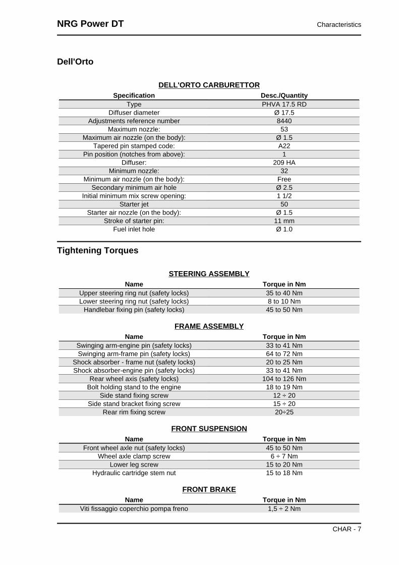
Dell'Orto
DELL'ORTO CARBURETTORSpecification Desc./Quantity
Type PHVA 17.5 RDDiffuser diameter Ø 17.5
Adjustments reference number 8440Maximum nozzle: 53
Maximum air nozzle (on the body): Ø 1.5Tapered pin stamped code: A22
Pin position (notches from above): 1Diffuser: 209 HA
Minimum nozzle: 32Minimum air nozzle (on the body): Free
Secondary minimum air hole Ø 2.5Initial minimum mix screw opening: 1 1/2
Starter jet 50Starter air nozzle (on the body): Ø 1.5
Stroke of starter pin: 11 mmFuel inlet hole Ø 1.0
Tightening Torques
STEERING ASSEMBLYName Torque in Nm
Upper steering ring nut (safety locks) 35 to 40 NmLower steering ring nut (safety locks) 8 to 10 Nm
Handlebar fixing pin (safety locks) 45 to 50 Nm
FRAME ASSEMBLYName Torque in Nm
Swinging arm-engine pin (safety locks) 33 to 41 NmSwinging arm-frame pin (safety locks) 64 to 72 Nm
Shock absorber - frame nut (safety locks) 20 to 25 NmShock absorber-engine pin (safety locks) 33 to 41 Nm
Rear wheel axis (safety locks) 104 to 126 NmBolt holding stand to the engine 18 to 19 Nm
Side stand fixing screw 12 ÷ 20Side stand bracket fixing screw 15 ÷ 20
Rear rim fixing screw 20÷25
FRONT SUSPENSIONName Torque in Nm
Front wheel axle nut (safety locks) 45 to 50 NmWheel axle clamp screw 6 ÷ 7 Nm
Lower leg screw 15 to 20 NmHydraulic cartridge stem nut 15 to 18 Nm
FRONT BRAKEName Torque in Nm
Viti fissaggio coperchio pompa freno 1,5 ÷ 2 Nm
NRG Power DT Characteristics
CHAR - 7

Name Torque in NmBrake pump support fixing screw 7 to 10 Nm
Brake fluid pump - hose fitting 13 to 18 NmBrake fluid tube - calliper fitting 20 to 25 Nm
Calliper tightening screw 20 to 25 NmDisc tightening screw (safety locks - lock with
LOCTITE THREADLOCK MEDIUM TYPE 243)6 ÷ 7 Nm
Oil bleed screw 7 to 10 NmCalliper coupling screw 20 to 25 Nm
ENGINE ASSEMBLYName Torque in Nm
Clutch bell nut 40 to 44 NmClutch lock ring nut 55 ÷ 60
nut locking driving pulley on the crankshaft 40 to 44 NmStart-up lever screw 12 ÷ 13
Flywheel nut 40 to 44 NmFlywheel fan screws 3 ÷ 4
Half-crank case joint bolts 12 ÷ 13Bolts holding exhaust pipe to the crankcase 22 ÷ 24
Screws holding the filter box to the crank case 4 ÷ 5Head nuts 10 ÷ 11
Starter screws 12 ÷ 13Ignition spark plug 25 ÷ 30
Hub oil drainage cap 3 ÷ 5Oil hub level dipstick ManualRear hub cap screws 12 ÷ 13
Transmission cover screws 12 ÷ 13Inlet manifold screws 8 ÷ 9
Flywheel hood fixing screws 1 ÷ 2Cylinder hood fixing screws 3.5 ÷ 5
Stator clamping screws 3 ÷ 4Pick-Up clamping screw 4 ÷ 5Mixer clamping screws 3 ÷ 4
Screw fixing brake lever to the journal on the en-gine
12 ÷ 13
Overhaul data
Assembly clearances
Cylinder - piston assy.
COUPLING BETWEEN PISTON AND CYLINDERName Initials Cylinder Piston Play on fitting
Standard coupling M 40.005 - 40.012 39.943 - 39.95 0.055 - 0.069Standard coupling N 40.012 - 40.019 39.95 - 39.957 0.055 - 0.069Standard coupling O 40.019 - 40.026 39.957 - 39.964 0.055 - 0.069Standard coupling P 40.026 - 40.033 39.964 - 39.971 0.055 - 0.069coupling 1st over-
sizeM1 40.205 - 40.212 40.143 - 40.15 0.055 - 0.069
Characteristics NRG Power DT
CHAR - 8
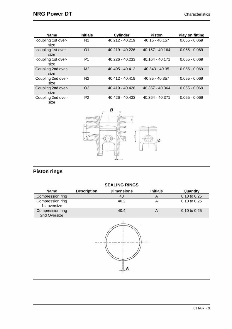
Name Initials Cylinder Piston Play on fittingcoupling 1st over-
sizeN1 40.212 - 40.219 40.15 - 40.157 0.055 - 0.069
coupling 1st over-size
O1 40.219 - 40.226 40.157 - 40.164 0.055 - 0.069
coupling 1st over-size
P1 40.226 - 40.233 40.164 - 40.171 0.055 - 0.069
Coupling 2nd over-size
M2 40.405 - 40.412 40.343 - 40.35 0.055 - 0.069
Coupling 2nd over-size
N2 40.412 - 40.419 40.35 - 40.357 0.055 - 0.069
Coupling 2nd over-size
O2 40.419 - 40.426 40.357 - 40.364 0.055 - 0.069
Coupling 2nd over-size
P2 40.426 - 40.433 40.364 - 40.371 0.055 - 0.069
Piston rings
SEALING RINGSName Description Dimensions Initials Quantity
Compression ring 40 A 0.10 to 0.25Compression ring
1st oversize40.2 A 0.10 to 0.25
Compression ring2nd Oversize
40.4 A 0.10 to 0.25
NRG Power DT Characteristics
CHAR - 9

Crankcase - crankshaft - connecting rod
AXIAL CLEARANCE BETWEEN CRANKCASE, CRANKSHAFT AND CONNECTING RODName Description Dimensions Initials Quantity
Connecting rod 11.750-0.05 A clearance E = 0.25to 0.50
shoulder washer 0.5 ± 0.03 G clearance E = 0.25to 0.50 - clearance
F = 0.20 to 0.75Half-shaft, trans-
mission side13.75+0.040 C clearance E = 0.25
to 0.50 - clearanceF = 0.20 to 0.75
Flywheel-side half-shaft
13.75+0.040 D clearance E = 0.25to 0.50 - clearance
F = 0.20 to 0.75Lining between the
shoulders40.64 H clearance E = 0.25
to 0.50 - clearanceF = 0.20 to 0.75
Cage 11.800-0.35 B clearance F = 0.20to 0.75
Slot packing system
- Fit the cylinder without installing the basic gasket.
- Apply a centimetre dial gauge on the special tool
and zero it on the ground plane
- Fit the tool to the top of the cylinder fixing it with
two nuts to the studbolts and take the piston to the
T.D.C.
- The thickness of the gasket to fit will change de-
pending on the value detected. For this purpose,
there are three with different thicknesses
Specific tooling020272Y Piston position check tool
Characteristics NRG Power DT
CHAR - 10

SHIMMING SYSTEM
Name Measure A ThicknessShimming 2.80 ÷ 3.04 0,4Shimming 3.04 ÷ 3.24 0,6Shimming 3.25 ÷ 3.48 0,8
Products
TABLE OF RECOMMENDED PRODUCTSProduct Description Specifications
AGIP ROTRA 80W-90 Rear hub oil SAE 80W/90 Oil that exceeds therequirements of API GL3 specifi-
cationsAGIP CITY HI TEC 4T Oil to lubricate flexible transmis-
sions (brake, throttle control andmixer, odometer)
Oil for 2-stroke engines: SAE5W-40, API SL, ACEA A3, JASO
MAAGIP FILTER OIL Oil for air filter sponge Mineral oil with specific additives
for increased adhesivenessAGIP CITY TEC 2T Mixer oil synthetic oil for 2-stroke engines:
JASO FC, ISO-L-EGDAGIP GP 330 Grease for brake levers, throttle White calcium complex soap-
based spray grease with NLGI 2;ISO-L-XBCIB2
AGIP GREASE SM 2 Grease for the tone wheel revolv-ing ring
Soap-based lithium grease con-taining NLGI 2 Molybdenum di-sulphide; ISO-L-XBCHB2, DIN
KF2K-20AGIP BRAKE 4 Brake fluid FMVSS DOT 4 Synthetic fluid
MONTBLANC MOLYBDENUMGREASE
Grease for driven pulley shaft ad-justing ring and movable driven
pulley housing
Grease with Molybdenum disul-phide
AGIP GREASE PV2 Grease for the steering bearings,pin seats and swinging arm
White anhydrous-calcium basedgrease to protect roller bearings;temperature range between -20C and +120 C; NLGI 2; ISO-L-
XBCIB2.
NRG Power DT Characteristics
CHAR - 11

Characteristics NRG Power DT
CHAR - 12

INDEX OF TOPICS
TOOLING TOOL

TOOLSStores code Description
001330Y Tool for fitting steering seats
001467Y006 Pliers to extract 20 mm bearings
001467Y007 Driver for OD 54 mm bearing
001467Y009 Driver for OD 42 mm bearings
001467Y013 Pliers to extract ø 15-mm bear-ings
001467Y014 Pliers to extract ø 15-mm bear-ings
Tooling NRG Power DT
TOOL - 2

Stores code Description001467Y017 Bell for bearings, outside Ø 39
mm
001467Y021 Extraction pliers for ø 11 mmbearings
002465Y Pliers for circlips
006029Y Punch for fitting fifth wheel seaton steering tube
020004Y Punch for removing fifth wheelsfrom headstock
020055Y Wrench for steering tube ring nut
020150Y Air heater support
NRG Power DT Tooling
TOOL - 3

Stores code Description020151Y Air heater
020162Y Flywheel extractor
020163Y Crankcase splitting plate
020164Y Driven pulley assembly sheath
020165Y Start-up crown lock
020166Y Pin lock fitting tool
Tooling NRG Power DT
TOOL - 4
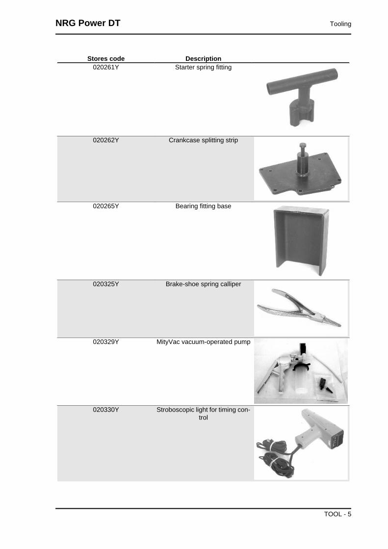
Stores code Description020261Y Starter spring fitting
020262Y Crankcase splitting strip
020265Y Bearing fitting base
020325Y Brake-shoe spring calliper
020329Y MityVac vacuum-operated pump
020330Y Stroboscopic light for timing con-trol
NRG Power DT Tooling
TOOL - 5
Stores code Description020331Y Digital multimeter
020332Y Digital rev counter
020334Y Multiple battery charger
020335Y Magnetic support for dial gauge
Tooling NRG Power DT
TOOL - 6
Stores code Description020350Y Electrical system check instru-
ment
020357Y 32 x 35 mm adaptor020359Y 42x47-mm adaptor
020376Y Adaptor handle
020412Y 15 mm guide
020456Y Ø 24 mm adaptor
NRG Power DT Tooling
TOOL - 7

Stores code Description020483Y 30 mm guide
020565Y Flywheel lock calliper spanner
020625Y Kit for sampling gas from the ex-haust manifold
494929Y Exhaust fumes analyser
Tooling NRG Power DT
TOOL - 8

INDEX OF TOPICS
MAINTENANCE MAIN

Maintenance chart
EVERY 2 YEARSAction
Brake fluid - change
AFTER 1000 KM50'
ActionHub oil - changeOil mixer/throttle linkage - adjustmentOdometer cable - greasingSteering - adjustmentBrake control levers - greasingBrake fluid level - checkSafety locks - checkElectrical system and battery - checkTyre pressure and wear - checkVehicle and brake test - road test
AFTER 5000 KM, 25000 KM, 35000 KM AND 55000 KM40'
ActionHub oil level - checkSpark plug/electrode gap - replacementAir filter - cleanOil mixer/throttle linkage - adjustmentBrake control levers - greasingBrake pads - check condition and wearBrake fluid level - checkElectrical system and battery - checkTyre pressure and wear - checkVehicle and brake test - road test
AFTER 10000 KM, 50000 KM95'
ActionHub oil - changeSpark plug/electrode gap - replacementAir filter - cleanIdling speed (*) - adjustmentOil mixer/throttle linkage - adjustmentVariable speed rollers - replacementOdometer cable - greasingDriving belt - checkSteering - adjustmentBrake control levers - greasingBrake pads - check condition and wearBrake fluid level - checkTransmission elements - lubricationSafety locks - check
Maintenance NRG Power DT
MAIN - 2

ActionSuspensions - checkElectrical system and battery - checkHeadlight - adjustmentTyre pressure and wear - checkVehicle and brake test - road test
(*) See regulations in the «Adjusting the idle speed» section
AFTER 15000 KM AND 45000 KM
65'Action
Hub oil level - checkSpark plug/electrode gap - replacementAir filter - cleanOil mixer/throttle linkage - adjustmentDriving belt - replacementBrake control levers - greasingBrake pads - check condition and wearBrake fluid level - checkElectrical system and battery - checkTyre pressure and wear - checkSAS box (sponge) (**) - cleaningVehicle and brake test - road test
(**) See regulations in the «Secondary air system» section
AFTER 20000 KM AND 40000 KM
110'Action
Hub oil - changeSpark plug/electrode gap - replacementAir filter - cleanIdling speed (*) - adjustmentCylinder cooling system - check/cleaningOil mixer/throttle linkage - adjustmentDriving belt - checkVariable speed rollers - replacementMixer belt - replacementOdometer cable - greasingSteering - adjustmentBrake control levers - greasingBrake pads - check condition and wearBrake fluid level - checkTransmission elements - lubricationSafety locks - checkSuspensions - checkElectrical system and battery - checkHeadlight - adjustmentTyre pressure and wear - checkVehicle and brake test - road test
(*) See section «Adjusting the idle speed»
AFTER 30000 KM
130'
NRG Power DT Maintenance
MAIN - 3

ActionHub oil - changeSpark plug/electrode gap - replacementAir filter - cleanIdling speed (*) - adjustmentOil mixer/throttle linkage - adjustmentDriving belt - replacementVariable speed rollers - replacementOdometer cable - greasingSteering - adjustmentBrake control levers - greasingBrake pads - check condition and wearFlexible brake tubes - replacementBrake fluid level - checkTransmission elements - lubricationSafety locks - checkSuspensions - checkElectrical system and battery - checkHeadlight - adjustmentTyre pressure and wear - checkSAS box (sponge) (**) - cleaningVehicle and brake test - road test
(*) See regulations in the «Adjusting the idle speed» section(**) See regulations in the «Secondary air system» section
AFTER 60000 KM
150'Action
Hub oil - changeSpark plug/electrode gap - replacementAir filter - cleanIdling speed (*) - adjustmentCylinder cooling system - check/cleaningOil mixer/throttle linkage - adjustmentDriving belt - replacementVariable speed rollers - replacementMixer belt - replacementOdometer cable - greasingSteering - adjustmentBrake control levers - greasingBrake pads - check condition and wearFlexible brake tubes - replacementBrake fluid level - checkTransmission elements - lubricationSafety locks - checkSuspensions - checkElectrical system and battery - checkHeadlight - adjustmentTyre pressure and wear - checkSAS box (sponge) (**) - cleaningVehicle and brake test - road test
(*) See regulations in the «Adjusting the idle speed» section(**) See regulations in the «Secondary air system» section
Maintenance NRG Power DT
MAIN - 4
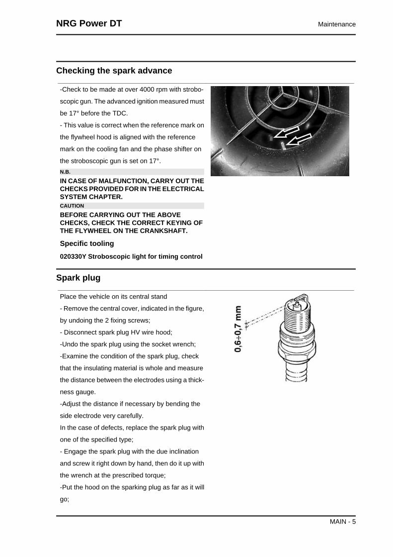
Checking the spark advance
-Check to be made at over 4000 rpm with strobo-
scopic gun. The advanced ignition measured must
be 17° before the TDC.
- This value is correct when the reference mark on
the flywheel hood is aligned with the reference
mark on the cooling fan and the phase shifter on
the stroboscopic gun is set on 17°.N.B.
IN CASE OF MALFUNCTION, CARRY OUT THECHECKS PROVIDED FOR IN THE ELECTRICALSYSTEM CHAPTER.CAUTION
BEFORE CARRYING OUT THE ABOVECHECKS, CHECK THE CORRECT KEYING OFTHE FLYWHEEL ON THE CRANKSHAFT.
Specific tooling020330Y Stroboscopic light for timing control
Spark plug
Place the vehicle on its central stand
- Remove the central cover, indicated in the figure,
by undoing the 2 fixing screws;
- Disconnect spark plug HV wire hood;
-Undo the spark plug using the socket wrench;
-Examine the condition of the spark plug, check
that the insulating material is whole and measure
the distance between the electrodes using a thick-
ness gauge.
-Adjust the distance if necessary by bending the
side electrode very carefully.
In the case of defects, replace the spark plug with
one of the specified type;
- Engage the spark plug with the due inclination
and screw it right down by hand, then do it up with
the wrench at the prescribed torque;
-Put the hood on the sparking plug as far as it will
go;
NRG Power DT Maintenance
MAIN - 5

- Refit the central flap.CAUTION
THE SPARK PLUG MUST BE REMOVED WHENTHE MOTOR IS COLD. THE SPARK PLUGMUST BE REPLACED EVERY 5000 KM. USEOF STARTERS NOT CONFORMING OR SPARKPLUGS NOT THOSE DESCRIBED CAN SERI-OUSLY DAMAGE THE ENGINE.
CharacteristicRecommended spark plug
CHAMPION RN2C
Electric characteristicElectrode gap
0.6 to 0.7 mm.
Locking torques (N*m)Spark plug 25 - 30 Nm
Hub oil
Check
Do the following to check the correct level:
1) Stand the vehicle on the centre-stand on flat
ground;
2) Remove the dipstick «A», and dry it with a clean
cloth. Reinsert it, screwing it in all the way;
3) Remove the stick and check that the oil level is
slightly over the second notch starting from the
lower end;
4) Screw the dipstick back in, checking that it is
locked in place.
Recommended productsAGIP ROTRA 80W-90 Rear hub oil
SAE 80W/90 Oil that exceeds the requirements of
API GL3 specifications
Maintenance NRG Power DT
MAIN - 6

Replacement
- Remove oil filler cap «A».
- Loosen oil draining cap «B» and allow for the
system to drain completely.
- Refit the draining cap and refill the hub with the
prescribed oil.
CharacteristicRear hub oil
~ 85 cc
Air filter
-Remove the cap of the purifier, unscrewing the six
clamping screws and removing the filter.
Cleaning:
-Wash with water and neutral soap.
- Dry with a clean cloth and short blasts of com-
pressed air.
-Saturate with a 50% mixture of gasoline and oil.
-Drip dry the filter and then squeeze it between the
hands without wringing.
-Let it dry and refit it again.CAUTION
NEVER RUN THE ENGINE WITHOUT THE AIRFILTER, THIS WOULD RESULT IN AN EXCES-SIVE WEAR OF THE PISTON AND CYLINDER.
Recommended productsAGIP FILTER OIL Oil for air filter sponge
Mineral oil with specific additives for increased ad-
hesiveness
NRG Power DT Maintenance
MAIN - 7
Checking the ignition timing
- Adjust the control cables:
Mix cable: see procedure indicated in "Mixer tim-
ing".
Throttle cable: adjust the set screw on the carbu-
rettor in such a way that the sheath has no back-
lash.
Splitter control cable: adjust set screw on the throt-
tle control to the handlebar in such a way that there
is no backlash on the throttle control.
Adjust all transmissions in such a way that their
sheathings show no sign of backlash.
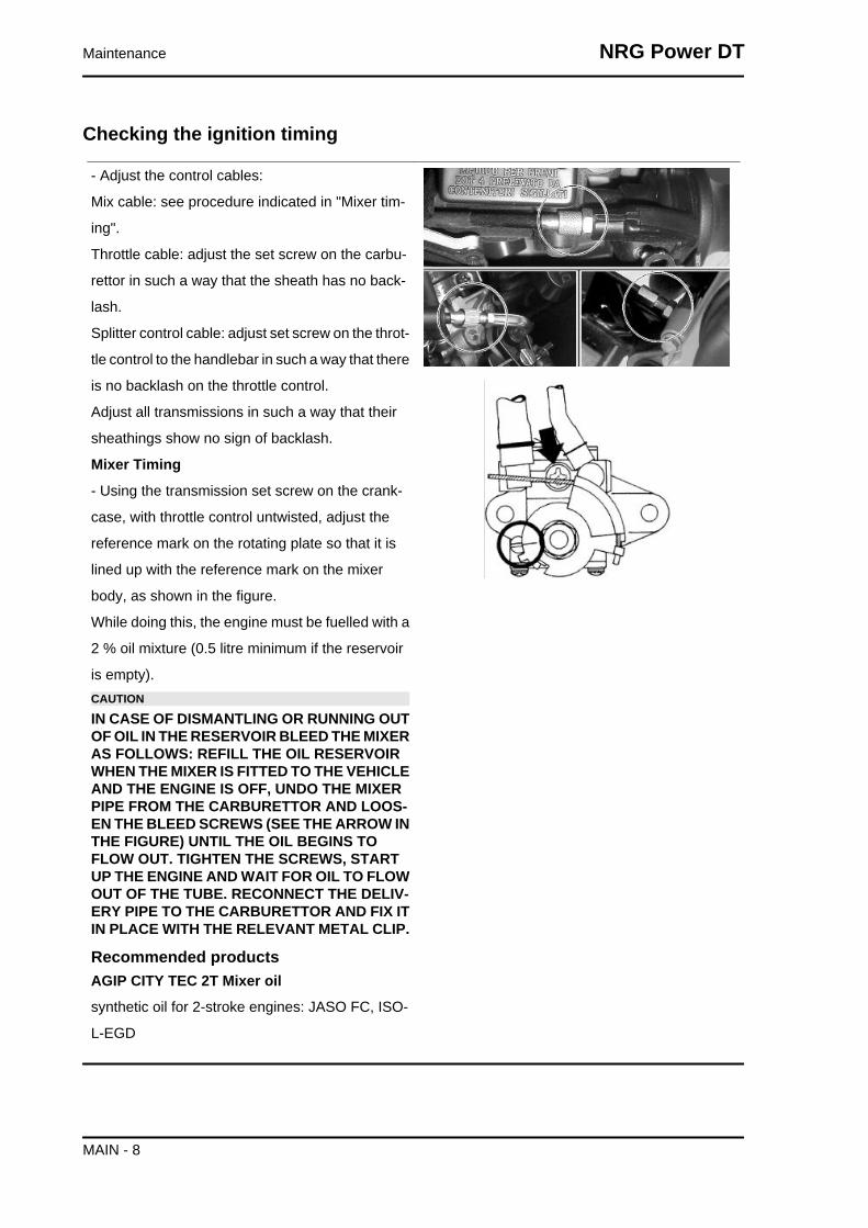
Mixer Timing
- Using the transmission set screw on the crank-
case, with throttle control untwisted, adjust the
reference mark on the rotating plate so that it is
lined up with the reference mark on the mixer
body, as shown in the figure.
While doing this, the engine must be fuelled with a
2 % oil mixture (0.5 litre minimum if the reservoir
is empty).CAUTION
IN CASE OF DISMANTLING OR RUNNING OUTOF OIL IN THE RESERVOIR BLEED THE MIXERAS FOLLOWS: REFILL THE OIL RESERVOIRWHEN THE MIXER IS FITTED TO THE VEHICLEAND THE ENGINE IS OFF, UNDO THE MIXERPIPE FROM THE CARBURETTOR AND LOOS-EN THE BLEED SCREWS (SEE THE ARROW INTHE FIGURE) UNTIL THE OIL BEGINS TOFLOW OUT. TIGHTEN THE SCREWS, STARTUP THE ENGINE AND WAIT FOR OIL TO FLOWOUT OF THE TUBE. RECONNECT THE DELIV-ERY PIPE TO THE CARBURETTOR AND FIX ITIN PLACE WITH THE RELEVANT METAL CLIP.
Recommended productsAGIP CITY TEC 2T Mixer oil
synthetic oil for 2-stroke engines: JASO FC, ISO-
L-EGD
Maintenance NRG Power DT
MAIN - 8
Braking system
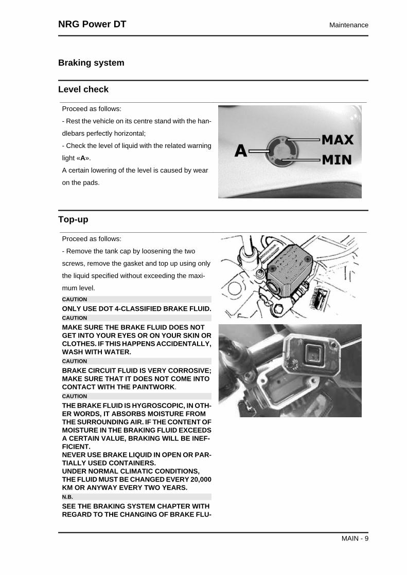
Level check
Proceed as follows:
- Rest the vehicle on its centre stand with the han-
dlebars perfectly horizontal;
- Check the level of liquid with the related warning
light «A».
A certain lowering of the level is caused by wear
on the pads.
Top-up
Proceed as follows:
- Remove the tank cap by loosening the two
screws, remove the gasket and top up using only
the liquid specified without exceeding the maxi-
mum level.CAUTION
ONLY USE DOT 4-CLASSIFIED BRAKE FLUID.CAUTION
MAKE SURE THE BRAKE FLUID DOES NOTGET INTO YOUR EYES OR ON YOUR SKIN ORCLOTHES. IF THIS HAPPENS ACCIDENTALLY,WASH WITH WATER.CAUTION
BRAKE CIRCUIT FLUID IS VERY CORROSIVE;MAKE SURE THAT IT DOES NOT COME INTOCONTACT WITH THE PAINTWORK.CAUTION
THE BRAKE FLUID IS HYGROSCOPIC, IN OTH-ER WORDS, IT ABSORBS MOISTURE FROMTHE SURROUNDING AIR. IF THE CONTENT OFMOISTURE IN THE BRAKING FLUID EXCEEDSA CERTAIN VALUE, BRAKING WILL BE INEF-FICIENT.NEVER USE BRAKE LIQUID IN OPEN OR PAR-TIALLY USED CONTAINERS.UNDER NORMAL CLIMATIC CONDITIONS,THE FLUID MUST BE CHANGED EVERY 20,000KM OR ANYWAY EVERY TWO YEARS.N.B.
SEE THE BRAKING SYSTEM CHAPTER WITHREGARD TO THE CHANGING OF BRAKE FLU-
NRG Power DT Maintenance
MAIN - 9

ID AND THE BLEEDING OF AIR FROM THECIRCUITS.
Recommended productsAGIP BRAKE 4 Brake fluid
FMVSS DOT 4 Synthetic fluid
Headlight adjustment
Proceed as follows:
1. Place the vehicle in running order and with the
tyres inflated to the prescribed pressure, on a flat
surface 10 m away from a white screen situated in
a shaded area, making sure that the longitudinal
axis of the vehicle is perpendicular to the screen;
2. Turn on the headlight and check that the bor-
derline of the projected light beam on the screen
is not lower than 9/10 of the distance from the
ground to the centre of vehicle headlamp and high-
er than 7/10;
3. Otherwise, regulate the headlight by adjusting
the screw «A», after removing the front grille.N.B.
THE ABOVE PROCEDURE COMPLIES WITHTHE EUROPEAN STANDARDS REGARDINGMAXIMUM AND MINIMUM HEIGHT OF LIGHTBEAMS. REFER TO THE STATUTORY REGU-LATIONS IN FORCE IN EVERY COUNTRYWHERE THE vehicle IS USED.
CO check
In the event that the exhaust on the vehicle being
tested does not have an exhaust gases collection
port, proceed as follows:
- Remove the R.H. side fairing
- Remove the secondary air box cover with the
aluminium cap by acting upon the clamp shown in
the figure.
Maintenance NRG Power DT
MAIN - 10

Attach the exhaust gas collection tube to the sec-
ondary air rubber manifold. Such joint must be
sealed in order to guarantee accurate CO read-
ings.
- Start the engine, adjust the idle speed to 1,700 ± 100 rpm and check the CO value is equal 3.5 ± 1%
- If the parameters found do not agree with the above figures, act upon the idle adjusting screw. Oth-
erwise, check the automatic choke device
Specific tooling020320Y Exhaust gases analyser
020332Y Digital rev counter
The check must be carried out after having care-
fully cleaned all carburettor components, with the
air filter clean, and the spark plug in good condi-
tions.
- Remove the R.H. side fairing
- Warn-up the engine by riding the vehicle on the
road for at least 10 minutes
- Shut down the engine
- Remove the 2 secondary air box screws shown
in the figure
− Place a plastic sheet between the one-way valve
and the aluminium outlet as shown in the figure
NRG Power DT Maintenance
MAIN - 11

− Ensure the one-way valve packing properly
seals the aluminium outlet fitting.
− Refit the aluminium outlet onto the SAS box as
shown in the picture.
- Attach the special tool and move the joints as
shown in the figure.
- Start the engine, adjust the idle speed to 1,700 ±
100 rpm and check the CO value is equal 3.5 ± 1%
- If the parameters found do not agree with the
above figures, act upon the idle adjusting screw.
Otherwise, check the automatic choke device.
Specific tooling020320Y Exhaust gases analyser
020332Y Digital rev counter
020625Y Kit for sampling gas from the exhaustmanifold
Maintenance NRG Power DT
MAIN - 12

INDEX OF TOPICS
TROUBLESHOOTING TROUBL

This section makes it possible to find the solutions to use in troubleshooting.
For each breakdown, a list of the possible causes and respective interventions is given.
Engine
Poor performance
POOR PERFORMANCEPossible Cause Operation
Defective fuel pump or damaged depression line Replace the pump or control linesCarburettor nozzles clogged or dirty Dismantle, wash with solvent and dry with com-
pressed airFuel filter on the tank outlet fitting dirty or clogged Clean the fitting filterExcess of encrustations in the combustion cham-
berRemove the encrustations
Lack of compression wear of the piston rings orcylinder
Check the worn parts and replace them
Exhaust pipe clogged due to excessive encrusta-tions
Replace the exhaust pipe and check the carbura-tion and mixer timer
Air filter blocked or dirty Clean according to the procedureStarter inefficient (stays on) Check the mechanical sliding, continuity of the cir-
cuit, the presence of power and electrical wiringClutch slipping Check the centrifugal brake shoe assembly and /
or clutch bell and replace if necessaryDefective mobile pulley sliding Check the parts, change the faulty parts and lubri-
cate the driven pulley using only Montblanc-Mo-libdenum Grease (dis. 498345) grease
Transmission belt worn ReplaceRoller wear; Presence of oil; Dirt Clean the speed variator, replace the rollers if worn
out
Rear wheel spins at idle
REAR WHEELPossible Cause Operation
Idling rpms too high Check the idling speed and, if necessary, adjustthe C.O.
Clutch fault Check the spring/friction mass and the clutch bellAir filter housing not sealed Correctly refit the filter housing and replace it if it
is damaged
Starting difficulties
DIFFICULTY STARTINGPossible Cause Operation
Carburettor nozzles clogged or dirty Dismantle, wash with solvent and dry with com-pressed air
Defective fuel pump or damaged depression line Replace the pump or control lines
Troubleshooting NRG Power DT
TROUBL - 2

Possible Cause OperationStarter inefficient Check: electric wiring, circuit continuity, mechani-
cal sliding and power supplyBattery flat Check the state of the battery. If it shows signs of
sulphation replace it and bring the new battery intoservice charging it for eight hours at a current of
1/10 of the capacity of the battery itself- Engine flooded. Start up keeping the throttle fully open alternating
approximately five seconds of turning it with fiveseconds still. If however it does not start, removethe spark plug, the engine over with the throttle
open being careful to keep the cap in contact withthe spark plug and the spark plug grounded but
away from its hole. Refit a dry spark plug and startthe vehicle.
Altered fuel characteristics Drain off the fuel no longer up to standard; then,refill
Defective spark plug or with incorrect electrodegap
Remove the encrustation, restore the plug gap orreplace being sure to use the types of spark plugrecommended at all times. Bear in mind that manyproblems engines have, derive from the use of the
wrong spark plugIntake joint cracked or with a bad seal Replace the intake joint and check its tightness on
the crankcase and on the carburettorPurifier-carburettor fitting damaged Replace
Excessive oil consumption/Exhaust smoke
EXCESSIVE OIL CONSUMPTION/SMOKEY EXHAUSTPossible Cause Operation
Excess of encrustations in the combustion cham-ber
Remove the encrustations
Engine tends to cut-off at full throttle
ENGINE STOP FULL THROTTLEPossible Cause Operation
Maximum nozzle dirty - lean mixture Wash the nozzle with solvent and dry with com-pressed air
Dirty carburettor Wash the carburettor with solvent and dry withcompressed air
Water in the carburettor Empty the tank through the appropriate bleed nip-ple.
Air filter dirty Clean or replaceDefective floating valve Check the proper sliding of the float and the func-
tioning of the valveTank breather hole obstructed Restore the proper tank aeration
NRG Power DT Troubleshooting
TROUBL - 3

Engine tends to cut-off at idle
ENGINE STOP IDLINGPossible Cause Operation
Minimum nozzle dirty Wash the nozzle with solvent and dry with com-pressed air
Starter that stays open Check: electric wiring, circuit continuity, mechani-cal sliding and power supply
Reed valve does not close Check / replace the reed packWrong idling adjustment Correctly adjust the engine idling and check the
level of the C.O.Spark plug defective or faulty Replace the spark plug with one with the specified
degree and check the plug gap
Excessive exhaust noise
INCREASED NOISINESSPossible Cause Operation
Secondary metal air pipe deteriorated Check the seal of the piping on the crankcase andon the housing, check the piping between the
housing and the muffler.Good condition of the missing secondary air circuit
componentsCheck the individual components and the piping,check the precision of the fitting. Replace the dam-
aged components
High fuel consumption
HIGH FUEL CONSUMPTIONPossible Cause Operation
Air filter blocked or dirty. Clean according to the procedureStarter inefficient Check: electric wiring, circuit continuity, mechani-
cal sliding and power supply
SAS malfunctions
SLACKENING OF THE RUBBER JOINT OF THE SECONDARY AIR PIPE ON THE MUF-FLER
Possible Cause OperationSecondary air reed blocking ReplaceSecondary air filter clogging Clean the filter and the housing
Blockage of the secondary air fitting on the muffler Remove the encrustations from the joint beingcareful not to let the debris fall into the muffler
Transmission and brakes
Troubleshooting NRG Power DT
TROUBL - 4

Clutch grabbing or performing inadequately
CLUTCHPossible Cause Operation
Tear or irregular functioning Check that the masses open and return normallyCheck that there is no grease on the masses
Check that the clutch masses' contact surface withthe clutch bell is mainly in the middle with charac-
teristics equivalent on the three massesCheck that the clutch bell is not scored or worn
abnormallyNever operate the engine without the clutch bell
Insufficient braking
BRAKING SYSTEM MALFUNCTIONPossible Cause Operation
Poor braking The rear (drum type) brake is adjusted by regulat-ing the special adjustment (on the wheel) bearingin mind that, with the control levers in the rest po-
sition, the wheels must turn freely.The braking action should begin when the brake
levers are pressed by about a third.Check the brake pad wear.
If it is not possible to remove any problems by sim-ply adjusting the transmissions, check the brake
pads and front brake disc, the brake shoes and therear drum. If you encounter excessive wear orscoring, make the necessary replacements.
Air bubbles inside the hydraulic braking system Carefully bleed the hydraulic braking system,(there must be no flexible movement of the brake
lever).Fluid leakage in hydraulic braking system Elastic fittings, piston seals or brake pump break-
down, replaceThe brake fluid has lost its properties Replace the front brake fluid and top up to the cor-
rect level in the pumpDefective sliding of the cables in their sheathes Lubricate or substitute
Brake noise Check the wear of the brake pads and/or shoes
Brakes overheating
BRAKES OVERHEATINGPossible Cause Operation
Defective piston sliding Check calliper and replace any damaged part.Brake disc or drum deformed Using a dial gauge, check the planarity of the disk
with the wheel correctly fitted or the concentricityof the rear drum.
Electrical system
NRG Power DT Troubleshooting
TROUBL - 5

Battery
BATTERYPossible Cause Operation
Battery The battery is the electrical device in the systemthat requires the most frequent inspections andthorough maintenance. If the vehicle is not used
for some time (1 month or more) the battery needsto be recharged periodically. The battery runs
down completely in the course of 5 ÷ 6 months. Ifthe battery is fitted on a motorcycle, be careful notto invert the connections, keeping in mind that theblack ground wire is connected to the negative ter-minal while the red wire is connected to the termi-nal marked+. Follow the instructions in the ELEC-TRICAL SYSTEM chapter for the recharging of the
batteries.
Steering and suspensions
Rear wheel
POOR ROAD HOLDINGPossible Cause Operation
Faulty suspension Check that the rear shock absorber and/or thefront fork is/are in good working order. Replace or
overhaul the front fork and/or replace the rearshock absorbers in case of malfunction
Tyres deflated or damaged Check the correct pressure of the tyres and thecondition of the tread. Inflate to the correct pres-
sure or replace.Loosen the anchorage points of the front and/or
rear suspension unit.Check the tightness between the frame, swingingarm and engine and the fixing of the wheels to thehub and/or the axle. Check the correct tightening
of the steering ring nut.
Heavy steering
STEERING HARDENINGPossible Cause Operation
Torque not conforming Check the tightening of the top and bottom ringnuts.
If irregularities continue in turning the steeringeven after making the above adjustments, checkthe seats in which the ball bearings rotate: replace
if they are recessed.
Troubleshooting NRG Power DT
TROUBL - 6

Excessive steering play
EXCESSIVE STEERING CLEARANCEPossible Cause Operation
EXCESSIVE STEERING CLEARANCE Check the tightening of the top and bottom ringnuts.
If irregularities continue in turning the steeringeven after making the above adjustments, checkthe seats in which the ball bearings rotate: replace
if they are recessed.
Noisy suspension
NOISY SUSPENSIONPossible Cause Operation
Components of the front suspension damaged. Check the quiet operation in the compression orrelease phases of the fork and if necessary over-
haul it. Check that there is no noise or seizingduring the wheel rotation; if there is, change the
wheel bearing.Components of the rear suspension damaged. Check the absence of noise in the compression or
release of the suspension, if necessary check theproper tightness to the swinging arm unit and theabsence of rust or replace the entire shock ab-sorber. Check that there is no noise or seizing
during the wheel rotation; if there is noise or seiz-ing overhaul the final reduction assembly.
Suspension oil leakage
OIL LEAKAGE FROM SUSPENSIONPossible Cause Operation
Shock absorbers malfunctioning Replace the complete shock absorption unitHydraulic cartridge in the fork damaged. Replace the hydraulic cartridge
NRG Power DT Troubleshooting
TROUBL - 7

Troubleshooting NRG Power DT
TROUBL - 8

INDEX OF TOPICS
ELECTRICAL SYSTEM ELE SYS

LEGENDSpecification Desc./Quantity
1 Voltage regulator2 Horn button3 Turn signal switch4 Light switch5 Rear brake stop button6 Front L.H. turn signal light7 Front headlight8 Two rear parking light bulbs 12V - 3W9 Horn10 Light bulb 12V - 35W for high-beam lamp11 Light bulb 12V - 35W for low-beam lamp12 Front R.H. turn signal light13 Front brake stop light switch14 Wheel rpm sensor15 Starter button16 Ignition key-switch17 Fuel level sender
Electrical system NRG Power DT
ELE SYS - 2

Specification Desc./Quantity18 Mixture oil warning light switch19 Starter remote control20 Magneto flywheel21 Control device ignition22 Automatic starter23 Starter motor24 Taillight resistor25 Rear R.H. turn signal light26 Taillight assembly27 Choke device continuity check light28 Battery 12V - 4Ah29 Rear L.H. turn signal light30 License plate light pre-wiring31 Fuse 7,5A32 Carburettor heater33 Carburettor heater control device
Electrical cables color:
B = White, Bl = Blu, G = Yellow, Mr = Brown, N = Black, Gr = Gray,
Rs = Pink, R = Red, Vi = Purple, V = Green
Conceptual diagrams
Ignition
IGNITIONSpecification Desc./Quantity
1 Electronic control unit2 Magneto flywheel
NRG Power DT Electrical system
ELE SYS - 3

Specification Desc./Quantity3 Pick - up4 Key switch5 Spark plug
Headlights and automatic starter section
HEADLIGHTS AND AUTOMATIC STARTER SECTIONSpecification Desc./Quantity
1 Flywheel magneto2 Voltage regulator3 Automatic starter4 LED taillight5 Digital instrument unit6 Headlamp sidelight bulbs7 Headlamp low-beam light bulb8 Headlamp high-beam light bulb9 Heating control device10 Carburettor heater
Electrical system NRG Power DT
ELE SYS - 4

Battery recharge and starting
BATTERY RECHARGE AND STARTINGSpecification Desc./Quantity
1 Flywheel magneto2 Voltage regulator3 Fuse 7,5A4 Battery 12V-14Ah5 Starter remote control6 Starter motor7 LED taillight8 Ignition key-switch9 Start up button10 Stoplight switches11 Mixture oil level sender
NRG Power DT Electrical system
ELE SYS - 5

Level indicators and enable signals section
SAFETY SWITCHES AND LEVEL GAUGESSpecification Desc./Quantity
1 Voltage regulator2 Ignition key-switch3 Fuse 7,5A4 Battery 12V-14Ah5 Starter button6 Starter remote control7 Starter motor8 Stoplight switches9 Fuel level sender10 Coolant temperature sensor11 Mixture oil level sender12 Phonic wheel13 Digital instrument unit
Electrical system NRG Power DT
ELE SYS - 6

Turn signal lights
TURN SIGNALS AND HORNSpecification Desc./Quantity
1 Voltage regulator2 Ignition key-switch3 Fuse 7,5A4 Battery 12V-14Ah5 Horn button6 Horn7 Turn signal lights8 Turn signal switch9 Digital instrument unit
Digital instrument panel
DASHBOARD CONNECTORSpecification Desc./Quantity
1 + Battery2 + permanent power supply3 Earth4 Grounding for phonic wheel5 Power supply to phonic wheel6 Phonic wheel signal7 Instrument light and parking light indicator8 Not connected (temperature tool earth)9 Not connected10 Rpm indicator signal11 Not connected (temperature tool signal)12 Fuel level sensor13 High-beam warning light
NRG Power DT Electrical system
ELE SYS - 7

Specification Desc./Quantity14 + Right direction indicator15 + Left direction indicator16 Low-oil warning light17 Low-fuel warning light18 Not connected19 Not connected20 Not connected
Checks and inspections
Checks to be made in the case of ignition ir-
regularities and/or no spark on the spark plug
1. Check the condition of the spark plug (clean
it with a metal brush, remove the encrusta-
tions, blast it with compressed air and, if
necessary, replace it).
2. Without removing the stator, carry out the
following checks:
CHECK ON THE PICK UPSpecification Desc./Quantity
1 Red and white cable 90±140 ohm
After visually checking the electrical wiring, per-
form measurements on the loading reel, the pickup
(see chart) and the continuity using the appropri-
ate tester.
If checks on the loading reel, pickup and continuity
show abnormalities, replace the stator; otherwise
replace the central unit. Remember that discon-
nections due to replacement of the central unit
must be done with the engine off.
Specific tooling
Electrical system NRG Power DT
ELE SYS - 8

020331Y Digital multimeter
CHECKING THE RECHARGE COILSpecification Desc./Quantity
1 White/green cable 800±1100 ohm
CHECK CONTINUITYSpecification Desc./Quantity
1 White cable-frame continuity2 White cable-engine continuity
Ignition circuit
All the control operations of the system that require
the disconnection of cables (checks of the con-
nections and the devices making up the ignition
circuit) must be done with the engine off: if this is
not done, the controls might be irreparably dam-
aged.
Stator check
- Using a tester, check the resistance between the
brown-earth and black-earth terminal.N.B.
VALUES ARE STATED AT AMBIENT TEMPER-ATURE. A CHECK WITH THE STATOR AT OP-ERATING TEMPERATURE LEADS TO VALUESHIGHER THAN THOSE STATED.
Electric characteristicStator : Brown-earth
approx. 170 Ω (Pick-Up)
Stator : Black-earth
~ 1 Ω (Stator)
Voltage regulator check
The fault to the voltage regulator may cause, according to the type of fault, the following inconvenients:
1. Bursting of head and taillight bulbs.
2. Head and taillight not operational.
3. Excessive battery recharge (bursting of main fuse).
NRG Power DT Electrical system
ELE SYS - 9

4. Battery not recharging.
5. Turn signals not operational.
6. Dashboard check not operational.
Interventions
FAULT 1
Replace the regulator as definitely faulty.
FAULT 2
a) Check the output from the stator gives the cor-
rect voltage: detach the stator connector, inter-
pose an AC tester between the grey-blue and
black cables, and check the output voltage is with-
in the prescribed limits. If anomalies are found,
replace the stator.
b) If no anomalies are identified, replace the reg-
ulator.
c) If the replacement of the regulator does not
solve the fault, check the electric connections.
Specific tooling020331Y Digital multimeter
CharacteristicVoltage distributed at 3000 rpms
25 to 30V
FAULT 3
After checking that there are no short circuits in the
system towards the earth, replace the regulator
because it is certainly inefficient and replace it with
a protective fuse.
Following the replacement, measure the current
and the recharging voltage on the battery end.
Electrical system NRG Power DT
ELE SYS - 10

FAULT 4
a) Interposing the AC tester between the black and
yellow cables on the regulator, check the genera-
tor output voltage is within the prescribed values
(this measurement must be carried out with the
battery detached). In the event of anomalies, re-
place the stator; otherwise proceed to point b).
b) Insert an ammeter between the stator (blue ca-
ble) and the battery and check with the tester that
the current output, at 3,000 rpm and with the bat-
tery kept between 12 and 13V, is as shown. If the
values thus obtained are lower than prescribed,
proceed by replacing the regulator.N.B.
BEFORE CARRYING OUT THE CHECKS ONTHE REGULATOR AND RELATIVE SYSTEM, ITIS ALWAYS GOOD PRACTICE TO CHECKTHAT THERE IS CONTINUITY BETWEEN THEBLACK CABLE AND THE GROUND.N.B.
TO KEEP THE BATTERY BETWEEN 12 AND13V, CAUSING CURRENT ABSORPTION BYTHE SYSTEM, A 12V - 35W BULB CONNECTEDBETWEEN THE + BATTERY AND GROUNDCAN BE USED.
Specific tooling020331Y Digital multimeter
CharacteristicVoltage output at 300 rpm
26÷30V
Distributed current
1.5 to 2A
FAULT 5
In the event that the turn signal lights are not op-
erational, proceed as follows:
• Remove the regulator connector and
insert the tester terminals between pin
5 and ground.
• Turn the ignition switch onto ON and
check for battery voltage. If no voltage
NRG Power DT Electrical system
ELE SYS - 11
is found, check wiring and terminals on
key-switch and battery.
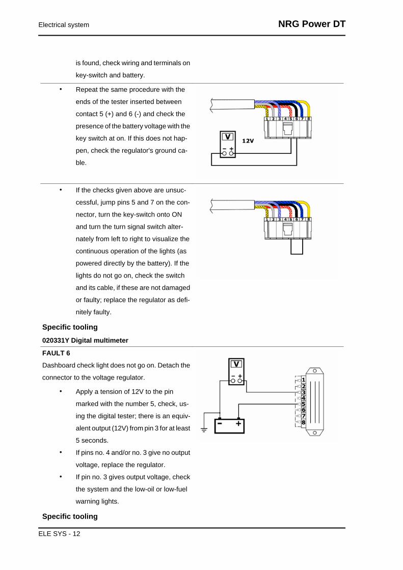
• Repeat the same procedure with the
ends of the tester inserted between
contact 5 (+) and 6 (-) and check the
presence of the battery voltage with the
key switch at on. If this does not hap-
pen, check the regulator's ground ca-
ble.
• If the checks given above are unsuc-
cessful, jump pins 5 and 7 on the con-
nector, turn the key-switch onto ON
and turn the turn signal switch alter-
nately from left to right to visualize the
continuous operation of the lights (as
powered directly by the battery). If the
lights do not go on, check the switch
and its cable, if these are not damaged
or faulty; replace the regulator as defi-
nitely faulty.
Specific tooling020331Y Digital multimeter
FAULT 6
Dashboard check light does not go on. Detach the
connector to the voltage regulator.
• Apply a tension of 12V to the pin
marked with the number 5, check, us-
ing the digital tester; there is an equiv-
alent output (12V) from pin 3 for at least
5 seconds.
• If pins no. 4 and/or no. 3 give no output
voltage, replace the regulator.
• If pin no. 3 gives output voltage, check
the system and the low-oil or low-fuel
warning lights.
Specific tooling
Electrical system NRG Power DT
ELE SYS - 12

020331Y Digital multimeter
Fuses
The electrical system is protected by a fuse loca-
ted on the r.h.s. of the battery bay. To replace it,
lift the seat, remove the battery access door and
then the transparent fuse cover. Ignition system,
headlight, and taillight are not protected by the
fuses.CAUTION
BEFORE REPLACING THE BLOWN FUSE,SEARCH AND ELIMINATE THE BREAKDOWNTHAT HAS LED TO THE BLOW OUT.NEVER TRY TO REPLACE A FUSE USING DIF-FERENT MATERIAL (FOR EXAMPLE A PIECEOF ELECTRIC WIRE) OR A FUSE FOR A HIGH-ER AMPERAGE THAN THE INDICATED ONE.
Electric characteristicFuse
7.5 A
Sealed batteryCommissioning of sealed battery
INSTRUCTIONS FOR REFRESHING THE STOCK CHARGE OF AN OPEN CIRCUIT
1) Voltage check
Before installing the battery on the vehicle, check the open circuit voltage with a normal tester.
- If the voltage exceeds 12.60 V, the battery may be installed without any renewal recharge.
- If voltage is below 12.60 V, a renewal recharge is required as explained in 2).
2) Constant voltage battery charge mode
-Constant voltage equal to 14.40÷14.70V
-Initial charge voltage equal to 0.3÷0.5 for nominal capacity
-Duration of the charge: 10 to 12 h recommended
Minimum 6 h
Maximum 24 h
3) Constant current battery charge mode
-Charge current equal to 1/10 of the nominal capacity of the battery
-Duration of the charge: 5 hWARNING
-WHEN THE BATTERY IS REALLY FLAT (WELL BELOW 12.6V) IT MIGHT BE THAT 5 HOURS OFRECHARGING ARE NOT ENOUGH TO ACHIEVE OPTIMAL PERFORMANCE.
NRG Power DT Electrical system
ELE SYS - 13

IN THESE CONDITIONS IT IS HOWEVER ESSENTIAL NOT TO EXCEED EIGHT HOURS OF CON-TINUOUS RECHARGING SO AS NOT TO DAMAGE THE BATTERY ITSELF.
Dry-charge batteryWARNING
THE BATTERY ELECTROLYTE IS POISONOUS AS IT MAY CAUSE SERIOUS BURNS. IT CON-TAINS SULPHURIC ACID. AVOID CONTACT WITH THE EYES, THE SKIN AND CLOTHING. IFCOMING INTO CONTACT WITH EYES OR SKIN, WASH ABUNDANTLY WITH WATER FOR AP-PROX. 15 MIN. AND SEEK IMMEDIATE MEDICAL ATTENTION.IN THE EVENT OF ACCIDENTAL INGESTION OF THE LIQUID, IMMEDIATELY DRINK LARGEQUANTITIES OF WATER OR MILK, MAGNESIUM MILK, BATTERED EGG OR VEGETABLE OIL.SEEK IMMEDIATE MEDICAL ATTENTION.THE BATTERIES PRODUCE EXPLOSIVE GAS; KEEP CLEAR OF NAKED FLAMES, SPARKS ORCIGARETTES; VENTILATE THE AREA WHEN RECHARGING INDOORS.ALWAYS WEAR EYE PROTECTION WHEN WORKING IN THE PROXIMITY OF BATTERIES.KEEP OUT OF REACH OF CHILDREN
Use of dry-cell batteries :
1. Having removed the short, closed tube and removed the caps, put into the elements sulphuric
acid of the type for specific weight 1.26 accumulators corresponding to 30° Bé at a temperature
of no less than 15°, until you reach the upper level.
2. Leave to stand for at least 2 hours; afterwards top-up to the level with sulphuric acid.
3. Within twenty four hours, recharge with the special (single or multiple) battery charger that re-
charges at an intensity the same as approximately 1/10 the rated capacity of the said battery. At
the end of the charge, make sure that the density of the acid is around 1.27, corresponding to 31°
Bé and that these values are stabilised.
4. Once the charge is over, level the acid (by adding distilled water). Close and clean carefully.
5. Once the above operations have been performed, install the battery in the vehicle ensuring that
it is wired up properly..WARNING
- ONCE THE BATTERY HAS BEEN INSTALLED IN THE VEHICLE IT IS NECESSARY TO REPLACETHE SHORT TUBE (WITH CLOSED END) NEAR THE + POSITIVE TERMINAL WITH THE CORRE-SPONDING LONG TUBE (WITH OPEN END), THAT YOU FIND FITTED TO THE VEHICLE, TOENSURE THAT THE GASES THAT FORM CAN ESCAPE PROPERLY.
Specific tooling020333Y Single battery charger
020334Y Multiple battery charger
Electrical system NRG Power DT
ELE SYS - 14

1 Hold the vertical tube
2 Look at the level
3 The float must be freed
Battery maintenance
The battery is an electrical device which requires careful monitoring and diligent maintenance. The
maintenance rules are:
1) Check the level of the electrolyte
The electrolyte level must be checked frequently and must reach the upper level. Only use distilled
water, to restore this level. If it is necessary to add water too frequently, check the vehicle's electrical
system: the battery works overcharged and is subject to quick wear.
2)Load status check
After restoring the electrolyte level, check its density using an appropriate densitometer (see the figure).
When the battery is charged, you should detect a density of 30 to 32 Bé corresponding to a specific
weight of 1.26 to 1.28 at a temperature of no lower than 15° C.
A density reading of less than 20° Bé indicates that the battery is completely flat and it must therefore
be recharged.
If the scooter is not used for a given time (1 month or more) it will be necessary to periodically recharge
the battery.
The battery runs down completely in the course of three months. If it is necessary to refit the battery in
the vehicle, be careful not to reverse the connections, remembering that the ground wire (black) marked
(-) must be connected to the -negative clamp while the other two red wires marked (+) must be con-
nected to the clamp marked with the +positive sign.
3) Recharging the battery
Remove the battery from the vehicle removing the negative clamp first.
The normal bench charging must be carried out with the specific (single or multiple) battery charger,
placing the battery charger selector on the type of battery to be recharged. The connections to the power
supply must be made by connecting to the corresponding poles (+ with+ and -with -).
4) Battery cleaning
The battery should always be kept clean, especially on its top side, and the terminals should be coated
with Vaseline.WARNING
BEFORE RECHARGING THE BATTERY, REMOVE THE PLUGS OF EACH CELL. KEEP SPARKSAND NAKED FLAMES AWAY FROM THE BATTERY WHILE RECHARGING.CAUTION
NRG Power DT Electrical system
ELE SYS - 15

NEVER USE FUSES WITH A CAPACITY HIGHER THAN THE RECOMMENDED CAPACITY. USINGA FUSE OF UNSUITABLE RATING MAY SERIOUSLY DAMAGE THE VEHICLE OR EVEN CAUSEA FIRE.CAUTION
ORDINARY AND DRINKING WATER CONTAINS MINERAL SALTS THAT ARE HARMFUL FORTHE BATTERY. FOR THIS REASON, YOU MUST ONLY USE DISTILLED WATER.CAUTION
CHARGE THE BATTERY BEFORE USE TO ENSURE OPTIMUM PERFORMANCE. INADEQUATECHARGING OF THE BATTERY WITH A LOW LEVEL OF ELECTROLYTE BEFORE IT IS FIRSTUSED SHORTENS THE LIFE OF THE BATTERY.
Specific tooling020334Y Multiple battery charger
020333Y Single battery charger
Electrical system NRG Power DT
ELE SYS - 16

INDEX OF TOPICS
ENGINE FROM VEHICLE ENG VE

Removal of the engine from the vehicle
1. Detach the battery.
2. Remove the exhaust assy.
3. Remove the rear wheel.
4. Remove the rear brake cable.
5. Detach the electrical connection to the fly-
wheel.
6. Detach the throttle and mixer cables.
7. Detach the mixture oil, fuel, and vacuum
pump outlet tubing.
8. Detach the H.T. cable from the spark plug.
9. Remove the rear shock-absorber fixing bolt
from the engine.
10.Remove the nut on the l.h.s., and hence re-
move the engine - swing-arm fixing bolt.
Locking torques (N*m)Engine-swinging arm bolt 33 ÷ 41 Shock ab-sorber-engine pin 33 to 41 Nm Rear wheel axlenut 104 ÷ 126
Engine from vehicle NRG Power DT
ENG VE - 2

INDEX OF TOPICS
ENGINE ENG

Automatic transmission
Transmission cover
- Loosen the 15 screws and remove the transmis-
sion cover with the aid of a mallet.N.B.
THE CRANKCASE IS SLIGHTLY BLOCKED BYTHE TIGHT FIT BETWEEN THE SHAFT OF THEDRIVEN HALF-PULLEY AND THE BEARINGHOUSED ON THE CRANKCASE.
Kickstart
- Remove the seeger ring located on the exterior
of the crankshaft.
- Dismantle the dog gear from its seat, slackening
the tension that the toothed sector applies to it by
means of the spring; to do this, it is necessary to
rotate the toothed sector slightly (see the figure).CAUTION
WHILE REMOVING THE TOOTHED SECTOR,BE VERY CAREFUL OF THE SPRING TEN-SION: IT COULD CONSTITUTE A HAZARD FORTHE OPERATOR.
- Upon refitting, apply the recommended grease to
the bushing, to the spring and along the toothed
sector.
- Use the special tool for the charging of the spring,
as shown in the figure.
- Refit the seeger ring after checking that it is in
good condition.
Specific tooling020261Y Starter spring fitting
Recommended productsAGIP GREASE MU3 Grease for odometertransmission gear case
Engine NRG Power DT
ENG - 2

Soap-based lithium grease with NLGI 3; ISO-L-
XBCHA3, DIN K3K-20
- Remove the screws shown in the figure and re-
move the engine starting lever.
- For the assembly, work in reverse and tighten the
screws to the prescribed torque..
Locking torques (N*m)Starter lever replacement 12 to 13 Nm
Removing the driven pulley shaft bearing
- Slightly heat the crankshaft from the inside side
to avoid damaging the coated surface and use the
driven pulley shaft or a pin of the same diameter
to remove the bearing.N.B.
IN CASE OF DIFFICULTY A STANDARD 8MM-INSIDE DIAMETER EXTRACTOR CAN BEUSED.
Refitting the driven pulley shaft bearing
-Refit the bearing with the aid of a bushing with the same diameter as the external plate of the bearing
after slightly heating the crankcase from the inside.N.B.
WHEN REFITTING, ALWAYS REPLACE THE BEARING WITH A NEW ONE.CAUTION
WHEN REMOVING/REFITTING THE BEARING, TAKE CARE NOT TO DAMAGE THE PAINTEDSURFACE.
NRG Power DT Engine
ENG - 3

Removing the driven pulley
- Lock the clutch bell housing with the specific tool.
- Remove the nut, the clutch bell housing and the
whole of the driven pulley assembly.N.B.
THE UNIT CAN ALSO BE REMOVED WITH THEDRIVE PULLEY MOUNTED.
Specific tooling020565Y Flywheel lock calliper spanner
Inspecting the clutch drum
- Check that the clutch bell is not worn or damaged.
- Measure the inner diameter of the clutch bell.
CharacteristicClutch bell diameter/standard value
Ø 107+0.2 +0 mm
Clutch bell diameter/max. value allowed afteruse
Ø 107.5 mm
Eccentricity measured /max.
0.20 mm
Removing the clutch
- Equip the tool with long pins screwed into position
«A» from the outside, insert the entire driven pulley
in the tool and put the central screw under stress.CAUTION
THE TOOL WILL BE DEFORMED IF THE CEN-TRAL SCREW IS TIGHTENED UP TOO FAR.
Engine NRG Power DT
ENG - 4

- Using a 34 mm socket wrench remove the clutch
locking nut.
- Loosen the central screw thereby undoing the
driven pulley unit
- Separate the components.
Specific tooling020444Y Tool for fitting/ removing the drivenpulley clutch
Inspecting the clutch
- Check the thickness of the clutch mass friction
material.
- The masses must not show traces of lubricants;
otherwise, check the driven pulley unit seals.N.B.
UPON RUNNING-IN, THE MASSES MUST EX-HIBIT A CENTRAL CONTACT SURFACE ANDMUST NOT BE DIFFERENT FROM ONE AN-OTHER.VARIOUS CONDITIONS CAN CAUSE THECLUTCH TO TEAR.CAUTION
DO NOT OPEN THE MASSES USING TOOLSTO PREVENT A VARIATION IN THE RETURNSPRING LOAD.
CharacteristicCheck minimum thickness
1 mm
Pin retaining collar
- Remove the collar with the aid of 2 screwdrivers.
NRG Power DT Engine
ENG - 5

- Remove the three guide pins and the mobile half
pulley.
Removing the driven half-pulley bearing
- Remove the roller bearing with the special ex-
tractor inserted from the bottom of the fixed half-
pulley.CAUTION
POSITION THE HOLDING EDGE OF THE EX-TRACTION PLIERS BETWEEN THE END OFTHE BEARING AND THE BUILT IN SEALINGRING.
Specific tooling001467Y029 Bell for bearings, O.D. 38 mm
- Remove the ball bearing retention snap ring.
- Expel the ball bearing from the side of the clutch
housing by means of the special tool.N.B.
PROPERLY SUPPORT THE HALF-PULLEY SOAS NOT TO DEFORM THE SLIDING SURFACEOF THE DRIVING BELT
Specific tooling020376Y Adaptor handle
020363Y 20 mm guide
Engine NRG Power DT
ENG - 6

Inspecting the driven fixed half-pulley
- Check that there are no signs of wear on the work
surface of the belt. If there are, replace the half-
pulley..
- Make sure the bearings do not show signs of un-
usual wear.
- Measure the external diameter of the pulley bush-
ing.
CharacteristicStationary driven half-pulley/Standard diame-ter
Ø 33.965 to 33.985 mm
Stationary driven half-pulley / Minimum diam-eter admitted after use
Ø 33.96 mm
Inspecting the driven sliding half-pulley
- Remove the 2 inner sealing rings and the two O-
rings.
- Measure the inside diameter of the mobile half-
pulley bushing.
CharacteristicMobile driven half-pulley/ Maximum diameterallowed
Ø 34.08 mm
- Check the belt contact surfaces.
- Insert the new oil seal and O-rings on the mobile
half-pulley.
- Fitting the half-pulley on the bushing.
Recommended productsAGIP GREASE SM 2 Grease for the tone wheelrevolving ring
Soap-based lithium grease containing NLGI 2 Mo-
lybdenum disulphide; ISO-L-XBCHB2, DIN
KF2K-20
- Make sure the pins and collar are not worn, reassemble the pins and collar.
NRG Power DT Engine
ENG - 7

- Use a greaser with a curved spout to lubricate the driven pulley unit with around 6 gr. of grease. This
operation must be done through one of the holes inside the bushing until grease comes out of the
opposite hole. This procedure is necessary to prevent the presence of grease beyond the O-ring.
Recommended productsAGIP GREASE SM 2 Grease for the tone wheel revolving ring
Soap-based lithium grease containing NLGI 2 Molybdenum disulphide; ISO-L-XBCHB2, DIN KF2K-20
Refitting the driven half-pulley bearing
- Fit a new ball bearing with the specific tool.
- Fit the ball bearing retention snap ring.
- Fit the new roller bearing with the wording visible
from the outside.CAUTION
PROPERLY SUPPORT THE HALF-PULLEY TOPREVENT DAMAGE TO THE THREADED ENDWHILE THE BEARINGS ARE BEING FITTED.
Specific tooling020376Y Adaptor handle
020456Y Ø 24 mm adaptor
020362Y 12 mm guide
020171Y Punch for Ø 17 mm roller case
Inspecting the clutch spring
- Check that the contrast spring of the driven pulley
does not show signs of deformation
- Measure the free length of the spring
CharacteristicStandard length
118 mm
Minimum length allowed after use
XXXX
Engine NRG Power DT
ENG - 8

Refitting the clutch
- Preassemble the driven pulley group with spring,
sheath and clutch.
- Position the spring with the sheath
- Insert the components in the tool and preload the
spring being careful not to damage the plastic
sheath and the end of the threaded bar.
- Reassemble the nut securing the clutch and tight-
en to the prescribed torque.CAUTION
SO AS NOT TO DAMAGE THE CLUTCH NUTUSE A SOCKET WRENCH WITH SMALLCHAMFER.CAUTION
POSITION THE NON-CHAMFERED SURFACESOF THE NUT IN CONTACT WITH THE CLUTCH
Locking torques (N*m)Nut locking clutch unit on pulley 55 ÷ 60 Nm
Refitting the driven pulley
-Refit the driven pulley assembly, the clutch bell
and the nut, using the specific tool.
Specific tooling020565Y Flywheel lock calliper spanner
Locking torques (N*m)Driven pulley shaft nut 40 to 44 Nm
NRG Power DT Engine
ENG - 9

Drive-belt
- Make sure the driving belt is not damaged and
does not have cracks in the toothed grooves.
- Check the width of the belt.
CharacteristicTransmission belt/Minimum width
17.5 mm
Removing the driving pulley
- Lock the driving pulley using the appropriate tool.
- Remove the central nut with the related washer,
then remove the drive and the plastic fan.
- Remove the stationary half-pulley.
- Remove the belt, washer and remove the mobile half-pulley with its bushing, being careful that the
rollers and contrast plate fitted loosely on it do not come off.
Specific tooling020451Y Start-up crown lock
Mixer gears and belt
- Remove gear and belt.CAUTION
PAY PARTICULAR ATTENTION TO NOTTOUCHING OR BENDING THE BELT BE-CAUSE THIS COULD BREAK SUDDENLY DUR-ING OPERATION.CAUTION
ON REFITTING, MAKE SURE THAT DIRT DOESNOT GET INTO THE INNER BUSHING OF THEMIXER CONTROL GEAR AND THAT IT DOESNOT EXERT ANY STRESS ON THE CRANK-CASE PIN.N.B.
REPLACE THE BELT EVERY 20000 KM.
Engine NRG Power DT
ENG - 10
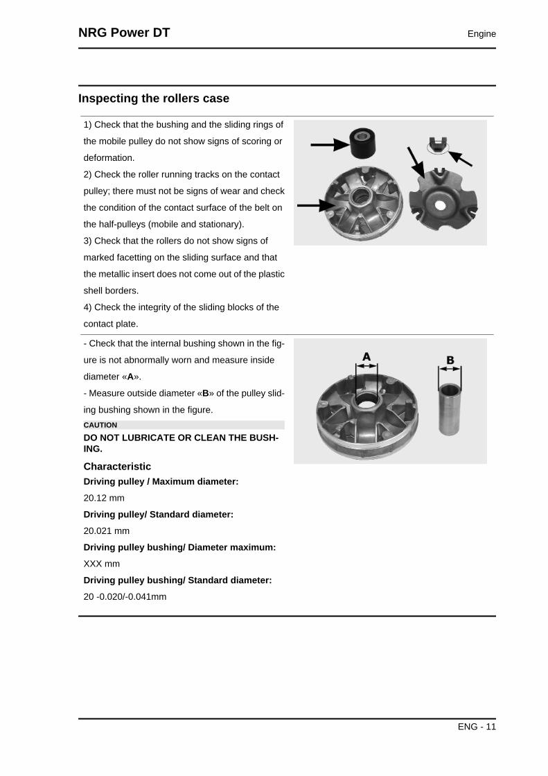
Inspecting the rollers case
1) Check that the bushing and the sliding rings of
the mobile pulley do not show signs of scoring or
deformation.
2) Check the roller running tracks on the contact
pulley; there must not be signs of wear and check
the condition of the contact surface of the belt on
the half-pulleys (mobile and stationary).
3) Check that the rollers do not show signs of
marked facetting on the sliding surface and that
the metallic insert does not come out of the plastic
shell borders.
4) Check the integrity of the sliding blocks of the
contact plate.
- Check that the internal bushing shown in the fig-
ure is not abnormally worn and measure inside
diameter «A».
- Measure outside diameter «B» of the pulley slid-
ing bushing shown in the figure.CAUTION
DO NOT LUBRICATE OR CLEAN THE BUSH-ING.
CharacteristicDriving pulley / Maximum diameter:
20.12 mm
Driving pulley/ Standard diameter:
20.021 mm
Driving pulley bushing/ Diameter maximum:
XXX mm
Driving pulley bushing/ Standard diameter:
20 -0.020/-0.041mm
NRG Power DT Engine
ENG - 11
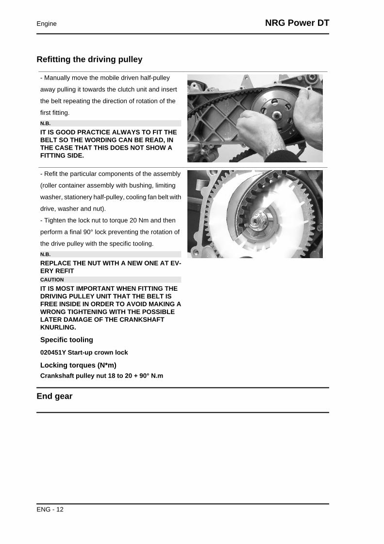
Refitting the driving pulley
- Manually move the mobile driven half-pulley
away pulling it towards the clutch unit and insert
the belt repeating the direction of rotation of the
first fitting.N.B.
IT IS GOOD PRACTICE ALWAYS TO FIT THEBELT SO THE WORDING CAN BE READ, INTHE CASE THAT THIS DOES NOT SHOW AFITTING SIDE.
- Refit the particular components of the assembly
(roller container assembly with bushing, limiting
washer, stationery half-pulley, cooling fan belt with
drive, washer and nut).
- Tighten the lock nut to torque 20 Nm and then
perform a final 90° lock preventing the rotation of
the drive pulley with the specific tooling.N.B.
REPLACE THE NUT WITH A NEW ONE AT EV-ERY REFITCAUTION
IT IS MOST IMPORTANT WHEN FITTING THEDRIVING PULLEY UNIT THAT THE BELT ISFREE INSIDE IN ORDER TO AVOID MAKING AWRONG TIGHTENING WITH THE POSSIBLELATER DAMAGE OF THE CRANKSHAFTKNURLING.
Specific tooling020451Y Start-up crown lock
Locking torques (N*m)Crankshaft pulley nut 18 to 20 + 90° N.m
End gear
Engine NRG Power DT
ENG - 12
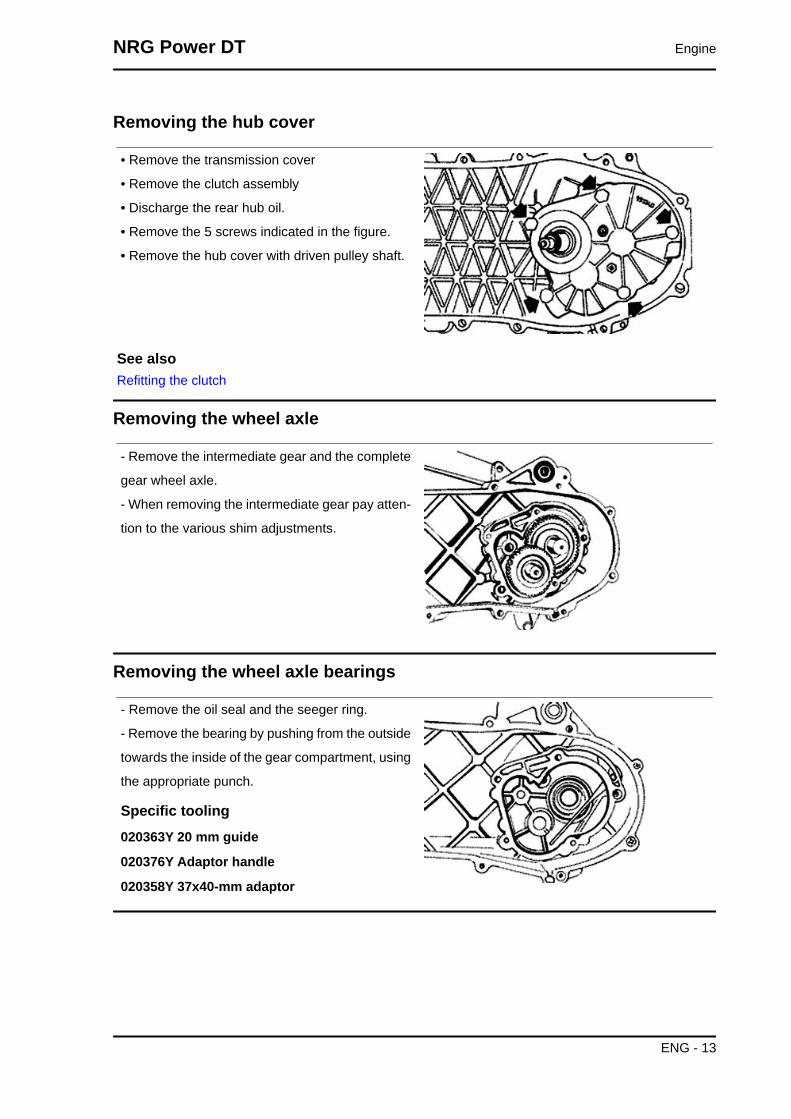
Removing the hub cover
• Remove the transmission cover
• Remove the clutch assembly
• Discharge the rear hub oil.
• Remove the 5 screws indicated in the figure.
• Remove the hub cover with driven pulley shaft.
See alsoRefitting the clutch
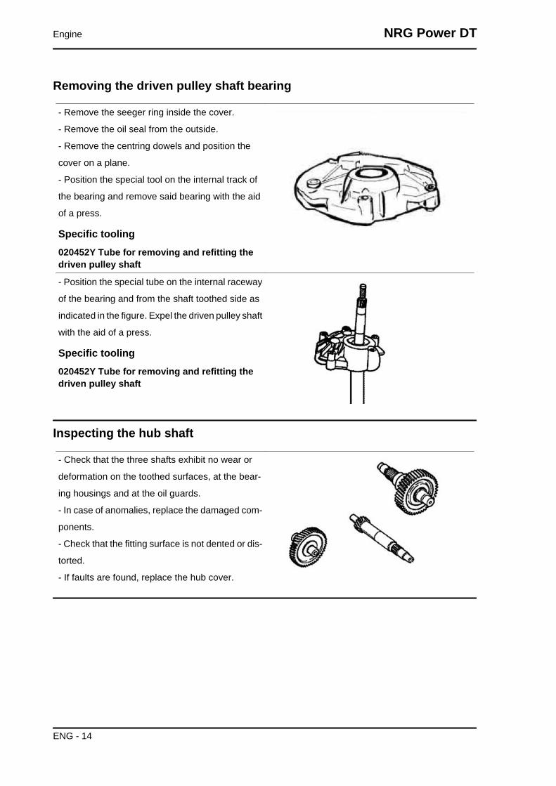
Removing the wheel axle
- Remove the intermediate gear and the complete
gear wheel axle.
- When removing the intermediate gear pay atten-
tion to the various shim adjustments.
Removing the wheel axle bearings
- Remove the oil seal and the seeger ring.
- Remove the bearing by pushing from the outside
towards the inside of the gear compartment, using
the appropriate punch.
Specific tooling020363Y 20 mm guide
020376Y Adaptor handle
020358Y 37x40-mm adaptor
NRG Power DT Engine
ENG - 13
Removing the driven pulley shaft bearing
- Remove the seeger ring inside the cover.
- Remove the oil seal from the outside.
- Remove the centring dowels and position the
cover on a plane.
- Position the special tool on the internal track of
the bearing and remove said bearing with the aid
of a press.
Specific tooling020452Y Tube for removing and refitting thedriven pulley shaft
- Position the special tube on the internal raceway
of the bearing and from the shaft toothed side as
indicated in the figure. Expel the driven pulley shaft
with the aid of a press.
Specific tooling020452Y Tube for removing and refitting thedriven pulley shaft
Inspecting the hub shaft
- Check that the three shafts exhibit no wear or
deformation on the toothed surfaces, at the bear-
ing housings and at the oil guards.
- In case of anomalies, replace the damaged com-
ponents.
- Check that the fitting surface is not dented or dis-
torted.
- If faults are found, replace the hub cover.
Engine NRG Power DT
ENG - 14
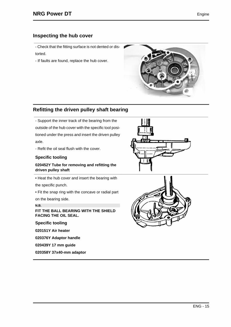
Inspecting the hub cover
- Check that the fitting surface is not dented or dis-
torted.
- If faults are found, replace the hub cover.
Refitting the driven pulley shaft bearing
- Support the inner track of the bearing from the
outside of the hub cover with the specific tool posi-
tioned under the press and insert the driven pulley
axle.
- Refit the oil seal flush with the cover.
Specific tooling020452Y Tube for removing and refitting thedriven pulley shaft
• Heat the hub cover and insert the bearing with
the specific punch.
• Fit the snap ring with the concave or radial part
on the bearing side.N.B.
FIT THE BALL BEARING WITH THE SHIELDFACING THE OIL SEAL.
Specific tooling020151Y Air heater
020376Y Adaptor handle
020439Y 17 mm guide
020358Y 37x40-mm adaptor
NRG Power DT Engine
ENG - 15
Refitting the wheel axle bearing
- Heat the half crankcase on the transmission side
using a thermal gun.
- After lubricating its outer strip, insert the bearing
with the special adapter with the aid of a hammer.
- Refit the seeger ring and the oil seal using the 42
x 47 mm adapter and the handle.
Specific tooling020151Y Air heater
020376Y Adaptor handle
020363Y 20 mm guide
020359Y 42x47-mm adaptor
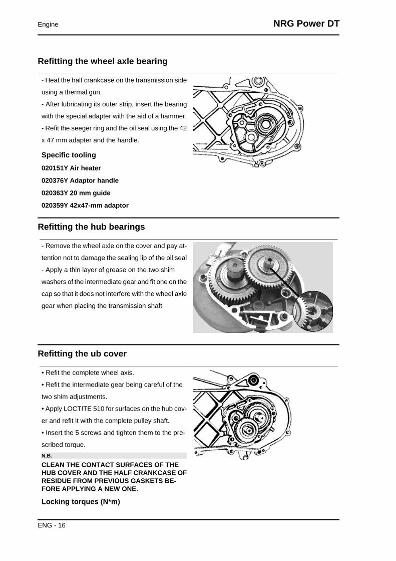
Refitting the hub bearings
- Remove the wheel axle on the cover and pay at-
tention not to damage the sealing lip of the oil seal
- Apply a thin layer of grease on the two shim
washers of the intermediate gear and fit one on the
cap so that it does not interfere with the wheel axle
gear when placing the transmission shaft
Refitting the ub cover
• Refit the complete wheel axis.
• Refit the intermediate gear being careful of the
two shim adjustments.
• Apply LOCTITE 510 for surfaces on the hub cov-
er and refit it with the complete pulley shaft.
• Insert the 5 screws and tighten them to the pre-
scribed torque.N.B.
CLEAN THE CONTACT SURFACES OF THEHUB COVER AND THE HALF CRANKCASE OFRESIDUE FROM PREVIOUS GASKETS BE-FORE APPLYING A NEW ONE.
Locking torques (N*m)
Engine NRG Power DT
ENG - 16

Locking torque: 11 to 13 Nm
Flywheel cover
Cooling hood
- Remove the four fixings shown in the figure.
- Remove the fan cover
- Remove the oil piping retention band from the
hood
- Remove the 2 screws shown in the figure
NRG Power DT Engine
ENG - 17

Cooling fan
- Remove the cooling fan by acting on the three
fixings indicated in the figure.
Removing the stator
- Remove the three stator fixings shown in the
photo
- Remove the two pick-up fixings shown in the
photo
- Remove the stator with the wiring
Refitting the stator
- Refit the stator and flywheel carrying out the removal procedure in reverse, tightening the retainers to
the specified torque.N.B.
THE PICK-UP CABLE MUST BE POSITIONED ADHERING TO THE FUSION TONGUE ON THECRANKSHAFT IN SUCH A WAY AS TO AVOID BEING CRUSHED BY THE FAN COVER ASSEM-BLY.
Locking torques (N*m)Pick-up screws 3 ÷ 4 Stator screws 3 ÷ 4
Flywheel and starting
Engine NRG Power DT
ENG - 18

Removing the starter motor
• Remove the center stand by unscrew-
ing the four clamping screws (two per
side) of the engine block
• R
emove the two clamps shown in the figure
Removing the flywheel magneto
- Lock the rotation of the flywheel using the calliper
spanner.
- Remove the nut.CAUTION
THE USE OF A CALLIPER SPANNER OTHERTHAN THE ONE SUPPLIED COULD DAMAGETHE STATOR COILS
- Extract the flywheel with the extractor.
Specific tooling020565Y Flywheel lock calliper spanner
020162Y Flywheel extractor
NRG Power DT Engine
ENG - 19

Inspecting the flywheel components
- Check the condition of the flywheel and any dis-
tortions that might cause rubbing on the stator and
on the Pick-Up.
Refitting the flywheel magneto
- Fit the flywheel being careful to insert the key
properly.
- Lock the flywheel nut at the prescribed torque
- Check the Pick-Up air gap.
- The air gap may not be modified in the fitting of
the Pick-Up.
- Other values derive from deformations visible on
the Pick-Up support.N.B.
A VARIATION OF THE AIR GAP DISTANCECAN LEAD TO A VARIATION IN THE IGNITIONADVANCE SUCH AS TO CAUSE PINGING,KNOCKING ETC.
Locking torques (N*m)Flywheel nut 40 to 44 N.m
Refitting the starter motor
- Fit a new O-ring on the starter and lubricate it.
- Fit the starter on the crankcase, locking the two
screws to the prescribed torque.N.B.
REFIT THE REMAINING PARTS AS DESCRI-BED IN THE CYLINDER HEAD, TIMING, LUBRI-CATION, FLYWHEEL AND TRANSMISSIONCHAPTERS.
Locking torques (N*m)Starter motor screws 11 ÷ 13
Engine NRG Power DT
ENG - 20

Cylinder assy. and timing system
Removing the intake manifold
Use an anti-tampering TORX spanner to remove
the two clamping screws of the intake manifold
Removing the cylinder head
Remove the 4 screws shown in the figure
Removing the cylinder - piston assy.
Remove the cylinder very carefully
NRG Power DT Engine
ENG - 21
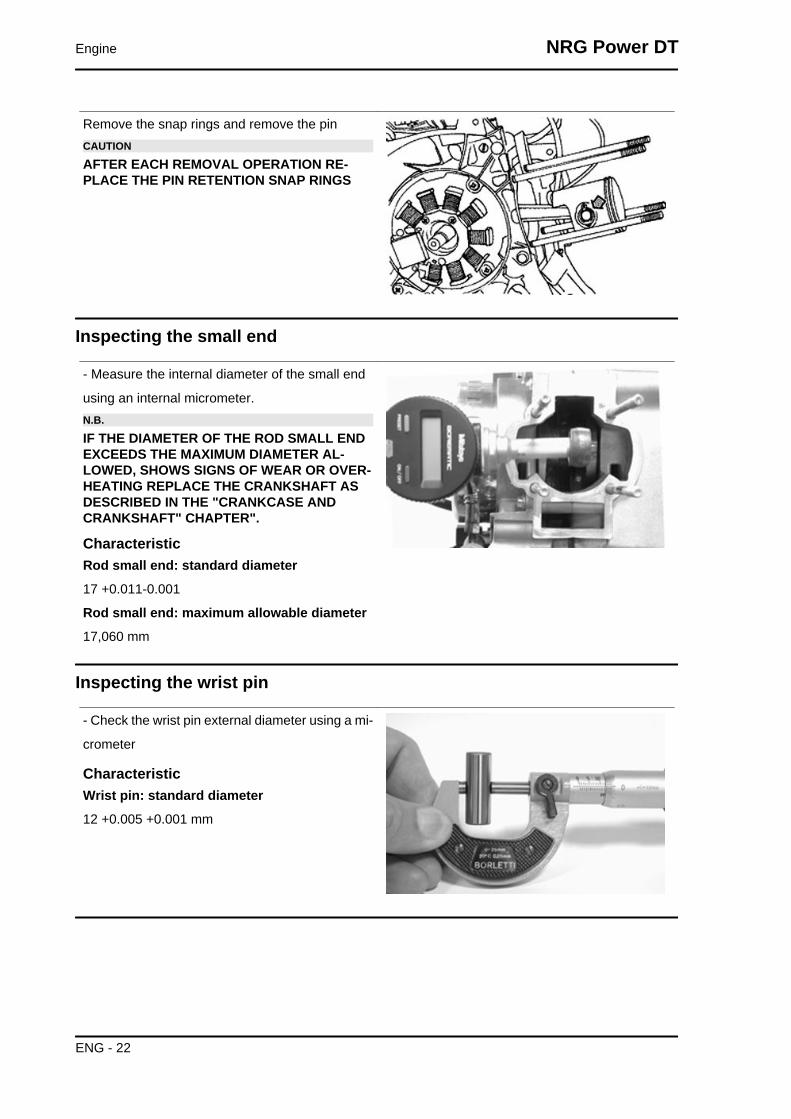
Remove the snap rings and remove the pinCAUTION
AFTER EACH REMOVAL OPERATION RE-PLACE THE PIN RETENTION SNAP RINGS
Inspecting the small end
- Measure the internal diameter of the small end
using an internal micrometer.N.B.
IF THE DIAMETER OF THE ROD SMALL ENDEXCEEDS THE MAXIMUM DIAMETER AL-LOWED, SHOWS SIGNS OF WEAR OR OVER-HEATING REPLACE THE CRANKSHAFT ASDESCRIBED IN THE "CRANKCASE ANDCRANKSHAFT" CHAPTER".
CharacteristicRod small end: standard diameter
17 +0.011-0.001
Rod small end: maximum allowable diameter
17,060 mm
Inspecting the wrist pin
- Check the wrist pin external diameter using a mi-
crometer
CharacteristicWrist pin: standard diameter
12 +0.005 +0.001 mm
Engine NRG Power DT
ENG - 22
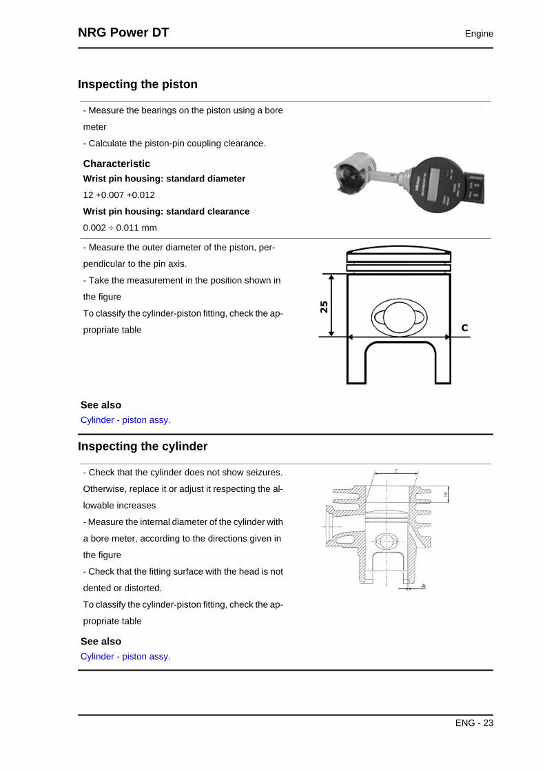
Inspecting the piston
- Measure the bearings on the piston using a bore
meter
- Calculate the piston-pin coupling clearance.
CharacteristicWrist pin housing: standard diameter
12 +0.007 +0.012
Wrist pin housing: standard clearance
0.002 ÷ 0.011 mm
- Measure the outer diameter of the piston, per-
pendicular to the pin axis.
- Take the measurement in the position shown in
the figure
To classify the cylinder-piston fitting, check the ap-
propriate table
See alsoCylinder - piston assy.
Inspecting the cylinder
- Check that the cylinder does not show seizures.
Otherwise, replace it or adjust it respecting the al-
lowable increases
- Measure the internal diameter of the cylinder with
a bore meter, according to the directions given in
the figure
- Check that the fitting surface with the head is not
dented or distorted.
To classify the cylinder-piston fitting, check the ap-
propriate table
See alsoCylinder - piston assy.
NRG Power DT Engine
ENG - 23
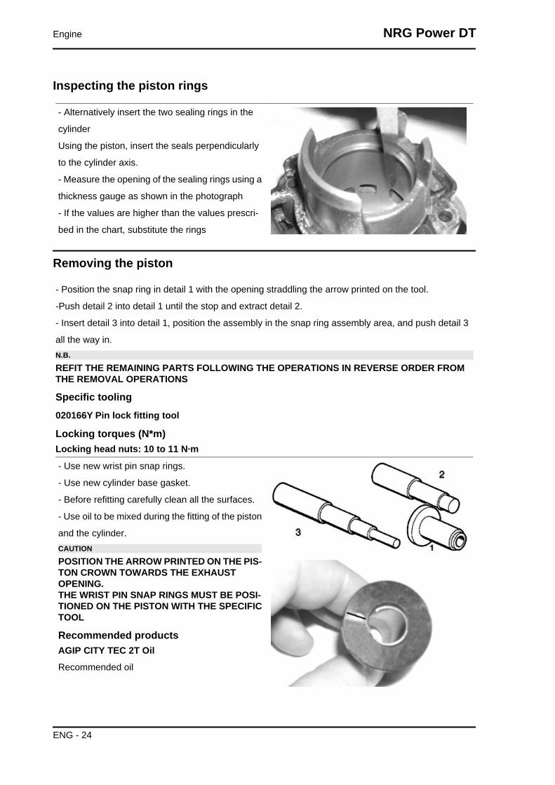
Inspecting the piston rings
- Alternatively insert the two sealing rings in the
cylinder
Using the piston, insert the seals perpendicularly
to the cylinder axis.
- Measure the opening of the sealing rings using a
thickness gauge as shown in the photograph
- If the values are higher than the values prescri-
bed in the chart, substitute the rings
Removing the piston
- Position the snap ring in detail 1 with the opening straddling the arrow printed on the tool.
-Push detail 2 into detail 1 until the stop and extract detail 2.
- Insert detail 3 into detail 1, position the assembly in the snap ring assembly area, and push detail 3
all the way in.N.B.
REFIT THE REMAINING PARTS FOLLOWING THE OPERATIONS IN REVERSE ORDER FROMTHE REMOVAL OPERATIONS
Specific tooling020166Y Pin lock fitting tool
Locking torques (N*m)Locking head nuts: 10 to 11 N·m
- Use new wrist pin snap rings.
- Use new cylinder base gasket.
- Before refitting carefully clean all the surfaces.
- Use oil to be mixed during the fitting of the piston
and the cylinder.CAUTION
POSITION THE ARROW PRINTED ON THE PIS-TON CROWN TOWARDS THE EXHAUSTOPENING.THE WRIST PIN SNAP RINGS MUST BE POSI-TIONED ON THE PISTON WITH THE SPECIFICTOOL
Recommended productsAGIP CITY TEC 2T Oil
Recommended oil
Engine NRG Power DT
ENG - 24

Inspecting the timing system componentsCAUTION
CHECK THE CORRECT REED UNIT SEAL; NOLIGHT MUST PASS BETWEEN THE SUPPORTAND LAMELLA.
Crankcase - crankshaft
NRG Power DT Engine
ENG - 25

Splitting the crankcase halves
Remove the eight crankcase union fasteners.
Install the special strip on the half crankcase on
the flywheel side and separate the half crankcase
on the flywheel side from the transmission side
Specific tooling020163Y Crankcase splitting plate
Removing the crankshaft
- Install the specific tool on the half crankcase on
the transmission side using four M6 screws of an
adequate length.
- Remove the crankshaft from the transmission
side half crankcase
Specific tooling020163Y Crankcase splitting plate
Engine NRG Power DT
ENG - 26

Removing the crankshaft bearings
The bearings can stay on either the half crankcase
or the crankshaft indifferently
- Using the special tool, remove any bearings that
have been left on the crankshaftN.B.
The half rings must be inserted on the bearingswith a few mallet blows.
Specific tooling004499Y001 Bearing extractor bell
004499Y006 Bearing extractor ring
004499Y002 Bearing extractor screw
004499Y007 Half rings
- Using the specific tool remove any bearings left
on the half crankcase
Specific tooling001467Y007 Driver for OD 54 mm bearing
001467Y006 Pliers to extract 20 mm bearings
Refitting the crankshaft bearings
Heat the bearings in an oil bath at around 150°C
and fit them on the crankshaft, if necessary using
a section of tube that acts on the bearing's inner
track
Specific tooling020265Y Bearing fitting base
NRG Power DT Engine
ENG - 27
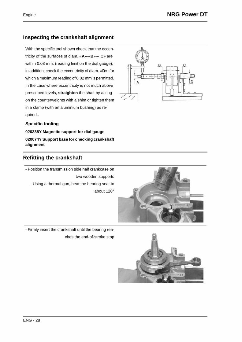
Inspecting the crankshaft alignment
With the specific tool shown check that the eccen-
tricity of the surfaces of diam. «A»-«B»-« C» are
within 0.03 mm. (reading limit on the dial gauge);
in addition, check the eccentricity of diam. «D», for
which a maximum reading of 0.02 mm is permitted.
In the case where eccentricity is not much above
prescribed levels, straighten the shaft by acting
on the counterweights with a shim or tighten them
in a clamp (with an aluminium bushing) as re-
quired..
Specific tooling020335Y Magnetic support for dial gauge
020074Y Support base for checking crankshaftalignment
Refitting the crankshaft
- Position the transmission side half crankcase on
two wooden supports
- Using a thermal gun, heat the bearing seat to
about 120°
- Firmly insert the crankshaft until the bearing rea-
ches the end-of-stroke stop
Engine NRG Power DT
ENG - 28

- Let the temperature of the half crankcase settle
at the temperature of the crankshaft.
- Again install the special crankcase separation
plate NOT installing the crankshaft protection
- During the assembly phase keep the central
thrust screw loose.
- Take the four clamping screws to the end of the
stroke and loosen them again with the same angle
(e.g. 90°)
- When the temperature has settled, preload the
thrust screw of the tool manually until the ball bear-
ing clearance is cancelled out.
Specific tooling020163Y Crankcase splitting plate
Refitting the crankcase halves
- Prepare the coupling surface with LOCTITE 510
applying a thin layer of it after degreasing the sur-
face using a suitable solvent (e.g. trichloroethy-
lene)
- Heat the flywheel-side half crankcase with a ther-
mal gun.
Recommended productsLoctite 510 Liquid sealant
Gasket
- Keeping the half crankcase on the transmission
side, insert the flywheel side half crankcase with a
clean precise movement
- Insert at least three clamping screws and tighten
up rapidly
- Insert the other 5 screws and tighten them to the
specified torque.
Locking torques (N*m)crankcase coupling screws 11 - 13
NRG Power DT Engine
ENG - 29

- Move the crankcase separation plate in a position
back from the one indicated in the figure
- Install the special magnetic support with dial
gauge at the end of the crankshaft
- Check the axial clearance of the crankcase
If this is not within the maximum limit allowed, re-
peat the crankcase coupling procedure
Specific tooling020335Y Magnetic support for dial gauge
CharacteristicAxial clearance with warm crankcase
0.10 ÷ 0.12 mm
Axial clearance with cold crankcase
0.06 to 0.08 mm
Limit value with cold crankcase
0.02 ÷ 0.03 mm
Lubrication
Crankshaft oil seals
Refitting
- Install a new flywheel-side oil seal only with the
special tool's punch
The flywheel-side oil seal is recognised by its
smaller diameterN.B.
THE USE OF THE SPECIFIC TOOL IS NOTCOMPATIBLE WITH THE FITTED WRENCH
Specific tooling020340Y Flywheel and transmission oil sealsfitting punch
Engine NRG Power DT
ENG - 30

- Install a new transmission side oil seal using the
special tool with adapter ring.
The transmission-side oil seal is recognised by the
larger diameter
Specific tooling020340Y Flywheel and transmission oil sealsfitting punch
Oil pump
Removal
- Remove the 2 screws shown in the figure
Remove the tube passage seal from the crank-
case shown in the figure
NRG Power DT Engine
ENG - 31

Refitting
To refit, perform the steps in the reverse direction
to disassembly
Remember to drain after refitting using the screw
shown in the figure
Fuel supply
The vehicle comes with a membrane pump con-
trolled by the depression that is generated in the
intake manifold. Therefore, the tank has an intake
in the lowest point that sends the fuel to the pump
and from here to the carburettor.
To determine the correct functioning of the pump,
the following measurements can be made on the
amounts distributed:
1) Start up the engine, bring it to normal operating
temperature and then shut it off.
2) Disconnect the fuel adduction line on the car-
burettor and insert it into a graduated tube.
3) Start up the engine without the accelerator and
keep it idle.
4) After the engine is started, count to 10 and then
turn it off.
5) Check that the quantity of fuel is not less than
the prescribed value.
CharacteristicFuel distributed
~100cc X 10"
Engine NRG Power DT
ENG - 32

INDEX OF TOPICS
SUSPENSIONS SUSP
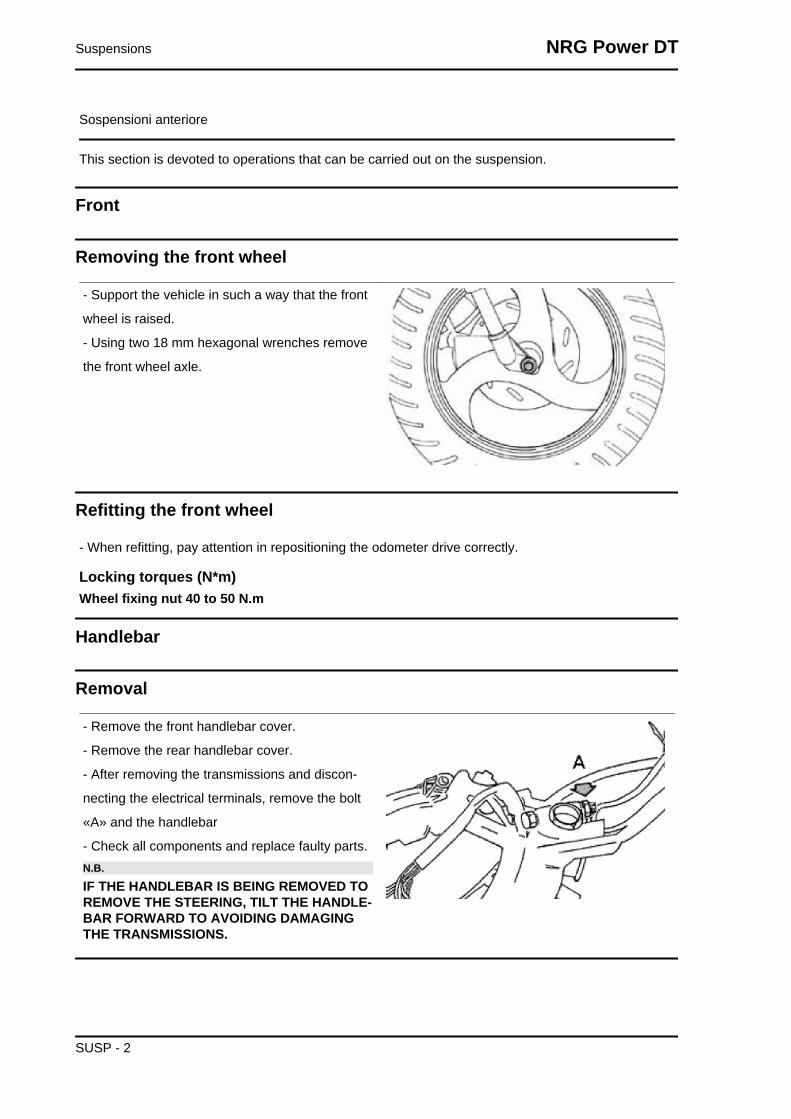
Sospensioni anteriore
This section is devoted to operations that can be carried out on the suspension.
Front
Removing the front wheel
- Support the vehicle in such a way that the front
wheel is raised.
- Using two 18 mm hexagonal wrenches remove
the front wheel axle.
Refitting the front wheel
- When refitting, pay attention in repositioning the odometer drive correctly.
Locking torques (N*m)Wheel fixing nut 40 to 50 N.m
Handlebar
Removal
- Remove the front handlebar cover.
- Remove the rear handlebar cover.
- After removing the transmissions and discon-
necting the electrical terminals, remove the bolt
«A» and the handlebar
- Check all components and replace faulty parts.N.B.
IF THE HANDLEBAR IS BEING REMOVED TOREMOVE THE STEERING, TILT THE HANDLE-BAR FORWARD TO AVOIDING DAMAGINGTHE TRANSMISSIONS.
Suspensions NRG Power DT
SUSP - 2

Refitting
When refitting, tighten to the prescribed torque and
apply the recommended grease to the threaded
cone.
Recommended productsAGIP GREASE PV2 Grease for control leverson the engine
White anhydrous-calcium based grease to protect
roller bearings; temperature range between -20 °
C and +120 °C; NLGI 2; ISO-L-XBCIB2
Locking torques (N*m)Locking torque: 65 to 70 N•m
Front fork
Removal
- Remove the front brake calliper.
- Remove the odometer cable from the reduction
gear box.
- Remove the front mudguard.
- Remove the handlebar.
After removing the steering ring-nut using the spe-
cial tool, lean the vehicle on one side and extract
the steering tube.
Specific tooling020055Y Wrench for steering tube ring nut
See alsoFront brake calliperHandlebar
OverhaulReplacing the seal ring
NRG Power DT Suspensions
SUSP - 3
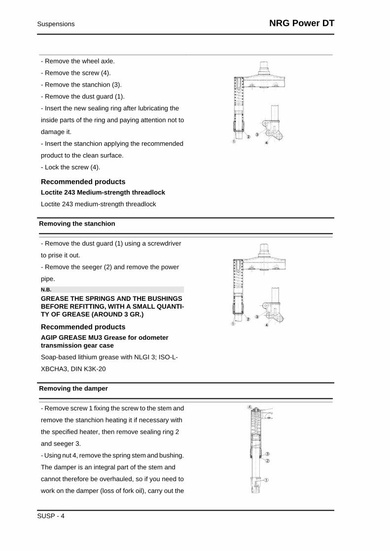
- Remove the wheel axle.
- Remove the screw (4).
- Remove the stanchion (3).
- Remove the dust guard (1).
- Insert the new sealing ring after lubricating the
inside parts of the ring and paying attention not to
damage it.
- Insert the stanchion appIying the recommended
product to the clean surface.
- Lock the screw (4).
Recommended productsLoctite 243 Medium-strength threadlock
Loctite 243 medium-strength threadlock
Removing the stanchion
- Remove the dust guard (1) using a screwdriver
to prise it out.
- Remove the seeger (2) and remove the power
pipe.N.B.
GREASE THE SPRINGS AND THE BUSHINGSBEFORE REFITTING, WITH A SMALL QUANTI-TY OF GREASE (AROUND 3 GR.)
Recommended productsAGIP GREASE MU3 Grease for odometertransmission gear case
Soap-based lithium grease with NLGI 3; ISO-L-
XBCHA3, DIN K3K-20
Removing the damper
- Remove screw 1 fixing the screw to the stem and
remove the stanchion heating it if necessary with
the specified heater, then remove sealing ring 2
and seeger 3.
- Using nut 4, remove the spring stem and bushing.
The damper is an integral part of the stem and
cannot therefore be overhauled, so if you need to
work on the damper (loss of fork oil), carry out the
Suspensions NRG Power DT
SUSP - 4

operations mentioned above and replace the
shock absorber-stem unit.
When refitting, tighten to the prescribed torque and
apply the recommended grease to the threadlock
nut.
Specific tooling020150Y Air heater support
020151Y Air heater
Recommended productsLoctite 243 Medium-strength threadlock
Loctite 243 medium-strength threadlock
Locking torques (N*m)Stud-stanchion fixing screw 20 to 25 N•m Nuttightening torque 20 to 25 N•m
Refitting
Lubricate the seats and the balls with the grease
recommended.
- Lock at the prescribed torque and turn the key
anticlockwise by 90° to 100°.
Specific tooling020055Y Wrench for steering tube ring nut
Recommended productsAGIP GREASE PV2 Grease for control leverson the engine
White anhydrous-calcium based grease to protect
roller bearings; temperature range between -20 °
C and +120 °C; NLGI 2; ISO-L-XBCIB2
Locking torques (N*m)Locking torque: 50 to 60 Nm
Steering column
RemovalRemoving the top and bottom frame housings
NRG Power DT Suspensions
SUSP - 5

- Only remove the seats if it is strictly necessary.
- Using the special tool remove the upper fifth
wheel seat by putting the special tool into the lower
part of the headstock as indicated in the figure.
- By inserting the punch into the top of the tube,
remove the lower fifth wheel seat from the head-
stock.
Specific tooling020004Y Punch for removing fifth wheels fromheadstock
RefittingRefitting the top and bottom frame housings
- Using the special tool, refit the upper and lower
bearing seats on the headstock.
Specific tooling001330Y Tool for fitting steering seats
Steering bearing
RemovalOverhauling the bearing housing on the fork
Check the condition of the fifth wheel and the fifth
wheel seat on the fork (steering tube). Replace if
there are faults.
- Support the fork properly.
- Using the special tool, remove the fifth wheel seat
on the steering tube as shown in the photograph
by applying small mallet blows.
Specific tooling020004Y Punch for removing fifth wheels fromheadstock
Suspensions NRG Power DT
SUSP - 6
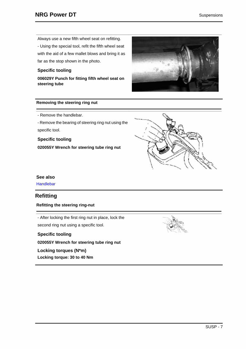
Always use a new fifth wheel seat on refitting.
- Using the special tool, refit the fifth wheel seat
with the aid of a few mallet blows and bring it as
far as the stop shown in the photo.
Specific tooling006029Y Punch for fitting fifth wheel seat onsteering tube
Removing the steering ring nut
- Remove the handlebar.
- Remove the bearing of steering ring nut using the
specific tool.
Specific tooling020055Y Wrench for steering tube ring nut
See alsoHandlebar
RefittingRefitting the steering ring-nut
- After locking the first ring nut in place, lock the
second ring nut using a specific tool.
Specific tooling020055Y Wrench for steering tube ring nut
Locking torques (N*m)Locking torque: 30 to 40 Nm
NRG Power DT Suspensions
SUSP - 7
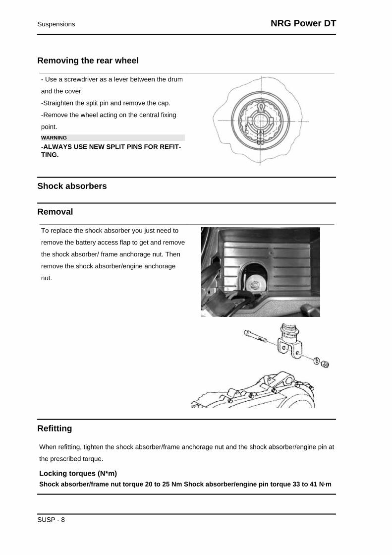
Removing the rear wheel
- Use a screwdriver as a lever between the drum
and the cover.
-Straighten the split pin and remove the cap.
-Remove the wheel acting on the central fixing
point.WARNING
-ALWAYS USE NEW SPLIT PINS FOR REFIT-TING.
Shock absorbers
Removal
To replace the shock absorber you just need to
remove the battery access flap to get and remove
the shock absorber/ frame anchorage nut. Then
remove the shock absorber/engine anchorage
nut.
Refitting
When refitting, tighten the shock absorber/frame anchorage nut and the shock absorber/engine pin at
the prescribed torque.
Locking torques (N*m)Shock absorber/frame nut torque 20 to 25 Nm Shock absorber/engine pin torque 33 to 41 N·m
Suspensions NRG Power DT
SUSP - 8

Centre-standRemoval of stand bolt from bracket
- Remove the stand support bracket from the en-
gine.
- Drill a 5 mm hole in the bracket so that the pin
«P» can come out.
Replacing the centre-stand assy
- Work on the screws shown in the figure.
- When refitting, secure to the prescribed torque.
Locking torques (N*m)Stand screw torque 18.5 to 19 Nm
Calking and fitting of stand bolt to bracket
- Caulk the end of the pin «P» between the two
punches shown in the figure.
- After caulking it must be possible for the stand to
turn freely.N.B.
UPON REFITTING USE NEW O-RING AND PIN,GREASE THE SPRING ATTACHMENTS ANDTHE PIN.
NRG Power DT Suspensions
SUSP - 9

Suspensions NRG Power DT
SUSP - 10

INDEX OF TOPICS
BRAKING SYSTEM BRAK SYS
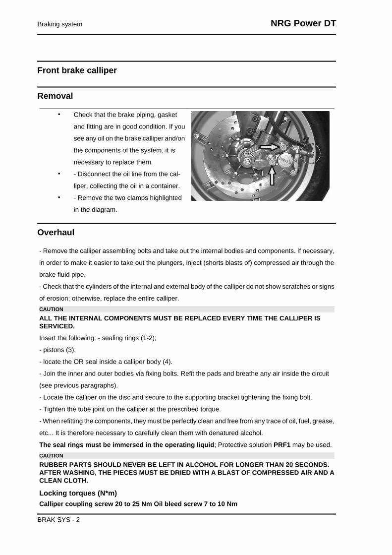
Front brake calliper
Removal
• Check that the brake piping, gasket
and fitting are in good condition. If you
see any oil on the brake calliper and/on
the components of the system, it is
necessary to replace them.
• - Disconnect the oil line from the cal-
liper, collecting the oil in a container.
• - Remove the two clamps highlighted
in the diagram.
Overhaul
- Remove the calliper assembling bolts and take out the internal bodies and components. If necessary,
in order to make it easier to take out the plungers, inject (shorts blasts of) compressed air through the
brake fluid pipe.
- Check that the cylinders of the internal and external body of the calliper do not show scratches or signs
of erosion; otherwise, replace the entire calliper.CAUTION
ALL THE INTERNAL COMPONENTS MUST BE REPLACED EVERY TIME THE CALLIPER ISSERVICED.Insert the following: - sealing rings (1-2);
- pistons (3);
- locate the OR seal inside a calliper body (4).
- Join the inner and outer bodies via fixing bolts. Refit the pads and breathe any air inside the circuit
(see previous paragraphs).
- Locate the calliper on the disc and secure to the supporting bracket tightening the fixing bolt.
- Tighten the tube joint on the calliper at the prescribed torque.
- When refitting the components, they must be perfectly clean and free from any trace of oil, fuel, grease,
etc... It is therefore necessary to carefully clean them with denatured alcohol.
The seal rings must be immersed in the operating liquid; Protective solution PRF1 may be used.CAUTION
RUBBER PARTS SHOULD NEVER BE LEFT IN ALCOHOL FOR LONGER THAN 20 SECONDS.AFTER WASHING, THE PIECES MUST BE DRIED WITH A BLAST OF COMPRESSED AIR AND ACLEAN CLOTH.
Locking torques (N*m)Calliper coupling screw 20 to 25 Nm Oil bleed screw 7 to 10 Nm
Braking system NRG Power DT
BRAK SYS - 2

1 DUST GUARDS
2 SEALING RINGS
3 PLUNGERS
4 O-RING GASKET
Refitting
• Refit the pincer on the support and
tighten the screws at the prescribed
torque.
• Refit the tube complete with fitting with
new copper gaskets.
• Bleed the air from the system.
Locking torques (N*m)Brake fluid tube calliper 20 ÷ 25 Nm Fasteningscrews calliper to the crankcase 20 - 25 Oilbleed screw 7 to 10 Nm
Front brake disc
Removal
- Remove the front wheel loosening the axle
clamp.
-Remove the six fastenings of the disc.
Refitting
-When refitting, position the disc correctly making sure that it rotates in the right direction.
Locking torques (N*m)Disc tightening screw 8 - 12
NRG Power DT Braking system
BRAK SYS - 3

Disc Inspection
Checking the disc is important; it must be perfectly
clean, with no sign of rust, oil or grease or other
dirt and must not show signs of deep scoring.
CharacteristicNew rear disc thickness
4.0 mm
Disc thickness at wear limit (front)
3.5 mm
• Using the appropriate tool, measure
how much the disc protrudes when the
wheel is fitted properly. The protrusion,
measured near the external edge of
the disc, must be less than 0.1 mm.
• If a value is measured other than the
specified value, remove the front wheel
(Front/Rear Suspension chapter) and
check the protrusion of the disc. Maxi-
mum permissible out of true is 0.1 mm.
If the value measured is greater, re-
place the disc and repeat the check.
• If the problem persists, check and re-
place the wheel hub if necessary.
Specific tooling020335Y Magnetic support for dial gauge
Front brake pads
Braking system NRG Power DT
BRAK SYS - 4
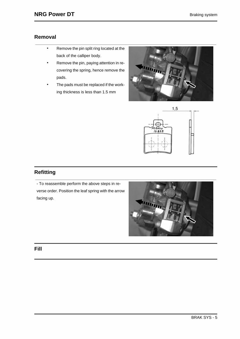
Removal
• Remove the pin split ring located at the
back of the calliper body.
• Remove the pin, paying attention in re-
covering the spring, hence remove the
pads.
• The pads must be replaced if the work-
ing thickness is less than 1.5 mm
Refitting
- To reassemble perform the above steps in re-
verse order. Position the leaf spring with the arrow
facing up.
Fill
NRG Power DT Braking system
BRAK SYS - 5

Front
-Once the bleed valve is closed, fill the system with
brake liquid to the maximum level.
-Undo the bleed screw.
-Apply the tube of the special tool to the bleed
screws.
When bleeding it is necessary to fill the oil tank in
continuation while working with a MITYVAC pump
on the bleed screws until no more air comes out of
the system.
The operation is finished when just oil comes out
of the bleed screws.
-Do up the bleed screw.
-When the operation is over, tighten up the oil
bleed screw to the prescribed torque.N.B.
IF AIR CONTINUES TO COME OUT DURINGPURGING, EXAMINE ALL THE FITTINGS:IF SAID FITTINGS DO NOT SHOW SIGNS OFBEING FAULTY, LOOK FOR THE AIR INPUTAMONG THE VARIOUS SEALS ON THE PUMPAND CALLIPER PISTONS.CAUTION
- DURING THE OPERATIONS, THE VEHICLEMUST BE ON THE STAND AND LEVEL.N.B.
DURING PURGING FREQUENTLY CHECK THELEVEL TO PREVENT AIR GETTING INTO THESYSTEM THROUGH THE PUMP.WARNING
- BRAKING CIRCUIT FLUID IS HYGROSCOPIC.IT ABSORBS HUMIDITY FROM THE SUR-ROUNDING AIR.IF THE LEVEL OF HUMIDITY IN THE BRAKINGFLUID EXCEEDS A GIVEN VALUE, BRAKINGEFFICIENCY WILL BE REDUCED.THEREFORE, ALWAYS USE FLUID FROMSEALED CONTAINERS.UNDER NORMAL DRIVING AND CLIMATICCONDITIONS YOU SHOULD CHANGE THISLIQUID EVERY TWO YEARS.IF THE BRAKES ARE USED INTENSELY AND/OR IN HARSH CONDITIONS, CHANGE THEFLUID MORE FREQUENTLY.CAUTION
WHEN CARRYING OUT THE OPERATION,BRAKE FLUID MAY LEAK FROM BETWEEN
Braking system NRG Power DT
BRAK SYS - 6

THE BLEED SCREW AND ITS SEAT ON THECALLIPER.CAREFULLY DRY THE CALLIPER AND DE-GREASE THE DISC SHOULD THERE BE OILON IT.
Specific tooling020329Y MityVac vacuum-operated pump
Recommended productsAGIP BRAKE 4 Brake fluid
FMVSS DOT 4 Synthetic fluid
Locking torques (N*m)Oil bleed screw 8÷12
Front brake pump
-After removing the front and rear handlebar covers, act on the two stand fixing points (see the figure).
- Disconnect the tube, collecting the brake oil in a container.
- On refitting, perform the operation in reverse.
- Tighten the hydraulic line to the prescribed torque
and bleed the system.
Locking torques (N*m)Brake fluid pump - hose fitting 20 ÷ 25 Nm
Removal
- Bleed the circuit and drain the brake fluid through
the bleeding screw located on the calliper and ac-
tuate the brake lever until no more fluid flows out.
-Remove the oil pump from the handlebar; remove
the brake lever and then remove the wheel cylin-
der.
1 - Tank cap screw.
2. Tank cover.
3. Diaphragm.
4. Bellows.
5. Sealing ring.
6. Piston.
NRG Power DT Braking system
BRAK SYS - 7

7. Gasket.
8 - SpringCAUTION
- THE PRESENCE OF BRAKE FLUID ON THEDISC OR BRAKE PADS REDUCES THE BRAK-ING EFFICIENCY.IN THIS CASE, REPLACE THE PADS ANDCLEAN THE DISC WITH A HIGH-QUALITY SOL-VENT.CONTACT WITH BRAKE FLUID WILL DAMAGEPAINTED SURFACES.RUBBER PARTS SHOULD NEVER BE LEFT INALCOHOL FOR LONGER THAN 20 SECONDS.AFTER WASHING, THE PIECES MUST BEDRIED WITH A BLAST OF COMPRESSED AIRAND A CLEAN CLOTH.THE SEALING RINGS MUST BE IMMERSED INTHE OPERATING LIQUID.
Refitting
Before fitting, the parts must be perfectly clean and
free of traces of oil, diesel fuel, grease, etc.. They
should be washed thoroughly in denatured alcohol
before proceeding.
- Reinstall the individual parts in the reverse order
to the removal, paying attention to the correct po-
sitioning of the rubber parts in order to ensure leak
tightness.
1 - Tank cap screw.
2. Tank cover.
3. Diaphragm.
4. Bellows.
5. Sealing ring.
6. Piston.
7. Gasket.
8. Spring.
Braking system NRG Power DT
BRAK SYS - 8
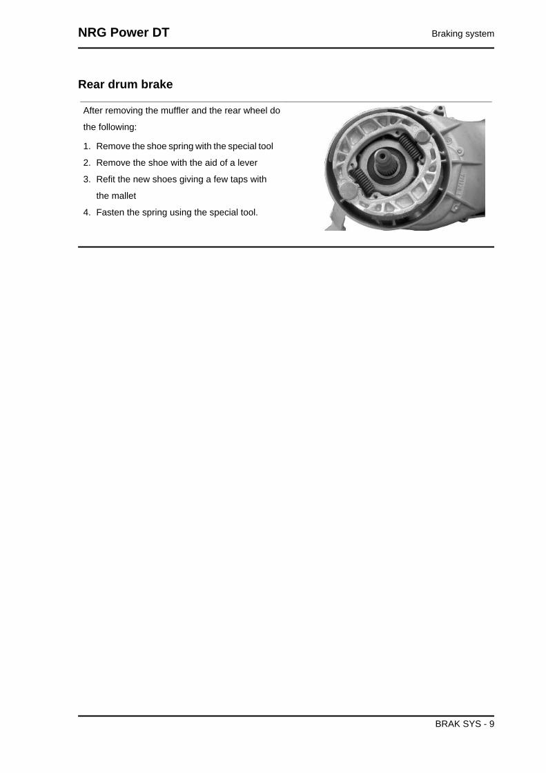
Rear drum brake
After removing the muffler and the rear wheel do
the following:
1. Remove the shoe spring with the special tool
2. Remove the shoe with the aid of a lever
3. Refit the new shoes giving a few taps with
the mallet
4. Fasten the spring using the special tool.
NRG Power DT Braking system
BRAK SYS - 9

Braking system NRG Power DT
BRAK SYS - 10

INDEX OF TOPICS
CHASSIS CHAS
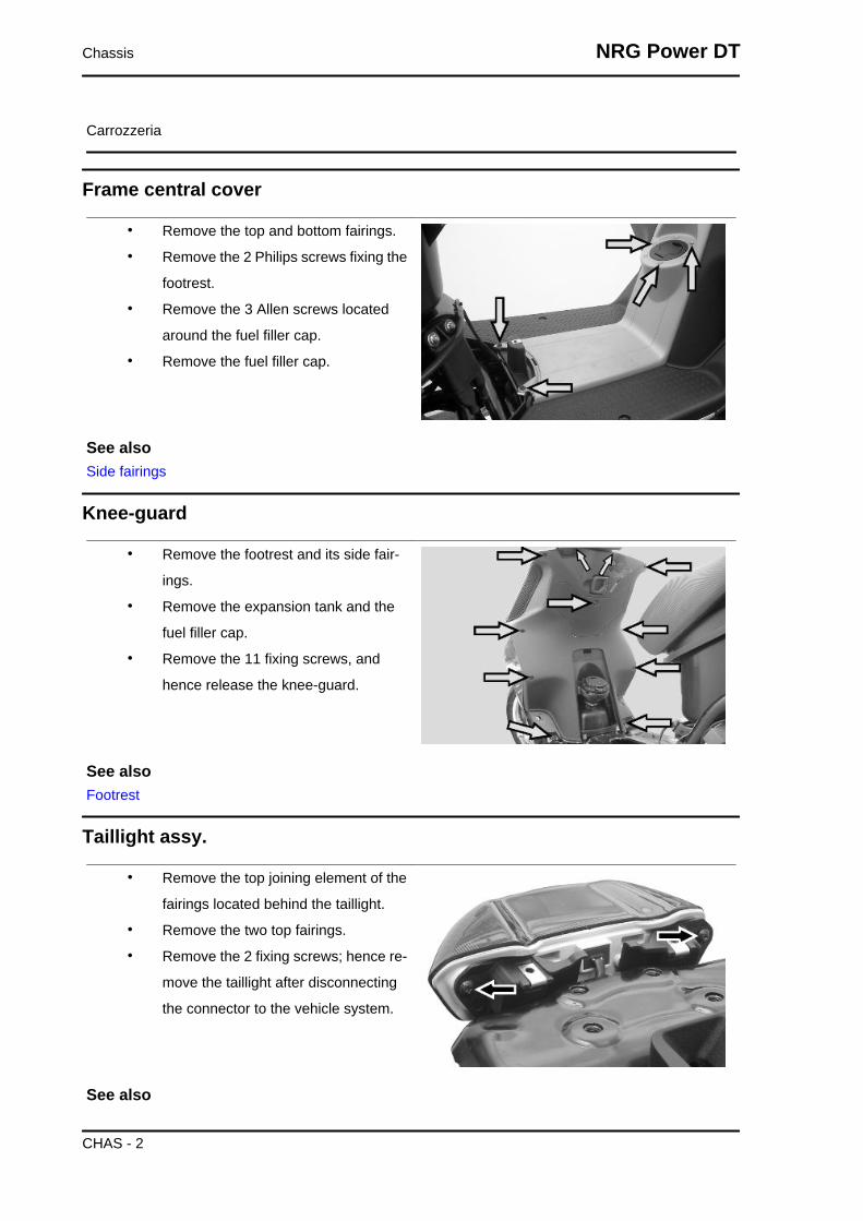
Carrozzeria
Frame central cover
• Remove the top and bottom fairings.
• Remove the 2 Philips screws fixing the
footrest.
• Remove the 3 Allen screws located
around the fuel filler cap.
• Remove the fuel filler cap.
See alsoSide fairings
Knee-guard
• Remove the footrest and its side fair-
ings.
• Remove the expansion tank and the
fuel filler cap.
• Remove the 11 fixing screws, and
hence release the knee-guard.
See alsoFootrest
Taillight assy.
• Remove the top joining element of the
fairings located behind the taillight.
• Remove the two top fairings.
• Remove the 2 fixing screws; hence re-
move the taillight after disconnecting
the connector to the vehicle system.
See also
Chassis NRG Power DT
CHAS - 2

Side fairings
Footrest
• Remove the centre frame cover.
• Remove the 10 screws (5 for each
side), hence remove the footrest.
• Remove the side fairing from the foot-
rest, by removing the two screws join-
ing this to the spoiler and the knee-
guard.
See alsoFrame central cover
Side fairings
• Remove the top l.h.s. and r.h.s. fair-
ings, by removing the 3 side screws
and the screw located underneath the
taillight
NRG Power DT Chassis
CHAS - 3

• Remove the lower fairings, removing
the 2 side screws and the central join-
ing screw located underneath the
spark plug cover.
License plate holder
• Remove the top fairing joining element
located behind the taillight.
• Remove the 2 screws joining the top
side fairings.
• Remove the 4 lower screws joining the
front wheel housing cover with the low-
er side fairings.
See alsoSide fairings
Fuel tank
• Remove the footrest and its side fair-
ings.
• Remove the 2 Allen screws fixing the
fuel support cross member, and re-
move the bracket
Chassis NRG Power DT
CHAS - 4

• Remove the metallic clip joining the
rubber bellow to the tank and loosen
the 3 screws fixing to the knee-guard
• Remove the 2 top screws fixing the
tank to the frame and lower the tank so
to disconnect the inlet and outlet fuel
hoses from the pump.
• Remove the tank completely paying at-
tention to avoid fuel spillage.
See alsoFootrest
NRG Power DT Chassis
CHAS - 5

Chassis NRG Power DT
CHAS - 6
INDEX OF TOPICS
PRE-DELIVERY PRE DE

Aesthetic inspection
Appearance check:
- Paintwork
- Fitting of plastics
- Scratches
- Dirt
Tightening torques inspection
Lock check
- Safety locks
- clamping screws
Safety locks
Rear shock absorber upper fixing
Rear shock absorber lower fixing
Front wheel axle nut
Wheel hub nut
Frame - swinging arm bolt *
Swinging arm bolt - Engine
Engine arm pin - Frame arm
Handlebar lock nut
Steering lower ring nut
Upper steering ring nut
Electrical system
Electrical system
- Main switch
- Headlamps: high beam, low beam, position and parking lights and the respective warning lights
- Adjusting the headlights according to the regulations currently in force
- Tail light, parking light, stop light
- Front and rear stop light switches
- Turn indicators and their warning lights
- Instrument lighting
- Instrument panel: fuel and temperature indicator
- Instrument panel warning lights
- Horn
- Starter
Pre-delivery NRG Power DT
PRE DE - 2

CAUTION
TO ENSURE MAXIMUM PERFORMANCE, THE BATTERY MUST BE CHARGED BEFORE USE.INADEQUATE CHARGING OF THE BATTERY WITH A LOW LEVEL OF ELECTROLYTE BEFOREIT IS FIRST USED SHORTENS THE LIFE OF THE BATTERY.WARNING
BEFORE RECHARGING THE BATTERY, REMOVE THE CAPS OF EACH CELL.KEEP THE BATTERY AWAY FROM NAKED FLAMES OR SPARKS WHILE IT IS CHARGED.REMOVE THE BATTERY FROM THE SCOOTER, DISCONNECTING THE NEGATIVE TERMINALFIRST.CAUTION
WHEN INSTALLING THE BATTERY, ATTACH THE POSITIVE LEAD FIRST AND THEN THE NEG-ATIVE LEAD.WARNING
BATTERY ELECTROLYTE IS TOXIC AND IT MAY CAUSE SERIOUS BURNS. IT CONTAINS SUL-PHURIC ACID. AVOID CONTACT WITH EYES, SKIN AND CLOTHING.IN CASE OF CONTACT WITH EYES OR SKIN, RINSE WITH ABUNDANT WATER FOR ABOUT 15MINUTES AND SEEK MEDICAL ATTENTION AT ONCE.IF IT IS SWALLOWED, IMMEDIATELY DRINK LARGE QUANTITIES OF WATER OR VEGETABLEOIL. SEEK IMMEDIATE MEDICAL ATTENTION.THE BATTERIES PRODUCE EXPLOSIVE GAS; KEEP THEM AWAY FROM NAKED FLAMES,SPARKS AND CIGARETTES. IF THE BATTERY IS CHARGED IN A CLOSED PLACE, TAKE CARETO ENSURE ADEQUATE VENTILATION. ALWAYS PROTECT YOUR EYES WHEN WORKINGCLOSE TO BATTERIES.KEEP OUT OF THE REACH OF CHILDRENCAUTION
NEVER USE FUSES WITH A CAPACITY HIGHER THAN THE RECOMMENDED CAPACITY. USINGA FUSE OF UNSUITABLE RATING MAY SERIOUSLY DAMAGE THE VEHICLE OR EVEN CAUSEA FIRE.
Levels check
Level check:
- Hydraulic braking system fluid level.
- Rear hub oil level
- Engine coolant level.
Road test
Test ride
- Cold start
- Instrument operations
- Response to the throttle control
- Stability on acceleration and braking
- Rear and front brake efficiency
- Rear and front suspension efficiency
- Abnormal noise
NRG Power DT Pre-delivery
PRE DE - 3

Static test
Static control after the test ride:
- Starting when warm
- Starter operation
- Minimum hold (turning the handlebar)
- Uniform turning of the steering
- Possible leaksCAUTION
CHECK AND ADJUST TYRE PRESSURE WITH TYRES AT AMBIENT TEMPERATURE.CAUTION
NEVER EXCEED THE RECOMMENDED INFLATION PRESSURES OR TYRES MAY BURST.
Functional inspection
Functional check up:
Braking system (hydraulic)
- Lever travel
Braking system (mechanical)
- Lever travel
Clutch
- Proper functioning check
Engine
- Throttle travel check
Others
- Check documentation
- Check the frame and engine numbers
- Tool kit
- License plate fitting
- Check locks
- Check tyre pressures
- Installation of mirrors and any accessories
Pre-delivery NRG Power DT
PRE DE - 4

INDEX OF TOPICS
TIME TIME

This section is devoted to the time necessary to
carry out repairs.
The description and code for each operation is in-
dicated.
Engine
ENGINE
Code Action Duration1 001001 Engine to chassis - Replace-
ment
Time NRG Power DT
TIME - 2

Crankcase
CRANKCASECode Action Duration
1 001133 Engine crankcase - Replace-ment
NRG Power DT Time
TIME - 3

Crankshaft
CRANKSHAFT
Code Action Duration1 001117 Crankshaft - Replacement2 001118 Main bearings - Replacement3 001099 Oil seal, flywheel side - Re-
placement4 001100 Oil seal, clutch side - Re-
placement
Time NRG Power DT
TIME - 4

Cylinder assy.
CYLINDER / PISTON
Code Action Duration1 001002 Cylinder piston - Replace-
ment2 001107 Cylinder / piston - Inspection /
cleaning
NRG Power DT Time
TIME - 5

Cylinder head assy.
CYLINDER HEAD ASSEMBLY
Code Action Duration1 001013 Intake manifold - Replace-
ment2 001093 Spark plug - Replacement3 001126 Head - Replacement4 001097 Cooling hood - Replacement5 001178 Disc pack - Replacement6 001087 Flywheel cover - Replace-
ment
Time NRG Power DT
TIME - 6

Driven pulley
DRIVEN PULLEY
Code Action Duration1 001110 Driven pulley - Replacement2 001022 Clutch - Replacement3 001155 Clutch bell housing - Re-
placement4 001012 Driven pulley - overhaul
NRG Power DT Time
TIME - 7
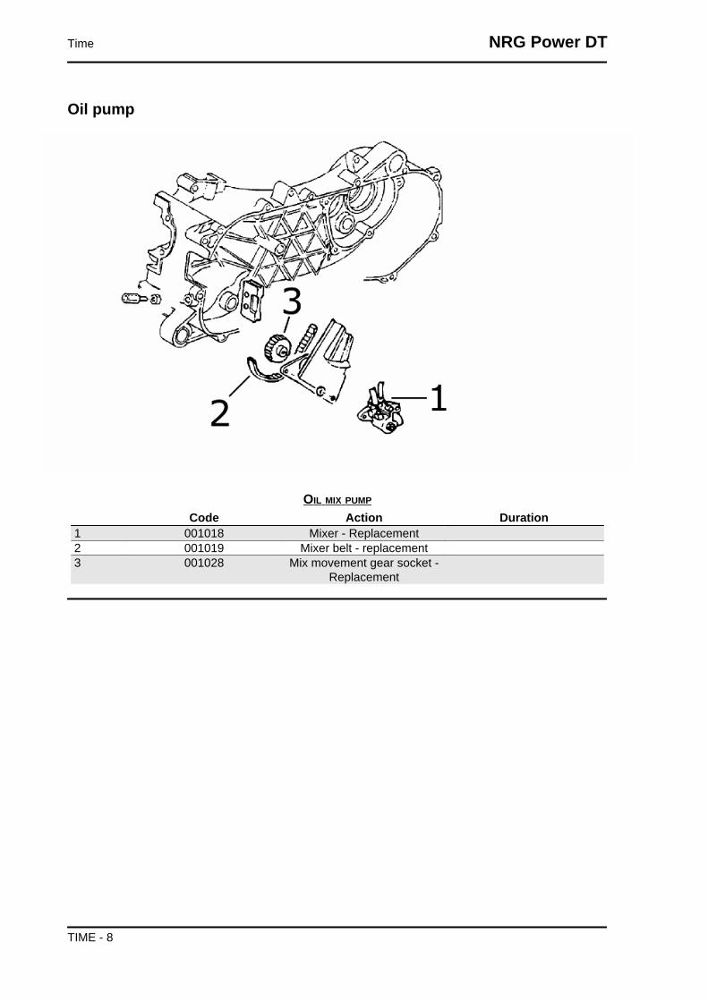
Oil pump
OIL MIX PUMP
Code Action Duration1 001018 Mixer - Replacement2 001019 Mixer belt - replacement3 001028 Mix movement gear socket -
Replacement
Time NRG Power DT
TIME - 8

Final gear assy.
FINAL REDUCTION GEAR
Code Action Duration1 001010 Geared reduction unit - Serv-
ice2 001156 Gear reduction unit cover -
Replacement3 003065 Gearcase oil - Replacement4 004125 Rear wheel axle - Replace-
ment
NRG Power DT Time
TIME - 9

Driving pulley
DRIVING PULLEY
Code Action Duration1 001011 Driving belt - Replacement2 001066 driving pulley - Replacement3 001017 Starter sprocket wheel - Re-
placement4 001086 Driving half-pulley - replace5 001177 Variator rollers / shoes - Re-
placement
Time NRG Power DT
TIME - 10

Transmission cover
TRANSMISSION COVER
Code Action Duration1 001096 Transmission crankcase cov-
er - Replacement2 001131 Transmission air intake - Re-
placement3 001132 Transmission air inlet pipe -
Replacement4 001135 Transmission cover bearing -
Replacement5 004179 Stand buffer - Replacement
NRG Power DT Time
TIME - 11
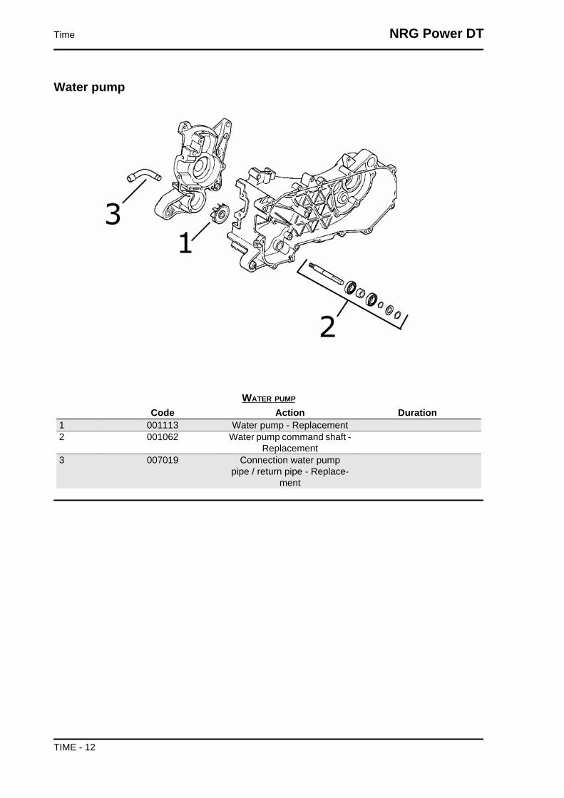
Water pump
WATER PUMP
Code Action Duration1 001113 Water pump - Replacement2 001062 Water pump command shaft -
Replacement3 007019 Connection water pump
pipe / return pipe - Replace-ment
Time NRG Power DT
TIME - 12

Starter motor
STARTER MOTOR AND KICK STARTER
Code Action Duration1 001020 Starter motor - Replacement2 001021 Kick starter - Inspection3 001084 Starter lever - Replacement4 008008 Starter spring pack - Re-
placement5 005045 Starter motor cable harness -
Replacement
NRG Power DT Time
TIME - 13

Flywheel magneto
MAGNETO FLYWHEEL
Code Action Duration1 001058 Flywheel - Replacement2 001067 Stator - Replacement3 001173 Rotor - Replacement4 001109 Cooling fan - Replacement
Time NRG Power DT
TIME - 14
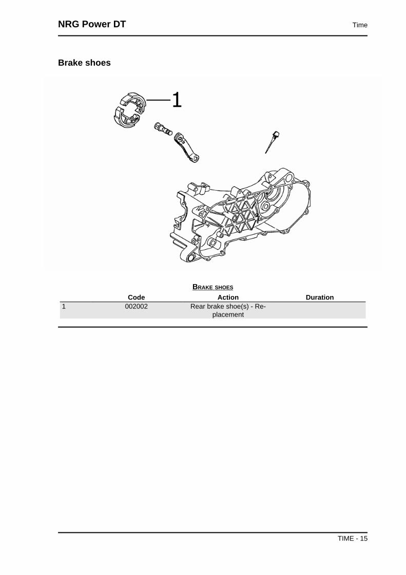
Brake shoes
BRAKE SHOES
Code Action Duration1 002002 Rear brake shoe(s) - Re-
placement
NRG Power DT Time
TIME - 15

Carburettor
CARBURETTOR INSPECTION
Code Action Duration1 001081 Automatic choke - Replace-
ment2 001008 Carburettor - Inspection
Time NRG Power DT
TIME - 16

Exhaust pipe
MUFFLER
Code Action Duration1 001009 Muffler - Replacement2 001095 Muffler guard - Replacement3 001136 Exhaust emissions - Adjust-
ment
NRG Power DT Time
TIME - 17

Air cleaner
AIR FILTER
Code Action Duration1 001014 Air filter - Replacement /
cleaning2 001015 Air filter box - Replacement3 004122 Air cleaner carburettor fitting -
Replacement
Time NRG Power DT
TIME - 18

Frame
CHASSIS
Code Action Duration1 001053 Stand bolt - Replacement2 004004 Stand - Replacement3 004001 Frame - replace4 004015 Footrest - Replacement5 004171 Stand support plate - Re-
placement6 004143 Footrest support - replace
NRG Power DT Time
TIME - 19
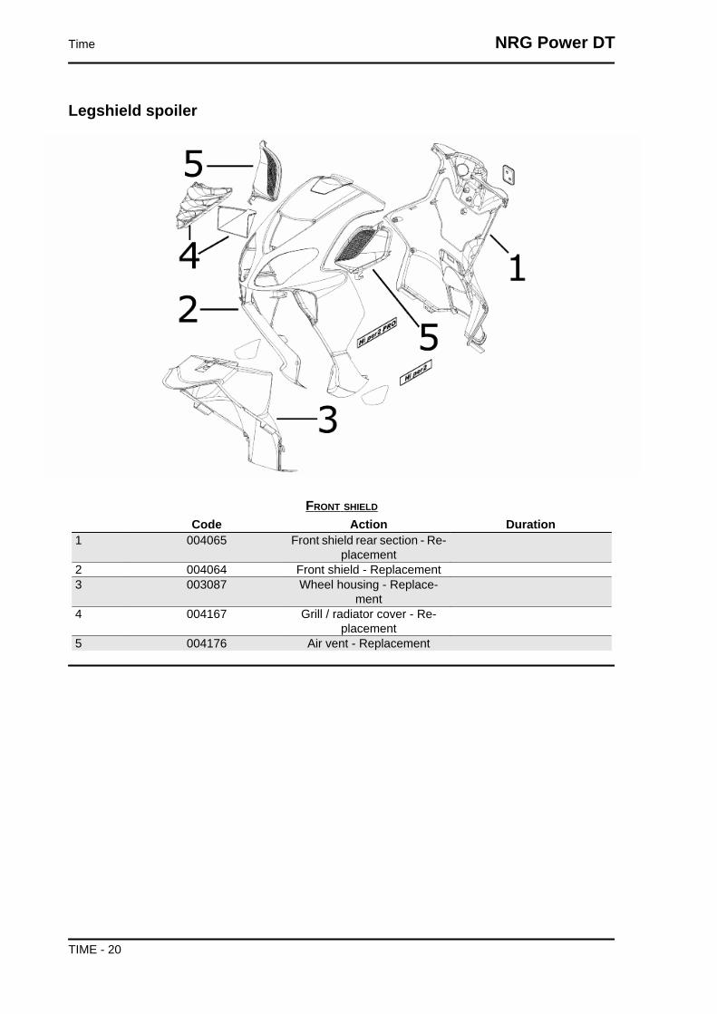
Legshield spoiler
FRONT SHIELD
Code Action Duration1 004065 Front shield rear section - Re-
placement2 004064 Front shield - Replacement3 003087 Wheel housing - Replace-
ment4 004167 Grill / radiator cover - Re-
placement5 004176 Air vent - Replacement
Time NRG Power DT
TIME - 20

Side fairings
CENTRAL COVER
Code Action Duration1 004053 Spoiler - Replacement2 004178 Footrest - Replacement3 004011 Central chassis cover - Re-
placement
NRG Power DT Time
TIME - 21

Underseat compartment
HELMET COMPARTMENT
Code Action Duration1 004059 Spark plug inspection flap -
Replacement2 004016 Helmet compartment - Re-
placement3 005046 Battery cover - Replacement
Time NRG Power DT
TIME - 22

Plate holder
LICENSE PLATE HOLDER
Code Action Duration1 005022 Rear turn indicators - Re-
placement2 005068 Rear turn indicator bulb - Re-
placement3 005005 Taillight - Replacement4 005023 Rear tail light support - Re-
placement5 005091 Turn indicator glass - Re-
placement
NRG Power DT Time
TIME - 23

Mudguard
MUDGUARDS
Code Action Duration1 004009 Rear mudguard - Replace-
ment2 004052 Bumper - Replacement3 004002 Front mudguard - Replace-
ment
Time NRG Power DT
TIME - 24
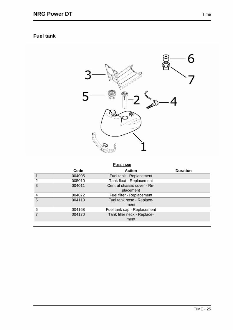
Fuel tank
FUEL TANK
Code Action Duration1 004005 Fuel tank - Replacement2 005010 Tank float - Replacement3 004011 Central chassis cover - Re-
placement4 004072 Fuel filter - Replacement5 004110 Fuel tank hose - Replace-
ment6 004168 Fuel tank cap - Replacement7 004170 Tank filler neck - Replace-
ment
NRG Power DT Time
TIME - 25

Tank oil
OIL TANK
Code Action Duration1 004017 Oil reservoir - Replacement2 005018 Oil reservoir float - Replace-
ment3 004095 Oil reservoir cock - Replace-
ment4 004091 Oil reservoir hose - Replace-
ment
Time NRG Power DT
TIME - 26
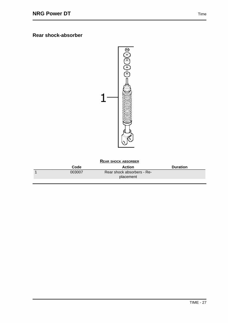
Rear shock-absorber
REAR SHOCK ABSORBER
Code Action Duration1 003007 Rear shock absorbers - Re-
placement
NRG Power DT Time
TIME - 27

Steering column bearings
STEERING FIFTH WHEELS
Code Action Duration1 003002 Steering fifth wheel - Re-
placement2 003073 Steering clearance - Adjust-
ment3 004119 Bearing / upper steering fifth
wheel - Replacement
Time NRG Power DT
TIME - 28

Handlebar components
LHS HANDLEBAR COMPONENTSCode Action Duration
1 004066 Rear-view mirror - Replace-ment
2 002071 Left hand grip - Replacement3 003059 Counterweight - Replace-
ment4 002037 Brake or clutch lever - Re-
placement
NRG Power DT Time
TIME - 29

HANDLEBAR COMPONENTSCode Action Duration
1 003001 Handlebar - Replacement2 002060 Complete throttle control -
Replacement3 002059 Right hand grip - Replace-
ment4 005017 Stop switch - Replacement5 003059 Counterweight - Replace-
ment6 002024 Front brake pump - replace7 002037 Brake or clutch lever - Re-
placement8 002047 Front brake fluid and air
bleeding system - Replace-ment
9 003061 Accelerator transmission -Adjustment
Time NRG Power DT
TIME - 30

Swing-arm
SWINGING ARM
Code Action Duration1 001072 Engine / frame swinging arm
fitting - Replacement
NRG Power DT Time
TIME - 31

Seat
SEAT
Code Action Duration1 004003 Saddle - Replacement2 004054 Seat lock hook - Replace-
ment3 002083 Saddle opening transmission
- Replacement
Time NRG Power DT
TIME - 32

Instrument panel
INSTRUMENT UNIT AND HANDLEBAR COVER
Code Action Duration1 005014 Odometer - Replacement2 004018 Handlebar front section - Re-
placement3 004019 Handlebar rear section - Re-
placement4 005078 Odometer glass - Replace-
ment
NRG Power DT Time
TIME - 33

Turn signal lights
FRONT LIGHT
Code Action Duration1 005067 Front turn indicator bulb - Re-
placement2 005008 Front headlamp bulbs - Re-
placement3 005002 Front headlamp - change4 005012 Front turn indicator - Re-
placement
Time NRG Power DT
TIME - 34

Front wheel
FRONT WHEEL
Code Action Duration1 002041 Front brake disc - Replace-
ment2 003040 Front wheel bearings - Re-
placement3 003037 Front wheel rim- Replace-
ment4 003047 Front tyre - Replacement5 004123 Front wheel - Replacement6 003038 Front wheel axle - Replace-
ment7 005089 Tone wheel - Replacement
Grease tone wheel or drive
Please take note that the code has been intro-
duced:
900001 - Tone wheel / drive greasing - 15'.
Never mistake the codes 002011 (movement sen-
sor replacement) and 005089 (tone wheel replace-
ment) in the event of noise of the indicated
components. The grease recommended is TUTE-
LA MRM 2 (soap-based lithium grease with Mo-
lybdenum disulphide).
NRG Power DT Time
TIME - 35

In the following points we indicate with an arrow
the area to be greased (1 - Drive, 2 - Tone wheel)
Rear wheel
REAR WHEEL
Code Action Duration1 001071 Rear wheel rim - Replace-
ment2 001016 Rear wheel - Replacement3 004126 Rear wheel tyre - Replace-
ment
Time NRG Power DT
TIME - 36

Fuel pump
FUEL PUMP
Code Action Duration1 004073 Fuel pump - Replacement2 004137 Pump / carburettor hose - Re-
placement3 004086 Petrol pump depression tube
- Replacement
NRG Power DT Time
TIME - 37
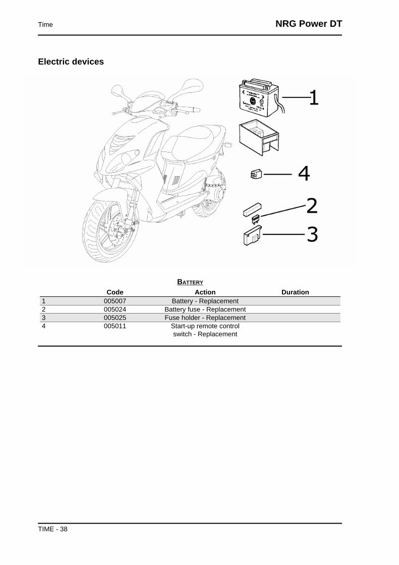
Electric devices
BATTERY
Code Action Duration1 005007 Battery - Replacement2 005024 Battery fuse - Replacement3 005025 Fuse holder - Replacement4 005011 Start-up remote control
switch - Replacement
Time NRG Power DT
TIME - 38

ELECTRICS
Code Action Duration1 001023 Control unit - Replacement2 001094 Spark plug cap - Replace-
ment3 005001 Electrical system - Replace-
ment4 005009 Voltage regulator - replace5 005136 Resistance - Replacement6 005044 Front lights cable unit- Re-
placement
NRG Power DT Time
TIME - 39

Electronic controls
ELECTRICAL COMMANDS
Code Action Duration1 005041 Starter button - Replacement2 005040 Horn button - Replacement3 005016 Key switch - Replacement4 004096 Lock series - Replacement5 004010 Antitheft lock - replace6 005003 Horn - Replacement7 005006 Light or turn indicator switch -
Replacement8 005039 Headlight switch - Replace-
ment
Time NRG Power DT
TIME - 40

Transmissions
REAR BRAKE TRANSMISSIONS AND ODOMETERCode Action Duration
1 002053 Rear brake transmissioncomplete - Replacement
NRG Power DT Time
TIME - 41

SPLITTER
Code Action Duration1 002012 Splitter - Replacement2 002058 Mix / splitter transmission
complete - Replacement3 002057 Carburettor / splitter trans-
mission complete - Replace-ment
4 002054 Throttle or splitter transmis-sion complete - Replacement
Brake callipers
FRONT CALLIPERCode Action Duration
1 002007 Front brake pads - Replace-ment
2 002021 Front brake piping - Replace-ment
3 002039 Front brake calliper - Re-placement
Time NRG Power DT
TIME - 42

Rear side fairings
REAR COVERS
Code Action Duration1 004159 Plates / Stickers - Replace-
ment2 004056 Upper rear light cover - Re-
placement3 004036 Lower chassis cover - Re-
placement4 004085 Fairing (1) - Replacement5 004129 Rear fairing - Replacement
NRG Power DT Time
TIME - 43

Front suspension
FORK
Code Action Duration1 003010 Front suspension - Service2 003051 Complete fork - replace3 003048 Fork oil seal - Replacement4 003041 Fork stanchion - Replace-
ment
Time NRG Power DT
TIME - 44

Secondary air box
SECONDARY AIR SYSTEM
Code Action Duration1 001163 Muffler secondary air con-
nection - Replacement2 001165 Secondary air reed - Re-
placement3 001164 Crankcase secondary air
connection - Replacement4 001161 Secondary air filter - Replace-
ment / Cleaning5 001162 Secondary air housing - Re-
placement
NRG Power DT Time
TIME - 45