workspace layout of an m420 van for air battle … · of the .rmy posltikn unless so designated by...
TRANSCRIPT
!7 FA D,
0 Technical Note 6-83
WORKSPACE LAYOUT OF AN M420 VAN
FOR AIR BATTLE MANAGEMENT OPERATIONS
Jon J. Fallesen
May 1983
DTICP&ELEcTE.f
edfapub lkxJUN2 21983
U. S. ARMY HUMAN ENGINEERING LABORATORY
Aberdeen Proving Ground, Maryland
V00
8~06 22 2'

Destroy this report when no longer needed.Do not return it to the originator.
The findings in this report are not # be construed as an official Departmentof the .rmy posltikn unless so designated by other authorized documents.
Use of trade names in this report does not constitute an official endorsementor approval of the use of such commercial products.

SECURITY CLASSIFICATION OF THIS PJGE (nrhon Data Entered)
REPORT DOCUMENTATION PAGE READ INSTRUCTIONSR BEFORE COMPLETING FORMI. REFORT P""A8ER F2-G()OVT ACCESSION No, 3. "ECIPIENT'S CATALOG NUMBER
Technical Note 6-83 Lib-, ;/9-s4. TITLE (and Subtitle) S. TYPE OF REPORT & PERIOD COVERED
WORI SPACE LAYOUT OF AN M820 VAN FOR FinalAIR BATTLE MANAGEMENT OPERATIONS 6. PERFORM!NG ORG. REPORT NUMBER
7. AUTHOR(&) 8. CONTRACT OR GRANT NUMBER(*)
Jon J. Fallesen
9. PERFORMING ORGANIZATION NAME AND ADDRESS 10. PROGRAM ELEMENT. PROJECT. TASKAREA & WORK UNIT NUMBERS
US ARMY HUMAN ENGINEERING LABORATORYAberdeen Proving Ground, MD 21005
I' "CONTROLLING OFFICE NAME AND ADDRESS 12. REPORT DATE
May 1983IS. NUMBER OF PAGES
2514. MONITORING AGENCY NAME 6 ADDRESS(hQ different tram Controlling Office) IS. SECURITY CLASS. (of thle report)
Unclassifiedi5.. DECLASSI FICATION/ DOWNGRADING
SCHEDULE
WS. DISTRIBUTION STATEMENT (cf this Report)
Approved for public release; distribution unlimited
17. DISTRIBUTION STATEMENT (of the abuitact ienterd in Block 20, If different tram Report)
18. SUPPLEMENTARY NOTES
19. KEY WORDS (Continue on reveree aide if nreeseary and identify by block number)
Workspace Layout Human Factors EngineeringShart Range Air Defense Army Tactical Operations CenterCommand and Control Ephanced Manual SHORAD Control SyatemSoldier Machine Interface
I0. ABSTRACT (Ce oate areved of& if no.esay aui Identify by block numbm)
"The existing Air Battle Management Operations Center (ABMOC),developed by the 9th Division Air Defense Artillery, was evaluated toidentify workspace deficiencies. In order to design an improved layout,
constraints were identified, design criteria were specified, and equipmentwas arranged by an iterative process. To achieve .he multiple designcriteria, the general equipment layout was rotated ) the plan view.- t
_" ((ontinued)
D. ' 473 ESI•OIt1. OF ? NOV CS 1 OBSOLETE
SE .jnTy CIA_ 1.Ajp I O -t hoF THIS PAGE (Wh~en ',sta .?ntered)

SECURITY CLASSIFICATION OP THIS PAOEClWhG Dati &ntff.0
"AThe worktable was raised to promote sit/stand operations to p,,videimproved viewing heights. Using recommended viewing angles, a geom"'Iricalprocedure was used.to optimize plotting board angles and viewing dtstances.Other potential benefits are discussed and illustrated by drawings. Thisreport presents workspace layout analyses and concepts which i'-iould becoMi ered to improve the soldier-machine interface. N

Technical Note 6-83
WORKSPACE LAYOUT OF AN M820 VAN
FOR AIR BATTLE MANAGEMENT OPERATIONS
Jon J. Fallesen
Technical Assistance
Michael. KosinskiDana Williams
May 1983
APP ROVED* el w-
Army Human Engineering Laboratory Q
A:ces~ton For
US ARMY HUMAN ENGINEERING LA,3ORATORYAberdeen Proving Ground, Maryland 21005 .
Approved for public release;dinbuton unlimited.
Sni

CONTENTS
INTRODUCTION .. .. . . . . . . . . . . . . . . . . . . . . . . 3
BACKGROUND . . . . . . . . . . . * * . 3
OBJECTIVE ................ .. . . . ...... .. . . .. . 4
TECHNICAL APPROACH . . . . . . . . . . . . . . . . 4
EXISTING ABMOC SHELTER .......................... 4
MODIFIED LAYOUT AND RATIONALE ................. 9
CONCLUSIONS AND RECOMMENDATIONS . ........ .. ...... 18
REFERENCES . . . . . . . . . . . . . . . . . . ....... .20
REFERENCE NOTES .. . . . . . . . . . . . . . . . . . . .... . 21
APPENDIX
A. Plotting Board Drawings . . .......... . . . 23
FIGURES
1. M820 5-Ton Expansible Van ................ 52. Existing Layout of the Air Battle Management
Operations Center (AFMOC) ............... 63. Normal Sight Lines for 5th and 95th Percentilc
Seated Male Military Personnel for the ExistingABMOC Configurations ................. 8
4. Sketches of Placement of Plotting Boards and Worktable . . 105. Normal Sight Lines for 5th and 95th Percentile
Seated Male Military Personnel for the ModifiedABMOC Configuration .............. .... 13
6. Representation of Optimum Viewing Distance (e to f)and Board to Board Angle (e) . . . . %.... *. ..... 15
7. Plotting Board Occlusion Areas Due to WorktableVisual Interference From Two Viewing Positionsand for Two Eye Heights ................ 16
8. Expansible Van (Isometric Cutaway View) . . . . . . . . . 19
TABLES
1. Equipment List for ABMOC Personnel . . . . . . . . . . . . 17

WORKS~'ACE LAYOUT OF AN M820 VAN
FOR -AR BATTLE MANAGEMENT OPERATIONS
I NTRODUCTION
The Air Battle Management Operations Center (ABMOC) is a component ofthe Reliable Swift Target Identification and Notificatio% Grid (STING) orEnhanced Manual Short-Range Air Defense Systems (SHORADS) Control Sy'3tem(EMSCS) concept. The ABMOC has the function to consolidate and transmitSH-ORAD target data. The ABMOC is housed ift an M820 expansible shelter andtypically is served by eight personnel. The interaction between thesesoldiers and their equipment is critirt-d for accurate and timely relay oftarget information. Considering the ftire critical nature of the man-intensive task and the limitation of space, the workspace of the sheltershould have an irapact on how the operations, are performed. A recommendedchange to the exristing layout (as conceived by qth Division Air DefenseArtill y [DIVADý1) X's presented along with the design rationale.
B~ACKG ROUND
Planned doctrine for SHORAD operations is a phased Improvementcu1lmntg _,n an automated SHOR-AD conniand and control (0 2 ) system. Thecapabilities o 'f present and upcoming SH-ORAD weapons will require asophisticated C," system to support effect-iveness. Mo present doctrinedictates the use of a basic MISCS (US Army Air Defense School, 1981) whichmodifies previous doctrine p~rimarily by a clhange in the transmission modeof early warning data. 1?ast doctrine used a radio frequency data link(RFUL) from the forward area alerting -radar (FAAR.) to a varget alert datadisplay set (TADDE~ collocated with the weapon systenm (UG A-cuy Air DefenseSchool, 1990) . IThe basic MSCS requires the FAAR operator to transmittarget data by voice via an FM radio. A second phase of doctrine, cal~ledimproved MSCS, to be Implemented in FY 83/184, will ad1d improved highfrequency radios to Increase the reliabilitrv an~d range of transmission(Schoch, 1982). The third phase, refer red to as EtISCS, takes asignificantly different approach wh-ereby sensoe track Information withinthe entire division is consolidated and then broa~icast over an earlywarning net to AD fire units. Tibe EMSCS or Reliable STINC concept wasdeveloped by the 9th DIVADA (IPutman, 1991". The SHORAD Battalion TacttcalOperatizn Center (T()C), or A13MOC, is th2- activity which cons,)lidatea thetrack information.
3
OBJECTIVE
The US Army Human Engineering Laboratory (USAHEL) human factorspersonnel observed operations oý the ABMOC during three separate fieldexercises (F-y & Kurtz, Note 1, Kurtz & Fallesen, Note 2; Kurtz & Smyth,Note 3). During the second visit, the ABMOC operations officer requestedthat USAHEL address a number of human factors issues, one of which was thetask of improving workspace layout of the SHORAD TOC shelter.
TECHNICAL APPROACH
By viewing on-going procedures and reviewing drawings, the existiagworkspace was assessed. In order to design a layout ro improve existingcharacteristics, the following constraints were defined.
a. The M820 shelter with its associated dimensiong Pnd enviror-ment would be the physical envelope of the workspace.
b. The size and nature of the plotting boards would be relativelyunchanged. 1
c. The type and quantity of radio/communicati3n eqt'ipment would
be as specified in the ABMOC description (Putman, 1981).
r d. The new layout would not significantly alter operating
procedures in the Af3MOC.
The procedur- of layout was then to (1) identify further designcriteria, (2) obtain actual equipment and recommended workspace dimensions,and (3) arrange the equipment to fulfill the multiple criteria. The layoutprocess was an iterative one characterized by repetitions of layoutdrawings, construction of a full-scale static mock-up, and subsequentdrawing modifications for a recommended new layout,
EXISTING ABMOC SHELTER
The ABMOC shelter developed by the 9th DIVADA consists of an M820 5-ton expansible van (Figure 1) with plotting boards, com;runications, andother equipment. A top view of the existing layout is presented in Figure2.
V A brief description of the functions which take place in the ABMOC isnecessary to better understand the nature of the workspace. There are threeplotting boards having complimentary purposes. The long range plotting
IThe plotting boards used in layout considerations were those designed andfabricated by USAHEL. These boards are adaptations of existing boards usedby the 9th DIVADA. The boards were bui Lt for use by USAHEL in relatedprojects. (See Appendix A.)
4I

aro In Inches. 6 1167 8 6
204
I~ ~~8 112 _ i&J
:j 3 52_ 0_4
K ~Fig~ure 1. 11820 5-ton expansible van.

162"
II - -76"
I RADIO RACK 18"
0fip
MAN PLOTTING BOA- 69"
SnAA 3511
204" , ,26"1 WORK TABLE 1 I!
18' STORAGE CABINET
Note: Personnel are locatei at the circle3 (A-,MAD piotter; R o,4,. D, 10 - FAAR plotttr3; F-01C; G-RTO and It-aviation ,!.r.!:ion-.t,ý', Fg.cia1is ,e
Fig Z.~1~"~iay-ý.ut of the Air- Battle %.hAgpe,)efnL Opere~tions center
6
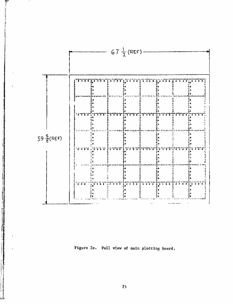
board is maintained by a plotter moi'Storing a high-to-medium altitude airdefense (HIMAD) source of rada: track data. The board is scaled to1:lO),000 for an area of 180 km x 1C0 km. A main plotting board is centeredamo,.g the three boards with a scale of 1:50,000 for an aprroximate divisionarea of 80 km x 70 km. This board is maintained by four plotters. Eachplotter monitors a separate FAAR transmission, dnd then plots the requiredinformation (viz. target identification, location, type, and beadirg), Afriendly plctting board with the some cha-acteristics as the main h oard isused for airspace management "dta whi:h is maintained by an aviationoperations specialist. The Division Air Nan~gement Element (DAME) suppliesthese data consisting oi friendly aviatir;n plans, route structures,identification procedures, aventies of approach, hostile air action, etc.
The plotting is done on one side of the fluorescent edge lit plexi-gl.ass boarda and read from the other. Plotting of heading and alphanumericcharacters is dnne in mirror image to produce the proper orientation whenread from the other side. Each board is •iarked in a SHORAD grid system(Army Air Defense School, 1981; Fallesen, 1983) which consists of 400 gridnames with a code word assigned to each aquare of 10 km x 10 km. Each 10 kmarea is further divided into 1 km increments.
N The information of the three plctting boards is consolidated into acomposite "air picture" and broadca-t on the division air defense earlywarning n"- '..ADEW). The net is implemented by transmitting AM and FM radiosignals ixe radio telephone operator (RIO) is primarily responsible forbroadr..- tiack information. The officer-in-charge (OIC) assists bydire- o and prioritizing information as well as controlling the FAARvlat .
By considering these operations and the associated equipment layout,se,,eral ,eficiencies were identified.
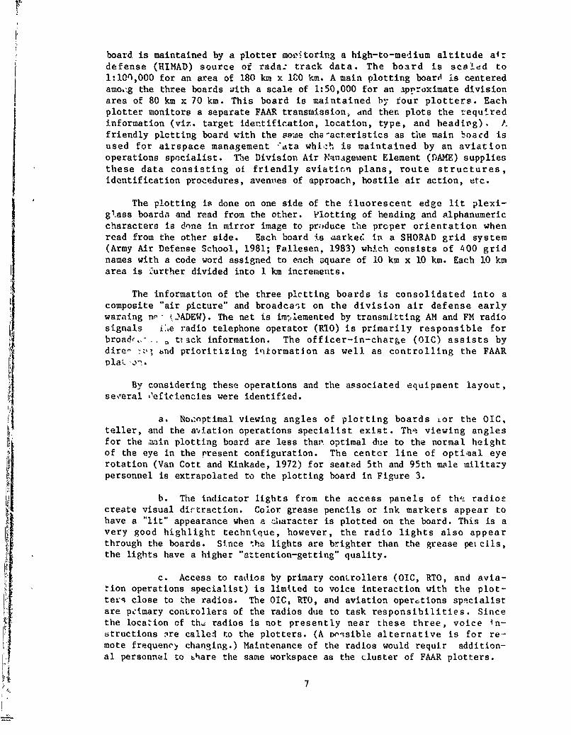
a. Noonptimal viewing angles of plotting boards Lor the OIC0
teller, and the a-viation operations specialist exist. Th'i viewing anglesfor the -ain plotting board are less than. optimal due to the normal heightof the eye in the rresent configuration. The center line of optiaal eyerotation (Van Cott and Kinkade, 1972) for seated 5th and 95th male militarypersonnel is extrapolated to the plotting board in Figure 3.
b. The indicator lights from the access panels of the radioecreate visual dirtraction. Color grease pencils or ink markers appear toII have a "lit" appearance when a citaracter is plotted on the board. This is a
very good highlight technique, however, the radio lights also appearthrough the boards. Since the lights are brighter than the grease pet cils,the lights have a higher "aztention-getting" quality.
c. Access to radios by primary controllers (OIC, RTO, and avia-tion operations specialist) is limited to voice interaction with the plot-texq close to the radios. The OIC, RTO, and aviation opertions spqcialistare peimary controllers of the radios due to task responsibilities. Sincethe location of th, radios is not presently near these three, voice in-6tructions ire called to the plotters. (A pcssible alternative is for re-mote frequency changing.) Maintenance of the radios would requir addition-al personnel to 0hare the same workspace as the cluster of FAAR plotters.
7
3-I'
0 U)
0 w I-_0 (L) 44
0 U0
0)-x0
0) IAWI/ I '
-4IA 4
0 - _ _ _ _ _ _ _ _W I - .1
0/t
-Jo4
I- 00.
000E
_
I--< W0o Z.J
a.>,
w-l
z 0 U
0 0-4N 1

d. Workspace and passage area are Inaufficient for the plotters.There is limited workspace for squatting operation by the plotter thenpassage behind is also required. Woodson (1981) recommends a 36" minimumfor squatting operations and Thomson (1972) recommends a 36" width for oneperson standing ane one person passing (perpendicular) with a 30" minimum.At the two side boards, the workspace problem is (:Ampounded where theboards are near the sides of the van.
e. Ingress/egress for the plotters to and from their stations isinadequate. Either side board (they are hinged to the center board) mustbe moved aside for access to plotting stat ,ns. This can create plottingproblems if the board is in use at the t"'. t. It does not allow for fastexit/entrance as boards are normally secured in place by a spring loadedlever. It is possible to have six plotters (and possibly other personnel)behind the boards at one time. If the need for emergency egress arose, theot-tacle of the bo'erds and the distance to the exit could be criticalfa, •rs.
MODIFIED LAYOUT AND RATIONALE
In additon to the design constraints on page and the preceding listof deficieaicies, the layout was modified to obtain the following designobjectives:
a. Improve viewing by the OC, RTO, and the aviation operationsspecialist to include optimizing viewing distance, height, angle, andminimizing visual distraction.
b. Allow for sit/stand operation by the OIC, RTO, and theaviation onerations specialist.
c. Allow proper ingress/egress to/from stations by all occupantsof the van.
d. Provide recommended workspace/passageway dimensions.
e. Be responsive to anth:opometric dimension of Army personnel.
f. Provide storage space for individual soldier's equipment.
In order to achieve three of these criteria simultaneouely (viz.provide recommended workspace dimensions, ingress/egress, and optimizeviewing angles), the primary change was to turn the orientation of plottingboards and the worktable 900 (Figure 4). The worktable was raised to aheight of 36" to promote sit/stand operation, allow for increased storagespace beneath and to raise the 01C, RTO, and the aviation operationsspecialist to an improved viewing height (Figure 5).
9

Iit
H I * I I
SI " I'' h"
> cI
N 10
-- I i H•.
N o0
.•,F P, NZ
I •.,.4
---. -- •- - ...................
10

'-4a4
00
L '-4
I Wl d
0 ý EI lJ~L-7V
it
'-4)
0.0
a)$4J
00

Ei'' 117 ilk
K
i-je
t
I •I I I I
Figure 4d. Rilfle rack and shelf for soldler's Sear.
12

00
I- z I--
Wc U W-
4 000
zi w
c.c
0-I 4j
-2 &4- - -m 44J0
4A 1/WI
0- w__ _ _ _ _ _ _ _ _ 0 .'4.
- z
*C 0
0: c
4)21-4CI-to
0 I-
co 00
0 t0
N IQ
00 I
13
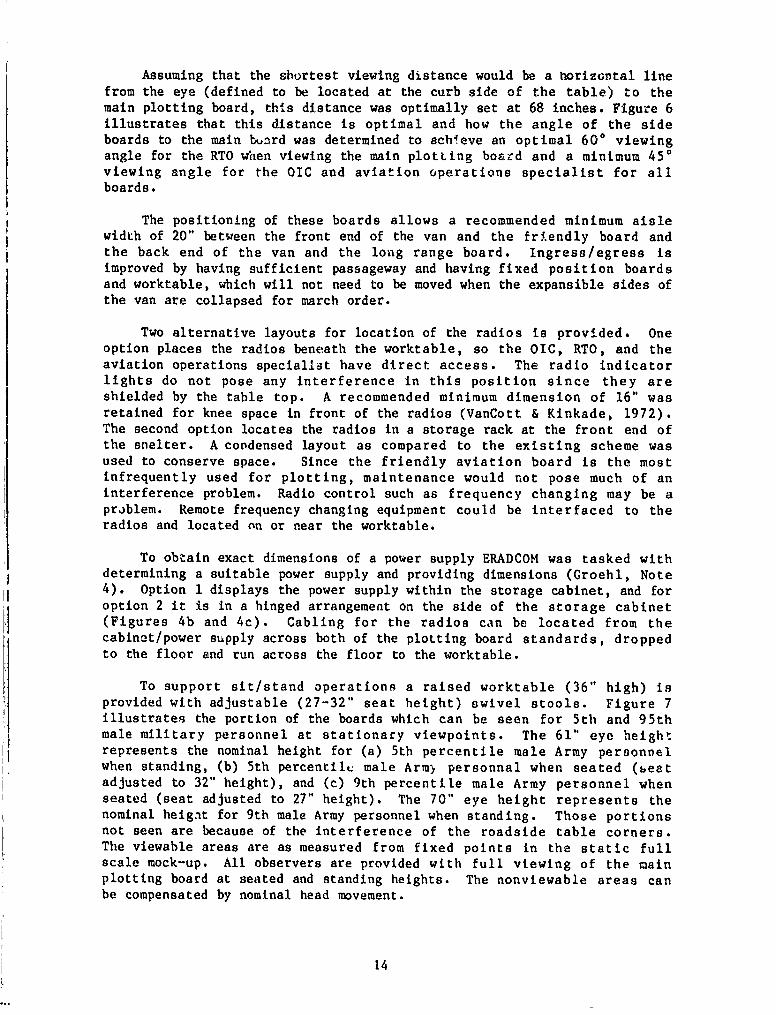
Assuming that the shortest viewing distance would be a horizontal linefrom the eye (defined to be located at the curb side of the table) to themain plotting board, this distance was optimally set at 68 inches. Figure 6illustrates that this distance is optimal and how the angle of the sideboards to the main bunrd was determined to achieve an optimal 600 viewingangle for the RTO when viewing the main plotting bo&rd and a minimum 450viewing angle for the OIC and aviation operations specialist for allboards.
The positioning of these boards allows a recommended minimum aislewidth of 20" between the front end of the van and the friendly board andthe back end of the van and the long range board. Ingress/egress isimproved by having sufficient passageway and having fixed position boardsand worktable, which will not need to be moved when the expansible sides ofthe van are collapsed for march order.
Two alternative layouts for location of the radios is provided. Oneoption places the radios beneath the worktable, so the OIC, RTO, and theaviation operations speciallit have direct access. The radio indicatorlights do not pose any interference in this position since they areshielded by the table top. A recommended minimum dimension of 16" wasretained for knee space in front of the radios (VanCott & Kinkade, 1972).The second option locates the radios in a storage rack at the front end ofthe shelter. A condensed layout as compared to the existing scheme wasused to conserve space. Since the friendly aviation board is the mostinfrequently used for plotting, maintenance would not pose much of aninterference problem. Radio control such as frequency changing may be aproblem. Remote frequency changing equipment could be interfaced to theradios and located on or near the worktable.
To obtain exact dimensions of a power supply ERADCOM was tasked withdetermining a suitable power supply and providing dimensions (Groehl, Note4). Option 1 displays the power supply within the storage cabinet, and foroption 2 it is in a hinged arrangement on the side of the storage cabinet(Figures 4b and 4c). Cabling for the radios can be located from thecabinet/power supply across both of the plotting board standards, dropped
to the floor and run across the floor to the worktable.
To support sit/stand operations a raised worktable (36" high) isprovided with adjustable (27-32" seat height) swivel stools. Figure 7illustrates the portion of the boards which can be seen for 5th and 95thmale military personnel at stationary viewpoints. The 61" eye heightrepresents the nominal height for (a) 5th percentile male Army personnelwhen standing, (b) 5th percentilL male Arm) personnal when seated (beatadjusted to 32" height), and (c) 9th percentile male Army personnel whenseated (seat adjusted to 27" height). The 70" eye height represents thenominal heigat for 9th male Army personnel when standing. Those portionsnot seen are because of the interference of the roadside table corners.The viewable areas are as measured from fixed points in the static fullscale mock-up. All observers are provided with full viewing of the mainplotting board at seated and standing heights. The nonviewable areas canbe compensated by nominal head movement.
14

C
S~64"h-6 ? I
W[ORK TABLE
g OPTIMUM VIEWING AREAOF MAIN PLOTTING BOAR.
._ ._ , .. __.. ....F76 7
I.-76
Note: Angle a 600 (optimum viewing angle).Angle b = 450 (minimum view angle).Point d is the observation center position for the aviation operating
specialist.?oint e is the observation center position for the RTO.Angle c - 1250 and line ef - 68" (determined simultaneously such that
point d would lie within the minimum viewing area of the friendlyaviation board and point e would lie in area g).
Figure 6. Representation. of optimum viewing distance (e to f) and board toboard angle (c).
15

Perspective of
worktable and
plotting boards.
Right side viewing61" eye height.
r -T
1. 4'
Right side viewing70" eye height.
~-\ T
Center viewing61" eye height.
_j
Center viewing70" eye height.
4.o i- 2
Figure 7. Plotcing board occlusion areas due to worktable visual interference
from two viewing positions and 'or two eye heights.
++'+,+ X•:16

An itemized liat of Iernaa. equi~pent and gear was used te design
individual storage 3ace (Table 1). An -.46 rifle rack .c provided in
immediate proximity to the van opening. By storing the rifles in this
locatlon there is posittve, secure placement a&d less chance of scratching
the plxiglass boards, Utllapaible atorage shr.ives have been provided for
holding personal gear, When the sides of the expansible van are to be
collapsed, the hook Il swung to the side and the shelf foldn flat against
the side wall.
TABLE I
EquIpment Lint for ABMOC Personnel
Helmet
BeltSuspendersCanteenFirst Aid PouchAmmunition Pouch (2)
Protective Mask
Field JacketPonchoRain Gear
M16 (.45 caliber pistol)
(Leonard, Note 5)
17

CONCLUSIONS AND RECOMMENDATIONS
The~~~~ ~ .........pc lyot ahw .In F....e 4 an.d 00) providesadesign which alleviates the cited deficiercfes and optimizes the criteriawithin the given constraints. There are considerations to the presentlayout which have not been depicted in any figures.
Blackout curtains could be added co the layout around one door of theentrance without interfering with workspace around the long range board.Also, the modified layout has reduced atorage space for ABMOC supplies,such as maps, wire, markers, etc,; however, additional storage could beadded. This would probably be achieved by using cabinets or racks whichslide or pivot (-s does the power supply) to the unused corners of the van.With the given -.onstraint of plotting board size, there are problemsassociated with multiple plotters who mý!st share the same workspace andsquat or kneel to reach lower portions of the boards. 2 These problems werealleviated by providing increased workspace of 40" behind the main plottingboard. A reconfiguration of the boards may further minimize the problem ofshared workspace.
One considerable change to the present layout was a change in radiolocation. Two alternative radio layout6 were provided; one with the radioplaced bene~ath the table and the other in a separate storage cabinet.Since unde-the-table placement of radios is uncommon and might proveimpractical in operations, an alternative iack mounting was provided.
Following analyses of the M820 workspace and application of basichuman factors design principles, a new workspace layout was designed. Themajor workspace layout consideration was the rotation of plotting boardsand worktable (viewing position) by 90' In the plan view. This basicdesign should provide improved ingress/egress for plotters, allow optimal(but not unobstructed) viewing angles for the RTO, OIC, and the aviationoperation specialist, and provide fixi placement of most layoutcomponents. It is recommended that workspai, layout analyses and conceptssuch as those presented in this report be considered for ABMOC M820shelters in order to provide an improved joldier-machine interface.
2 Continual squatting or kneeling may ca,ije fatique and hence VanCott &K'nkade, 1972, recommend a 32-inch minimal dimension off the floor forupright charting surfaces.
V 18

V4
000
90
19
REFERENCES
1. Fallew..n, J. J. An evaluation of short-ran;e air defense (SHORAD) gridname sets (USAHEL TN 5-83). Aberdeen Proving Ground, MD: US Army HumanEngineering Laboratory, 1983.
2. Putnam, G. H. Force development test and experimentation of enhancedmanual SHORAD control system (MSCS) in Europe: Test report. FortBliss, TX: TRADOC Special Test DirEq,;..orate, November 1981.
3. Schoch, F. MSCS: The future of SPORAD early warning. Air DefenseMaazine, July-September 1982, pp. 27-36.
4. Thomoon, R. M. Design of multi-man-machine work areas. In H.P. VanCott& R. G. Kinkade (Eds.), uiman engineering guide to equipment desig_(rev. ed.). Washington, D.C.: US Government Printing Office, 1972.
5. US Army Air Defense School. Pperations and training: Forward areaalerting radar (FAAR) and taret alerting data display set (TADDS) (FM44-6). Washington, D.C.: US Government Printing Office, 1981.
6. VanCott, H. P., & Kinkadv, R. G. Human engineering guide to equipmentdesign (rev. ed.). Washington, D.C.: US Government Printing Office,1972.
7. Woodson, W. E. Human factors design handbook. New York, NY:McGraw-Hill, 1981.
20

REFERENCE NOTES
1. Fry, C. Ao, & Kurtz, G. L. Trip report: HEL observations of airdefense operations during Reforger 1981 (Germany). Aberdeen ProvingGround, MD: US Army Human Engineering Laboratory, October 1981.
2. Kurtz, G. L., & Fallesen, J. J. Trip report: SHORAD manual C2 evstemFort Lewis, WA. Aberdeen Proving Ground, MD: US Army Human Eng-.,eeringLaboratory, December 1981.
3. Kurtz, G. L., & Smyth, C. C. Trip report: 9th DIVADA higi technologyfield exercise (Yakima, WA). Aberdeen Proving Groupd, AD: US ArmyHuman Engineering Laboratory, May 1982.
4. Groehl, L. Personal communication, .- nuary 1983.
5. Leonard, R. Persona] communication, June 1982.
21

APPENDIX A
PLOTTING BOARD DRAWINGS
23
pn L~p

44
0
VH
0
t:3
24-
I i 6 2 4 6 6 4i l 1 - 6 -2 4 6 6 14 4 7 6 6 1 4 a6 - 4 .$a4 6 24 6 0
4 I.
44
41-- :
-4 4 4 4 s r
-46 1 - : + -ý
59 T(EF 6 6
.4 4 4 4
a -42~ ~ ~ ~ ~ ~ 46 44 0-9
59j(~ F .4- 6 1
252