world journal of engineering research and technologysireesha et al. world journal of engineering...
TRANSCRIPT

Sireesha et al. World Journal of Engineering Research and Technology
www.wjert.org
81
STATCOM BASED REDUCTION OF PQ ISSUES IN MICRO GRID
APPLICATION SYSTEMS
P. Sireesha1*, Meera Shareef
2 and V. Hari Babu
3
1Student (M. Tech), Power Electronics (EEE), Prakasam Engineering College, A.P., India.
2Asistant Professor, E.E.E., Prakasam Engineering College, A.P., India.
3H.O.D., E.E.E., Prakasam Engineering College, A.P., India.
Article Received on 06/10/2016 Article Revised on 26/10/2016 Article Accepted on 15/11/2016
ABSTRACT
The increasing use of power electronic based loads such as adjustable
Speed drives, Switch mode power supplies, etc to improve system
efficiency and Controllability is increasing concern for harmonic
distortion levels in end use facilities and on overall power system. The
application of passive tuned filters creates new system resonances,
which are dependent on specific system conditions. In addition, passive filters often need to
be significantly overrated to account for possible harmonic absorption from power system.
Passive filter ratings must be coordinated with reactive power requirements of the loads and it
is often difficult to design the filter to avoid leading power factor Operation for some load
conditions. There are different ways to enhance power quality problems in transmission and
distribution systems. Among these, the D-STATCOM is one of the most effective devices. A
new PWM-based control scheme has been implemented to control the electronic valves in the
DSTATCOM. The D-STATCOM has additional capability to sustain reactive current at low
voltage, and can be developed as a voltage and frequency support by replacing capacitors
with batteries as energy storage. STATCOM is often used in transmission system. When it is
used in distribution system, it is called D-STATCOM in Distribution system). D-STATCOM
is a key FACTS controller and it utilizes power electronics to solve many power quality
problems commonly faced by distribution systems. Potential applications of D-STATCOM
include power factor correction, voltage regulation, load balancing and harmonic reduction.
Comparing with the SVC, the D-STATCOM has quicker response time and compact
ISSN 2454-695X Research Article wjert, 2016, Vol. 2, Issue 6, 81 -95
World Journal of Engineering Research and Technology
WJERT
www.wjert.org SJIF Impact Factor: 3.419
*Corresponding Author
P. Sireesha
Student (M. Tech), Power
Electronics (EEE),
Prakasam Engineering
College, A.P., India
Sireesha et al. World Journal of Engineering Research and Technology
www.wjert.org
82
structure. It is expected that the D-STATCOM will replace the roles of SVC in nearly future
D-STATCOM can be effectively utilized to improve the quality of power supplied to the
customers. The performance of the wind turbine and thereby power quality are determined on
the basis of measurements and the norms followed according to the guideline specified in
International Electro-technical Commission standard, IEC-61400. The influence of the wind
turbine in the grid system concerning the power quality measurements are-the active power,
reactive power, variation of voltage, flicker, harmonics, and electrical behaviour of switching
operation and these are measured according to national/international guidelines. The paper
study demonstrates the power quality problem solution due to installation of wind turbine
with the grid. This paper is extension for the power quality improvement with THD
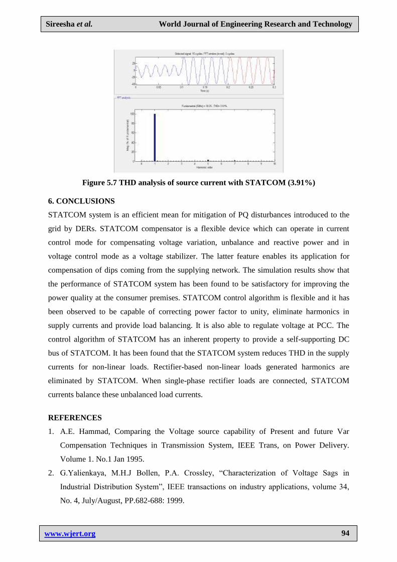
reduction. THD is reduced to 3.91% from 11.2%.
Index Terms: Statcom, bang controller, THD, bess.
1. INTRODUCTION
One of the main problems in wind energy generation is the connection to the grid. Injection
of wind power into the grid affects the power quality resulting in poor performance of the
system. The wind energy system faces frequently fluctuating voltage due to the nature of
wind and introduction of harmonics into the system. Injection of the wind power into an
electric grid affects the power quality. The performance of the wind turbine and thereby
power quality are determined on the basis of measurements and the norms followed
according to the guideline specified in International Electro-technical Commission standard,
IEC-61400. The influence of the wind turbine in the grid system concerning the power
quality measurements are-the active power, reactive power, variation of voltage, flicker,
harmonics, and electrical behavior of switching operation and these are measured according
to national/international guidelines. While fossil fuels will be the main fuels for thermal
power, there is a fear that they will get exhausted eventually in the next century. To have
sustainable growth and social progress, it is necessary to meet the energy need by utilizing
the renewable energy resources like wind, biomass, hydro, co-generation etc. In sustainable
energy system, energy conservation and the use of renewable source are the key paradigm.
The need to integrate the renewable energy like wind energy into power system is to
minimize the environmental impact on conventional plant.[7]
With the help of special
collectors, we can capture a part of this energy and put it to use for our electrical power
supply needs. As long as sunlight, water and wind continue to flow and trees and other plants
Sireesha et al. World Journal of Engineering Research and Technology
www.wjert.org
83
continue to grow, we have access to a ready of supply of energy. In this proposed scheme
Static Compensator (STATCOM) is connected at a point of common coupling with a battery
energy storage system (BESS) to mitigate the power quality issues. The battery energy
storage is integrated to sustain the real power source under fluctuating wind power. The
STATCOM control scheme for the grid connected wind energy generation system for power
quality improvement is simulated using MATLAB/SIMULINK in power system block set.
The effectiveness of the proposed scheme relieves the main supply source from the reactive
power demand of the load and the induction generator. It is also having capability of
harmonic elimination and load balancing. The proposed STATCOM control scheme for grid
connected wind energy generation for power quality improvement has following objectives.
1) Unity power factor at the source side as well as Reactive power support from STATCOM
2) to wind generator and load.
3) Simple bang-bang controller for STATCOM to achieve fast dynamic response. The report
is organized as follows.
4) Reduction in THD in source current which makes other load on line to be safe.
2. INTERNATIONAL ELECTROMECHANICAL COMISSION STANDARDS
The guidelines are provided for measurement of power quality of wind turbine. The
International standards are developed by the working group of Technical Committee-88 of
the International Electro-technical Commission (IEC), IEC standard 61400-21, describes the
procedure for determining the power quality characteristics of the wind turbine.[8]
The
standard norms are specified.
1) IEC 61400-21: Wind turbine generating system, part- 21. Measurement and Assessment
of power quality characteristic of grid connected wind turbine
2) IEC 61400-13: Wind Turbine measuring procedure in determining the power behavior.
978-1.
3) IEC 61400-3-7: Assessment of emission limits for fluctuating load IEC 61400-12: Wind
Turbine performance. The data sheet with electrical characteristic of wind turbine
provides the base for the utility assessment regarding a grid connection.
Sireesha et al. World Journal of Engineering Research and Technology
www.wjert.org
84
2.1 FLUCTUATION IN VOLTAGE
The voltage variation issue results from the wind velocity and generator torque. The voltage
variation is directly related to real and reactive power variations. The voltage variation is
commonly classified as under:
I. Voltage Sag/Voltage Dips.
II. Voltage Swells.
III. Short Interruptions.
IV. Long duration voltage variation.
The voltage flicker issue describes dynamic variations in the network caused by wind turbine
or by varying loads. Thus the power fluctuation from wind turbine occurs during continuous
operation. The amplitude of voltage fluctuation depends on grid strength, network
impedance, and phase-angle and power factor of the wind turbines. It is defined as a
fluctuation of voltage in a frequency 10--35 Hz. The IEC 61400-4-15 specifies a flicker meter
that can be used to measure flicker directly.
2.2 HARMONICS
The harmonic results due to the operation of power electronic converters. The harmonic
voltage and current should be limited to the acceptable level at the point of wind turbine
connection to the network. To ensure the harmonic voltage within limit, each source of
harmonic current can allow only a limited contribution, as per the IEC-61400-36 guideline.
The rapid switching gives a large reduction in lower order harmonic current compared to the
line commutated converter, but the output current will have high frequency current and can
be easily filter out.
2.3 WIND TURBINE LOCATION IN POWER SYSTEM
The way of connecting the wind generating system into the power system highly influences
the power quality. Thus the operation and its influence on power system depend on the
structure of the adjoining power network.
2.4 SELF EXCITATION OF WIND TURBINE GENERATING SYSTEM
The self excitation of wind turbine generating system (WTGS) with an asynchronous
generator takes place after disconnection of wind turbine generating system (WTGS) with
local load. The risk of self excitation arises especially when WTGS is equipped with
compensating capacitor. The capacitor connected to induction generator provides reactive
Sireesha et al. World Journal of Engineering Research and Technology
www.wjert.org
85
power compensation. However the voltage and frequency are determined by the balancing of
the system. The disadvantages of self excitation are the safety aspect and balance between
real and reactive power.
2.5 ISSUES OF POWER QUALITY PROBLEMS
The voltage variation, flicker, harmonics causes the malfunction of equipments namely
microprocessor based control system, programmable logic controller; adjustable speed drives,
flickering of light and screen. It may leads to tripping of contractors, tripping of protection
devices, stoppage of sensitive equipments like personal computer, programmable logic
control system and may stop the process and even can damage of sensitive equipments. Thus
it degrades the power quality in the grid.
2.6 INTEGRATION OF GRID RULE
The American Wind Energy Association (AWEA) led the effort in the united state for
adoption of the grid code for the interconnection of the wind plants to the utility system. The
rules for realization of grid operation of wind generating system at the distribution network
are defined as-per IEC-61400-21. The grid quality characteristics and limits are given for
references that the customer and the utility grid may expect. According to Energy-Economic
Law, the operator of transmission grid is responsible for the organization and operation of
interconnected system.
2.7 VOLTAGE SWELL
The voltage rise (u) at the point of common coupling can be approximated as a function of
maximum apparent power Smax of the turbine, the grid impedances R and X at the point of
common coupling and the phase angle θ [2], given in as follows.
……..2.1
Where Δu is voltage rise, U is the nominal voltage of the grid. The Limiting voltage rise
value is less than 2%
2.8 VOLTAGE SAGS
The voltage dips is due to start up of wind turbine and it causes a sudden reduction of
voltage. It is the relative %voltage change due to switching operation of wind turbine. The
decrease of nominal voltage change is given in equation as follows.
……………… 2.2
Sireesha et al. World Journal of Engineering Research and Technology
www.wjert.org
86
Where d is relative voltage change, Sn is rated apparent power, Sk is short circuit apparent
power and ku is sudden voltage reduction factor. The acceptable voltage dips limiting value
is less than or equal to 3%.
2.8 HARMONICS
The harmonic distortion is assessed for variable speed turbine with a electronic power
converter at the point of common connection. The total harmonic voltage distortion of
voltage is given as in equation as follows
……….. 2.3
Where Vn is the nth harmonic voltage V1 is the fundamental frequency voltage. The THD
limit for 132 kV is less than 3%. The current THD can also be estimated similarly and the
limit for 132 kV is less than 5%.
2.9 GRID FREQUENCY
The grid frequency in India is specified in the range of 47.5–51.5 Hz, for wind farm
connection. The wind farm shall able to withstand change in frequency up to 0.5Hz/s.
3. PROPOSED CONCEPT
The STATCOM based current control voltage source inverter injects the current into the grid
in such a way that the source current are harmonic free and their phase angle with respect to
source voltage has a desired value. The injected current will cancel out the reactive part and
harmonic part of the load and induction generator current, thus it improves the power factor
and the power quality. To accomplish these goals, the grid voltages are sensed and are
synchronized in generating the current command for the inverter. The proposed grid
connected system is implemented for power quality improvement at point of common
coupling (PCC), as shown in Fig. 3.6. The grid connected system in Fig. 3.6, consists of wind
energy generation system and battery energy storage system with STATCOM.
3.1 WIND ENERGY GENERATING SYSTEM
In this configuration, wind generations are based on constant speed topologies with pitch
control turbine. The induction generator is used in the proposed scheme because of its
simplicity, it does not require a separate field circuit, it can accept constant and variable
Sireesha et al. World Journal of Engineering Research and Technology
www.wjert.org
87
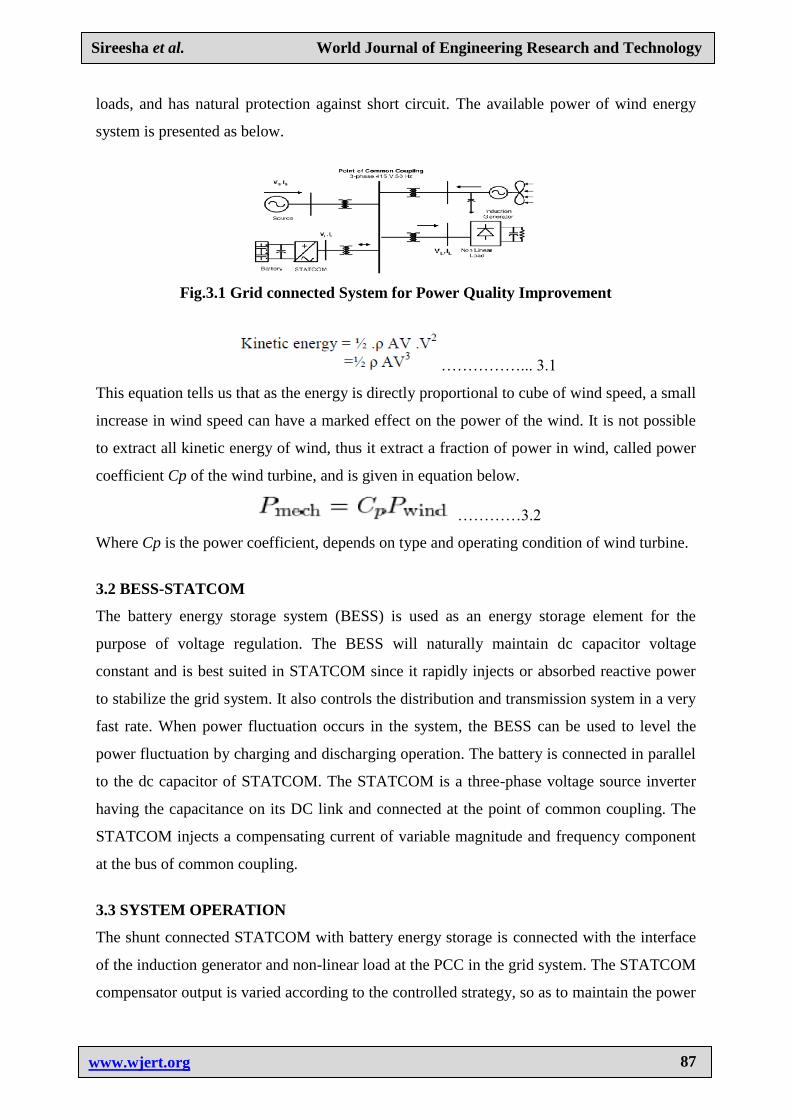
loads, and has natural protection against short circuit. The available power of wind energy
system is presented as below.
Fig.3.1 Grid connected System for Power Quality Improvement
……………... 3.1
This equation tells us that as the energy is directly proportional to cube of wind speed, a small
increase in wind speed can have a marked effect on the power of the wind. It is not possible
to extract all kinetic energy of wind, thus it extract a fraction of power in wind, called power
coefficient Cp of the wind turbine, and is given in equation below.
…………3.2
Where Cp is the power coefficient, depends on type and operating condition of wind turbine.
3.2 BESS-STATCOM
The battery energy storage system (BESS) is used as an energy storage element for the
purpose of voltage regulation. The BESS will naturally maintain dc capacitor voltage
constant and is best suited in STATCOM since it rapidly injects or absorbed reactive power
to stabilize the grid system. It also controls the distribution and transmission system in a very
fast rate. When power fluctuation occurs in the system, the BESS can be used to level the
power fluctuation by charging and discharging operation. The battery is connected in parallel
to the dc capacitor of STATCOM. The STATCOM is a three-phase voltage source inverter
having the capacitance on its DC link and connected at the point of common coupling. The
STATCOM injects a compensating current of variable magnitude and frequency component
at the bus of common coupling.
3.3 SYSTEM OPERATION
The shunt connected STATCOM with battery energy storage is connected with the interface
of the induction generator and non-linear load at the PCC in the grid system. The STATCOM
compensator output is varied according to the controlled strategy, so as to maintain the power
Sireesha et al. World Journal of Engineering Research and Technology
www.wjert.org
88
quality norms in the grid system. The current control strategy is included in the control
scheme that defines the functional operation of the STATCOM in the power system. A single
STATCOM using insulated gate bipolar transistor is proposed to have a reactive power
support, to the induction generator and to the nonlinear load in the grid system. The main
block diagram of the system operational scheme is shown in Fig. 3.1
3.4 CONTROL SCHEME
The control scheme approach is based on injecting the currents into the grid using “bang-
bang controller.” The controller uses a hysteresis current controlled technique. Using such
technique, the controller keeps the control system variable between boundaries of hysteresis
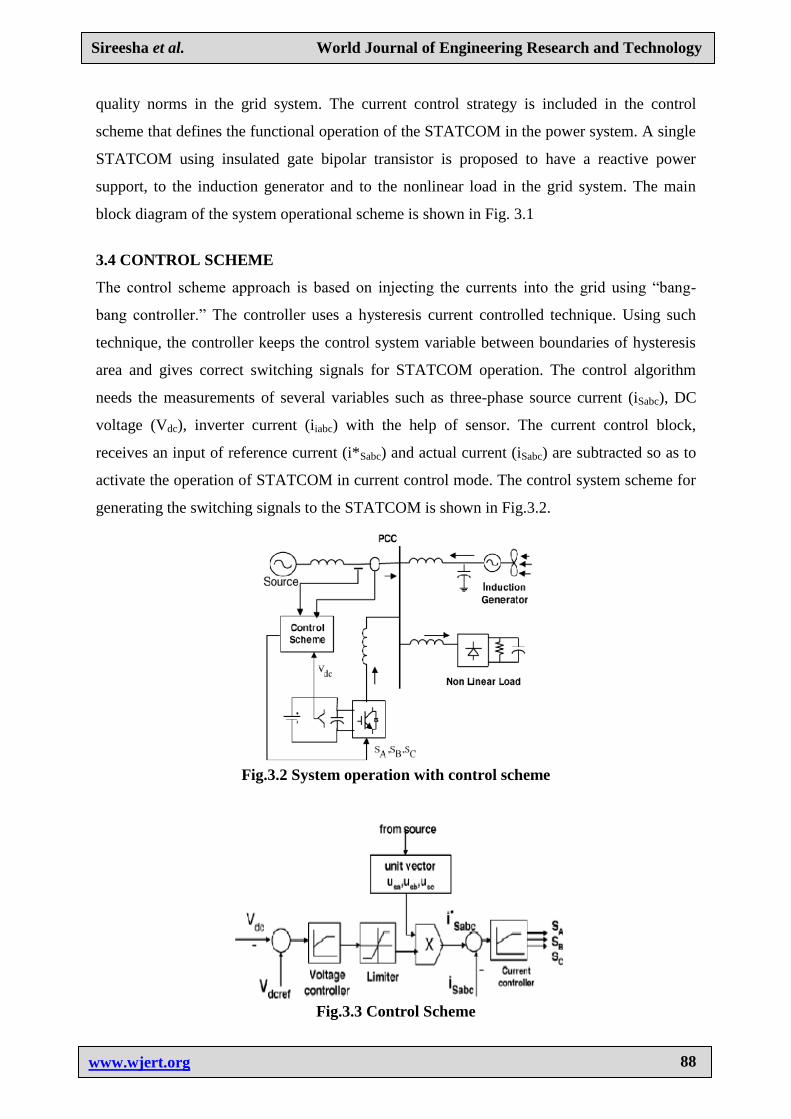
area and gives correct switching signals for STATCOM operation. The control algorithm
needs the measurements of several variables such as three-phase source current (iSabc), DC
voltage (Vdc), inverter current (iiabc) with the help of sensor. The current control block,
receives an input of reference current (i*Sabc) and actual current (iSabc) are subtracted so as to
activate the operation of STATCOM in current control mode. The control system scheme for
generating the switching signals to the STATCOM is shown in Fig.3.2.
Fig.3.2 System operation with control scheme
Fig.3.3 Control Scheme
Sireesha et al. World Journal of Engineering Research and Technology
www.wjert.org
89
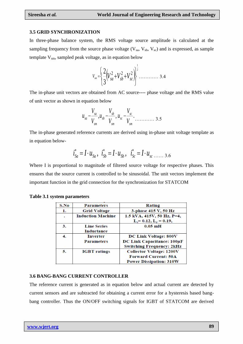
3.5 GRID SYNCHRONIZATION
In three-phase balance system, the RMS voltage source amplitude is calculated at the
sampling frequency from the source phase voltage (Vsa, Vsb, Vsc) and is expressed, as sample
template Vsm, sampled peak voltage, as in equation below
222
3
2 2
1
scsbsaV VVVsm ………… 3.4
The in-phase unit vectors are obtained from AC source---- phase voltage and the RMS value
of unit vector as shown in equation below
.,,sm
scsc
sm
sbsb
sm
sasa
V
Vu
V
Vu
V
Vu
………… 3.5
The in-phase generated reference currents are derived using in-phase unit voltage template as
in equation below-
scScSbSbSaSa uIiuIiuIi ,, …… 3.6
Where I is proportional to magnitude of filtered source voltage for respective phases. This
ensures that the source current is controlled to be sinusoidal. The unit vectors implement the
important function in the grid connection for the synchronization for STATCOM
Table 3.1 system parameters
3.6 BANG-BANG CURRENT CONTROLLER
The reference current is generated as in equation below and actual current are detected by
current sensors and are subtracted for obtaining a current error for a hysteresis based bang-
bang controller. Thus the ON/OFF switching signals for IGBT of STATCOM are derived
Sireesha et al. World Journal of Engineering Research and Technology
www.wjert.org
90
from hysteresis controller. The switching function S A for phase „a‟ is expressed as in
equation below. When Isa < (I*sa - HB), SA = 0 and when Isa > (I*sb - HB) , SA = 1
Where HB is a hysteresis current-band, similarly the switching function SB , SC can be
derived for phases b and c respectively.
3.7 SYSTEM PERFORMANCE
The proposed control scheme is simulated using SIMULINK in power system block set. The
system parameter for given system is given Table I. The system performance of proposed
system under dynamic condition is also presented.
3.8 VOLTAGE SOURCE CURRENTCONTROL INVERTER OPERATION
The three phase injected current into the grid from STATCOM will cancel out the distortion
caused by the nonlinear load and wind generator. The IGBT based three-phase inverter is
connected to grid through the transformer. The generation of switching signals from
reference current is simulated within hysteresis band of 0.08. The choice of narrow hysteresis
band switching in the system improves the current quality.
4. MATLAB MODELLING
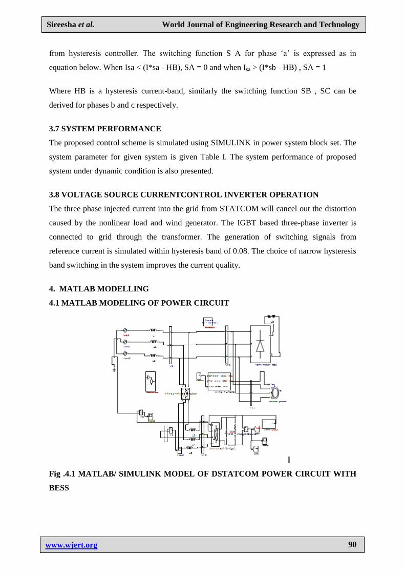
4.1 MATLAB MODELING OF POWER CIRCUIT
Fig .4.1 MATLAB/ SIMULINK MODEL OF DSTATCOM POWER CIRCUIT WITH
BESS
Sireesha et al. World Journal of Engineering Research and Technology
www.wjert.org
91
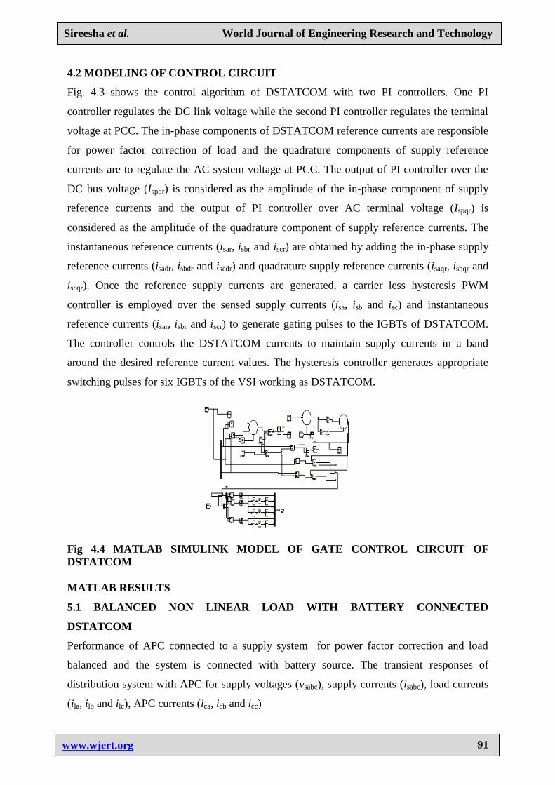
4.2 MODELING OF CONTROL CIRCUIT
Fig. 4.3 shows the control algorithm of DSTATCOM with two PI controllers. One PI
controller regulates the DC link voltage while the second PI controller regulates the terminal
voltage at PCC. The in-phase components of DSTATCOM reference currents are responsible
for power factor correction of load and the quadrature components of supply reference
currents are to regulate the AC system voltage at PCC. The output of PI controller over the
DC bus voltage (Ispdr) is considered as the amplitude of the in-phase component of supply
reference currents and the output of PI controller over AC terminal voltage (Ispqr) is
considered as the amplitude of the quadrature component of supply reference currents. The
instantaneous reference currents (isar, isbr and iscr) are obtained by adding the in-phase supply
reference currents (isadr, isbdr and iscdr) and quadrature supply reference currents (isaqr, isbqr and
iscqr). Once the reference supply currents are generated, a carrier less hysteresis PWM
controller is employed over the sensed supply currents (isa, isb and isc) and instantaneous
reference currents (isar, isbr and iscr) to generate gating pulses to the IGBTs of DSTATCOM.
The controller controls the DSTATCOM currents to maintain supply currents in a band
around the desired reference current values. The hysteresis controller generates appropriate
switching pulses for six IGBTs of the VSI working as DSTATCOM.
Fig 4.4 MATLAB SIMULINK MODEL OF GATE CONTROL CIRCUIT OF
DSTATCOM
MATLAB RESULTS
5.1 BALANCED NON LINEAR LOAD WITH BATTERY CONNECTED
DSTATCOM
Performance of APC connected to a supply system for power factor correction and load
balanced and the system is connected with battery source. The transient responses of
distribution system with APC for supply voltages (vsabc), supply currents (isabc), load currents
(ila, ilb and ilc), APC currents (ica, icb and icc)
Sireesha et al. World Journal of Engineering Research and Technology
www.wjert.org
92
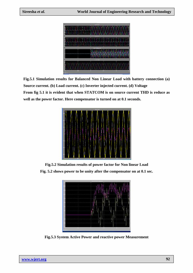
Fig.5.1 Simulation results for Balanced Non Linear Load with battery connection (a)
Source current. (b) Load current. (c) Inverter injected current. (d) Voltage
From fig 5.1 it is evident that when STATCOM is on source current THD is reduce as
well as the power factor. Here compensator is turned on at 0.1 seconds.
Fig.5.2 Simulation results of power factor for Non linear Load
Fig. 5.2 shows power to be unity after the compensator on at 0.1 sec.
Fig.5.3 System Active Power and reactive power Measurement Fig.4.4
Simulati
on results
power
factor for
Non
linear
Load
Sireesha et al. World Journal of Engineering Research and Technology
www.wjert.org
93
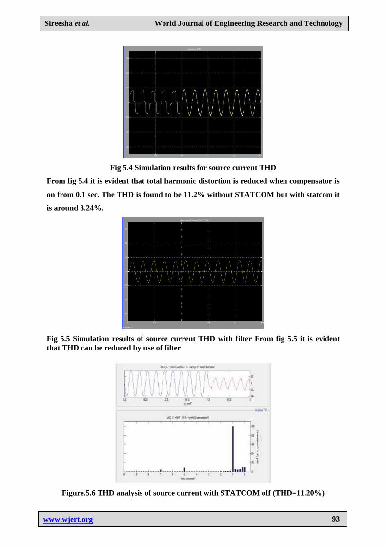
Fig 5.4 Simulation results for source current THD
From fig 5.4 it is evident that total harmonic distortion is reduced when compensator is
on from 0.1 sec. The THD is found to be 11.2% without STATCOM but with statcom it
is around 3.24%.
Fig 5.5 Simulation results of source current THD with filter From fig 5.5 it is evident
that THD can be reduced by use of filter
Figure.5.6 THD analysis of source current with STATCOM off (THD=11.20%)
Sireesha et al. World Journal of Engineering Research and Technology
www.wjert.org
94
Figure 5.7 THD analysis of source current with STATCOM (3.91%)
6. CONCLUSIONS
STATCOM system is an efficient mean for mitigation of PQ disturbances introduced to the
grid by DERs. STATCOM compensator is a flexible device which can operate in current
control mode for compensating voltage variation, unbalance and reactive power and in
voltage control mode as a voltage stabilizer. The latter feature enables its application for
compensation of dips coming from the supplying network. The simulation results show that
the performance of STATCOM system has been found to be satisfactory for improving the
power quality at the consumer premises. STATCOM control algorithm is flexible and it has
been observed to be capable of correcting power factor to unity, eliminate harmonics in
supply currents and provide load balancing. It is also able to regulate voltage at PCC. The
control algorithm of STATCOM has an inherent property to provide a self-supporting DC
bus of STATCOM. It has been found that the STATCOM system reduces THD in the supply
currents for non-linear loads. Rectifier-based non-linear loads generated harmonics are
eliminated by STATCOM. When single-phase rectifier loads are connected, STATCOM
currents balance these unbalanced load currents.
REFERENCES
1. A.E. Hammad, Comparing the Voltage source capability of Present and future Var
Compensation Techniques in Transmission System, IEEE Trans, on Power Delivery.
Volume 1. No.1 Jan 1995.
2. G.Yalienkaya, M.H.J Bollen, P.A. Crossley, “Characterization of Voltage Sags in
Industrial Distribution System”, IEEE transactions on industry applications, volume 34,
No. 4, July/August, PP.682-688: 1999.
Sireesha et al. World Journal of Engineering Research and Technology
www.wjert.org
95
3. Haque, M.H., “Compensation Of Distribution Systems Voltage sags by DVR and D-
STATCOM”, Power Tech Proceedings, 2001 IEEE Porto, Volume 1, PP.10-13,
September 2001.
4. Anaya-Lara O, Acha E., “Modeling and Analysis Of Custom Power Systems by
PSCAD/EMTDC”, IEEE Transactions on Power Delivery, Volume 17, Issue: 2002,
Pages: 266-272.
5. Bollen, M.H.J.,”Voltage sags in Three Phase Systems”, Power Engineering Review,
IEEE, Volume 21, Issue :9, September 2001; PP: 11-15.
6. M.Madrigal, E.Acha., “Modelling OF Custom Power Equipment Using Harmonics
Domain Techniques”,IEEE 2000.
7. R.Meinski, R.Pawelek and I.Wasiak, “Shunt Compensation For Power Quality
Improvement Using a STATCOM controller Modelling and Simulation”, IEEE Proce,
Volume 151, No. 2, March 2004.
8. J.Nastran , R. Cajhen, M. Seliger, and P.Jereb,”Active Power Filters for Nonlinear AC
loads, IEEE Trans.on Power Electronics Volume 9, No.1, PP: 92-96, Jan 2004.
9. L.A.Moran, J.W. Dixon , and R.Wallace, A Three Phase Active Power Filter with fixed
Switching Frequency For Reactive Power and Current Harmonics Compensation, IEEE
Trans. On Industrial Electronics. Volume 42, PP: 402-8, August 1995.
10. L.T. Moran ,P.D Ziogas, and G.Joos , Analysis and Design Of Three Phase Current
source solid State Var Compensator, IEEE Trans, on Indutry Applications. Volume 25,
No.2, 1989; PP: 356-65.