wpi replacement to kaven hall: structural design
TRANSCRIPT

MQP LDA-1901
WPI Replacement to Kaven Hall:
Structural Design
A Major Qualifying Project Submitted to the Faculty of Worcester
Polytechnic Institute in Partial Fulfillment of the requirements for the
Bachelor of Science Degree
By:
Laurence Cafaro, Nicholas Day, James Loring, & Eric Schroeder
DATE
Advisor:
Professor Leonard Albano
This report represents work of WPI undergraduate students submitted to the faculty as evidence of a
degree requirement. WPI routinely publishes these reports on its web site without editorial or peer
review. For more information about the projects program at WPI, see
http://www.wpi.edu/Academics/Projects.

MQP LDA-1901
i
Abstract Kaven Hall has housed the Civil and Environmental Engineering Department for over 60
years. Growing class sizes and a lack of technology in meeting spaces demand a new CEE
building. The scope of this project includes the design of a functional floor plan to maximize
square footage and to limit cost. The design explores the possibilities of steel and reinforced
concrete framing to decide which framing method best fits the goal of the project.

MQP LDA-1901
ii
Capstone Design Statement To complete the requirements produced by the Accreditation Board for Engineering and
Technology (ABET) for a Capstone Design experience, numerous realistic constraints must be
thoroughly evaluated during the design process. This project addresses constructability,
environmental, sustainability, social, economic, health and safety, and ethics. Each of these
constraints is described below.
Constructability: Constructability is an important consideration to be aware of throughout the design
process. If a design presented is challenging to construct, then there could be a loss in materials
and time to redesign the structure. The team’s goal was to make the new Kaven Hall easily
buildable. Standard beam and column sizes are specified for ease of construction and
affordability. In the reinforced concrete design alternative, the beams, columns, and floor slabs
are designed to have only a few different sizes to limit the amount of formwork needed for the
job, which also lowers the cost of construction.
Environmental: When working with an old building, such as Kaven Hall, there are a lot of environmental
issues to be concerned with. Building materials, such as lead paint and asbestos tiles or
insulations, are some of the critical elements that should be monitored as the old building is torn
down. Water runoff is not impacted in this design since the new building foot print will not be
much bigger than the existing layout. Runoff was accounted for in the building process and
handled appropriately with erosion control.
Sustainability: Sustainability has been a growing topic over the last 20 years and for WPI as a growing
campus in an urban area. WPI needs a building that is durable and can last another 60 plus years
with minimal maintenance. Producing the most efficient design and limiting the unnecessary
resources used was another way that sustainability was encompassed in the final design.
Social: A building on any campus must be socially accepted by its users for it to be efficiently
used. Surveys were the main tool used to collect the needs of the students and faculty. Ideally,
the professors will now have class rooms that adequately meet their needs. The building will be

MQP LDA-1901
iii
more accessible for all students, with ADA Compliant rooms, and the addition of an elevator.
The facilities staff will enjoy working in this building as it is tied into the loading dock already
present at the base of Fuller Labs with easy access to the elevator. This will help the custodial
staff to facilitate the distribution of paper goods and cleaning products and for easy removal of
trash and recyclables.
Economic: Although economic analysis of the proposed building focused mainly on the structural
components, there was an estimated allowance for other elements of the building to understand
the total cost of the project. Cost is an important consideration since projects are funded by WPI,
and the Board of Trustees will want the most economical design that meets their needs. This cost
estimate was compiled using similar construction projects completed by WPI in the past.
Health and Safety: Health and safety need to be considered for the duration of the project, especially during
the construction period. The United States Department of Labor states that in 2016 that there
were more than 14 deaths a day (United, 2018). Accident rates can be reduced by having the
majority of the components pre-fabricated by manufacturers at their warehouse. Long-term
safety factors that have been evaluated are snow load, occupancy load and fire restrictions to
name a few. To do this, the Massachusetts Building Code (780 CMR), International Building
Code (IBC 2015), American Concrete Institute (ACI 318-19), American Institute of Steel
Construction (AISC 2016), and The American Society of Civil Engineers Standards (ASCE 7-
10) were utilized to make sure all safety requirements were met.
Ethics: When it comes to ethics, proper decisions must always be made based on building codes,
OSHA regulations, and technical competence. This ensures that Kaven Hall is designed and built
ethically and complies with all the required provisions. Understanding the appropriate licensure
requirements for structural design gives us, the design team, insight and ethical values when it
comes to executing this project. Provisions and regulations must always be followed and should
never be abused, even if there may be any potential loopholes. Building quality and the safety of
the occupants are the most important concerns when it comes to design and construction.

MQP LDA-1901
iv
Licensure Statement In the world of civil engineering obtaining licensure is the mark of being a professional
and is the standard in todays’ society. Only a licensed engineer may prepare, sign, seal, and
submit engineering work and drawings to a public authority for approval. Professional Engineers
(PEs) are also responsible for the work of others in the engineering field, making sure that they
follow high ethical standards of practice. Obtaining licensure is necessary for engineers who are
aspiring to hold upper-level management positions in a civil engineering firm.
Obtaining licensure is a major milestone in the career of any engineer and is very
rewarding. However, there is a level of difficulty that is involved with it, and it does take a
significant amount of time to fulfill all the requirements necessary. To obtain licensure, aspiring
engineers must first graduate from a four-year university engineering program accredited by
EAC/ABET. Following graduation, engineers must take and pass the Fundamentals of
Engineering Exam (FE). This is a 6-hour long exam that consists of 110 multiple choice
questions that cover the basics learned throughout an engineer’s college career. Topics include
mathematics, statics, structural analysis, chemistry, and surveying just to name a few.
Once the FE Exam is passed, an aspiring engineer is now recognized as an Engineer-In-
Training (EIT). EIT’s must then complete four years of work experience under the supervision of
a Professional Engineer. After four years of experience are completed, an EIT can then register
for the Principles and Practice Engineering Exam (PE). This exam lasts 8-hours and consists of
80 multiple choice questions. The PE exam is based on which discipline of civil engineering an
individual wishes to practice in and in which state they want to be licensed. Each state has a
different set of standards and qualifications.
Aspiring engineers may also register and take the Structural Engineering Exam also
known as the “SE”. This exam is a 16-hour long test that tests for the competency in the field of
structural engineering. The SE exam is designed for engineers who practice in jurisdictions that
license structural engineers separately from other professional engineers. This 16-hour exam uses
separate gravity and lateral components to test one’s ability to safely design buildings or bridges,
especially in areas of high seismicity and high wind.
In the practicing world of civil engineering it is necessary for an engineer to obtain the
appropriate licensure in his/her discipline. Through the numerous amounts of structural

MQP LDA-1901
v
calculations and designs a licensed engineer works to ensure the safety of those who interact
with and occupy a building or structure.

vi
Table of Contents Abstract .................................................................................................................................................. i
Capstone Design Statement ................................................................................................................... ii
Constructability: ................................................................................................................................ ii
Environmental: .................................................................................................................................. ii
Sustainability: .................................................................................................................................... ii
Social: ................................................................................................................................................. ii
Economic: ......................................................................................................................................... iii
Health and Safety: ............................................................................................................................ iii
Ethics: ............................................................................................................................................... iii
Licensure Statement ............................................................................................................................. iv
Table of Figures:................................................................................................................................... ix
Table of Tables: .................................................................................................................................... ix
1.0 Introduction ..................................................................................................................................... 1
2.0 Background ...................................................................................................................................... 2
2.1 Construction Materials ................................................................................................................ 2
2.1.1 Concrete ................................................................................................................................ 2
2.1.2 Steel ....................................................................................................................................... 3
2.2 Design Tools ................................................................................................................................. 4
2.2.1 Revit ....................................................................................................................................... 4
2.2.2 RAM Structural System ........................................................................................................ 5
2.2.3 Microsoft Excel and Tekla’s TEDDs .................................................................................... 5
2.2.4 Primavera .............................................................................................................................. 6
2.3 Design Parameters ....................................................................................................................... 6
3.0 Methodology .................................................................................................................................... 8
3.1 Objective 1: Develop an architectural program to create and compare layouts based on
community sentiment, the current condition of the building, and academic necessity. ............... 8
3.2 Objective 2: Design a building frame with steel and concrete alternatives based on gravity
and lateral loads. ............................................................................................................................ 9
3.3 Objective 3: Determine the cost effectiveness of each building frame and decide the best
option for the building. ................................................................................................................ 10
4.0 Results ............................................................................................................................................ 11
4.1 Objective 1 Results ..................................................................................................................... 11
4.1.2 Criteria for New Design .......................................................................................................... 14

vii
4.1.2.1 Site constraints ................................................................................................................. 14
4.1.2.2 Recommended Spaces and Functional Areas .................................................................. 16
4.1.2.3 Occupancy and Egress ..................................................................................................... 16
4.1.3 Alternative Layouts................................................................................................................. 17
4.1.3.1 T-Shape ............................................................................................................................. 17
4.1.3.2 C-Shape ............................................................................................................................ 18
4.1.3.3 I-Shape .............................................................................................................................. 19
4.1.3.4 Recommended Layout ...................................................................................................... 19
4.2 Objective 2 Results ........................................................................................................................ 22
4.2.1 Design Loads and Load Combinations ............................................................................... 22
4.2.2 Structural Steel Design........................................................................................................ 22
4.2.3 Reinforced Concrete Design ............................................................................................... 24
4.2.4 Design for Lateral Loads .................................................................................................... 28
4.2.5 Slab on Grade and Foundation Design ............................................................................... 29
4.3 Objective 3 Results ........................................................................................................................ 30
4.3.1 Cost Estimate ...................................................................................................................... 30
4.3.2 Schedule ............................................................................................................................... 31
5.0 Conclusions and Recommendations .............................................................................................. 33
6.0 Bibliography .................................................................................................................................. 35
Appendix A: Project Proposal ............................................................................................................ 37
Abstract .................................................................................................................................................. i
Capstone Design Statement ................................................................................................................... ii
Constructability: ................................................................................................................................ ii
Environmental: .................................................................................................................................. ii
Sustainability: .................................................................................................................................... ii
Social: ................................................................................................................................................ iii
Economic: ......................................................................................................................................... iii
Health and Safety: ............................................................................................................................ iii
Ethics: ............................................................................................................................................... iii
Licensure Statement .............................................................................................................................. v
Table of Figures:.................................................................................................................................... x
Table of Tables: ..................................................................................................................................... x
1.0 Introduction ..................................................................................................................................... 1

viii
2.0 Background ...................................................................................................................................... 2
2.1 Existing Conditions ...................................................................................................................... 2
2.2 Construction Materials ................................................................................................................ 3
2.2.1 Concrete ................................................................................................................................ 3
2.2.2 Steel ....................................................................................................................................... 4
2.3 Design Tools ................................................................................................................................. 5
2.3.1 Revit ....................................................................................................................................... 5
2.3.2 RAM Structural System ........................................................................................................ 5
2.3.3 Microsoft Excel and Tekla’s TEDDs .................................................................................... 6
2.4 Design Parameters ....................................................................................................................... 6
3.1 Existing Conditions ...................................................................................................................... 9
3.2 Floor Plan Layout ...................................................................................................................... 10
3.3 Building Design .......................................................................................................................... 10
3.4 Design Analysis .......................................................................................................................... 11
4.0 Deliverables .................................................................................................................................... 12
5.0 Bibliography .................................................................................................................................. 13
Appendix B: Alternative Layouts ....................................................................................................... 14
Appendix C: Survey Questions ........................................................................................................... 19
Appendix D: Snow Load ..................................................................................................................... 20
Appendix E: Gravity Load Steel ......................................................................................................... 21
Appendix F: Gravity Load Concrete .................................................................................................. 55
Appendix G: Seismic Load .................................................................................................................. 61
Appendix H: Lateral Load Steel ......................................................................................................... 62
Appendix I: Lateral Load Concrete .................................................................................................... 70
Appendix J: Footing Design ................................................................................................................ 73
Appendix K: Material Takeoffs .......................................................................................................... 76
Appendix L: Cost Estimate ................................................................................................................. 78
Appendix M: Schedule Activity List ................................................................................................... 79

ix
Table of Figures: Figure 1: Flowchart of Design Process ...................................................................................................... 9
Figure 2: Existing Kaven Hall via Google Earth ........................................................................................ 12
Figure 3: Exterior Grading of Existing Building ........................................................................................ 12
Figure 4: Fuller labs and Kaven Hall........................................................................................................ 13
Figure 5: Bench Mark on Stairs .............................................................................................................. 13
Figure 6: Surveying Point Locations ....................................................................................................... 14
Figure 7: Gas and Water Service Locations ............................................................................................. 15
Figure 8: Final Layout ............................................................................................................................ 21
Figure 9: Steel Column and Beam Layout ............................................................................................... 24
Figure 10: Concrete column layout ........................................................................................................ 26
Figure 11: Concrete Beam Layout .......................................................................................................... 27
Figure 12: T-beam Cross Section ............................................................................................................ 27
Figure 13: Typical Footing for Structural Concrete Frame ....................................................................... 30
Figure 14: Typical Footing for Structural Steel Frame ............................................................................. 30
Figure 15: Project Milestones ................................................................................................................ 32
Figure 16: Steel Frame Structural Model ................................................................................................ 33
Figure 17: Concrete Frame Structural Model ......................................................................................... 34
Figure 18: Kaven Hall Google Maps View ................................................................................................. 3
Figure 19: MQP Methods and Deliverables Schedule ............................................................................... 9
Table of Tables: Table 1: Design Parameters ..................................................................................................................... 7
Table 2: List of Survey Points and Elevations .......................................................................................... 14
Table 3: Zoning Requirements ............................................................................................................... 15
Table 4: Occupancy ............................................................................................................................... 17
Table 5: Minimum Area Criteria (IBC 2015) ............................................................................................ 17
Table 6: Egress Requirements ................................................................................................................ 17
Table 7: Evaluation of Design Alternatives ............................................................................................. 20
Table 8: Applicable Gravity Loads .......................................................................................................... 22
Table 9: Structural Steel Building Components ...................................................................................... 23
Table 10: Concrete building components ............................................................................................... 25
Table 11: Lateral Load Design Parameters ............................................................................................. 28
Table 12: Lateral Bracing for Steel Construction ..................................................................................... 28
Table 13: Cost Estimate Overview .......................................................................................................... 31
Table 14: Design Parameters ................................................................................................................... 7
Table 15: Methods & Deliverables Breakdown ......................................................................................... 8
Table 16: Deliverables Responsibilities .................................................................................................. 12

MQP LDA 1901
1.0 Introduction
Kaven Hall is located on the corner of Salisbury Street and Boynton Street and is home to
the Civil and Environmental Engineering Department at Worcester Polytechnic Institute (WPI).
It was built in 1954, and named after a graduate of the 1865 class, Moses Kaven, who was a
generous benefactor for WPI. Kaven Hall’s exterior was built out of brick and limestone creating
a sturdy exoskeleton. The floor plan of the building accommodates a limited amount of class
sizes and a minimal amount of faculty office. Kaven Hall has provided for the WPI community
for over sixty years, and it is approaching the time for a new facility. Kaven Hall is getting small
for the growing class sizes that WPI has, and its use is limited by the fact it does not have an
elevator.
The project is a design for a new building to replace Kaven Hall that meets the building
code, fits typical class sizes at WPI, and is welcoming to the end users within the Civil
Engineering department. The proposed building is a four-story, I-shaped building selected from
multiple designs based on a grading system. This building includes multiple 70-student class
rooms, 25-student class rooms, tech suites, offices, testing laboratories, and computer labs. Both
a steel and concrete frame were compared for constructability and economics. Other aspects of
the project include a survey of existing conditions, project schedule for demolition and new
construction, cost estimates, and foundation design.

MQP LDA 1901
2
2.0 Background
This project is a complete redesign of Kaven Hall with the designs for both steel and
concrete frames that compare constructability and economics. The most constructible, cost
effective and efficient design was identified and selected. The ultimate goal of this design is to
provide students and professors with the amenities and space needed to further their education
and research in Civil Engineering and beyond. By developing this new design, the proposed
Kaven Hall will accommodate the larger classes of sixty-plus students for the CE 2000 level
classes. It can also support research projects and house laboratory classes on the bottom floor of
the building. In order to properly deliver this project, certain background knowledge and
understanding was required. This background section provides an overview of the necessary
information regarding the factors that were taken into consideration in the design of a new Kaven
Hall. Information regarding the current status of the project site, regulatory provisions and design
parameters, and the properties of the materials used are presented in this section.
2.1 Construction Materials Over thousands of years of construction history, some of the building materials have
changed drastically, and some have stood the test of time and are still used today. When
designing a building it is crucial that the best materials are selected to make the outcome a
resilient building that lasts for the end users with as little maintenance as possible.
2.1.1 Concrete
Concrete is a composite material that is formed from a hydration reaction, which reaches
its optimal strength at 28 days. Concrete normally is made with Portland cement, aggregate,
water, and admixtures (as needed) to produce the desired material properties and quality.
Concrete is used in most cases because of its workability and versatility on jobs that require high
compressive strength.
Reinforced concrete consists of reinforcing bars, or rebar, embedded in concrete. The
rebar is generally made of steel with nobbles or ridges that anchor firmly into the concrete, in
order to promote a mechanical bond and to avoid slipping. There are many techniques used to
reinforce concrete, but one technique consists of tying rebar together with wire to form a cage,
which the wet concrete is then placed on and hardens over. The concrete and rebar combine to

MQP LDA 1901
3
resist compressive, tensile, and shear forces. The rebar can increase the compression capacity of
the reinforced concrete while also absorbing most of the tensile and shear forces.
The use of reinforcement increases compression capacity, enhances ductility, and reduces
long-term deflections of concrete elements. It also increases the flexural capacity of beams.
Another technique for reinforcing concrete uses stirrups, ties, and hoops to provide lateral
reinforcement, which resists principle stresses resulting from shear. This technique provides
confinement to columns, beams, and joints in highly stressed areas of compression zones.
Confinement is especially important in structures located in high seismic risk zones because it
improves their strength and ductility.
Steel is the common choice for reinforcement because it expands and contracts in the heat
and cold roughly as much as concrete. This reduces the likelihood of the steel cracking the
concrete due to varying temperatures. However, if the concrete cracks and water penetrates the
reinforced concrete structure, it can rust the steel rebar. This process ruins the durability of
concrete structures, and it is difficult to detect and repair. Deterioration due to rusting can begin
in as little as 10 years and has resulted in shorter life spans of 50-100 years in reinforced concrete
structures (Keulemans).
2.1.2 Steel Steel is a common material used for constructing high-occupancy buildings since it can
carry very high compressive and tensile forces. Steel is used over other materials due to its speed
of construction with the use of bolts or welds. Smaller, easily transportable beams and columns
can come together on-site to produce a strong, lightweight building frame. These beams and
columns are typically wide flange beams or W-shapes, which can carry high tension and
compressive forces in a lighter, more compact shape.
Steel structures tend to have longer spans between columns than concrete structures.
Normally, buildings that have steel structures allow for more flexibility in spatial layouts. They
can be divided up into interior spaces with metal stud and gypsum boards. When compared to
concrete, steel has more available open space due to the reduced number of columns which
allows for the space to be easily repurposed. Steel structures also produce generally more
variability in design since they can accommodate large overhangs and glass-faced walls more
easily.

MQP LDA 1901
4
One of the properties that makes steel a great structural framing component is its
ductility. With increased ductility, steel greatly reduces the seismic loads that must be accounted
for compared to the seismic loads that a rigid concrete frame must carry. The steel members rely
heavily on their inelastic behavior to sustain these seismic loads. This allows for smaller
members to be chosen, reducing the cost of the project, and making the self-weight of the frame
lower.
For this design, composite construction instead of traditional non-composite steel design
was used. Composite construction has numerous advantages, with some of them being:
• A high utilization of construction material (steel and concrete).
• Ability to cover a large column-free area, leading to more usable space.
• Faster construction by utilizing rolled and/or pre-fabricated components.
• Smaller Structural sections required compared to non-composite construction.
• Reduction in overall weight of the composite structure compared to the
reinforced concrete construction (RCC), resulting in lesser foundation
Cambering beams is another option when designing a steel structure. Cambered beams
allow for smaller beams sizes to be selected thus reducing cost and providing ease for the steel
manufacturers. A cambered beam is a beam that has a curve in the upward direction in its
vertical plane. Cambering allows for beams to be selected with a deflection greater than one
inch. The smaller beams will then be able to settle thus reaching an acceptable deflection that
passes L/360.
2.2 Design Tools There are many engineering tools that can be utilized in the design process for a structure
or building. Autodesk Revit, RAM Structural System, Microsoft Excel, Tekla’s TEDDs, and
Primavera are the applications that were used to perform calculations, structural analysis, and
ultimately redesign Kaven Hall.
2.2.1 Revit
Autodesk Revit is a 3D modeling software typically used for creating structural and
architectural models of buildings or structures. The software allows a design to be created in 2D
as well as a 3D representation. This software is great for adding architectural and structural

MQP LDA 1901
5
members to a structure proposed building. For example, the selected beam and column sizes can
be implemented within the software to give an actual representation of the building frame. Once
all structural members are properly sized and added to the model, a schedule with material
takeoffs for each type of member can be created. These types of members include shear
walls/bracing, structural framing, structural columns, structural foundations, and floors. Each
schedule can contain several columns of information including member lengths, areas, and
volumes. Creating these material takeoff schedules are very beneficial because they can be
exported into Microsoft Excel to assist in creating a cost analysis.
2.2.2 RAM Structural System
RAM Structural System is a structural analysis software provided by Bentley that allows
users to create computer models of the structural members they have designed. For example, a
steel framing system for a building design can be implemented in RAM. Loads and load factors
may then be applied to the structure in both the vertical and horizontal directions to simulate the
various load combinations that must be considered for design. Once the design loads and loading
combinations are defined, this software can size all the structural members to adequately resist
the applied loads. The software is also capable of analyzing the effects of the loads on the given
structure by determining moment, shear, and deflection values. RAM has made itself very
convenient for structural engineers by providing printable reports for each individual component
of the building’s shell (e.g., an exterior beam) along with the entire structural frame.
2.2.3 Microsoft Excel and Tekla’s TEDDs
Hand-calculations can become repetitive when designing multiple components of a
building with numerous loads and loading combinations. Microsoft Excel software provides the
ability to create spreadsheets capable of performing the necessary calculations for multiple
iterations of similar member types. The software makes use of data and formulas to output the
necessary design values. The sheets can be repeated, increasing the speed and efficiency of the
design process. Microsoft Excel can be very helpful when trying to calculate the snow and wind
loading on a specific part of the building through the easy development and implementation of
the design equations in Microsoft Excel.
Just like Microsoft Excel, TEDDs is another software that can be used to complete
repetitive calculations, and it can be linked back to Microsoft Excel. Created by Tekla, TEDDs is

MQP LDA 1901
6
a fast and easy software to learn, and is widely used in the field by structural engineers. TEDDs
can perform 2-D structural frame analysis, generate loads and loading combinations, and
determine properties for sections.
2.2.4 Primavera
Primavera is an application that creates a realistic schedule for projects. A list of
activities paired with their durations can be imported into Primavera from a Microsoft Excel
spreadsheet. Once imported into Primavera, these activities can be linked to one another to create
a timeline for the project. After all of the activities are linked together, Primavera calculates the
total duration and float of the project, displaying this information in a Gantt chart.
2.3 Design Parameters When it comes to designing any structure or building, safety and constructability are the
ultimate underlying responsibilities of any engineer. It is an essential requirement for a building
project to comply with all national, state, and local rules and regulations to ensure a safe design
and building practice. In Massachusetts, all current and future buildings must be in compliance
with provisions of Minimum Design Loads for Buildings and Other Structures (ASCE 7-10), the
International Building Code (IBC 2015), the Americans with Disabilities Act (ADA) and the
Massachusetts State Building Code (780 CMR). The uses and how an engineer can reference
each provision are shown in Table 1.

MQP LDA 1901
7
Table 1: Design Parameters
Design Reference Use
Minimum Design Loads for Buildings and
Other Structures (ASCE 7-10)
Snow Loads
Wind Loads
Seismic Loading
Floor and Roof Live Load
International Building Code (IBC 2015) General Building Heights and Area
Foundation Inspections
General Structural Design
Occupancy Requirements
Quality Control of Materials
Americans with Disabilities Act (ADA) Hallway Widths
Door Widths
Elevator Requirements
Ramp Slopes
Massachusetts State Building Code (780
CMR)
Adopts IBC and ASCE 7 by reference, as well
as provides certain provisions unique to
Massachusetts
American Concrete Institute (ACI 318-19) Design Parameters according to ACI 318-19:
Building Code Requirements for Structural
Concrete
American Institute of Steel Construction
(AISC 2016)
Design Parameters according to 2016 AISC
Specification for Structural Steel Buildings,
2014 RCSC Specification for Structural Joints
Using High-Strength Bolts, 2016 AISC Code
of Standard Practice for Steel Buildings and
Bridges

MQP LDA 1901
8
3.0 Methodology
The goal of this project was to develop a new design to revitalize the aging Kaven Hall.
This chapter outlines the methods used to accomplish this goal. To achieve the new design, the
project scope was divided into three objectives:
Objective 1: Develop an architectural program to create and compare layouts based on
community sentiment, the current condition of the building, and academic necessity.
Objective 2: Design a building frame with steel and concrete alternatives based on gravity and
lateral loads.
Objective 3: Determine the cost effectiveness of each building frame and decide the best option
for the building.
Each objective is discussed below.
3.1 Objective 1: Develop an architectural program to create and compare layouts based on
community sentiment, the current condition of the building, and academic necessity.
Objective 1 is where the problems of Kaven Hall came to light. To develop an
architectural program for the building, the wants and needs of the WPI community needed to be
discovered. Student and faculty surveys were initiated through WPI’s Qualtrics near the
beginning of the project. The questions found in Appendix C asked for specific feedback about
spaces, like Question 6 in the student survey: “Do you use the Student Lounge as a workplace?”
The survey also asked broad questions in hopes of detailed responses on inadequate components
of the building that might be hidden to most, like Question 13 on the faculty survey: “What do
you dislike the most about Kaven Hall?” Thoughtful responses to these surveys were an
important step to designing a layout that best fit the WPI community.
Another method of gathering information for the building program was interviewing the
academic scheduler, Cathy Battelle. While the surveys are good for getting personal opinions, an
interview with the academic scheduler provided numbers: numbers for how many large spaces
are needed for classes, how many classes take place in Kaven Hall, etc. This interview was also
essential to the completion of Objective 1.
Once community sentiment and scheduling information from Cathy Battelle were
compiled, the architectural program was prepared. The list of spaces included required utility

MQP LDA 1901
9
space, classroom spaces, meeting spaces, faculty offices, and others. Each alternative design
layout created needed to incorporate all aspects listed on the architectural program.
Using the architectural program, the team then split up to design alternative layouts. Each
layout incorporated every aspect on the architectural program. The layouts also needed to use
space effectively, have a flow conducive to the students and faculty needs, and have the
relationship between spaces make sense. Additionally, all layouts had to conform to building
code requirements addressing the minimum widths for egress and maximum capacities of rooms.
Once the three alternative designs were created, they were graded using the architectural
program. Each layout was assigned a grade of 1-3 for each category on the program. The design
with the highest score was chosen as the final layout moving forward.
3.2 Objective 2: Design a building frame with steel and concrete alternatives based on
gravity and lateral loads.
After the layout was chosen, the building frames were designed. A reinforced concrete
frame and steel frame were both designed in order to compare alternative options. Each design
included footings, beams, columns, slabs, roofs, and a lateral-load-resisting system. In Figure 1
the overall design process for both the steel and concrete frames is shown.
For the column grid the layout for the steel and concrete spacing had to be different to
support the loads with a reasonably sized set of columns and beams. Some of the assumptions
used for the design of these frames included:
• Simply Supported Connections
• Tributary area
• LRFD design
When designing for gravity loads, members were sized to maintain a uniform member
size throughout the building. This ensured to keep the product cost down on the steel and the
Figure 1: Flowchart of Design Process

MQP LDA 1901
10
formwork cost down on the concrete design. During the sizing of the members design criteria
from ACI and AISC were followed.
After the gravity loads were evaluated, lateral loads were analyzed for both structures. In
the New England area, there is moderate seismic activity. The seismic load was evaluated for
this site and the results can be found in Appendix G. The base shear force from the seismic
analysis is less than the shear force created by the wind force, which makes the wind loads the
governing load case. From the load combinations the full wind force is applied on each side of
the building was used to design the lateral bracing. There are many styles of bracing that could
be used in these structures. Such as chevrons, shear walls, single diagonal bracing, X bracing,
and knee bracing. Each one has its own strengths and weaknesses. For this project, the shear wall
worked best for the concrete building, and X bracing was used for the steel building.
3.3 Objective 3: Determine the cost effectiveness of each building frame and decide the best
option for the building.
Using the Revit model of the two building frame designs, the amount of material needed
was calculated through the material takeoff function. Then, using 2019 Building Construction
Costs with RSMeans data textbook the square foot costs for categories in the Uniformat were
calculated (Mewis, 2019). The categories included in the Uniformat are substructure, shell,
interiors, services, equipment and furnishings, special construction, and building site work
(Charette, 2019).
Using the material takeoffs exported from Autodesk Revit, the quantities of concrete and
steel needed for their respective frames were calculated using the unit costs for each material
from the RS Means books. All of the other sections were calculated by using an average square-
foot cost for a typical college lab building made of concrete and steel.
Once the best method of construction was identified, a schedule was created for it. By
using the 2019 Building Construction costs with RSMeans data book and the schedule for the
WPI Bartlett Center the duration of tasks was predicted and assigned in Primavera. The schedule
for the WPI Bartlett Center was provided in the WPI course CE3025, Project Management.
Using Primavera the tasks were organized by completion date, and a critical path for the project
was formed. Once the timeframe was identified the start date was chosen to maximize the time
that students and faculty would not be at WPI to complete construction.
MQP LDA 1901
11
4.0 Results
This section contains the results of the project. Similar to the methods, the results section
is organized according to the three objectives that were used to achieve the end goal.
4.1 Objective 1 Results
4.1.1 Existing Building
Kaven Hall sits at the corner of Boynton Street and Salisbury Street, housing the Civil
and Environmental Engineering Department. This building was completed in 1954, and over the
60 years that it has serviced WPI, it has had a couple of major renovations that have changed the
configuration of rooms and how space was utilized. Copies of the original blue prints are in the
Gordon Library’s Curation, Preservation, and Archives, so the initial design and layout is well
documented.
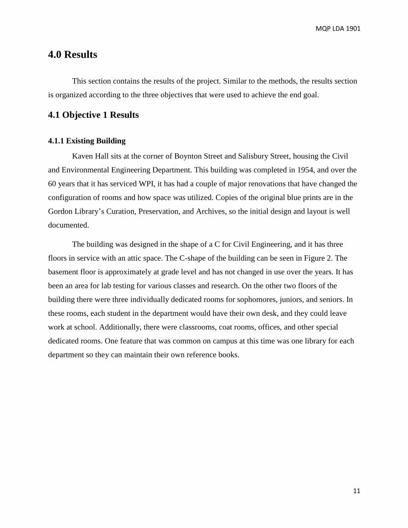
The building was designed in the shape of a C for Civil Engineering, and it has three
floors in service with an attic space. The C-shape of the building can be seen in Figure 2. The
basement floor is approximately at grade level and has not changed in use over the years. It has
been an area for lab testing for various classes and research. On the other two floors of the
building there were three individually dedicated rooms for sophomores, juniors, and seniors. In
these rooms, each student in the department would have their own desk, and they could leave
work at school. Additionally, there were classrooms, coat rooms, offices, and other special
dedicated rooms. One feature that was common on campus at this time was one library for each
department so they can maintain their own reference books.
MQP LDA 1901
12
Figure 2: Existing Kaven Hall via Google Earth
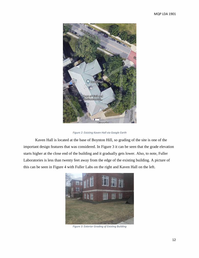
Kaven Hall is located at the base of Boynton Hill, so grading of the site is one of the
important design features that was considered. In Figure 3 it can be seen that the grade elevation
starts higher at the close end of the building and it gradually gets lower. Also, to note, Fuller
Laboratories is less than twenty feet away from the edge of the existing building. A picture of
this can be seen in Figure 4 with Fuller Labs on the right and Kaven Hall on the left.
Figure 3: Exterior Grading of Existing Building

MQP LDA 1901
13
Figure 4: Fuller labs and Kaven Hall
The grade elevations around the building were surveyed using the known bench mark on
the right side of the main stair case. This bench mark can be seen in Figure 5. This bench mark
has been assigned an elevation of 506.35’. All the elevations around the building are referenced
to this bench mark. A list of these elevations can be seen in Table 2 with their corresponding
locations seen in Figure 6.
Figure 5: Bench Mark on Stairs

MQP LDA 1901
14
Table 2: List of Survey Points and Elevations
Point Elevation Point Elevation
BM1 506.35 P.6 499.896
P.1 504.63 P.7 499.635
P.2 506.75 P.8 514.157
P.3 505.375 P.9 514.455
P.4 504.43 P.10 503.97
P.5 502.465 P.11 500.801
4.1.2 Criteria for New Design When designing a new building there are many different constraints, parameters, and
necessities that need to be considered.
4.1.2.1 Site constraints
The Worcester zoning ordinance was evaluated, and Table 3 shows the hard restraints
that needed to be enforced in the new design (Unites States, 1991). These restraints dictated
where the building had to be in reference to the lot.
Figure 6: Surveying Point Locations

MQP LDA 1901
15
Table 3: Zoning Requirements
Another constraint to consider is the slower demolition and construction time because of
the extra precautions that are necessary for protecting Fuller Labs. It also means that the new
building must align with the base of Fuller Labs to make the walkways between the buildings
efficient. Two other significant design parameters that are a result of the existing configuration
are the required setbacks and the loading dock on the west side of the existing building.
When designing this building, the locations of the utilities are also a major constraint.
WPI heats most of its buildings through steam pipes. Kaven Hall is one building that receives
these steam pipes underground, which run perpendicular to the building, and are centrally
located. This is not a utility that would be easily relocated, so when designing the new building, a
mechanical room must be positioned in the correct location. Other utilities considered are water,
sewer, and electrical. The gas and the water service locations are known and can be seen in
Figure 7.
Figure 7: Gas and Water Service Locations

MQP LDA 1901
16
4.1.2.2 Recommended Spaces and Functional Areas
An interview was conducted with the academic scheduler, Cathy Battelle. This interview
along with personal experiences and the student/ faculty surveys provided the information
necessary to derive the occupancy and types of academic spaces needed. The student faculty
survey provided over 100 thoughtful responses to help develop this list. With this information a
list was developed of necessities based on community feedback. Below is the list of necessities
in no particular order:
• 20 faculty offices
• 70-student class rooms
• 50-student computer labs
• Testing laboratories
• Tech suites
• Multiple 25-student classrooms
• Bathrooms
• Janitor closets
• Student lounge
• Elevator
• Loading dock platform
• Storage closets
• Conference rooms
• Mechanical rooms
In order to evaluate the layouts created, this list was transformed into categories. These
categories combined to create an architectural program for choosing the final layout.
4.1.2.3 Occupancy and Egress
The building code has many rules about spaces and egress. These restrictions are all
based upon occupancy. After sizing the rooms based on the recommended functional spaces and
desired capacities, the occupant load for fire safety and egress was calculated by dividing the
gross area of each space by 20, allocating each occupant at least 20 square feet of space for
usage. (IBC 2015) In Table 4, the occupant load per floor is presented with an approximate total
occupant load of 1200 people. In Table 5, minimum areas are presented for classrooms and
office space. This was used to design the floorplan layouts.

MQP LDA 1901
17
Table 4: Occupancy
Table 5: Minimum Area Criteria (IBC 2015)
These occupancy calculations defined the dimensions for many areas throughout the
building, such as the stairways, hallways, and exits. Using the building code to find the design
ratios, each design incorporated the appropriate amount of space for egress based upon the
criteria in Table 6.
Table 6: Egress Requirements
Area Max
Occupancy
Ratio Code Reference Min
Stairs 310 .2”/Occupant IBC 2015 5.16’
Hallways 310 .2”/Occupant IBC 2015 5.16’
Exits 1200 1 Exit/500
Occupants
IBC 2015 4 Exits
4.1.3 Alternative Layouts Three different designs were produced incorporating as many of the necessities within the
defined restrictions. One design reworked the classic “C” shape layout, while the other two
explored new possibilities. Each design incorporates an elevator, a mezzanine level connected to
the loading dock, and at least two 70-person classrooms.
4.1.3.1 T-Shape
The first alternative layout is a T-shape in plan. This building includes four total floors of
combined academic class rooms and collaborative space for students to do work, with all the
parameters and recommended assets accounted for. Some of the major additions were the three
Floor Gross area (sqft) Occupancy
Basement 6,200 310
1st 6,200 310
2nd 5,100 255
3rd 5,960 298
Approximate Total 24,000 1200

MQP LDA 1901
18
rooms that were put on the third floor. These rooms are a senior room, grad lounge, and a study
hall. These three rooms work as an area for the students to come and go, with tables and a few
computers to work on projects. With the proposed increases to 4 total floors and to the building
footprint, two elevators were installed, one on the north end of the building and the other one on
the south end, allowing for easy flow throughout the building.
4.1.3.2 C-Shape
The second design is essentially the same shape as the current Kaven Hall in order to
consider the option of preserving the iconic “C” shape building. There are major changes to the
spaces and, of course, the addition of the third floor. The overall arrangement in the basement is
similar. The major change is the new mezzanine level in the Northeast corner of the building.
This mezzanine is flush to the loading dock outside and access is only permitted to faculty and
staff. In this design the first floor has two large classrooms. New additions also include tech
suites and much larger spaces for the TA office, the student lounge, and faculty lounge. Both
lecture halls have two exits in case of an emergency, and the elevator is strategically located next
to the Fuller entrance.
The second floor is now home to all of the faculty offices. Students no longer have to
search the corners of the building for their professor's office as they are all conveniently located
on one floor. This floor also hosts two computer labs and two classrooms. Located in the
Northwest corner is the graduate TA office as well as another tech suite. This floor also has a
student lounge area that overlooks the Kaven courtyard.
The third floor has a much larger architectural studio than what is available now in KH
207. There are also storage units available to the different programs that are based in the Civil
and Environmental Engineering Department.
All the documents in the current attic can now be stored in the new civil engineering
archive. Also, on the fourth floor is a building code and civil reference library. To finish off the
building the floor has a café and a practice room for the ASCE student competition teams. This
design maximizes space while keeping the historical “C” shape layout.
MQP LDA 1901
19
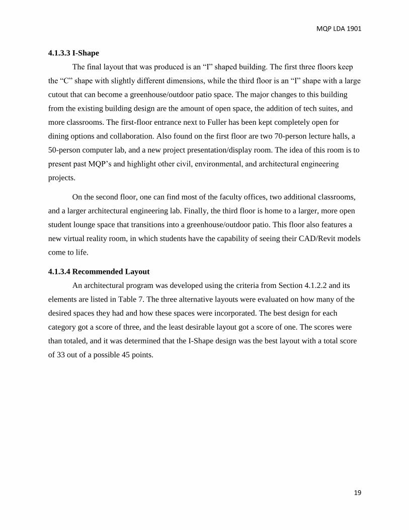
4.1.3.3 I-Shape
The final layout that was produced is an “I” shaped building. The first three floors keep
the “C” shape with slightly different dimensions, while the third floor is an “I” shape with a large
cutout that can become a greenhouse/outdoor patio space. The major changes to this building
from the existing building design are the amount of open space, the addition of tech suites, and
more classrooms. The first-floor entrance next to Fuller has been kept completely open for
dining options and collaboration. Also found on the first floor are two 70-person lecture halls, a
50-person computer lab, and a new project presentation/display room. The idea of this room is to
present past MQP’s and highlight other civil, environmental, and architectural engineering
projects.
On the second floor, one can find most of the faculty offices, two additional classrooms,
and a larger architectural engineering lab. Finally, the third floor is home to a larger, more open
student lounge space that transitions into a greenhouse/outdoor patio. This floor also features a
new virtual reality room, in which students have the capability of seeing their CAD/Revit models
come to life.
4.1.3.4 Recommended Layout
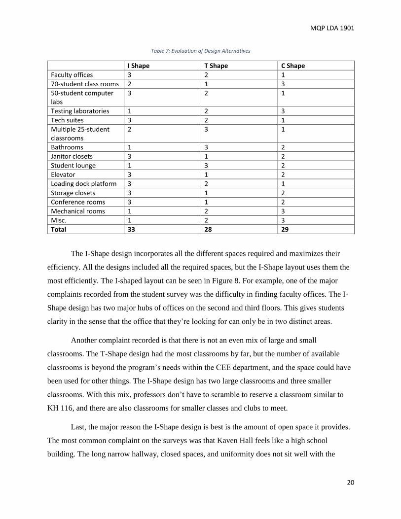
An architectural program was developed using the criteria from Section 4.1.2.2 and its
elements are listed in Table 7. The three alternative layouts were evaluated on how many of the
desired spaces they had and how these spaces were incorporated. The best design for each
category got a score of three, and the least desirable layout got a score of one. The scores were
than totaled, and it was determined that the I-Shape design was the best layout with a total score
of 33 out of a possible 45 points.
MQP LDA 1901
20
Table 7: Evaluation of Design Alternatives
I Shape T Shape C Shape
Faculty offices 3 2 1
70-student class rooms 2 1 3
50-student computer labs
3 2 1
Testing laboratories 1 2 3
Tech suites 3 2 1
Multiple 25-student classrooms
2 3 1
Bathrooms 1 3 2
Janitor closets 3 1 2
Student lounge 1 3 2
Elevator 3 1 2
Loading dock platform 3 2 1
Storage closets 3 1 2
Conference rooms 3 1 2
Mechanical rooms 1 2 3
Misc. 1 2 3
Total 33 28 29
The I-Shape design incorporates all the different spaces required and maximizes their
efficiency. All the designs included all the required spaces, but the I-Shape layout uses them the
most efficiently. The I-shaped layout can be seen in Figure 8. For example, one of the major
complaints recorded from the student survey was the difficulty in finding faculty offices. The I-
Shape design has two major hubs of offices on the second and third floors. This gives students
clarity in the sense that the office that they’re looking for can only be in two distinct areas.
Another complaint recorded is that there is not an even mix of large and small
classrooms. The T-Shape design had the most classrooms by far, but the number of available
classrooms is beyond the program’s needs within the CEE department, and the space could have
been used for other things. The I-Shape design has two large classrooms and three smaller
classrooms. With this mix, professors don’t have to scramble to reserve a classroom similar to
KH 116, and there are also classrooms for smaller classes and clubs to meet.
Last, the major reason the I-Shape design is best is the amount of open space it provides.
The most common complaint on the surveys was that Kaven Hall feels like a high school
building. The long narrow hallway, closed spaces, and uniformity does not sit well with the

MQP LDA 1901
21
student body. The I-Shape design uses unique spaces and open concepts such as the new student
lounge to turn Kaven Hall into a modern and sheik learning space.
Basement First Floor
Second Floor Third Floor
Figure 8: Final Layout

MQP LDA 1901
22
4.2 Objective 2 Results To determine the best structural frame for the proposed building both a reinforced
concrete frame and a structural steel frame were designed for gravity loads and lateral loads.
Both materials have advantages when compared to one another. These advantages entail cost,
strength, fire-resistance, and sustainability. In this section, the loads and the design of both
structures are evaluated.
4.2.1 Design Loads and Load Combinations
Design loads for both structural frames were determined in compliance of ASCE 7-10.
The load combinations, 1.4D and 1.2D +1.6L + 0.5S, were used to design for gravity loads. Load
values can be seen in the Table 8.
Table 8: Applicable Gravity Loads
Type Value
Dead Load Variable
Service Live Load First Floor 100 PSF, Other Floors 80 PSF, Roof 20 PSF
Snow Load for Flat Roof Deck & Roof 38.115 PSF
Drift Snow Load Deck 80.37 PSF
Wind Load Gradient from 19.8-16 PSF from top to bottom
4.2.2 Structural Steel Design
For the steel design, a beam system with a 5.5-inch slab (3-inch concrete slab on 2.5-inch
metal decking) was utilized for composite construction. Composite construction was used
because it allows for larger spans between columns and generally lighter beams compared to
traditional beam construction. This system allowed for an almost uniform design on all floors
besides the additional support located on the third floor under the outside rooftop patio of the
building. The patio section requires larger beam sizes to support the additional snow drift load.
When designing specific beams some deflection issues arose. This was due to the
architectural layout having large amounts of open space. To counteract this issue, larger beam
sizes were selected, and the idea of cambering during the fabrication process was also used.
Cambering beams compensates for the deflection issue because it allows for smaller beams to
settle once placed and offsets the impact of heavy loads. However, after analyzing all the beams
for deflection and span length, it was noticed, in the calculations that only a specific beam size

MQP LDA 1901
23
can be cambered at five separated locations throughout the layout. This is because when looking
back at the calculations the beam sizes were governed by moment capacity instead of deflection.
The common beam sizes used on each floor can be seen in Table 9.
The steel column grid utilizes a column at each outside vertex plus a few more along the
widths and under where the outside roof top patio is located. The location of these columns can
be seen in Figure 9. Columns were selected to be W14 x 99 at all locations to ease the fabrication
and erection process even though some could have been smaller due to smaller gravity loads.
Table 9: Structural Steel Building Components
Component Size
Slab on Grade 5-inch depth
Composite Floor Slabs 3-inch concrete slab
2.5-inch metal decking
Columns W14x99
1st Floor Beams W16x40
W18x55
W21x55
W21x57
W21x101
W24x68
W24x84
W24x117
W27x102
2nd Floor Beams W16x40
W18x55
W18x71
W21x55
W21x101
W24x68
W24x84
W27x102
3rd Floor Beams W16x40
W18x71
W21x55
W21x101
W24x68
W24x84
W24x117
W27x102
Roof Beams W16x40
W18x71
W21x55
W21x101
W24x84
W24x117
W27x102
Composite Roof Slab 3-inch concrete slab
2.5-inch metal decking

MQP LDA 1901
24
Figure 9: Steel Column and Beam Layout
4.2.3 Reinforced Concrete Design
The structural design of a reinforced concrete alternative for the new Kaven Hall building
began with adjusting the layout. The I-Shape layout selected had a surplus of open space
throughout the building. The original column grid being implemented in the steel design would
not work in the concrete design because of the large spans between columns. The new concrete
column grid is seen in layout uses 51 columns opposed to the steel grid which has 19 columns.
Although there are more columns than the structural steel option, the design takes advantage of

MQP LDA 1901
25
smaller columns, beams, and slab sizes. A full list of columns, beams, and slabs can be seen in
Table 10 and the corresponding locations can be seen in the column grid in Figure 10. Figure 11
shows the layout of beams and T-beams for the floor while in Figure 11 the typical cross section
of a T-beam is shown.
The T-beams run along the length of the building and make up the slab. The T-beam
floor system reduces the number of beams needed because they act as the beam in the direction
that they are constructed. The tops of the T-beams are also part of the slab and the supporting
beams are flush. All columns were designed based on required strength needed to support
factored design loads, including the weight of the floor system and beams. The slenderness ratio
imposed minimum dimensions on the columns. Although the minimum column dimensions may
be considered counterproductive towards the more columns, smaller size philosophy, the trade-
off was to avoid consideration of column slenderness concerns to reduce design time. The
column grid was designed to be as repeatable as possible for ease of construction. Specifying
consistent sizes for the continuous beams and columns provides formwork economy for
constructing the floor. The formwork for this process is universal and can be reused throughout
the construction process, which will save time and money.
Table 10: Concrete building components
Component Location Size(in) Steel Area (in^2)
Basement Column B-(1-9), E-(1-9) 16x16 5 - #3
Basement Column A,C,D,F-(1-9) 16x16 4 - #3
1st Floor Column B-(1-9), E-(1-9) 16x16 4 - #3
1st Floor Column A,C,D,F-(1-9) 16x16 3 - #3
2nd Floor Column A,B,C,D,E,F-(1-9) 16x16 3 - #3
3rd Floor Column A,B,C,D,E,F-(1-9) 16x16 3 - #3
Beam A EF-(1-9) and AB-(1-9) 18x12 3 - #10
Beam B BC,CD,DE-(1-9) 14x8 2 - #9
Slab on Grade Basement 5 N/A
General Floor First floor to third floor 24x18 T beam 6 - #10

MQP LDA 1901
26
Figure 10: Concrete column layout

MQP LDA 1901
27
Figure 11: Concrete Beam Layout
Figure 12: T-beam Cross Section

MQP LDA 1901
28
4.2.4 Design for Lateral Loads
Lateral loads were addressed in both the structural steel and reinforced concrete designs
to add additional support. Design parameters for lateral loads can be seen in Table 11 below. In
the steel design, an X bracing system was used on each floor to control deflection from the wind
loading since that is the governing load combination. This is because of the little to no seismic
activity in the New England area. Bracing was set up to use light weight members in tension that
did not require supporting any load in compression. This made solving for the size of these
members straight forward because it made the system determinate. When sizing members, the
radius of gyration was the governing component in this design which was determined by using
L/r <300, as prescribed by chapter D 1 “slenderness limits” (Specifications, 2016). A table can
be seen below showing the size of members used and their spans.
Table 11: Lateral Load Design Parameters
Basic Parameters
Risk Category III
Basic Wind Speed, V 100 mph
Wind Directionality Factor, Kd 0.85
Exposure Category B
Topographic Factor, Kzt 1.00
Gust Wind Factor, G 0.836
Enclosure Classification Enclosed
Internal Pressure Coefficient, GCpi +/- 0.18
Terrain Exposure Constant, α 7.0
Terrain Exposure Constant, zg 1,200 ft
Table 12: Lateral Bracing for Steel Construction
Member Size Span (feet)
WT4 x 17.5 43
WT2.5 x 8 28

MQP LDA 1901
29
In the reinforced concrete design option, shear walls were used to resist wind loads.
Minimum design requirements from the American Concrete Institute (ACI) governed the design
of this wall. The wall design was governed in three ways: the minimum wall thickness had to be
greater than 7.5 inches, the wall had to be greater than 1/25 times the unsupported distance which
is roughly 10” thick, and the minimum amount of rebar required for a wall is .002, which is used
to limit cracking from shrinkage and temperature. The resulting wall that is used in 6 locations in
the building is 56’ tall x 20’ wide x 10” thick.
4.2.5 Slab on Grade and Foundation Design
The design for both buildings contains a spread footing under every column with a frost
wall around the border of the building. A 5-inch slab-on-grade was defined for the basement
floor. This design was based on guidelines given by the Portland Cement Association (Packard,
1976) which uses the compressive strength of concrete of 4 ksi, the flexural strength of 569 psi,
and the subgrade factor K of 100 pci. These three values were then used to compute a slab
thickness of 5 inches with 760 psf allowable load (Packard, 1976). Copies of original blueprints
were reviewed in the Gordon Library’s Curation, Preservation, and Archives. Foundation notes
stated the soil bearing capacity was 3 tons psf, which was used in calculating the size of the
footings. The frost wall is used as a retaining wall to hold back the exterior grading and will give
a border for the slab on grade.

MQP LDA 1901
30
4.3 Objective 3 Results
4.3.1 Cost Estimate The cost estimate for both the structural steel and reinforced concrete construction was
completed using Revit’s material takeoff feature, Microsoft Excel, and the 2019 Building
Construction Costs with RSMeans data textbook (Mewis, 2019). Using the Uniformat
classification to organize the cost estimation, the costs per square foot of the substructure, shell,
interiors, services, equipment and furnishings, special construction, and building site work for
both concrete and steel were calculated (Charette, 2019).
Figure 13: Typical Footing for Structural Steel Frame
Figure 14: Typical Footing for Structural Concrete Frame

MQP LDA 1901
31
For both the reinforced concrete and structural steel designs, many of the sections of cost
estimation including: demolition costs, site work, equipment and furnishings, and interior work
were all the same. On the other hand, framing, floor and roof construction, foundation design,
and several utility services separated the cost between the steel and concrete options. These key
differences can be seen in Table 13.
Table 13: Cost Estimate Overview
Steel Concrete
Cost/sq ft Total Cost Cost/sq ft Total Cost
Framing $12.35 $612,600 $26.12 $1,295,600
Floor/Roof
Construction
$7.59 $180,400 $16.41 $813,900
Utilities $35.90 $1,780,600 $39.50 $1,958,700
Foundation
Design
$1.61 $79,900 $0.85 $42,200
Total Cost of
Building
$189.40 $7,850,200 $214.82 $9,307,000
The driving influence behind the cost differences in the structural steel versus concrete frame
was the ability of the steel framing to span longer distances. This allowed for fewer columns,
simple concrete flooring with metal decking instead of the T-beam design used for the concrete
frame, and easier access for utilities. The full cost estimation can be seen in Appendix K.
4.3.2 Schedule
The schedule for the steel construction framing plan was created using Primavera. The
activity list includes 64 unique activities ranging from preparing the site through building
commissioning and WPI moving into the completed facility. The tasks were arranged in the
order needed to be completed. Some tasks were able to be completed simultaneously, but other
tasks need to be completed before certain tasks can begin. For example, the construction crew
cannot place the third-floor slab until the third-floor steel framing and metal decking has been
erected. Alternatively, once the frame of the building is completed large amounts of utility work
can be done at the same time. These trends are identified in the schedule by long lines of single
tasks and big blocks of multiple tasks.
The completed schedule will take approximately one year and nine months. This entails
from the first day of site prep to the last day of WPI moving back into the building. The start date

MQP LDA 1901
32
was selected to be the first day of WPI’s spring break, March 1st, 2018. This start date implies
that all of the contents in Kaven Hall have already been removed, most likely over the winter
break. This project will end on December 30th, 2020. All of the project milestones are shown in
Figure 12. This takes advantage of WPI’s term breaks and summers resulting in the least amount
of displacement of faculty as possible.
Figure 12: Project Milestones

MQP LDA 1901
33
5.0 Conclusions and Recommendations
All in all, the goals of the project were met and a design for Kaven Hall was developed.
The gravity and lateral loads were calculated and used to size the structural components for the
frames. The structural models for both steel and concrete were put into Revit to create a 3D
model of the structure. The structural model for steel is seen below in Figure 13 and the model
for concrete is seen in Figure 14. Using these models, the amount of material was calculated and
used in the cost estimate, which was then compared to decide the best option. The tasks needed
to complete the most cost-effective building were compiled into a schedule to construct the new
building. The recommended method of construction for the new structural frame is structural
steel. Steel allows larger spaces because it can span larger distances, thus accommodating the
new layout. The steel had a much lower cost than the concrete option, partly because there were
much less columns and footings.
Figure 13: Steel Frame Structural Model

MQP LDA 1901
34
Figure 14: Concrete Frame Structural Model
At the completion of this project the team feels with more time many aspects of this
project could be further analyzed. The structural system was designed neglecting the design of
the angles, welds, or bolts for each individual connection. Also, for the concrete option the
reinforcement developmental length and bends going into abutting members was neglected. This
would need to be designed for both structures to further complete the design. Another aspect of
the project that could be further investigated is the elevator shaft and footing designs. While the
footings were designed to resist the loads of the buildings additional or larger footings may be
required depending on the size of the elevator. The design now reflects the location of the shaft
along with members sized appropriately for an opening.
Another area that could be altered for a more efficient design would be the floor plan
layout. Specifically, for the concrete design, integrating the column layout was difficult because
of the restricted span lengths of the T-beams. Also, looking into different roof options to top the
building could reduce water run-off or electricity costs. Thoughts of a green roof or solar panel
roof were discussed based on those features, but the idea was not pursued.
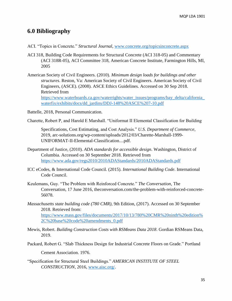
MQP LDA 1901
35
6.0 Bibliography
ACI. “Topics in Concrete.” Structural Journal, www.concrete.org/topicsinconcrete.aspx
ACI 318, Building Code Requirements for Structural Concrete (ACI 318-05) and Commentary
(ACI 318R-05), ACI Committee 318, American Concrete Institute, Farmington Hills, MI,
2005
American Society of Civil Engineers. (2010). Minimum design loads for buildings and other
structures. Reston, Va: American Society of Civil Engineers. American Society of Civil
Engineers, (ASCE). (2008). ASCE Ethics Guidelines. Accessed on 30 Sep 2018.
Retrieved from
https://www.waterboards.ca.gov/waterrights/water_issues/programs/bay_delta/california_
waterfix/exhibits/docs/dd_jardins/DDJ-148%20ASCE%207-10.pdf
Battelle, 2018, Personal Communication.
Charette, Robert P, and Harold E Marshall. “Uniformat II Elemental Classification for Building
Specifications, Cost Estimating, and Cost Analysis.” U.S. Department of Commerce,
2019, arc-solutions.org/wp-content/uploads/2012/03/Charette-Marshall-1999-
UNIFORMAT-II-Elemental-Classification....pdf.
Department of Justice, (2010). ADA standards for accessible design. Washington, District of
Columbia. Accessed on 30 September 2018. Retrieved from
https://www.ada.gov/regs2010/2010ADAStandards/2010ADAStandards.pdf
ICC eCodes, & International Code Council. (2015). International Building Code. International
Code Council.
Keulemans, Guy. “The Problem with Reinforced Concrete.” The Conversation, The
Conversation, 17 June 2016, theconversation.com/the-problem-with-reinforced-concrete-
56078.
Massachusetts state building code (780 CMR), 9th Edition, (2017). Accessed on 30 September
2018. Retrieved from:
https://www.mass.gov/files/documents/2017/10/13/780%20CMR%20ninth%20edition%
2C%20base%20code%20amendments_0.pdf
Mewis, Robert. Building Construction Costs with RSMeans Data 2018. Gordian RSMeans Data,
2019.
Packard, Robert G. “Slab Thickness Design for Industrial Concrete Floors on Grade.” Portland
Cement Association. 1976.
“Specification for Structural Steel Buildings.” AMERICAN INSTITUTE OF STEEL
CONSTRUCTION, 2016, www.aisc.org/.

MQP LDA 1901
36
United States, Congress, City Hall. “City of Worcester Zoning Board of Appeal .” City of
Worcester Zoning Board of Appeal , City of Worcester , 1991, pp. 1–27.
United States Department of Labor. “UNITED STATES DEPARTMENT OF LABOR.”
Occupational Safety and Health Administration. Accessed on 30 September 2018.
Retrieved from: www.osha.gov/oshstats/commonstats.html

MQP LDA 1901
37
Appendix A: Project Proposal
WPI Replacement to Kaven Hall:
Structural Design
Major Qualifying Project Proposal
Presented by:
Laurence Cafaro, Nicholas Day, James Loring, & Eric Schroeder
Presented to:
Professor Leonard Albano and the Worcester Polytechnic Institute Civil
Engineering Department
2018-2019
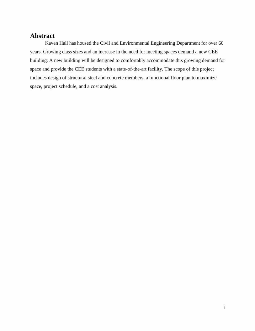
i
Abstract Kaven Hall has housed the Civil and Environmental Engineering Department for over 60
years. Growing class sizes and an increase in the need for meeting spaces demand a new CEE
building. A new building will be designed to comfortably accommodate this growing demand for
space and provide the CEE students with a state-of-the-art facility. The scope of this project
includes design of structural steel and concrete members, a functional floor plan to maximize
space, project schedule, and a cost analysis.
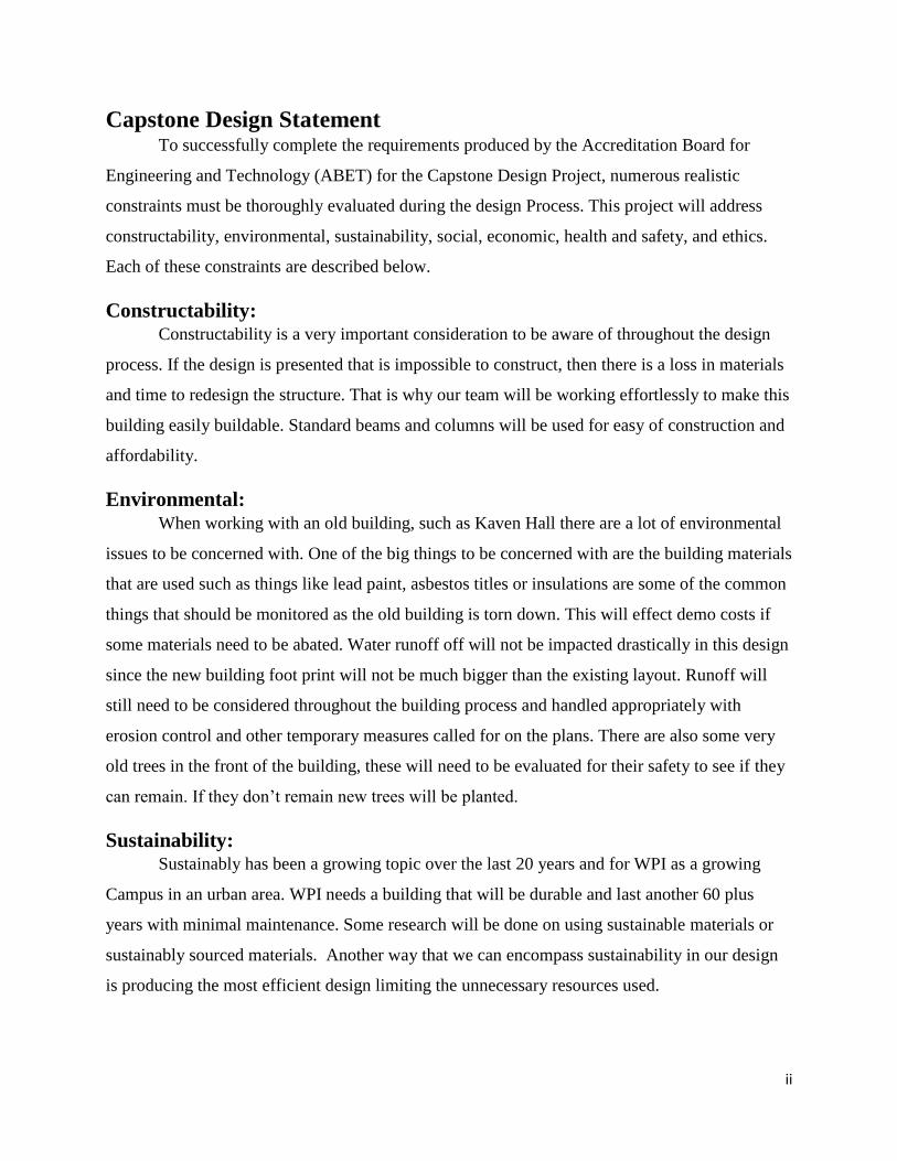
ii
Capstone Design Statement To successfully complete the requirements produced by the Accreditation Board for
Engineering and Technology (ABET) for the Capstone Design Project, numerous realistic
constraints must be thoroughly evaluated during the design Process. This project will address
constructability, environmental, sustainability, social, economic, health and safety, and ethics.
Each of these constraints are described below.
Constructability: Constructability is a very important consideration to be aware of throughout the design
process. If the design is presented that is impossible to construct, then there is a loss in materials
and time to redesign the structure. That is why our team will be working effortlessly to make this
building easily buildable. Standard beams and columns will be used for easy of construction and
affordability.
Environmental: When working with an old building, such as Kaven Hall there are a lot of environmental
issues to be concerned with. One of the big things to be concerned with are the building materials
that are used such as things like lead paint, asbestos titles or insulations are some of the common
things that should be monitored as the old building is torn down. This will effect demo costs if
some materials need to be abated. Water runoff off will not be impacted drastically in this design
since the new building foot print will not be much bigger than the existing layout. Runoff will
still need to be considered throughout the building process and handled appropriately with
erosion control and other temporary measures called for on the plans. There are also some very
old trees in the front of the building, these will need to be evaluated for their safety to see if they
can remain. If they don’t remain new trees will be planted.
Sustainability: Sustainably has been a growing topic over the last 20 years and for WPI as a growing
Campus in an urban area. WPI needs a building that will be durable and last another 60 plus
years with minimal maintenance. Some research will be done on using sustainable materials or
sustainably sourced materials. Another way that we can encompass sustainability in our design
is producing the most efficient design limiting the unnecessary resources used.

iii
Social: A building on any campus must be socially accepted by its users for it to be efficiently
used. The proposed design will be more user friendly for everyone. This starts with the
professors who will have class rooms that adequately meet their needs. The building will be
more accessible for all students with ADA Compliant rooms and this significant addition of an
elevator. The facilities staff will enjoy working in this building as it will be tied into the loading
dock already present at the base of Fuller Labs with easy access to the elevator to facilitate the
distribution of paper goods and cleaning product and for easy removal of trash and recyclables.
Economic: Economic analysis of the proposed building will focus mainly the structural components
and there will be an estimated allowance for other elements of the building to understand the
total cost of the project. Cost is an important consideration since it will be funded by WPI, and
the board of trustees will want the most economical design that will meet their needs. This cost
estimate will be compared to other construction options that WPI has evaluated for Kaven Hall.
Health and Safety: Health and safety need to be considered for the duration of the project, especially in the
construction period. The United States Department of Labor states that in 2016 that there were
more than 14 deaths a day (United, 2018). Accident rates can be reduced by having more
systems pre-fabricated by contractors at their warehouse. Long term safety factors that will be
evaluated will be snow load, occupancy load and fire restrictions to name a few. To do this we
will be using the Massachusetts Building Code (780 CMR), International Building Code (IBC
2015), and The American Society of Civil Engineers Standards (ASCE-10) to make sure we
meet all safety requirements.
Ethics: When it comes to ethics, proper decisions must always be made based on building codes,
OSHA regulations, and morality. This will ensure that Kaven Hall is designed and built ethically
and complies with all the required provisions. Understanding the appropriate licensure
requirements for structural design will give us, the design team, insight and moral/ethical values
when it comes to executing this project. Provisions and regulations must always be followed and
should never be abused, even if there may be any potential loopholes. Building quality and the

iv
safety of the occupants are the most important concerns when it comes to designing and
constructing a new building.
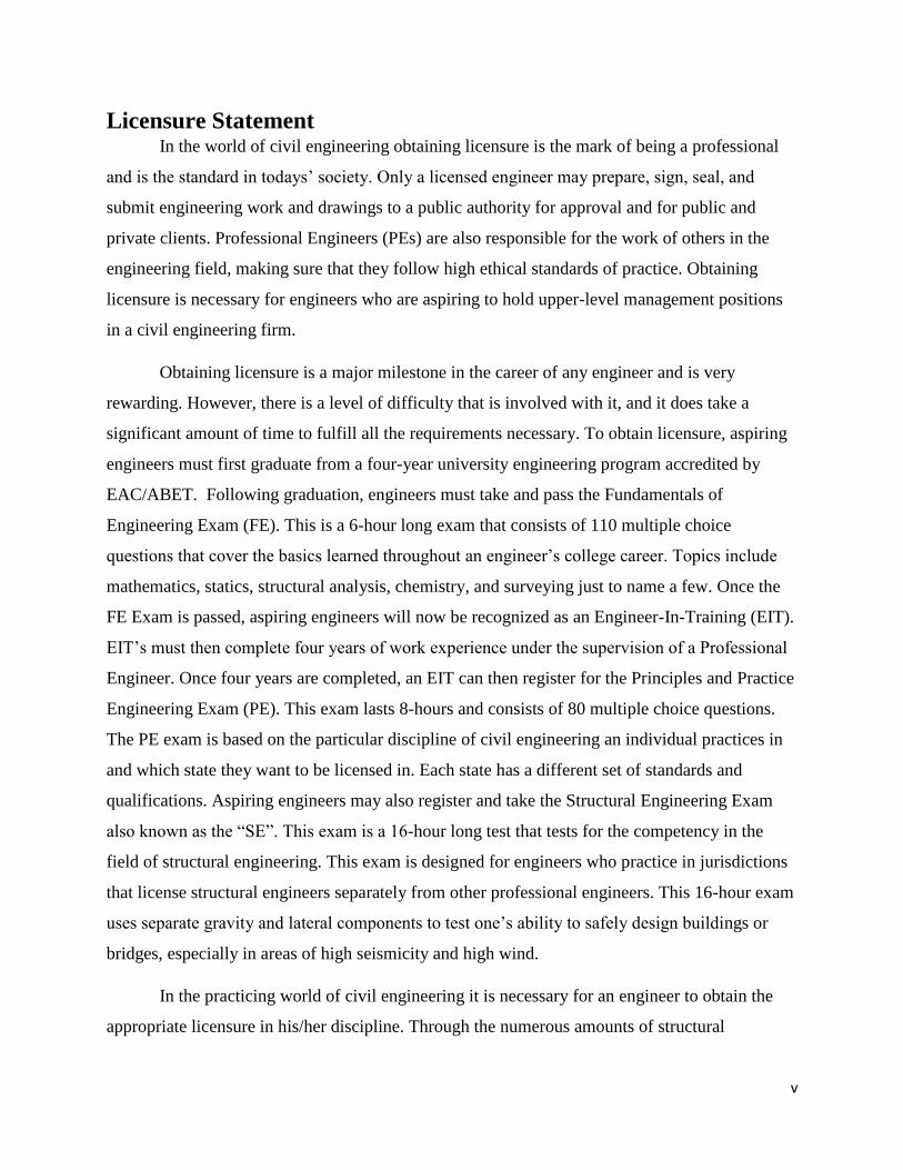
v
Licensure Statement In the world of civil engineering obtaining licensure is the mark of being a professional
and is the standard in todays’ society. Only a licensed engineer may prepare, sign, seal, and
submit engineering work and drawings to a public authority for approval and for public and
private clients. Professional Engineers (PEs) are also responsible for the work of others in the
engineering field, making sure that they follow high ethical standards of practice. Obtaining
licensure is necessary for engineers who are aspiring to hold upper-level management positions
in a civil engineering firm.
Obtaining licensure is a major milestone in the career of any engineer and is very
rewarding. However, there is a level of difficulty that is involved with it, and it does take a
significant amount of time to fulfill all the requirements necessary. To obtain licensure, aspiring
engineers must first graduate from a four-year university engineering program accredited by
EAC/ABET. Following graduation, engineers must take and pass the Fundamentals of
Engineering Exam (FE). This is a 6-hour long exam that consists of 110 multiple choice
questions that cover the basics learned throughout an engineer’s college career. Topics include
mathematics, statics, structural analysis, chemistry, and surveying just to name a few. Once the
FE Exam is passed, aspiring engineers will now be recognized as an Engineer-In-Training (EIT).
EIT’s must then complete four years of work experience under the supervision of a Professional
Engineer. Once four years are completed, an EIT can then register for the Principles and Practice
Engineering Exam (PE). This exam lasts 8-hours and consists of 80 multiple choice questions.
The PE exam is based on the particular discipline of civil engineering an individual practices in
and which state they want to be licensed in. Each state has a different set of standards and
qualifications. Aspiring engineers may also register and take the Structural Engineering Exam
also known as the “SE”. This exam is a 16-hour long test that tests for the competency in the
field of structural engineering. This exam is designed for engineers who practice in jurisdictions
that license structural engineers separately from other professional engineers. This 16-hour exam
uses separate gravity and lateral components to test one’s ability to safely design buildings or
bridges, especially in areas of high seismicity and high wind.
In the practicing world of civil engineering it is necessary for an engineer to obtain the
appropriate licensure in his/her discipline. Through the numerous amounts of structural

vi
calculations and designs a licensed engineer works to ensure the safety of those who interact and
occupy a building or structure.

vii
Table of Contents
Abstract .................................................................................................................................................. i
Capstone Design Statement ................................................................................................................... ii
Constructability: ................................................................................................................................ ii
Environmental: .................................................................................................................................. ii
Sustainability: .................................................................................................................................... ii
Social: ................................................................................................................................................. ii
Economic: ......................................................................................................................................... iii
Health and Safety: ............................................................................................................................ iii
Ethics: ............................................................................................................................................... iii
Licensure Statement ............................................................................................................................. iv
Table of Figures:................................................................................................................................... ix
Table of Tables: .................................................................................................................................... ix
1.0 Introduction ..................................................................................................................................... 1
2.0 Background ...................................................................................................................................... 2
2.1 Construction Materials ................................................................................................................ 2
2.1.1 Concrete ................................................................................................................................ 2
2.1.2 Steel ....................................................................................................................................... 3
2.2 Design Tools ................................................................................................................................. 4
2.2.1 Revit ....................................................................................................................................... 4
2.2.2 RAM Structural System ........................................................................................................ 5
2.2.3 Microsoft Excel and Tekla’s TEDDs .................................................................................... 5
2.2.4 Primavera .............................................................................................................................. 6
2.3 Design Parameters ....................................................................................................................... 6
3.0 Methodology .................................................................................................................................... 8
3.1 Objective 1: Develop an architectural program to create and compare layouts based on
community sentiment, the current condition of the building, and academic necessity. ............... 8
3.2 Objective 2: Design a building frame with steel and concrete alternatives based on gravity
and lateral loads. ............................................................................................................................ 9
3.3 Objective 3: Determine the cost effectiveness of each building frame and decide the best
option for the building. ................................................................................................................ 10
4.0 Results ............................................................................................................................................ 11
4.1 Objective 1 Results ..................................................................................................................... 11

viii
4.1.2 Criteria for New Design .......................................................................................................... 14
4.1.2.1 Site constraints ................................................................................................................. 14
4.1.2.2 Recommended Spaces and Functional Areas .................................................................. 16
4.1.2.3 Occupancy and Egress ..................................................................................................... 16
4.1.3 Alternative Layouts................................................................................................................. 17
4.1.3.1 T-Shape ............................................................................................................................. 17
4.1.3.2 C-Shape ............................................................................................................................ 18
4.1.3.3 I-Shape .............................................................................................................................. 19
4.1.3.4 Recommended Layout ...................................................................................................... 19
4.2 Objective 2 Results ........................................................................................................................ 22
4.2.1 Design Loads and Load Combinations ............................................................................... 22
4.2.2 Structural Steel Design........................................................................................................ 22
4.2.3 Reinforced Concrete Design ............................................................................................... 24
4.2.4 Design for Lateral Loads .................................................................................................... 28
4.2.5 Slab on Grade and Foundation Design ............................................................................... 29
4.3 Objective 3 Results ........................................................................................................................ 30
4.3.1 Cost Estimate ...................................................................................................................... 30
4.3.2 Schedule ............................................................................................................................... 31
5.0 Conclusions and Recommendations .............................................................................................. 33
6.0 Bibliography .................................................................................................................................. 35
Appendix A: Project Proposal ............................................................................................................ 37
Abstract .................................................................................................................................................. i
Capstone Design Statement ................................................................................................................... ii
Constructability: ................................................................................................................................ ii
Environmental: .................................................................................................................................. ii
Sustainability: .................................................................................................................................... ii
Social: ................................................................................................................................................ iii
Economic: ......................................................................................................................................... iii
Health and Safety: ............................................................................................................................ iii
Ethics: ............................................................................................................................................... iii
Licensure Statement .............................................................................................................................. v
Table of Figures:.................................................................................................................................... x
Table of Tables: ..................................................................................................................................... x

ix
1.0 Introduction ..................................................................................................................................... 1
2.0 Background ...................................................................................................................................... 2
2.1 Existing Conditions ...................................................................................................................... 2
2.2 Construction Materials ................................................................................................................ 3
2.2.1 Concrete ................................................................................................................................ 3
2.2.2 Steel ....................................................................................................................................... 4
2.3 Design Tools ................................................................................................................................. 5
2.3.1 Revit ....................................................................................................................................... 5
2.3.2 RAM Structural System ........................................................................................................ 5
2.3.3 Microsoft Excel and Tekla’s TEDDs .................................................................................... 6
2.4 Design Parameters ....................................................................................................................... 6
3.1 Existing Conditions ...................................................................................................................... 9
3.2 Floor Plan Layout ...................................................................................................................... 10
3.3 Building Design .......................................................................................................................... 10
3.4 Design Analysis .......................................................................................................................... 11
4.0 Deliverables .................................................................................................................................... 12
5.0 Bibliography .................................................................................................................................. 13
Appendix B: Alternative Layouts ....................................................................................................... 14
Appendix C: Survey Questions ........................................................................................................... 19
Appendix D: Snow Load ..................................................................................................................... 20
Appendix E: Gravity Load Steel ......................................................................................................... 21
Appendix F: Gravity Load Concrete .................................................................................................. 55
Appendix G: Lateral Load Steel ......................................................................................................... 61
Appendix H: Lateral Load Concrete .................................................................................................. 70
Appendix I: Footing Design ................................................................................................................ 73
Appendix J: Material Takeoffs ........................................................................................................... 76
Appendix K: Cost Estimate ................................................................................................................. 78
Appendix L: Schedule ......................................................................................................................... 79

x
Table of Figures: Figure 1: Kaven Hall Google Maps View ................................................................................................... 3
Figure 2: MQP Methods and Deliverables Schedule ................................................................................. 9
Table of Tables: Table 1: Design Parameters ..................................................................................................................... 7
Table 2: Methods & Deliverables Breakdown .......................................................................................... 8
Table 3: Deliverables Responsibilities .................................................................................................... 12

1
1.0 Introduction
Kaven Hall is located on the corner of Salisbury Street and Boynton Street and is home to
the Civil and Environmental Engineering Department at Worcester Polytechnic Institiute (WPI).
It was built in 1954, and named after a graduate of the 1865 class, Moses Kaven a generous
benefactor for WPI. Kaven Hall’s exterior was built out of Brick and Limestone creating a sturdy
exoskeleton. The floor plan of the building accommodates many different class sizes and faculty
offices. Over the sixty plus years that Kaven Hall has provided for the WPI community, it is
approaching time for a new facility. Kaven Hall is getting small for the growing class sizes that
WPI has, and it is also limiting to the fact it does not have an elevator.
Our project will be a complete redesign of Kaven Hall to meet building code, fit typical
class sizes at WPI, and be welcoming to the end users within the Civil and Environmental
Engineering department. The proposed building that our team will be designing over the next
two terms is a four story I-shaped building. This building will include multiple 70-student class
rooms, 25-student class rooms, tech suites, offices, testing laboratories, and computer labs. We
will be designing both steel and concrete frames to be compared for constructability, economics
and scheduling. Other aspects of our project will include the survey of existing conditions,
scheduling, cost estimates, and foundation design.
2
2.0 Background
This project is intended to provide a complete redesign of Kaven Hall by designing both
steel and concrete frames that will be compared for constructability, economics and scheduling.
The most constructible, cost effective and efficient design will then be identified and selected.
The ultimate goal of this design is to provide students and professors with the necessary
amenities and space needed to further their education and research in Civil Engineering and
beyond. By developing this new design, Kaven Hall, will finally be able to accommodate the
larger classes of sixty-plus students for the CE 2000 level classes, and be able to efficiently
perform class labs and research in the new laboratory on the bottom floor of the building. In
order to properly deliver this project, certain background knowledge and understanding is
required. This background section provides an overview of the necessary information regarding
the numerous factors that must be taken into consideration in the design of a new Kaven Hall.
Information regarding the current status of the project site, the regulatory provisions and design
parameters to deliver a safe and constructible project, and the properties of the materials used can
be found in this section.
2.1 Existing Conditions Kaven Hall sits at the corner of Boynton Street and Salisbury Street housing the Civil and
Environmental Engineering Department. This building was completed in 1954 and was a
completely Civil Engineering building and over the 60 years that it has serviced WPI it has had a
couple of major renovations which has changed the configuration of rooms and how space was
utilized. The original blue prints are in the WPI archives, so the initial design and layout is well
documented. The building was designed in the shape of a C for Civil engineering and it has three
floors in service with an attic space. The basement floor is approximately at grade level and has
not changed in use over the years: it has been an area for lab testing for various classes. On the
other two floors of the building there were three individual dedicated rooms for sophomores,
juniors, and seniors. In these rooms, each student in the department would have their own desk
and they could leave work at school, so it wouldn’t need to be transported to and from school.
Throughout the other two floors there were class rooms, coat rooms, offices, and other special
dedicated rooms. One feature that was common on campus at this time was one library for each
department so Kaven Hall had a library for civil reference books.

3
Figure 15: Kaven Hall Google Maps View
2.2 Construction Materials Over thousands of years of construction history, some of the building materials have
changed drastically, and some have stood the test of time and are still used today. When
designing a building it is crucial that the best materials are selected to make the final outcome a
resilient building that will last for the end users with as little maintenance as possible.
2.2.1 Concrete
Concrete is a composite material that is formed from a hydration reaction, which reaches
its rated strength at 28 days. Concrete normally is made with Portland cement, aggregate, water
and admixtures as needed to produce the desired material properties and quality. Concrete is
used in most cases because of its workability and versatility on a job with such a high strength
once cured.
Reinforced concrete consists of reinforcing bars, rebar for short, embedded in concrete.
The rebar is generally made of steel with nobbles or ridges that anchor firmly into the concrete,
in order to avoid slipping. There are many techniques used to reinforce concrete, but one

4
technique consists of tying rebar together with wire to form a cage, which the wet concrete is
then placed on and hardens over. The concrete and rebar combine to resist compressive, tensile,
and shear forces. The rebar is able to increase the compression capacity of the reinforced
concrete while also absorbing the majority of the tensile and shear forces.
The use of reinforcement increases compression capacity, enhances ductility, and reduces
long-term deflections of concrete elements. It also increases the flexural capacity of beams.
Another technique for reinforcing concrete uses stirrups, ties, and hoops to provide lateral
reinforcement, which resists principle stresses resulting from shear. This technique provides
confinement to column beams and joints in highly stressed areas of compression zones, which is
especially important in structures located in high seismic risk zones because it improves their
strength and ductility.
Steel is the common choice for reinforcement because it expands and contracts in the heat
and cold roughly as much as concrete. This reduces the likelihood of the steel cracking the
concrete due to varying temperatures. However, if the concrete cracks and water is able to
penetrate the reinforced concrete structure, it can rust the steel rebar. This process ruins the
durability of concrete structures, and it is difficult to detect and repair. Deterioration due to
rusting can begin in as little as 10 years and has resulted in shorter life spans of 50-100 years in
reinforced concrete structures (Keulemans).
2.2.2 Steel Steel is a very common material used for constructing high occupancy buildings since it
can carry very high compressive and tensile forces. Steel is used over other materials due to its
speed of construction with the use of bolts or welds. Smaller, easily transportable beams and
columns can come together on-site to produce a strong lightweight building frame. These beams
and columns are typical w-section style beams, which can carry high tension and compressive
forces in a lighter, more compact shape.
Steel Structures tend to have longer spans between columns than concrete structures.
Normally, buildings that have steel structures allow for more flexibility and can be divided up
with metal stud and gypsum boards more easily. When compared to concrete, steel has more
available open space due to the reduced number of columns which allows for the space to be

5
easily repurposed. Steel structures also produce generally more variability in design since they
can generally implement large overhangs and glass faced wall more easily.
One of the properties that makes steel a great structural framing component is its
ductility. With the increased ductility, steel greatly reduces the effective seismic loads that must
be accounted for compared to the effective seismic loads that a rigid concrete frame will have to
carry. This will allow for a smaller members to be chosen, reducing cost of the project and
making the self-weight of the frame lower.
2.3 Design Tools There are many engineering tools that can be utilized in the design process for a
particular structure or building. Autodesk Revit, RAM Structural System, Microsoft Excel, and
Tekla’s TEDDs are some of the software we will be using in this MQP to perform calculations,
structural analysis, and ultimately the redesign of Kaven Hall.
2.3.1 Revit
Autodesk Revit is a 3D modeling software typically used for creating structural and
architectural models of buildings or structures. The software allows a design to be created in 2D
as well as a 3D representation. This software is great for adding architectural and structural
members for a particular structure. For example, the selection of beam and column sizes can be
implemented within the software to give an actual representation of the building frame.
2.3.2 RAM Structural System
RAM Structural System is a structural analysis software provided by Bentley that allows
users to create computer models of the structural members they have designed. For example, a
steel framing system for a particular building design can be implemented in RAM. Loads and
load factors must then be applied to the structure in both the vertical and horizontal directions to
simulate the various load combinations that must be considered for design based on the specific
building codes governing local construction. Once the loads and loading combinations are
implemented, this software has the ability to size all the structural members to the most optimal,
cost-effective, and lightest structural design. The software is also capable of analyzing the effects
of the loads on the given structure by determining moment, shear, and deflection values. RAM
has made itself very convenient for structural engineers by providing printable reports for each
6
individual component of the building’s shell (ie: an exterior beam) along with the entire
structural frame.
2.3.3 Microsoft Excel and Tekla’s TEDDs
Hand-calculations can become repetitive when designing multiple components of a
building with numerous loads and loading combinations. Microsoft Excel software provides the
ability to create spreadsheets capable of performing the necessary calculations for multiple
iterations of similar member types. The software makes use of data and formulas to output the
necessary design values. The sheets can be repeated, increasing the speed and efficiency of the
design process. Microsoft Excel can be very helpful when trying to calculate the snow and wind
loading on a specific part of the building through the easy development and implementation of
the design equations in Excel.
Just like Microsoft Excel, TEDDs is another software that can be used to complete
numerous repetitive calculations and can be actually linked back to Excel. Created by Tekla,
TEDDs is a fast and easy software to learn, and is widely used in the field by structural
engineers. TEDDs has the ability to perform 2-D structural frame analysis, generate loads and
loading combinations, and determine properties for sections.
2.4 Design Parameters When it comes to designing any structure or building, safety and constructability are the
ultimate underlying responsibilities of any engineer. It is extremely important and a requirement
for a building project to comply with all national, state, and local rules and regulations to ensure
a safe design and building practice. In Massachusetts, all current and future buildings must be in
compliance with provisions of Minimum Design Loads for Buildings and Other Structures
(ASCE 7-10), the International Building Code (IBC 2015), the Americans with Disabilities Act
(ADA) and the Massachusetts State Building Code (780 CMR).

7
Table 14: Design Parameters
Provision Use
Minimum Design Loads for Buildings and
Other Structures (ASCE 7-10)
Snow Loads
Wind Loads
Seismic Loading
Floor and Roof Live Load
International Building Code (IBC 2015) General building heights and area
Foundation Inspections
General structural design
Occupancy requirements
Quality control of materials
Americans with Disabilities Act (ADA) Hall way widths
Door widths
Elevator requirements
Ramp slopes
Massachusetts State Building Code (780
CMR)
Adopts IBC and ASCE 7 by reference, as well
as provides certain provisions unique to
Massachusetts
In order to successfully redesign Kaven Hall the project has been separated into phases.
Completing these phases in a specific timeframe will keep the project on schedule and will help
to limit errors and omissions that would undermine the quality of work. Table 2 lists the phases
of the project and the tasks associated with each phase. Figure 2 illustrates the project schedule
and outlines the critical path in completing the report.

8
Table 15: Methods & Deliverables Breakdown
Phase Activity
1. Existing Conditions Site Evaluation. Faculty Interviews. Site Survey.
2. Floor Plan Layout Faculty Interviews. Locate Construction Restraints in Building
Code. Organize necessary elements within a feasible
budget.
3. Building Design Foundation Design. Concrete Frame Design. Steel Frame Design.
4. Design Analysis Compare cost of steel vs concrete design.
Compare estimated time of completion of
steel vs concrete design. Compare spaces available to information from
interview.
5. Schedule Estimate Demolition of existing building
New Construction
6. Cost Estimate Final Design

9
Figure 16: MQP Methods and Deliverables Schedule
3.1 Existing Conditions
The first phase in any design process is to evaluate the site beforehand. The building will
be analyzed for key features that need to be retained in the new design. The building performs
many different functions, thus, documenting them is important to the final design. To further
understand these functions, interviews with a variety of professors within the civil engineering
department will be held. It is imperative to the design to address concerns of those occupying
the space on a daily basis.
An interview will be conducted with the academic scheduler, Cathy Battelle. This
interview will provide us with the occupancy and types of academic spaces needed. With this
information we can develop a list of necessities for the new design.
According to the original drawings there are no records documenting the site boundaries
and elevations. To complete the site evaluation a survey will be conducted on the topography of
the site. With this being said, a series of data points will be collected around Kaven Hall to
enable an accurate foundation design.

10
3.2 Floor Plan Layout
The floor plan layout will incorporate all the ideas gathered in phase one. After all the
wants and needs have been received, the building codes need to be taken into consideration.
Parameters such as emergency exits, capacities, and ADA compliancy need to be taken into
consideration. The current building code is the International Build Code 2015, but there are also
criteria in the Massachusetts State Building Code that will be used in this design. The last part of
this process is to organize all of the elements of the design within a reasonable amount of space
and for a feasible amount of money. With the combination of the building code and the desires of
faculty, there will need to be a prioritization of elements. Multiple layouts will be proposed and
evaluated to identify the one that fits the best.
3.3 Building Design
After the floor plan layout is completed, the structural design of the new building will
begin. This design will be based off today’s building codes and will be as cost-effective as
possible; while still adhering to the wishes of the university.
3.3.1 Foundation Design
When designing a foundation of any building, a soil analysis must first be executed. For
this design of Kaven Hall, the original 1952 test results will be used. Ideally, foundations tend to
be composed of reinforced concrete and typical components will be calculated/repeated
throughout the design. Extra components will be designed only for special cases forced by the
layout. Important focuses of design in this section are:
• Typical / Special Spread Footings
• Typical / Foundation Walls
• Typical / Continuous Footings
3.3.2 Frame Design
The next step involves two structural systems for the rest of the building. The first design
will continue to utilize concrete for the building superstructure. This design will benefit from the
great compressive strength of concrete but will have to accommodate scheduling challenges due
to New England’s climate. The second design will use steel as the primary structural frame. This

11
alternative will benefit due to steel’s adaptability and faster construction rates. As for the
foundation, building components will be designed and adopted repetitively throughout most of
the frame. Important focuses of the structural design are:
• Typical / Special Beams
• Typical / Special Girders
• Typical / Special Columns
• Roof System
3.4 Design Analysis
After the designs are completed, they will be compared based on their layout capabilities,
scheduling, and cost. The estimated time to complete these designs is important because this is
an academic building. Based on the previous construction of academic buildings on campus this
project should be implemented as a design-build with a “fast-track” schedule. This will allow
WPI to plan accordingly to the time implications of the demolition and construction of the new
building. The time as mentioned before will be incorporated into the cost, which is the most
important thing for the owner. This will be evaluated on worker days and cost overhead per day.
The amount of material and time required for installation will be estimated for both designs.
Material takeoffs will be used and formulated in an Excel spreadsheet. This cost analysis will be
the leading factor for identifying which design alternative will be selected.

12
4.0 Deliverables At the completion of this project our team will provide a structural design of our
proposed Kaven Hall. Along with this will include analysis of the structural members,
foundation, project schedule, cost analysis and a model of the proposed building. Our project
will be summarized in a final report which will include our calculations, design consideration,
and constraints.
Table 16: Deliverables Responsibilities
Deliverable Primary Author(s) Assistant Author(s)
Proposal All All
Foundation James Larry
Building Structure Larry James
Cost Analysis Eric Nick
3D Model James Nick
Final Report All All
Background Larry Nick
Methodology Eric Nick
Report Editing All All
Paper Formatting Nick All
Poster Design Nick Larry

13
5.0 Bibliography
American Society of Civil Engineers. (2010). Minimum design loads for buildings and other
structures. Reston, Va: American Society of Civil Engineers. American Society of Civil
Engineers, (ASCE). (2008). ASCE Ethics Guidelines. Accessed on 30 Sep 2018.
Retrieved from
https://www.waterboards.ca.gov/waterrights/water_issues/programs/bay_delta/california_
waterfix/exhibits/docs/dd_jardins/DDJ-148%20ASCE%207-10.pdf
Battelle, 2018, Personal Communication.
Department of Justice, (2010). ADA standards for accessible design. Washington, District of
Columbia. Accessed on 30 September 2018. Retrieved from
https://www.ada.gov/regs2010/2010ADAStandards/2010ADAStandards.pdf
ICC eCodes, & International Code Council. (2015). International building code International
Code Council.
Keulemans, Guy. “The Problem with Reinforced Concrete.” The Conversation, The
Conversation, 17 June 2016, theconversation.com/the-problem-with-reinforced-concrete-
56078.
Massachusetts state building code (780 CMR), 8th Edition, (2010). Accessed on 30 September
2018. Retrieved from
https://www.architects.org/sites/default/files/780%20CMR_Chapter%201.pdf
United States Department of Labor. “UNITED STATES DEPARTMENT OF LABOR.”
Occupational Safety and Health Administration. Accessed on 30 September 2018.
Retrieved from www.osha.gov/oshstats/commonstats.html

14
Appendix B: Alternative Layouts T-Shape
Basement First Floor
Second Floor Third Floor

15
C-Shape
Basement
First Floor

16
Second Floor
Third Floor
Mezzanine

17
I-Shape
Basement First Floor
18
Second Floor Third Floor

19
Appendix C: Survey Questions
Student Survey
1. What is your major?
2. What is your year of graduation?
3. Do you think that Kaven Hall's basement lab space is conducive to work flow?
4. Are Kaven Hall's computer labs adequate in space?
5. Would you prefer large classrooms such as (KH116) or smaller classrooms such as
(KH115)?
6. Do you use the Student Lounge as a workplace?
7. Do you think the Student Lounge is a comfortable working environment?
8. Have you had a hard time finding faculty offices in Kaven Hall?
9. Do you prefer to work and meet, in public or private areas? (Lounge vs Tech Suite)
10. How likely would you visit a small cafe located in Kaven Hall?
11. What is your favorite aspect of Kaven Hall?
12. What do you dislike most about Kaven Hall?
13. What do you think is missing from Kaven Hall?
Faculty Survey
1. Do you primarily work in Kaven Hall?
2. Do you think that Kaven Hall's basement lab space is conducive to work flow?
3. Are Kaven Hall's computer labs adequate in space?
4. Would you prefer large classrooms such as (KH116) or smaller classrooms such as
(KH115)?
5. If you have an office in Kaven Hall, do you like the location relative to the spaces in the
building?
6. How likely would you visit a small cafe located in Kaven Hall?
7. What is your favorite aspect of Kaven Hall?
8. What do you dislike most about Kaven Hall?
9. What do you think is missing from Kaven Hall?
10. Any other comments?

20
Appendix D: Snow Load

21
Appendix E: Gravity Load Steel

22

23

24

25
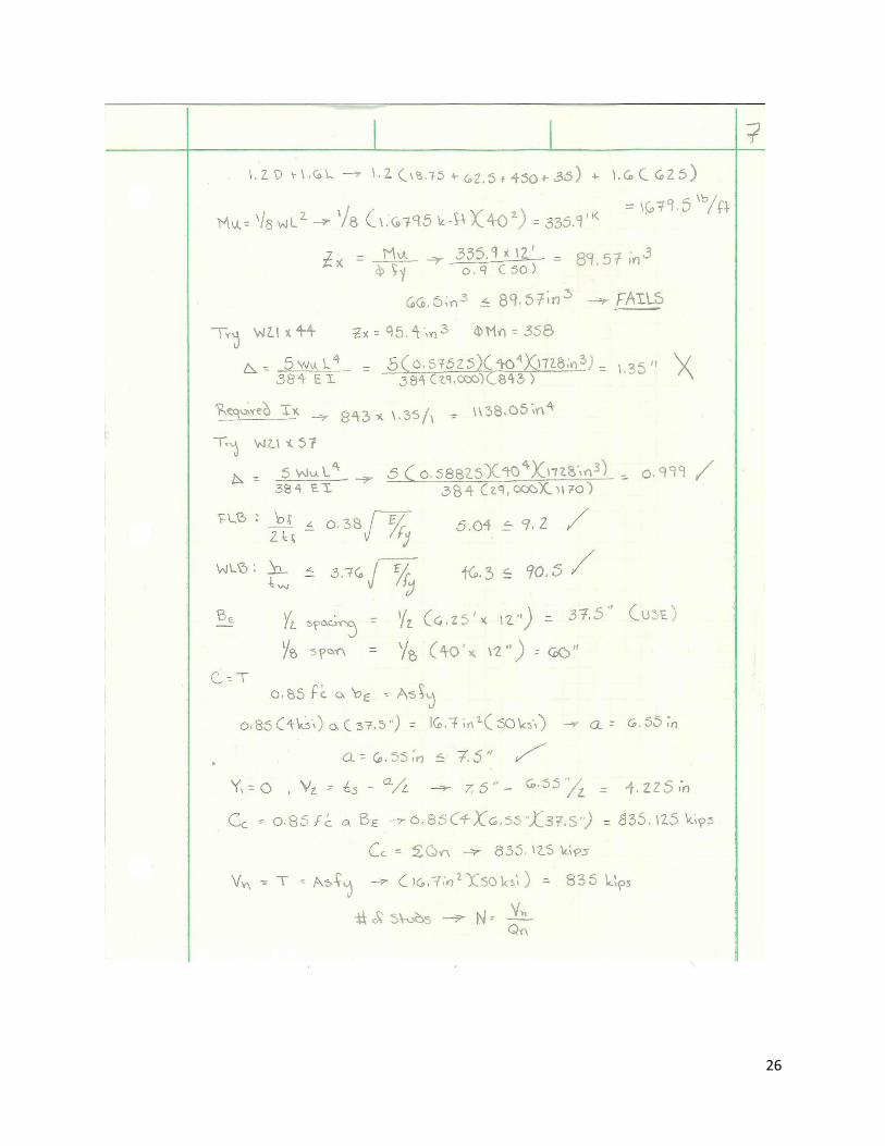
26

27

28

29

30

31

32

33

34

35

36

37
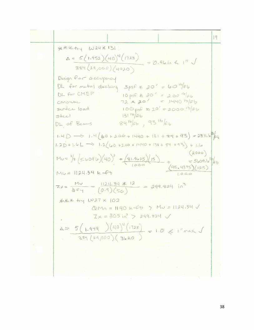
38

39

40
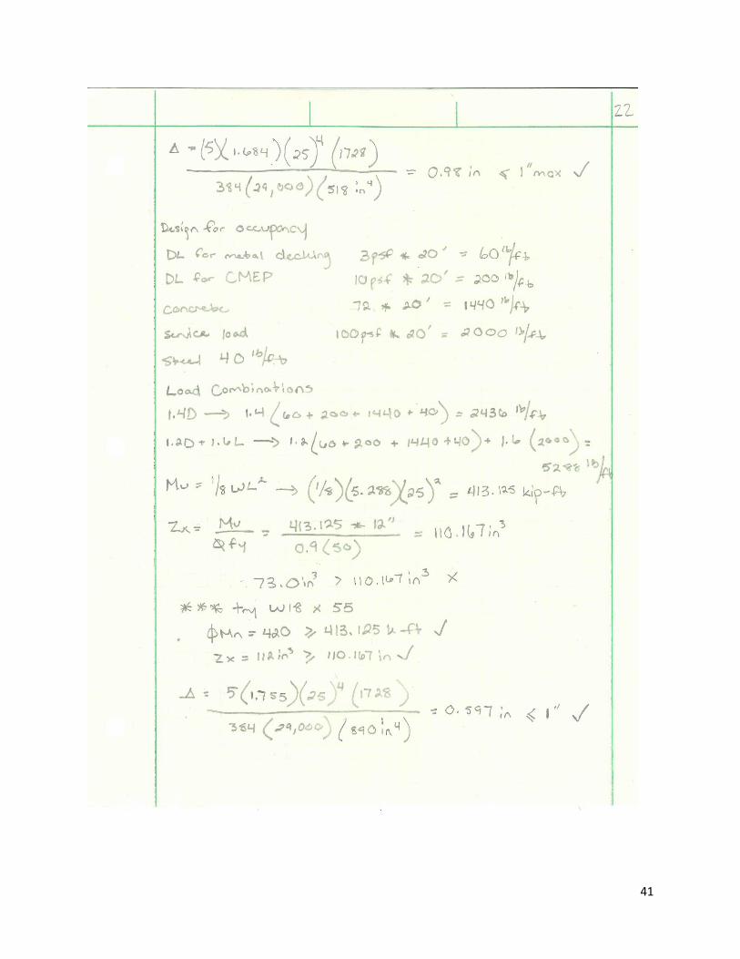
41

42

43

44

45

46

47

48

49

50
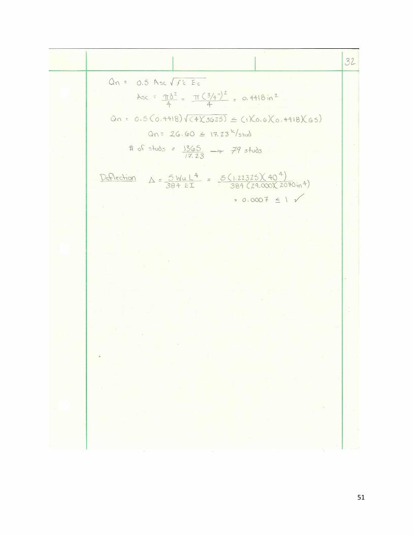
51

52

53

54
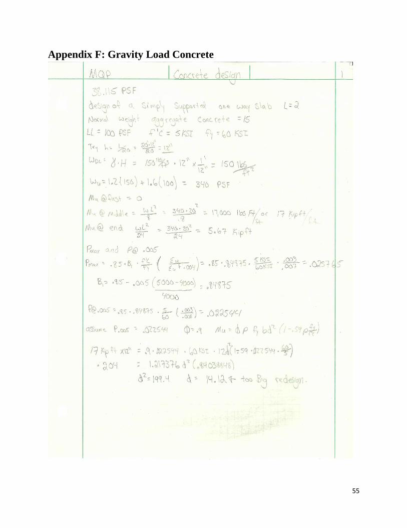
55
Appendix F: Gravity Load Concrete

56

57

58

59

60

61
Appendix G: Seismic Load

62
Appendix H: Lateral Load Steel

63
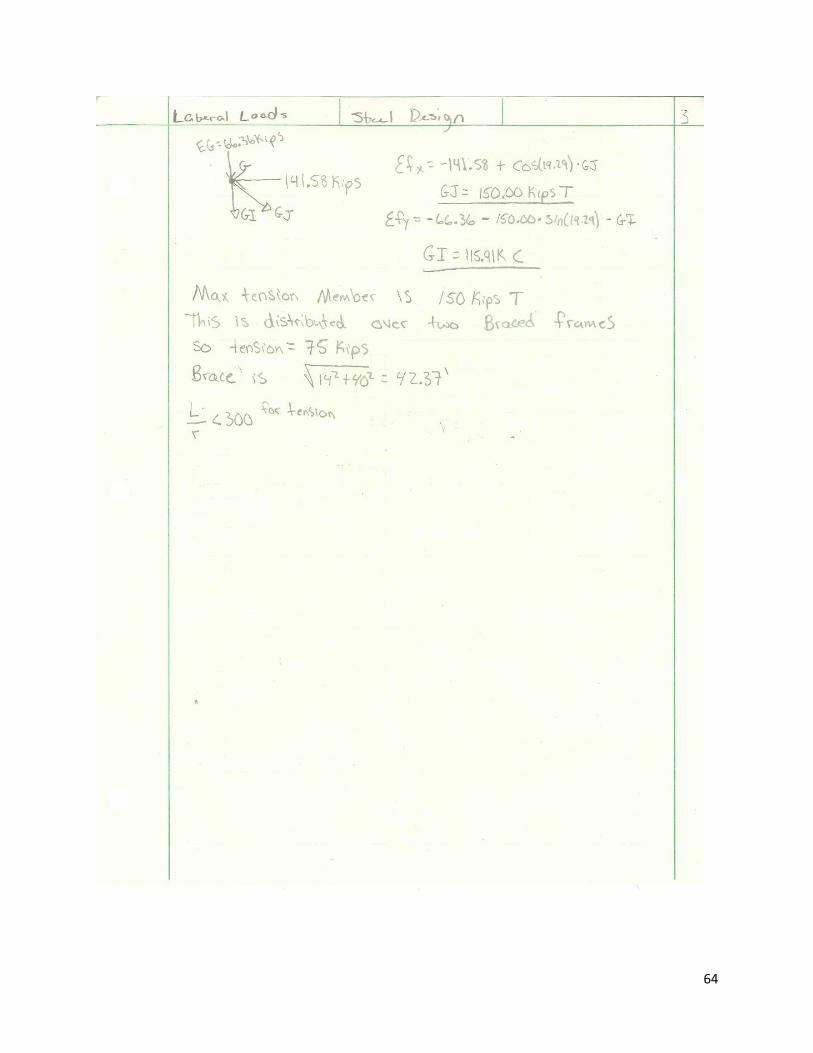
64

65

66
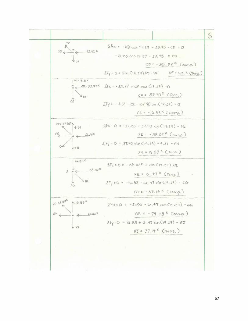
67

68
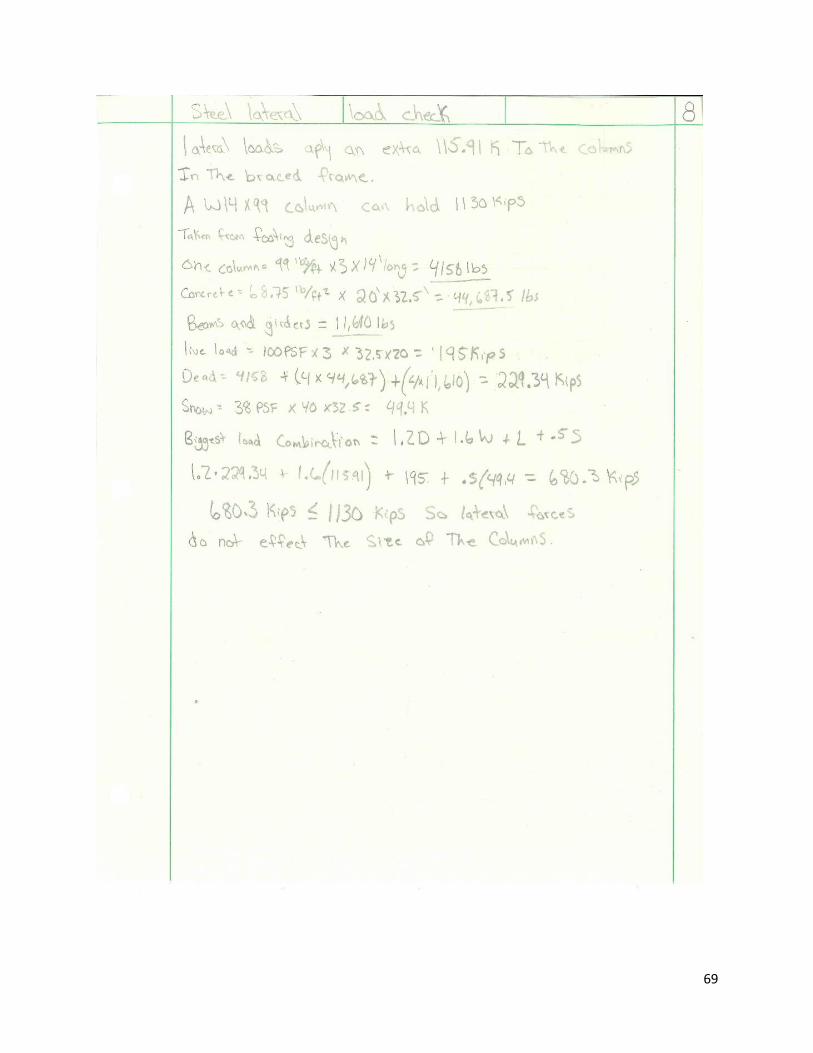
69

70
Appendix I: Lateral Load Concrete

71

72

73
Appendix J: Footing Design

74

75

76
Appendix K: Material Takeoffs

77

78
Appendix L: Cost Estimate

79
Appendix M: Schedule Activity List Activity Name
START PROJECT
Erect Fence/Prep Site/Erosion Control
Relocate Utilities
Backfill/Restore Grade
Excavate for Foundation Wall
Excavation for Spread Footings
Backfill Int. Fnd. Walls & U/G Duct
Form/Place/Strip Spread Footings
Form/Place/Strip Foundation Walls
Concrete Curing
Dampproof & Insulate Foundation
Fabricate & Deliver Steel
Erect Basement Steel
Erect First Floor Steel
Erect Second Floor Steel
Erect Third Floor Steel
Install First Floor Deck/Studs
Install Second Floor Deck/Studs
Install Third Floor Deck/Studs
Install Roof Metal Decking
Prep/Pour Main Slab on Grade
Prep/Pour First Floor Slab on Deck
Prep/Pour Second Floor Slab on Deck
Prep/Pour Third Floor Slab on Deck
Install Roof Decking
Install Slate Shingles
Install Precast Supports / Adjust
Install Windows
Exterior Walls Insulation Panels
Install First, Second, Third Floor Brick - E/W/N/S
Install Stairs/Areaway Grates
Install Stair Rails
Install Doors & Hardware
Install Drywall
Paint - Finish
Install Wood Paneling
Install Elevator
Install & Complete Flooring
Paint - Prime
Install HVAC Duct/Piping
Install Electrical
Install Plumbing
Install Telecommunications

80
Install Fire Protection
Mechanical Finishes
Fab. & Del. Auditorium Seating
Ext. Lights W/E Entrances
Install Signage Building
Owner Furniture
Exterior Finishes, Plantation & Grading
Landscaping & Brick Paving
Place Exterior Concrete Sidewalks
Place Exterior Site Concrete
Test & Balance Building - Bldg
Punchlist - 1st flr
Punchlist - 2nd flr
Punchlist- 3rd flr
Final Clean - 1st flr
Final Clean - 2nd flr
Final Clean - 3rd flr
Commissioning Building
Flush Building
Substantial Completion Cert. of Occup.
WPI Move - in
Building Dedication
END PROJECT