written steve fitzwilliam date: 05 i i reviewed by: cree corcoran … · · 2006-07-18hangers...
TRANSCRIPT
GEOSYNTEC CONSULTANTS page I of 4
Written by: Steve Fitzwilliam Date: 05 I 10 1 2 I Reviewed by: Cree Corcoran Datc: I I YY MM DD YY MM DD
Client: Slourzh Project: Britannia East Grand ProjectlProposal No.: SC0347 Task No.: 1
PIPE HANGER DESIGN
OBJECTIVE
At the proposed Britannia East Grand development site in South San Francisco, California, pipe hangers suspended from the concrete structural slab will support the air inlet and gas extraction pipes beneath the buildings at the Site. The pipe hangers will be installed during the construction of the gas control system.
The design of the pipe hangers takes into consideration two controlling factors; the spacing of the pipe hangers such that the pipes do not deflect more than I", which is half the diameter of the pipe, and the maximum allowable load each pipe hanger can support.
SUMMARY OF ANALYSIS
The analysis suggests that the pipe hangers used for this project need to support at least 45 Ibs. if there is 1 inch of soil located between the top of the pipe and the concrete slab. In addition, the pipe hangers need to be spaced approximately 8 ft. apart such that the PVC air inlet and gas extraction pipes do not deflect more than 1".
SITE CONDITIONS
The components involved in this analysis are the following, from top to bottom: - 10 inches of structural concrete slab; - protection course (a nonwoven needle-punched cushion geotextile); - 80 mil Liquid Boot geomembrane; - heat bonded nonwoven carrier geotextile; - 3 to 6 inches of gas extraction sand and aggregate; and - 2-inch diameter PVC pipe.
A cross-section of the gas control system is presented as Attachment A.

GEOSYNTEC CONSULTANTS Page 2 of 4
Written by: Steve Fitzwilliarn Date: 05 I 10 121 Reviewed by: Greg Corcoran Date: I I YY MM DO YY MM DD
Client: Slouah Pro-iect: Britannia East Grand ProjectiProposal No.: SC0347 Task No.: I
ANALYSIS
PIPE HANGER SPACING
The spacing of the pipe hangers is controlled by the maximum allowable deflection of the pipe. The deflection of the pipe is due to the weight of the pipe itself (Attachment B), as well as the weight of the soil on top of the pipe. Depending on the type of pipe hanger selected, soil may be located between the pipe and the bottom of the concrete slab. For the purposes of this analysis, it is assumed that 1 inch of soil will separate the top of the PVC pipe and the concrete structural slab.
The equation used to calculate deflection for a distributed load is:
(Attachment C)
Where: v,,, = maximum deflection (inches) q = distributed applied loading (poundslinches) L = length of pipe (inches) E = modulus of elasticity (pounds/inches2) 1 = moment of Inertia (inches4)
EVALUATE EQUATION
v,,, = 1" - (to allow air flow if water infiltrates pipe)
q = weight of pipe + weight of soil on top of pipe
Weight of pipe = 0.695 Iblft = 0.058 lblin (Attachment B)
Weight of soil = (d)(+)(ySoil)
where: d = depth of pipe, assumed to be 1" + = outside width of pipe = 2.375" y,,it =unit weight of soil, assumed to be 125 lbs/ft3
Weight of soil = (1 in.)(2.375 in.)(125 lbs/ft3)(1 ft3/1728 in3) = 0.172 Iblin
E = 400,000 lb/in2 (Attachment D) - .. ~
P:IPRJSDWPlCvrrenl ProjeclslSClJ347 B~.ilonnio ,?as! Grand Ph illCaleslPipehangerdoc

GEOSYNTEC CONSULTANTS Page 3 of 4
Written by: Steve Fitzwilliam Date: 05 I 10 1 2 1 Reviewed by: Grep Corcoran Date: I I YY MM DD YY MM DD
Clierlt: S l o u ~ h Pro.iect: Britannia East Grand ProjecVProposal No.: SC0347 Task No.: 1
I = 0.666 in4
Plugging in the variables,
(Attachment E)
L = 97.1 in = 8.1 ft.
Therefore, the pipe hangers should be spaced every eight (8) feet.
0 PIPE HANGER STRENGTH
The maximum load each pipe hanger should be able to support is equal to the weight of the PVC pipe and overlying soil over the distance between pipe hangers, plus a factor of safety of 2.0. Therefore, each pipe hanger for pipe 1 inch deep should be able to support: (0.230 lbslin)*[(8 ft.)(12 in./ft)]* (2.0) =

GEOSYNTEC CONSULTANTS Page 4 of 4
Written by: Steve Fitzwilliarn Date: 05 I I0 I21 Rcviewed by: Greg Corcoran Date: I I YY MM DD YY MU DD
Client: Slouch Project: Britannia East Grand Projectmroposal No.: SC0347 Task No.: I
CONCLUSIONS
Assuming the following:
the maximum allowable deflection of the PVC pipe is 2 inches; and 0 1 inch of soil are located between the top of the pipe and the concrete slab
The pipe hangers should be spaced 8 ft. apart for solid wall pipes. In addition, the pipe hangers need to support a maximum load of 45 ibs. Perforated pipes will drain, so no hangers required.
PIPE HANGERS THAT MEET REQUIREMENTS
The following is a partial list of pipe hangers that meet the property values stated above:
Standard Clevis 4" Hanger, with a work load limit of 1430 lbs.
REFERENCES
ASTM D 1784 - 92 "Standard Specification for Rigid Poly (Vinyl Chloride) (PVC) Compounds and Chlorinated Poly (Vinyl Chloride) (CPVC) Compounds", American Society for Testing and Materials, Philadelphia, Pennsylvania, USA
Harrington, PVC Pipe - Schedule 40 Properties
Sack, R.L. (1984) "Structural Analysis," McGraw-Hill, Inc., New York.
P:lPRJlSDWI'ICurrenl ProjeclslSC0347 Brilannia Easr Grand Ph IllCalcslPipehongerdoe

PIPE HANGER
2" DIA. SCH.40 PVC PIPE (NOTE 2)
GEOMEMBRANE
. . - -.
........... - ...... .- - - ...... .... .... -. - -. - - ....... . .. . -~ ..... -- .- -. ...
......... .... ....
SECTION GAS EXTRACTION SYSTEM N.T.S.

PVC PlPE - SCHEDULE 40
PVC is the most frequently specilied of all plastic piping materials. It has been used successfully for over 30 years in such areas as chemical processing. induslrial plating, chilled water dislribution, deionized water lines, chemical drainage, DWV piping, and irrigation syslems. PVC is characterized by high physical propeiiies and resislance l o corrosion and chemical attack by acids, alkalies, salt solutions and many olher chemicals.
PVC used in plastic piping is: T y p e 1, Grade 1 PVC (Cell Classiiication 12454.0) . Conforms to ASTM D-1784
The maximum service temperature for PVC Is 1409. PVC has the highest long term hydrostalic slrength at 73" of any ofthe major thermoplastics being used for piping. PVCpiping is joined by solvent cemenling or threading.
SCHEDULE 40 PVC PlPE - Conforms to ASThl D-1785. Type 1 (normal impact). Grade 1 (high chemical resistance). This pipe also conforms to U.S. Product S:andard PS 21.70 (sqersedes U.S. Cor;::cial Siandaid CS 23743) 2s having ihe same O.D. dimensions as iron pipe. Tce Na!ionai Sanit2:ion Foundelion (+IS?) has e??;oved pipe sizes i/:' ihru 1ii' for use in po!aSle water service. Schedule 40 pipe should not be threaded.
1
18' 1 400-180 1 10,887.00 1 2111.0 / l j 3 / 18.00 / ,552
2Cr 1 400.200 / 12,793.00 / 2490.0 1 123 1 20.00 / ,593 I 2:' 1 400-240 1 16,507.00 1 3451.0 1'2.3 / 2:OO 1 ,657 i
I.;OTES: 1. S!andard leng!h 20 (el. 2. Pi?. sizes l i ' , 3:6. and 3.112' a:o ciay in m t x A: 03.: Fi;e i s n3ina!!i. whi!?. 3. Pipe maj. b? d a i n or belled end. 4. 14' and 2:' piae has been nDpr?ued b y the Canadian S:andardj Ai;:ria:ion ICSA) far coia~le w:er sewice.

Therefore, C, = - M , L C: = f iLllL1
At the free end
= 0.12 in ( T )
(2L = -0.0016 rad = -0.09" (n)
Dlscusslos This is the same beam as i n Example 9.2, but i t is loaded with a concenr;3t:d moment at the free end. I n this case, the moment deforms the beam into a positive curvatur: o w the entire length. The same geometric-compatibiiiiy conditions used in Example 9.2 wers used here to evaluate the inlegration constmts. The maximum deflec~ion of 0. 12 in occurs at the free end. u.hsre the maximum slope o i -0.0016 also occurs.
Example 9.4 Find !he Wrn d-Fi?rbn and slope for this simply.suppon:d k 3 n .
Elv = - &s;' + 54Lr' + C,r + C:
r(0) = 0 I(L) = 0
C , = - A ? ' ' c 2 = 0
Elr. = 2 iq . r -s ' f 2 ~ r : - L ' )
Sicse r lvldr = 0 at .r = ! L . r,,, occurs there. .+
'2
S t k , \q 8 4

= 16.SS x lo-' m
= 4.5 X 10" rad = 0.26'
D~scusslos This symmetric beam is bent into positive curv3rure over its entire lsngih by lhe uniform loading. The zero deflections at the two suppons a;e used to evaluate the ronstmts of integration. The deflection expression turns out to be a quanic polynomial wilh the mzximum deflection occurring at* = L / 2 ; the slope has its maximum rnagnirudcai both suppons and a zero value at x = L / 2 . The dimensions and size of the steel beam shown result in a maximum deflection o f 16.85 mm with a maximum magnitude of slope equal to 0.26' a[ the tuw suppons.
This method is more cornpiex for a beam with 8 joading like rhai shown in ~ i g . 9.5. In this case the moment expression for the moment between points a and b diiisrs from lhat for ine moment between points b and c; therefore, the moment- curvature relation must b e integrated individually for each segment. This process gives four constants of integration to descr ibe the beam disp!arsm?nls. Two of these cons:mts can be evaluated by e n f o r c i n ~ the conditions of zsro d i sp lxement at the q p i ) : ~ , and tkr orhsr t w o must b s e v ~ i u t e d by na;chinz the expressions at point b is: fi,: slops 2nd d:flection. S incs th-re 2:s morz el::mr r a s h s o x i c a t ways OF . . oba !n !n~ tils e.k?:essionj for disp!zsnre,?r 312 s!o- r - isr tkss: t f l : ~ of p:oblsms, L?: r z d e i i;.ho iots;-& to IS: this n e t h o d extsnjii.:!!. \i.ouiJ b s wiss 13 study the
- . a.>?!~:ar:isn o f sin:u!zity ic ; : ; ionj 13 iL.:s: ~ : i l j ! : z j (SS fz: : x35? !2 . Rsf. 2 ) .
9.4 THE PRIXCIPLE OF SUPERPOSITIOS
l i e strucrure is acted upon by a nunlbsr o f individual lo::es ccd!or moiiietls, the lola\ d:fii.:rion of rh? siruciur: can be obtain-d b;; cz!cu!l!inp the dsflscrions induced by each o l ths individual f o x e s and addin? thz rcjiii:j. Tb,is process o f combining soluiims lo; 2 ziven problem is called riipcrpos',io,,, 2nd th: \.aiidi;y of the approach depends upon the linearity o f the s t ructurs . Figure 9.60 a:id 9.6b shows l o ~ d - dsfo;iii~iion @ $ i s fo r a linsar nod a nonlinear stiu:iii;~l response, res;?:ctive!y..Y!e can 8:s ih2t for the i i n s x stiuctu;: 2n applied 1026 P aili give th: dsfomarior! A r:ga:dless of where in the loading process i t is applied. For nonlinc-isitoation the s m s lo2d P will g ive dif isr tnt d e f o m a r i o n j , 3, 2 - 2 A:. \vIiich dspsnd upon the cmocnc of losdio: prer,iously applied to ths Srructcr?, i\(on!in:xitirs can be introduced

: foliowing
I L AQL
2.5 2 2.5 1 1.5 I * ... nd poolcd [a,
ei/b Des igna t ion : D 1784 - 92
Standard Specification for Rigid Poly(Viny1 Chloride) (PVC) Compounds and Chlorinated Poly(Viny1 Chloride) (CPVC) Compounds1
Thir r u n d l r d ir iuucd uodcr the l i d dcrign%lion D 1734: the n u m k i immtdirlely f ~ i l o ~ i n g lhc daiqnalian indicarcr rhc year 0: oiiy'nd ~dap i i an or. in thc cow of rcvilion, r h ~ ycm of la rcvkion. A a c m k i in pucnthcwr iodiraus :he y c u o f l m ruppmvd. A rupcr iu ip l cprilon (4 indicatcr an cdirorid chmgc lincc :he IUI rcvirion or rczpprovd.
1. Scope 1.1 This specification covers rigid PVC and CPVC com-
pounds intended for general purpose use in extruded o r molded form, including piping applications involving special chemical and acid resistance or heat resistance, composed of poly(viny1 chloride), chlorinated poly(viny1 chloride), or vinyl chloride copolymers containing a t least 80 '3 vinyl chloride, and the necessary compounding iniedients. The compounding ingredients m2y consist of lubricrnrs, s ~ b i - lizers, non-pol!.(vinyl chiorid:) resin modifiers, pi:rnenis an3 inorgmic fil!::j.
D 39 l j 4336. 1.3 Rigid PVC compounds intended for building product
a~ol ica t ions are co;.ered in Sxcification D 42 16. . . 1.4 T h e valuts sta;d in SI units ars to be resarded 2s th:
standard. The values given i , ~ . pmnrhsses are for in foma- fion only.
1.5 T h e foIl&.vin: sdsiy hzzxds c2ve2t pertains only to the test methods ponion, Section 1 1 , o: this specificalioa: TAij srcndcrd &s mi p!ir,-or: ro cddress a!! of (he saJ2:. probkrns, if any, asiocioced wiih i:s iije. It is the resgotui- .bi!iiy of !/re i m r of r1:is s:ci:riard ro es!ob/is/i cppropricre .~nfeiy a n d heaid: pracrices a d derernline rlre cpplicabiiiir. q l repil!arory 1irnitc:iorrs prior 10 rise.
NOTE 2-This rp:ci5ca:ion ii sir ; . i ix in conen: (bu! not irchnica!lj cquir l ien: ) ro IS0 1163-t:i9Sj ar.5 IS0 i 163-?:1930.f
2 . Referenced Documents
2.1 ASTM Srondards: D 256 Test Evlethods for Impact Resistance of Plastics and
Elsctrical Insulating hk~ t s r i a l s~
D471 Test Method for Rubber Propeny-Erect Liquids'
D543 Tesr Method for Resistance of Plastics to Ch-m:. - - . . . . . Reagents3
D618 Practice for Conditioning Plastics e n d El:&; Insul3tini: Materials for test in^'
D 635 ~ e s t Liethod for Rate of Birning and/or E:~:nt a: Time of Burning of Self-Supporiing Plas;ics i r 2 & zonul Position1
D63S Tesr hlethod for Tensile Properties of Pi?rii:sj 3 5 4 S Tes! bfsthod for D-flection Teniler2:~ir: c ; F;:i:i
DSS3 Terminolo~? P,elatinz to Plrs'.ics3 D 1600 Temino1o:y for Abbreviated Tezi Zr:z:i:,- :
Pls:icsl D 189s Practice for Smipling of Plastic? D 1921 Test Methods for Particle Size (Sieve .~n.::.sis! ;
PIzstic Materials' D 3S92 Pracrice fo; PackaginUPacking of Pirs;i:j5 Dj915 Specification for Poly(Viny1 Chlorids) (Pi 'C) 2:
R:l:tsd Pkstic Pips and Fittinz Comuou;?i f ~ r P;? - silre Applications7
D:?16 Specification for Ri& Poly(Vinyi C h k d ? ) (?\'C 2nd Related Pivtic Building Products Cor-.a-:<j7
Dl j96 Sxcification for RiGd PolvNinvl ChloAds) (PVC
ing Products7 Dj?60 Classification for Chemical Resistz:.:? c' Pd:
(Vinyl ChJoride) (PVC) Homopolymer a n d C o s s l ? ~ ~ Compounds and Chlorinated Poly(Vin:l Ck!ofid?
unkss othsnvise indicated.
3. Cl3ssification 4.1 h1:aos for sslecting and identifying rigid ?'\C c"'

l!G pue huado~d

I lo\\ing. shall be o n the basis of agreement between the prchhser and the seller.
.
5.2.1 Physical form and particle size (see 6.1). 5.2.2 Contamination level (see 6.2), 5.2.3 Color (see 6.3), 5.2.4 Other supplementary definition if necessary, and 5.2.5 Inspection (see 12.1).
6. hlaterials and Manufacture 6.1 Materials supplied under this specification shall be
pVC compounds in the form of cubes, granules, free-flowing powder blends, o r compacted powder blends.
6.2 Materials shall be of uniform composition and size and shall be free of foreign matter to such level of contami- nation as may b e agreed between the purchaser and the seller.
6.3 Color a n d transparency or opacity of molded or extruded articles formed under the conditions recommended by the seller shall be comparable within commercial march tolerances t o t h e color and transparency or opacity of sundard molded o r extruded samples of the same thickness supplied in advance by the seller of the material.
7 . Physical Requirements 7.1 Test v d c e s for specimens of the material prepared as
s:eciiisd in Section 9 and tested in aciord?nce with Section ll? shs!l c o n f o m to the requirements g v e n in Tablss I er.6 2 hi the class se1sc:ed.
. Samplin: 8 I A b3tch o: lot shall be considered as a unit of
rznufacture and may consist of 2 blend of two or more production runs of materia!.
8.2 Unless otherwise ageed upon between the seller and 13.: purchaser, the material shall be sampled in accordance ~;.!h the procedure described in the Gzneral and Specific Sampling Procedures, as applicable, of Practice D 1898. Adequsts statistical mmpling prior to packzing shzil be considered an acceptabk altenativs.
9. Testing 9.1 The requirements identified bj. the class designation
2-d othenvis: specified in the purchase order (see 5.1) shall k verified by tests made in accordance with i'ne directions C ~ e n in Section 1 1 . For routine inspection, only those tssts necessary to identify the materials to the satisfaction of the Purchaser shall be required. One sample shall be sufiicient
testing each batch or lot provided that the average values fa; all of the tests made on that batch or lot comply with ths s??cified requirements.
9.2 If any failure occurs, the materials may be retesttd in accordance with a g e e m e n t between the purchaser and the ZUer (see 12. I) .
10. Specimen Preparation 10.1 Compliance with the designated requirements
'iOsen from Tables 1 and 2 shall be determined with mpression-molded test specimens. Procedures used in
Jeparing the tsst specimens shall be as recommended by the X k r . The procedures shall bc the same for all test specimens Wuirsd by Section I I . Test specimens shdl conform to the
rcquiremcnts prescribed in Sectibn I I . 10.2 Subject to agrezment between the purch~ser a n d
seller. tests may be made on specimens prepared frocl finished molded or extruded articles. Results of such tests may not agree with the values given by specimens prepared in accordance with 10.1. Therefore, in reports ofsuch tests. methods and conditions o f preparation, dimensions, and dl other pertinent information shall be included. compression molding shall be the referee method.
11. Test Methods I 1.1 Conditioning-The test specimen for deflection t e n -
perature (Test Method D.648) shall be conditioned in accordance with Procedure B of Methods D 618, except tha t the minimum conditioning time in the circulating air oven shall be 24 h. All other molded test specimens shall be conditioned in accordance with Procedure A of Methods D 618. The minimum conditioning time shall be 24 h.
11.2 Test Condilions-Unless otherwise specified in t h s tssting mzthods or in this specification, tests shall b s conducted in the Standard Laboratory Atmosphere of 2 3 t 2'C (73.4 ? 3.6'0 and 50 2 5 % relative humidity. In cases o f d i s ~ g e e m e n t , the tolernnces shsll be a l ' C (rtl.8"Q a n d =1 % rel3tive humidity.
I I .3 Tensile S!reng!i! c c d i\Iod!i!!is 0.T El"s!ici!y-Tes: ?.!sthod D 63S, csi3: T)?e 1 speciae;s. sn-; 6 r ,-..... ,,-. ;,'...,-..,, ...... - L ~ . , u s . . i,.?->,,.- w--L LU - sz-%zsn ~hickncss d 3 . 2
= C:.' i ; . ~ (0.13 + 0.22 i-.) 2:d 2 s ; c r l or I x i ? : o i 5.1 nn. (0.29 i. ,;-:.. ,i c ...., ..... . - -, ,..
1 I ..i F/e.ri!rc! Yi:!d S!r?n:ii!--Procedu:: B oFTest blztk- cdi D 790 usin: 12.5 by 3.2 mm (I;? b;; ';2 in.) specimens, 2 i:. s p n at 1.3 mn/min (0.05 in./rnin).
I 1.5 impcr! Stre-p!h (Izodj-Method A of Test Methods D 256, using 6.3j-mm (0.25-in.) thick specimens. The spec- i-izns rnzy be compression- or injection-inolded with rhs provision that compression-molded spcimens built u p es 1:minat:s i n which complete fusion is obtained shall be 2:c:;)tzble. Coxpj2:s fusion means theis shali be no evi- dsnce or fraying or dslasnination at the br$$i.
1 1.6 Defic!ion Temperc!frrr-Test Method D 648 usin: I ? j by 3.2 rnm (':: k; '1'3 in.) specimens undsi 1.82 MPa ( 2 6 2 pi) load.
11.7 Flammab'!!:j-Test Method D 635. 11.8 Ciiemico!Resisianre-Test Method D 533, using the
I-st specimen 25.4 by 76.2 by 3.2 m m (I by 3 by '/a in.) a n d ih: tsst conditions and rtagsnts specified in Table 2 es fol!o>vs:
11.8.1 Slihiric .-!rid (93.0 %)-The acid shall be 66' Bzumi. (92.98 to 93.41 % sulfuric acid (H,SO,) sp &r 1.836; to 1.8341 at 60160'Q. The specimen must be completely immersed i n the ecid.
11.8.2 Siififric Acid (80 %)-The concentration of 80 5% H,SO, is not critical but must be held to an 8'3 i 2 % level to .- - - nest the requirem:nts of this specification. The samples must be immersed completely. G l m or acid-resistant wire nzi. be used for sinkers.
II.8.3 Adj!rs!n:?~:l of .4cid S!rrng!i!-The HJO, conten! of thr acid solutions may be determined by titration with sodium hydroxide (KaOH) soLiltion and methyl- oran$$ i-disator or byspecilic gravity with hydrometers sensitive 2;:J X U ! t I I . The tl:SO, contenr should bc

adjusted to the required strength by mixing dilute and concentrated acids.
11.8.4 ASTM Oil No. 3-ASTM Oil No. 3 shall meet the requirements prescribed i n Test Method D 471.
1 1.9 Parlick Size (Sieve Analysis of Plastic ilfa~eriafs& Test Methods D 192 1.
12. Inspection 12.1 Inspection of the material shall be made.= agreed
upon by the purchaser and the seller as part of the purchase contract.
tion at the lowest rate to the' point of delivery, unlen. oihen%ise specified in the contract or order. '
13.2 Marking-Unless otherwise agreed upon betwe,,' the ~urchaserand seller, shipping containenshall be marked wirh the name of the material, and the name o r manufacturer, class, batch or lot number, quantity contained therein, as defined by the contract or o rdermder whic.n shipment is made, the name of the seller, and the number . . the contract or order. ' .ii
13.3 AU packing. packaging. and marking provisions o f
Practice D 3892 shall apply to this specification. .. x . . . . ' I
. . . : . : ,- ,; . . . .
13. Packaging andpackage Marking 14. Keywords . . . . L .., 13.1 packaging- he matkriq shall be in stan- 14.1 chlorinated pbfy(viny~ ,chloridk) (CPVC); c~$:Z
dard commercial coniainen, so constructed as to ensure compounds; poly(viny1 chloride) (PVC); PVC compounds;. acceptance by common or other carriers for safe transports- rigid PVC
:.;> :,:; . . . , : ., .!
APPENDIXES .. ., I ' :.:
(Nonmandntory Inforrmtion)
XI. CLASSIFICATIOS O F CONbIERCIAL Tx'PES AXD GRkDES OF RIGID POLY(YIhTL .CHLORIDE) CO>lPOU&DS
TABLE X1.1 Comparison of Fomer a n d New Designations
Fcmer Ccmmercid Ty= anb Gee? '.- ,.-n Fcr;;er SF?--tw::cc . C!ai; I ; :nTat ic I
n r m - R ; T
T y p I . Grade 1 T y x I. Grade 2 Ty? I. Grade 3 T y y 11. Grade 1 Type Ill, Grade 1 Ty? IV. Grade 1 Ty? V. Gmde 1
CO>IbIERCI.<L Tlr'PES AXD GRADES OF RlGlD V I h ' Z CHLORIDE . . . ., TABLE X2.1 Comparison of Former a n d New Designations ., . ,
Fomer Ccnmercial Ty% and Gilt .? 1:im Fcmei Swci5ca:icn Class ham T a m 1
Ty:'? I, Grad* 1 51332 Tvre I Dirde 2 51331 , ? ~ . - -~~ -
Tyi'? 11. Grade 1 TYM 11. Grade 2
This slanddrd is subjec: lo revision 21 any rime b y !he rs$poosib/e lchc ica l c a r n m i r ~ and mu81 be reviewed every live yeus and if no1 rs.ds?d, either reagprovd or wi thdmm. your comrnenli are iov i rd edher lo, rwb ion of (his standard or lor addilionalslandards and shooid be addressed lo ASTM Headquaneis. your comrnen~s will recei,,. caielul coosidefalion sr a meeting of the responsibls ri.chnica1 c o m r n i " ~ , which you may anecd. 11 you lee1 that ycor commem have nor received a lair hearing you should make yaw v ie rs known lo lhe ASTl.1 Cornminee on Slandaids. 1916 Race SI.. PhiIad4pl;ia. PA 19103.

GEOSYNTEC CONSULTANTS .- . . . Page of
Written by: Date: / I Reviewed by: Date: I 1 YY MM OD YY hlM DD
Client: Project: Project/f'roposal NO.: Task No.:

GEOSYNTEC CONSULTANTS Page I of 7
Written by: Steve Fitzwilliam Date: 061311 5 Reviewed by: Gler Corcoran Date: I / YY MM DD YY MM DD
Client: Slough Estates USA Inc Project: Britannia East Grand Ph 11 ProjcctiProposal No.: SC0347 I'askNo.: 01
GEOTEXTILE PUNCTURE PROTECTION OF LIQUID BOOT BUILDING 2
OBJECTIVE
At the proposed Britannia East Grand development site in South San Francisco, California, an 80-mil (2.0-mm) Liquid Boot cold spray applied geomembrane gas barrier will be subjected to forces, such as foot traffic, steel reinforcement and poured concrete that may damage the Liquid Boot geomembrane. The Liquid Boot geomembrane will be spray applied to a heat bonded nonwoven carrier geotextile, which will sewe to protect the geomembrane from puncture. In addition, a nonwoven needle-punched cushion geotextile will be installed over the geomembrane gas barrier to protect the geomembrane gas barrier from damage during installation of the overlying reinforcement and concrete slab. The objective of this calculation is to evaluate the required puncture strength of both the heat bonded nonwoven carrier geotextile and the nonwoven, needle-punched cushion geotextile.
SUMMARY OF ANALYSIS
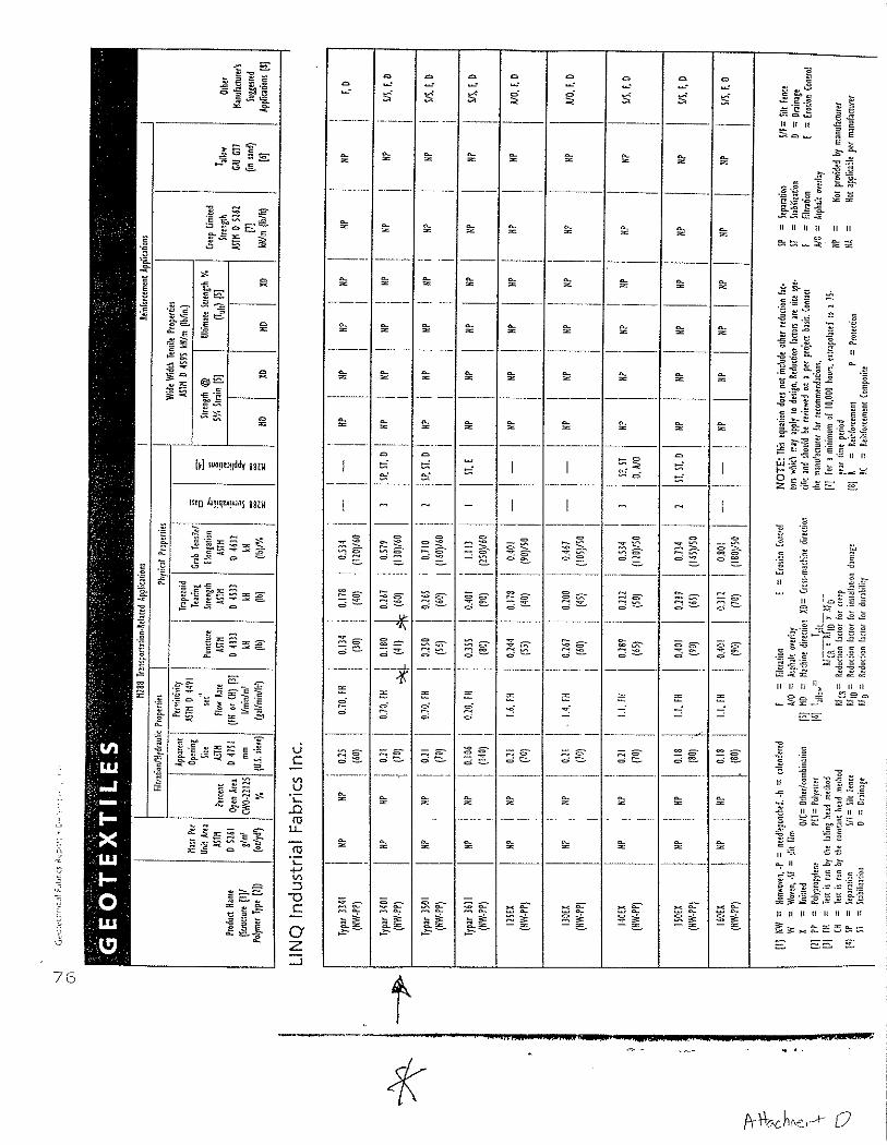
The analysis suggests that the puncture strength of the heat bonded nonwoven carrier geotextile be greater than 41 lbs. for Linq 3401. The analysis also suggests that the puncture strength of the nonwoven needle-punched cushion geotextile be greater than 78.0 lbs, for 10 odyd2. A summary of required geotextile properties and a list of geotextile products that meet the material requirements are provided at the end of this calculation package.
SITE CONDITIONS
The components beneath the building are the following, from top to bottom: - 10 inches of concrete; - protection course (a nonwoven needle-punched cushion geotextile); - 80 mil Liquid Boot geomembrane for calculation (minimum thickness
recommended 100-mil) - heat bonded nonwoven carrier geotextile; and
A cross-section of the gas extraction system is presented as Attachment A.
GEOSYNTEC CONSULTANTS Page 2 of 7
Written by: Steve Fitzwilliam Date. 0613115 Reviewed by: Gree. Corcoran . Date: 1 I YY MM DD YY MM DD
Client: Sloueh Estates USA Inc Project: Britannia East Grand Ph I1 Project/Proposal No.: SC0347 Task No.: 01
ANALYSIS
OVERLYING PRESSURE:
The gas barrier system will be overlain by a nonwoven needle-punched cushion geotextile and a 10 inch concrete floor slab. The maximum loading will be no greater than the loads associated with the construction of the concrete structural slab. The construction loads include foot traffic, steel reinforcement and associated support, and the load of the concrete. This pressure will be exerted directly on the geotextile/geomembrane.
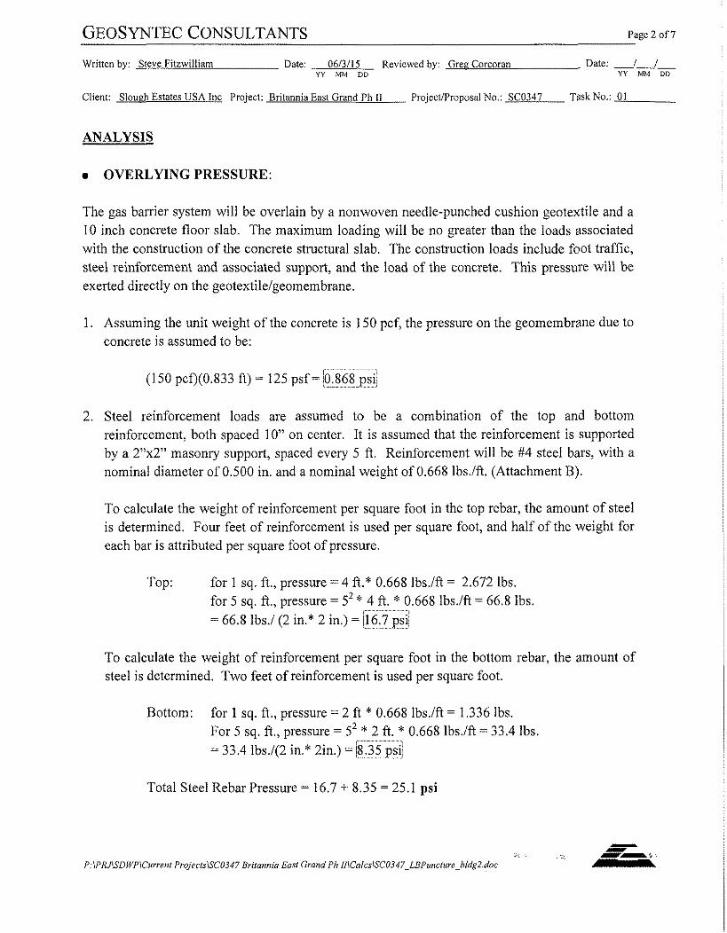
1. Assuming the unit weight of the concrete is 150 pcf, the pressure on the geomembrane due to concrete is assumed to be:
r--" ' ~ ~ ~ ' ' (150 pcQ(0.833 ft) = 125 psf =.0.868 ....................
2. Steel reinforcement loads are assumed to be a combination of the top and bottom reinforcement, both spaced 10" on center. It is assumed that the reinforcement is supported by a 2"xY masonry support, spaced every 5 ft. Reinforcement will be #4 steel bars, with a nominal diameter of 0.500 in. and a nominal weight of 0.668 lbs./ft. (Attachment B).
To calculate the weight of reinforcement per square foot in the lop rebar, the amount of steel is determined. Four feet of reinforcement is used per square foot, and half of the weight for each bar is attributed per square foot of pressure.
Top: for 1 sq. ft., pressure = 4 ft.* 0.668 1bs.ift = 2.672 lbs. for 5 sq. ft., pressure = 52 * 4 ft. * 0.668 lbs./ft = 66.8 lbs.
....................
= 66.8 lbs./(2 in.* 2 in.) = i16.7 ...................... psi
To calculate the weight of reinforcement per square foot in the bottom rebar, the amount of steel is determined. Two feet of reinforcement is used per square foot.
Bottom: for 1 sq. ft., pressure = 2 ft * 0.668 lbs.ift = 1.336 ibs. For 5 sq. ft., pressure = 52 * 2 ft. * 0.668 lbs./ft = 33.4 lbs,
......................... i
= 33.4 lbs./(2 in.* 2in.) = 18.35 ............... psi1
Total Steel Rebar Pressure = 16.7 + 8.35 = 25.1 psi

GEOSYNTEC CONSULTANTS Page 3 of 7
Written by: Steve Fitzwilliam Date: 0613115 Reviewed by: Gree Corcoran Date: I I YY MM DD YY M M DD
Client: Sloueh Estates USA inc Project: Britannia East Grand Th I1 ProjecWProposal No.: SC0347 Task No.: 01
Based on the above calculations, the combined pressure resulting from the concrete and rebar dead weight will be used to design the required cushion geotextiles. The combined pressure is:
(0.868 psi) + (25.1 psi) = 26.0 psi
APPROACH
CUSHION GEOTEXTILE
The cushion geotextile will s e n e to protect the Liquid Boot geomembrane from puncture by the 2"xT masonry blocks.
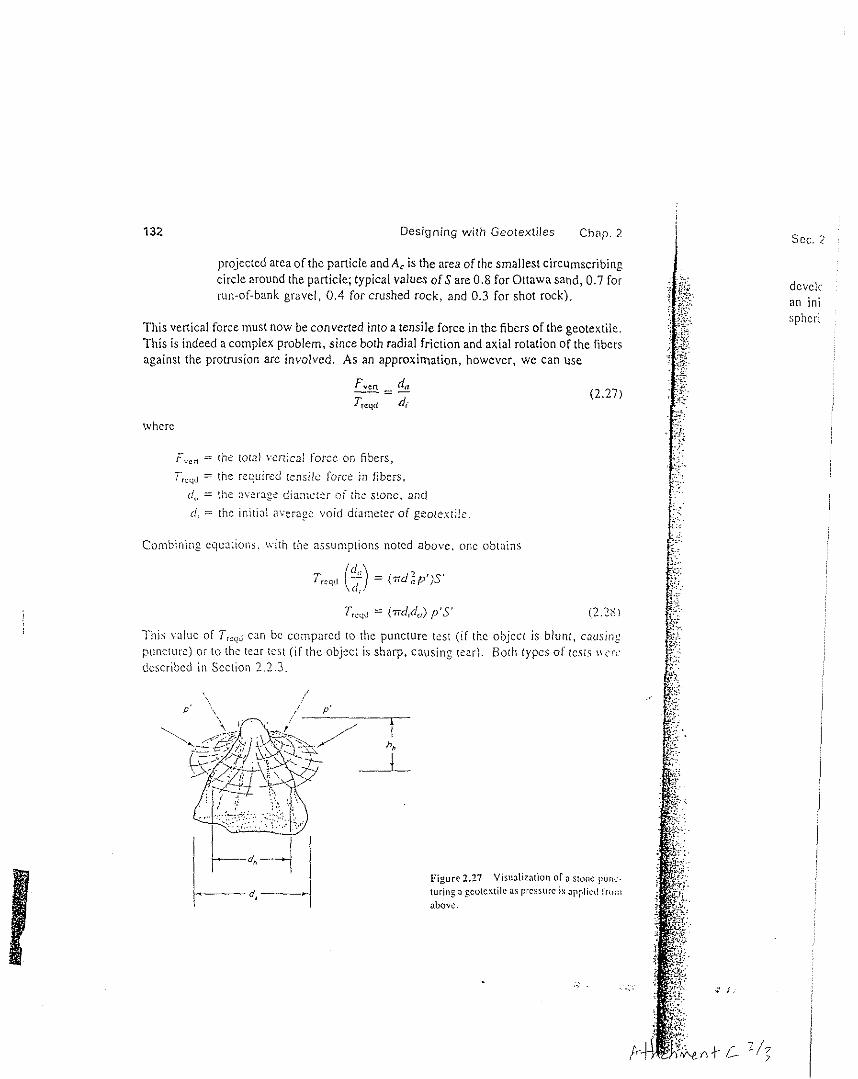
Koerner has developed the following method for evaluating the puncture resistance of a geotextile:
where F,," = the total vertical force imposed on the fibers,
dl, = the average diameter of the hole hh = the propagation height
p' = the pressure exerted on the geotextile, S' = the shape factor, varying from 0 for blunt objects to 1.0 for sharp objects
EVALUATE EQUATION
dh = 2 in (from the 2"x 2" masonry blocks)
hh = 2 in. (from the 2"x 2" masonry blocks)
p3 = 26.0 psi
S' = 0.1 (masonry block is relatively blunt)
Plugging in variables,
Fvm = [(ndh)(hh)~']S" = [(n* 2 in.)(2 in.)(26.0 psi)](O.l) = 32.6 lbs.
... P:IPtUlSDWI'lCm7.enr ProjecrslSC0347 Briramirr E m Grond Ph NiCalcsISC0347~LRPz~nc1~1e~bldg2.doc

Written by: Steve Fitzwilliam Datc: 061311 5 Reviewed by: Gree Corcoran Date: i I YY MM DD YY MM DD
Client: Slough Estates USA Inc Project: Britannia East Grand Ph 11 Project/Proposal No.: SC0347 Task No.: 01
Koerner suggests applying partial factor of safety values to the ultimate puncture strength of the geotextile to account for installation damage, creep, and chemical and biological degradation (Attachment C). Therefore, the following values for geotextiles used in separation, as suggested by Koerner, will be used:
0 Installation Damage 2.0 0 Creep 1.2 r Chemical Degradation 1 .O - Biological Degradation 1 .O
Therefore, the allowable puncture strength of the geotextile (Falo,") as measured by ASTM D4833 is:
Fallow = 32.6 lbs.(2.0)(1.2)(1.0)(1.0) = 78.17 lbs. = 78.0 lbs.
0 CARRIER GEOTEXTILE
The geotextile typically used in this application is Typar type heat bonded nonwoven geotextiles distributed by Linq Industries. Based on Linq geotextile specifications (Attachment D), Typar 3401 will provide a puncture resistance of 41 lbs.
The puncture resistance needed for the carrier geotextile is negligible due to the combined mass per unit area of 12 odyd2 for the two geotextile components of the geocomposite, which is acceptable based on the above calculations for a 2" square blunt object. Since the geocomposite and carrier geotextile will overlie native soil, a maximum particle size will be determined as follows:
Puncture strength of geotextiles = carrier geotextile strength
Puncture strength = 41 Ibs.
Dividing by Koemer's factors of safety described above, Puncture strength = 41 1bs./[(2.0)(1.2)(1.0)(1.0)]
= 17.1 1bs.
Using Koerner's method for evaluating puncture resistance described above,
. . ..: I --:. P:IPRJlSDWPICurrenl ProjeclslSC0347 Britannia Em1 GmndPh I/ICalcslSCO347~LBP~nc1~11e~bldg2,doc -

GEOSYNTEC CONSULTANTS Page 5 of 7
Written by: Steve Fitzwilliam Date: 06/3/15 Reviewed by: Gree Corcoran Date: -1-1- YY MM DD YY MM DD
Client: Slough Estates USA Inc Project: Britannia East Grand Ph 11 ProjectiProposal No.: SC0347 TaskNo.: 01
where F,,,, = the total vertical force imposed on the fibers, d = the average diameter of the particle
P' = the pressure exerted on the geotextile, s' = the shape factor
EVALUATE EQUATION
Fvm = 17.1 lbs, P' = 32.6 psi
s' = 0.75
Plugging in variables,
(assumed for particles in soil)
Therefore, the maximum particle size should be limited to, dm,, = 7/16"
CONCLUSIONS
Assuming the following:
a the construction loads do not exceed 32.6 psi; and a the rebar supports are 2"x 2" masonry blocks, spaced 5 ft. on center
A heat bonded nonwoven carrier geotextile with a puncture strength greater than 41 lbs. will be adequate for protection of the Liquid Boot geomembrane. A nonwoven needle-punched cushion geotextile with a puncture strength greater than 78.0 lbs. will be adequate for protection of the Liquid Boot geomembrane.
- .. ,
P:lPRJSDWPlCarrent ProjecrslSCO347 Britannia Easl Grand Ph NlCalcs~SC0347~LRPirncl1~re~bIdg2.doc

GEOSYNTEC CONSULTANTS Page 6 of 7
Written by: Steve Fitzwilliam Date: 061311 5 Reviewed by: Gree Corcoran Date: 1 I YY MM DU YY MM DD
Client: Sloueh Estates USA Inc Project: Britannia East Grand Ph 11 ProjecVProposal No.: SC0347 Task No.: 01
COMPLETE SET OF GEOTEXTILE PROPERTIES
Typical Typar 3401 heat bonded nonwoven carrier geotextile, when subjected to laboratory testing, should provide the following mechanical property values:
Property Value
puncture strength > 41 1b. grab strength > 130 lb. burst strength > 140 psi trapezoidal tear > 60 1b. ultraviolet strength retention > 70 %
Typical nonwoven needle-punched 10 ozlyd2 cushion geotextile, when subjected to laboratory testing, should provide the following mechanical property values:
Property Value
puncture strength > 78.0 ib grab strength > 250 ib. burst strength > 460 psi trapezoidal tear > 100 1b. ultraviolet strength retention > 70 % - GEOTEXTILE PRODUCTS THAT MEET REQUIREMENTS
The following is a partial list of geotextile products that meet the property values stated above for carrier geotextile:
0 Linq Typar 3401
The following is a partial list of geotextile products that meet the property values stated above for cushion geotextile:
0 Amoco 4510 - Linq275EX 0 Synthetic Industries Geotex 1001 - TC Mirafi 1 1 OON

GEOSYNTEC CONSULTANTS Page 7 of 7
Written by: Steve Fitzwiiliam Date: 06/3/15 Reviewed by: Greg Corcoran Date: 1 I YY MM DD Y Y MM DD
Client: Slough Estates USA Inc Project: Britannia East Grand Ph I1 ProjectiProposal No.: SC0347 TaskNo.: 01
REFERENCES
ACI 318-95 and ACI 318-95R "Building Code Requirements for Structural Concrete and Commentary," American Concrete Institute, Farmington Hills, MI, USA
Koemer, R.M. (1990) "Designing with Geosynthetics", 2" Edition, Prentice Hill, New Jersey.
- -. . .. --Lb, .
P:lPRJSUWPiCswcnl ProjecirlSC0347 Rrilannia Earl Grand Ph NICaicslSC0347_LRPunc1ure~bldg2.doc

PVC PIPE (NOTE 2)
GEOMEMBRANE
SECTION GAS EXTRACTION SYSTEM N.T.S.

ACI BUILDING CODUCOMMENTARY 31 8131 8R-363
APPENDIX E - STEEL REINFORCEMENT INFORMATION
As an aid to users of the ACI Building Code, information on sizes, areas, and weights of various steel reinforcement i s presented.
ASTM STANDARD REINFORCING BARS
ASTM STANDARD PRESTRESSING TENDONS
TYPC' Seven-wircrlimi (Grade 250)
Scvcn-witcsrrant (Grade 270)
Preslrcsring wirc
Preslrcsring b u s (plain)
I'rrsiressing b u r (dclormcd)
Bar S~LC, no.
Nominal diamcrcr, in. 114 (0.250)
5116 (0.313)
318 (0.3751
7116 (0.438)
I R (0.503)
(0.600) 318 (0.3751
7116 (0.438)
I n (0.503)
(0.W) 0.192
0.196
0.250
0.276
314
718
1
1-118
1-114
1-318
518 314
1 1-114 1-318
Nominal area. i n 2
Nominal diamelcr, in.
Nominal wcighr. lblfr

les Chap. 2
(2.24)
ticle size. Thus ~mptions stated the tensile force vs [44]:
(2.25)
:x:.-nle is giv-
C 3-in, maxiniuin iasile stress on the -: (b) the factor of mor of safely fu r :o Equ3tion 2 . IS
:md using tile f d i
Sec. 2.5 Designing for Separation
Figure 2.26 Geottxtilc being suhjecled to tenrite (Gnb) slress as surface pressure is applied and stone hare rends to spread laicr- ally. (a) Actual siiuation. (b) Analogous
(bl grab tension Icsl.
2.5.4 Punc tu re (Tear) Resis tance
Although not only related to the separation function, the geotextile during its placement must survive the installation process. Indeed, fabric survivability is critical i n all types of applications; without it, the best of designs are futile (recall Section 2.2.6.1). In this regard, sharp stones, tree stumps, roots, miscellaneous debris, and other things on the ground beneath the geotextile could puncture through the fabric after stone base and traffic loads are imposed above i t . The d e s i p method suggested for this situation is shown schematically in Figure 2.27. For these conditions, the venical force exerted on the geo- rexlile (which is gradually tightening around the object) is as follows:
where
F,,, = the total venical force imposed on the fibers adjacent to the puncture; dl, = the average diameter of the hole, where dl, (maximum) = do = average
diameter of the aggregate (or stump, etc.); ti, , = the propagation height (=d,); p' = the pressure exened on the geotextile (usually 75% to 100% of tire inflation
pressure at the ground surface); and S' = the shape factor varying from 0 for rounded blunt objects to 1.0 for sharp
angular objects (for aggregate particles, the shape factor can be assumed to be ( I .O - S), where S is the sphericity, from S = AJA,.. where A,, is the

132 Designing with Geotextiles Chap. 2
projected area of the particle and A, is the area of the smallest circumscribing circle around the particle; typical values o f S are 0.8 for Ottawa sand, 0.7 for mn-of-bank gravel, 0.4 for crushed rock, and 0 .3 for shot rock).
This vertical force must now be converted into a tensile force in the fibers of the geotentile. This is indeed a complex problem, since both radial friction and axial rotation of lhc fibers against the protrusion are involved. As an approximation, however, we can use
where
F,,, = the total vertical force on fibers, T,,,J = the required tensile force in fibers,
d,, = the average dianicter of the stone, and (1, = the initial average void diameter of geotextilc
Combining equations. with the assumptions noted above, one obtains
This valuc of Trrc,d can be compared to the puncture test (if the object is blunt, causing puncturc) or to the tear test ( i f the object is sharp, causine tear). Both types 01 tests i w r c described i n Scction 2.2.3
Figure 2.27 Visuaiizalion "fa slonc liunc- tw ine a gcolertile 3s prewrc is applivd l'roiii o b o w
scc . 2
deveic an ini spheri

:iles Chap. 2
is
n' m ng-cm
Sec. 2.3 Allowable Versus Ultimate Geotextile Properties 115
TABLE 2.12 RECOMMENDED PARTIAL FACTOR OF SAFEW VALUES FOR USE IN EQUATION 2.18
Various panial factors of safety
Application area
separation
cushioning
unpaved roads
walls
embankments
bearing capacity
slope stabilization
pavement overlays railroads
Installation Chemical Biological damage Creep' degradation degradation
I . I t o 2 . 5 1.0to1.2 1.0to1.5 1.010 1.2
I . I t 0 2 . 0 1.2to1.5 1.0lo2.0 1.0 to 1.2
1.1 lo 2.0 1.5 to 2.5 1.0 lo 1.5 I .Oto 1.2
1.1 to 2.0 2.0 104.0 1.0 lo 1.5 1.010 1.3
1 . 1 to 2.0 2.0 103.0 1.0 to 1.5 1.0 to 1.3
1.1 102.0 2 .01040 1.010 1.5 1.0 la 1.3
t . l t o 1 . 5 1.5102.0 1.0101.5 1.0 lo 1.3
l . l t 0 1 . 5 l .O t0 l . 2 l.Ol01.5 I . O t 0 1 . 1
1.5 to 3.0 1.0 to 1.5 1.5 to 2.0 I 0 to 1.2
flexible forms l . l t o 1 . 5 1.5to3.0 l.Oto1.5 I .0 to 1 . 1
silt fencer l . l t 0 1 . 5 1.5102.j I.Otol.5 1.0 to 1.1
-The low end of the range refers lo results that hsve been compenr3ied for creep in the perfomancc of the tesls.
T,,,,, = the allowable tensile strength, T,,, = the ultimaie tensile strength,
FSJD = the factor of safety for installation damage.
FSCR = (he factor of safety for creep. FSo = the factor of safety for chemical degradation, and FSnD = the factor of safety for biological degradation. [ <hf 1) '
Note that this equation could just as well have been formulated as fractional multipliers (5 1 .O) and placed in the numerator of the equation. It is placed in this form because other studies have done likewise (e.g., Voskamp and Risseeuw [37]). While the equation indi- cates tensile strength, it can equally weli be applied to burst strength, tear strength, punc- ture strength, seam strength, etc.
For p rob lems dea l i ng tvirhJ4ow through o r wirhin a georexrile, the formulation takes the foliowing form with typical values given in Table 2.13. Note that these values must be tempered with site-specific conditions as was the case with the previous table.

GEOSYNTEC CONSULTANTS Page I of 7
Written by: Steve Fitzwilliam Date: 0613115 Reviewed by: Greg Corcoran Date: I I Y Y MM DD YY MM OD
Client: Sloueh Estates USA Inc Project: Britannia East Grand Ph 11 ProjectiProposal No.: SC0347 Task No.: 01
GEOTEXTILE PUNCTURE PROTECTION OF LIQUID BOOT PARKING STRUCTURE B
OBJECTIVE
At the proposed Britannia East Grand development site in South San Francisco, California, an 80-mil (2.0-mm) Liquid Boot cold spray applied geomembrane gas barrier will be subjected to forces, such as foot traffic, steel reinforcement and poured concrete that may damage the Liquid Boot geomembrane. The Liquid Boot geomembrane will be spray applied to a heat bonded nonwoven carrier geotextile, which will serve to protect the geomembrane from puncture. In addition, a nonwoven needle-punched cushion geotextile will be installed over the geomembrane gas barrier to protect the geomembrane gas barrier from damage during installation of the overlying reinforcement and concrete slab. The objective of this calculation is to evaluate the required puncture strength of both the heat bonded nonwoven carrier geotextile and the nonwoven, needle-punched cushion geotextile.
SUMMARY OF ANALYSIS
The analysis suggests that the puncture strength of the heat bonded nonwoven carrier geotextile be greater than 41 lbs. for Linq 3401. The analysis also suggests that the puncture strength of the nonwoven needle-punched cushion geotextile be greater than 116 ibs. for 10 oz/yd2. A summary of required geotextile properties and a list of geotextile products that meet the material requirements are provided at the end of this calculation package.
SITE CONDITIONS
The components beneath the building are the following, from top to bottom: - 10 inches of concrete; - protection course (a nonwoven needle-punched cushion geotextile); - 80 mil Liquid Boot geomembrane for calculation (minimum thickness
recommended 100-mil) - heat bonded nonwoven carrier geotextile; and
A cross-section of the gas extraction system is presented as Attachment A.
-, . . .., P:IPRllSDWPICunenl ProjeclslSC0347 Brirannia Em1 Grand Ph lllCalcslSCO347_LDPunc1~11e~PSB.doc

GEOSYNTEC CONSULTANTS Page 2 of 7
Written by: Steve Fitzwilliam Date: 06/3/15 Reviewed by: Grep Corcoran Date: / I YY MM DD YY MM DD
Clicnt: Slouch Estates USA Inc Project: Britannia East Grand Ph I1 Projectffroposal No.: SC0347 Task No.: 01
ANALYSIS
0 OVERLYING PRESSURE:
The gas barrier system will be overlain by a nonwoven needle-punched cushion geotextile and a 10 inch concrete floor slab. The maximum loading will be no greater than the loads associated with the construction of the concrete structural slab. The construction loads include foot traffic, steel reinforcement and associated support, and the load of the concrete. This pressure will be exerted directly on the geotextile/geomembrane.
1. Assuming the unit weight of the concrete is 150 pcf, the pressure on the geomembrane due to concrete is assumed to be:
, .................... (150 pcf)(0.833 ft) = 125 psf = 10.868 ................. ps,
2. Steel reinforcement loads are assumed to be a combination of the top and bottom reinforcement, both spaced 12" on center. It is assumed that the reinforcement is supported by a 2"xY masonry support, spaced every 5 ft. Reinforcement will be #6 steel bars, with a nominal diameter of 0.750 in. and a nominal weight of 1.502 1bs.Ift. (Attachment B).
To calculate the weight of reinforcement per square foot in the top rebar, the amount of steel is determined. Four feet of reinforcement is used per square foot, and half of the weight for each bar is attributed per square foot of pressure.
Top: for 1 sq. ft., pressure = 1/2*(4 ft.* 1.502 1bs.lft) = 3.004 lbs. for 5 sq. ft., pressure = 52* 112*(4 ft. * 1.502 1bs.lft) = 75.100 ibs.
?.. ...................
= 75.100 ibs./(2 in.* 2 in.) =!18.8 ,~. . . . . . . . . . . . . . psi;
To calculate the weight of reinforcement per square foot in the bottom rebar, the amount of steel is determined. Two feet of reinforcement is used per square foot.
Bottom: for 1 sq. ft., pressure = 2 ft * 1.502 lbs./ft = 3.004 lbs. For 5 sq. ft., pressure = 52 * 2 ft. * 1.502 1bs.lft = 75.100 lbs.
.................
= 75.100 ibs.l(2 in.* 2in.) = , 11 ............. 8.8 psii !
Total Steel Rebar Pressure = 18.8 + 18.8 = 37.6 psi

GEOSYNTEC CONSULTANTS Pagc 3 of 7
Written by: Steve Fitzwilliam Date: 061311 5 Reviewed by: Gree Corcoran Date: I I YY MM DD YY MM DD
Client: Slough Estates USA Inc Project: Britannia East Grand Ph I1 Projectifroposal No.: SC0347 Task No.: 01
Based on the above calculations, the combined pressure resulting from the concrete and rebar dead weight will be used to design the required cushion geotextiles. The combined pressure is:
(0.868 psi) + (37.6 psi) = 38.5 psi
APPROACH
CUSHION GEOTEXTILE
The cushion geotextile will serve to protect the Liquid Boot geomembrane from puncture by the 2"xY masonry blocks.
Koerner has developed the following method for evaluating the puncture resistance of a geotextile:
where F,,, = the total vertical force imposed on the fibers,
dh = the average diameter of the hole
hh = the propagation height p' = the pressure exerted on the geotextile, S' = the shape factor, varying from 0 for blunt objects to 1.0 for sharp objects
EVALUATE EQUATION
dh = 2 in (from the 2"x 2" masonry blocks)
hh = 2 in. (from the 2"x 2" masonry blocks)
p' = 38.5 psi
S' = 0.1
Plugging in variables,
Fvcrr = [(ndh)(hh)~'IS' = [(n* 2 in.)(2 in.)(38.5 psi)](O.l) = 48.34 lbs.
:<,
P:lPKJlSDWPlCurrenr PropctsISC0347 Britannia Easl Grand Ph IIICalcs~SC0347~LBPunc11~re~~PSB~doc
(masonry block is relatively blunt)

GEOSYNTEC CONSULTANTS Page 4 o f 7
Written by: Steve Fitzwilliam Date: 061311 5 Reviewed by: G r e ~ Corcoran Date: I I YY MM DD YY MM DO
Client: Sloueh Estates IJSA Inc Project: Britannia East Grand Ph I1 ProjecfProposal No.: SC0347 Task No.: 01
Koerner suggests applying partial factor of safety values to the ultimate puncture strength of the geotextile to account for installation damage, creep, and chemical and biological degradation (Attachment C). Therefore, the following values for geotextiles used in separation, as suggested by Koerner, will be used:
0 Installation Damage 2.0 Creep 1.2
0 Chemical Degradation 1 .O Biological Degradation 1 .O
Therefore, the allowable puncture strength of the geotextile (Fa],,) as measured by ASTM D4833 is:
Fattow =48.34 lbs.(2.0)(1.2)(1.0)(1.0) = 116.016 lbs. = 116 Ibs.
0 CARRIER GEOTEXTILE
The geotextile typically used in this application is Typar type heat bonded nonwoven geotextiles distributed by Linq Industries. Based on Linq geotextile specifications (Attachment D), Typar 3401 will provide a puncture resistance of 41 lbs.
The puncture resistance needed for the carrier geotextile is negligible due to the combined mass per unit area of 12 oziyd2 for the two geotextile components of the geocomposite, which is acceptable based on the above calculations for a 2" square blunt object. Since the geocomposite and carrier geotextile will overlie native soil, a maximum particle size will be determined as follows:
Puncture strength of geotextiles = carrier geotextile strength
Puncture strength = 41 lbs.
Dividing by Koemer's factors of safety described above, Puncture strength = 41 1bs./[(2.0)(1.2)(1.0)(1.0)]
= 17.1 Ibs.
. .., P:IPRJiSDWPiCuvenl l'rqleclslSCO347 Brilannia Earl Grand Ph N\Calcs\SC03117_LBPuneIureePSB.doc

GEOSYNTEC CONSULTANTS Page 5 of 7
Written by: Steve Fitzwilliam Date: 0613115 Reviewed by: Grec Corcoran Date: I 1 YY MM DD YY MM DD
Client: Slouzh Estates USA Inc Project: Britannia East Grand Ph II ProjectlProposal No.: SC0347 Task No.: 01
Using Koerner's method for evaluating puncture resistance described above,
Fvcn = [(n)(d2)p'1~' (Attachment C)
where F,,d = the total vertical force imposed on the fibers, d = the average diameter of the particle
p1 = the pressure exerted on the geotextile, s' = the shape factor
EVALUATE EQUATION
Fve, = 17.1 Ibs. p1 = 38.5 psi
s' = 0.75 (assumed for particles in soil)
Plugging in variables,
Therefore, the maximum particle size should be limited to, dm,, = 7/16"
CONCLUSIONS
Assuming the following:
8 the construction loads do not exceed 17.6 psi; and 8 the rebar supports are 2"x 2" masonry blocks, spaced 5 ft. on center.
A heat bonded nonwoven carrier geotextile with a puncture strength greater than 41 lbs. will be adequate for protection of the Liquid Boot geomembrane. A nonwoven needle-punched cushion geotextile with a puncture strength greater than 116 ibs. will be adequate for protection of the Liquid Boot geomembrane.
- I
l - 1 -
P IPRJlSDWPlCurrenl Pro/eclsiSCfl347 Bnlannia Easl Grand Ph IIlCalcsiSCfl347_LBPuncI1~1e~PSR doc -

GEOSYNTEC CONSULTANTS Page 6 of 7
Written by: Steve Fitzwilliam Date: 06/3/15 Rcvicwed by: Gree Corcoran 1)atc: 1 I YY MM DD Y Y MM DD
Client: Slouch Estates USA Inc Project: Britannia East Grand Ph I1 ProjectiProposal No.: SC0347 TaskNo.: 01
a COMPLETE SET OF GEOTEXTILE PROPERTIES
Typical Typar 3401 heat bonded nonwoven carrier geotextile, when subjected to laboratory testing, should provide the following mechanical property values:
Property Value
puncture strength > 41 1b. grab strength > 130 1b. burst strength > 140 psi trapezoidal tear > 60 1b. ultraviolet strength retention > 70 %
Typical nonwoven needle-punched 10 odyd2 cushion geotextile, when subjected to laboratory testing, should provide the following mechanical property values:
Property Value
puncture strength > 116 1b. grab strength > 250 lb. burst strength > 460 psi trapezoidal tear > 100 1b. ultraviolet strength retention > 70 %
a GEOTEXTILE PRODUCTS THAT MEET REQUIREMENTS
The following is a partial list of geotextile products that meet the property values stated above for carrier geotextile:
w Linq Typar 3401
The following is a partial list of geotextile products that meet the property values stated above for cushion geotextile:
Amoco 4510 a Linq 275EX w Synthetic Industries Geotex 1001 a TC Mirafi 1 1 OON -
... P:IPRJISDWPIC~I~~~~~ ProjecfslSC0347 Brirannia E m f Grand Ph IlICalcslSC0347~LBP1~ncIu1e~PSB~doc

GEOSYNTEC CONSULTANTS Page 7 o f 7
Written by: Steve Fitzwilliam Date: 061311 5 Reviewed by: Greg Corcoran Date: I I YY MM DD YY WM DD
Client: Slough Estates USA Inc Project: Britannia East Grand Ph 11 ProjectlProposal No.: SC0347 Task No.: 01
REFERENCES
ACI 3 18-95 and ACI 3 18-95R "Building Code Requirements for Structural Concrete and Commentary," American Concrete Institute, Farmington Hills, MI, USA
Koerner, R.M. (1990) "Designing with Geosynthetics", 2nd Edition, Prentice Mill, New Jersey.
... I P:lPRJlSDWPlCsrre,lr ProjeclslSC0347 Brirmnia Easr Grand Ph IIiCoicslSC0347~LBPunc11~1~~PSB.doc : m-

i PIPE HANGER
r 2" DIA. SCH. 40
SECTION GAS EXTRACTION SYSTEM N.T.S.

ACI BUILDING CODEICOMMENTARY 318/318R-363
APPENDIX E - STEEL REINFORCEMENT INFORMATION
As an aid to users of the ACI Building Code, information on sizes, areas, and weights of various steel reinforcement is presented.
ASTM STANDARD PRESTRESSING TENDONS
ASTM STANDARD REINFORCING BARS
Naminsi d i m c ~ c i , in.
114 (0.250)
5116(0.313)
315 (0.315)
7116 (0.438)
I f 2 (0.503)
(0.MYI) 318 (0.375)
7/16 (0.438)
I Iz (0.503)
( 0 . m ) 0.192
0.196
0.250
0.276
314
118
I
1-118
1-114
1-318
518 314
1
1-114
Bar size, no.
3 4
5 6
7
8
9 10
II
I 4
18
iarninal wight . lblf!
Nominal diarnclcr, in.
0.375
0.5W ,,
0.625
0.750
0.875
1.003
1.128 1.270
1.410
1.693
2.257
Nominal m a . in2 0.11
0.20
0.31
0.44
0.M 0.79
1.W 1.27
1.56
2.25
4.W
Nominal weight, lblfr
0.376
0.668
1.043
1.502 2.044 2.670
3.403
4.303
5.313
7.650
13.600

cle size. Thus nptions stated le tensile force ; 1341:
2.5.4 P u n c t u r e (Tear ) R e s i s t a n c e
Aithoush not only rzlnted ro the separ?:ion function, the geotexlile during its placemen1 milst survive the instnliation process. 1-deed, fabric survivability is critical in all types o f applications; without it, the besl o f &signs are futiie (recail Section 2.2.6.1). In this resnrd, s h x p stones, tree stumps, rooti. miscellaneous debris, and other things on the ground bcnenth the geoti.xtilr could puxture througii the fabric after stone base and traffic loads are imposed above i t . The desizii method suggested for this situation is shoivn sctieninticall~ i n Figure 2 .27 . For thes: conditions, the vertical force exerted on the geo- testiir (whicii is :rsdualiy tightening m u n d the object) is as follows:
F,,, = lhc toral vertical force imposed on the fibers adjacent to the puncture;
d,, = the average diameter of [he hole, where dh (maximum) = d, = average diameter of the qgrega t r (or stump, etc.);
t i t , = the propagation height (=do); P ' = the pressure exerted on the geotextiie (usually 75% to 100% of tire inflation
pressure at the ground surface); and S' = Ihe shape factor varying from 0 for rounded biunt objects to 1.0 for sharp
angular objects (for aggrzgate particles, the shape factor can be assumed to be (1.0 - S), where S ii the sphericity, from S = A,)&., where A , is thi.
132 Designing with Gcotextiles Chap. 2 \ projected area ofthe panicle and A, is the area of the smallest circumscribing circle around the particle; typical values of S are 0.8 for Ottawa Sahd, 0.7 for mii-of-bank gravel. 0.4 for crushed rock, and 0.3 for shot rock).
This vertical force must now be converted into a tensile force in the fibers of the geotextiie. This is indeed a complex problem, since both radial friction and axial rotation of the fibers against the protrusion are involved. As an approximation, however, we can use
where
F,,,, = thc totnl vertical force on fibers, 7;,,,1 = the icuired ens i l t force i n fibers.
= ih.. . ~ i ~ r 3 : c . - d i a n x i r of the stone, and (1; = the initial acerafc void d imcter of geotexriis
Combinin3 equations. i i i t h tile assumptions noted above. onc obtains fjf
Thi5 valuc o l T,,,,J can bc coinpared to the puncture tcst ( i f ihc objcct is blunr. c3~1sin: punciucc) or to the tear test ( i f thc object is sharp. causing war). Boh types of tcsis \~~.r;:
dcscribcd in Section 2 2 . 3 .
I' P' ' ; P .
Figure 2.27 Visudizalion o l j siooe !pun<.
d, ------- t u r i n s o p t c r t i l e as prcssurc is applicil I'rirm
above
..' . .., .
F
3 dcvelc
.,.. an ini sphcri

les C h a p . 2
j
S e c . 2.3 Allowable Versus Ultimate Geotextile Properties
TABLE 2.12 RECOMMENDED PARTIAL FACTOR OF SAFEPl VALUES FOR USE IN EQUATION 2.18
Various pmial factors of safety
Application Insldt~tion Chcrnical Biological arca damage Creep' degradation degradation
separation cushioning unpaved roads walls embankments bearing capacity slope r l ~ b i l i m i o n
pavemcnr arcrlzyr
r~ i t i oad r
flciiblc loms
silt fcnrei
where
T,,,,, = the allowable tensile strength,
TUI, = the itltirnaie tensile strength, FSID = the faclor of safety for instaliation damage, FSo = the factor of safely for creep. FSo = the factor of safety for chemical degradation, and
FSno = the Factor of safety for biological degradation, [.
Note that this equation could just a s well have been formulated as fractional multipliers ( 5 1 .O) and placed in the numerator of the equation. It is placed in this form because other studies have done likewise (e.,o., Vosknmp and Risseeuw [37]). While the equation indi- cates tensile strength, i t c an equally well be applied to burst slrengrh, tear strength, punc- lure strength, seam strength, e lc .
Forprob lems dealing ~v i t / i / i ow r/iro~rg/t or iviihin a geoiexiiie, the formulation takes the following form with typical values given in Table 2.13. Note that these values must be tempered with site-specific conditions as was the case with the previous table.

L I N Q Industrial Fabrics Inc.
I I I T y p x 1111 NP NP I I ? HP 1 H? N? I. D
(NW.P?) ! ! I ! I p r 1401 i W / I? / N? i HP HP ! NP 1 Y( ( D
(NW-PP) 1 ' I I I I
I N P i NP 1 HP i NP 1 HP i NP I S l l . i D