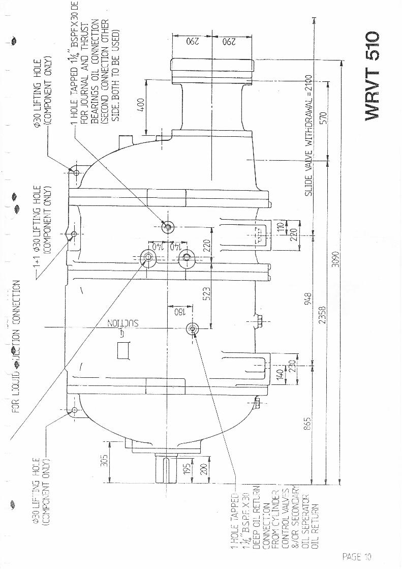
wrvt 510
TRANSCRIPT

$ffiMVEGHMANUALGAS & REFRIGERATION COMPRESSOR
ffi ffi
1
?
G
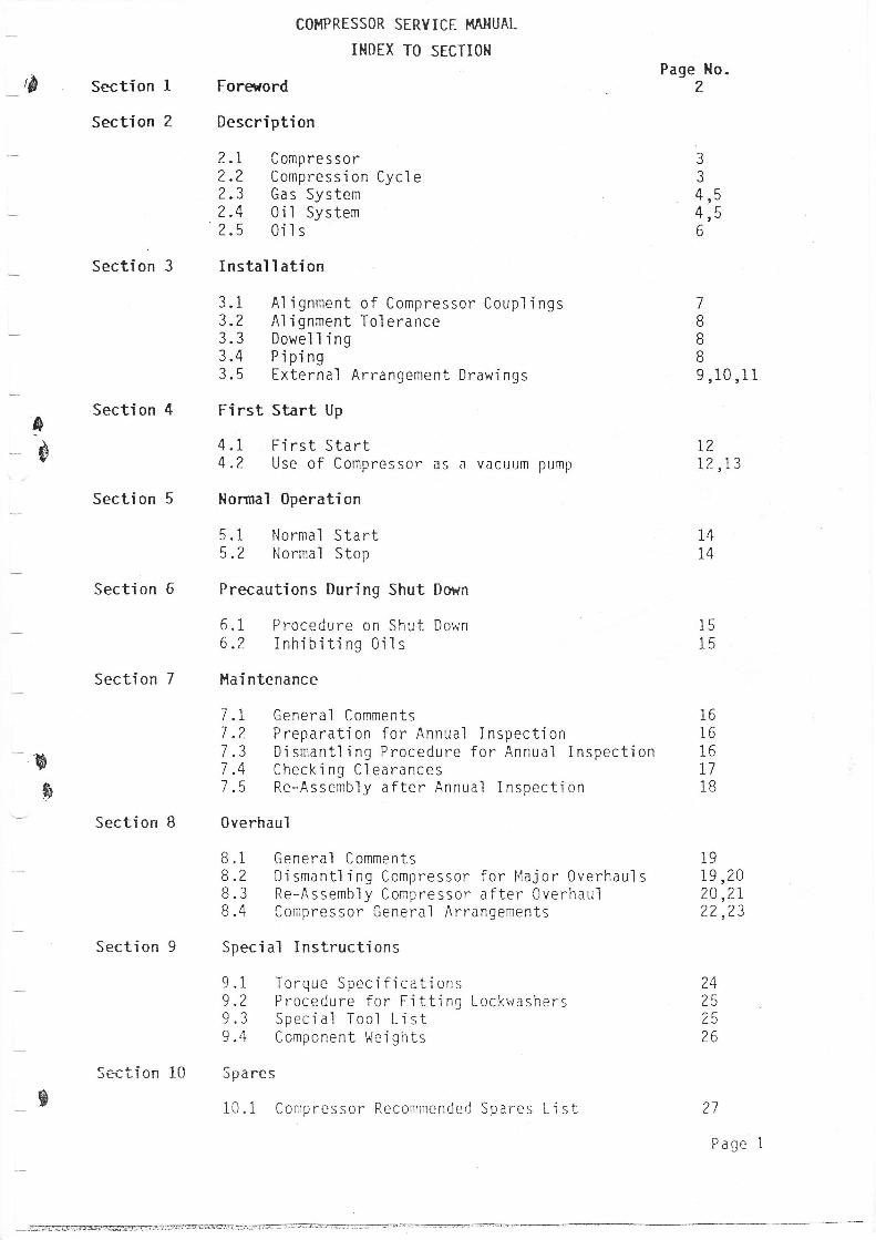
COI.IPRESSOR SERYICE HAHUAL
INDEX TO SECTIOH
Foretrord
Description
2.1 Compressor2.2 Compression Cycle2.3 Gas System?.4 0il System2.5 0ils
Instal I ation
3.1 Ai ignment of Compressor Coupl ings3.2 Alignment Tolerance3.3 Dowe11 ing3.4 Piping3.5 External Arrangement Draw'ings
First Start Up
4.1 First Start4.2 Use of Compressor as a vacuum pump
Hormal 0peration
5.1 Normal Start5.2 Normal Stop
Precautions During Shut Dmrn
6.1 Procedure on Shut Down6.2 Inhibiting 0i1s
i{ai ntenance
7 .l General Comments7 .Z Preparation for Annual Inspection7.3 Djsmantl ing Procedure for Annual Inspection7 .4 Check i ng C1 earances7.5 Re-Assembly after Annual Inspection
0verhaul
8.1 General CommentsB.? Dismantl ing Compressor for l'lajor 0verhauls8.3 Re-Assembly Compressor after 0verhaul8.4 Compressor General Arrangements
Special Instructions
9 .1 Torque Spec i fi cati ons9 .2 P rocedure f or F i tt'i ng Lockrvashers9.3 Special Tool Li st9.4 Component l,Jei ghts
Spares
10.1 Compressor Recommended Spares Li st
Page Ho.2Section
Section
Section 3
Section 4
Section 6
Section 7
Section B
Section 9
c^^+:^- lnJtJl.-LIUII IU
aJ
34q,t-
4 r56
7
IoBg ,10 ,11
I$
L?12,13
Section 5
L/
Page 1
-@l=--rr-ffi:ffi
14T4
1515
B
$
16i616L71B
1919,2020,21?2,?3
Lq
2526
s

-0
a
+
COMPRESSOR SERVICE MANUAL
SECTION 1- FOREWORD
READ CAREFULLY BEFOtrE INSTALLING AND STARTING YOURCOMPRESSOR
These instructions have been prepared to ensure that your compresSor gives lorrgand satisfactory service.The entire manual should be read before reverlrng to any one section for specilrcinf ormationOne copy should be given to the personnel responsible for installing and operatingthe compressor.
All requests for information. services or spares should be directed to:-
HOWDEN CCM PRESSORS LIM ITEDSERVICE DEPARTMENT,133 BARFILLAN DRIVE,G LASGOWG52 1 BE
Telephone Number. 041 -BBZ 3346Telex Number'.778711 - ROCOMP
Ail enquiries should be accompanied by the Howden ContractNumber and the Compressor Serial Number, taken from thenameplate on the side of the compressor body.
ts
s
B
Page 2
a
SECTION 2 - DESCRIPTION
?.1 cot-tPREss0Rs
The Howden 0il injected Screw Compressor is a positive disp'lacement,capacity conirolled, oil flooded rotary machine.
Compression is achieved by the meshing of two hel'ical rotors on para'I1e1shafts housed in a casing.
The accurately mach'ined helical rotors are called Male and Female. Themale (driving) rotor has four lobes which mesh with six flutes in thefemale (driven) rotor, both rotors having the same outside djameter. Eachrotoris supported by two plain white metal thjck walled journal bearingsfitted adjacent to the compression chamber.
As the lubricating or'l is at discharge pressure plus 30 p.s.i Q xg/cnZ)the bearinEs act as shaft seals within the compressor.
Rotor end thrust is accomodated by a balance piston on the male rotor andtilting pad thrust bearings on both male and female rotors.One side of thebal ance pi ston 'is subject to o'i'l pressure (gas outl et pressure pl us 30p.s.i), the other side is at suction pressure and therefore the balancepiston opposes the normal rotor end thrust and assists the thrust bearingloading on the male rotor. The male rotor has lobes of approximate'lycircular arc sections formed helically along the rotor length and thesemesh with corresponding flutes on the female rotor. When the interlobespace aiong the rotor iength is fi11ed, the rotation of the rotors movesthe end of the I obes past the 'i nl et port, so seal 'i ng the i nterl obe space.
As the rotors continue to rotate the intermeshing of the lobes on thedischarge side of the compressor progressively reduces the space occupiedby the gas causing compress'ion. Compression continues until the interlobebecomes exposed to the outlet port in the casing and gas is discharged.See Secti on 2.? -
Capac'ity controi is achieved by means of a slide valve in the casingoperated by a piston in a hydraulic cyf inder mounted on the compressor.
The Piston is actuated by lubricating oi1, fed from the compressorlubricating oi1 manifold, to one or other side of the ptston, moving theslide valve and altering the point jn the rotor length at which compressionbegins. Th'is allows internal gas recirculation, thus controlf ing thecapacity from 100% down to 10% with approximately proportjonate saving inp owe r.
Various methods of hydraulic cy1 inder control are available and theappropriate literature provided by the compressor set supplier, should be
studied before carry'ing out any work on this equipment.
I-$
B
B
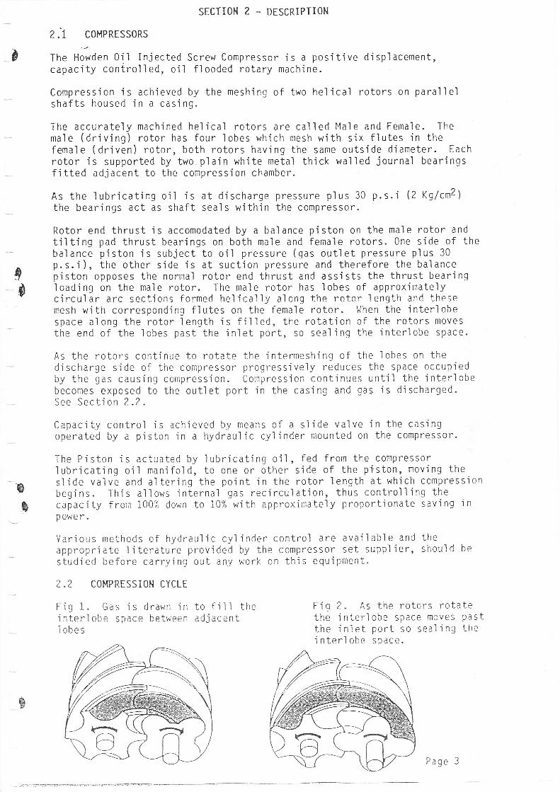
2.2 COI{PRESSIOH CYCLE
Fig 1. Gas js drawn in to fill theinterlobe space between adiacentI obes
Fig 2. As the rotors rotatethe interlobe space moves Pastthe inlet port so sealing thej n ter'l obe space.
.^\
Page 3
uur1r ^LJJUn JLKI ILE- ru\KUf\L
SECTION Z - DESCRIPTIOI{
_t&
I&
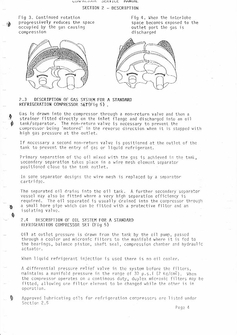
Fig 3. Continued rotationprogressively reduces the spaceoccupied by the gas causingcompression
If necessary a second non-return valtank to prevent the entry of gas or
Primary separation of the oil mjxedsecondary separation takes place inpositioned close to the tank outlet
In some separator designs the wirecartridge.
Fig 4. l.{hen the interl obespace becomes exposed to theoutlet port the gas isdi scharqed
ve is positioned at the outlet of the1 i quid refri gerant.
with the gas is achieved in the tank,a wi re mesh el ement separator
mesh is repl aced by a separator
A further secondary separatorseparation efficiency i s
ined into the compressor througha protective filter and an
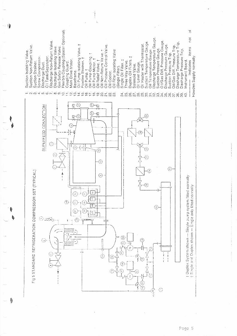
2.3 DESCRIPTION OF GAS SYSTEI'{ FOR A STAI{DARDREFRIGERATI0?{ C0MPRESS0R SET(Fig 5) .
Gas is drawn into the compressor throuqh a non-return valve and then astrainer fitted directly on the inlet flange and discharged into an oiltank/separator. The non-return valve is necessary to prevent thecompressor be'i ng 'motoreC' 'in the reverse d'i rect'ion when i t 'is stopped wi thh'igh gas pressure at the outl et.
&
s
The separated oil drains'into the oil tank.vessel may also be fitted where a very highrequi red. The oil separated i s usual 1y draa small bore pipe which can be fitted withi sol ati ng va1 ve.
0i1 at outlet pressure is drawn from thethrough a cooler and micronic filters tothe bearings, balance piston, shaft seal,actuator.
2.4 DESCRIPTIOH OF OIL SYSTEI'{ FOR A STAHDARDREFRIGERATI0N C0MPRESS0R SET (Fig 5)
tank by the oi1 pump, passedthe manifold where it is fed tocompression chamber and hydraul IC
1.{hen liquid refrigerant iniection is used there is no oil cooler.
A differential pressure relief valve in the system before the filters,majntains a manifold pressure in the range of 30 p.s.i (2 Xg7crTl1. !{henthe compressor operates on a continous duty, duplex micronic filters may befitted, allowing one f ilter e1ement to be changed while the other is inn^^-:+i^-vPcr qLruil-
B Approved I ubrj cati ng oi I s for refri gerati on compressors are I i sted underSection 2'u
oage 4
o
oc
q
Eo.=
oq.)
(g
.9!c
3EoC
.>oo_faC0)
oI
; d c, = ri @ N cd d d; ..i c.i + r; dF d d o i q'l c"i + ri @ * d d ci - a; c"j.q.ri d F cci d or r NC! C{ (\ (\C! C! C{C.tC\ c1 (,)crcrcrcrcocrcocos
a6tro)c6Dtr
tr'ob96.-
o>'o-cCOfoo- -;OJ .CaAC,at,Clr'a6O>.Co;or0Ll9o;x lcU7CaouOO
oa
=(6C.9 q)e: ; -e *33",?ass-: SggF "; -:
es ;.;P ' +d c)
S: b b;?Bs . a* p* iE =^ a F:,iE,i;sE)se.Er€#Eg;ts;i ;E-5ii:t ;':i=tE;F:E;{$AiESE
;;;; Et IIg $ FE f : Ff :: g : f s E Es3 gE : :; gs}
s II s EEE
-0
t-t
$
tal
7oFOUJ
zoOUUJulLLCCLUo-l(D
)Oo-
LFUJaL
oU)(/)LllCEo*
oO
oFccu-lIEu-tllEoc(
o
Far/)
IIL
?
b
\\:-\ Ftr-ll- .-Ei=r:-:,=:,
Page 5
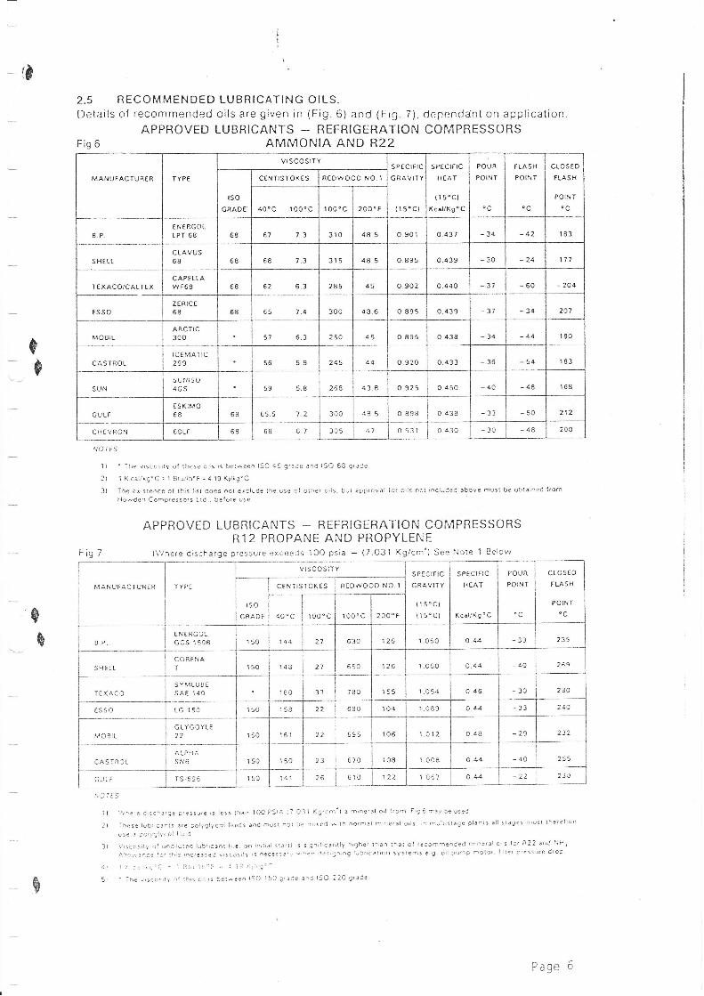
-G2.5 BECOMMENDED LUBRICATING OILS.Details of recommended oils are given in (Fig.6) and (Fig. 7). dependanl on application
APPROVED LUBRICANTS - REFRIGERATION COMPRESSORSFis 6 AMMONIA AND R22
B
$
MATiUIAC IURER | {7E
vrsco srTYs PE CtFrC
GRAVIT Y
( l 5"Cl
s P€crFrc
HEAT
(1 5"Cl(caUKg o C
POUR
POINT
rLASHPOINT
cLos € o
FLASH
PO IIJTrsoGRADE'
CENTISTOKES R€OWO( )o No.l
40"c 100"c ro00c 200" F
B.P€ri E RC OLIPT 68 68 67 t.3 310 48.5 o.901 o.437 - 34 -42 183
S H€LICLAVUS68 68 68 7.3 Jr5 4 8.5 o.895 o.4 39 -30 24 111
rE XACO/C A LT E XCAPELI.AwF68 68 6? 6.3 285 o.902 0.440 -60 204
ES SOZ ERIC E
68 68 65 7.4 300 4 8.6 o.89s o.4 39 34 207
MOBILARCTIC300 63 250 45 o.895 o.438 -34 -44 r90
CASTROLICEMATIC299 56 5.9 245 0.9?0 o 433 -36 -54 183
SUNs uNls{-)4GS 59 5.8 268 4 3.8 o.925 0.450 -40 48 168
CULFESKTTO6B 68 5 5.5 300 .18 5 o a9B o 438 33 212
cH EVRON 6ALF 6g 68 6.7 305 o c31 o 430 -48 200
ll ' The vrscosriy ol lhese olls,s between ISO 46 g'trCe and ISO 6B qrarle
2) 1 Kcal,'tg'C.1 Bru/lb"F.1 I9K,/trg"C
3) The exisleoce ol lhis l;st does not erclude the use ol olher o,ls. bul arO.oval lo( o,ls not included above musl be oblained [.omHowden Compressors Lld . before use
APPROVED LUBRICANTS - REFRIGERATION COMPRESSORSR12 PROPANE AND PROPYLENE
Fig 7 (\/here discharge pressure exceeds 1OO psia - (7.O31 Kg/cm^) See Note 1 Belor^r
MANUFACTURER TYPE
VISCOSiTYs P ECTFTC
GRAVITY
(15.C1
{1 50CI
S P€CIFIC
H EAT
Kcal/(g'C
POUR
POIN T
oc
closEoFLASH
POINTrsoC RAD€
CENIISTOKES REDWOOO NO.1
40. c lo0'c l oo'c 200"F
BPEN€RCOLGCS 1 508 150 144 21 630 126 l 060 o.44 39 235
SilELLC ORE NAI 150 148 650 r26 1.060 o44 40 259
IEXACOSYMLUsEsA€ 1 40 180 7AO 155 1 054 o.4 6 30 2e0
ESSO rG 150 150 158 690 i o.1 1.0a9 o.+4 - 33 240
r,10BlLGLYCOYLE22 r50 161 ?2 695 106 1.012 048 29
CASIROLALPHAsN6 150 150 23 670 104 1 008 0.44 40 255
CULT TS 695 150 26 610 1 067 ?2 230
$
B
rr, r6s
il !r'releds.hareep,eseere,slesrthan lOOFSIA{7Oll (g/cm') amneral o,l {forn F,g6mayLeuse'J
2) ihese tubrlcanl, afe polyqtycol llu,ds aod must 6or be m,rec *,1h no.mal m,riefal o,1s ln meTi,slaGe planl5 !11 slaget musl lhe'elore
u5e a CoiYgltcol liurd
J) V,sccs,ty o{ und,luted lubrrcanl !; e on rn,riat s1a.ti is 5i9^,l,cantly h,ghe, lhao lha! ol .acommeoded m ner.l orlt lo' R22 and NH)
..,.tia--.lece la. !h,s rrcrg3rec v!9ac't\,r: neaalsJ,i *he^ des,g.,ng lrrb:rc;rrcn syster-s a g oil tur.p molor, , lier otessute dloi
at 't 1 .,: ,.1,'a- - ] rJ lL'a .. ,i l! I:,::"4
A 5l ' Ihe v,scos,tv ol lh,5 orl rs bel*e4n ISO 150 gr3'Je 3'd ISO 22O g'ade
B
Page 6
-te
*eA.$'
COMPRESSOR SERVICE MANUAL
SECTION 3 - INSTALLATION
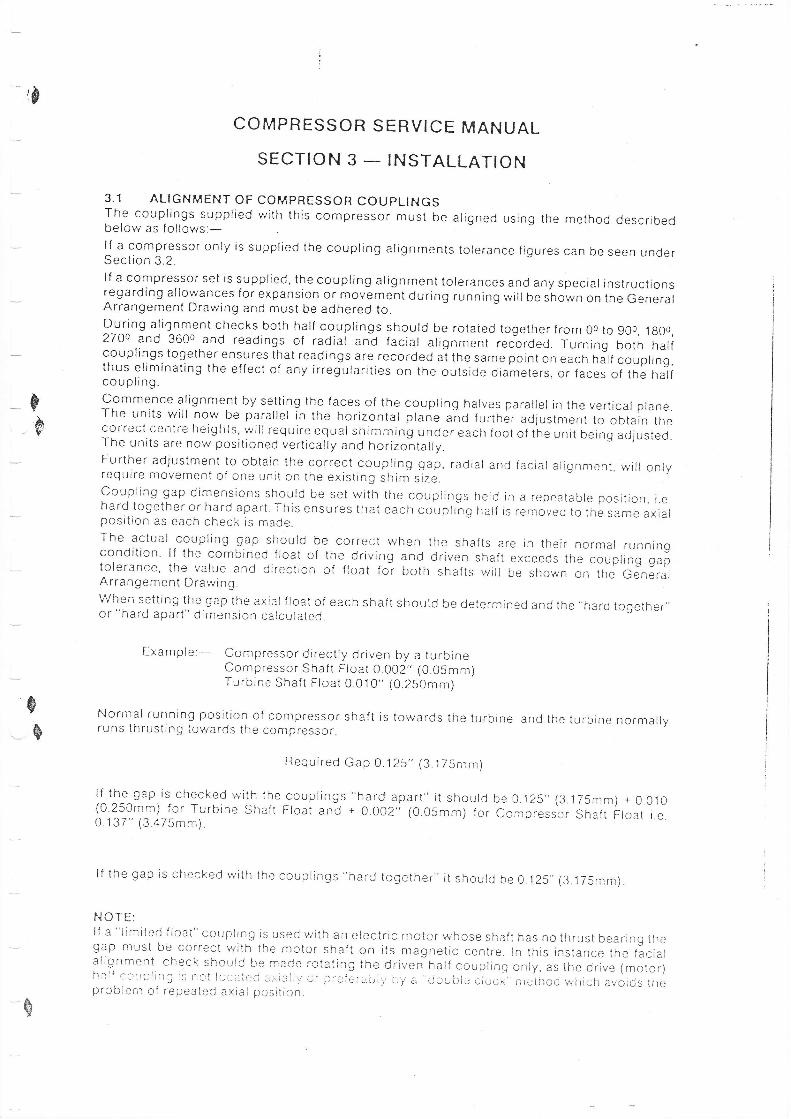
3.1 ALIGNMENT OF COMPRESSOR COUPLINGSThe couplings supplied vrith this compressor must be aligned using the method describedbelow as follows:-lf a compressor only is supplied the coupling alignments tolerance ligures can be seen underSection 3.2.lf a compressor set is supplied, the coupling alignment tolerances and any special instructionsregarding allowances for expansion or movement during running will be sio*n on the GeneralArrangement Drawing and must be adhered to.During aliinment checks both half couplings should be rotaied together from 0o to 900, lg0o,27oo aad 3600 and readings of radial and facial alignment recorded. Turning both halfcouplings together ensures that readings are recorded at the same point on each hJlf coupling,thus eliminating the effect of any irregularities on the outside diameters. or faces of the halfcoupling.Commence alignment by setting the faces of the coupling halves parallel in the vertical plane.The units will nov; be parallel in the horizontal ptane a"no further adjustment to obtain thecorrect centre heights, will require equal si-rinrrning under each foot of tie unit being adlusted.The units are now positioned vertically and horizontally.Further adjustment to obtain the correct coupting gap, radial and facial alignment, will onlyrequire movement of one unit on the existing shim slze.Coupling gap dimensions should be set with the couplings held in a repeatable position, i.ehard together or hard apart. This ensures that each coupli"ng half is removed to the same axialposition as each check is made.The actual coupling gap should be correct whencondition lf the combined float of the driving andtolerance, the value and direction of float to? Ootn
the shafts are in their normal runningdriven shaft exceeds the coupling gapshafts will be shown on the General
eq
Arrangement DrawingWhen setting the gap the axial f Ioat of eachor "hard apart" dimension calculated
shaft shoutd be determined and the,.hard toEether,,
Example:- Compressor directly driven by a turbineCompressor Shaft Ftoat 0.002" (0.05mm)Turbine Shaft Float 0.010" (0.250mm)
Normal running posrtion of compressor shaf i is towards the turbineruns thrusting tovrards the compressor.
and the turbine normally
Bequired Gap 0.125" (3.175mm)
if the gap is checked with the couplings "hard apart" it should be 0.i25,,(3.175mm) + 0.010(0.250mm) for Turbine shaft Float and + 0.002'; (0.05mm) for Compressor Shaft Float i e.0 137" (3.475mm).
lf the gap is checked rvith the couplings "hard together" it should be 0.125"'(3.175mm).
NOTE:lf a "limited f Ioat" coupling is used w'ith an electric motor whose shaft has no thrust bearing thegap must be correct rvith the rnotor shaft on its magnetic centre ln this instance the faclalalignment check should be mace rotating the,ii-lverihaif coupiing oniy, as ihe orive (motor)hrlf e clrplin3 i: ncl lccatecj :xialiy oi pi-ufcri.Li';, Ly a "cioublc cioox'nretirocj which avorc.Js tireproblem of repeated axial position"
$
rltI
{6
p
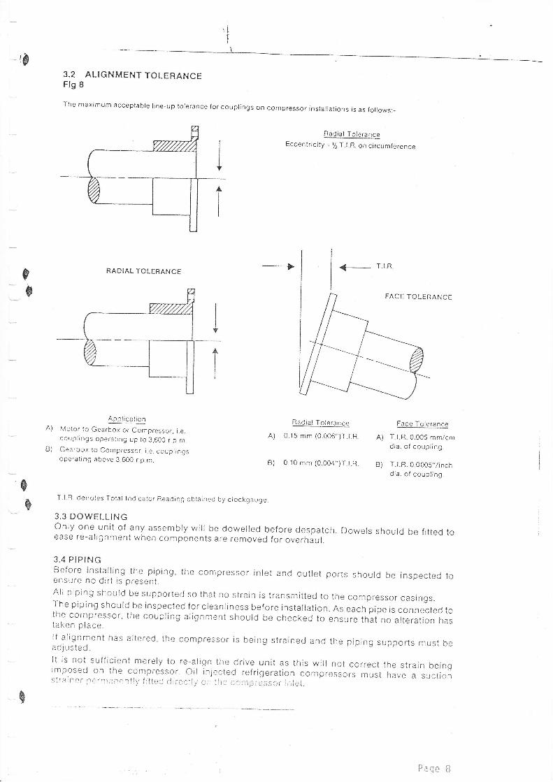
3.2 ALIGNMENTTOLERANCEFlg 8
The maximum acceptable lrne-up tolerance for couplings on compressor installations is as follows:_
Radial ToleranceEccentncity = !/. T l.R. on circumference
A)A)
B)
Is
RADIAL TOLERANCE
ApplicaticnMotor to Gearbox or Compressor, i.e.couplings operating up to 3,6O0 r.p m.
Gearbox to Compressor, i.e. couplingsoperating above 3,600 r.p.m.
----'
Radial Toierance
0.15 mm (0.00,6")T l R
B) 0.10 mm (0.0O4")T.t R B)
Face Tolerance
T.l.R. 0.005 mm/cmdia. of coupling.
T.l.R. 0.0005"/inchdia. of coupling.
-B
T.l.R. denotes Total lndicator Reading oblained by clockgauqe.
3.3 DOV/ELLINGOnly one unit of any assembly vrill be dowelled before despatch. Dowels should be fitted toease re-alignment when components are removed for overhaul.
3.4 PIPINGBefore installing the piping, the compressor inlet and outlet ports should be inspected toe nsure no did is present.AII plping should be supported so lhai no strain is transmitted to the compressor casings.The piping should be inspected for cleanliness before installation. As each pipe is connected tothe cornpressor, the coupling alignment should be checked to ensure that no alteration hastaken place.lf alignment has altered, the compressor is being strained and the piping supports must bea dju sted.It is not sufficient merely to re-align the drive unit as this will not correct the strain beingimposed on the compressor. oii injected i'efrigeration compi'essors inusi have a suctionsirainer lternianrntlr,, f lttcC direcil.,,cr-- iitc ccirpre ssoi- iriiei.
FACE TOLER
Paqe B
BE6'SE000'9€
O4
\oLnrrlr
o-tO
3ormtsE,
=
X*"7
OHF(JIr Ia
-'L-lJL:]t9
=gz.4dOIIo_V)mr-
OO!e
O(\\og3r[-LJ IHl>lz-l1lo_l
c]I' I
E.=F
-OZ- ttt IB+=lc) tl -J-<LLa-2.r,4O=d u-,r a^O-oHo-t?n=r\- -7 rn(/)OE
.I
::)dIr I
aLl.J
I
C)Ir.Or
t5z.Flr:id.OaaLN t,JUJAGCfo- o-5-cC) -JLJ O.
llo_,-a&YtrtQzO:q ,H.-95
L t.l
^d_+Li22O_!JOO_ ILJ4CY- Iro=LLOtA^lltr --l--\lrllrl:t< t--l r n
" c\7
-X<
6L!L3t:lJg;7.
dC]tto_tftEA
- *+--r) i -
P{GE 9
-{&
0I
CYC)u_alr I:faIO9€
sR
-B
otol..-
tr
=
r(\il
J4
d.O:trF
=L!
LL.JOO
*aEF^o-lF-Cl8=Ei,H
="F 42.=L L^
-\-ooF=tr-t_4"UEAnir=P*<oE=4,2-tntJFL- rr l.-r C)
-3=g'a.J ---'r d a- uJ(J-<ffo
=HHHA
.z.oFz.lr I
z.E)(lzC)TJ
Ir II
O=t3Z.Flr)Orn-g
-e
.Z.OFZ-Ir I
z.Oo_:OLJ
lr II
OIL:]L
Flr:Ocn'g+
r
e-s
Z--O,H,F,IJ
ll I
Z,Z.tc)
]LJl
Z,C)
A.r?1J
-s''-Lf)a
I
=;r-\ J-l' .z-.--Ot-f i-:/-=-rl-, z-q =Eofrrl o8LJ
d.OLt*
.J (r'a5LtzL9&qLrJ L! rJ-*[x.Lntr(frr> ==od OO
c:: 91,,
_8 s__,
e=sf-\- |
H'-, PZ.ZT_Z.A Z.OO' C)LJII LJ
iz.,-" <, CrLu r' I f1o-XLro_ ,,. c..-{il-5ilP?\*Hr
-O
rrlo1El s
PA6F lC}

tj]=Jo_
Z.
B
c
i
Z-
O,-L-
-Lr)T
?noXriN-= s-<Lo:_aij. ()-o=J<-<r--)C,O=Lr-l U-t fr]o_ff4aEE*.
::? :lts(JL-1-
L./-\co!"S
L:]f
I
o_z.ao(O
Z.O
EH3=z.YtrO-7L-f
$coi<-9=HH<d-6e+=quJ .r'{+ @.o cl,l Z. cv Lr-i
^ ";F5H? Exla$ EsF=
3n+=lr (\Ftrl
ll'CLf,
LA 9.c(! ,-=-r& IrrT.'C: F
)- fJ-
<-- LflLll.7
HsE? t-r_ t__r
- O- rr-NEHJUZ
?,n If* c!'>-+ >( L-.,
OOCNax.
I' I
I^I oill
u)z. :)C)
Vl l._{ IrtL:t l-- coUh !_uoaY 1. 1_.-,<t z_u)2. C) =ca="5,F--llf
-r_J=:wu'i !-r.l :-
a+HsILJtA,^F (J Y-t u'
(:l1
I
Z.trfqCYC)t,Ilr I
LIIi:lOrn
q-(JoiOo.
LL.Oi'Vicd
-J\-OIr I
o_o_
I !-JI
C)I&,
ls
,lguvillsi0l1-
PA6t 1i
I
COI'IPRESSOR SERYICE I{AHUAL
SECTIOH 4 - FIRST START UP
4.1 FIRST START
Installation of the compressor w'ill have been carried out in accordancewith Section 3 of this manual however the commissioning engineer shouldascertajn that the correct procedures have been fol'tow6O, in particular thecgupling ai ignment must be checked, then proceed as fol lows:-'1) Disconnect the coupling between the dri've anC the compressor and checkthat the direction of rotation is correct to drive thf compressor in a
clockwise direction looking on to the compressor input snait.2) Fill the oil tank with lubiicating oil of the correct grade to therequired level as indicated on the tank level sight 91iss.3) Ensure that the manifold and oil pipes to the compressor are clean thenstart the lubricating oi1 pump motor to circulate the ojl and clean thesystem.
4) The lubricating oi1 pressure differential relief valve should be set togive a 30 p.s.i Q Kg/cnz) oil manifold differential pressure at. correct operating temperature, with clean oil filter elements fitted.5) Check the operation of the safety trips by running the drive unit dis-
connected from the compressor and mechanicaliy operating the trips,check that the actual settings are in accordance with the contractspecification. The lubrica!ing oil differential pressure trip can beset at 12 p.s.i (0.85 Kg/cn?) 5y partiatiy-ctosing rhe oit fitteroutlet isolation valve and thereby reducinq the differential oi'lpressure. As the filters become dirty the differential ojl pressureyjll drop to these figures which are the minimum accepted vaiue.6) Check that the compreisor turns freely and reconnect the couplingbetween the drive unit and the compressor.
7) Check that the cooling water is turned on to the lubricating oi1 coo'ler,r'f f i tted.B) check that ali gas inlet and ouilet isolating valves are open.9) Start the Iubricating oii pump motor.
N0TE: The conipressor should be unrcaded prior to start up. If thecompressor is started without first being unloaded a higher startingtorque wi
.l 'l be requi red.i0) Start the drive unit and check that al1 gauges are indicating correctly.11) Run the compressor for 30 minutes at minimum gas flows and check thatall readings are normal, then operate the capacity contro'l valve to the
required positjon, this position will be indicated on the dial mountedon the hydraulic cylinder. if possible check the slide valve controlover the full ranqe of capacity.
4.2 USING THE COI"IPRESSOR AS A YACUUII AIR PU}IP IH A REFRIGERATION SYSTEFI
Jf n9 vacuurTl pump is available to evacuate the plant prior to charging withRef rigerant, the compressor may be used for th.i_s purpose.Close an isolating valve downstream of the compressor ojl tank and arransea vent at the hiqhest point available, situated between the oj'l tank andi sol ati ng va1 ve.
l.It'th the suctjon isolating valve open, start the compress0r, air will bedrawn from the plant and djscharged through the vent thus evacuating thep1ant. Under these condit'ions some oil vapour carry over may be seen inthe discharged a'ir. Initialiy the compressor discharge presiure wili bef ai r'ly hl gh but thi s wi I I drop as the pl ant i s evacuated.
,6-f-I
ce
€
s
q Page l2
l
i0 COI'IPRESSOR SERYICE I.IAHUAL
SECTION 4 - FIRST START UP
When the plant is evacuated close the suction valve and stop the compressorinrnediately the valve is closed. The vent valve .un no*-ue-cioseo.
The plant is now evacuated but the compressor jtself contains air atatmospheric pressure. This can be removed as follows:-
0pen the val ve on the vent 'l i ne -through which a j r was di scharged. Af terthe plant has been charged with Refrigerant open the suction isolat.ingvalve a small amount allowing Refrigeiant into the .o*p..rro. ,utdisplac_ing the remaining air. When-Refrigerant starts to pass through thevent, close the vent line valve. The comfressor set'is now charged withRefrigerant with the minimum quantity of irapped air.
HOTE
06
If a suction low pressure trjp is fitted itthis switch to allow the compressor suction
e6
may be necessary to disconnectpressure to fal I .
&
Page 13
-re
I;-6
€
_s
\ltt
\
COMPRESSOR SERVICE MANUALSECTION 5 - NORMAL OPERATION
5.1 NORIITAL START1) Check the level of the oil in the tank.2) check that ari necessary gas, oir and water varves are open.3) Start the lubricating oil pump motor.4) Ensure the capacity contror varve is in the fuily unroaded position.5) Start the drive unit and check that all gauges ire indicating normal readings.
5.2 NORMAL STOP1) Stop the drive unit.2) After the compressor stops, the control system should be operated to move the slidevalve into the off load position unless the control system does this automatically.3) After the compressor stops rotating, stop the lubriiating oir pump motoi.
-
!) Close all gas and water isolating valves.The compressor is then ready for start up sequence.
NOTEA log should be kept of the instrument readings so that deviations from correct runningconditions can be readily observecJ by the *nglnee, in charge ot the installation.
Page 14
ii COIIPRESSOR SERVICE I,IAI{UAL
SECTION 6 _ PRECAUTIONS DURIXG SHUTDOI.{N
PROCEDURES ON SHUT DOI{I{
The Howden 0il Iniected Screw Compressor cperates on an oil/gas mixture andshort periods of shut down will not adversely affect the compressor. ifthe compressor is shut down for an extended period the lubricating oi1 pumpshoul d be operated for approximately ten mi nutes week'ly, to di strr'bute oi Ithroughout the set.
1f the shut down period is three months or more the above procedure can berepeated at weekly intervals, but the compressor set should also run forone hour each three months, a'lternatively the normal lubricating oil can bedrained off, replaced with inhibiting oi1, and the set run for one hour.If the compressor has been run on inhibiting oi1 thjs should be repeated atthree month'ly intervals during the shut down period. Approved oils areshown in Section 6.2.
HOTE
1) Before putting the compressor set into normal operation, the inhibitingoil must be removed and the system filled wjth normal oil.
?) During shut down period'in cold conditions any water cooled items ofplant should be drained, or the cooling water flow majntained toprevent damage due to freezing.
6 .2 IHHIBITI}IG OiLS APPROYED FOR USE h{iTH HOHDEH SCREH COI,{PRESSORS
The following is a list of approved inhib'iting oils suitable for use on theHowden Screw Compressor pricr to a lengthly period of shut down.
Shell Ensis 10Esso lL 1175ttobil - Armo 524Caltex Preservation 0il 10H
6.1
0
6
eq
&
I
E
9
€
7.1
COI'IPRESSOR SERYICE I{ANUAL
SECTIOH 7 - I,{AI}TTENANCE
GE}IERAL COI'I'IE}ITS
The component parts of this compressor are large and heavy and considerabledif f icul ty w'i11 be encountered 'if maintenance/overhaul is attempted w'ithoutthe use of a manipulator frame
The compressor is designed to give long periods of trouble-free operationwith the minimum of maintenance, however, an annual inspect'ion jsreconmended to check if there is any significant wear on thrust bearings,slide valve guide block or PTFE seals. Should wear be found thesecomponents must be rePi aced.
Refer to the sectional arrangement drawings supplied. All fasteners shouldbe torqued to the specified value as stated in Sect'ion 9.1 usingappropriate torque wrenches. All lockwashers, tabwashers, 0 R'ings and PTFE
seals must be renewed on assemblY.
Sectjon 9.2 describes I ockwasher assembly procedure. Special tool s tofaci I'i tate di smantl i ng and assembly can be provi ded. These are I i stedunder Section 9.3. Detai.l s can be provided on request.
Sectjon 10 detajls part numbers of normal'ly replaceable components.
7.2 PREPARATION FOR AHNUAL INSPECTIOH
Before doing any work on the compressor the following precautions should be
taken.
. Isolate the drive unit. DepressLtrise and purge the system.
. Djsconnect the drive couPl ing.
. Pl ace a receptacl e under the outl et end of the compressor to catch any
o'il which may drip when the hydraulic cylinder or the outlet end coverare removed. (A dra'in pluq is fjtted on the underside of the inlet and
outlet casing to facjl itate oil drainage).4. Insure all I ifting tackle in good condition.
7 .3 DISI'TANTLITIG PROCEDURE FOR ANNUAL IHSPECTION
Commence at djscharge end wjth hydraulic actuator. Extract the 4 off cap
screws holdjng the a'luminium cover to the cylinder Cover and remove"
Extract the 15 off cap screws securing the cylinder cover to the hydraul iccylinder and remove the cover complete with limit switches and thei"ndicator spindle which are attached to it. The cylinder c0ver weighsI 20K9.
I'lo te : - The indicator spindle has to clear a guide block whjch moves alonga spiral groove in the spindle. care must be taken to avo'iddamage to either spindle or gu'ide curing either removal 0rassembly. Mark the spi nd1 e to ensure correct assembly -
1
?
3
Page 16
COI"TPRESSOR SERYICE I,{AI{UAL
SECTION 7 _ I'TAINTENANCE
Remove the actuator stop sleeve,'if fjtted, from the cylinder bore.iii tfr. piston withdrawal gear listed under Section 9.3 and pu11 the sl idevalve assembly until the piston locknut js clear of the cyljnder.Untoct the pi!ton lockwasher and locknut and remove. i.lithdraw the pistonfrom the cyf inder. The piston weighs 50 Kg'push the piston rod and slide valve towards the inlet to the limit of itstravel .
Support the weight of the actuator cylinder. The actuator cyf inder weighs
S0b' f g so a crane or chai n bl ock wi I I be requi red '
Extract the 16 bol ts and spri ng washers securi ng the cy'l 'inder and usi ng thejacking holes provided in the flange, iack out the cylinder.
REITOYIHG THE OUTLET EHD COYER
Extract most of the set pins securing the outlet end cover.
Fit a shackle to the liftjng eye on the top of the cover and support coverwith a sI ing. The outlet end cover weighs 900 Kg'
ng the cover to the outlet end casing,and remove the cover. Take care not to
l,l.ith the out'let cover removed the sl ide valve can be drawn to a pos'itionwhere i t j s sti l'l supported by the val ve gu'ide, to a1l ow sl i ngi ng ' The
slide valve and piston rod weigh 400 Kg. Support the valve by means of a
sf ing and puiI clear.
The compressor has now been dismantled enough to allow inspection' By
shin.ing a torch from the valve bore, a visuai inspection of the rotors can
be ach'ieved.
New 0 Rings and PTFE seals shou'ld be fjtted prior to re-assembly on thepiston and piston rod guide in the cylinders'
7.4 CHECKIHG CLEARAHCES
Knock out the dowel Pins locatiextract the rema'ini ng set Pi ns
damage the piston rod.
REI.iOVI}IG THE SLIDE YALYE
GUlDT BLOCK
The gui de bl ock 'l ocateswi dth of the gu'ide bl ockShould the dimension fal
the sl'irle val ve and shoul d be checked for wear' The
shou'ld be within the I jmits 49.991/49.965 mm'
I outside these I imj ts i t must be repl aced.
THRUST BEARiNG FLOAT
I\,1ount a dia'l test indicator to a su'itable point on the casing with the
ipi.afe touch'ing the end of the male rotor. Using a suitab'le eyebolt (t'124)
in tne tapped h6le of the inlet shaft pull the rotor hard to inlet. Th'is
will ..qrire some form of tackle since the male rotor weighs 1200 Kg" Set
the dial test jndicator to zero and puslr the rotor hard to outlet and
l.ecorri Liie r.ead rrig. Tir is rcriii iirg i s iltc rtal c l"otci' fl cat arC shoul d be
w1thin the range 0.450/0-35mm page 17

,
-e
COHPRESSOR SERYICE }'IA}IUAL
SECTION 7 _ T.IAIHTEHAI{CE
Repeat this procedure for the female rotor. To do thjs the female rotorcover, R51132, weighing 55 Kg will have to be removed.
Should the rotor float be greater than 0.450 nm the thrust assemb'ly shouldbe dismantled and the other bearjngs checked for wear. In this caseproceed as for maior overhaul, see Sectjon 8.
7 .5 REASSEI'{BLY AFTER AHHUAL I}.ISPECTIOH
Ensure the gu'ide block is in posit'ion on the slide valve bore. Lift theslide valve into position and push it all the way home. Take care tosupport the slide valve unt'il a'll its weight is taken by the guide.
Lift the outlet end cover, with a new 0 Ring, into position and locate withdowel pins. Take care not to damage piston rod. Secure with set pins.
Fit a new 0 ring and PTFE sleeve in the piston rod guide on the actuatorcylinder. Fit two new 0 rings'into their recesses on the cylinder body.rlt two lengths of screwed rod (M24) into opposite holes in the outlet end
cover. The rods must be at least 350 mm 1ong. Lift the cyl"inder overthese rods and locate in pos'ition. The rods w'ill act as gu'ides.
I'lB: 0n no account al I ow the screwed rods to support the wei ght of thecy1 i nder.
Fit suitable washers and nuts to the rods and pu11 the cyf inder home,
securj ng wi th set pi ns.
pull the piston rod out until ihe end is clear of the cylinder. Re-fit thepiston to the piston rod and secure with new locknut and lockwasher.
Re-fit the actuator stoP.
Careful1y f ift the cy1inder c0ver into position conrplete with actuatorspindle making sure the guide fits jnto the correct spira'l gro0ve whjch has
been marked pieviously. Secure with cap screws and re-fit cover assemb'ly"$
s
I
Page iB

CCfiPRESSOR SERYICE Ii{ANUAL
SECTION B _ OYERHAUL
--*
8.1 GE}IERAL COI''T{EHTS
Although a yearly inspection is reconrmended it is essential that a major
overhau'l is- carried out when approxjmately 4 years operation has been
reached.
Should bearing wear be excessive before this then a major overhaul will be
iequired earlier. To carry out a major overhaul the compressor will have
to be removed from the bed to a cl ean workpl ace and mounted on a
manipul ator frame.
8.2 DISI'{ANTLIHG PROCEDURE
The compressor is first to be dismantled as for annual inspection under
sections 7.2 and 7.3.
REI'IOYIHG THE IHPUT SHAFT SEAL
After the driven half coupling and key have been removed, extract the cap
screws from the shaft end'cover and using the iacking holes provided and
ihe "T" bar iacking tools remove the shaft cover. (80 Kg)
Follow th'is by removjng the seal jng washer and the statjonary seat- Aga'in
,;i;; tt e ;t"" iacking iool s withdriw the seal housing. Pul'I._out the shaftieal
-tak'ing caie not to damage the carbon face- Usjng the "l': ^iacking.tools withdraw the balance piston and balance p'iston sleeve (if fitted)from the inlet end casing. (Ba1ance piston 20 Kg)
INSPECTION OF THRUST BEARI}IG ASSEI{BLY
Release the locking plates on the rotor shaft end p1ate, remove the threebolts and the shafi end plate. Remove the B hex screws from the reversethrust p'late and remove comp'l ete w j th f I oati ng seal and seal retai ni ng
p1ate. Remove the adiust'ing packers. Extract the reverse thrust bearings'
itn. tf,.rst bearr'ngs wei gh 50 Kg) '
Draw the thrust collar from the shaft and remove the key. Remove the 8 hex
screws and lift out the thrust hous'ing with the main thrust bearing. (The
irous'ing and bearing compl ete we j ghs 200 Kg) '
Visually inspect the thrust pads for damage or wear, if they are not being
,.un.*edthey should be cleaned'in solvent, then dipped in clean oil and
wrapped in greaseproof paper or clean cloth until re-assembly takes place.
RET,IOYII{G IHLET END CASING
Fit a shackle at the top of the inlet casing" Knock out the dowel pins
locatjng the casing to the main casing. Support the weight w]th the crane'Remove the 44 set Iins from the inlet casing and careful'ly slide the casingover the extended shaft of the male rotor taking the 0 ring seal w'ith it"The jnlet casr'ng weighs 1053 Kg.
A?
I
D:ao I OruJr. +-
LUTTITKL))UK )LKI ILL TU\NUAL
SECTIOH 8 - OVERHAUL
RE}TOVAL OF ROTORS
l.li th the 'inl et casing and thrust assembl ies removed and the compressorsecurely fastened to the manipulator frame rotate the compressor tjll the.inlet ena is uppermost. Screw an eyebo'lt into the end of the male rotorand lift clear'of the casing slow'ly turning it clockwise to ease the rotorform past the female. The rotors weigh 1 tonne each.
Repeat for the female rotor.
rotors by the.ir iournals on soft (preferably wooden) vee
allow rotors to rest on their tip seals-
outlet end journal bearings are held in position by setthese removed the bearjngs can be pressed out using theI isted in Section 9.3.
Always supportbl ock s. Never
The i nl et andscrews. Hi thspec i a1 tool s
Turn the compressor back hcrjzontal and, having smeared the bearing bores
w.ith oi'l carbf ul 1y f i t the i nl et casi ng wi th a new 0 ri ng over the rotors .
Locate the inlet iasing in position with dowel pins, fit the bolts and
secure them. (see torque specjfication in Section 9).
ASSEMBLY OF THRUST BEARIHGS
T Fi t thrust housi ng wr'th adjusti ng washers to the outl et end casi ng. Fl't
; main thrust beariig, thrusi collar w"ith key and rotor end piate. Torque
thrust housing bolts to required setting'
Check the journal bearing clearances are within the tolerances 0.28/0.34mm.if outw'ith th'is speciticitton fit new bearings in preparation for re-assembly.
The iournal bearings weigh 100 Kg each'
8.3 RE-ASSE}'{BLY AFTER OVERHAUL
Smear the outlet end bearing bores w'ith lubricat'ing oil and turn the
compressor body vertical w'ith the j nl et end upperrnost.
Carefully lift in the female rotor. Carefully lift in the male turninganti-clolt*ise to allow the rotors to mesh. Ensure the rotor lobes mesh atthe seri a'l numbers.
push the rotor hard to outl et and mount a di al i ndi cator' at a conven'ient
place with the spindle horizontal and the dial set to zero.
push the rotor hard to inlet until the thrust collar comes up hard againstthe pads and note the reading. Thjs reading is the 0UTLET END, HARD T0
INLEi CLEARANCT and should be 0.650/0.600 mm. To obtain the correctclearance shims should be added or packers ground as required. Finalreadjnqs must be taken with housing bolts and rotor plate bolts torqued iothe requj red setti ngs.
Fit the reverse thrust bearing and p'1ate with adiusting washers. Leave the
bolts slackened back. Push the rotor hard to outlet and set the dial toi..o. Torque the bo:lts to the required valug 9ld check the reading' Thjs
rearti ncr i s ihe 0uTl,tT Ef,JD , HARD T0 0uTi tT cLtARAl'lCt and shoul d be
0.250/A.200 mm.Page
COI.IPRESSOR SERVICE I{AHUAL
r SECTI0NB-oYERHAUL
Again the correct clearance should be obtained by adding sh'ims or grindingpackers as requj red.
Repeat this procedure wjth the other rotor. The origina'l readings, takenon assembly in the factory, will be shown under contract detajls-
Renew the floating seals and rotor end piate locking plates. Ensure allbolts are correctiy torqued and fitted with loctjte 275 which should alsobe used to I ocate the thrust col I ar to the shaft.
RE-ASSEI-{BLY OF OUTLET EHD COYER AilD HYDRAULIC CYLINDER
Proceed as described in Section 7.
RE-ASSET'{BLY OF INPUT SHAFT SEAL
1. Fit balance piston sleeve (if required) and balance piston making surei t fi ts over the dowel .
2. Locate seal driv'ing pjn into hole in balance piston'
3. Lubricate shaft seal and assemble to rotor shaft. Ensure I't fl'ts overdrj vi ng pi n.
4. Carefully fit stationary seat into shaft cover locatjng it on dowel.
5. Fit shaft cover in position and secure with cap screws.
i
tg Paqe 21

9;rE:,9i
;?
\?
rEl>E5t:ilx{'11tr'xo23
5-i
t: !1:
I
>;IE
ivo:
>:
Yg
=J
-;r:, ;i:
-- );;:-: E3r
;:
/;t-9
:./'-t-\<=\9/
re
?;flt. !,ol,-.
;t("
_]\o9f- 3"
/.hfJ/
-i-J )\ =/
--{': .l
(,,3 )v
\'
, ;.(,s i-\:/
'.ll ra/
^(De)/-/ (-? )\,/ ,\ 1',
-i--/"1
(-.1\o?
.\:\ to9

-: )\ a-l
_B):-/:b:r-{P;
:!tq
I
YY.,?=
:d
=I
>
i
i:!rYEttip
>5oZtt
!
=
=
d"o=
EI
iEB-
5;
,E E==;;>_o:. * bi tr=:ie B*.: -:dY; -=94 :!i6 ;r;. a:
.J -rct._o,-{ 9;tulrfl?:;EiI;:!;i :l:i;;;.;:! i;=i3ei:!:5I ;5!El l::
{5: 3e?ii i 39
i2
:l
t,
ie
(
33.:itaT
I s
f
e
/z-:\r-E \__\ c,/
1?\
.31::'/
-?-,3 )2./
--L
)
-f
\n
,-n,\ -:/(,*)
Pnee 23': _
YCOI'IPRESSOR SERYICE I{ANUAL
SECTIOH 9 - SPECIAL I}ISTRUCTIO}IS
I
I
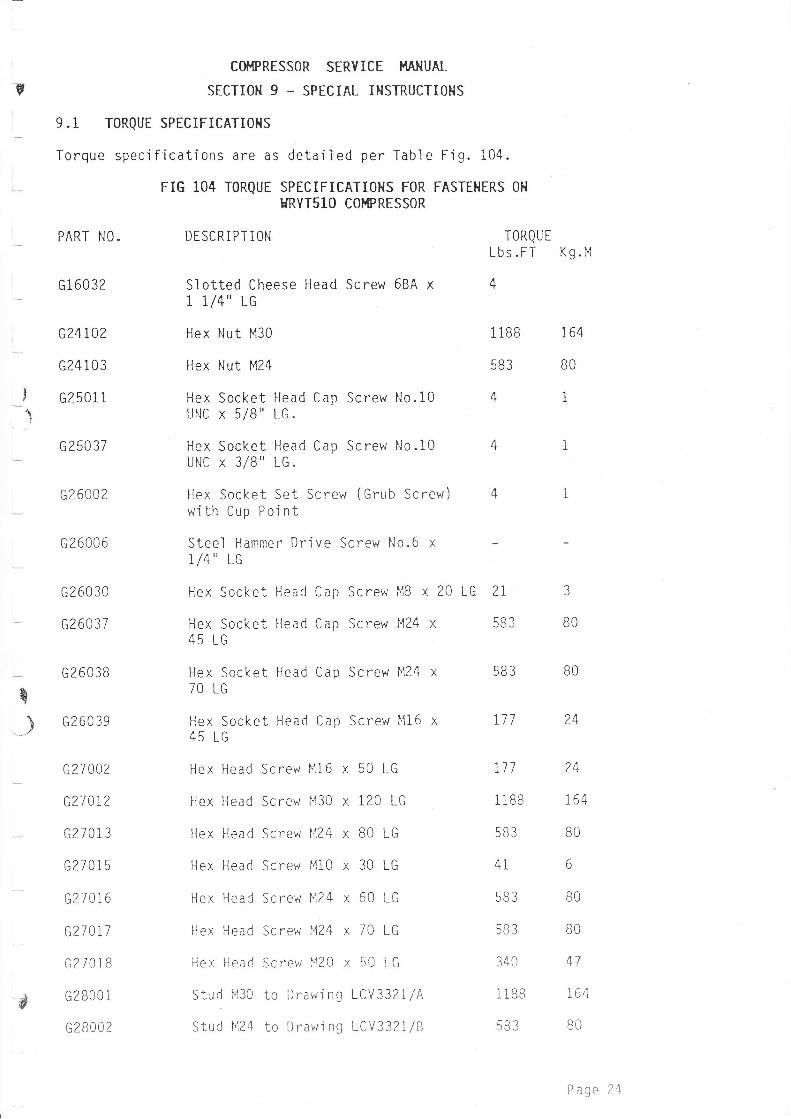
9.i ToRQUE SPECIFICATI0T{S
Torque specifications are as
PART NO.
G16032
G24102
G24103
G2501 1
G250 37
G26002
G26006
G26030
G26037
G26038
G260 39
G27002
G27012
GZ70l3
G270 1 5
G270i6
G?7017
G27018
G2800 I
G2800 2
FrG 104 T0RqUE
DESCRIPTlON
detai 1 ed per Tabl e Fi g. 104.
SPECIFICATIOHS FOR FASTEHERS OH
HRVT51O COI.PRESSOR
Slotted Cheese Head Screw 68A x1 1/4" 1G
Hex Nut M30
Hex Nut M24
Hex Socket Head Cap Screw N0.10UNC x 5/8" LG.
Hex Socket Head Cap Screw l{o.10UNC x 3/8" LG.
Hex Socket Set Screw (Grub Screw)with Cup Pojnt
Steel Hammer Drive Screw No.6 x1/4" LG
Hex Socket Head Cap Screw MB x 20
Hex Socket Head Cap Screw M24 x45 LG
Hex Socket Head Cap Screw M24
70 LG
Hex Socket Head Cap Screw l'116
45 LG
Hex Head Screw Ml6 x 50 LG
Hex Head Screw M30 x 120 LG
Hex Head Screw ll24 x B0 LG
Hex Head Screw M10 x 30 LG
Hex Head Screw 1124 x 60 LG
Hex Head Screw M24 x 70 LG
liex l{ead Screvr 1"120 x 50 tG
Stud 1430 to Drawi ng LCV332l/A
Stud t'124 to Drawi ng LCV332l/B
r c )1 ?LU LL J
583 BO
IORQUE
Lbs.FT Kg.l'1
4
liBB 164
583 BO
41
583
t71
777
liBB
4i
30J
1/ n
1 IBB
583
t+
?4
tb4
BO
6
BO
BO
47
154
BO
BO
ry
B
?
P age 24
COI{PRESSOR SERYICE HANUAL
!- sEcTI0N 9 - SPECIAL IHSTRUCTIoHS
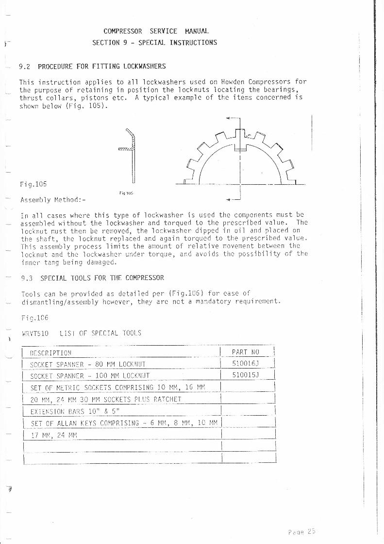
9.? PROCEDURE FOR FITTII{G LOCKI{ASHERS
This instruction applies to all lockwashers used on Howden Compressors forthe purpose of reta'ining'in pos'ition the locknuts locating the bearings,thrust collars, pistons etc. A typical example of the items concerned isshown below (rtg. 105).
Fi 9.105
Assemt-rly Method: -
In all cases where this type of lockwasher is used the components must be
assembled without the lockwasher and torqued to the prescribed value. The
locknut must then be removed, the lockwasher d'ipped in oil and placed on
the shaft, the locknut replaced and aga'in torqued to the pr^escribed value.This assembly process limjts the amount of relative movement between thelocknut and the lockwasher under torque, and avoids the possibility of theinner tang being damaged.
9.3 SPECIAL TOOLS FOR THE COI'{PRESSOR
Tools can be provjded as deta'i1ed per (fig.106) for ease ofdismantling/assembiy however, they are not a mandatory requirement.
v**11
ilIIU
Fis lO5
t
Fig.106
'ilRVT510LIST OF SPECIAL TOOLS
i oescnrPlroN I ennr No I
I socrEr sPANNER - Bo HH LocKlluT I stooieJ I
I socrrr saANNER - 100 MM LocKNUT I s10015J
I sEr on ltrrntc socrrrs coupntsiNe to ttt'i, to MM I I
I zo ulr, z+ NN :o ltu socrErs plus nnrcHrr I I
I ExtrNsioN enRs to" a s" I I
I srr or RLLnN rrvs compRrstNe - o Ftlt, B tltt, to ttM I I
I rz rru, zq H[1 I I
3
- ^-Pacle z-'
B
COI'IPRESSOR SERYICE I'IAHUAL
SECTIO}I 9 - SPECIAL IHSTRUCTIONS
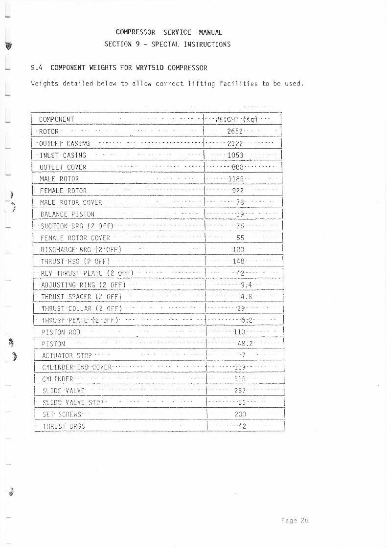
9.4 COMPOHEIT I{EIGHTS FOR I{RYTs1O COI.IPRESSOR
l,leights detailed below to allow correct lifting facilities to be used"
I coueourur I wrrcHT-(Kg) '
RoToR I-2652-
l .ourlrr cASING I zw t
I rNlrr cASTNG 1053
OUTLET COYER
I Nnr-r RoToR 1 tB6
FEMALE ROTORttt I r'rarr RoToR covER
BALANCE PISTON
l- sucr roN -BRG '( 2 of f )'
I rrmnlr RoroR covER I
DISCHARGE-BRG I2.OFF) -
THRUST HSG (2 OFF)
I nrv 'niRUSr'PLATE (z orr) - ]
Inolusrrrucnnic(zorr) -' - j -- -g,e I
I rHnusr sPACTR (z orr) I 4:B I
I rHnusr colLAR (2 oFF) 1 'zs I
I runusr Pi-ATE "('2 oFF) ' '6.2 I
I ersroru noo 1i0 - '
q
9 I ncrunroR sToP I
PrsToN l
CYLINDIR END COVER I - iie I
i cvt- t runrn 516
I slroe vALYEI)I
"' 257
I sL rrr vALVr sToP ccJJ
I srr scRrils 200
I rHnusr eacs ct
\-#
Hage r0