wsm-sv150/04-en - texas · pdf filecentres service, disassemble and repair sv150 engines. each...
TRANSCRIPT

Rel. 1.0 - 01/2005
The manufacturer reserves the right to make all the necessary technical or commercial improvements to its products, sothere may be some differences between the series of lawnmowers and the contents of this manual. However the basic speci-
fications and different operating procedures will remain the same.
by
WORKSHOPMANUAL
SSSSVVVV111155550000

MAIN CHAPTERS
1. Rules and procedures for Service Centres
This chapter covers all the main aspects of therelationship between the manufacturer and theservice centres.A close collaboration between the manufacturerand the service centres is conclusive for solvingproblems in the most effective way as well asmaintaining an image of efficiency and reliability.Compliance with these brief and simple guide-lines will facilitate this task and prevent generalmisunderstandings and time-wasting for boththe manufacturer and the service centre.
2. General and safety regulations
This chapter covers the main aspects of a serv-icing procedure and the general rules for guaran-teeing a successful service which protects theenvironment and respects the safety of both theserviceman and the user of the apparatus.
3. Technical data and specifications
This chapter summarizes all the technical infor-mation regarding the engine, tuning data, tight-
ening torques, expendable materials and spareparts available.
4. Engine tuning
This chapter describes how to plan a mainte-nance program and outlines a servicing proce-dure for general engine tuning.
5. Troubleshooting
This chapter summarizes all the main operatingfaults and indicates probable causes and proce-dures for solving them.
6. Servicing procedures
This chapter describes the servicing proceduresfor dealing with the most frequent operatingfaults.The descriptions follow a logical sequence andmay cover operations not strictly linked to theone described.In this case, you should read the entire proce-dure carefully so that you can leave out any irrel-evant operations without missing necessarysteps.
01/2005
SV 150
i.0TABLE OF CONTENTS
��
�� 1 / 1� �
WORKSHOP MANUAL
page
from 2004 to ••••
CONTENTS
ii 0 Introduction
1.1 0 Rules and procedures for Service Centres
2.1 0 General and safety regulations
3.1 0 Technical data and specifications
4.1 0 Testing and tuning the engine
5.1 0 Troubleshooting
6.1 0 Tank and supply 6.2 0 Starting system6.3 0 Intake system6.4 0 Carburation6.5 0 Carburettor governor system 6.6 0 Ignition system6.7 0 Turning off and stopping the engine6.8 0 Exhaust system6.9 0 Engine block
INTRODUCTION
The purpose of this manual is to help ServiceCentres service, disassemble and repair SV150engines.
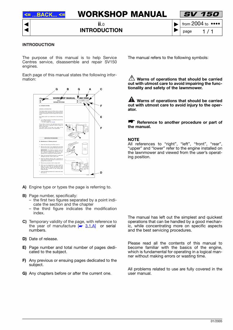
Each page of this manual states the following infor-mation:
A) Engine type or types the page is referring to.
B) Page number, specifically: – the first two figures separated by a point indi-
cate the section and the chapter– the third figure indicates the modification
index.
C) Temporary validity of the page, with reference tothe year of manufacture [� 3.1.A] or serialnumbers.
D) Date of release.
E) Page number and total number of pages dedi-cated to the subject.
F) Any previous or ensuing pages dedicated to thesubject.
G) Any chapters before or after the current one.
The manual refers to the following symbols:
Warns of operations that should be carriedout with utmost care to avoid impairing the func-tionality and safety of the lawnmower.
Warns of operations that should be carriedout with utmost care to avoid injury to the oper-ator.
Reference to another procedure or part ofthe manual.
NOTEAll references to “right”, “left”, “front”, “rear”,“upper” and “lower” refer to the engine installed onthe lawnmower and viewed from the user’s operat-ing position.
The manual has left out the simplest and quickestoperations that can be handled by a good mechan-ic, while concentrating more on specific aspectsand the best servicing procedures.
Please read all the contents of this manual tobecome familiar with the basics of the engine,which is fundamental for operating in a logical man-ner without making errors or wasting time.
All problems related to use are fully covered in theuser manual.
�
01/2005
SV 150
ii.0INTRODUCTION
��
�� 1 / 1� �
WORKSHOP MANUAL
page
from 2004 to ••••
6.3 INTAKE SYSTEM
GENERAL INFORMATION
The intake system uses an air filter which is directlyconnected to the carburettor and a manifold whichconveys the air/petrol mixture towards the inductionvalve.
The intake system can malfunction in the followingways:
• no or difficult starting or insufficient power (if notdue to other causes): = Air filter clogged [� 6.3.A];
The air filter is found on the right hand side of theengine and can be inspected without having toremove other parts.The entire body of the filter only needs to beremoved in case of access to the carburettor.
SERVICING PROCEDURES
A) Maintenance of filtering element
1 Clean the area around the filter cover (1).
2 Remove the cover (1) by releasing the rear flap(2) and remove the sponge filtering element (3).
IMPORTANT! The filtering element must bekept clean and soaked in oil. Replace it if bro-ken, cracked or fragmented. Do not use com-pressed air for cleaning the filtering element.
3 Wash the sponge filtering element in water anddetergent and dry it with a clean cloth.
4 Soak the filtering element with 2 spoonfuls ofclean engine oil and squeeze it several times tospread the oil evenly (4).
5 Remove any excess oil with a clean cloth.
6 With a jet of compressed air, clean inside thebody (5) of the filter by removing dust andremains of grass, making sure that the intakepipe hole (6) is closed so that nothing getsinside the pipe.
7 Install the filtering element (3) in place and closethe cover (1).
SV 150
6.3.0INTAKE SYSTEM
��
�� 1 / 2� �
WORKSHOP MANUAL
page
from 2004 to ••••
01/2005
4
6
2
5
3
3
1
1
A C
F
E
F
D
GBG

1.1 RULES AND PROCEDURES FOR SERVICECENTRES
A) Warranty validity
The warranty is supplied under the terms, pro-cedures and limits stated in the contract.
B) Post-warranty assistance
The Service Centre is obliged to compile areport for every service, stating the engine seri-al number[� 3.1.A], the summary of claims, theoperation carried out and any spare parts used.
A copy of these reports must be kept and madeavailable to the manufacturer together with thereplaced parts, in case clients should make fur-ther complaints.
C) Fault notification
The manufacturer should be informed of allfaults that recur frequently; this allows it to care-fully examine the problem and make correctionson the production line.Similarly, the manufacturer shall report anyfaults traced on its engines, indicating the besttroubleshooting procedure.
D) Requesting spare parts
When asking for spare parts, you must quotetheir code by referring to the exploded viewscorresponding to the year of manufacturereported on the nameplate [� 3.1.A].
01/2005
SV 150
1.1.0RULES AND PROCEDURES FOR SERVICE CENTRES
��
�� 1 / 1� �
WORKSHOP MANUAL
page
from 2004 to ••••

2.1 GENERAL AND SAFETY REGULATIONS
A) Qualification of operators
All maintenance, disassembly and repairs must becarried out by expert mechanics who are familiarwith all the accident prevention and safety regula-tions after reading through the procedures in thismanual.
B) Safety measures
All the engines are built in conformity with theEuropean safety regulations in force.
To maintain initial safety levels in the long term, theService Centre should take proactive measures bymaking checks whenever possible.
Every time you are asked to service the engine (orthe lawnmower on which it is installed), you should:
1) check:
– that the safety devices function correctly;– that the guards and covers have not been
removed;– that the nameplates or specification labels
have not been removed or made illegible,as they form an integral part of the safetydevices.
2) also:
– make sure the safety devices function cor-rectly if they have been tampered with orremoved;
– replace ineffective, damaged or missingguards and covers;
– replace illegible labels;– do not carry out operations or modifica-
tions on the lawnmower or on the enginethat could affect their performance or leadto an improper or different use from theone for which it has been designed andapproved;
– warn the customer that the failure to com-ply with the above points automaticallyvoids the warranty and the responsibility ofthe manufacturer.
C) Precautions during servicing
The operations described in this manual do notentail particularly hazardous situations besides the
normal hazard related to mechanical operationsand that can be avoided by taking the necessarycare and attention normally required for this type ofwork.
As well as following the usual accident preventionregulations that apply to most repair shops, we rec-ommend you:
– disconnect the spark plug cap before servic-ing;
– protect hands with suitable working gloves,especially when working near the cutting unit;
– check that you do not cause accidental petrolleaks or other losses;
– do not smoke when working on the tank orwhen handling petrol;
– do not inhale oil or petrol fumes; – clean up all traces of spilt petrol immediately; – test the engine in a well-ventilated environ-
ment or where there are adequate exhaustfume extraction systems;
– do not pollute the environment with oil, petrolor other waste and dispose of all waste inaccordance with the laws in force.
D) Necessary equipment
All the operations can be carried out with the toolsnormally used in a good garage.
Some operations require special equipment andtools [� 3.1.F].
E) Symbols and terms used for safety purposes
Some paragraphs in this manual are preceded bysymbols which indicate the following:
Operations that should be carried out withutmost care to avoid impairing the functionalityand safety of the engine and/or lawnmower onwhich it is installed.
Operations that should be carried out withutmost care to avoid injury to operators.
“WARNING” stresses the risk of injury to oneselfand others if instructions and regulations are notobserved.
01/2005
SV 150
2.1.0GENERAL AND SAFETY REGULATIONS
��
�� 1 / 1� �
WORKSHOP MANUAL
page
from 2004 to ••••

A) Identification
All the engines have aserial number stampedon the right-hand side ofthe crankcase; this 9-figure code identifies:
The serial number must be reported on everyoperating sheet in the warranty application andis fundamental for identifying and ordering spareparts.
B) Technical data
Piston displacement .................................... 149 ccBore ............................................................. 65 mmStroke .......................................................... 45 mmMinimum speed (SLOW) ................ 2200-2500 rpmMaximum speed (FAST) ................ 2800-3000 rpmFuel tank capacity ..................................... 0.8 litresOil sump capacity ..................................... 0.6 litres
C) Adjustments
Distance between spark plug electrodes ............................................. 0.6-0.8 mmCoil air gap ....................................... 0.25-0.40 mm
D) Summary of tightening torques
The first number refers to the procedure, while thenumber in brackets is an internal reference to theprocedure.
6.1 Conveyor nuts (2) ................................ 4-7 Nm6.2 Starter screw (6) .................................. 4-6 Nm6.3 Governor bracket screw (7) ................. 6-8 Nm 6.3 Carburettor screws (8) ......................... 6-8 Nm6.5 Cylinder head screws (34) ............... 20-25 Nm6.6 Spark plug tightening torque (1) ...... 16-18 Nm6.8 Muffler nuts (3) ..................................... 6-8 Nm6.9 Cylinder head screws (4) (6) ............ 20-25 Nm6.9 Oil drain plug (12) ............................ 18-22 Nm6.9 Engine screws (23) .......................... 20-28 Nm
E) Expendable materials
Petrol ........................................... lead-free (green)minimum lead-free (green) min-imum 90N.O.
Engine oil - from 5 to 35 ° C ....... SAE 30from -15 to +5 °C ..... 5W30 - 10W30from -25 to + 35°C ... synthetic 5W30
- 10W30Spark plug ................................... GL4RC Torch or
equivalentStarter cable ................................ Ø 4.5x2400 mm
F) Special equipment
The number refers to the procedure whichdescribes the servicing operation.
Speed indicator ......................................... 6.4 - 6.5Tester for spark test ........................................... 6.6Universal tester................................................... 6.7
01/2005
SV 150
3.1.0TECHNICAL DATA AND SPECIFICATIONS
��
�� 1 / 2� �
WORKSHOP MANUAL
page
from 2004 to ••••
• - ••• - •••••
Year of manufactureDateDaily progressive number

G) Spare parts
Below is a list of spare parts available, not includingparts that are easily available or whose replacementwould entail particularly expensive assembly anddisassembly operations.
To order a spare part, refer to the code on theexploded view regarding the year of manufacture.
1 Complete Sumec SV 150 engine 2 Starter/tank conveyor assembly 3 Tank cap 4 Starter handle 5 Deflector 6 Starter spring 7 Starter assembly8 Starter hook kit 9 Fuel pipe
10 Conveyor stud bolt kit 11 Nut12 Oil level pipe assembly 13 Air filter base14 Screw
15 Filtering element 16 Air filter cover 17 Breather pipe 18 Governor bracket19 Governor spring 20 Spring21 Carburettor22 Governor tie rod 23 Carburettor tie rod24 Carburettor gasket kit25 Governor fin disc kit26 Brake27 Cable clamp 28 Screw29 Ignition coil30 Spark plug cap 31 Spark plug 32 Cylinder head gasket 33 Stud bolt 34 Muffler gasket 35 Muffler spacer 36 Muffler37 Nut38 Muffler cover
01/2005
SV 150
3.1.0TECHNICAL DATA AND SPECIFICATIONS
��
�� 2 / 2� �
WORKSHOP MANUAL
page
from 2004 to ••••
34 35 36 38
33 37
12
4311
9
1026
2523
24212224
14 15 1317
2728
20
30
19
31
67
8
2
16
18
29
32
5
10
24
1

4.1 ENGINE TUNING AND TESTING
A) Operating guidelines
The instruction manual describes a series of opera-tions for the client to ensure minimum basic main-tenance. For operations beyond the client’s capa-bility, the Service Centre should see to keeping theengine in perfect working order by:
– Tuning the engine whenever possible.– Recommending the client a routine maintenance
program at set intervals (e.g. at the end of theseason or before a long period of inactivity).
B) Engine tuning program
Whenever the Service Centre is asked to service alawnmower or tune an engine, it should follow aseries of operations to ensure the engine is keptfully serviceable.
Tuning should involve:
– external blowing and cleaning the cylinder head,cylinder and muffler by removing any remains ofgrass and mud;
– checking the oil level, topping up or replacingparts if necessary;
– inspecting the condition of the starter cable andchecking that it functions correctly;
– cleaning and oiling the air filter [� 6.3];
– emptying and cleaning the fuel tank and check-ing the breather pipe [� 6.1];
– adjusting minimum and maximum speeds [� 6.4and 6.5];
– inspecting the condition of the spark plug andignition cable; checking the distance between theelectrodes [� 6.6];
– tightening the screws [� 6.9];
– functional test [� point “C”].
Should the checks and adjustments fail to achievea satisfactory result, refer to chapter 5 for trou-bleshooting.
C) Functional test
A functional test needs to be carried out at the endof each servicing operation, to check that the oper-ations made are effective. The test must be per-formed in compliance with the safety regulationsregarding the use of the lawnmower on which theengine is installed.
The functional test is carried out as follows.
1. Refuelling and checking the supply system.When you have refuelled the tank with new petrol,check the seal of the tank, the cap and the carbu-rettor pipe.
2. Cold start test. With the throttle control in“CHOKE”, start the engine a few times to check itruns normally.
3. Check the engine rpm. When the engine is hotenough, check the engine speed with the throttlecontrol set to “SLOW” and “FAST”; the readingsshould be equal to the specifications [� 3.1.B].
4. Hot start test. With the engine hot and the throt-tle control set to “SLOW”, start the engine a fewtimes to check it runs normally.
5. Engine brake and stopping test. If you releasethe lawnmower brake lever, the engine should turnoff instantaneously and decisively, and the rotationshould stop within 3 seconds.
If all of these operations have a positive result, theengine can be considered fully serviceable and bereturned to the client.
01/2005
SV 150
4.1.0ENGINE TUNING AND TESTING
��
�� 1 / 1� �
WORKSHOP MANUAL
page
from 2004 to ••••
Lawnmower problems
The engine brake cable isfaulty or unfastened
Electrical problems
The microswitch is faulty
Electric current does not reachthe spark plug
Engine block problems
Fouling in the combustionchamber
Insufficient pressure
Lawnmower problems
The lawnmower blade is loose
Intake problems
Air filter is clogged up
The cable control does not activate the coil earthswitch.
If the microswitch remains locked in the pressedposition, it does not stop the coil earth connec-tion.
The spark plug is badly connected, faulty or theelectrodes are too far away.
The coil is faulty and does not supply current orthe air gap is too large.
Fouling in the combustion chamber absorbs thefresh mixture, which makes starting difficult andmay impair valve closure.
The cylinder head screws can loosen causingthe gasket to burn.
The piston rings can wear out due to the pas-sage of dust caused by an excessively dirty orunoiled air filter or overheating due to the lack ofoil.
The loose blade stops the effect of the flywheeland the kick-back can make starting difficult.
The clogged filter can thicken the mixture flood-ing the engine.
Adjust and/or replacethe cable [� 6.7.A]
Replace themicroswitch [� 6.7.B]
Check the spark plugand the efficiency ofthe ignition systemwith the spark test [�6.6.A]
Dismount the cylinderhead and remove foul-ing [� 6.9.A]
Dismount the cylinderhead and replace thegasket [� 6.9.A]
Change the engine[� 6.9.C]
Check that the lawn-mower blade and hubare securely fastened
Check and clean theair filter [� 6.3.A]
01/2005
SV 150
5.1.0TROUBLESHOOTING
��
�� 1 / 5� �
WORKSHOP MANUAL
page
from 2004 to ••••
A) The engine does not start
Probable cause Comment Solution
B) The engine starts badly or kicks back
Probable cause Comment Solution

Carburation problems
Carburettor is dirty
Poor seal of carburettor needlevalve
Choke blocked
Lawnmower problems
The lawnmower traction cable(if present) is bent, jammed orpoorly adjusted
Problems caused by theengine
Oil in the cylinder head
Supply problems
The tank cap has a cloggedbreather pipe
If the jet and the pipes inside the carburettor clogup, the petrol flow drops and the engine fails tofunction correctly.
If the needle valve does not close, excess fuel inthe float chamber can reach the combustionchamber through the intake manifold. This canflood the engine and be hazardous as the petrolcan seep through the rings and reach the oilsump. When mixed with petrol, oil loses its lubri-cating properties and the engine deterioratesrapidly.
The choke can get blocked in the closed posi-tion if the mixture is too oily.
The engine must start with the lawnmower drivecompletely disengaged; a poorly adjusted cablecan generate faulty resistance which makesstarting more difficult.
If the engine is tilted with the spark plug at thebottom, oil may seep into the cylinder headthrough the rings. This causes excess pressureand a reduction of mixture in the combustionchamber.
The clogged breather pipe in the tank stops theregular flow of fuel into the carburettor floatchamber. When the fuel has run out in the float
Check and clean thecarburettor [� 6.4.A]
Clean the carburettorhousing and needlevalve [� 6.4.A] orreplace the carburettor[� 6.4.B]
Check and clean thecarburettor [� 6.4.A]and the choke
Check and/or adjustthe lawnmower trac-tion cable
Dismount the cylinderhead and clean it [�6.9.A]
Clean and/or replacethe cap [� 6.1.C]
01/2005
SV 150
5.1.0TROUBLESHOOTING
��
�� 2 / 5� �
WORKSHOP MANUAL
page
from 2004 to ••••
C) Starting is difficult and strains the cable
Probable cause Comment Solution
D) The engine starts but does not run
Probable cause Comment Solution

Fuel filter clogged
Ignition problems
Insufficient or no current to thespark plug
Lawnmower problems
The throttle cable is not welladjusted
Carburation problems
Carburettor dirty
The governor malfunctions orthere is a problem with the tierods
Insufficient pressure
chamber, the engine stops. After a few minutes,the float chamber fills up and the engine is ableto restart, only to stop soon after.
Inside the tank, the filter has a metal mesh whichcan clog up with dirt or with a film of old fuel.
Poor connections of the electrical cables or mal-functioning parts can cause the lawnmower tofunction irregularly.
The throttle’s “FAST” position may not corre-spond with the carburettor’s “FAST” position,reducing the flow of mixture and hence thepower.
If the jet and pipes inside the carburettor clogup, the petrol supply drops and the enginebecomes less efficient.
The pneumatic governor fin disc is broken ordoes not move freely and therefore fails to workthe carburettor correctly.
The bent or warped governor rods are bent,deformed or do not move freely, preventing thegovernor from reaching its end-of-stroke.
The piston rings can wear out due to the pas-sage of dust or overheating caused by the lackof oil.
The cylinder head screws can loosen causingthe gasket to burn.
Empty and clean thetank [� 6.1.B]
Check the spark plugand the efficiency ofthe ignition systemwith the spark test [�6.6.A]
Check and/or adjustthe throttle cable [�6.5.A]
Check and clean thecarburettor [� 6.4.A]
Check the entire gov-ernor system [� 6.5]
Replace the engine[� 6.9.C]
Dismount the cylinderhead and replace thegasket [� 6.9.A]
01/2005
SV 150
5.1.0TROUBLESHOOTING
��
�� 3 / 5� �
WORKSHOP MANUAL
page
from 2004 to ••••
E) The engine is inefficient (insufficient power)
Probable cause Comment Solution

Environmental problems
The engine is used at a highaltitude
Carburation problems
Air seeps into the carburettor
The governor malfunctions orthere is a problem with therods
Starting problems
The coil air gap has beenpoorly adjusted
Carburation problems
Governor blocked
Lawnmower problems
The engine brake cable is bentor jammed
The rarefaction of air in the mountains causes adrop in power of approx. 10-12% every 1000metres of altitude.
If air seeps through the gaskets, it can cause thelawnmower to function poorly and make it diffi-cult to maintain the minimum speed (2200-2500rpm).
The pneumatic governor fin disc is broken ordoes not move freely and therefore fails to workthe carburettor correctly.
The governor rods are bent, deformed or do notmove freely, preventing the governor from reach-ing its end-of-stroke.
The air gap adjustment between the flywheeland coil must be 0.25-0.40 mm.
Excess dirt or a broken spring can impede themovements of the governor or impede return.
When the lever is released, the earthmicroswitch is not pressed.
Advise your client toadapt the strain of thelawnmower to the lim-ited power available.
Replace the carburet-tor gaskets [� 6.4.A]
Check the entire gov-ernor system [� 6.5]
Adjust the air gap [�6.6.B] and if the prob-lem persists, replacethe coil [� 6.6.C]
Check the governor[� 6.5.B]
Check and/or adjustthe cable [� 6.7.A]
01/2005
SV 150
5.1.0TROUBLESHOOTING
��
�� 4 / 5� �
WORKSHOP MANUAL
page
from 2004 to ••••
F) The engine runs irregularly
Probable cause Comment Solution
G) The engine overreved
Probable cause Comment Solution
H) The engine does not turn off
Probable cause Comment Solution

Electrical problems
The earth cable is disconnect-ed or broken
Lawnmower problems
Blade not balanced
Engine screws loose
Problems with the stoppingsystem
Faulty or no clutch lining
The broken or disconnected cable prevents themicroswitch from closing the electric circuit toearth
The imbalanced or loose blade causes juddersand the premature wear of all the parts inside theengine.
An engine with loose screws can be hazardousfor the user and can break internal parts.
The thickness of the clutch lining normally guar-antees good braking action for the entire dura-tion of the engine.
If it comes away from the lever, act immediatelyto stop the metal from rubbing against the fly-wheel causing hazardous sparks.
Check the earth con-nection [� 6.7.B]
Dismount and balancethe blade and tightenthe screws to thespecified levels
Tighten the screws tothe specified levels [�6.9.C]
Replace the enginestopping system [�6.7.D]
01/2005
SV 150
5.1.0TROUBLESHOOTING
��
�� 5 / 5� �
WORKSHOP MANUAL
page
from 2004 to ••••
J) The engine judders
Probable cause Comment Solution
K) The engine does not stop within 3 seconds after it has turned off
Probable cause Comment Solution

6.1 TANK AND SUPPLY
GENERAL INFORMATION
The supply system consists of a petrol tank (builtinto the upper conveyor) connected to the carburet-tor by a pipe. A mesh filter on the bottom of the tankstops deposits and impurities from reaching thecarburettor.
The supply to the carburettor float chamber iscaused by gravity and the volume of petrol takenfrom the tank as the engine runs is compensated bya breather pipe in the cap.
The supply system can malfunction in the followingways:
• difficult or failed start or insufficient power (if notdue to other causes): = Petrol filter dirty [� 6.1.B];= Petrol pipes clogged;= Inefficient breather pipe [� 6.1.C].
SERVICING PROCEDURES
WARNING! All work on the tank and on the sup-ply system must be carried out in safe condi-tions, so:
– do not smoke;– always empty the tank;– work in a ventilated environment away from
naked flames or unprotected sources of heat;– collect petrol in a suitable container with a
cap using a funnel and avoid spilling it on thework bench;
– remove all traces of spilt petrol immediately;– check you have connected the pipes before
pouring petrol back into the tank
A) Emptying and removing the tank
1 Remove the conveyor (1) secured by three nuts(2).
2 Remove the ring (3) of the petrol pipe (4) fromthe carburettor side and drain all the fuel fromthe tank into a suitable container.
3 For assembly, follow the above procedures in
SV 150
6.1.0TANK AND SUPPLY
��
�� 1 / 2� �
WORKSHOP MANUAL
page
from 2004 to ••••
01/2005
3
2
4
2
21
6

reverse order.
WARNING! Check that the petrol pipe (4) isintact and secured correctly before pouring innew fuel.
B) Cleaning the tank
11 Remove the conveyor (1) secured by three nuts(2).
12 Remove the ring (5) from the tank side, discon-nect the petrol pipe (4) and drain all the fuel fromthe tank into a suitable container.
13 Remove the tank cap (6) and blow compressedair through the tube (7) to remove deposits fromthe internal mesh filter.
14 Keep the tube hole (7) closed, pour in approx.100 cl of clean petrol and shake well to cleaninside the tank.
15 Empty the tank and dispose of the petrol usedfor cleaning in accordance with the laws inforce.
16 Remount the conveyor.
WARNING! Check that the petrol pipe (4) isintact and secured correctly before pouring innew fuel.
C) Checking and cleaning the breather pipe
21 Remove the cap (6) and pull out the gasket (8)and the sponge (9).
22 Check that: – the gasket (8) is intact and without cracks or
fissures;– the air passages (10) inside the cap are not
clogged;– the sponge (9) is not crushed or broken.
NOTEAlways replace the entire cap if the gasket orsponge is damaged.
Tightening torques
2 Conveyor nuts ...................................... 4-7 Nm
SV 150
6.1.0TANK AND SUPPLY
��
�� 2 / 2� �
WORKSHOP MANUAL
page
from 2004 to ••••
01/2005
10
8
6
5
4
6
8 9
7

6.2 STARTING SYSTEM
GENERAL INFORMATION
The starting system is built into the upper conveyor(which also includes the tank) and consists of acable wound onto a pulley.The movement from the pulley to the flywheel (andthe engine shaft) is transmitted by a pair of hooks.The cable is returned and rewound by a spiralspring.
Other than the possibility of the cable breaking, thestarting system may malfunction in the followingways:
• failed start after attachment (if not due to othercauses): = cable too short, therefore does not supply
adequate number of revs to the engine [�6.2.A].
• the pulley is not attached to the flywheel. Thiscan be detected when the cable unwinds with-out strain := the hooks are deformed or broken [� 6.2.B].
• inefficient or no return of the cable: = spring broken [� 6.2.C].
In all cases, remove the conveyor to make the nec-essary checks or repairs.
SERVICING PROCEDURES
A) Replacing the cable
1 Remove the conveyor with the tank [� 6.1.A].
2 Remove the internal screen (1) fastened by thescrew (2).
3 Keep hold of the pulley (3) and slowly unwind(clockwise) the entire cable (4) to graduallyrelease the return spring. If the cable breaks, thespring will be already released and you will onlyhave to unwind the cable.
4 Undo or cut the knot at the end of the cable orremove the section still attached to the pulley.
5 Cut a section of cable (4) (Ø 4.5 mm and 2.40 mlong), fit one end in the pulley hole (3) and makea knot to prevent it from slipping out.
SV 150
6.2.0STARTING SYSTEM
��
�� 1 / 3� �
WORKSHOP MANUAL
page
from 2004 to ••••
01/2005
5
3
4
4
4
21
3

6 Fit the other end of the cable in the conveyorhole, securing it to the handle (5) with a knot.
7 Turn the pulley (3) and the cable (4) anticlock-wise for approx. 5 complete revs to load thespring, then release the pulley carefully to windthe entire cable onto the pulley.
8 Check that the pulley (3) is free to rotate.
9 After pulling the entire length of the cable, checkthat the pulley (3) is able to complete 2-3 turnsbefore compressing the spring.
10 Remount the internal screen (1).
11 Remount the conveyor [� 6.1.A].
B) Replacing the hooks
21 Remove the conveyor with the tank [� 6.1.A].
22 Loosen the central screw (6) and dismount thebushing (7) and hooks (8) without letting the pul-ley (3) slip out of place.
NOTEThe screw (6) has a left-handed thread andtherefore should be unscrewed clockwise.
NOTEAlways replace the hooks (8), the bushing (7)and the screw (6) in one block.
23 Mount the new hooks (8), taking care to positionthem correctly with the bushing (7) and theguides in the pulley hub (3). Tighten the screw(6) anticlockwise so that the pulley rotatessmoothly.
24 Remount the conveyor [� 6.1.A].
C) Replacing the pulley
31 Remove the conveyor with the tank [� 6.1.A].
32 Dismount the internal screen (1) fastened by thescrew (2).
SV 150
6.2.0STARTING SYSTEM
��
�� 2 / 3� �
WORKSHOP MANUAL
page
from 2004 to ••••
01/2005
8
8
3
68
3
4
87
7
7
6

33 If the spring is not already released, keep holdof the pulley (3) and slowly unwind the entirecable (4) clockwise to release the return springgradually.
34 Dismount the hooks [� point “B”].
35 Remove the pulley (3), making sure that thereturn spring (9) stays in place underneath thepulley.
WARNING! Carry out this operation withutmost care to avoid injury when the springsuddenly unwinds, as it could slip out ofplace.
36 Clean the inside of the conveyor with degreas-ing liquid by removing any leftover dirt orgrease.
37 Cut a section of cable (4) (Ø 4.5 mm and 2.40 mlong), fit one end in the pulley hole (3) and makea knot to stop it from slipping out.
38 Fit the other end of the cable in the conveyorhole and secure it to the handle (5) with a knot.
39 Spray some silicone lubricant onto the spring (9)and apply liquid grease to inside the conveyorhousing. Check that the spiral spring (10) issecurely lodged in the conveyor housing andput the pulley (3) back in place so that the insideend of the spring (9) is firmly lodged in the sloton the conveyor.
40 Refit the hooks [� point “B”].
41 Turn the pulley (3) and the cable (4) anticlock-wise for 5 complete turns in order to load thespring, then release the pulley carefully to windthe entire cable onto the pulley.
42 Check that the pulley (3) rotates freely.
43 After pulling the entire length of the cable, checkthat the pulley (3) is able to complete another 2-3 turns before compressing the spring.
44 Remount the internal screen (1).
45 Remount the conveyor [� 6.1.A].
Tightening torques
6 Starter screw ........................................ 4-6 Nm
SV 150
6.2.0STARTING SYSTEM
��
�� 3 / 3� �
WORKSHOP MANUAL
page
from 2004 to ••••
01/2005
10
9
93

6.3 INTAKE SYSTEM
GENERAL INFORMATION
The intake system uses an air filter which is directlyconnected to the carburettor and a manifold whichconveys the air/petrol mixture towards the inductionvalve.
The intake system can malfunction in the followingways:
• no or difficult starting or insufficient power (if notdue to other causes): = Air filter clogged [� 6.3.A];
The air filter is found on the right hand side of theengine and can be inspected without having toremove other parts.The entire body of the filter only needs to beremoved in case of access to the carburettor.
SERVICING PROCEDURES
A) Maintenance of filtering element
1 Clean the area around the filter cover (1).
2 Remove the cover (1) by releasing the rear flap(2) and remove the sponge filtering element (3).
IMPORTANT! The filtering element must bekept clean and soaked in oil. Replace it if bro-ken, cracked or fragmented. Do not use com-pressed air for cleaning the filtering element.
3 Wash the sponge filtering element in water anddetergent and dry it with a clean cloth.
4 Soak the filtering element with 2 spoonfuls ofclean engine oil and squeeze it several times tospread the oil evenly (4).
5 Remove any excess oil with a clean cloth.
6 With a jet of compressed air, clean inside thebody (5) of the filter by removing dust andremains of grass, making sure that the intakepipe hole (6) is closed so that nothing getsinside the pipe.
7 Install the filtering element (3) in place and closethe cover (1).
SV 150
6.3.0INTAKE SYSTEM
��
�� 1 / 2� �
WORKSHOP MANUAL
page
from 2004 to ••••
01/2005
4
6
2
5
3
3
1
1

B) Removing the filter body
11 Clean the area around the filter cover (1).
12 Remove the cover (1) by releasing the rear flap(2) and take out the sponge filtering element (3).
13 To remove the filter body (5), loosen the screw(7) fastening the governor system bracket andthe two screws (8), remembering that both thesescrews also fasten the carburettor to the engineblock.
14 Disconnect the oil vapour circulation pipe (9).
Tightening torques
7 Governor bracket screw ...................... 6-8 Nm8 Carburettor screw ................................ 6-8 Nm
SV 150
6.3.0INTAKE SYSTEM
��
�� 2 / 2� �
WORKSHOP MANUAL
page
from 2004 to ••••
01/2005
5
2
9
8
8
7
1
3
5

6.4 CARBURATION
GENERAL INFORMATION
The carburettor has a float with a fixed jet and a“CHOKE” control.
The carburettor can malfunction in the followingways:
• difficult or failed start or insufficient power (if notdue to other causes):= Carburettor dirty [� 6.4.A].
• engine runs irregularly (if not due to other caus-es): = Air has seeped into the carburettor [�
6.4.A].
SERVICING PROCEDURES
WARNING! All operations on the tank and supplysystem must be carried out in safe conditions,so:
– do not smoke;– always empty the tank if petrol is not strictly
necessary for the operation to be carried out;– work in a ventilated environment away from
naked flames or unprotected sources of heat;– collect petrol in a suitable container with a
cap using a funnel and avoid spilling it on thework bench;
– remove all traces of spilt petrol immediately;– check you have connected the pipes before
pouring petrol back into the tank.
A) Removing and cleaning the carburettor
1 Remove the conveyor with the tank. [� 6.1.A].
2 Remove the air filter [� 6.3.B].
3 Disconnect the two tie rods (1) and (2) and takethe carburettor (3) out of the intake manifold (4).
SV 150
6.4.0CARBURATION
��
�� 1 / 3� �
WORKSHOP MANUAL
page
from 2004 to ••••
01/2005
8
13
6
2
4
1
3
5
9
7

4 Loosen the central screw (5) fastening the floatchamber (6) and carefully collect all the petrolleft in the float chamber.
5 Pull out the pin (7), dismount the float (8) andremove the gasket (9).
6 Undo the screw (10) and pull out the jet (11).
7 Clean the jet and the carburettor thoroughly byimmersing them in clean petrol (or a detergent)for 24 hours. Dry with compressed air, blowingwell through the carburettor holes.
8 Mount the carburettor following the previouspoints 6, 5 and 4 in reverse order, rememberingthat:
– It is always advisable to replace the gasket (9)and the washer underneath the screw (5);
– the float (8) must oscillate freely on the pin (7);
– the jet (11) should never be modified orreplaced with others even if they seem tohave the same specifications;
– the choke (12) must open and close regularly;
– the float chamber drain screw (13) must befacing forwards.
9 When fitting the carburettor back on the engine,always replace the grommet (14) on the mani-fold side and the gasket (15) on the filter side.
10 Remount the tie rods (1) and (2) and check thatthe governor system moves smoothly withoutstopping.
11 Remount the conveyor [� 6.1.A].
12 Remount the air filter [� 6.3.B].
B) Replacing the carburettor
– Follow steps 1 - 2 - 3 - 9 - 10 - 11 - 12 of theprocedure described in point “A”.
SV 150
6.4.0CARBURATION
��
�� 2 / 3� �
WORKSHOP MANUAL
page
from 2004 to ••••
01/2005
14
15
13
10
10
11
9
12

C) Adjusting minimum speed
21 Check that the throttle cable is adjusted cor-rectly [� 6.5.A].
22 Let the engine heat up for a few minutes, thenset the throttle control to “SLOW”. Check therotation speed on the speed indicator (21).
NOTEThe engine’s minimum speed must be between2200 and 2500 rpm.
23 Turn the screw (22) on the carburettor until youachieve a stable minimum speed within theabove values.
D) Adjusting maximum speed
NOTEThis operation is carried out by adjusting thegovernor system [� 6.5.B].
Technical information
Minimum speed (SLOW) .............. 2200-2500 rpm
Special equipment
21 Speed indicator
SV 150
6.4.0CARBURATION
��
�� 3 / 3� �
WORKSHOP MANUAL
page
from 2004 to ••••
01/2005
21
22

6.5 GOVERNOR SYSTEM OF THE CARBURET-TOR
GENERAL INFORMATION
The carburettor’s governor system consists of alever system mounted on a support attached to theengine’s cylinder head, with a built-in pneumaticdevice.
This device consists of a fin disc which tends toclose the carburettor’s choke under the pressure ofthe flywheel air, against the main spring of the con-trol lever. The balance between the throttle controland the push of air on the fin disc adapts the flow ofmixture into the engine depending on the powerrequired.
The governor system can malfunction in the follow-ing ways:
• difficult or failed start or insufficient power (if notdue to other causes): = Incorrect adjustment of the throttle cable [�
6.5.A];= rods bent or deformed [� 6.5.B];= pneumatic device broken or blocked [�
6.5.B].
• Engine runs irregularly (if not due to other caus-es): = pneumatic device broken or blocked [�
6.5.B].
A visual inspection allows you to rapidly identify anybroken or deformed parts, which should always bereplaced.
SERVICING PROCEDURES
A) Adjusting the throttle cable
1 Loosen the screw (1) of the clamp (2) so that thecable sheath (3) runs freely.
2 Set the throttle control lever to “SLOW”.
3 Push the speed governor lever forward as far asreaching the end of stroke (4), keep it in thisposition and secure the cable sheath (3) bytightening the screw (1) of the clamp (2).
SLOW
CHOKE
FAST
SV 150
6.5.0GOVERNOR SYSTEM OF THE CARBURETTOR
��
�� 1 / 3� �
WORKSHOP MANUAL
page
from 2004 to ••••
01/2005
13
2
4
B) Adjusting maximum speed
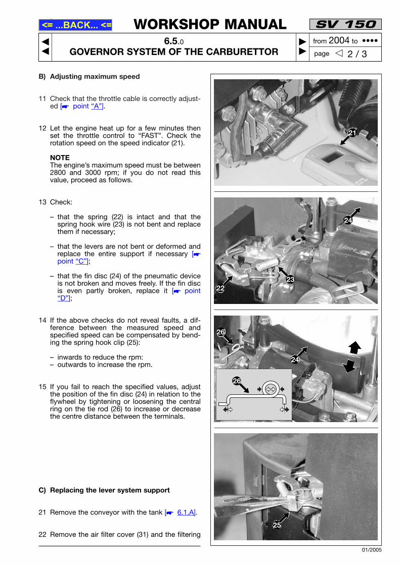
11 Check that the throttle cable is correctly adjust-ed [� point “A”].
12 Let the engine heat up for a few minutes thenset the throttle control to “FAST”. Check therotation speed on the speed indicator (21).
NOTEThe engine’s maximum speed must be between2800 and 3000 rpm; if you do not read thisvalue, proceed as follows.
13 Check:
– that the spring (22) is intact and that thespring hook wire (23) is not bent and replacethem if necessary;
– that the levers are not bent or deformed andreplace the entire support if necessary [�point “C”];
– that the fin disc (24) of the pneumatic deviceis not broken and moves freely. If the fin discis even partly broken, replace it [� point“D”];
14 If the above checks do not reveal faults, a dif-ference between the measured speed andspecified speed can be compensated by bend-ing the spring hook clip (25):
– inwards to reduce the rpm:– outwards to increase the rpm.
15 If you fail to reach the specified values, adjustthe position of the fin disc (24) in relation to theflywheel by tightening or loosening the centralring on the tie rod (26) to increase or decreasethe centre distance between the terminals.
C) Replacing the lever system support
21 Remove the conveyor with the tank [� 6.1.A].
22 Remove the air filter cover (31) and the filtering
SV 150
6.5.0GOVERNOR SYSTEM OF THE CARBURETTOR
��
�� 2 / 3� �
WORKSHOP MANUAL
page
from 2004 to ••••
01/2005
21
26
26
25
24
22
24
23

element (32), then loosen the screw (33).
23 Loosen the three screws (34) fixing the support(35) to the cylinder head, then remove the sup-port (35) by unhooking the spring (36) from thefin disc (37) and the tie rod (38).
24 When mounting, remember to tighten thescrews (34) to the specified levels and avoid adrop in pressure with the risk of burning thecylinder head gasket. We therefore recommendchecking the other five cylinder head screwstoo.
25 Remount the conveyor [� 6.1.A].
D) Replacing the fin disc on the pneumaticdevice
31 Remove the conveyor with the tank [� 6.1.A].
32 Unhook the spring (36).
34 Dismount the fin disc (37) which is fastened bythe screw pin (39) and disconnect the tie rod(40).
35 When mounting, – Make sure the washer (41) is correctly posi-
tioned underneath the fin disc (37) andsecurely tighten the pin (39) in such a waythat the fin disc (37) moves freely;
– Check that the tie rod (40) has a centre dis-tance between the ends that brings the findisc (37) to a distance of 13-15 mm fromexternal surface of the flywheel (42).Otherwise tighten or loosen the central ringon the tie rod until you achieve the right dis-tance. This tie rod adjustment should be con-sidered “preliminary” and can be altered dur-ing maximum speed adjustment.
36 Remount the conveyor [� 6.1.A].
37 Adjust the maximum speed [� point “B”].
Tightening torques
34 Cylinder head screws ....................... 20-25 Nm
Technical information
Maximum speed (FAST) ................ 2800-3000 rpm
Special equipment
21 Speed indicator
SV 150
6.5.0GOVERNOR SYSTEM OF THE CARBURETTOR
��
�� 3 / 3� �
WORKSHOP MANUAL
page
from 2004 to ••••
01/2005
34
3434
32
35
33
31
13-15 mm
40
42
38 40
37
41
36
37
39
40

6.6 IGNITION SYSTEM
GENERAL INFORMATION
The ignition system has a flywheel with an electron-ic coil which supplies high voltage to the spark plug.
The starting system can malfunction in the followingways:
• the engine does not start (if not due to anothercause): = no spark on the spark plug due to a faulty coil
[� 6.6.A];= coil to earth [� 6.6.B and 6.7.B];= incorrect adjustment of the air gap [� 6.6.B];= faulty spark plug or wrong distance between
the electrodes [� 6.6.A];= oxidized or loose contacts [� 6.6.B].
• the engine runs irregularly (if not due to anothercause): = incorrect adjustment of the air gap [� 6.6.B];= oxidized or loose contacts [� 6.6.B].
For access to the coil and the flywheel, remove theupper conveyor.
SERVICING PROCEDURES
A) Checking the efficiency of the ignition sys-tem
1 Dismount the spark plug (1) and look at thecolour on the end of the thread. This can giveyou a good idea of the carburation:
– black = mixture too greasy due to clogged airfilter;
– nut brown = regular carburation.
Replace the spark plug if the electrodes (2) areburnt or if the porcelain is broken or cracked.
WARNING! Fire hazard: – do not check the ignition system if the spark
plug is not screwed in place;– always use the specific tool for the spark test.
2 Connect the tester (3) to the spark plug cap (4)
0,6-0,8mm
SV 150
6.6.0IGNITION SYSTEM
��
�� 1 / 3� �
WORKSHOP MANUAL
page
from 2004 to ••••
01/2005
2
1

and to earth on the engine (5). Activate thestarter and see in the instrument if the sparkjumps.
3 If the test has a positive result, clean the elec-trodes (2) with compressed air and adjust thedistance to 0.6-0.8 mm. Remount the sparkplug and tighten it to the specified levels.
Otherwise, check the system parts as describedin point “B”.
B) Adjusting the air gap and checking the coil
11 Remove the conveyor with the tank [� 6.1.A]
12 Make sure that the cable faston is not oxidized;if it is, disconnect, clean and remount it, spray-ing it with a special antioxidant.
13 Check that the black earth cable (11) of the coil(12) is intact and that the insulation is notcrushed due to incorrect assembly.The black spark plug cable should not have anycracks or signs of deterioration or burns whichreduce its efficiency and insulation level.
14 Loosen the two screws (13) securing the coil(12), release the brake manually and rotate theflywheel (14) until the magnetic inserts are linedup with the poles of the coil core (12).
15 Insert a 0.35 mm thickness gauge (15) betweenthe flywheel (14) and the coil poles. Push thecoil until the poles come in contact with thethickness gauge and secure both screws (13).Tighten the screws remembering that the airgap must be between 0.25 and 0.40 mm.
NOTEAn accurate inspection of the efficiency of a coil canonly be carried out in a laboratory equipped with aoscilloscope. To make a brief check, proceed as fol-lows:
16 Disconnect the faston of the black earth cable(11) and reposition the upper conveyor to acti-vate the starter.
SV 150
6.6.0IGNITION SYSTEM
��
�� 2 / 3� �
WORKSHOP MANUAL
page
from 2004 to ••••
01/2005
13
13 15
11
12
12
3
14
11
5
4

17 Carry out a spark test as described in point “A”:
– If the spark jumps = the coil functions cor-rectly, so if the system malfunctions, it is dueto the earth microswitch or relative cable [�6.7.B];
– If the spark does not jump = the coil is faultyand must be replaced [� point “C”].
18 Remount the conveyor [� 6.1.A].
C) Replacing the coil
21 Remove the conveyor with the tank [� 6.1.A].
22 Disconnect the faston of the earth cable (11).
23 Dismount the metal spark plug cap (16).
24 Undo the two screws (13) and take out the coil(12).
25 Mount the new coil without tightening the twoscrews (13) and turn the flywheel (14) until themagnetic inserts are lined up with the poles ofthe coil core (12).
26 Insert a 0.35 mm thickness gauge (15) betweenthe flywheel (14) and the coil poles. Push thecoil until the poles come in contact with thethickness gauge and secure both screws (13).Tighten the screws remembering that the airgap must be between 0.25 and 0.40 mm.
27 Remount the spark plug cover (16), screw itfirmly onto the end of the black cable (17) andconnect the earth cable faston (11).
28 Remount the conveyor [� 6.1.A].
Tightening torques
1 Spark plug tightening torque ........... 16-18 Nm
Technical information
Type of spark plug ..... GL4RC (Torch) or equivalentDistance between electrodes .............. 0.6-0.8 mmCoil/flywheel air gap ........................ 0.25-0.40 mm
Special equipment
3 Tester for spark test
SV 150
6.6.0IGNITION SYSTEM
��
�� 3 / 3� �
WORKSHOP MANUAL
page
from 2004 to ••••
01/2005
17
16
13
13 15
12
14

6.7 TURNING OFF AND STOPPING THE ENGINE
GENERAL INFORMATION
The engine is turned off and stopped by releasing alever on the lawnmower. The cable acts on a leverwhich simultaneously activates a microswitch thatsends the coil to earth as well as a brake which actson the flywheel.The brake must be able to stop the engine within 3seconds after it is turned off.
The system for turning off and stopping the enginecan malfunction in the following ways:
• the engine does not start:= brake cable broken or disconnected [�
6.7.A];= faulty switch [� 6.7.B];= earth cable has deteriorated.
• the engine does not turn off: = brake cable bent or jammed [� 6.7.A];= faulty switch or disconnection [� 6.7.B].
• the engine does not stop within 3 seconds afterit is turned off: = clutch lining has come away [� 6.7.C].
If the microswitch malfunctions or if the brake lininghas come away, replace the entire assembly whichis mounted on a supporting bracket.
For access to the system for turning off and stop-ping the engine, remove the upper conveyor.
SERVICING PROCEDURES
A) Checking the control cable
1 Check that the sheath (1) is not bent, that thewire (2) is securely connected to both the lawn-mower lever and the external hole of the lever(3) on the engine and that the terminal (4) is cor-rectly fastened to the support (5).
2 Check that the wire (2) runs freely inside thesheath (1) when you move the lever.
3 Check that the end of the wire (2) is slightlyloose when you release the lawnmower lever.
SV 150
6.7.0TURNING OFF AND STOPPING THE ENGINE
��
�� 1 / 3� �
WORKSHOP MANUAL
page
from 2004 to ••••
01/2005
35
4
12

B) Checking the ignition off microswitch
11 Remove the upper conveyor [� 6.1.A].
12 Disconnect the faston (11) from the coil.
13 Using an Ohmmeter tester, make contact withthe prods on terminals “1-COM” and “3-NO” ofthe microswitch (12); the instrument shouldread:
- ∞ = microswitch pressed - 0 = microswitch free
14 Remount the upper conveyor [� 6.1.A].
C) Checking the brake
21 Remove the conveyor with the tank [� 6.1.A].
22 Check that the clutch lining (13) is at least 2 mmthick at the thinnest point.
23 Make sure that the control lever (14) movesfreely and remove any remains of grass andmud.
24 Reconnect the petrol pipe and start the engine.Release the lawnmower lever and check thatthe engine stops within 3 seconds.
25 If it stops after 3 seconds, replace the entireassembly [� point “D”], because the spring orclutch lining is unable to guarantee the rightbraking times.
26 Remount the conveyor [� 6.1.A].
WARNING! Never return the lawnmower toyour client without checking brake efficiency.
SV 150
6.7.0TURNING OFF AND STOPPING THE ENGINE
��
�� 2 / 3� �
WORKSHOP MANUAL
page
from 2004 to ••••
01/2005
1314
> 2 mm
12
11

D) Replacing the system for turning off andstopping the engine
31 Remove the upper conveyor [� 6.1.A].
32 Disconnect the brake wire (21) from the lever(22).
33 Unscrew the stud bolt (23) and the screw (24)fastening the supporting bracket (25).
34 Disconnect the two cables (26) and (27) of themicroswitch (28).
35 When mounting, check that the eyelet terminalof the earth cable (26) is correctly positionedunder the bracket (25) and fastened by the studbolt (23).
36 After making all the connections, check that theterminal (29) is correctly fixed onto the support(25) and that the wire (21) is correctly attachedto the outer hole of the lever (22).
37 Remount the conveyor [� 6.1.A].
38 Start the engine, release the lawnmower leverand check that the engine stops within 3 sec-onds.
WARNING! Never return the lawnmower toyour client without checking brake efficiency.
Special equipment
– Universal tester
SV 150
6.7.0TURNING OFF AND STOPPING THE ENGINE
��
�� 3 / 3� �
WORKSHOP MANUAL
page
from 2004 to ••••
01/2005
2225
29
21
23
24
26
26
25
27
28
25

6.8 EXHAUST SYSTEM
GENERAL INFORMATION
The exhaust system consists of a muffler installedon the cylinder together with a gasket, a spacer anda heatproof baffle.
A malfunctioning exhaust system may lead to a lossin power or excess noise. However, the muffler is apreassembled part which cannot and must not bedisassembled or repaired but only replaced.
SERVICING PROCEDURES
A) Removing and replacing the muffler
1 Remove the conveyor with the tank [� 6.1.A].
2 Remove the cover (1) secured by three screws(2).
3 Unscrew the two nuts (3) and take out the muf-fler (4), the heatproof baffle (5), the spacer (6)and the gasket (7).
4 When mounting:
– thoroughly clean the cylinder contact surface,removing all gasket fragments or deposits;
– always replace the gasket (7) and check thatthe spacer (6) is intact;
– always replace the heatproof baffle (5) if it isbroken or cracked;
– tighten the two nuts (3) to the specified levels.
5 Remount the conveyor [� 6.1.A].
Tightening torques
3 Muffler nuts .......................................... 6-8 Nm
SV 150
6.8.0EXHAUST SYSTEM
��
�� 1 / 1� �
WORKSHOP MANUAL
page
from 2004 to ••••
01/2005
7
6
33
5
2
2
4
1
6.9 ENGINE BLOCK
GENERAL INFORMATION
This engine is designed to significantly reduce theneed for servicing internal part, which would oftenturn out so expensive that it would not be worth themoney.
This chapter describes the only operations that canbe carried out on the engine and how to replace it.
SERVICING PROCEDURES
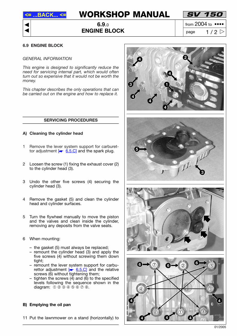
A) Cleaning the cylinder head
1 Remove the lever system support for carburet-tor adjustment [� 6.5.C] and the spark plug.
2 Loosen the screw (1) fixing the exhaust cover (2)to the cylinder head (3).
3 Undo the other five screws (4) securing thecylinder head (3).
4 Remove the gasket (5) and clean the cylinderhead and cylinder surfaces.
5 Turn the flywheel manually to move the pistonand the valves and clean inside the cylinder,removing any deposits from the valve seats.
6 When mounting:
– the gasket (5) must always be replaced;– remount the cylinder head (3) and apply the
five screws (4) without screwing them downtight;
– remount the lever system support for carbu-rettor adjustment [� 6.5.C] and the relativescrews (6) without tightening them;
– tighten the screws (4) and (6) to the specifiedlevels following the sequence shown in thediagram: ➀ ➁ ➂ ➃ ➄ ➅ ➆ ➇.
B) Emptying the oil pan
11 Put the lawnmower on a stand (horizontally) to
SV 150
6.9.0ENGINE BLOCK
��
�� 1 / 2� �
WORKSHOP MANUAL
page
from 2004 to ••••
01/2005
➁➆ ➄
➃
➅ ➀ ➇
➂
4
4
1
2
5
4
3
4
4
3
6 66
4
4 4 4
4

facilitate access to the lower part and drain allthe oil.
12 Remove the oil filling cap (11) and position asuitable container for collecting the oil. Unscrewthe drain plug (12) and let all the oil pour out.
13 When fitting the drain plug (12), check that thegasket underneath is intact and positioned cor-rectly.
C) Removing the engine
21 Empty the tank of fuel [� 6.1.A].
22 Disconnect the throttle cable (21) and theengine brake cable (22).
23 Dismount the cutting assembly and undo the 3screws (23) which are accessible from the bot-tom of the lawnmower.
24 Hold the engine in points with a firm grip,remembering that it weighs approx. 10 kg.
25 When mounting,
– tighten the screws to the specified levels;
– check the efficiency of the engine brake [�6.5.A].
– check that the throttle cable is correctlyadjusted [� 6.7.C]
Tightening torques
4-6 Cylinder head screws ..................... 20-25 Nm12 Oil drain plug .................................. 18-22 Nm23 Engine screws ................................ 20-28 Nm
SV 150
6.9.0ENGINE BLOCK
��
�� 2 / 2� �
WORKSHOP MANUAL
page
from 2004 to ••••
01/2005
23
11
23
23
2122
12