wurth electronics inc. field application engineer …wll.com/us/wp-content/uploads/emiseminar...
TRANSCRIPT

Würth Elektronik eiSos © May/2006 Michael Eckert
Welcome!Inductors & EMC-Ferrites
Basics Basics -- Parts and Parts and ApplicationsApplications
Wurth Electronics Inc.Field Application Engineer
Michael Eckert
Würth Elektronik eiSos © May/2006 Michael Eckert
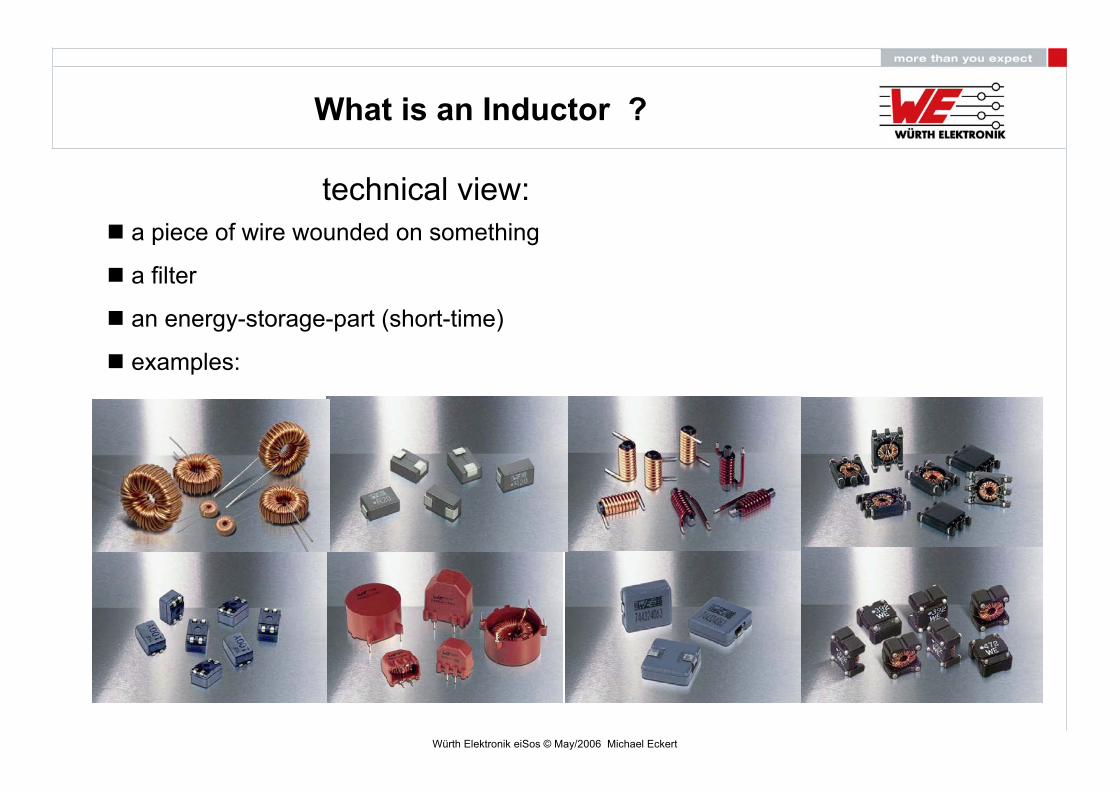
What is an Inductor ?
technical view:a piece of wire wounded on something
a filter
an energy-storage-part (short-time)
examples:
Würth Elektronik eiSos © May/2006 Michael Eckert
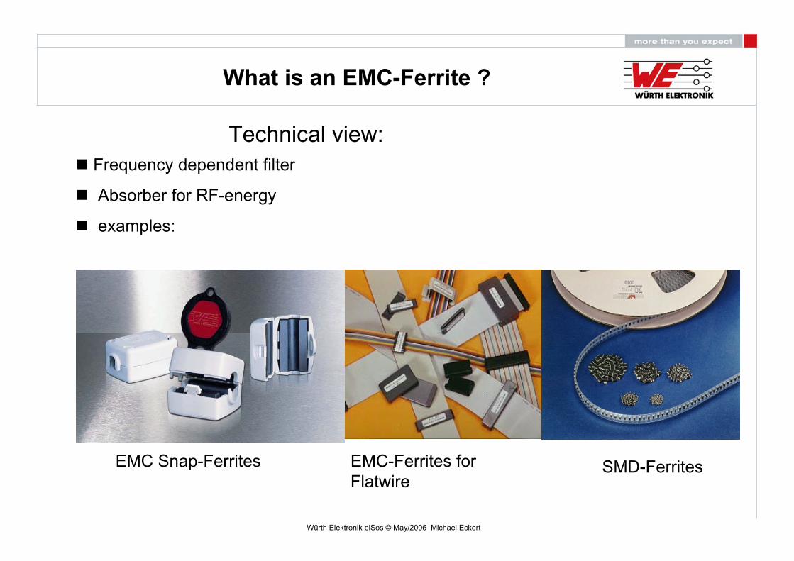
What is an EMC-Ferrite ?
Technical view:Frequency dependent filter
Absorber for RF-energy
examples:
EMC Snap-Ferrites EMC-Ferrites forFlatwire
SMD-Ferrites
Würth Elektronik eiSos © May/2006 Michael Eckert
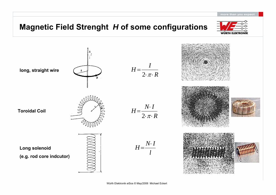
Magnetic Field Strenght H of some configurations
RIH⋅⋅
=π2
RINH⋅⋅⋅
=π2
lINH ⋅
=
long, straight wire
Toroidal Coil
Long solenoid
(e.g. rod core indcutor)
Würth Elektronik eiSos © May/2006 Michael Eckert
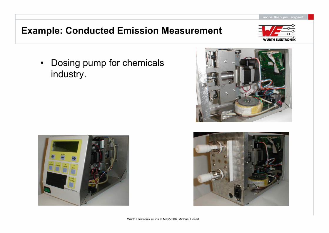
• Dosing pump for chemicalsindustry.
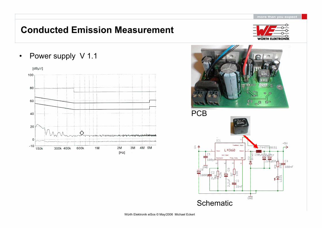
Example: Conducted Emission Measurement

Würth Elektronik eiSos © May/2006 Michael Eckert
• Power supply V 1.0
PCB
Buck Converter ST L4960/2.5A/fs 85-115KHz
Conducted Emission Measurement
Würth Elektronik eiSos © May/2006 Michael Eckert
• Power supply V 1.1
PCB
Schematic
Conducted Emission Measurement
Würth Elektronik eiSos © May/2006 Michael Eckert
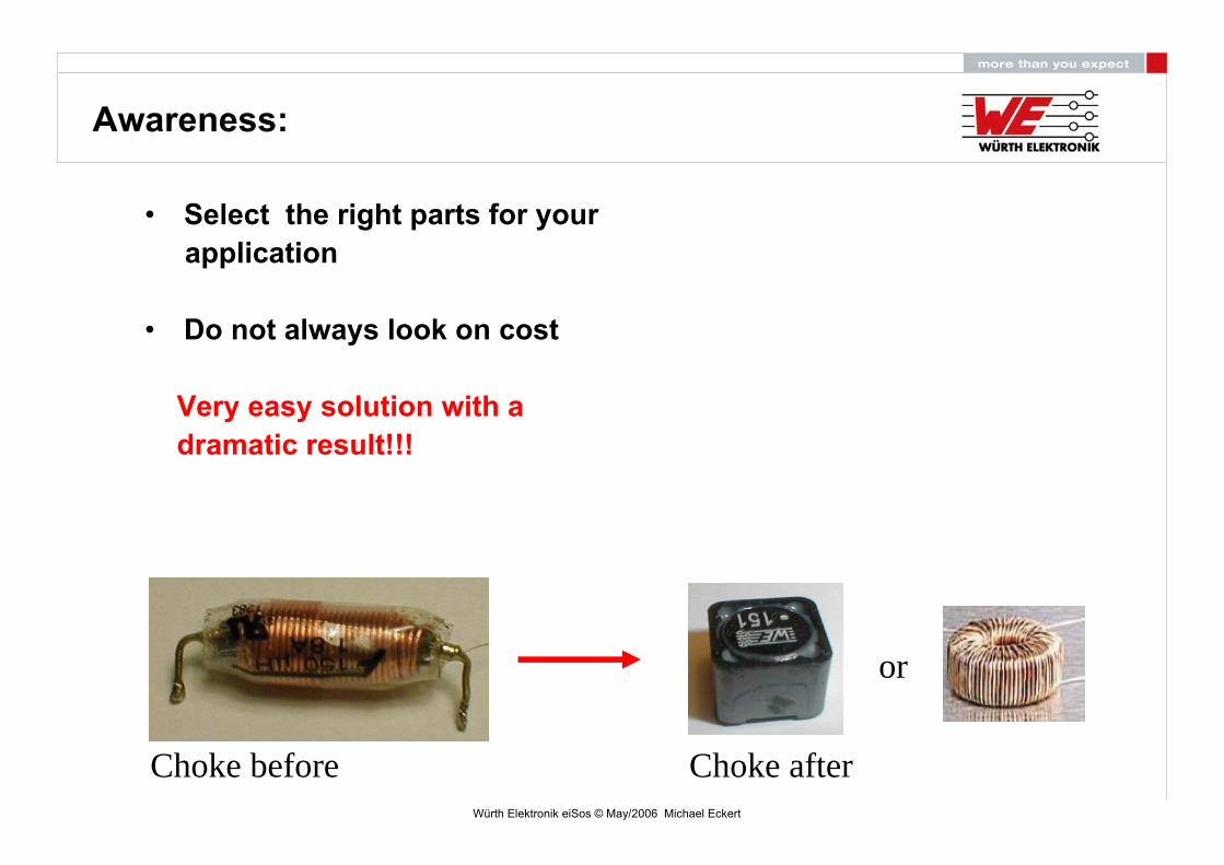
Awareness:
• Select the right parts for yourapplication
• Do not always look on cost
Very easy solution with adramatic result!!!
Choke before Choke after
or

Würth Elektronik eiSos © May/2006 Michael Eckert
What is permeability [ur]?
– Permability (µr): describe the capacity of concentration of the magnetic flux in the material.
typical permeabilities [µr] :
- Iron powder / Superflux : 50 ~ 150
- Nickel Zinc : 40 ~ 1500
- Manganese Zinc : 300 ~ 20000
HB r ⋅⋅= μμ0
Magnetic induction in ferrite:
Non-Linear Function ( µr!)
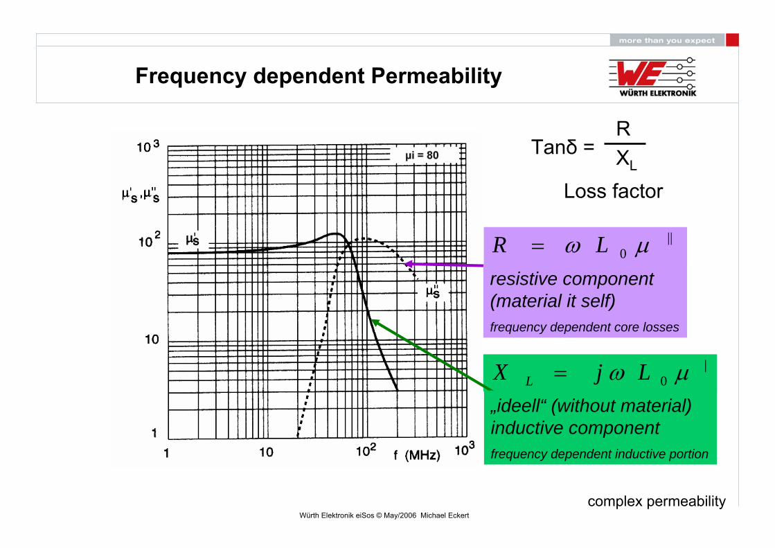
The relative permeability is dependent on frequency……
Würth Elektronik eiSos © May/2006 Michael Eckert
||0 μω LR =
|0 μω LjX L =
resistive component(material it self)frequency dependent core losses
„ideell“ (without material) inductive componentfrequency dependent inductive portion
Tanδ = RXL
Loss factor
Frequency dependent Permeability
complex permeability

Würth Elektronik eiSos © May/2006 Michael Eckert
Measurement of Core Material Properties
Core Material(Fe / MnZn/ NiZn/ …)
Impedance Analyser
RL
XL
Core Material Parameter
XRZ L22 +=
Würth Elektronik eiSos © May/2006 Michael Eckert
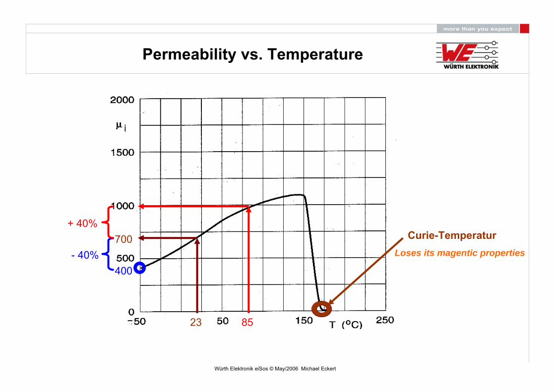
Permeability vs. Temperature
23
700
400- 40%
85
+ 40%Curie-Temperatur
Loses its magentic properties
Würth Elektronik eiSos © May/2006 Michael Eckert
How to find the best part for my application ?
Core Material Comparison

Würth Elektronik eiSos © May/2006 Michael Eckert
When to use which type of material for filtering ?
=> It depends on frequency-range to filter !
Res
istiv
epa
rtof
Impe
danc
e
Würth Elektronik eiSos © May/2006 Michael Eckert
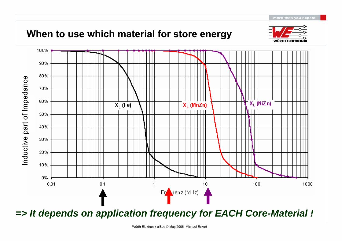
When to use which material for store energy
=> It depends on application frequency for EACH Core-Material !
Indu
ctiv
epa
rtof
Impe
danc
e
Würth Elektronik eiSos © May/2006 Michael Eckert
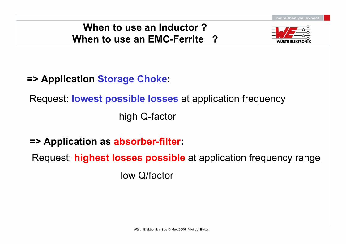
When to use an Inductor ?When to use an EMC-Ferrite ?
=> Application Storage Choke:
Request: lowest possible losses at application frequency
high Q-factor
=> Application as absorber-filter:Request: highest losses possible at application frequency range
low Q/factor

Würth Elektronik eiSos © May/2006 Michael Eckert
Vergleich Güte Ferrit <=> Induktivität
Inductor vs. EMI-Ferrit:
Frequency [MHz]
Q-F
acto
r
Ferrite
Inductor
Comparison Q-Factor: Ferrite vs. Inductor Q = XLR
Losses
Würth Elektronik eiSos © May/2006 Michael Eckert
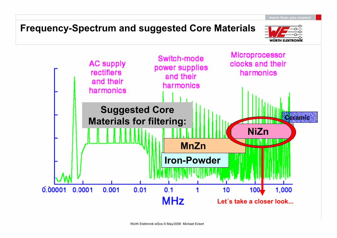
Frequency-Spectrum and suggested Core Materials
Iron-PowderMnZn
NiZn
Suggested CoreMaterials for filtering: Ceramic
Let´s take a closer look...
Würth Elektronik eiSos © May/2006 Michael Eckert
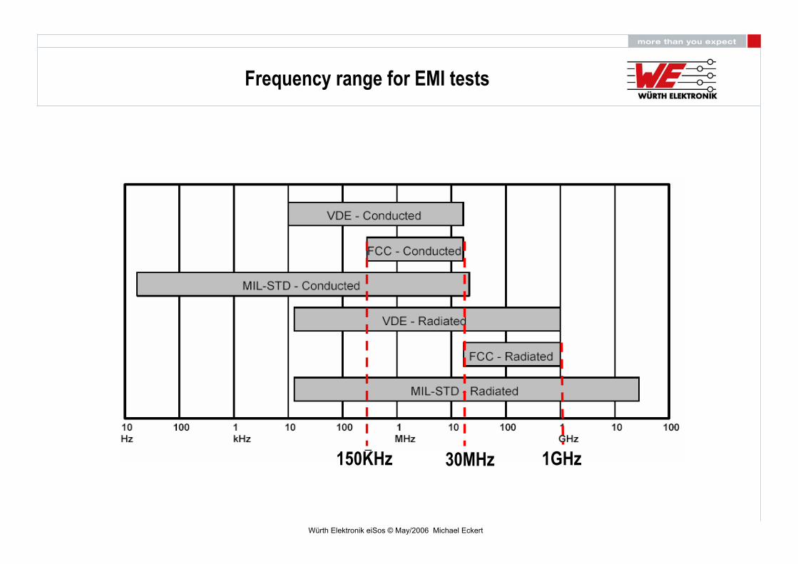
150KHz 30MHz 1GHz
Frequency range for EMI tests

Würth Elektronik eiSos © May/2006 Michael Eckert
Noise SpectrumRadiated Configuration
Conducted Configuration
EUT
150MHz 450MHz
FCC limit lineNoise madeby the device
Overview FCC Tests
Würth Elektronik eiSos © May/2006 Michael Eckert
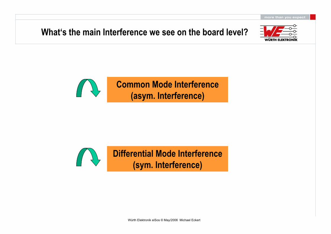
What‘s the main Interference we see on the board level?
Common Mode Interference(asym. Interference)
Differential Mode Interference(sym. Interference)
Würth Elektronik eiSos © May/2006 Michael Eckert
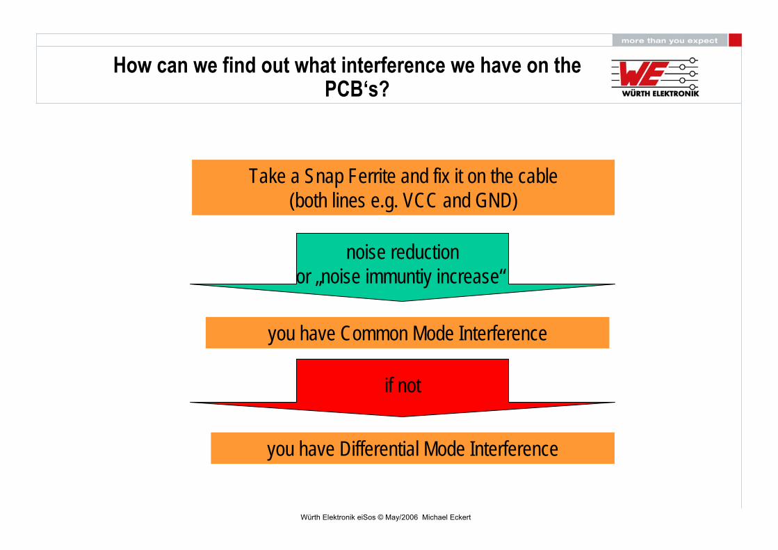
How can we find out what interference we have on thePCB‘s?
Take a Snap Ferrite and fix it on the cable(both lines e.g. VCC and GND)
noise reductionor „noise immuntiy increase“
you have Common Mode Interference
if not
you have Differential Mode Interference

Würth Elektronik eiSos © May/2006 Michael Eckert
Example: Flyback Converter
Appearance of differential noises on the input line of a Flyback Converter
differential interference occurs mainly at lower frequencies
L1
N
PE
Switch (e.g Transistor)
mostly high Cap‘s >100uF; Xc=1/(ωxC)
differential interference
differential interference

Würth Elektronik eiSos © May/2006 Michael Eckert
Example: Flyback Converter
L1
N
PE
parasitic capacities ; in the lower pF (e.g: VCC layer to GND layer( coupling))
Switch (e.g Transistor)
mostly high Cap‘s >100uF; Xc=1/(ωxC)
common mode interference
common mode interference
common mode interference occurs mainly at higherfrequencies
Appearance of common mode noises on the input line of a Flyback Converter
differential interference
Würth Elektronik eiSos © May/2006 Michael Eckert
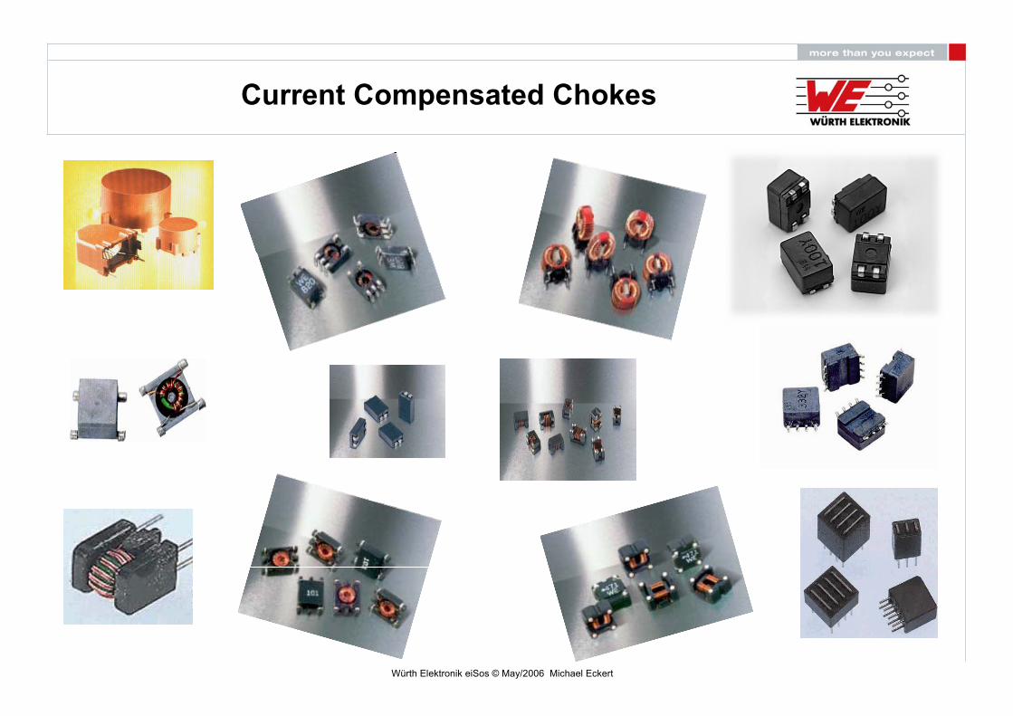
Current Compensated Chokes
Würth Elektronik eiSos © May/2006 Michael Eckert
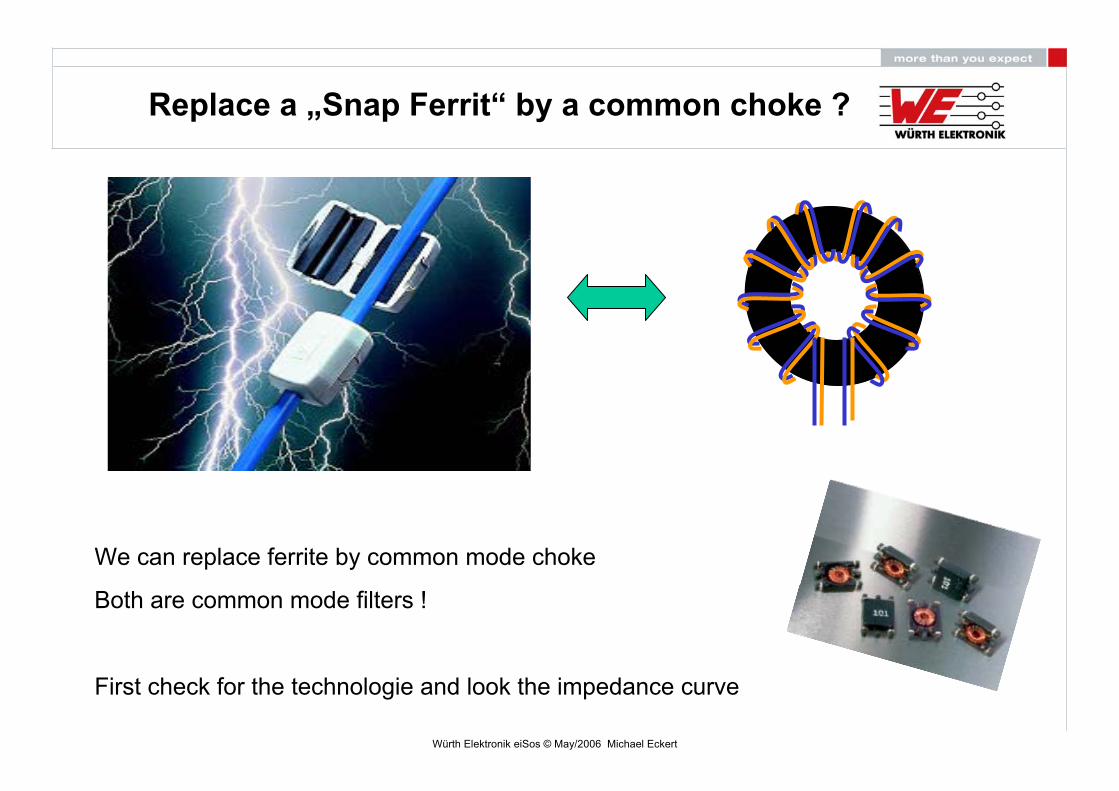
Replace a „Snap Ferrit“ by a common choke ?
We can replace ferrite by common mode choke
Both are common mode filters !
First check for the technologie and look the impedance curve

Würth Elektronik eiSos © May/2006 Michael Eckert
Impedance increase vs. numbers of turnsin
crea
seIm
peda
nce
Fres.-decrease

Würth Elektronik eiSos © May/2006 Michael Eckert
N1
N2
Functionality of a common mode choke:
The operational current (diff. mode) is routed by all relevant conductors through the core(e.g. +/- or L/N). That´s why the magnetic fields of these two conductors compensate eachother to zero => no influence on the wanted signalThe disturbance current flows on both wires in the same direction and generates a magneticfield in the toroidal core => the choke is able to filter unwanted noises.
operational current / wanted signal(diff. mode)
disturbance current(common mode)
Sour
cee.g
. 24A
C Su
pply
Load
5V A
C/DC
Con
verte
r
Würth Elektronik eiSos © May/2006 Michael Eckert
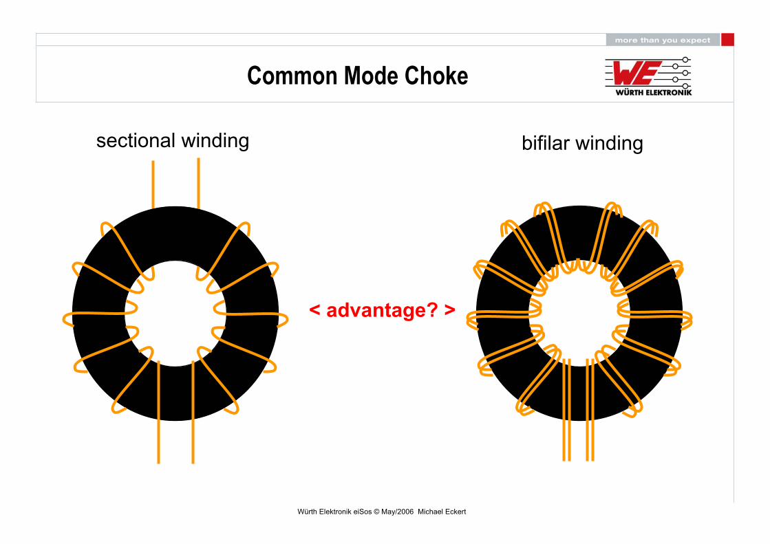
sectional winding bifilar winding
< advantage? >
Common Mode Choke
Würth Elektronik eiSos © May/2006 Michael Eckert
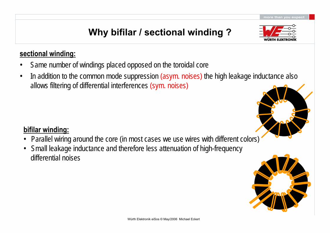
Why bifilar / sectional winding ?
sectional winding:• Same number of windings placed opposed on the toroidal core• In addition to the common mode suppression (asym. noises) the high leakage inductance also
allows filtering of differential interferences (sym. noises)
bifilar winding:• Parallel wiring around the core (in most cases we use wires with different colors)• Small leakage inductance and therefore less attenuation of high-frequency
differential noises

Würth Elektronik eiSos © May/2006 Michael Eckert
For example: WE-SL2 744227SCommon Mode suppression
Differential Mode suppressionis high!
Sectional winding:
ATTENTION:SECTIONELL WINDING MUST BEUSED ON MAIN-POWER SUPPLY !

Würth Elektronik eiSos © May/2006 Michael Eckert
Bifilar winding vs. Sectional winding
For example: WE-SL2 744227Common Mode suppression
Differential Mode suppressionis low!
Differential Mode S-Type
interference(Common Mode )
signal (Differential)
Würth Elektronik eiSos © May/2006 Michael Eckert
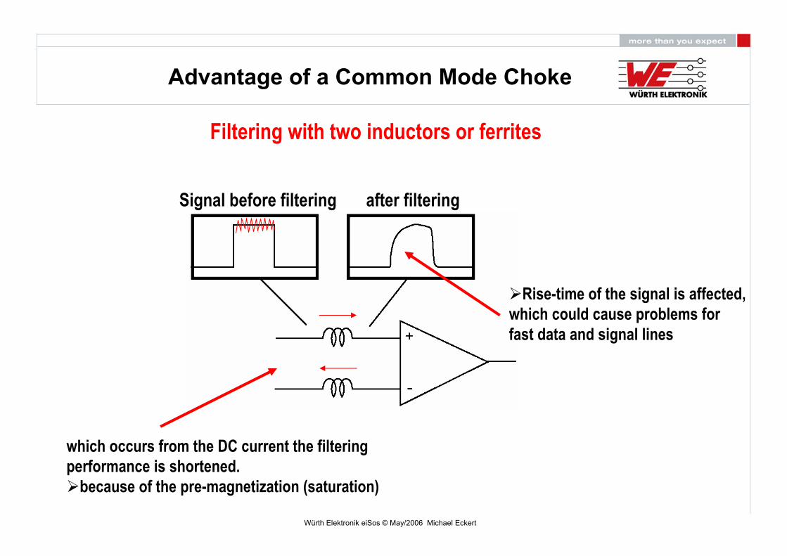
Advantage of a Common Mode Choke
Filtering with two inductors or ferrites
Signal before filtering after filtering
Rise-time of the signal is affected,which could cause problems forfast data and signal lines
which occurs from the DC current the filteringperformance is shortened.
because of the pre-magnetization (saturation)

Würth Elektronik eiSos © May/2006 Michael Eckert
Filtering with a Common Mode Choke
Signal before filtering after filtering
no affect on the signal rise-time, because of magnetic field compensation
no influence of the wanted signal(the two windings are magneticallycoupled)
no pre-magnetization (saturation) occurs from the DC current, because of magnetic coupling
much better performance vs. two separate inductors or ferrites
Advantage of a Common Mode Choke
Würth Elektronik eiSos © May/2006 Michael Eckert
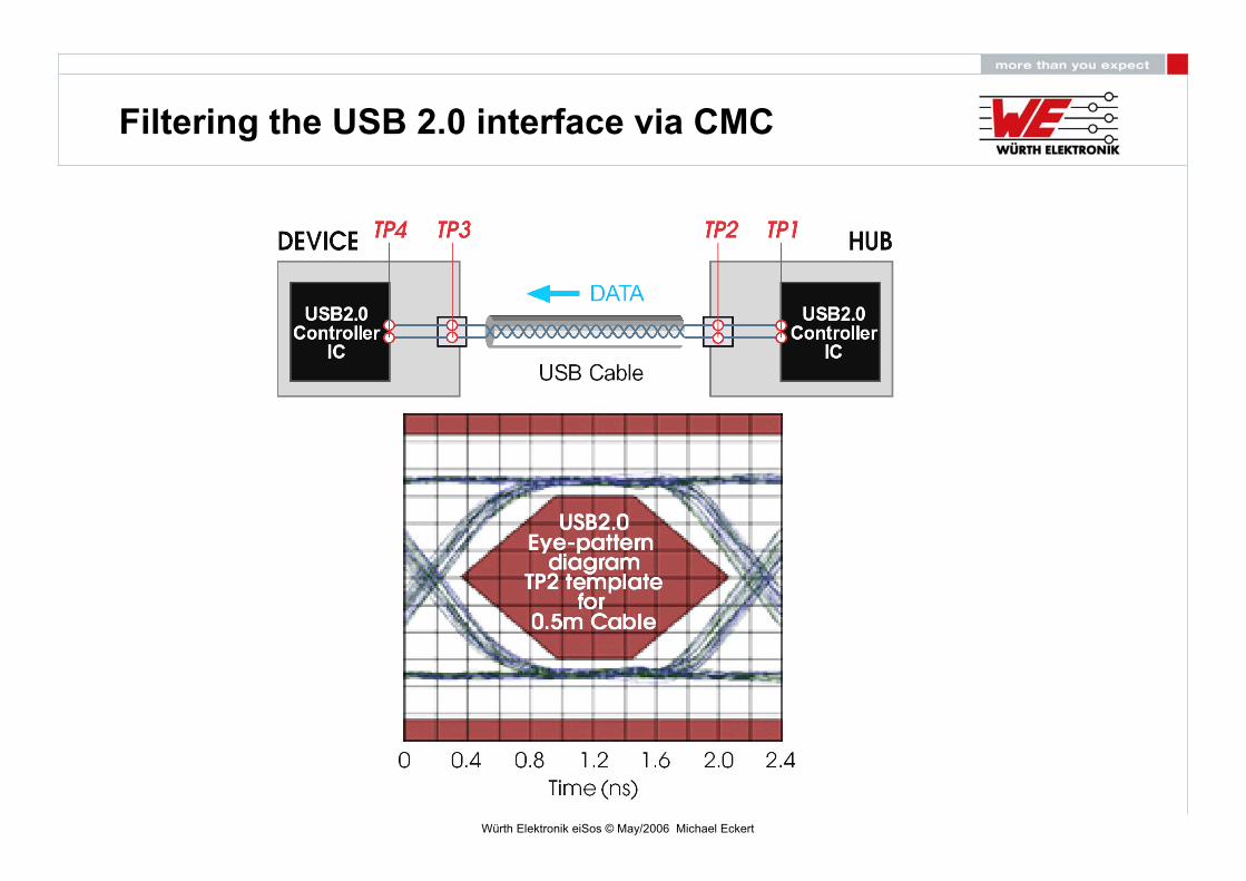
Filtering the USB 2.0 interface via CMC

Würth Elektronik eiSos © May/2006 Michael Eckert
USB 2.0 Filtering via WE-CNSW
measurement point TP2
EMI-filter EMI-filter
90 Ohm @ 100 MHz C.M. 600 Ohm @ 100 MHz C.M. WE-CBF 20 Ohm @ 240 MHz D.M. 40 Ohm @ 240 MHz D.M. 120 Ohm @ 100 MHz
Würth Elektronik eiSos © May/2006 Michael Eckert
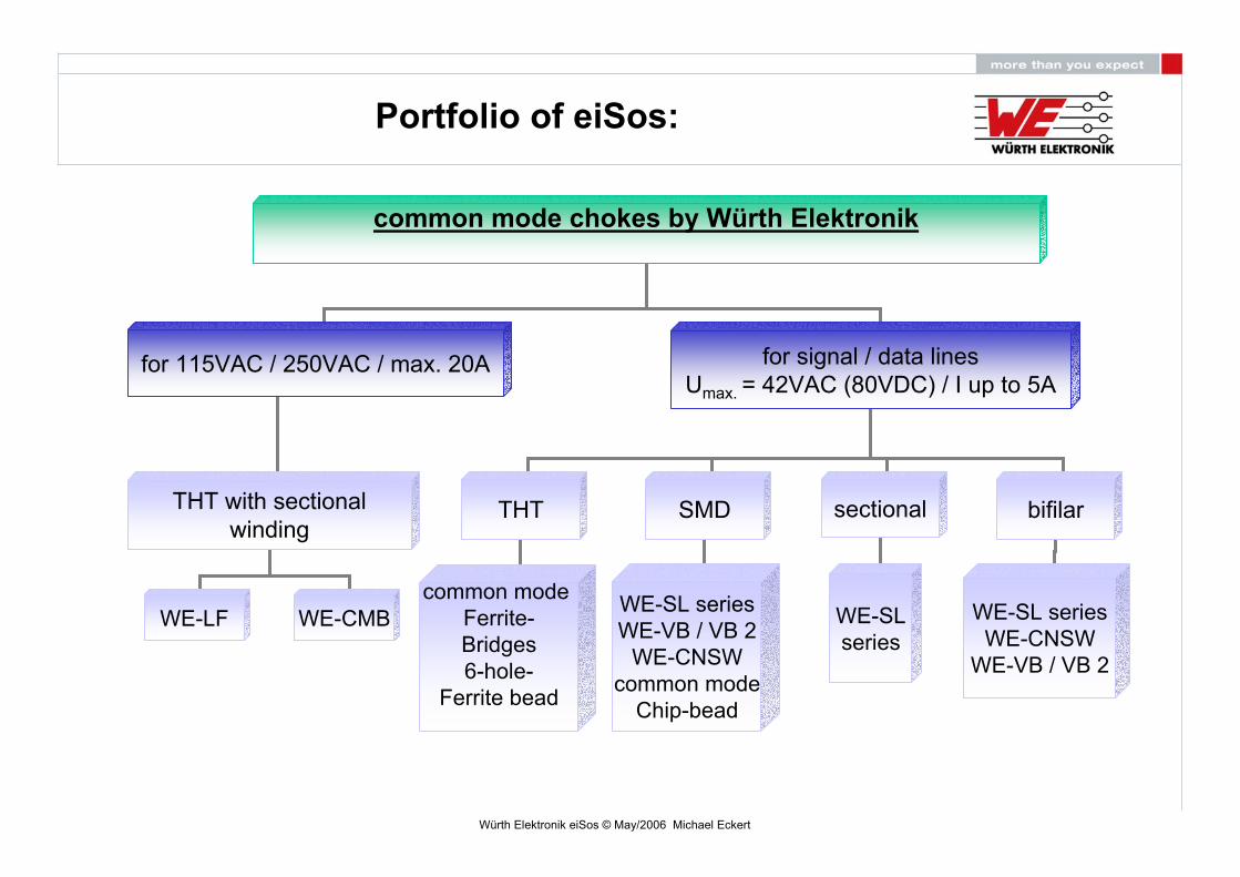
Portfolio of eiSos:
common mode chokes by Würth Elektronik
for 115VAC / 250VAC / max. 20A for signal / data linesUmax. = 42VAC (80VDC) / I up to 5A
THT with sectionalwinding
WE-LF WE-CMB
THT SMD sectional bifilar
common mode Ferrite-Bridges6-hole-
Ferrite bead
WE-SL seriesWE-VB / VB 2
WE-CNSWcommon mode
Chip-bead
WE-SLseries
WE-SL seriesWE-CNSW
WE-VB / VB 2
Würth Elektronik eiSos © May/2006 Michael Eckert
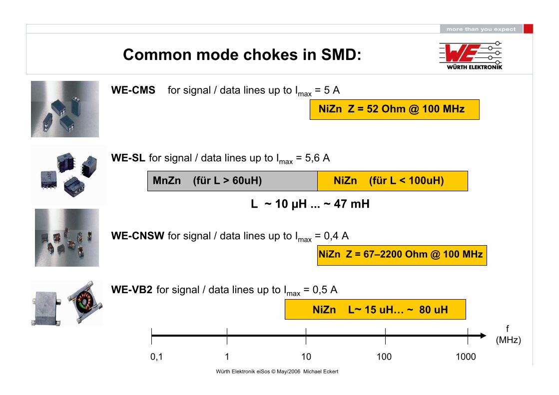
Common mode chokes in SMD:
WE-CNSWNiZn Z = 67–2200 Ohm @ 100 MHz
NiZn (für L < 100uH)
WE-SL
WE-CMS
for signal / data lines up to Imax = 0,4 A
for signal / data lines up to Imax = 5,6 A
for signal / data lines up to Imax = 5 A
WE-VB2
NiZn L~ 15 uH… ~ 80 uH
for signal / data lines up to Imax = 0,5 A
NiZn Z = 52 Ohm @ 100 MHz
MnZn (für L > 60uH)
L ~ 10 µH ... ~ 47 mH
f (MHz)
10001001010,1
Würth Elektronik eiSos © May/2006 Michael Eckert
f (MHz)
10001001010,1
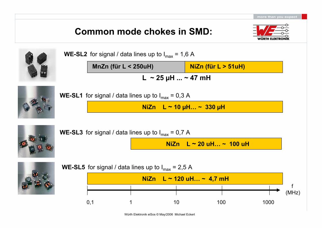
WE-SL3
NiZn L ~ 20 uH… ~ 100 uH
NiZn L ~ 10 µH… ~ 330 µH
WE-SL1
WE-SL2
MnZn (für L < 250uH)
for signal / data lines up to Imax = 0,7 A
for signal / data lines up to Imax = 0,3 A
for signal / data lines up to Imax = 1,6 A
WE-SL5
NiZn L ~ 120 uH… ~ 4,7 mH
for signal / data lines up to Imax = 2,5 A
NiZn (für L > 51uH)
L ~ 25 µH ... ~ 47 mH
Common mode chokes in SMD:
Würth Elektronik eiSos © May/2006 Michael Eckert
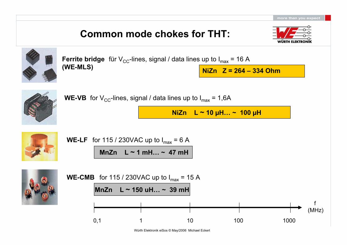
Common mode chokes for THT:
f (MHz)
10001001010,1
WE-LF
MnZn L ~ 1 mH… ~ 47 mH
NiZn L ~ 10 µH… ~ 100 µH
WE-VB
Ferrite bridge(WE-MLS)
for 115 / 230VAC up to Imax = 6 A
for VCC-lines, signal / data lines up to Imax = 1,6A
für VCC-lines, signal / data lines up to Imax = 16 A
WE-CMB for 115 / 230VAC up to Imax = 15 A
MnZn L ~ 150 uH… ~ 39 mH
NiZn Z = 264 – 334 Ohm
Würth Elektronik eiSos © May/2006 Michael Eckert
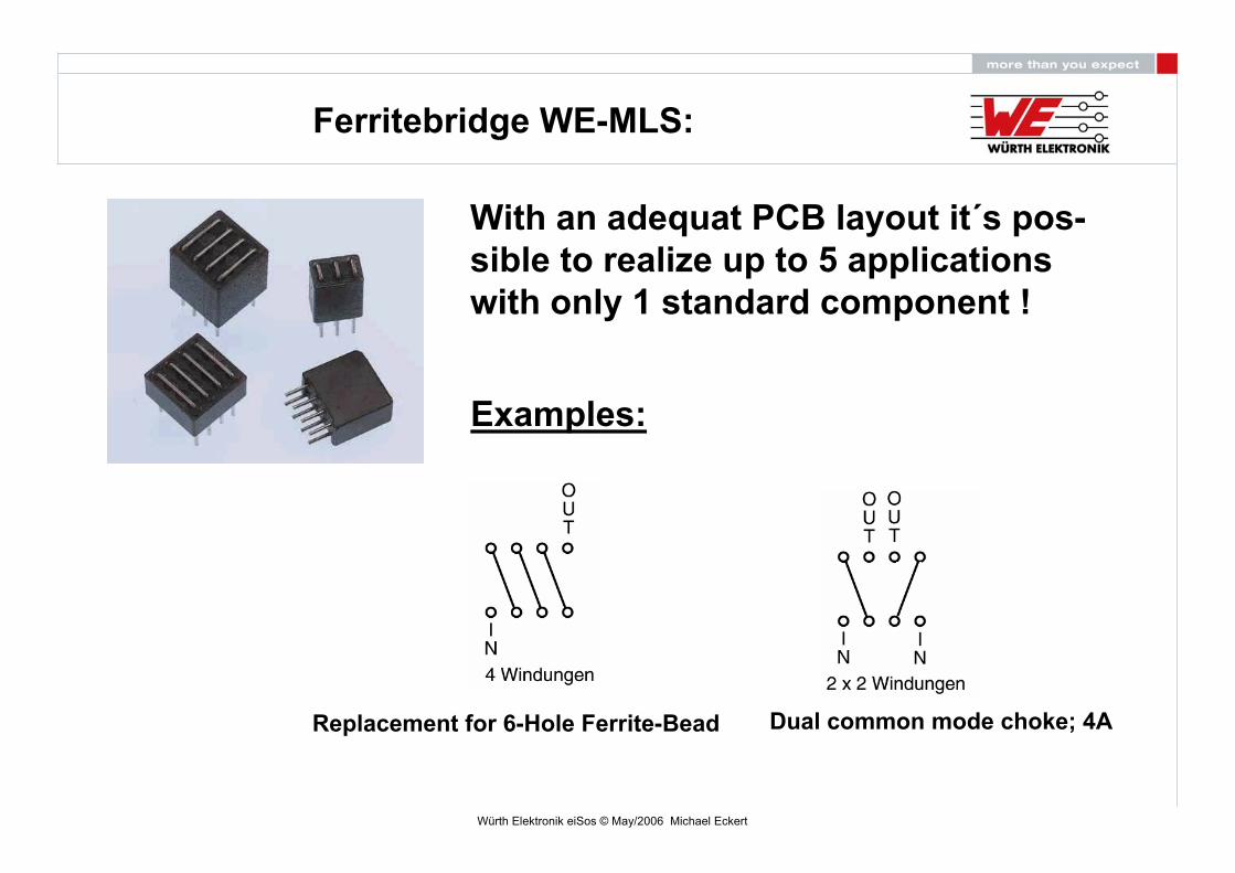
Ferritebridge WE-MLS:
With an adequat PCB layout it´s pos-sible to realize up to 5 applicationswith only 1 standard component !
Replacement for 6-Hole Ferrite-Bead Dual common mode choke; 4A
Examples:
Würth Elektronik eiSos © May/2006 Michael Eckert
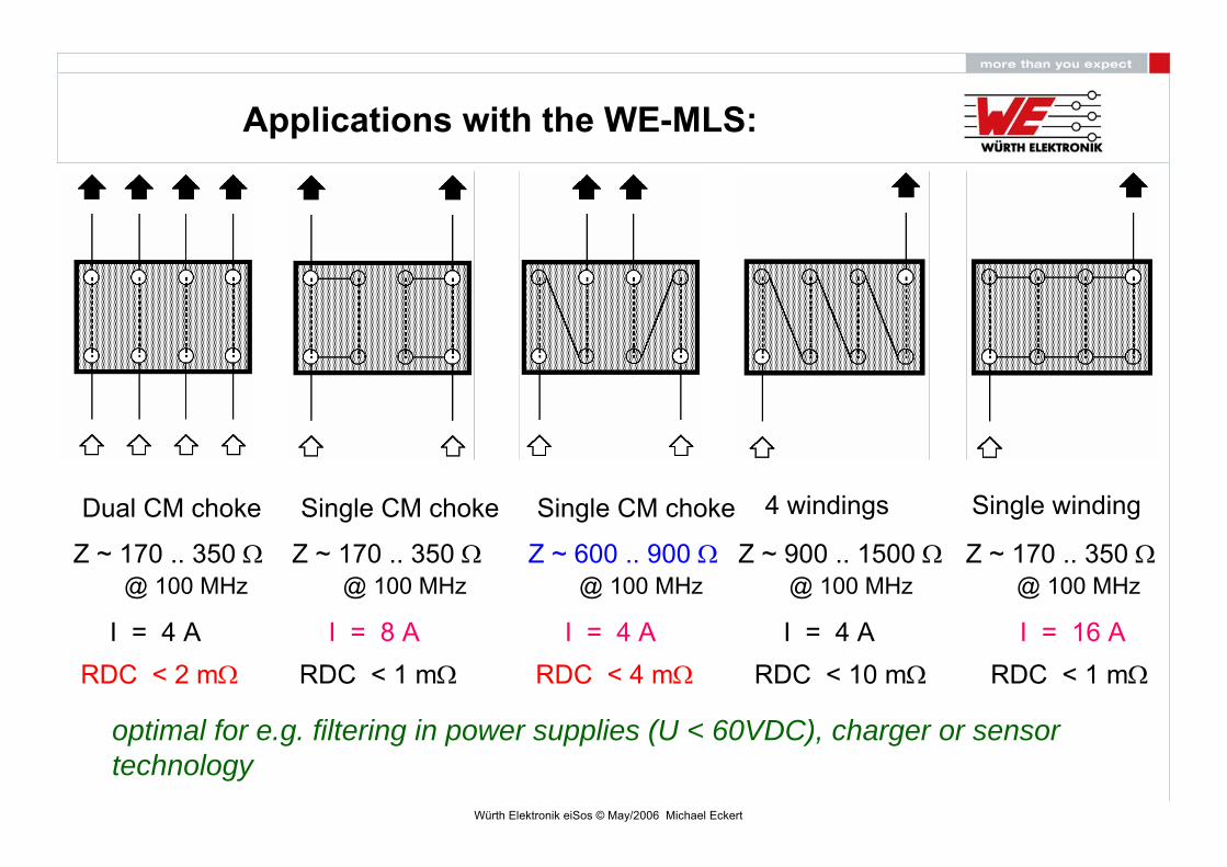
Applications with the WE-MLS:
Dual CM choke
Z ~ 170 .. 350 Ω@ 100 MHz
I = 4 ARDC < 2 mΩ
Single CM choke
Z ~ 170 .. 350 Ω@ 100 MHz
I = 8 ARDC < 1 mΩ
Single CM choke
Z ~ 600 .. 900 Ω@ 100 MHz
I = 4 ARDC < 4 mΩ
4 windings
Z ~ 900 .. 1500 Ω@ 100 MHz
I = 4 ARDC < 10 mΩ
Z ~ 170 .. 350 Ω@ 100 MHz
RDC < 1 mΩ
Single winding
I = 16 A
optimal for e.g. filtering in power supplies (U < 60VDC), charger or sensortechnology
Würth Elektronik eiSos © May/2006 Michael Eckert
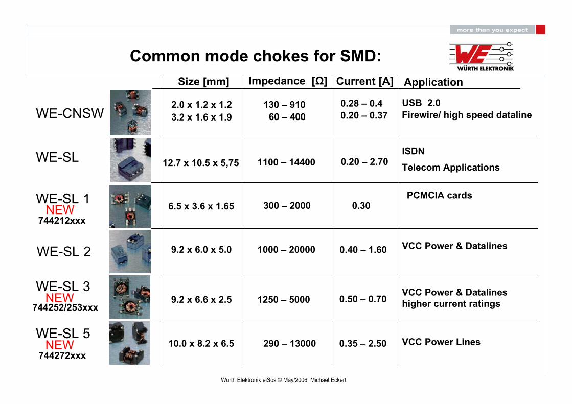
WE-SL
WE-SL 1
WE-SL 2
WE-SL 3
WE-SL 5
WE-CNSW
Size [mm] Impedance [Ω] Current [A]
2.0 x 1.2 x 1.23.2 x 1.6 x 1.9
12.7 x 10.5 x 5,75
9.2 x 6.0 x 5.0
6.5 x 3.6 x 1.65
9.2 x 6.6 x 2.5
10.0 x 8.2 x 6.5
Application
0.28 – 0.40.20 – 0.37
0.20 – 2.70
0.30
0.40 – 1.60
0.50 – 0.70
0.35 – 2.50
130 – 91060 – 400
1100 – 14400
300 – 2000
1250 – 5000
290 – 13000
1000 – 20000
USB 2.0Firewire/ high speed dataline
VCC Power & Datalines
VCC Power & Datalineshigher current ratings
ISDNTelecom Applications
VCC Power Lines
744212xxxNEW
NEW744252/253xxx
NEW744272xxx
PCMCIA cards
Common mode chokes for SMD:
Würth Elektronik eiSos © May/2006 Michael Eckert
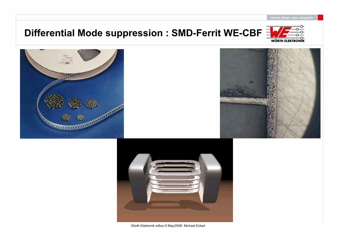
Differential Mode suppression : SMD-Ferrit WE-CBF
Würth Elektronik eiSos © May/2006 Michael Eckert
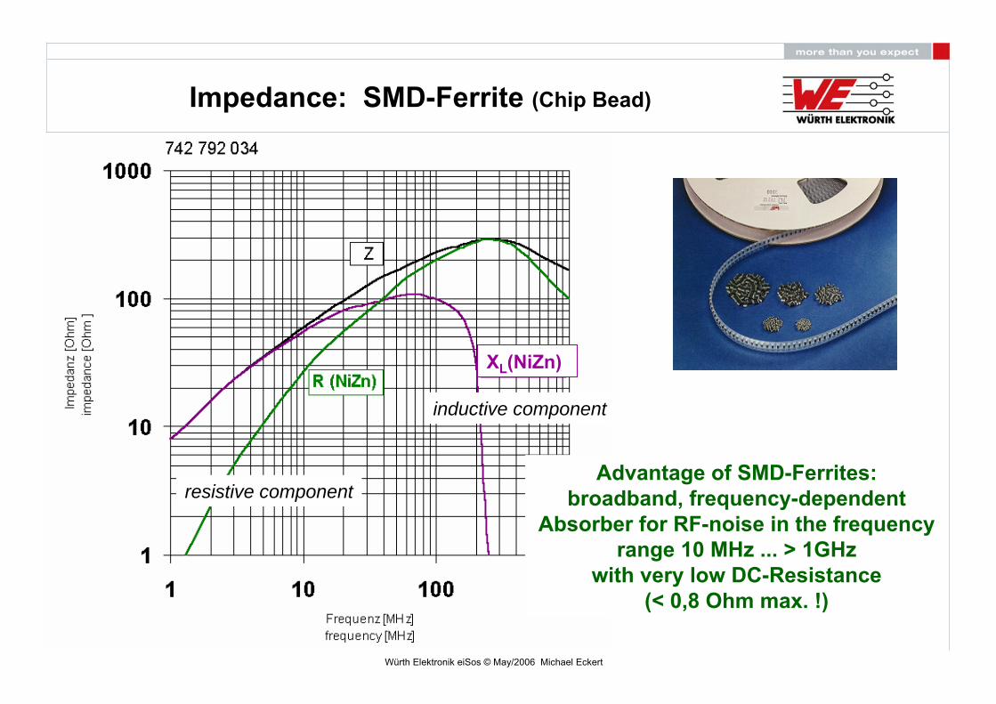
Impedance: SMD-Ferrite (Chip Bead)
XL(NiZn)
Advantage of SMD-Ferrites:broadband, frequency-dependent
Absorber for RF-noise in the frequencyrange 10 MHz ... > 1GHz
with very low DC-Resistance(< 0,8 Ohm max. !)
resistive component
inductive component

Würth Elektronik eiSos © May/2006 Michael Eckert
Which impedance do we need ?
0
10
20
30
40
50
60
Level [dBµV/m]
30M 40M 50M 70M 100M 200M 300M 400M 600M 1G
Frequency [Hz]

Würth Elektronik eiSos © May/2006 Michael Eckert
Insertion Loss Model
Equivalent circuit of Filter
Equivalent circuitof source
Equivalent circuit of system impedance
)(log20 dBinZZ
ZZZABA
BFA
+++
=Insertion Loss =>
Würth Elektronik eiSos © May/2006 Michael Eckert
Simulation Model Cap
Simulation Model Fer.
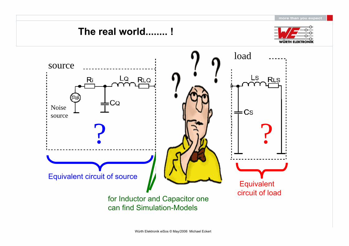
The real world........ !
Equivalent Circuit of Filter-ComponentsEquivalent circuit of source
Equivalentcircuit of load
for Inductor and Capacitor onecan find Simulation-Models
? ?
source
Noisesource
load
Würth Elektronik eiSos © May/2006 Michael Eckert
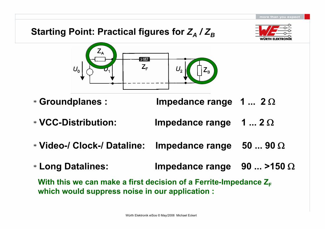
Starting Point: Practical figures for ZA / ZB
* Groundplanes : Impedance range 1 ... 2 Ω
* VCC-Distribution: Impedance range 1 ... 2 Ω
* Video-/ Clock-/ Dataline: Impedance range 50 ... 90 Ω
* Long Datalines: Impedance range 90 ... >150 ΩWith this we can make a first decision of a Ferrite-Impedance ZFwhich would suppress noise in our application :
Würth Elektronik eiSos © May/2006 Michael Eckert
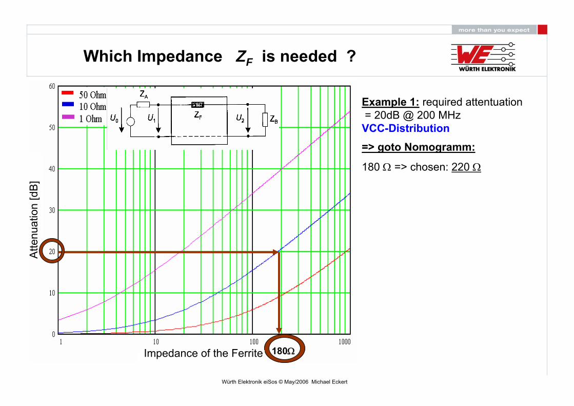
Which Impedance ZF is needed ?
Example 1: required attentuation= 20dB @ 200 MHz VCC-Distribution
180Ω
=> goto Nomogramm:
180 Ω => chosen: 220 Ω
Impedance of the Ferrite
Atte
nuat
ion
[dB
]

Würth Elektronik eiSos © May/2006 Michael Eckert
Insertion Loss vs. Impedance of Source/ Load (ZA / ZB)
A = -32 dB max.with ZA = ZB = 10 Ω = constant
A = -18 dB max.with ZA = ZB = 50 Ω = constant
A = - 8 dB max.with ZA = ZB = 200 Ω = constant
A = - 3 dB max.with ZA = ZB = 1000 Ω = constant
with ZA = ZB = 5000 Ω =constantno effect in filtering !
SMD-Ferrite ZF = 600 Ohm @ 100 MHz
Frequency (Hz)
Inse
rtio
n Lo
ss(d
B)

Würth Elektronik eiSos © May/2006 Michael Eckert
Simulation with RF Sim 99 or SWITCHER CAD III
Demostrationa) via equivalent circuit
b) via S-Parameters
)(log20 dBinZZ
ZZZABA
BFA
+++
=Insertion Loss =>
S-parameters are available on our homepage

Würth Elektronik eiSos © May/2006 Michael Eckert
SMD-Ferrite listed in LTSpice/SwitcherCADIII
Freeware !Download www.linear.com_
Würth Elektronik eiSos © May/2006 Michael Eckert
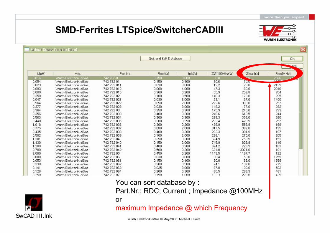
SMD-Ferrites LTSpice/SwitcherCADIII
You can sort database by :Part.Nr.; RDC; Current ; Impedance @100MHz ormaximum Impedance @ which Frequency
SwCAD III.lnk
Würth Elektronik eiSos © May/2006 Michael Eckert
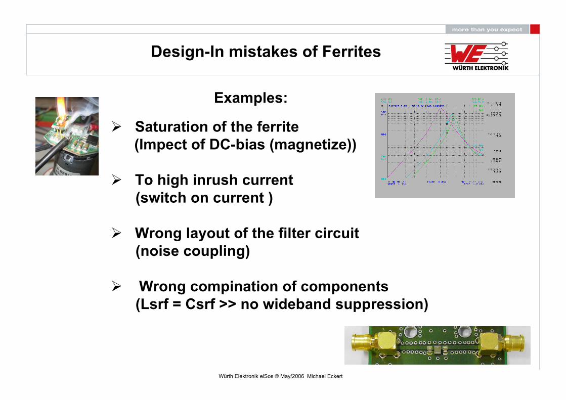
Saturation of the ferrite(Impect of DC-bias (magnetize))
To high inrush current(switch on current )
Wrong layout of the filter circuit(noise coupling)
Wrong compination of components(Lsrf = Csrf >> no wideband suppression)
Examples:
Design-In mistakes of Ferrites

Würth Elektronik eiSos © May/2006 Michael Eckert
Impect of DC-bias (pre-magnetization (saturation)
800Ω@100MHZ (0ADC)
420Ω@100MHZ (1,7ADC)
230Ω@100MHZ (3ADC)
742792515 (3A typ)
Design-In mistakes of Ferrites

Würth Elektronik eiSos © May/2006 Michael Eckert
Impect of DC-bias (pre-magnetization (saturation)
Würth Elektronik eiSos © May/2006 Michael Eckert
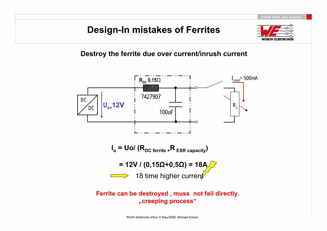
Ferrite can be destroyed , muss not fail directly.„creeping process“
Io = Uo/ (RDC ferrite +R ESR capacity)
= 12V / (0,15Ω+0,5Ω) = 18A18 time higher current
Destroy the ferrite due over current/inrush current
DCDC RL
Iconst= 500mA
7427907Uo=12V
100uF
RDC 0,15Ω
Design-In mistakes of Ferrites

Würth Elektronik eiSos © May/2006 Michael Eckert
Design-In mistakes of Ferrites
Destroy the ferrite due switch on current(no current limitation was done by the customer)
Würth Elektronik eiSos © May/2006 Michael Eckert
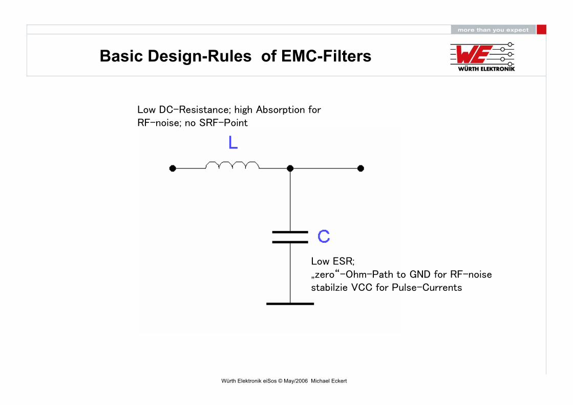
Basic Design-Rules of EMC-Filters
Low DC-Resistance; high Absorption forRF-noise; no SRF-Point
Low ESR; „zero“-Ohm-Path to GND for RF-noisestabilzie VCC for Pulse-Currents
Würth Elektronik eiSos © May/2006 Michael Eckert
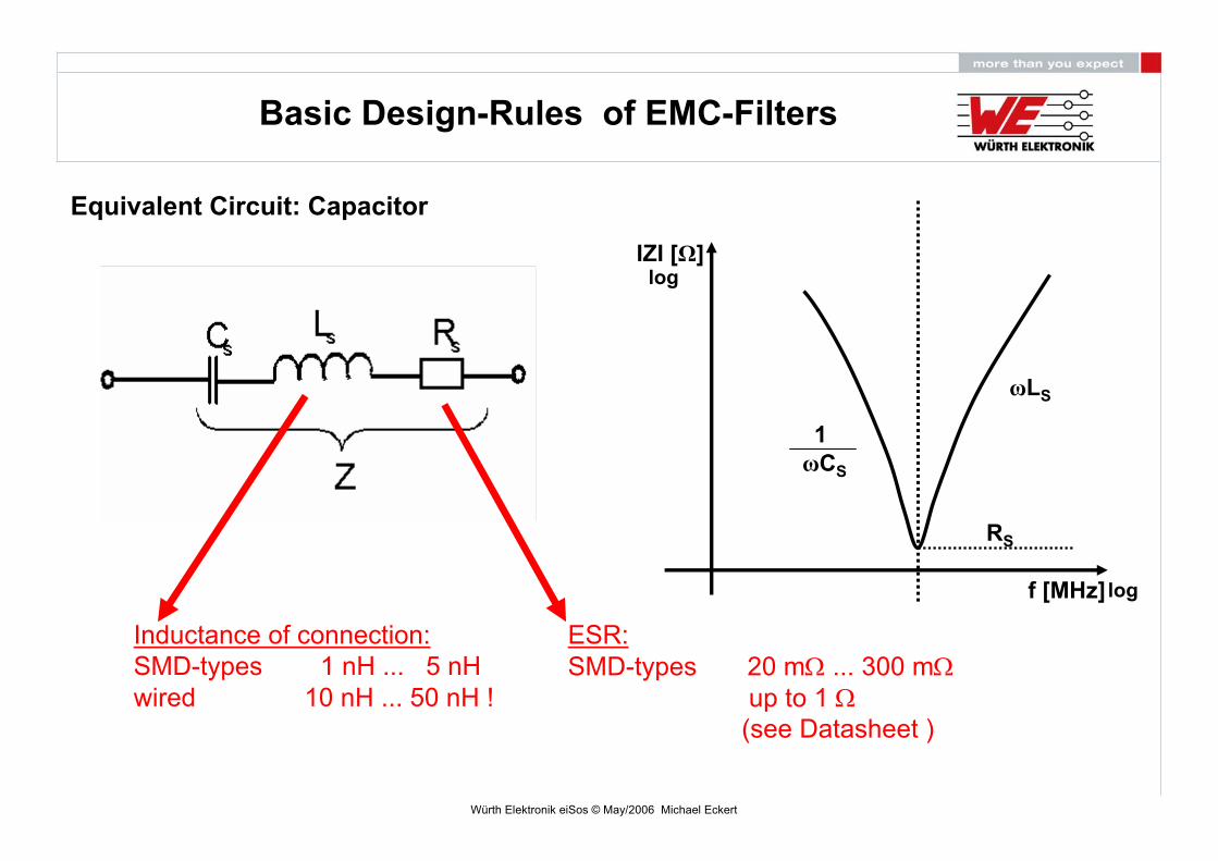
Inductance of connection:SMD-types 1 nH ... 5 nHwired 10 nH ... 50 nH !
ESR:SMD-types 20 mΩ ... 300 mΩ
up to 1 Ω(see Datasheet )
Equivalent Circuit: Capacitor
Basic Design-Rules of EMC-Filters
IZI [Ω]
f [MHz]
ωLS
ωCS
1
RS
log
log
Würth Elektronik eiSos © May/2006 Michael Eckert
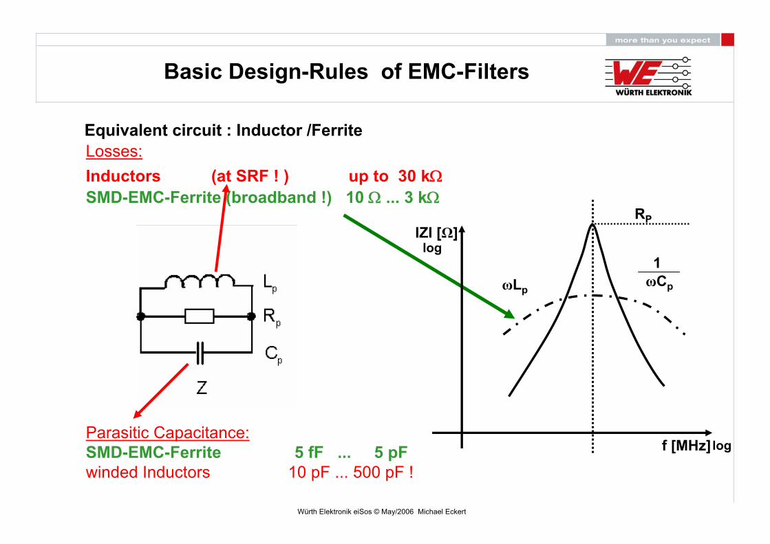
Equivalent circuit : Inductor /Ferrite
Parasitic Capacitance:SMD-EMC-Ferrite 5 fF ... 5 pFwinded Inductors 10 pF ... 500 pF !
Losses:Inductors (at SRF ! ) up to 30 kΩSMD-EMC-Ferrite (broadband !) 10 Ω ... 3 kΩ
Basic Design-Rules of EMC-Filters
IZI [Ω]
f [MHz]
ωLpωCp
1
RP
log
log

Würth Elektronik eiSos © May/2006 Michael Eckert
1 mm ~ 1nH
1 via ~ 0.5 nH0.5 nH @ 100 MHz = 0.314 Ω
0.5 nH @ 1 GHz = 3.14 Ω !
Zges: ESR+Lr (2nH)+Lvia(0,5nH)
100nF= 0,2Ω+1,2Ω+0,3Ω= 1,7Ω@100MHz
Basic Design-Rules of EMC-Filters
Size: 0603/X7R

Würth Elektronik eiSos © May/2006 Michael Eckert
LC-Lowpassfilter Layout Lowpassfilter
Why will this Filter not work properly at RF-Frequencies ?
Ground-Level
Grounding / Layout

Würth Elektronik eiSos © May/2006 Michael Eckert
Grounding / Layout
Inductive coupling
Capacitive coupling
Bypass fornoise
too long tracks
Contraction for RF
more vias to GND= low impedance
Connection to Case
bad solution optimized
Würth Elektronik eiSos © May/2006 Michael Eckert
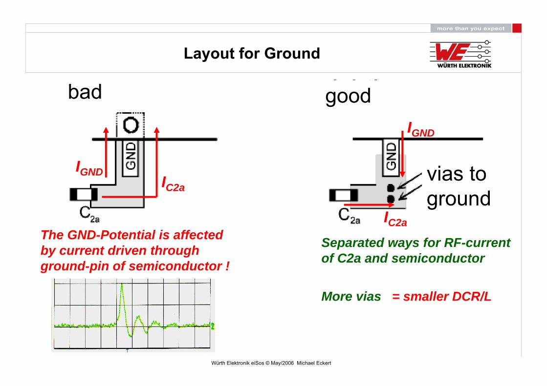
Layout for Ground
IC2a
IGND
The GND-Potential is affectedby current driven throughground-pin of semiconductor !
IGND
IC2a
Separated ways for RF-currentof C2a and semiconductor
More vias = smaller DCR/L
bad good
vias to ground

Würth Elektronik eiSos © May/2006 Michael Eckert
Impedance vs. Frequency of Capacitors
3/4 parts are needed to,,,,,,,,,,,, !!
Würth Elektronik eiSos © May/2006 Michael Eckert
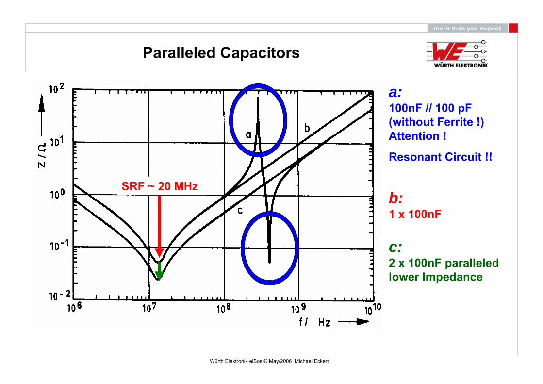
Paralleled Capacitors
a:100nF // 100 pF(without Ferrite !)Attention !
Resonant Circuit !!
b:1 x 100nF
c:2 x 100nF paralleledlower Impedance
SRF ~ 20 MHz
Würth Elektronik eiSos © May/2006 Michael Eckert
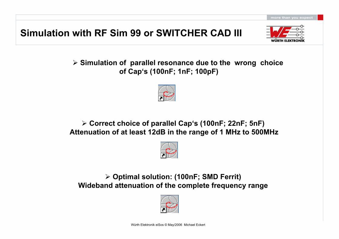
Simulation of parallel resonance due to the wrong choiceof Cap‘s (100nF; 1nF; 100pF)
Simulation with RF Sim 99 or SWITCHER CAD III
Correct choice of parallel Cap‘s (100nF; 22nF; 5nF)Attenuation of at least 12dB in the range of 1 MHz to 500MHz
Optimal solution: (100nF; SMD Ferrit)Wideband attenuation of the complete frequency range
Würth Elektronik eiSos © May/2006 Michael Eckert
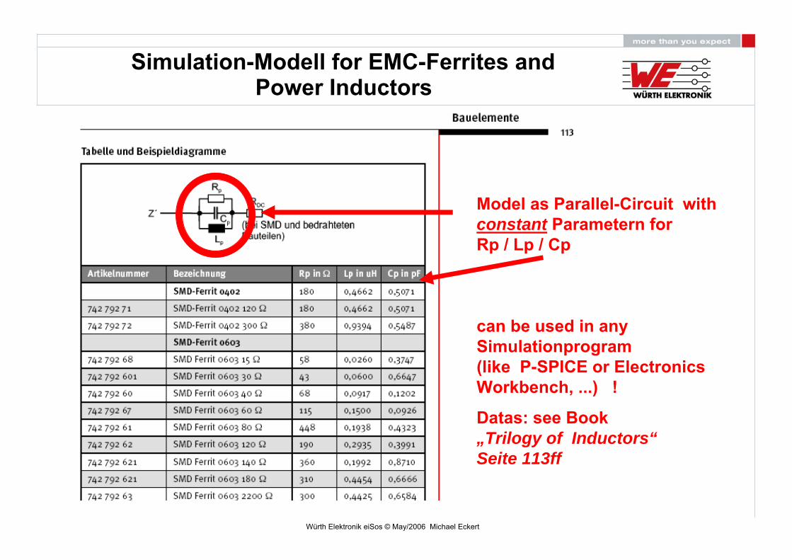
Simulation-Modell for EMC-Ferrites and
Model as Parallel-Circuit withconstant Parametern forRp / Lp / Cp
can be used in anySimulationprogram(like P-SPICE or Electronics Workbench, ...) !
Datas: see Book„Trilogy of Inductors“Seite 113ff
Power Inductors
Würth Elektronik eiSos © May/2006 Michael Eckert
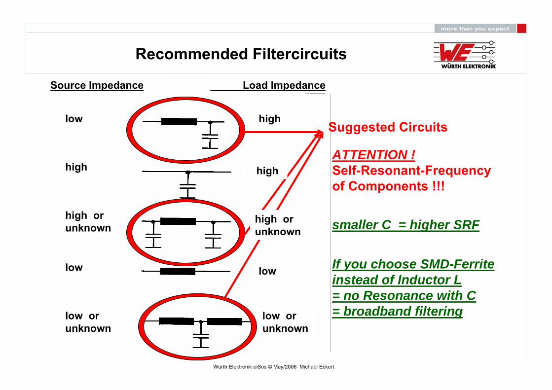
Recommended Filtercircuits
Suggested Circuits
ATTENTION !Self-Resonant-Frequencyof Components !!!
smaller C = higher SRF
If you choose SMD-Ferrite instead of Inductor L = no Resonance with C = broadband filtering
Source Impedance Load Impedance
low
low low
high
high
high
high orunknown
low orunknown
high orunknown
low orunknown

Würth Elektronik eiSos © May/2006 Michael Eckert
Noise source
Source: USB/Battery
DC-DC-Converter LT13043,3V to 5V
PD Typ M 22uH7447779122
LC-Filter
Pi-Filter
Crystal Oscillators(25MHz and 100MHz)to generate the noisespectrum
f
A
Würth Elektronik eiSos © May/2006 Michael Eckert
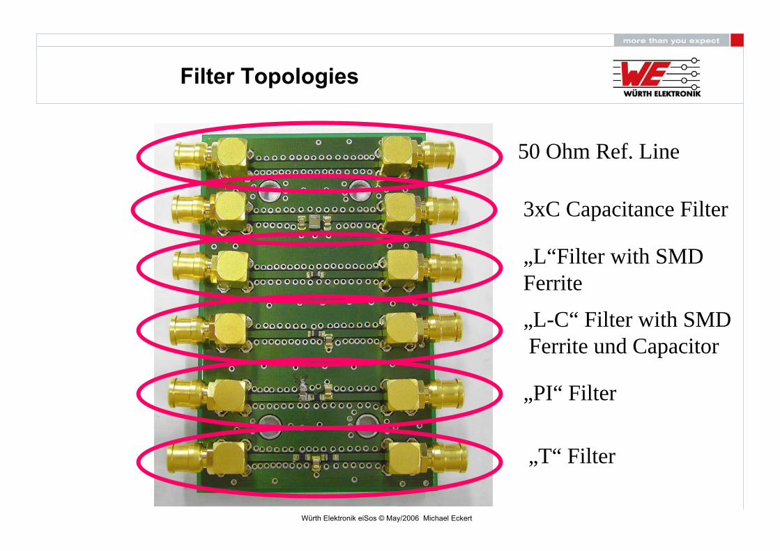
Filter Topologies
50 Ohm Ref. Line
3xC Capacitance Filter
„L“Filter with SMD Ferrite
„L-C“ Filter with SMDFerrite und Capacitor
„PI“ Filter
„T“ Filter

Würth Elektronik eiSos © May/2006 Michael Eckert
The „L“ Ferrite –Filter
Würth Elektronik eiSos © May/2006 Michael Eckert
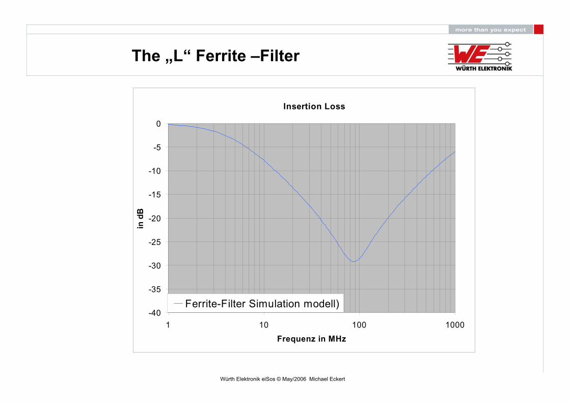
The „L“ Ferrite –Filter
Insertion Loss
-40
-35
-30
-25
-20
-15
-10
-5
0
1 10 100 1000
Frequenz in MHz
in d
B
Ferrite-Filter Simulation modell)
Würth Elektronik eiSos © May/2006 Michael Eckert
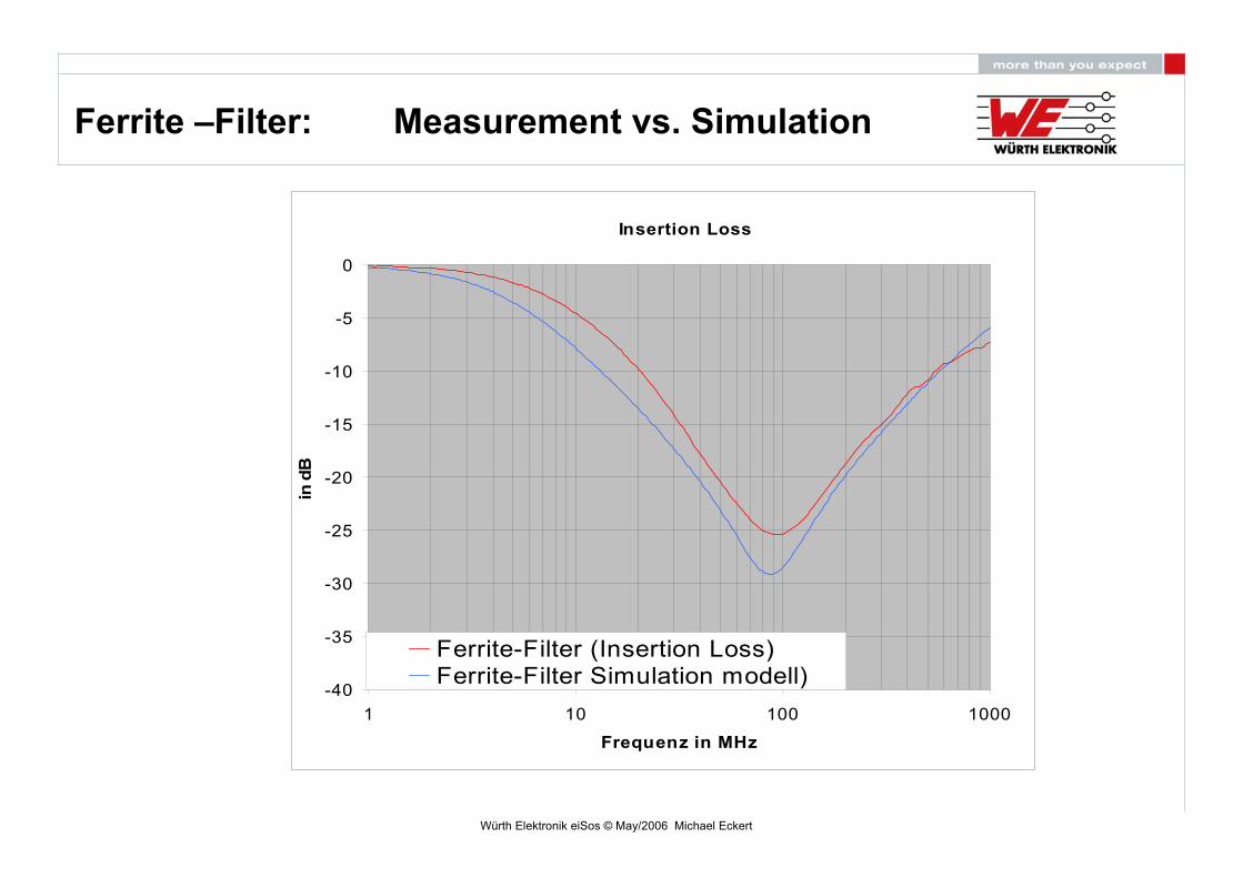
Ferrite –Filter: Measurement vs. Simulation
Insertion Loss
-40
-35
-30
-25
-20
-15
-10
-5
0
1 10 100 1000
Frequenz in MHz
in d
B
Ferrite-Filter (Insertion Loss)Ferrite-Filter Simulation modell)

Würth Elektronik eiSos © May/2006 Michael Eckert
LC-Filter
L=742 792 093
C=100nF

Würth Elektronik eiSos © May/2006 Michael Eckert
LC-Filter
Dämpfung
-100
-90
-80
-70
-60
-50
-40
-30
-20
-10
0
1 10 100 1000
Frequenz in MHz
in d
BLC-Filter (Simulationsmodell)

Würth Elektronik eiSos © May/2006 Michael Eckert
LC-Filter: Measurement vs. Simulation
Dämpfung
-100
-90
-80
-70
-60
-50
-40
-30
-20
-10
0
1 10 100 1000
Frequenz in MHz
in d
B
LC-Filter (Einfügedämpfung)LC-Filter (Simulationsmodell)
Würth Elektronik eiSos © May/2006 Michael Eckert
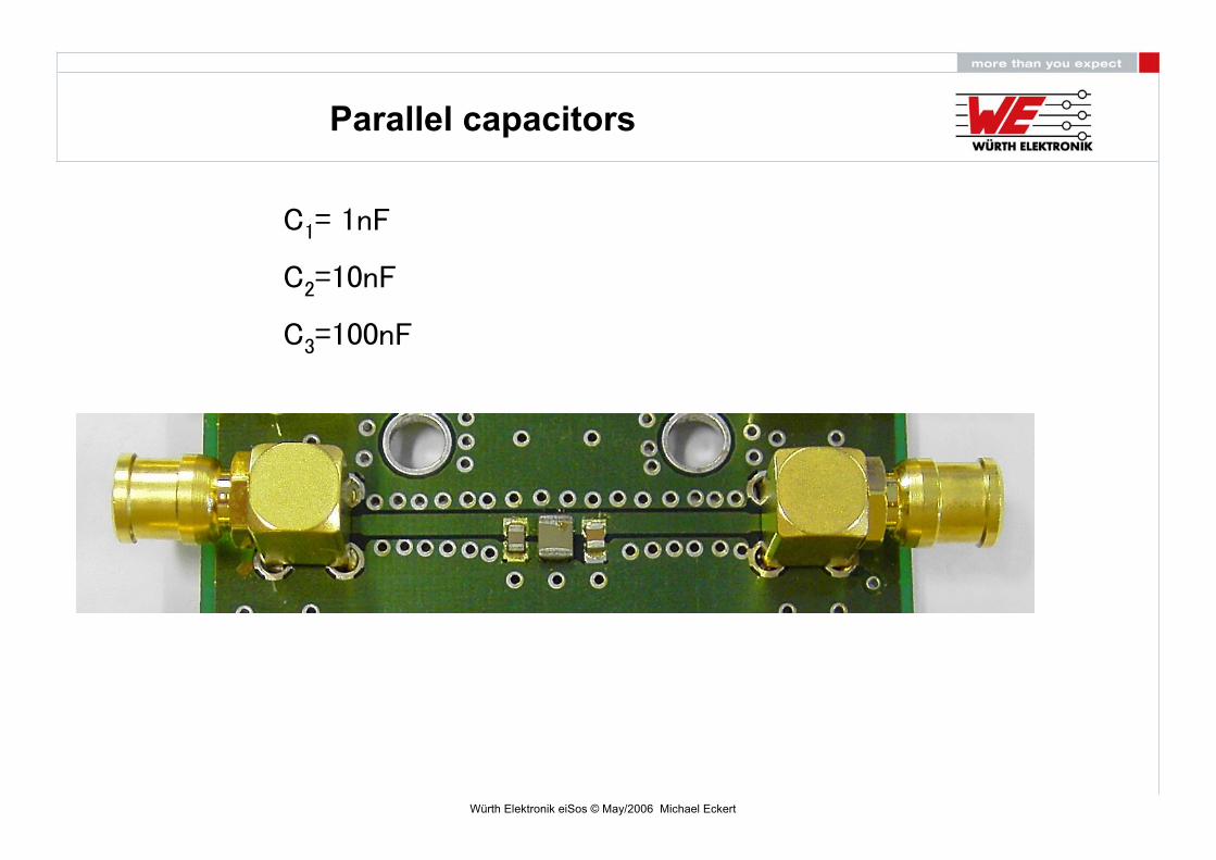
Parallel capacitors
C1= 1nF
C2=10nF
C3=100nF

Würth Elektronik eiSos © May/2006 Michael Eckert
Parallel capacitors
Dämpfung
-90
-80
-70
-60
-50
-40
-30
-20
-10
0
1 10 100 1000
Frequenz in MHz
in d
BC-Filter (Simulationsmodell)
Würth Elektronik eiSos © May/2006 Michael Eckert
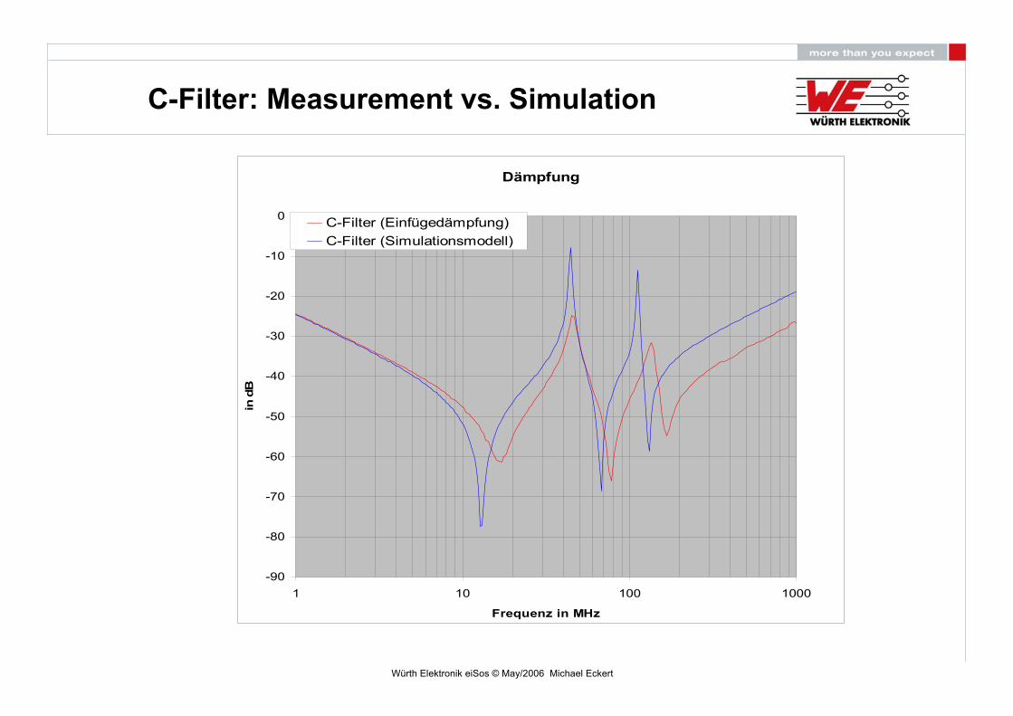
C-Filter: Measurement vs. Simulation
Dämpfung
-90
-80
-70
-60
-50
-40
-30
-20
-10
0
1 10 100 1000
Frequenz in MHz
in d
B
C-Filter (Einfügedämpfung)C-Filter (Simulationsmodell)
Würth Elektronik eiSos © May/2006 Michael Eckert
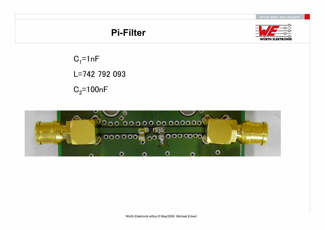
Pi-Filter
C1=1nF
L=742 792 093
C2=100nF

Würth Elektronik eiSos © May/2006 Michael Eckert
Pi-Filter
Dämpfung
-120
-100
-80
-60
-40
-20
0
1 10 100 1000
Frequenz in MHz
in d
BPi-Filter (Simulationsmodell)
Würth Elektronik eiSos © May/2006 Michael Eckert
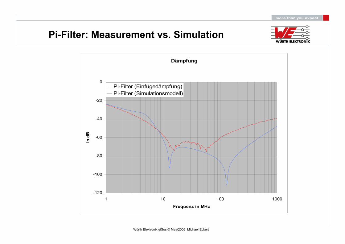
Pi-Filter: Measurement vs. Simulation
Dämpfung
-120
-100
-80
-60
-40
-20
0
1 10 100 1000
Frequenz in MHz
in d
BPi-Filter (Einfügedämpfung)Pi-Filter (Simulationsmodell)
Würth Elektronik eiSos © May/2006 Michael Eckert
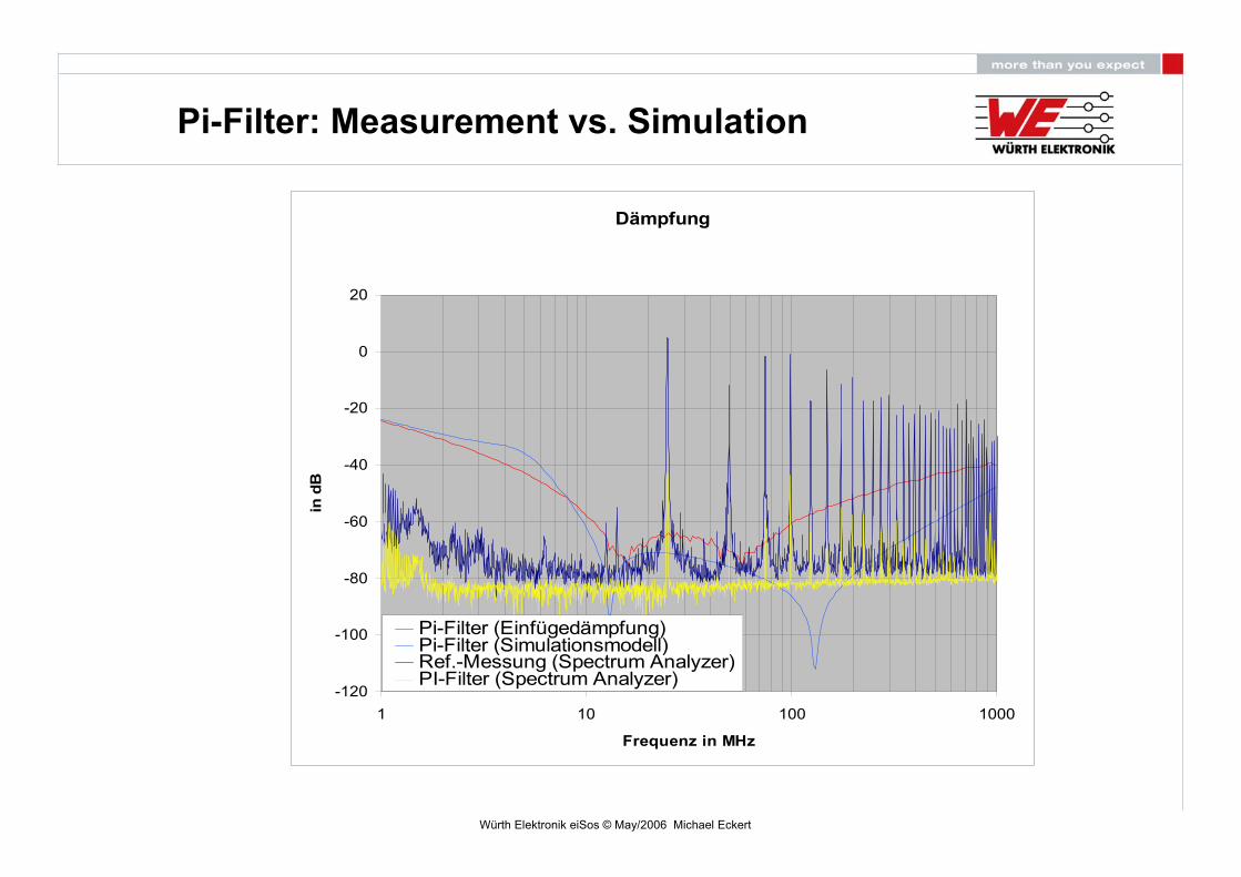
Pi-Filter: Measurement vs. Simulation
Dämpfung
-120
-100
-80
-60
-40
-20
0
20
1 10 100 1000
Frequenz in MHz
in d
B
Pi-Filter (Einfügedämpfung)Pi-Filter (Simulationsmodell)Ref.-Messung (Spectrum Analyzer)PI-Filter (Spectrum Analyzer)
Würth Elektronik eiSos © May/2006 Michael Eckert
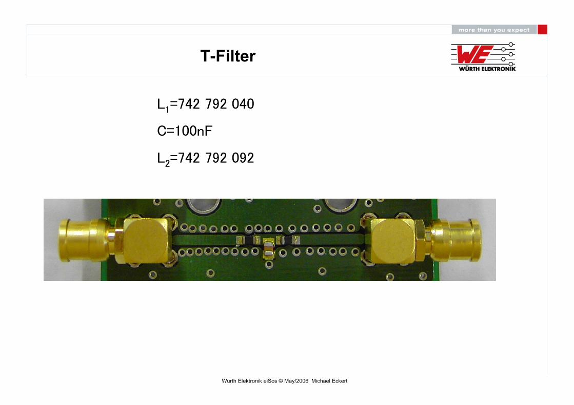
T-Filter
L1=742 792 040
C=100nF
L2=742 792 092

Würth Elektronik eiSos © May/2006 Michael Eckert
T-Filter
Dämpfung
-120
-100
-80
-60
-40
-20
0
1 10 100 1000
Frequenz in MHz
in d
BT-Filter (Simulationsmodell)

Würth Elektronik eiSos © May/2006 Michael Eckert
T-Filter: Measurement vs. Simulation
Dämpfung
-120
-100
-80
-60
-40
-20
0
1 10 100 1000
Frequenz in MHz
in d
B
T-Filter (Einfügedämpfung)T-Filter (Simulationsmodell)

Würth Elektronik eiSos © May/2006 Michael Eckert
Ferrite –Filter: Measurement vs. Simulation
Insertion Loss
-120
-100
-80
-60
-40
-20
0
20
1 10 100 1000
Frequenz in MHz
in d
B
Ferrite-Filter (Insertion Loss)Ferrits-Filter Simulation modell)Ref.-Meas. (Spectrum Analyzer)

Würth Elektronik eiSos © May/2006 Michael Eckert
Ferrite –Filter: Measurement vs. Simulation
Insertion Loss
-120
-100
-80
-60
-40
-20
0
20
1 10 100 1000
Frequenz in MHz
in d
B
Ferrite-Filter (Insertion Loss)Ferrite-Filter Simulation modell)Ref.-Meas. (Spectrum Analyzer)Ferrite-Filter (Spectrum Analyzer)

Würth Elektronik eiSos © May/2006 Michael Eckert
T-Filter: Measurement vs. Simulation
Dämpfung
-120
-100
-80
-60
-40
-20
0
20
1 10 100 1000
Frequenz in MHz
in d
B
T-Filter (Einfügedämpfung)T-Filter (Simulationsmodell)Ref.-Messung (Spectrum Analyzer)T-Filter (Spectrum Analyzer)
Würth Elektronik eiSos © May/2006 Michael Eckert
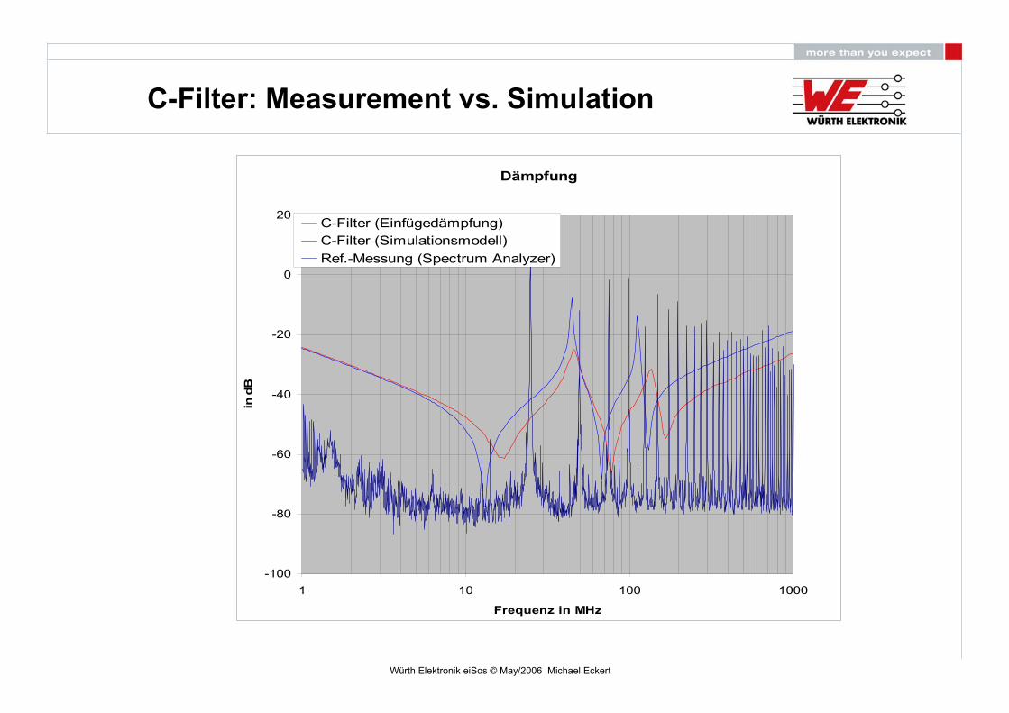
C-Filter: Measurement vs. Simulation
Dämpfung
-100
-80
-60
-40
-20
0
20
1 10 100 1000
Frequenz in MHz
in d
B
C-Filter (Einfügedämpfung)C-Filter (Simulationsmodell)Ref.-Messung (Spectrum Analyzer)

Würth Elektronik eiSos © May/2006 Michael Eckert
C-Filter: Measurement vs. Simulation
Dämpfung
-100
-80
-60
-40
-20
0
20
1 10 100 1000
Frequenz in MHz
in d
BC-Filter (Einfügedämpfung)C-Filter (Simulationsmodell)Ref.-Messung (Spectrum Analyzer)C-Filter (Spectrum Analyzer)
Würth Elektronik eiSos © May/2006 Michael Eckert
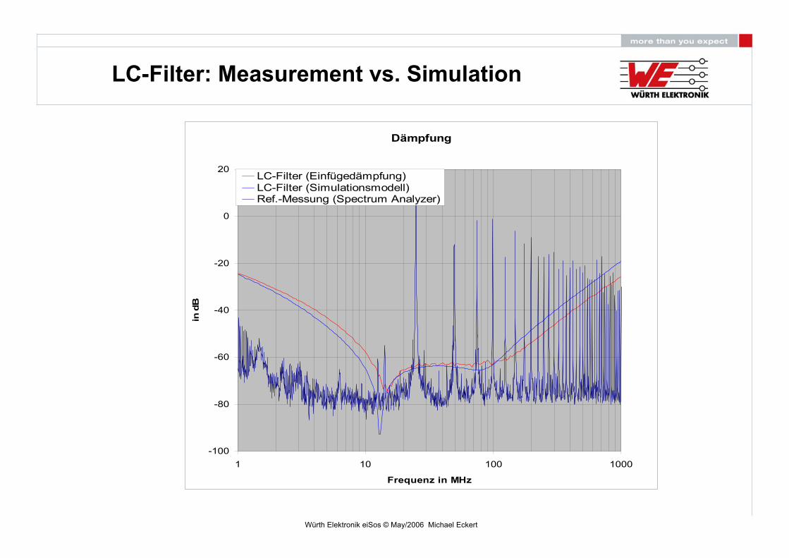
LC-Filter: Measurement vs. Simulation
Dämpfung
-100
-80
-60
-40
-20
0
20
1 10 100 1000
Frequenz in MHz
in d
B
LC-Filter (Einfügedämpfung)LC-Filter (Simulationsmodell)Ref.-Messung (Spectrum Analyzer)
Würth Elektronik eiSos © May/2006 Michael Eckert
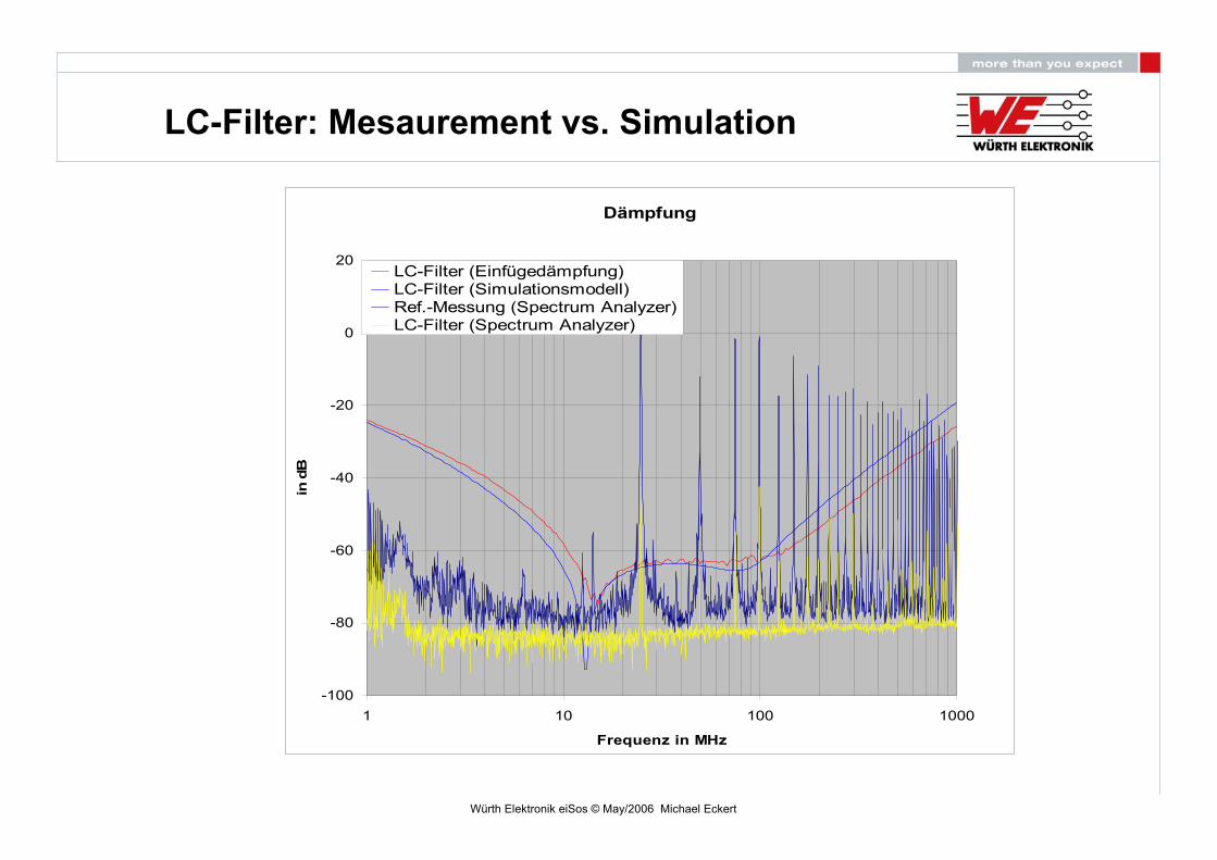
LC-Filter: Mesaurement vs. Simulation
Dämpfung
-100
-80
-60
-40
-20
0
20
1 10 100 1000
Frequenz in MHz
in d
B
LC-Filter (Einfügedämpfung)LC-Filter (Simulationsmodell)Ref.-Messung (Spectrum Analyzer)LC-Filter (Spectrum Analyzer)

Würth Elektronik eiSos © May/2006 Michael Eckert
Pi-Filter: Measurement vs. Simulation
Dämpfung
-120
-100
-80
-60
-40
-20
0
20
1 10 100 1000
Frequenz in MHz
in d
B
Pi-Filter (Einfügedämpfung)Pi-Filter (Simulationsmodell)Ref.-Messung (Spectrum Analyzer)

Würth Elektronik eiSos © May/2006 Michael Eckert
T-Filter: Measurement vs. Simulation
Dämpfung
-120
-100
-80
-60
-40
-20
0
20
1 10 100 1000
Frequenz in MHz
in d
BT-Filter (Einfügedämpfung)T-Filter (Simulationsmodell)Ref.-Messung (Spectrum Analyzer)
Würth Elektronik eiSos © May/2006 Michael Eckert
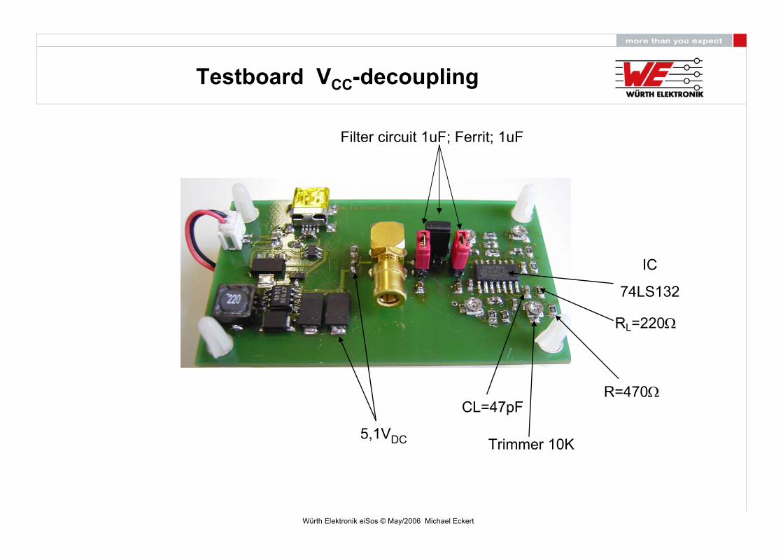
Testboard VCC-decoupling
5,1VDC Trimmer 10K
RL=220Ω
R=470Ω
IC
74LS132
CL=47pF
Filter circuit 1uF; Ferrit; 1uF
Würth Elektronik eiSos © May/2006 Michael Eckert
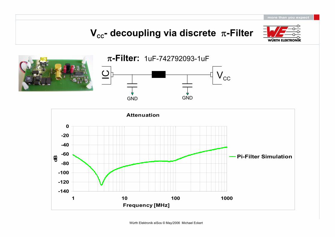
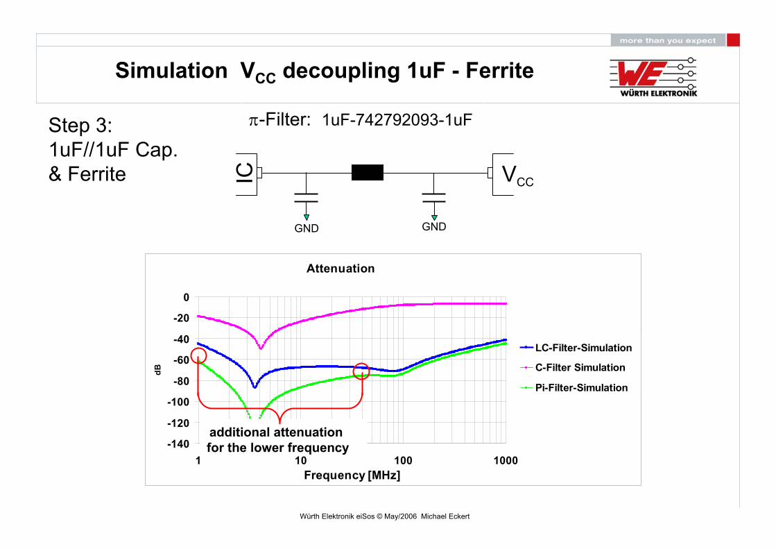
VCC- decoupling via discrete π-Filter
IC VCC
π-Filter: 1uF-742792093-1uF
GND GND
Attenuation
-140
-120
-100
-80
-60
-40
-20
0
1 10 100 1000Frequency [MHz]
dB
Pi-Filter Simulation
Würth Elektronik eiSos © May/2006 Michael Eckert
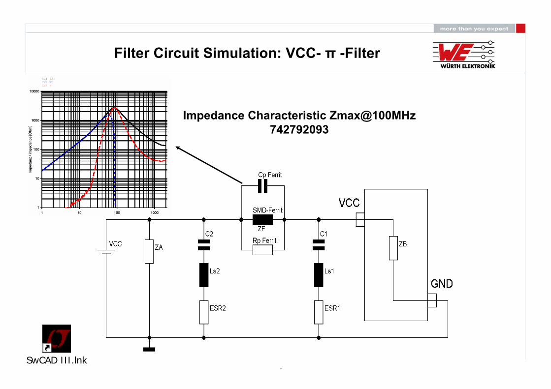
Filter Circuit Simulation: VCC- π -Filter
Impedance Characteristic Zmax@100MHz742792093
SwCAD III.lnk

Würth Elektronik eiSos © May/2006 Michael Eckert
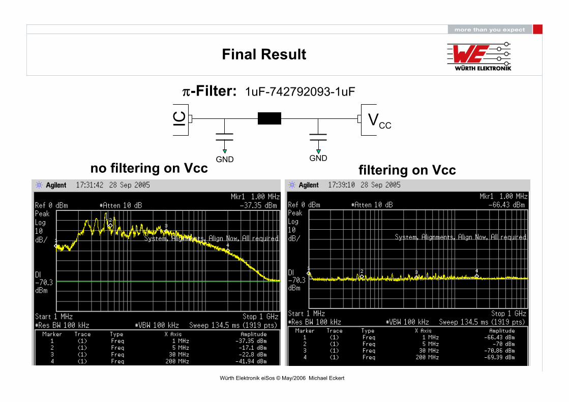
Noise-Spectrum on VCC
no filtering on Vcc(condition: max. Hold)

Würth Elektronik eiSos © May/2006 Michael Eckert
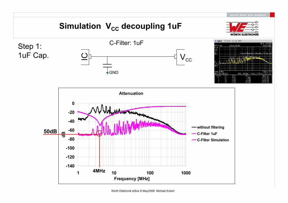
Simulation VCC decoupling 1uF
IC VCC
C-Filter with 1uF
GND
Attenuation
-140
-120
-100
-80
-60
-40
-20
0
1 10 100 1000Frequency [MHz]
dB
C-Filter
4MHz
50dB
Step 1:1uF Cap.
Würth Elektronik eiSos © May/2006 Michael Eckert
Attenuation
-140
-120
-100
-80
-60
-40
-20
0
1 10 100 1000Frequency [MHz]
dB
without filteringC-Filter 1uF C-Filter Simulation
IC VCC
C-Filter: 1uF
GND
Step 1:1uF Cap.
4MHz
50dB
Simulation VCC decoupling 1uF

Würth Elektronik eiSos © May/2006 Michael Eckert
Attenuation
-140
-120
-100
-80
-60
-40
-20
0
1 10 100 1000Frequency [MHz]
dB
LC-Filter-SimulationC-Filter Simulation
Step 2:1uF Cap.& Ferrite IC VCC
LC-Filter: 1uF-742792093
GND
Simulation VCC decoupling 1uF - Ferrite
main attenuationdone by the ferrite

Würth Elektronik eiSos © May/2006 Michael Eckert
Step 2:1uF Cap.& Ferrite IC VCC
LC-Filter: 1uF-742792093
GND
Attenuation
-140
-120
-100
-80
-60
-40
-20
0
1 10 100 1000Frequency [MHz]
dB
C-Filter 1uF
LC-Filter 1uF_742792093
without filtering
LC-Filter-Simulation
Simulation VCC decoupling 1uF - Ferrite
main attenuationdone by the ferrite
Würth Elektronik eiSos © May/2006 Michael Eckert
IC VCC
π-Filter: 1uF-742792093-1uF
GND GND
Attenuation
-140
-120
-100
-80
-60
-40
-20
0
1 10 100 1000Frequency [MHz]
dB
LC-Filter-Simulation
C-Filter Simulation
Pi-Filter-Simulation
Simulation VCC decoupling 1uF - Ferrite
Step 3:1uF//1uF Cap.& Ferrite
additional attenuationfor the lower frequency

Würth Elektronik eiSos © May/2006 Michael Eckert
IC VCC
π-Filter: 1uF-742792093-1uF
GND GND
Simulation VCC decoupling 1uF – Ferrite – 1uF
Attenuation
-140
-120
-100
-80
-60
-40
-20
0
1 10 100 1000Frequency [MHz]
dB
C-Filter-SimulationC-Filter 1uF LC-Filter 1uF_742792093 PI-Filter 1uF//1uF_742792093without filteringLC-Filter-SimulationPi-Filter-Simulation
Step 3:1uF//1uF Cap.& Ferrite
additional attenuationfor the lower frequency
Würth Elektronik eiSos © May/2006 Michael Eckert
no filtering on Vcc
Final Result
filtering on VccIC VCC
π-Filter: 1uF-742792093-1uF
GND GND
Würth Elektronik eiSos © May/2006 Michael Eckert
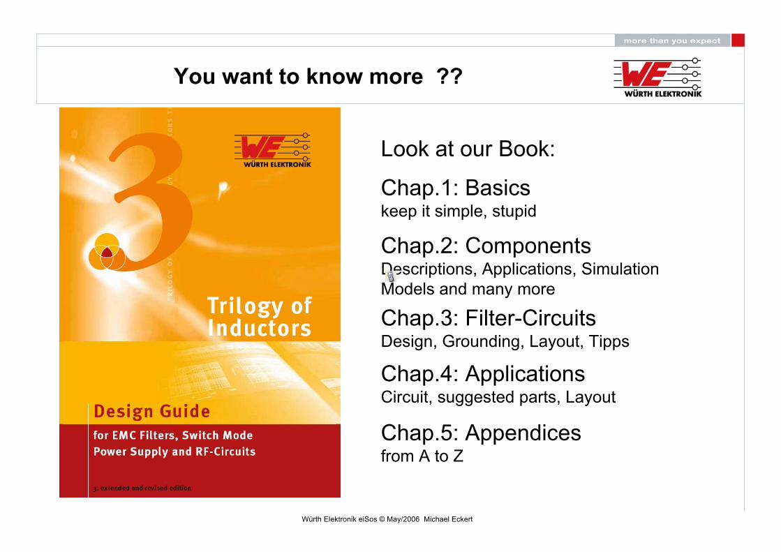
You want to know more ??
Look at our Book:
Chap.1: Basicskeep it simple, stupid
Chap.2: ComponentsDescriptions, Applications, Simulation Models and many more
Chap.3: Filter-CircuitsDesign, Grounding, Layout, Tipps
Chap.4: ApplicationsCircuit, suggested parts, Layout
Chap.5: Appendicesfrom A to Z
Würth Elektronik eiSos © May/2006 Michael Eckert
Online:
www.wewww.we--online.comonline.com