wvc-600 micro inverter wifi/433mhz user manual
TRANSCRIPT
WVC Series micro inverter
WVC-600 micro inverter
User manual
Intertek5016924
USC ETLINMETOR CE EMC
WiFi/433MHz Version

Micro inverterWVC600-433/WiFi
certificate CEC,CE,INMETOR,ETL,Patented technology
Loss of power at night
Total current harmonics
Appearance and technical features
Temperature range
Size(L×W×H)
Net amount
Waterproof grade
Heat dissipation mode
Communication mode
Power transmission mode
monitoring system
electromagnetic compatibility
Power grid
Power grid detection
<0.5W
<5%
-40°C to +65°C
283mm×200mm×41.6mm
1.56kg
Ip65 NEMA3R
Self-cooling
433MHz/WiFi
Reverse transmission,Load priority
Mobile phone APP、Browser
EN50081.part1 EN50082.Part1.CSA STD.C22.2 No.107.1
EN61000-3-2 EN62109.UL STD.1741
DIN VDE 0126 IEEE STD.1547.1547.1 and 1547.A
<0.5W
<5%
Maximum input power
Output voltage mode
PV Open circuit voltage
Operating voltage range
Starting voltage range
short-circuit current
Maximum working current
Output parameters
Output peak power
Rated output power
Output current
AC voltage range
AC frequency range
Power factor
Number of branch connections.
Output efficiency
Static MPPT efficiency
Max output efficiency
700Watt
120/230V Auto switch
30-60VOC
22-60V
22-60V
30A
24A
@120V
700Watt
600Watt
5A
80-160VAC
48-51Hz/58-61Hz
>95%
6PCS(Single)
@120V
99.5%
95%
@230V
700Watt
600Watt
2.6A
180-280VAC
>95%
12PCS(Single)
@230V
99.5%
95%
48-51Hz/58-61Hz
Size 342×240×115mm
Specifications
weight
Each(Packing)
2.8KG
Box(5PCS)
440×380×260mm
14KG
Packing weight
model WVC600-R3-433/WiFi
W
Parameter
Features
Maximum power point tracking
Reverse power transmission
I / O, fully isolated
Multiple parallel stacks
Adaptive voltage/frequency
Voltage mode microgrid
5G Iot Platform management
App monitoring system
Forward full-bridge topology
No installation, no maintenance
Internal high precision meter
System
WiFi Modem
433MHz WiFi
KDM Cloud server
APP Contorl
MeterSwitchPower Grid
Micro inverter
Computer
Photovoltaic module
WVC Series micro inverter
AC output terminal,
connect previous
/ next / connect to
grid access point
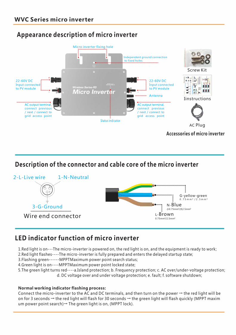
Independent ground connection
to fixed holes
12
3
Description of the connector and cable core of the micro inverter
L-Brown0.75mm²/2.5mm²
N-Blue小0.75mm²/大2.5mm²
G-yellow-green0 . 7 5 m m ² / 2 . 5 m m ²
2-L-Live wire 1-N-Neutral
3-G-Ground
Wire end connector
LED indicator function of micro inverter
1.Red light is on---The micro-inverter is powered on, the red light is on, and the equipment is ready to work;
2.Red light flashes----The micro-inverter is fully prepared and enters the delayed startup state;
3.Flashing green------MPPTMaximum power point search status;
4.Green light is on----MPPTMaximum power point locked state;
5.The green light turns red----a.Island protection; b. Frequency protection; c. AC over/under-voltage protection;
d. DC voltage over and under voltage protection; e. fault; f. software shutdown;
Normal working indicator flashing process:
Connect the micro-inverter to the AC and DC terminals, and then turn on the power → the red light will be
on for 3 seconds → the red light will flash for 30 seconds → the green light will flash quickly (MPPT maxim
um power point search)→ The green light is on, (MPPT lock).
Appearance description of micro inverter
Screw Kit
Iinstructions
AC Plug
Accessories of micro inverter
Micro inverter fixing hole
22-60V DC
Input connected
to PV module
Antenna
Status indicator
+
-
22-60V DC
Input connected
to PV module
AC output terminal,
connect previous
/ next / connect to
grid access point
WVC Series micro inverter
+
-
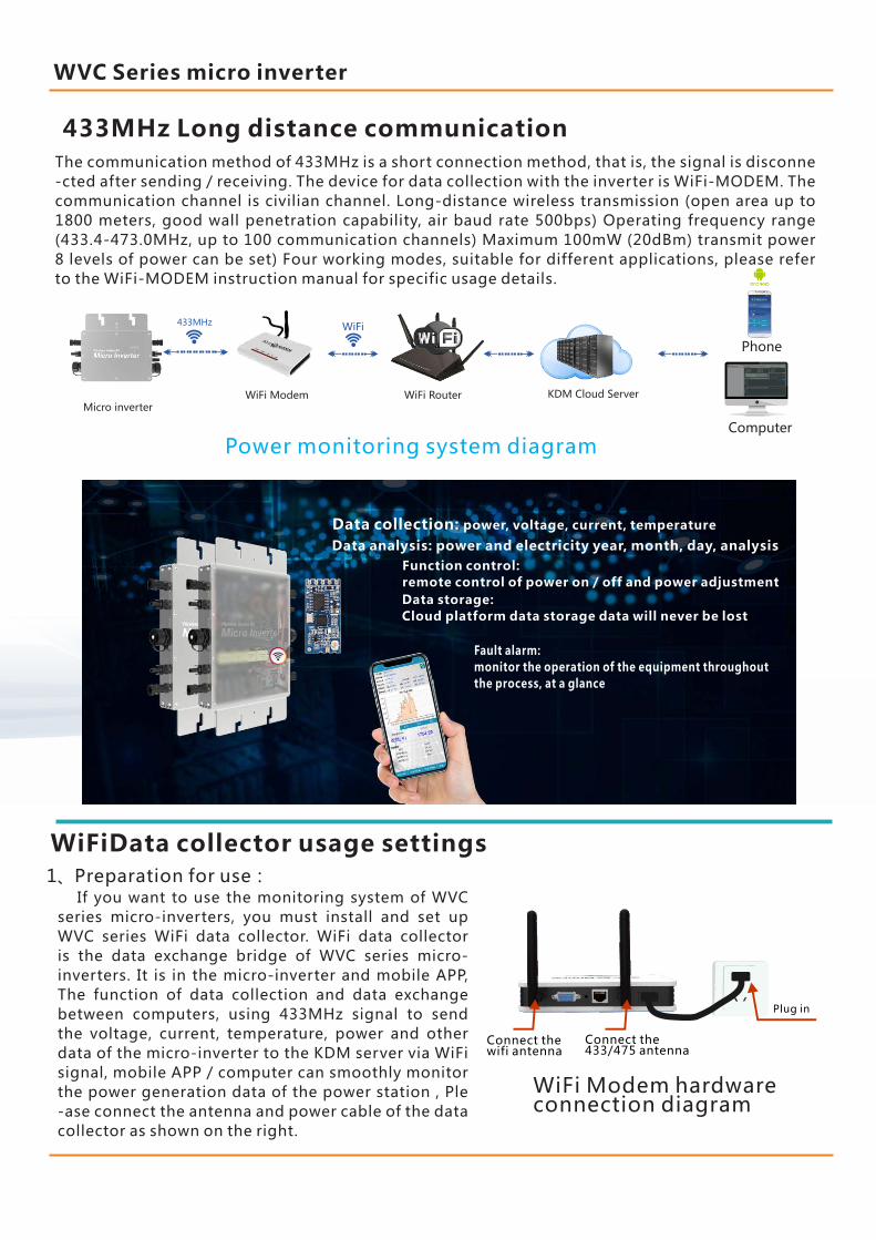
433MHz Long distance communication
The communication method of 433MHz is a short connection method, that is, the signal is disconne
-cted after sending / receiving. The device for data collection with the inverter is WiFi-MODEM. The
communication channel is civilian channel. Long-distance wireless transmission (open area up to
1800 meters, good wall penetration capability, air baud rate 500bps) Operating frequency range
(433.4-473.0MHz, up to 100 communication channels) Maximum 100mW (20dBm) transmit power
8 levels of power can be set) Four working modes, suitable for different applications, please refer
to the WiFi-MODEM instruction manual for specific usage details.
Computer
WiFi ModemMicro inverter
KDM Cloud Server
Phone
WiFi Router
Power monitoring system diagram
433MHz WiFi
WiFiData collector usage settings
1、Preparation for use:
Connect the 433/475 antenna
Plug in
Connect the wifi antenna
If you want to use the monitoring system of WVC
series micro-inverters, you must install and set up
WVC series WiFi data collector. WiFi data collector
is the data exchange bridge of WVC series micro-
inverters. It is in the micro-inverter and mobile APP,
The function of data collection and data exchange
between computers, using 433MHz signal to send
the voltage, current, temperature, power and other
data of the micro-inverter to the KDM server via WiFi
signal, mobile APP / computer can smoothly monitor
the power generation data of the power station , Ple
-ase connect the antenna and power cable of the data
collector as shown on the right.
WiFi Modem hardware connection diagram
433MHz远距离无线数据传输
Fault alarm:
monitor the operation of the equipment throughout
the process, at a glance
Data collection: power, voltage, current, temperature
Data analysis: power and electricity year, month, day, analysis
Function control:
remote control of power on / off and power adjustment
Data storage:
Cloud platform data storage data will never be lost
WVC Series micro inverter

2、APP Phone Settings:A) Please visit our company's official website to download the
kaideng-app.apk app and install it on your Android phone, then
click the Kaideng app to enter the login interface, then click the
collector to initialize.As shown in Figure 1:
Figure 1 Figure 2
B) As shown in Figure 2, click the red circle to select HF-A11x_AP in
the AP SSID of the collector, click thecompany WiFi SSID to select the
WiFi network name in your home, and enter the password in the WiFi
password.
The WiFi name of theSelected moduleSelect the WiFi hotsp-ot in use
Enter WiFi password
C) After all are entered, first select the drop-down menu of the
mobile phone and long press the network to select the HF-A11x_AP
connection, as shown in Figure 3, and close the data connection of
the mobile phone, as shown in Figure 4:
Figure3 Figure4
Note: Because HF-A11x_AP is not connected to the Internet, the
Android phone will automatically disconnect the network, which
will make our initialization unsuccessful. Please find the automatic
switching functionin the Android phone's system settings and turn
it off.
D) After all are entered, first select the drop-down menu of the
mobilephone and long press the network to select the HF-A11x_AP
connection, as shown in Figure 3, and close the data connection of
the mobile phone, as shown in Figure 4:
Figure5 Figure6
E) Most smartphones automatically select a network. When the
connected network pops up and there is no Internet access signal,
be sure to choose to keep connected to ensure that the initialization
is carried out smoothly, as shown in Figure 5, and the initialization is
completed at the last point, as shown in Figure 6 As shown.
Figure7
3、Computer Settings:
A) Click on the computer to connect to the WiFi network of HF-A11x_AP
as shown in Figure 8, open the browser in the computer, enter the IP
address: 10.10.100.254, enter in the name: admin, enter in the password
field: admin.
Figure8
Figure9
1、Select STA mode on Mode Selection, as shown in Figure 10:
2、Click Search on the STA Interface Setting to search the network as shown
in Figure 11:
3、Select your own network in the searched network list as shown in
Figure 12:
4、Click Search on the STA Interface Setting to search the network,
and enter the password in the Pass Phrase and click Apply, as shown
in Figure 13:
Figure12
Figure13
Figure10 Figure11
5、In Application Setting, select Mode as Client> enter Port 1234>
enter Server Address 47.115.28.119> click Apply to confirm as shown
in Figure 14:
Figure14
6、Restart the device in Device Management to complete the settings
as shown in Figure 15:
Figure15
As Shown in Figure 9:
WVC Series micro inverter
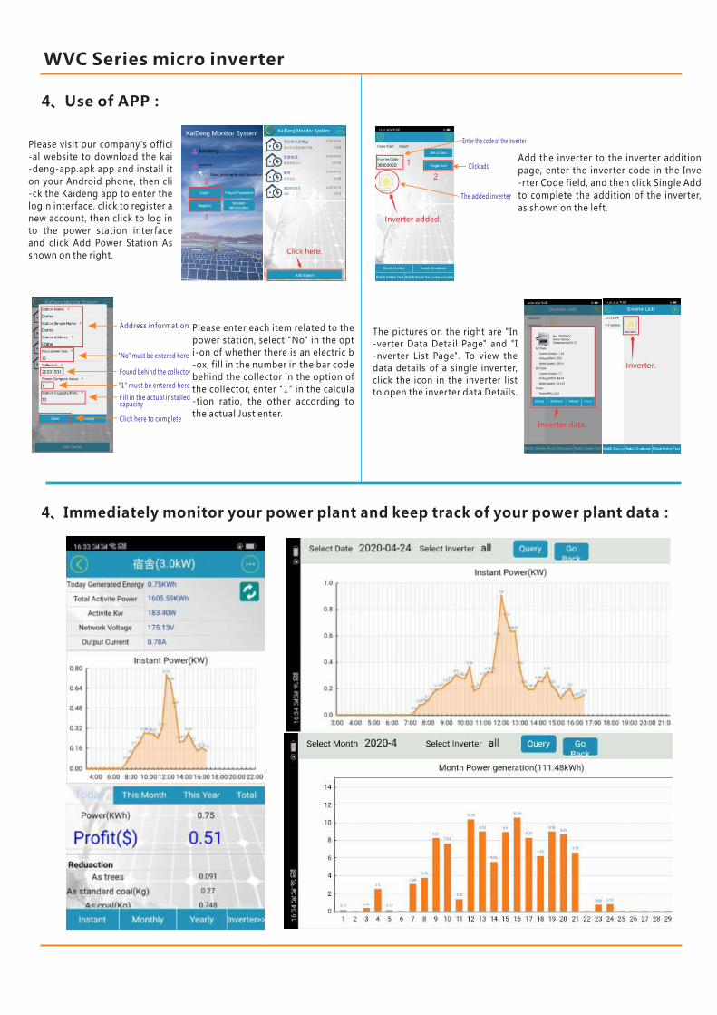
4、Use of APP:
Please visit our company's offici
-al website to download the kai
-deng-app.apk app and install it
on your Android phone, then cli
-ck the Kaideng app to enter the
login interface, click to register a
new account, then click to log in
to the power station interface
and click Add Power Station As
shown on the right.
Please enter each item related to the
power station, select "No" in the opt
i-on of whether there is an electric b
-ox, fill in the number in the bar code
behind the collector in the option of
the collector, enter "1" in the calcula
-tion ratio, the other according to
the actual Just enter.
Address information
"No" must be entered here
Found behind the collector
"1" must be entered here
Fill in the actual installed capacity
Click here to complete
Add the inverter to the inverter addition
page, enter the inverter code in the Inve
-rter Code field, and then click Single Add
to complete the addition of the inverter,
as shown on the left.
Enter the code of the inverter
Click add
The added inverter
The pictures on the right are "In
-verter Data Detail Page" and "I
-nverter List Page". To view the
data details of a single inverter,
click the icon in the inverter list
to open the inverter data Details.
4、Immediately monitor your power plant and keep track of your power plant data:
WVC Series micro inverter
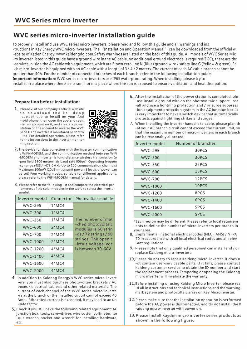
WVC series micro-inverter installation guide
Preparation before installation:
Please visit our company's official website
t o d o w n l o a d t h e k a i - d e n g
-app.apk app to install on your And
-roid phone, then open the app and regis
-ter an account on it, and create a power
station on the account to reverse the WVC
series. The inverter is monitored or contro
-lled. For detailed operation, please refer
to the instructions in the inverter monitor
-ing section.
1、
The device for data collection with the inverter communication
is WiFi-MODEM, and the communication method between WiFi
-MODEM and inverter is long-distance wireless transmission (o
-pen field 1800 meters, air baud rate 00bps). Operating frequen
-cy range (433.4-473.0MHz Up to 100 communication channels)
Maximum 100mW (20dBm) transmit power (8 levels of power can
be set) Four working modes, suitable for different applications,
please refer to the WiFi-MODEM manual for details.
2、
Please refer to the following list and compare the electrical par
-ameters of the solar modules in the table to select the inverter
model.
3、
Inverter model Connector Photovoltaic module
WVC-295
WVC-300
WVC-350
WVC-600
WVC-700
WVC-1000
WVC-1200
WVC-1400
WVC-1600
WVC-2000
1*MC4
1*MC4
1*MC4
2*MC4
2*MC4
2*MC4
4*MC4
4*MC4
4*MC4
4*MC4
The number of mat
-ched photovoltaic
modules is 60 strin
-gs / 72 strings / 90
strings. The open c
-ircuit voltage Voc
is between 30-60V
In addition to Kaideng Energy's WVC series micro-invert
-ers, you must also purchase photovoltaic brackets / AC
boxes / electrical cables and other related materials. The
current of each channel of the WVC series micro-inverte
-rs at the branch of the installed circuit cannot exceed 40
Amp, if the rated current is exceeded, it may lead to an un
-safe factor.
4、
To properly install and use WVC series micro inverters, please read and follow this guide and all warnings and ins
-tructions in Kay Energy WVC micro inverters. The “Installation and Operation Manual” can be downloaded from the official w
-ebsite of Kaden Energy: www.kaidengdg.com.Safety warnings are listed on the back of this guide. All models of WVC Series Mic
-ro inverter listed in this guide have a ground wire in the AC cable, no additional ground electrode is required(EGC), there are thr
-ee wires in-side the AC cable with equipment, which are Blown zero line N (Blue) ground wire / safety line G (Yellow & green). Ea
-ch micro-inverter is equipped with an AC cable with a length of 3 * 4 * 2 meters. The current of each AC cable branch cannot be
greater than 40A. For the number of connected branches of each branch, refer to the following installat-ion guide.
Important information: WVC series micro-inverters use IP65 waterproof rating. When installing, please try to
install it in a place where there is no rain, nor in a place where the sun is exposed to ensure ventilation and heat dissipation.
Check if you still have the following related equipment: AC
junction box, tools: screwdriver, wire cutter, voltmeter, tor
-que wrench, socket and wrench for installing hardware,
etc.
5、
After the installation of the power station is completed, ple
-ase install a ground wire on the photovoltaic support, inst
-all and use a lightning protection and / or surge suppress
-ion equipment protection system in the AC junction box. It
is very important to have a switch device that automatically
protects against lightning strikes and surges.
6、
When installing the inverter handshake cable, please plan th
-at your AC branch circuit cannot exceed the current limit, so
that the maximum number of micro-inverters in each branch
can be reasonably allocated.
7、
Inverter model Number of branches
30PCS
30PCS
25PCS
15PCS
12PCS
10PCS
8PCS
6PCS
5PCS
5PCS
WVC-295
WVC-300
WVC-350
WVC-600
WVC-700
WVC-1000
WVC-1200
WVC-1400
WVC-1600
WVC-2000
8、
*Each region may be different. Please refer to local requirem
-ents to define the number of micro-inverters per branch in
your area.Implement all national electrical codes (NEC), ANSI / NFPA
70 in accordance with all local electrical codes and all relev
-ant regulations.
Please note that only qualified personnel can install and / or
replace Kaideng micro-inverters.
9、
Please do not try to repair Kaideng micro-inverter. It does n
-ot contain user-serviceable parts. If it fails, please contact
Kaideng customer service to obtain the ID number and start
the replacement process. Tampering or opening the Kaideng
micro inverter will invalidate the warranty.
10、
Before installing or using Kaideng Micro Inverter, please rea
-d all instructions and technical instructions and the warning
mark system and photovoltaic array on Kay Microinverter.
11、
Please make sure that the installation operation is performed
before the AC power is disconnected, and do not install the K
-aideng micro-inverter with power on.
12、
13、Please install Kayden micro inverter series products as
shown in the following figure.
WVC Series micro inverter
System support:
APP Contorl
Wiring Diagram WVC-600 Triple Phase
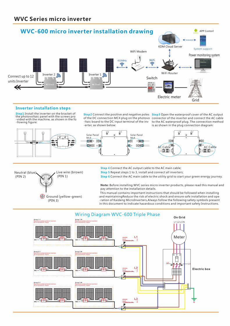
WVC-600 micro inverter installation drawing
Step1 Install the inverter on the bracket of the photovoltaic panel with the screws pro-vided with the machine, as shown in the fo-llowing figure:
Step2 Connect the positive and negative poles
of the DC connection MC4 plug on the photovo
-ltaic board to the DC input terminal of the inv
-erter, as shown below:
Step3 Open the waterproof cover of the AC output
connector of the inverter and connect the AC cable
to the AC waterproof plug. The connection method
is as shown in the plug connection diagram:
Inverter installation steps
Connect up to 12
units Inverter
Grid
Power monitoring system
Electric meter
Switch
WiFi Modem
433MHz WiFi
KDM Cloud Server
WiFi Router
AC Cable AC Cable
Step 4 Connect the AC output cable to the AC main cable;
Step 5 Repeat steps 1 to 3, install and connect all inverters;
Step 6 Connect the AC main cable to the utility grid to start your green energy journey.
Note: Before installing WVC series micro inverter products, please read this manual and
pay attention to the installation details.
This manual contains important instructions that should be followed when installing
and maintainingReduce the risk of electric shock and ensure safe installation and ope
-ration of Kaideng MicroInverters,Always follow the following safety symbols present
in this document to indicate hazardous conditions and important safety Instructions.
Inverter 1Inverter 2
Solar Panel
Mc4
Solar Panel
Mc4
Neutral (blue)
(PIN 2)
Live wire (brown)
(PIN 1)
Ground (yellow-green)
(PIN 3)
3 1
2
WVC Series micro inverter
G
L1L3
MeterBROWN - L1BLUE - NGREEN&YELLOW - G
BROWN - L2BLUE - NGREEN&YELLOW - G
BROWN - L3BLUE - NGREEN&YELLOW - G
On Grid
L1 L2 L3 N
Array 1-1Maximum number of micro invertersper array branch: 12 pcs
Maximum number of micro invertersper array branch: 12 pcs
Array 1-N
Array 2-1Maximum number of micro invertersper array branch: 12 pcs
Maximum number of micro invertersper array branch: 12 pcs
Array 2-N
Array 3-1Maximum number of micro invertersper array branch: 12 pcs
Maximum number of micro invertersper array branch: 12 pcs
Array 3-N
Electric box