wwaatteerr--ccoooolleedd aauuttoommaattiicc mmiigg ... - 450a-600a... · wwaatteerr--ccoooolleedd...
TRANSCRIPT
1
WWaatteerr--CCoooolleedd AAuuttoommaattiicc MMIIGG
TToorrcchheess For Models
450A,550A,600A
INSTALLATION, OPERATIONS AND REPLACEMENT PARTS MANUAL
2
TABLE OF CONTENTS
INTRODUCTION/WARRANTY ....................................................................................................................................... 2
GENERAL SAFETY ...................................................................................................................................................... 4
TORCH SPECIFICATIONS ............................................................................................................................................. 4
NOZZLE/TIP RELATIONSHIPS ....................................................................................................................................... 5
INSTALLATION .......................................................................................................................................................... 5
LINER REPLACEMENT ................................................................................................................................................ 6
GOOSENECK REPLACEMENT ........................................................................................................................................ 7
UNICABLE REPLACEMENT ........................................................................................................................................... 7
DAILY MAINTENANCE ............................................................................................................................................... 8
NOZZLE SELECTION CHART ......................................................................................................................................................... 9
CONTACT TIP SELLECTION CHART .............................................................................................................................. 10
PARTS BREAKDOWN .......................................................................................................................................... 11-14
INTRODUCTION
Thank you for purchasing an American Weldquip product. The American Weldquip product you have purchased has been carefully manufactured, assembled, and fully tested. This manual contains information on the installation, operation, maintenance, and replacement part breakdown. Please read, understand, and follow all safety instructions, warnings and procedures. Keep this manual handy for referencing installation, operation, maintenance, and part ordering information. While every precaution has been taken as to the accuracy in this manual, American Weldquip, Inc. assumes no responsibility for errors or omissions. American Weldquip, Inc. assumes no liability for damages resulting from the use of the information contained in this manual. American Weldquip, Inc. shall have no liability to the buyer for consequential damages or expenses by any defect whatsoever.
WARRANTY
AMERICAN WELDQUIP MIG guns and parts are warranted to be free of defects in material and/or workmanship for the period
of time listed below. For any product found to be defective under normal use, AMERICAN WELDQUIP, INC. at our option, will
repair, replace or issue a credit for the value of the defective product. All warranty claims must be submitted by the original
purchaser. Use of non-genuine AMERICAN WELDQUIP parts and/or consumables may damage and/or severely limit the
performance of the equipment which may limit or void any warranties. AMERICAN WELDQUIP, INC. will not assume
responsibility for incidental damages or expenses related to any defect. This warranty does not cover damage caused by misuse
or abuse, accident, alteration of product, improper installation, misapplication, lack of reasonable care and maintenance,
unauthorized repairs or modifications, loss of use while at a repair facility or other conditions that are beyond the control of
American Weldquip, Inc.
A Return Authorization Number (RA#) must be attained from the factory for any product being returned for Warranty Repair or
Replacement. All returned product must be shipped freight prepaid by the sender. No- charge replacements, repaired
products, or credit will be issued, once the returned product has been evaluated and warranty condition has been verified. If an
immediate replacement is required before proper warranty evaluation, a purchase order number is required and the goods will
be invoiced. A credit will be issued once it is determined that a warranty condition exists.
STANDARD WARRANTY
All Semi-Automatic, Automatic, Robotic MIG TORCHES and Components = 120 Days
MIG Torch Trigger Switches (Contacts only) -Excludes Smoke Extraction = LIFETIME
Robotic Nozzle Cleaning Stations, Wire Cutter = 90 Days
Robotic Peripherals, ArcSafe, Gun Mounts = 90 Days
TIG POINT Tungsten Electrode Grinders = 90 Days
3
LIMITED EXTENDED WARRANTY PROTECTION
This limited extended warranty protection expands coverage to loyal customers who use all GENUINE American Weldquip
consumables. Customers filing a claim under the extended warranty will need to prove, by providing past invoices, that they
have been purchasing and using Genuine American Weldquip consumables.
All Semi-Automatic, Automatic, Robotic MIG TORCHES and Components = 1 YEAR
MIG Torch Trigger Switches (Contacts only) -Excludes Smoke Extraction = LIFETIME
MIG Torch Handles = LIFETIME
Robotic Nozzle Cleaning Stations, Wire Cutter = 90 Days
Robotic Peripherals, ArcSafe, Gun Mounts = 90 Days
TIG POINT Tungsten Electrode Grinders = 90 Days
ROHS COMPLIANT
RoHS (Restriction of Hazardous Substances) is an environmental law which addresses the European Union directive 2002/95/EC known as the RoHS Directive. The RoHS directive restricts the use of hazardous substances listed below in electrical and electronic equipment. While it is not a requirement to meet the directive in the United States, at this time, American Weldquip Inc. feels this is an important part of our “Go Green initiative. We have taken all reasonable steps to try to insure the supporting evidence regarding the absence of the restricted substances to support RoHS compliance. For reference, the maximum concentration values of the restricted substances by weight in homogenous materials are: Lead/Lead Components - 0.1% Mercury - 0.1% Hexavalent Chromium - 0.1% Polybrominated Biphenyls (PBBs) - 0.1% Polybrominated Diphenyl Ethers (PBDEs) - 0.1% Cadmium -0.01% For RoHS Certification of Compliance Letter on a particular product please visit our website – www.weldquip.com or email us at [email protected] or call 330-239-0317.
4
GENERAL SAFETY PRECAUTIONS
Before installing, operating or performing maintenance please read the safety precautions below. Failure to observe safety precautions can result in injury or death.
WARNING – A welding arc emits ultraviolet (UV) and other radiation and can cause serious injury to unprotected skin and eyes.
WARNING – Hot metal produced by welding can cause severe burns. Heat from arcs and hot weld spatter and sparks can start fires and cause explosions of flammable gases.
WARNING – Fumes and gases generated from welding can cause severe injury to respiratory system and even death. DO NOT weld in confined spaces and make sure there is plenty of ventilation. Do not breathe fumes and gases as can cause asphyxiation.
WARNING – Electrical shock can kill. Do not touch live electrical parts and/or use in damp locations.
1. Always wear a welding helmet with the correct filter and cover plate. 2. Always wear safety Glasses with side shields in any work area even if a welding helmet is also required. 3. All exposed skin should be covered with flameproof protective clothing. This includes leather gloves, heavy long
sleeve shirt, cuff less pants and high topped shoes. DO NOT WEAR CLOTHING MADE FROM FLAMMABLE SYNTHETIC FIBERS.
4. Protective screens or barriers should be used to protect others from spatter, flash and glare while welding. 5. Make sure work area is free of all combustible materials or cover with a protective non-flammable cover. 6. Remove all flammable gas cylinders as welding sparks can cause explosion in the event of a leak. Take serious
precautions if welding in area of flammable gas lines and/or tanks. 7. Know where a fire extinguisher is at all times. The best practice is to have an extinguisher, water pail, fire hose and/or
sand bucket available for immediate use. 8. Poorly maintained equipment can cause injury or death 9. Inspect, repair or replace worn or damaged welding cables and torch leads. 10. Insure equipment is properly grounded and installed according to code. 11. Never wrap the weld cable or torch leads around your body. 12. Make sure equipment is turned off when not in use.
ADDITIONAL SOURCES FOR SAFETY INFORMATION ANSI Standard Z49.1 CODE FOR SAFETY IN WELDING AND CUTTING - American National Standards Institute, 1430 Broadway, New York, NY 10018 NFPA Standard 51B, “Fire Prevention in the Use of Cutting and Welding Processes – National Fire Protection Association, Batterymarch Park, Quincy, MA 02269 CSA Standard W117.2 CODE FOR SAFETY IN WELDING AND CUTTING - Canadian Standards Association, Standards Sales, 178 Rexdale Boulevard, Rexdale, Ontario, Canada M9W 1R3.
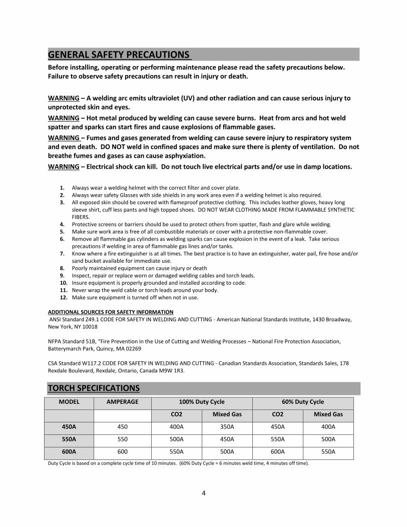
TORCH SPECIFICATIONS
MODEL AMPERAGE 100% Duty Cycle 60% Duty Cycle
CO2 Mixed Gas CO2 Mixed Gas
450A 450 400A 350A 450A 400A
550A 550 500A 450A 550A 500A
600A 600 550A 500A 600A 550A
Duty Cycle is based on a complete cycle time of 10 minutes. (60% Duty Cycle = 6 minutes weld time, 4 minutes off time).
5
NOZZLE/TIP RELATIONSHIPS
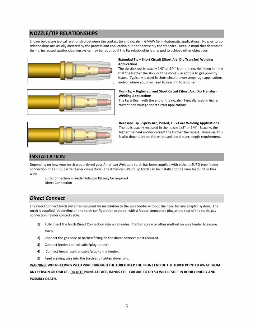
Shown below are typical relationship between the contact tip and nozzle in GMAW Semi-Automatic applications. Nozzles to tip relationships are usually dictated by the process and application but not necessarily the standard. Keep in mind that decreased tip life, increased spatter cleaning cycles may be required if the tip relationship is changed to achieve other objectives.
Extended Tip – Short Circuit (Short Arc, Dip Transfer) Welding Applications The tip stick out is usually 1/8” or 1/4” from the nozzle. Keep in mind that the further the stick out the more susceptible to gas porosity issues. Typically is used in short circuit, lower amperage applications, and/or where you may need to reach in to a corner.
Flush Tip – Higher current Short Circuit (Short Arc, Dip Transfer) Welding Applications The tip is flush with the end of the nozzle. Typically used in higher current and voltage short circuit applications.
Recessed Tip – Spray Arc, Pulsed, Flux Core Welding Applications The tip is usually recessed in the nozzle 1/8” or 1/4”. Usually, the higher the heat and/or current the further the recess. However, this is also dependant on the wire used and the arc length requirement.
INSTALLATION
Depending on how your torch was ordered your American Weldquip torch has been supplied with either a EURO type feeder connection or a DIRECT wire feeder connection. The American Weldquip torch can be installed to the wire feed unit in two ways.
Euro Connection – Feeder Adaptor Kit may be required Direct Connection
Direct Connect
The direct connect torch system is designed for installation to the wire feeder without the need for any adaptor system. The torch is supplied (depending on the torch configuration ordered) with a feeder connection plug at the rear of the torch, gas connection, feeder control cable.
1) Fully insert the torch Direct Connection into wire feeder. Tighten screw or other method on wire feeder to secure
torch
2) Connect the gas hose to barbed fitting on the direct connect pin if required.
3) Connect feeder control cable/plug to torch.
4) Connect feeder control cable/plug to the feeder.
5) Feed welding wire into the torch and tighten drive rolls.
WARNING: WHEN FEEDING WELD WIRE THROUGH THE TORCH KEEP THE FRONT END OF THE TORCH POINTED AWAY FROM
ANY PERSON OR OBJECT. DO NOT POINT AT FACE, HANDS ETC. FAILURE TO DO SO WILL RESULT IN BODILY INJURY AND
POSSIBLY DEATH.
6
Using Feeder Adaptor Kit
In some cases it may be desirable to use a feeder adaptor kit such as when using different manufactures wire feed units to commonize on a torch configuration.
1) Thread feeder adaptor plug into the adaptor block and tighten.
2) Insert the adaptor guide tube into the adaptor plug.
3) Fully insert the feeder adaptor assembly into the wire feeder. Tighten screw or other method on wire feeder to
secure the adaptor assembly.
4) If required, connect the feeder control cable/plug to the wiring on the adaptor assembly.
5) Connect feeder control cable/plug to the feeder.
6) Connect the torch to the feeder adaptor assembly.
7) Feed welding wire into the torch and tighten drive rolls.
WARNING: WHEN FEEDING WELD WIRE THROUGH THE TORCH KEEP THE FRONT END OF THE TORCH POINTED AWAY FROM
ANY PERSON OR OBJECT. DO NOT POINT AT FACE, HANDS ETC. FAILURE TO DO SO WILL RESULT IN BODILY INJURY AND
POSSIBLY DEATH.
Torch Mount Installation
The robotic torch has a precious locating flat for accurate locating in the mating torch mount.
1) Loosen the cap screw in the torch mount.
2) Insert the torch through the top of the mount lining the locating flat on the torch with the mating flat on the torch
mount.
3) Fully insert the torch into the torch mount.
4) Tighten the cap screw to secure the torch into the torch mounting arm.
MAINTENANCE
Liner Replacement
There are two types of liners offered – standard and the EASY front loading liner system. The standard liner requires the torch be removed from the feeder in order to be changed. The EASY front load system only requires the removal of the front end consumables.
Standard Liner Maintenance
Warnings – To avoid accidental injury ensure power supply and wire feed unit is turned off.
1) Trim the end of the weld wire at contact tip. 2) Retract or completely remove weld wire so torch can be removed from the wire feeder. 3) Remove the nozzle, contact tip and diffuser. 4) Loosen the set screw at the torch feeder connection using a 5/64” Allen wrench. 5) Making sure the torch cable is straight, grasp the liner at the rear of the torch with a pair of pliers and remove. 6) Carefully feed the new liner into the torch using short strokes to avoid kinking. You may need to twist the liner for
easier insertion. 7) Tighten the set screw to secure the liner in the torch. 8) Reinstall the torch to the wire feed unit. 9) IMPORTANT: at the front end of the torch push the liner back into the gun and hold in place.

7
10) Trim the liner to ¾” stick out from the end of the gooseneck. 11) Replace the Diffuser, contact tip and nozzle. 12) Feed welding wire into the torch and tighten drive rolls.
WARNING: WHEN FEEDING WELD WIRE THROUGH THE TORCH KEEP THE FRONT END OF THE TORCH POINTED AWAY FROM
ANY PERSON OR OBJECT. DO NOT POINT AT FACE, HANDS ETC. FAILURE TO DO SO WILL RESULT IN BODILY INJURY AND
POSSIBLY DEATH.
Gooseneck Replacement
1) Secure Gooseneck in a vice. 2) Remove the liner from the torch. 3) Remove the four handle screws and separate the handle assembly. 4) Using a wrench loosen the gooseneck / cable connection and remove from the cable assembly. 5) Remove the Body Insulator from the old gooseneck and install on the new one. 6) Thread the new gooseneck on to the cable assembly and tighten. 7) Install the bottom handle assembly (trigger side) onto the gooseneck/cable assembly. The trigger wires will fit in the
grooves on the sides of the body insulator. Make sure the trigger wires stay seating in the body insulator and the insulator is fully inserted into the bottom handle.
8) Slide the handle spring or cable support up and insert in the rear of the handle. 9) Install the top handle and secure with the (4) screws. IMPORTANT: Insure the trigger wires are not pinched between
the handle. 10) Reinstall the diffuser, contact tip and nozzle.
Hybrid Air-Cooled Unicable Replacement
1) Secure Gooseneck in a vice. 2) Remove the liner from the torch. 3) Remove the handle screws and separate the handle assembly. 4) Using a wrench loosen the gooseneck / cable connection and remove from the cable assembly. 5) Thread the gooseneck on to the new cable assembly and tighten. 6) Install the bottom handle assembly (trigger side) onto the gooseneck/cable assembly. The trigger wires will fit in the
grooves on the sides of the body insulator. Make sure the trigger wires stay seating in the body insulator and the insulator is fully inserted into the bottom handle.
7) Slide the handle spring or cable support up and insert in the rear of the handle. 8) Install the top handle and secure with the (4) screws. IMPORTANT: Insure the trigger wires are not pinched between
the handle. 9) Reinstall the diffuser, contact tip and nozzle. 10) On the rear of the old cable assembly turn and remove the spring guard hand nut and slide back on the cable. 11) Remove the screw securing the handle to the feeder pin adaptor and separate the handle. 12) Unthread the power cable from the feeder adaptor block. 13) Slide the threaded rear handle support nut and rear spring onto the new cable assembly. 14) Thread the power cable to the feeder pin adaptor and tighten. 15) Install the bottom handle assembly onto the feeder adaptor assembly. 16) Install the other handle half and screw the rear handle support nut and rear spring on the rear handle assembly. 17) Install the screw on the rear handle and feeder adaptor. 18) Reinstall the liner.
Water-Cooled Cable Assembly Replacement
1) Secure Gooseneck in a vice. 2) Remove the liner from the torch. 3) Remove the handle screws and separate the handle assembly. 4) Unthread the power cable from the gooseneck. 5) Cut off the clamps from the water line and conduit and pull off neck assembly. You may have to slit with knife. 6) Slide new clamps on the water line and conduit of the new cable assembly. 7) Thread the power cable to the gooseneck and tighten.
8
8) Push the water line and conduit on the gooseneck assembly and crimp the clamps. 9) Install two open end terminals to the trigger wire assembly and attached to the screws on the trigger assembly in the
bottom handle. 10) Install the bottom handle assembly (trigger side) onto the gooseneck/cable assembly. The trigger wires will fit in the
grooves on the sides of the body insulator. Make sure the trigger wires stay seating in the body insulator and the insulator is fully inserted into the bottom handle.
11) Slide the handle spring or cable support up and insert in the rear of the handle. 12) Install the top handle and secure with the (4) screws. IMPORTANT: Insure the trigger wires are not pinched between
the handle. 13) Reinstall the diffuser, contact tip and nozzle. 14) On the rear of the old cable assembly turn and remove the spring guard hand nut and rear support spring and slide
back on the cable assembly. 15) Remove the screw securing the handle to the feeder pin adaptor and separate the handle. 16) Unthread the power cable from the feeder adaptor block. 17) Cut off the clamps from the short red water line ( do not discard as reusable) and conduit and pull off. You may have
to slit with knife. 18) Slide the threaded rear handle support nut and rear support spring onto the new cable assembly. 19) Slide new clamps on the short red water line and conduit of the new cable assembly. 20) Thread the power cable to the feeder pin adaptor and tighten. 21) Push the red water line and conduit on the feeder pin adaptor and crimp the clamps. 22) Install the trigger wire using (2) butt splices. 23) Install the bottom handle assembly onto the feeder adaptor assembly. 24) Carefully route the red and blue water lines and the trigger lead thru the opening in the handle half. Make sure the
water lines are not pinched between the handle halves. 25) Install the other handle half and screw the rear handle support nut and spring on the rear handle assembly. 26) Install the screw on the rear handle and feeder adaptor. 27) Reinstall the liner.
DAILY MAINTENANCE
A few minutes per day performing a quick check of your mig torch will help to decrease weld problems, minimize downtime, and help increase consumable life. At Beginning of Shift
Inspect the cable for cuts, nicks or tears. If you can see bare copper return for maintenance.
Inspect the front end consumables. Clean weld spatter and inspect the nozzle insulator. If nozzle insulation is damaged is should be replaced.
Check that the gas diffuser is tight on the gooseneck.
Check the gas holes on the diffuser and clean if necessary.
Check and tighten the contact tip.
Check all electrical connections including the power cable from the power supply, torch/feeder connections, and control cables for loose connections. Tighten if necessary. Loose connections can cause overheating of cables and/or loss of electrical power.
9
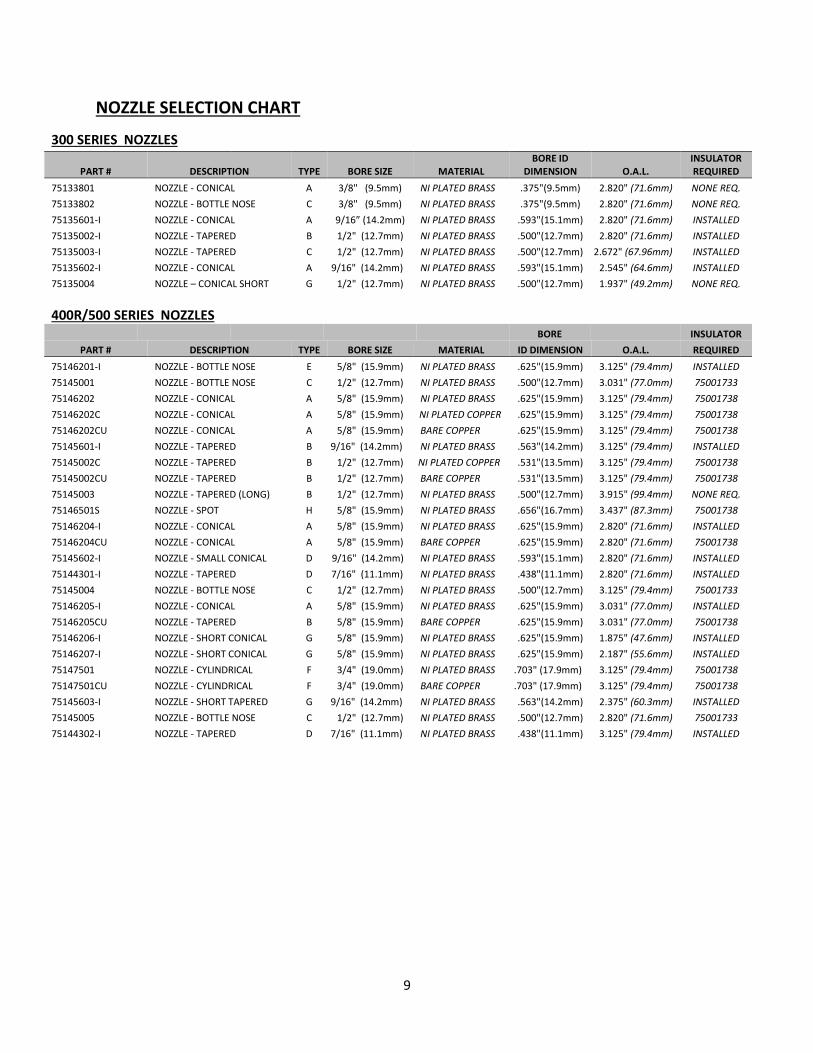
NOZZLE SELECTION CHART
300 SERIES NOZZLES
PART # DESCRIPTION TYPE BORE SIZE MATERIAL BORE ID
DIMENSION O.A.L. INSULATOR REQUIRED
75133801 NOZZLE - CONICAL A 3/8" (9.5mm) NI PLATED BRASS .375"(9.5mm) 2.820" (71.6mm) NONE REQ.
75133802 NOZZLE - BOTTLE NOSE C 3/8" (9.5mm) NI PLATED BRASS .375"(9.5mm) 2.820" (71.6mm) NONE REQ.
75135601-I NOZZLE - CONICAL A 9/16” (14.2mm) NI PLATED BRASS .593"(15.1mm) 2.820" (71.6mm) INSTALLED
75135002-I NOZZLE - TAPERED B 1/2" (12.7mm) NI PLATED BRASS .500"(12.7mm) 2.820" (71.6mm) INSTALLED
75135003-I NOZZLE - TAPERED C 1/2" (12.7mm) NI PLATED BRASS .500"(12.7mm) 2.672" (67.96mm) INSTALLED
75135602-I NOZZLE - CONICAL A 9/16" (14.2mm) NI PLATED BRASS .593"(15.1mm) 2.545" (64.6mm) INSTALLED
75135004 NOZZLE – CONICAL SHORT G 1/2" (12.7mm) NI PLATED BRASS .500"(12.7mm) 1.937" (49.2mm) NONE REQ.
400R/500 SERIES NOZZLES
BORE INSULATOR
PART # DESCRIPTION TYPE BORE SIZE MATERIAL ID DIMENSION O.A.L. REQUIRED 75146201-I NOZZLE - BOTTLE NOSE E 5/8" (15.9mm) NI PLATED BRASS .625"(15.9mm) 3.125" (79.4mm) INSTALLED 75145001 NOZZLE - BOTTLE NOSE C 1/2" (12.7mm) NI PLATED BRASS .500"(12.7mm) 3.031" (77.0mm) 75001733 75146202 NOZZLE - CONICAL A 5/8" (15.9mm) NI PLATED BRASS .625"(15.9mm) 3.125" (79.4mm) 75001738 75146202C NOZZLE - CONICAL A 5/8" (15.9mm) NI PLATED COPPER .625"(15.9mm) 3.125" (79.4mm) 75001738 75146202CU NOZZLE - CONICAL A 5/8" (15.9mm) BARE COPPER .625"(15.9mm) 3.125" (79.4mm) 75001738 75145601-I NOZZLE - TAPERED B 9/16" (14.2mm) NI PLATED BRASS .563"(14.2mm) 3.125" (79.4mm) INSTALLED 75145002C NOZZLE - TAPERED B 1/2" (12.7mm) NI PLATED COPPER .531"(13.5mm) 3.125" (79.4mm) 75001738 75145002CU NOZZLE - TAPERED B 1/2" (12.7mm) BARE COPPER .531"(13.5mm) 3.125" (79.4mm) 75001738 75145003 NOZZLE - TAPERED (LONG) B 1/2" (12.7mm) NI PLATED BRASS .500"(12.7mm) 3.915" (99.4mm) NONE REQ. 75146501S NOZZLE - SPOT H 5/8" (15.9mm) NI PLATED BRASS .656"(16.7mm) 3.437" (87.3mm) 75001738 75146204-I NOZZLE - CONICAL A 5/8" (15.9mm) NI PLATED BRASS .625"(15.9mm) 2.820" (71.6mm) INSTALLED 75146204CU NOZZLE - CONICAL A 5/8" (15.9mm) BARE COPPER .625"(15.9mm) 2.820" (71.6mm) 75001738 75145602-I NOZZLE - SMALL CONICAL D 9/16" (14.2mm) NI PLATED BRASS .593"(15.1mm) 2.820" (71.6mm) INSTALLED 75144301-I NOZZLE - TAPERED D 7/16" (11.1mm) NI PLATED BRASS .438"(11.1mm) 2.820" (71.6mm) INSTALLED 75145004 NOZZLE - BOTTLE NOSE C 1/2" (12.7mm) NI PLATED BRASS .500"(12.7mm) 3.125" (79.4mm) 75001733 75146205-I NOZZLE - CONICAL A 5/8" (15.9mm) NI PLATED BRASS .625"(15.9mm) 3.031" (77.0mm) INSTALLED 75146205CU NOZZLE - TAPERED B 5/8" (15.9mm) BARE COPPER .625"(15.9mm) 3.031" (77.0mm) 75001738 75146206-I NOZZLE - SHORT CONICAL G 5/8" (15.9mm) NI PLATED BRASS .625"(15.9mm) 1.875" (47.6mm) INSTALLED 75146207-I NOZZLE - SHORT CONICAL G 5/8" (15.9mm) NI PLATED BRASS .625"(15.9mm) 2.187" (55.6mm) INSTALLED 75147501 NOZZLE - CYLINDRICAL F 3/4" (19.0mm) NI PLATED BRASS .703" (17.9mm) 3.125" (79.4mm) 75001738 75147501CU NOZZLE - CYLINDRICAL F 3/4" (19.0mm) BARE COPPER .703" (17.9mm) 3.125" (79.4mm) 75001738 75145603-I NOZZLE - SHORT TAPERED G 9/16" (14.2mm) NI PLATED BRASS .563"(14.2mm) 2.375" (60.3mm) INSTALLED 75145005 NOZZLE - BOTTLE NOSE C 1/2" (12.7mm) NI PLATED BRASS .500"(12.7mm) 2.820" (71.6mm) 75001733 75144302-I NOZZLE - TAPERED D 7/16" (11.1mm) NI PLATED BRASS .438"(11.1mm) 3.125" (79.4mm) INSTALLED
10
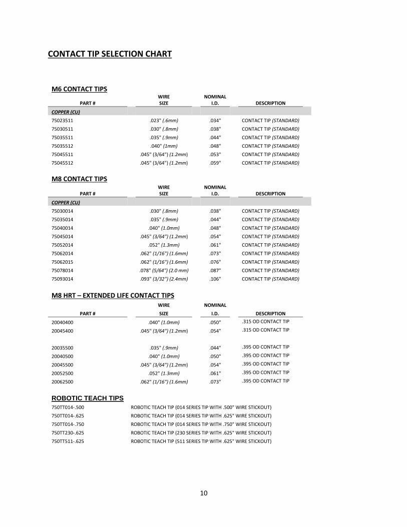
CONTACT TIP SELECTION CHART
M6 CONTACT TIPS
WIRE
NOMINAL
PART #
SIZE
I.D.
DESCRIPTION COPPER (CU)
75023511
.023" (.6mm)
.034"
CONTACT TIP (STANDARD) 75030511
.030" (.8mm)
.038"
CONTACT TIP (STANDARD)
75035511
.035" (.9mm)
.044"
CONTACT TIP (STANDARD) 75035512
.040" (1mm)
.048"
CONTACT TIP (STANDARD)
75045511
.045" (3/64") (1.2mm)
.053"
CONTACT TIP (STANDARD) 75045512
.045" (3/64") (1.2mm)
.059"
CONTACT TIP (STANDARD)
M8 CONTACT TIPS
WIRE
NOMINAL
PART #
SIZE
I.D.
DESCRIPTION COPPER (CU)
75030014
.030" (.8mm)
.038"
CONTACT TIP (STANDARD) 75035014
.035" (.9mm)
.044"
CONTACT TIP (STANDARD)
75040014
.040" (1.0mm)
.048"
CONTACT TIP (STANDARD) 75045014
.045" (3/64") (1.2mm)
.054"
CONTACT TIP (STANDARD)
75052014
.052" (1.3mm)
.061"
CONTACT TIP (STANDARD) 75062014
.062" (1/16") (1.6mm)
.073"
CONTACT TIP (STANDARD)
75062015
.062" (1/16") (1.6mm)
.076"
CONTACT TIP (STANDARD) 75078014
.078" (5/64") (2.0 mm)
.087"
CONTACT TIP (STANDARD)
75093014
.093" (3/32") (2.4mm)
.106"
CONTACT TIP (STANDARD)
M8 HRT – EXTENDED LIFE CONTACT TIPS
WIRE NOMINAL
PART # SIZE I.D. DESCRIPTION
20040400 .040" (1.0mm) .050" .315 OD CONTACT TIP
20045400 .045" (3/64") (1.2mm) .054" .315 OD CONTACT TIP
20035500 .035" (.9mm) .044" .395 OD CONTACT TIP
20040500 .040" (1.0mm) .050" .395 OD CONTACT TIP
20045500 .045" (3/64") (1.2mm) .054" .395 OD CONTACT TIP
20052500 .052" (1.3mm) .061" .395 OD CONTACT TIP
20062500 .062" (1/16") (1.6mm) .073" .395 OD CONTACT TIP
ROBOTIC TEACH TIPS
750TT014-.500 ROBOTIC TEACH TIP (014 SERIES TIP WITH .500" WIRE STICKOUT) 750TT014-.625 ROBOTIC TEACH TIP (014 SERIES TIP WITH .625" WIRE STICKOUT) 750TT014-.750 ROBOTIC TEACH TIP (014 SERIES TIP WITH .750" WIRE STICKOUT)
750TT230-.625 ROBOTIC TEACH TIP (230 SERIES TIP WITH .625" WIRE STICKOUT) 750TT511-.625 ROBOTIC TEACH TIP (511 SERIES TIP WITH .625" WIRE STICKOUT)
11
8
23
10
13
9
8a
11
14 15
16
21
8a
12
22
24
18
17
25 20
19
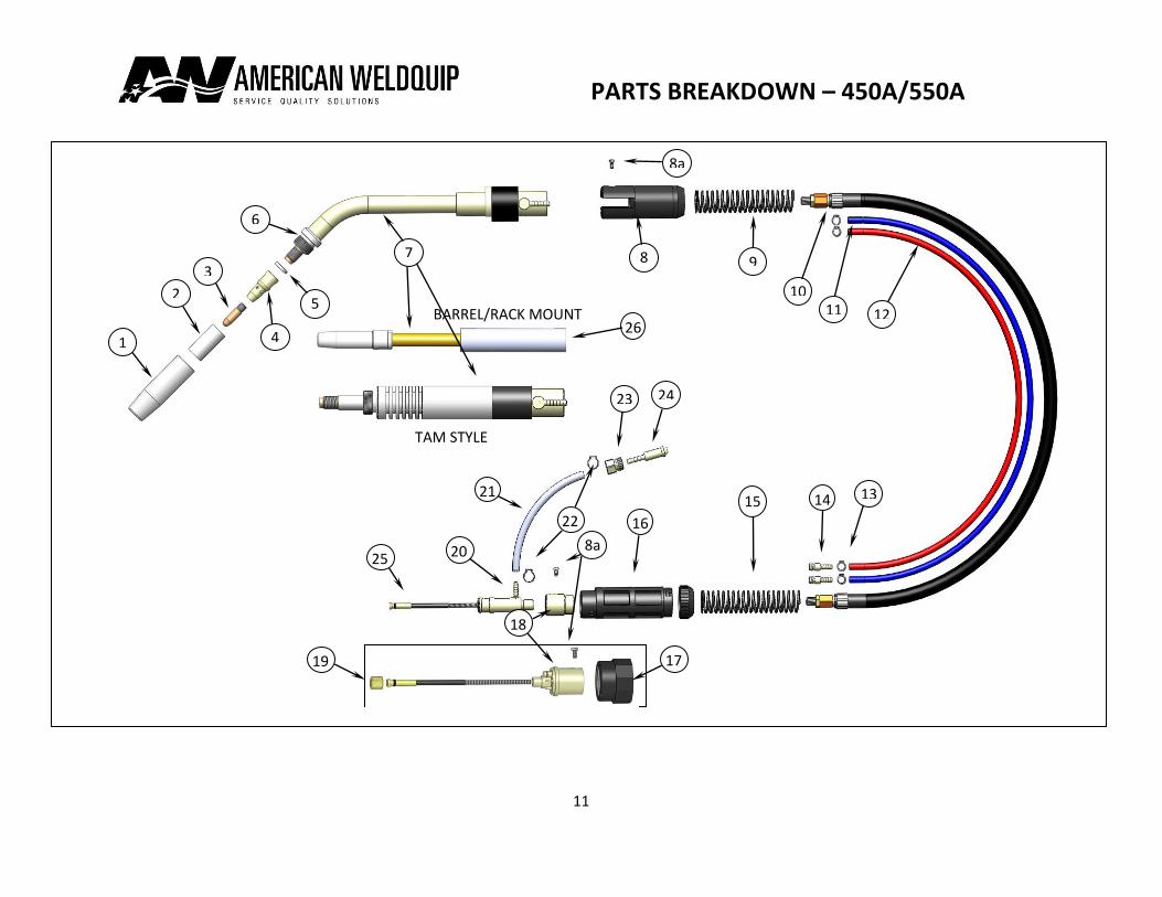
PARTS BREAKDOWN – 450A/550A
4
5
6
7
1
2
3
26
TAM STYLE
BARREL/RACK MOUNT
12
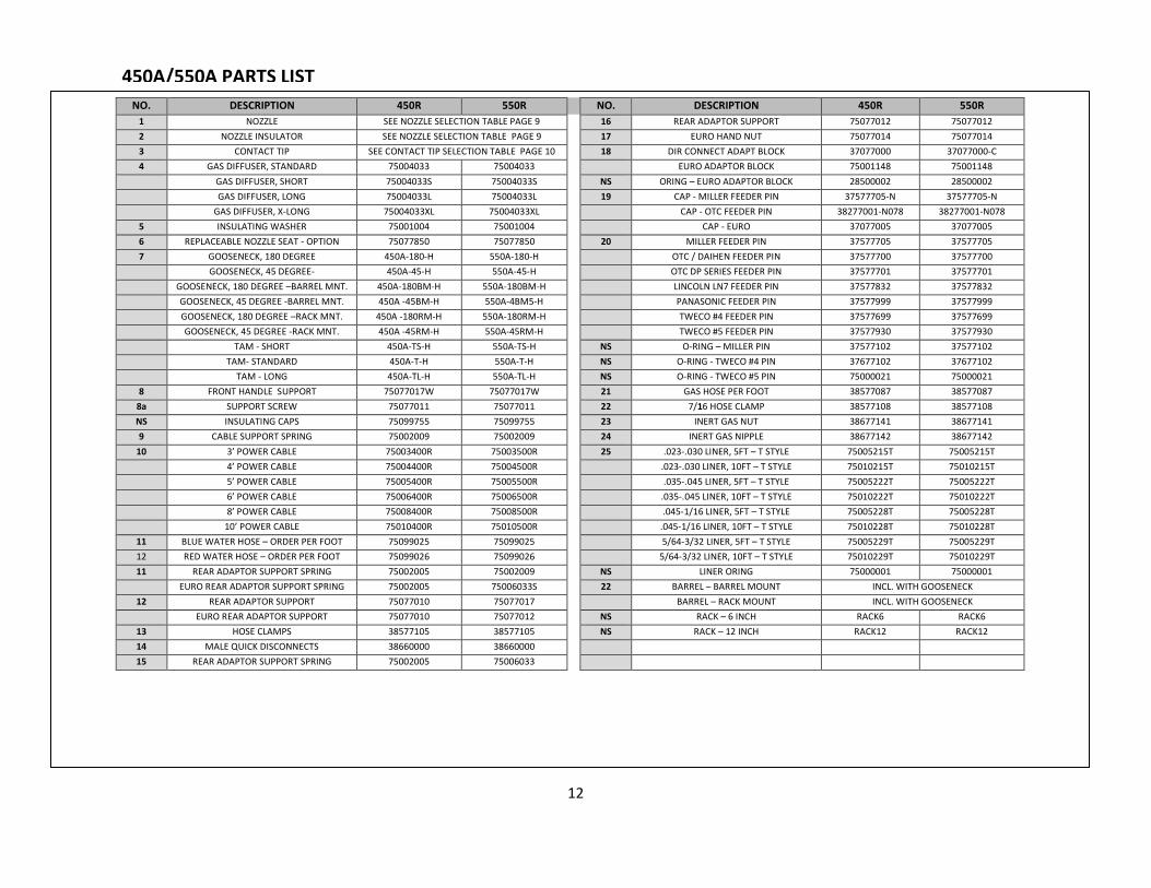
450A/550A PARTS LIST
NO. DESCRIPTION 450R 550R NO. DESCRIPTION 450R 550R
1 NOZZLE SEE NOZZLE SELECTION TABLE PAGE 9 16 REAR ADAPTOR SUPPORT 75077012 75077012
2 NOZZLE INSULATOR SEE NOZZLE SELECTION TABLE PAGE 9 17 EURO HAND NUT 75077014 75077014
3 CONTACT TIP SEE CONTACT TIP SELECTION TABLE PAGE 10 18 DIR CONNECT ADAPT BLOCK 37077000 37077000-C
4 GAS DIFFUSER, STANDARD 75004033 75004033 EURO ADAPTOR BLOCK 75001148 75001148
GAS DIFFUSER, SHORT 75004033S 75004033S NS ORING – EURO ADAPTOR BLOCK 28500002 28500002
GAS DIFFUSER, LONG 75004033L 75004033L 19 CAP - MILLER FEEDER PIN 37577705-N 37577705-N
GAS DIFFUSER, X-LONG 75004033XL 75004033XL CAP - OTC FEEDER PIN 38277001-N078 38277001-N078
5 INSULATING WASHER 75001004 75001004 CAP - EURO 37077005 37077005
6 REPLACEABLE NOZZLE SEAT - OPTION 75077850 75077850 20 MILLER FEEDER PIN 37577705 37577705
7 GOOSENECK, 180 DEGREE 450A-180-H 550A-180-H OTC / DAIHEN FEEDER PIN 37577700 37577700
GOOSENECK, 45 DEGREE- 450A-45-H 550A-45-H OTC DP SERIES FEEDER PIN 37577701 37577701
GOOSENECK, 180 DEGREE –BARREL MNT. 450A-180BM-H 550A-180BM-H LINCOLN LN7 FEEDER PIN 37577832 37577832
GOOSENECK, 45 DEGREE -BARREL MNT. 450A -45BM-H 550A-4BM5-H PANASONIC FEEDER PIN 37577999 37577999
GOOSENECK, 180 DEGREE –RACK MNT. 450A -180RM-H 550A-180RM-H TWECO #4 FEEDER PIN 37577699 37577699
GOOSENECK, 45 DEGREE -RACK MNT. 450A -45RM-H 550A-45RM-H TWECO #5 FEEDER PIN 37577930 37577930
TAM - SHORT 450A-TS-H 550A-TS-H NS O-RING – MILLER PIN 37577102 37577102
TAM- STANDARD 450A-T-H 550A-T-H NS O-RING - TWECO #4 PIN 37677102 37677102
TAM - LONG 450A-TL-H 550A-TL-H NS O-RING - TWECO #5 PIN 75000021 75000021
8 FRONT HANDLE SUPPORT 75077017W 75077017W 21 GAS HOSE PER FOOT 38577087 38577087
8a SUPPORT SCREW 75077011 75077011 22 7/16 HOSE CLAMP 38577108 38577108
NS INSULATING CAPS 75099755 75099755 23 INERT GAS NUT 38677141 38677141
9 CABLE SUPPORT SPRING 75002009 75002009 24 INERT GAS NIPPLE 38677142 38677142
10 3’ POWER CABLE 75003400R 75003500R 25 .023-.030 LINER, 5FT – T STYLE 75005215T 75005215T
4’ POWER CABLE 75004400R 75004500R .023-.030 LINER, 10FT – T STYLE 75010215T 75010215T
5’ POWER CABLE 75005400R 75005500R .035-.045 LINER, 5FT – T STYLE 75005222T 75005222T
6’ POWER CABLE 75006400R 75006500R .035-.045 LINER, 10FT – T STYLE 75010222T 75010222T
8’ POWER CABLE 75008400R 75008500R .045-1/16 LINER, 5FT – T STYLE 75005228T 75005228T
10’ POWER CABLE 75010400R 75010500R .045-1/16 LINER, 10FT – T STYLE 75010228T 75010228T
11 BLUE WATER HOSE – ORDER PER FOOT 75099025 75099025 5/64-3/32 LINER, 5FT – T STYLE 75005229T 75005229T
12 RED WATER HOSE – ORDER PER FOOT 75099026 75099026 5/64-3/32 LINER, 10FT – T STYLE 75010229T 75010229T
11 REAR ADAPTOR SUPPORT SPRING 75002005 75002009 NS LINER ORING 75000001 75000001
EURO REAR ADAPTOR SUPPORT SPRING 75002005 75006033S 22 BARREL – BARREL MOUNT INCL. WITH GOOSENECK
12 REAR ADAPTOR SUPPORT 75077010 75077017 BARREL – RACK MOUNT INCL. WITH GOOSENECK
EURO REAR ADAPTOR SUPPORT 75077010 75077012 NS RACK – 6 INCH RACK6 RACK6
13 HOSE CLAMPS 38577105 38577105 NS RACK – 12 INCH RACK12 RACK12
14 MALE QUICK DISCONNECTS 38660000 38660000
15 REAR ADAPTOR SUPPORT SPRING 75002005 75006033
13
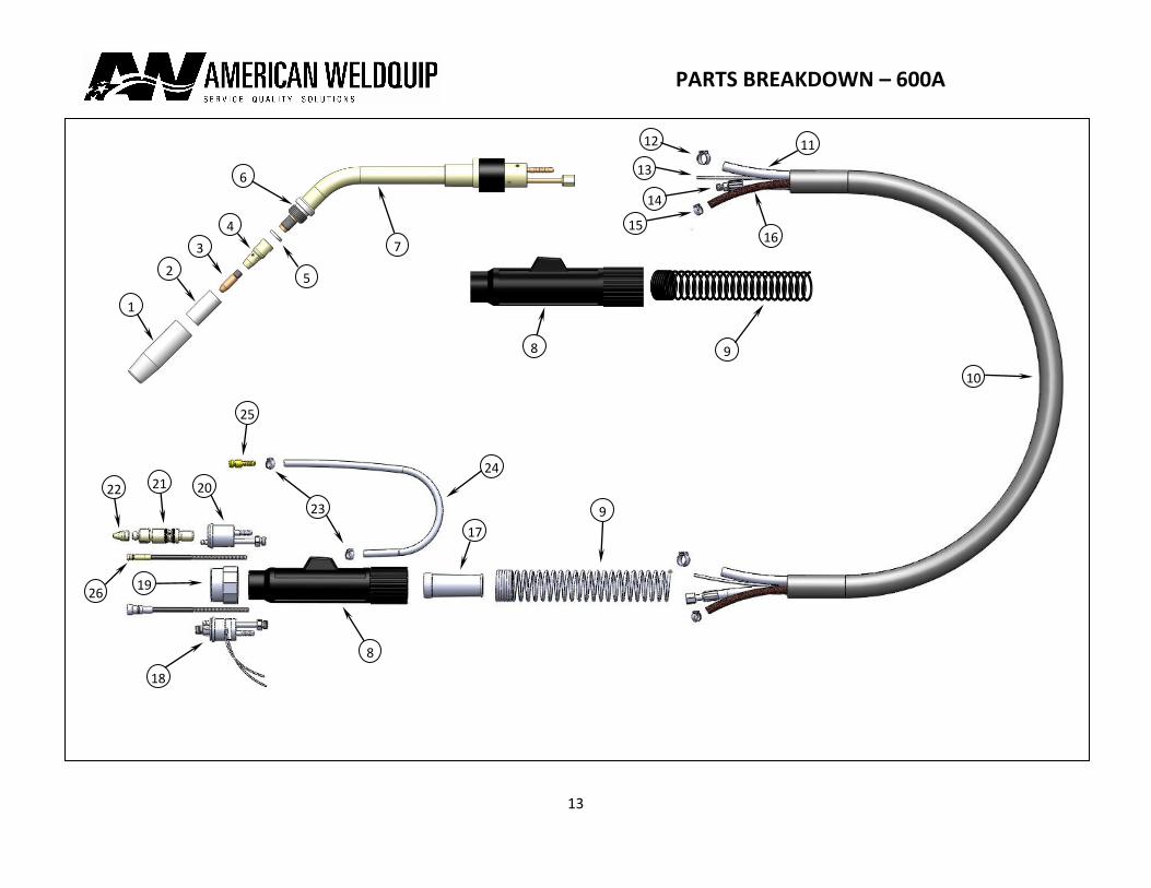
PARTS BREAKDOWN – 600A
1
2
7 3
4
5
6
11
10
16
17
15
14
12
13
26
9 23
19
18
21 22 20
25
24
8
8 9
14
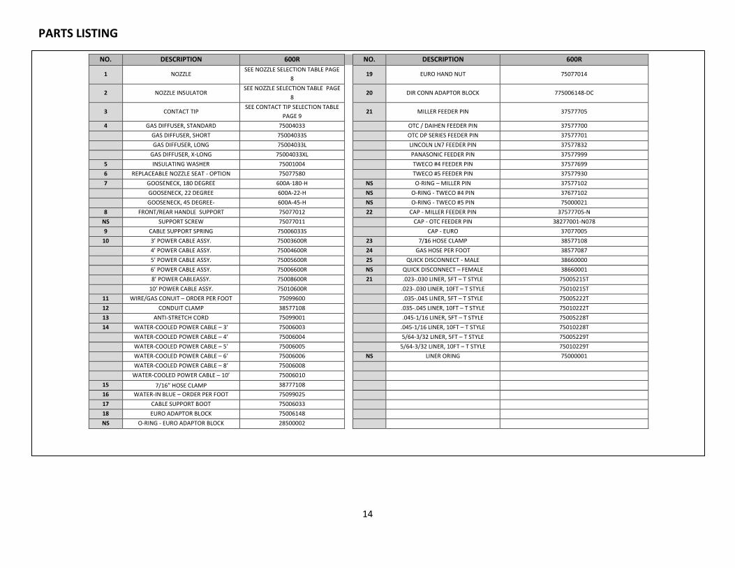
600R PARTS LIST
NO. DESCRIPTION 600R NO. DESCRIPTION 600R
1 NOZZLE SEE NOZZLE SELECTION TABLE PAGE
8 19 EURO HAND NUT 75077014
2 NOZZLE INSULATOR SEE NOZZLE SELECTION TABLE PAGE
8 20 DIR CONN ADAPTOR BLOCK 775006148-DC
3 CONTACT TIP SEE CONTACT TIP SELECTION TABLE
PAGE 9 21 MILLER FEEDER PIN 37577705
4 GAS DIFFUSER, STANDARD 75004033 OTC / DAIHEN FEEDER PIN 37577700
GAS DIFFUSER, SHORT 75004033S OTC DP SERIES FEEDER PIN 37577701
GAS DIFFUSER, LONG 75004033L LINCOLN LN7 FEEDER PIN 37577832
GAS DIFFUSER, X-LONG 75004033XL PANASONIC FEEDER PIN 37577999
5 INSULATING WASHER 75001004 TWECO #4 FEEDER PIN 37577699
6 REPLACEABLE NOZZLE SEAT - OPTION 75077580 TWECO #5 FEEDER PIN 37577930
7 GOOSENECK, 180 DEGREE 600A-180-H NS O-RING – MILLER PIN 37577102
GOOSENECK, 22 DEGREE 600A-22-H NS O-RING - TWECO #4 PIN 37677102
GOOSENECK, 45 DEGREE- 600A-45-H NS O-RING - TWECO #5 PIN 75000021
8 FRONT/REAR HANDLE SUPPORT 75077012 22 CAP - MILLER FEEDER PIN 37577705-N
NS SUPPORT SCREW 75077011 CAP - OTC FEEDER PIN 38277001-N078
9 CABLE SUPPORT SPRING 75006033S CAP - EURO 37077005
10 3’ POWER CABLE ASSY. 75003600R 23 7/16 HOSE CLAMP 38577108
4’ POWER CABLE ASSY. 75004600R 24 GAS HOSE PER FOOT 38577087
5’ POWER CABLE ASSY. 75005600R 25 QUICK DISCONNECT - MALE 38660000
6’ POWER CABLE ASSY. 75006600R NS QUICK DISCONNECT – FEMALE 38660001
8’ POWER CABLEASSY. 75008600R 21 .023-.030 LINER, 5FT – T STYLE 75005215T
10’ POWER CABLE ASSY. 75010600R .023-.030 LINER, 10FT – T STYLE 75010215T
11 WIRE/GAS CONUIT – ORDER PER FOOT 75099600 .035-.045 LINER, 5FT – T STYLE 75005222T
12 CONDUIT CLAMP 38577108 .035-.045 LINER, 10FT – T STYLE 75010222T
13 ANTI-STRETCH CORD 75099001 .045-1/16 LINER, 5FT – T STYLE 75005228T
14 WATER-COOLED POWER CABLE – 3’ 75006003 .045-1/16 LINER, 10FT – T STYLE 75010228T
WATER-COOLED POWER CABLE – 4’ 75006004 5/64-3/32 LINER, 5FT – T STYLE 75005229T
WATER-COOLED POWER CABLE – 5’ 75006005 5/64-3/32 LINER, 10FT – T STYLE 75010229T
WATER-COOLED POWER CABLE – 6’ 75006006 NS LINER ORING 75000001
WATER-COOLED POWER CABLE – 8’ 75006008
WATER-COOLED POWER CABLE – 10’ 75006010
15 7/16” HOSE CLAMP 38777108
16 WATER-IN BLUE – ORDER PER FOOT 75099025
17 CABLE SUPPORT BOOT 75006033
18 EURO ADAPTOR BLOCK 75006148
NS O-RING - EURO ADAPTOR BLOCK 28500002
PARTS LISTING

15
NO
TES:

16
1375 Wolf Creek Trail – P.O. Box 397
Sharon Center, Ohio 44274
330-239-0317 Telephone / 800-949-9353 Fax
OM012 – 05/14