www.infotech.monash.edu fit 1005 networks & data communications lecture 7 – multiplexing...
TRANSCRIPT

www.infotech.monash.edu
FIT 1005 Networks & Data Communications
Lecture 7 – MultiplexingLecture 7 – Multiplexing
Reference: Chapter 8
Data and Computer Communications
Eighth Edition
by William Stallings
Lecture slides by Lawrie Brown
Updated / modified slides : http://users.monash.edu.au/~amkhan/fit1005

www.infotech.monash.edu
2
Multiplexing
• Multiplexing is the process where multiple channels are combined for transmission over a common transmission path.
• Full capacity of data transmission links are not always fully utilized
• To make efficient use of high-speed telecommunications lines, some form of multiplexing is used
• common application of multiplexing is done in long-haul communications.

www.infotech.monash.edu
3
Multiplexing – in long-haul communications.

www.infotech.monash.edu
4
Multiplexing
• Trunks on long-haul networks are high-capacity fiber, coaxial, or microwave links.
• These links can carry large numbers of voice and data transmissions simultaneously using multiplexing.
• Common forms of multiplexing are:
– Frequency Division Multiplexing (FDM),
– Time Division Multiplexing (TDM), and
– Statistical TDM (STDM).
– Wave Division Multiplexing (WDM)
Multiplexing
Analog Digital
FDM WDM (S)TDM

www.infotech.monash.edu
5
Multiplexing
• multiple n inputs / 1 outputs on 1 physical line• multiplexing allows several transmission sources
to share a larger transmission capacity• the link can carry multiple channels of data• common on long-haul, high capacity, links

www.infotech.monash.edu
6
Frequency Division Multiplexing
• Division of a transmission link into multiple channels by splitting the frequency band into multiple slots.
• Used when useful bandwidth of the link is greater than required bandwidth of individual signals to be transmitted.
• Each signal is modulated on a different carrier frequency.• Carrier frequencies are centered at each signal BW and
typically separated by guard bands so that signals do not overlap.
• An FDM receiver uses filters, one per slot, to separate the individual channels, each of which is separately demodulated to extract the signal.

www.infotech.monash.edu
7
Frequency Division Multiplexing

www.infotech.monash.edu
8
FDMSystem Overview
m n(t)D to A
FDM animation
http://www.netbook.cs.purdue.edu/animations/fdm.html

FDM System - A conceptual illustration of the multiplexing and de-multiplexing process.
Each source generates a signal of a similar frequency range.
Each source generates a signal of a similar frequency range.
This results in composite baseband modulating signal that is sent out over a media link that has enough bandwidth to accommodate it.
This results in composite baseband modulating signal that is sent out over a media link that has enough bandwidth to accommodate it.
The de-multiplexer uses a series of filters to decompose the multiplexed signal into itsconstituent component signals.
The de-multiplexer uses a series of filters to decompose the multiplexed signal into itsconstituent component signals.
The individual signals are then passed to a demodulatorthat separates them from their carriers and passes them to the output lines
The individual signals are then passed to a demodulatorthat separates them from their carriers and passes them to the output lines
at Transmitter at Receiver
Multiplexer modulates these similar source signals with different subcarrier frequencies (f1, f2, and f3)
Multiplexer modulates these similar source signals with different subcarrier frequencies (f1, f2, and f3)
www.infotech.monash.edu
10
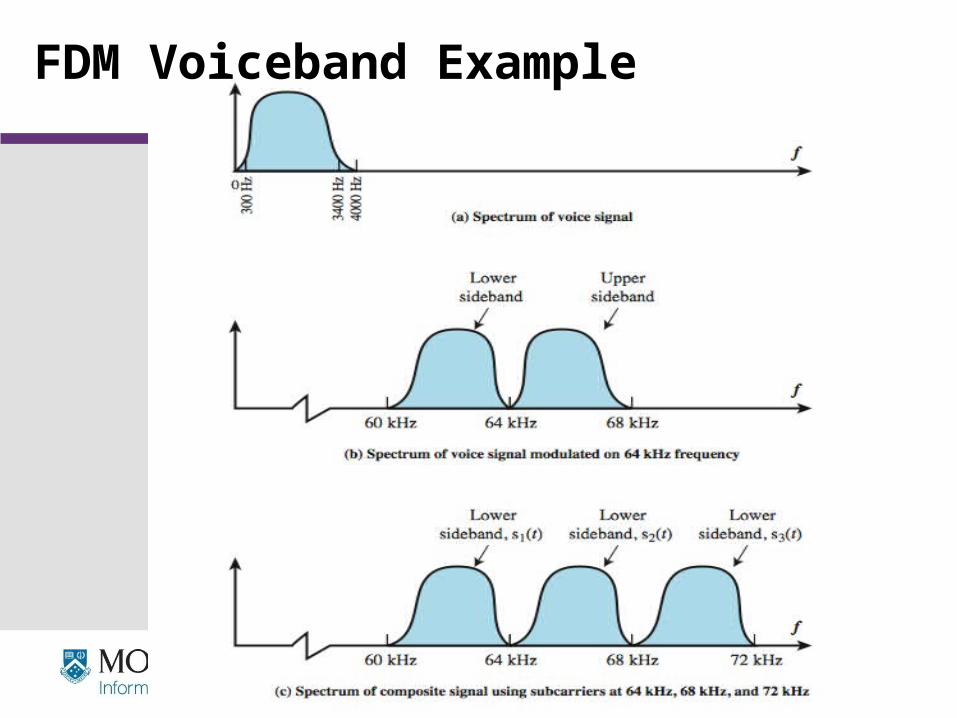
FDM Voiceband Example

www.infotech.monash.edu
11
Analog Carrier Systems
• long-distance links use an FDM hierarchy• AT&T (USA) and ITU-T (International) variants
• Group– 12 voice channels (4kHz each) = 48kHz - bandwidth– in range 60kHz to 108kHz
• Supergroup– FDM of 5 group signals supports 12 x 5 = 60 channels– 48 x 48kHz = 240kHz - BandWidth– on carriers between 312kHz and 552 kHz
• Mastergroup– FDM of 10 supergroup supports 60 x 10 = 600 channels
• so original signal can be modulated many times

www.infotech.monash.edu
12
Wavelength Division Multiplexing
• FDM with multiple beams of light at different frequencies
• WDM carried over optical fiber links uses λ wavelength– commercial systems with 160 channels of 10 Gbps– lab demo of 256 channels 39.8 Gbps
• Architecture similar to other FDM systems– multiplexer consolidates laser sources (1550nm)
of different λ ‘s for transmission over single fiber– Optical amplifiers amplify all wavelengths– Demux separates channels at the destination
• There are two types of WDM, namely:– Coarse WDM (CWDM) - here the wavelengths are spaced well apart– Dense WDM (DWDM) - here larger number of closely spaced wavelengths

www.infotech.monash.edu
13
Synchronous Time Division Multiplexing
• Time slots on a shared medium are assigned to devices on a fixed, predetermined basis
www.infotech.monash.edu
14
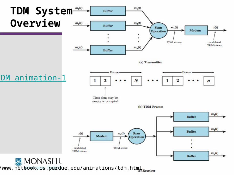
TDM SystemOverview
TDM animation-1
http://www.netbook.cs.purdue.edu/animations/tdm.html

www.infotech.monash.edu
15
TDM Link Control
• no headers and trailers• data link control protocols (flow & error) not needed• flow control
– data rate of multiplexed line is fixed
– if one channel receiver cannot receive data, the others must carry on
– corresponding source must be quenched
– leaving empty slots
– so no flow control needed
• error control– errors detected & handled on individual channel or Per-
channel basis

www.infotech.monash.edu
16
Data Link Control on TDM
HDLC frame per channel basis

www.infotech.monash.edu
17
Framing
• no flag or SYNC chars bracketing TDM frames• must still provide synchronizing mechanism
between src and dest clocks• added digit framing
– one control bit added to each TDM frame– identifiable bit pattern used on control channel– eg. alternating 01010101…unlikely on a data channel– compare incoming bit patterns on each channel with known
sync pattern
www.infotech.monash.edu
18
Pulse Stuffing
• have problem of synchronizing various data sources• with clocks in different sources drifting• also issue of data rates from different sources not related by
simple rational number• Pulse Stuffing a common solution
– to have outgoing data rate (excluding framing bits) higher than sum of incoming rates
– by stuffing extra dummy bits or pulses into each incoming signal until it matches the local clock
– stuffed pulses inserted at fixed locations in frame and are removed at the de-multiplexer

www.infotech.monash.edu
19
TDM Example with pulse stuffing

www.infotech.monash.edu
20
Digital Carrier Systems
• long-distance links use an TDM hierarchy• AT&T (USA) and ITU-T (International) two variants• US system based on DS-1 format• can carry mixed voice and data signals• 24 channels used for total data rate 1.544Mbps (193 x 8000
samples/sec)• each voice channel contains one word of digitized data (PCM,
8000 samples per sec)• same format for 56kbps digital data• can interleave DS-1 channels for higher rates
– DS-1 is 24 channels at 1.544 Mbps– DS-2 is four DS-1 at 6.312Mbps– DS-3 is eight DS-1 at 44.736 Mbps

www.infotech.monash.edu
21
DS-1 Transmission Format
The first bit is used as framing bit, this is used for synchronization.
For Voice Channels:1. For five of every six frames, 8-bit PCM samples are used, and 2. For every sixth frame, each channel contains a 7-bit PCM + 1-bit for signalling
(contains network control and routing information)
For Data Channels:1. 23 Channel are used for data and Channel-24 is used for signalling.2. If 7 bits used per channel i.e. Bits 1 to 7 are used for data then each channel can
achieve (7bits x 8000 frames/sec =56 kbps)3. If 6 bits are used per channel i.e. Bits 2 to 7 are used for data then each channel
can achieve ( 6bits x 8000 frames/sec = 48 kbps ). • By multiplexing we can achieve 5 x 9.6 kbps, 10 x 4.8 kbps, or 20 x 2.4 kbps.

www.infotech.monash.edu
22
Statistical TDM
• In Synch TDM many slots are wasted• Statistical TDM allocates time slots dynamically
based on demand• multiplexer scans input lines and collects data until
frame full• line data rate lower than aggregate input line rates • may have problems during peak periods
– must buffer inputs
www.infotech.monash.edu
23
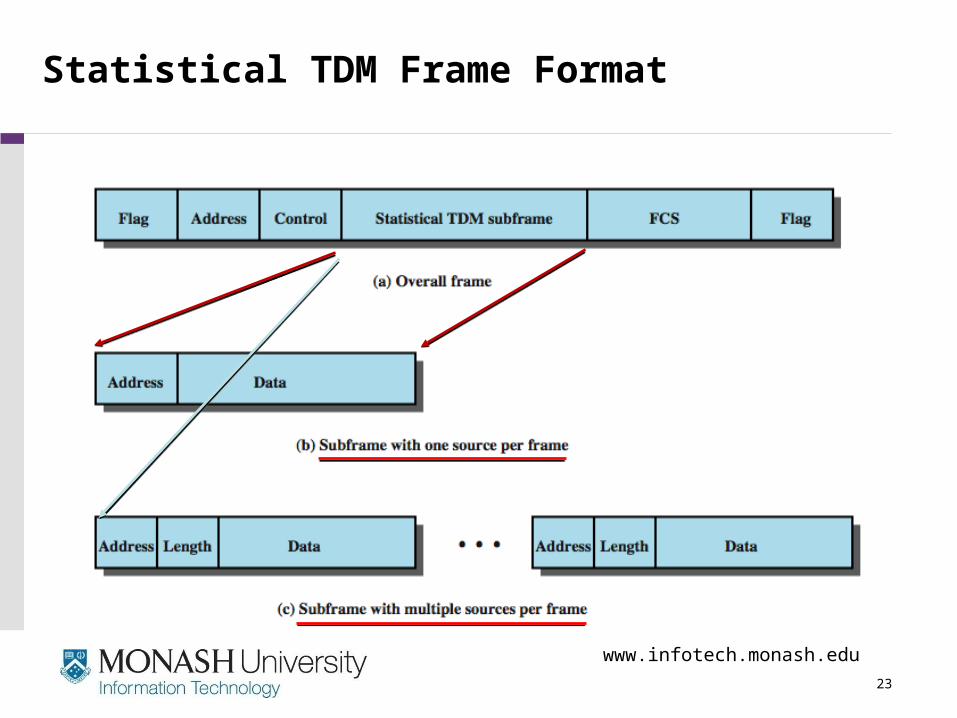
Statistical TDM Frame Format

www.infotech.monash.edu
24
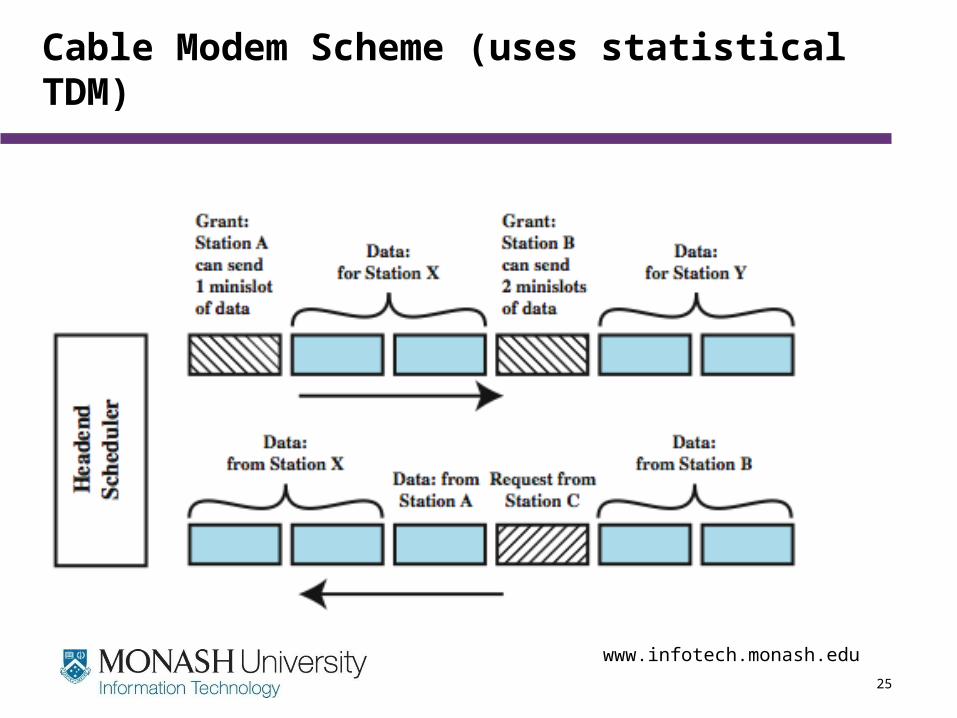
Cable Modems
• To support full duplex data transfer two cable TV
channels are reserved
• each channel is shared by a number of subscribers, using statistical TDM
• Downstream channel– cable scheduler delivers data in small packets– active subscribers share downstream capacity– also allocates upstream time slots to subscribers
• Upstream channel– user requests timeslots on shared upstream channel– Head-end scheduler notifies subscriber of slots to use
www.infotech.monash.edu
25
Cable Modem Scheme (uses statistical TDM)

www.infotech.monash.edu
26
Asymmetrical Digital Subscriber Line (ADSL)
• link between subscriber and network• uses currently installed twisted pair telephone cable• It is Asymmetric - bigger downstream than upstream• uses Frequency division multiplexing (FDM)
– reserve lowest 25kHz for voice - Plain old telephone service (POTS)
– uses echo cancellation or FDM to get two distinct bands
• has a range of up to 5.5km

www.infotech.monash.edu
27
ADSL Channel Configuration
Uses – 2 techniques for internet access (data):
1.Echo cancellation : A signal processing technique
– allow transmission of digital signals in both direction, single line simultaneously
2.FDM to allocate two bands – Upstream and Downstream
Uses channel separation i.e. FDM exploit the 1-MHz capacity of twisted
pair 0-20KHz for voice POTS i.e. Only 0-
4khz for voice and rest for guard band Remaining 25KHz - 1000KHz of the BW
for data upload and download streams

www.infotech.monash.edu
28
Discrete Multitone (DMT)
• Uses multiple carrier signals at different frequencies• Bandwidth(BW) is divided into 4kHz of sub-channels• DMT modems tests and uses sub-channels with better SNR• DMT modem assigns more data to channels with large SNR’s• ADSL / DMT both design & employ 256 downstream sub-channels
at 4kHz (each channel 0 - 60kbps)– in theory (256 x 60kbps)=15.36Mbps, in practice 1.5 - 9Mbps

www.infotech.monash.edu
29
DMT Transmitter
Input bit stream
Input bit stream is Divided into multiplesub-streams
Each sub-stream is then converted to an Analog signal using Quadrature amplitude modulation
(QAM),
Each sub-stream is then converted to an Analog signal using Quadrature amplitude modulation
(QAM),

www.infotech.monash.edu
30
xDSL
• High data rate DSL (HDSL)– 2B1Q coding on dual twisted pairs (2B1Q means that two bits are
combined to form a single Quaternary line state symbol one of four signal levels on the line)
– up to 2Mbps over 3.7km
• Single line DSL (SDSL)– 2B1Q coding on single twisted pair (residential) with echo
cancelling– up to 2Mbps over 3.7km
• Very high data rate DSL (VDSL)– DMT/QAM for very high data rates– over separate bands for separate services

www.infotech.monash.edu
31
Summary
• looked at multiplexing multiple channels on a single link
• FDM• TDM• Statistical TDM• ADSL and xDSL

www.infotech.monash.edu
32
Term Line Rate Also known asE1 2.048 Mbps
T1 1.544 Mbps (24 x 64 kbps) DS1
T2 6.312 Mbps DS2
T3 44.736 Mbps DS3Ethernet 10 Mbps Fast Ethernet 100 Mbps Token Ring 4 or 16 Mbps DS0 64 kbps DS1 1.544 Mbps T1DS2 6.312 Mbps T2DS3 44.736 Mbps T3OC-1 51.84 Mbps STS-1OC-3 155.52 Mbps STS-3 & STM-1OC-12 622.08 Mbps STS-12 & STM-4OC-24 1244.16 Mbps STS-24 & STM-8OC-48 2488.32 Mbps STS-48 & STM-16OC-96 4976.64 Mbps STS-96 & STM-32OC-192 9953.28 Mbps STS-192 & STM-64ISDN Basic (2B+D) 2 x 64 kbps & 1 x 16 kbps ISDN B Channel 64 kbps ISDN D Channel 16 kbps ISDN Signalling ChannelISDN Primary (24B+D) 24 x 64 kbps & 1 x 16 kbps Sonet 51.84 Mbps - 10 Gbps SDH 155 Mbps - 10 Gbps PDH T1/E1 - 565 Mbps