www.isocore.com/mpls2013 a new paradigm for inter-domain traffic engineering adrian farrel juniper...
TRANSCRIPT

www.isocore.com/mpls2013
A New Paradigm for Inter-Domain Traffic Engineering
Adrian FarrelJuniper Networks

2
Multi-Domain Traffic Engineering
• Traffic Engineering optimization is an end-to-end function• The best path in one domain may yield a sub-optimal
end-to-end path• Implies…
• need for visibility of multi-domain TE information when computing paths
• …or…• Some form of brokering or arbitrage

3
TE Optimization and Computation
• Traffic Engineering can optimise for a complex set of metrics and functions• This used to be just
• Connectivity• Metric• Bandwidth
• Now becoming significantly more complicated• SRLG• Delay• Optical parameters
• Computation is an “interesting” problem• Trading different metrics• Non-linear constraints
4
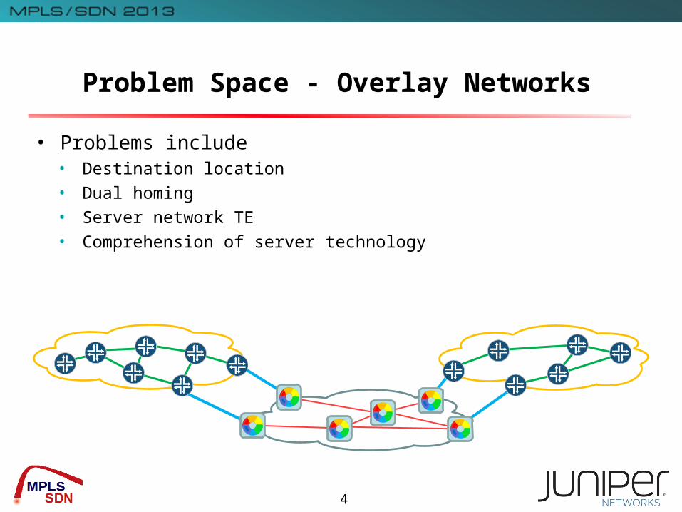
Problem Space - Overlay Networks
• Problems include• Destination location• Dual homing• Server network TE• Comprehension of server technology

5
Problem Space - Peer Networks
• Provision an end-to-end service across multiple domains• Example: Multi-site VPN over connected Ases
• Problems are:• Location of target domain• Choice of domains to traverse• Choice of points of attachment• Paths within each core network
VPN Site A
VPN Site D
VPN Site CVPN Site B
Core Network X
Core Network Z
Core Network Y

6
UNI - The Blind Leading the Blind • Interface between the client and server network
• Request connectivity
• Clearly useful: implemented and deployed
• Significant limitations
• Blind to the server network : can’t see topology or reachability
• Not a service request interface
• Many proposals to add function to the UNI• Can we evolve or is this a blind alley?
UNI

7
Flooding Would Be Crazy
Well, it would, wouldn’t it?
Flooding means…• Telling the client network about all of the links
and nodes in the server network• A shared IGP• Two IGP instances• GMPLS actually supports this
Networks usually under different administrations
Scaling is a real concern
It can get messy with multiple server networks
Client network will not understand server links• All those optical parameters etc.• Really don’t want to try to send packets down optical links
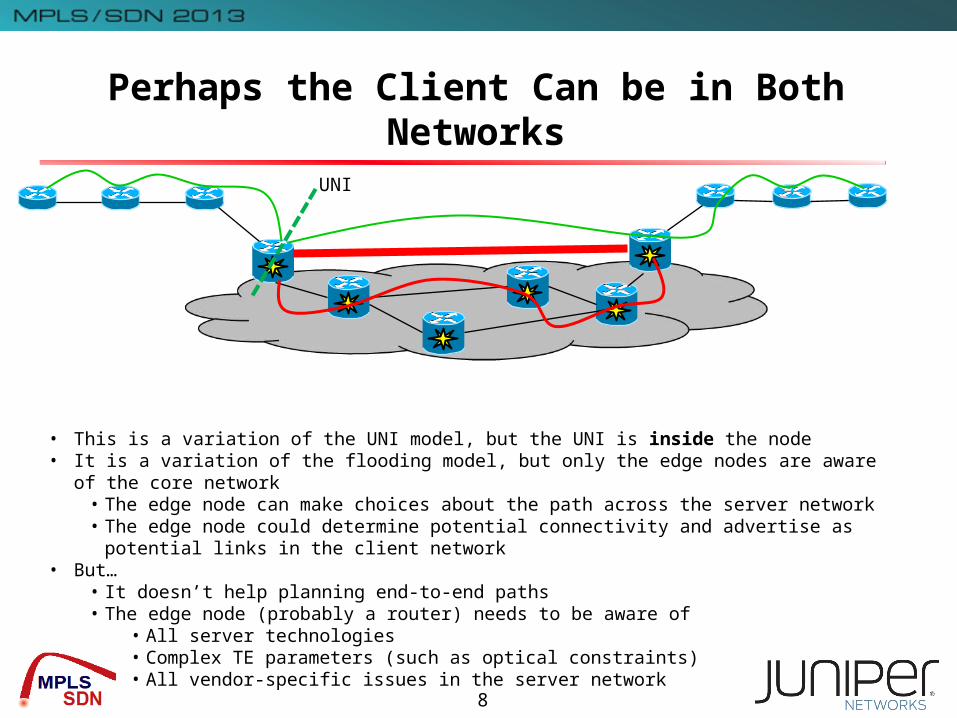
Perhaps the Client Can be in Both Networks
• This is a variation of the UNI model, but the UNI is inside the node• It is a variation of the flooding model, but only the edge nodes are aware of the core
network• The edge node can make choices about the path across the server network• The edge node could determine potential connectivity and advertise as potential links in
the client network• But…
• It doesn’t help planning end-to-end paths• The edge node (probably a router) needs to be aware of
• All server technologies• Complex TE parameters (such as optical constraints)• All vendor-specific issues in the server network
UNI
8
9
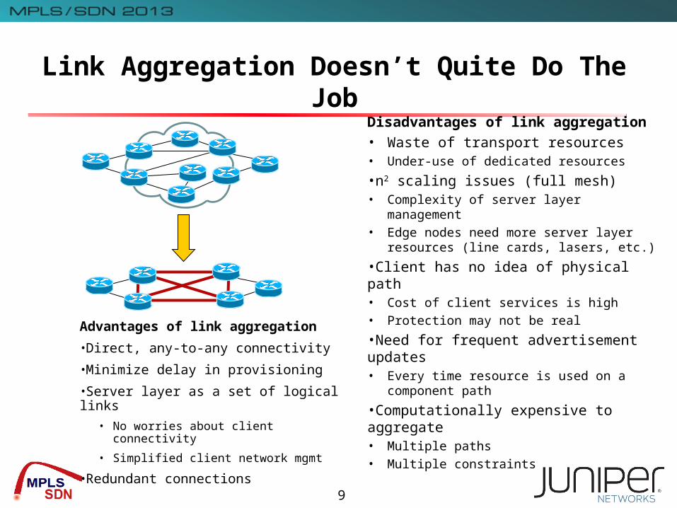
Link Aggregation Doesn’t Quite Do The Job
Advantages of link aggregation
•Direct, any-to-any connectivity
•Minimize delay in provisioning
•Server layer as a set of logical links
• No worries about client connectivity
• Simplified client network mgmt
•Redundant connections
Disadvantages of link aggregation• Waste of transport resources• Under-use of dedicated resources
•n2 scaling issues (full mesh)• Complexity of server layer management
• Edge nodes need more server layer resources (line cards, lasers, etc.)
•Client has no idea of physical path• Cost of client services is high
• Protection may not be real
•Need for frequent advertisement updates• Every time resource is used on a component
path
•Computationally expensive to aggregate• Multiple paths
• Multiple constraints

10
Node Aggregation Doesn’t Cut it Either
Advantages of AggregationVery simple modelScales wellDoes not need frequent updates
Disadvantages of aggregation•No consideration of path properties•No visibility into disjoint paths•Limited cross-connect ability is hidden
• In particular when network is partitioned
• Issues with wavelength continuity
•There are ways to handle limited cross-connects in GMPLS advertisements, but higher layer network will not understand them
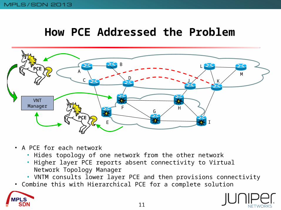
How PCE Addressed the Problem
AL
M
KJ
I
HG
E
F
C
B
D
VNT Manager
PCE
• A PCE for each network• Hides topology of one network from the other network• Higher layer PCE reports absent connectivity to Virtual Network
Topology Manager• VNTM consults lower layer PCE and then provisions connectivity
• Combine this with Hierarchical PCE for a complete solution
PCE
11
New Architectural Tools
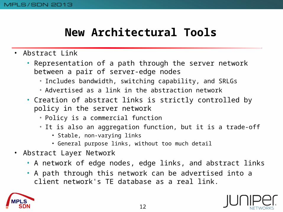
• Abstract Link• Representation of a path through the server network between a pair
of server-edge nodes• Includes bandwidth, switching capability, and SRLGs
• Advertised as a link in the abstraction network
• Creation of abstract links is strictly controlled by policy in the server network
• Policy is a commercial function
• It is also an aggregation function, but it is a trade-off• Stable, non-varying links• General purpose links, without too much detail
• Abstract Layer Network• A network of edge nodes, edge links, and abstract links• A path through this network can be advertised into a client network's
TE database as a real link.
12

Architectural Overview
Client Network
Server Network
Abstraction Network
e2e client LSP
(potential) Server LSP
Abstract link
(potential or actual) Client link
13
14
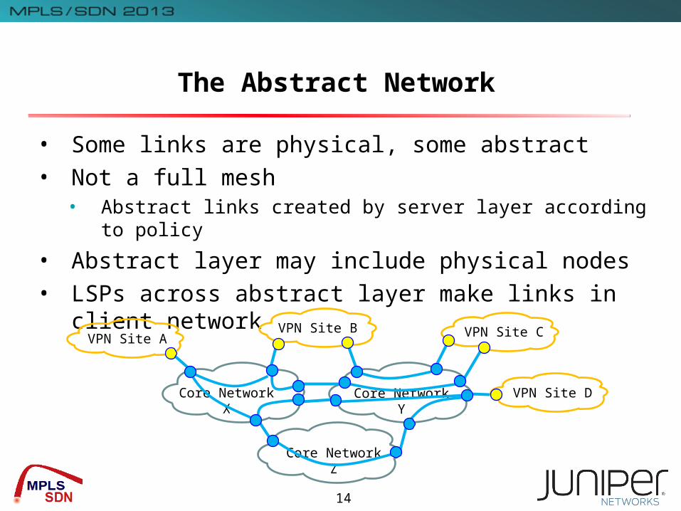
The Abstract Network
• Some links are physical, some abstract• Not a full mesh
• Abstract links created by server layer according to policy
• Abstract layer may include physical nodes• LSPs across abstract layer make links in client network
VPN Site A
VPN Site D
VPN Site CVPN Site B
Core Network X
Core Network Z
Core Network Y
Why Three Layers and What Role for Routing?
• The Abstraction Layer provides separation• Protects client from knowledge of server technology• Hides complexity of interconnected server networks• Allows client link creation to be separated from means of connectivity• Facilitates different provisioning techniques
• Control plane• Management system• SDN (“Transport SDN”)
• Abstraction layer is a simple network• Can run its own instance of an IGP
• Topology export at border nodes• A function of policy• Could use BGP-LS• Maybe direct export with GMPLS signaling (RFC 6107)
15
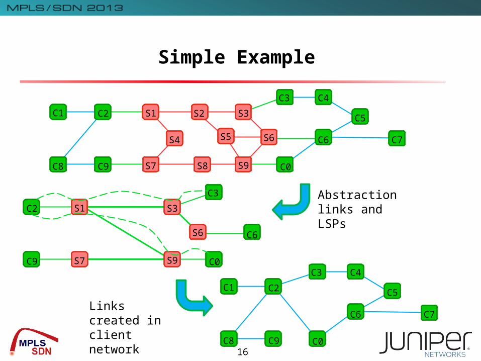
Simple Example
C1
C4
C0
C3
C9
C2
C8
S6 C7C6
C5
S5S4
S3S2S1
S9S8S7
C0
C3
C9
C2
S6 C6
S3S1
S9S7
C1
C4
C0
C3
C9
C2
C8
C7C6
C5
Abstraction links and LSPs
Links created in client network
16

17
Conclusion
• This is nothing radically new• It provides an over-all architecture that encompasses other models
• Easy to model the UNI as the interface between client and abstraction layer
• Extremes of full mesh aggregation can be accommodated with suitable policies
• Different technology layer relationships including lambda over lambda with stitching
• In simple networks realising the architecture may be overkill• The Abstraction Layer provides a powerful tool in more complex
networks• Interconnected (peer) server domains
• Alternative server domains (especially different technologies)
• This approach virtualises the network• Turns the network into a manageable service