wxes2106 network technology semester 1 2004/2005 chapter 3 ethernet ccna1: module 6, 7 and 8
Post on 21-Dec-2015
216 views
TRANSCRIPT
WXES2106Network Technology
Semester 1 2004/2005
Chapter 3
Ethernet
CCNA1: Module 6, 7 and 8
Contents
Introduction Ethernet Fundamentals Ethernet Operation Legacy Ethernet Fast Ethernet Gigabit Ethernet Ethernet Switching Collision Domains Broadcast Domains
Introduction
Ethernet is now the dominant LAN technology in the world
Ethernet specifications support different media, bandwidths, and other Layer 1 and 2 variations
The success of Ethernet is due to the following factors: Simplicity and ease of maintenance Ability to incorporate new technologies Reliability Low cost of installation and upgrade
Introduction
Ethernet is a family of networking technologies that includes Legacy, Fast Ethernet, and Gigabit Ethernet.
Ethernet speeds can be 10, 100, 1000, or 10,000 Mbps. IEEE standard for Ethernet is 802.3 Ethernet relies on baseband signaling, which uses the
entire bandwidth of the transmission medium. In 1980s, IEEE announced a standard for 10-Mbps. In 1995, IEEE announced a standard for a 100-Mbps. In 1998, IEEE announced a standard for a 1-Gbps

Introduction

Ethernet Fundamental
Ethernet operates in two areas of the OSI model, the lower half of the data link layer, known as the MAC sub layer and the physical layer
To move data between one Ethernet station and another, the data often passes through a repeater
Stations separated by repeaters are within the same collision domain. Stations separated by bridges or routers are in different collision domains.
Ethernet at Layer 1 involves interfacing with media, signals, bit streams that travel on the media, components that put signals on media, and various topologies.
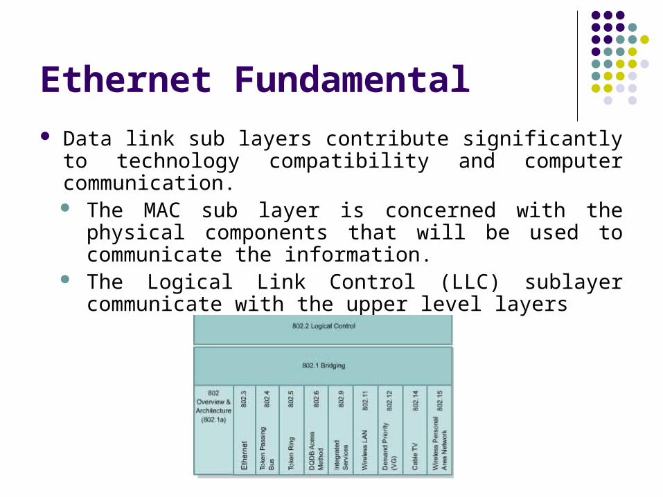
Ethernet Fundamental Data link sub layers contribute significantly to technology
compatibility and computer communication. The MAC sub layer is concerned with the physical
components that will be used to communicate the information.
The Logical Link Control (LLC) sublayer communicate with the upper level layers
Ethernet Fundamental
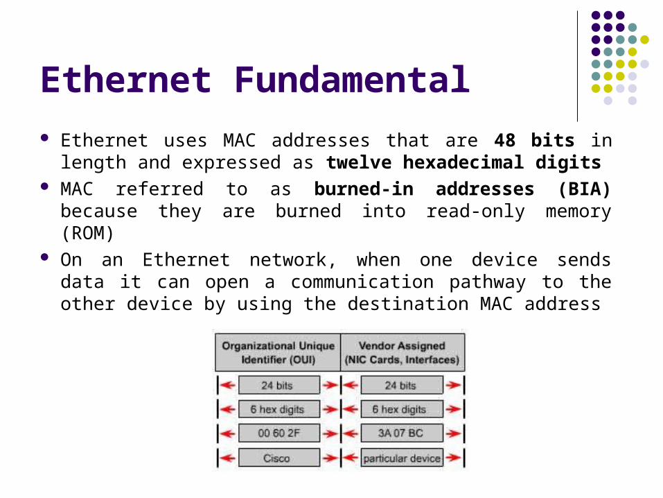
Ethernet uses MAC addresses that are 48 bits in length and expressed as twelve hexadecimal digits
MAC referred to as burned-in addresses (BIA) because they are burned into read-only memory (ROM)
On an Ethernet network, when one device sends data it can open a communication pathway to the other device by using the destination MAC address

Ethernet Fundamental
Source device attaches a header with destination MAC address. As this data propagates along the network media, the NIC in each device on the network checks to see if the MAC address matches the physical destination address carried by the data frame.
When the data reaches the destination node, the NIC makes a copy and passes the frame up the OSI layers.
On an Ethernet network, all nodes must examine the MAC header even if the communicating nodes are side by side.
Ethernet Fundamental
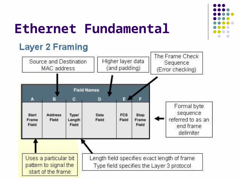
Framing is the Layer 2 encapsulation process. A frame is the Layer 2 protocol data unit. A single generic frame has sections called fields, and
each field is composed of bytes. The names of the fields are as follows: Start frame field Address field Length / type field Data field Frame check sequence field
Ethernet Fundamental

Ethernet Fundamental
The reason for sending frames is to get upper layer data, ultimately the user application data, from the source to the destination.
Data package has two parts, the user application data and the encapsulated bytes to be sent to the destination computer.
There are three primary ways to calculate the Frame Check Sequence number: Cyclic Redundancy Check (CRC) Two-dimensional parity Internet checksum

Ethernet Fundamental
IEEE 802.3 Ethernet
Ethernet Operation
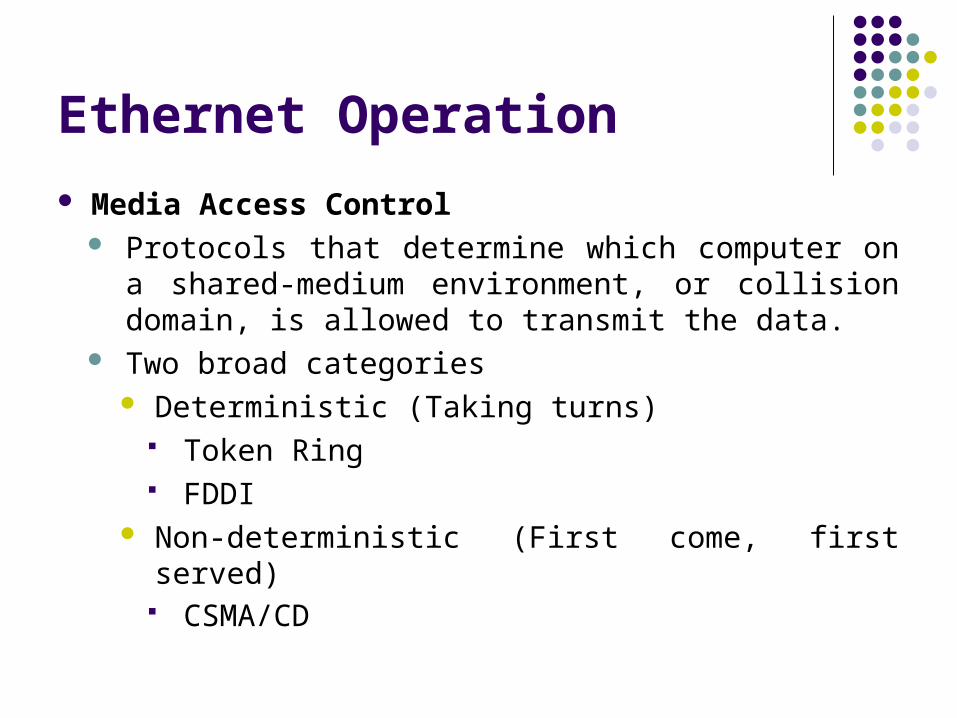
Media Access Control Protocols that determine which computer on a shared-
medium environment, or collision domain, is allowed to transmit the data.
Two broad categories Deterministic (Taking turns)
Token Ring FDDI
Non-deterministic (First come, first served) CSMA/CD

Ethernet Operation
Token Ring Individual hosts are arranged in a ring and a special
data token travels around the ring to each host in sequence.
When a host wants to transmit, it seizes the token, transmits the data for a limited time, and then forwards the token to the next host in the ring.
Token Ring is a collisionless environment as only one host is able to transmit at any given time.
Ethernet Operation
Fiber Distributed Data Interface (FDDI) Specifying a 100-Mbps token-passing network using
fiber-optic cable, with transmission distances of up to 2 km.
FDDI uses a dual-ring architecture to provide redundancy.
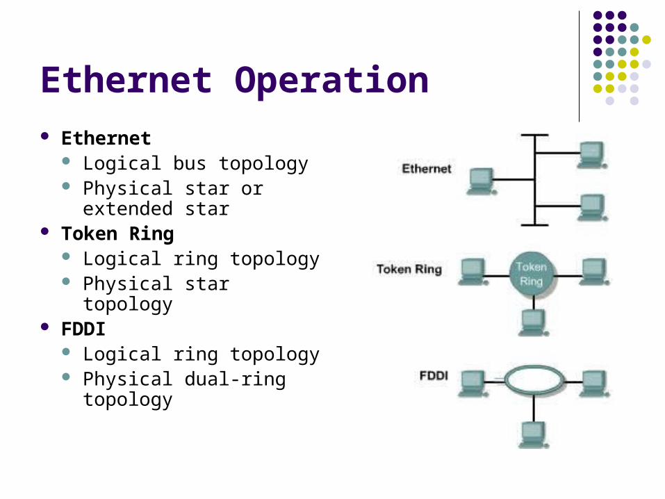
Ethernet Operation Ethernet
Logical bus topology Physical star or
extended star Token Ring
Logical ring topology Physical star topology
FDDI Logical ring topology Physical dual-ring
topology

Ethernet Operation Carrier Sense Multiple Access Collision Detection
(CSMA/CD) Three functions
Transmitting and receiving data packets Decoding data packets and checking them for valid
addresses before passing them to the upper layers of the OSI model
Detecting errors within data packets or on the network
Devices ready to transmit data first check the channel for a carrier. If no carrier is sensed for a specific period of time, a device can transmit.

Ethernet Operation If two devices transmit
at once, a collision occurs and is detected by all colliding devices.
This collision subsequently delays retransmissions from those devices for some random length of time
After completing data transmission the device will return to listening mode.
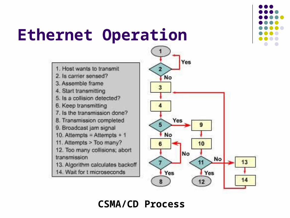
Ethernet Operation
CSMA/CD Process
Ethernet Operation Full Duplex
The station may send and receive simultaneously and collisions should not occur.
Changes the timing considerations and eliminates the concept of slot time.
Allows for larger network architecture designs Half Duplex
Sending station will transmit 64 bits of timing synchronization information that is known as the preamble.
It will then transmit the rest of the frame.
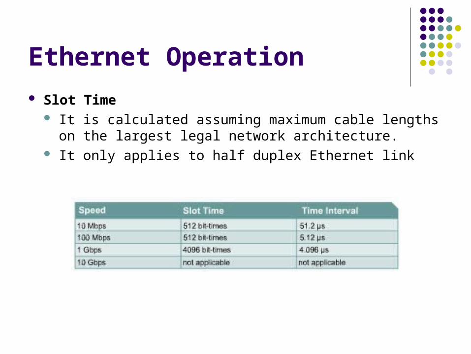
Ethernet Operation
Slot Time It is calculated assuming maximum cable lengths on
the largest legal network architecture. It only applies to half duplex Ethernet link

Ethernet Operation
Interframe Spacing The minimum spacing between two non-colliding
frames
Ethernet Operation The most common error condition on an Ethernet is the
collision. Collisions result in network bandwidth loss that is equal
to the initial transmission and the collision jam signal. A single collision is a collision that was detected while
trying to transmit a frame Multiple collisions indicate that the same frame collided
repeatedly before being successfully transmitted. Three types of collisions are:
Local Remote Late
Ethernet Operation Local Collision
A collision where a station detects a signal on the RX pair at the same time it is sending on the TX pair.
Remote Collision A collision where a frame that is less than the
minimum length, has an invalid FCS checksum Late Collision
A collision occurs after the first 64 octets of data has been transmitted by the sending stations.
Ethernet Operation Ethernet Error
Collision or runt Late collision Jabber, long frame and range errors Short frame, collision fragment or runt FCS error Alignment error Range error Ghost or jabber

Ethernet Operation
Auto-Negotiation automatically configures an interface to match the speed and capabilities of its link partner.
It defines how two link partners may automatically negotiate a configuration offering the best common
performance level.
Transmission Priority Rank

Legacy Ethernet 10BASE5, 10BASE2, and 10BASE-T Common features
Timing parameters Frame format Transmission process Basic design rule
Operates within the timing limits offered by a series of not more than five segments separated by no more than four repeaters.
No more than three populated segments between any two distant stations

Legacy Ethernet
Legacy Ethernet 10BASE5
Transmitted 10 Mbps Use thick coaxial cable, also known as thicknet Bus topology Uses Manchester encoding Half duplex only Maximum length 500 metres
Legacy Ethernet 10BASE2
Transmitted 10 Mbps Use thin coaxial cable, also known as thinnet Bus topology Uses Manchester encoding Half duplex only Maximum length 185 metres Easier to install
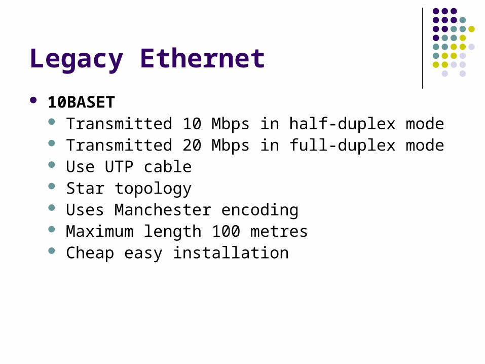
Legacy Ethernet 10BASET
Transmitted 10 Mbps in half-duplex mode Transmitted 20 Mbps in full-duplex mode Use UTP cable Star topology Uses Manchester encoding Maximum length 100 metres Cheap easy installation

Fast Ethernet
100BASE-TX, 100BASE-FX Common features
Timing parameters Frame format Parts of transmission process
Generally consist of a connection between a station and a hub or switch

Fast Ethernet

Fast Ethernet
100BASE-TX Carries 100 Mbps of traffic in half-duplex mode Carries 200 Mbps of traffic in full-duplex mode Use Cat 5 UTP cable Extended Star topology Uses 4B/5B encoding Unrepeated distance up to 100 metres Switches more commonly used than hubs

Fast Ethernet
100BASE-FX Carries 100 Mbps of traffic in half-duplex mode Carries 200 Mbps of traffic in full-duplex mode Uses multimode fiber optic cable Extended Star topology Uses 4B/5B encoding
Gigabit Ethernet
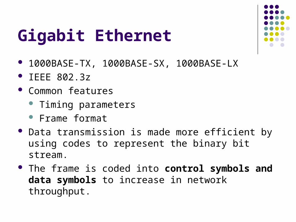
1000BASE-TX, 1000BASE-SX, 1000BASE-LX IEEE 802.3z Common features
Timing parameters Frame format
Data transmission is made more efficient by using codes to represent the binary bit stream.
The frame is coded into control symbols and data symbols to increase in network throughput.

Gigabit Ethernet

Gigabit Ethernet
1000BASE-T IEEE 802.3ab Uses CAT 5E Twisted pair cable Capable of full duplex operation on all four pairs to
create max speed of 1Gbps Uses 4D-PAM5 Encoding scheme Max 100 Meters distance Supports both half-duplex as well as full-duplex
operation
Gigabit Ethernet
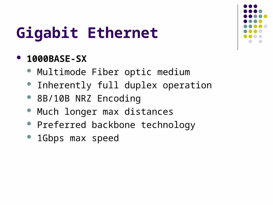
1000BASE-SX Multimode Fiber optic medium Inherently full duplex operation 8B/10B NRZ Encoding Much longer max distances Preferred backbone technology 1Gbps max speed
Gigabit Ethernet
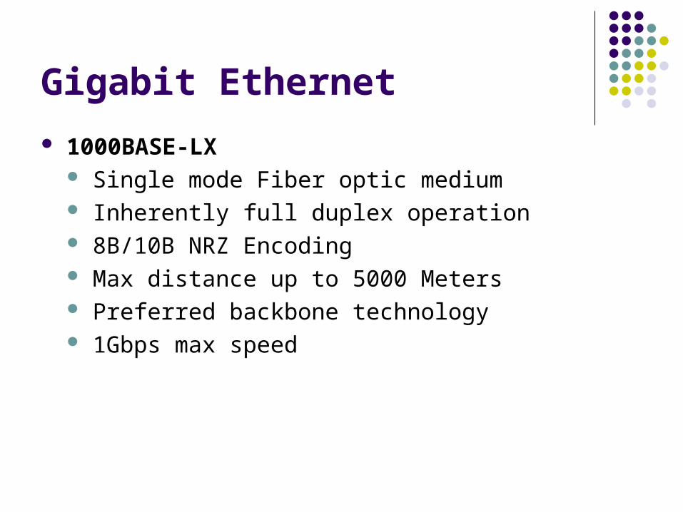
1000BASE-LX Single mode Fiber optic medium Inherently full duplex operation 8B/10B NRZ Encoding Max distance up to 5000 Meters Preferred backbone technology 1Gbps max speed

Gigabit Ethernet

Gigabit Ethernet
10-Gigabit Ethernet IEEE 802.3ae 10 Gbps Max speed Full duplex operation Fiber Optic cable Used for LAN’s MAN’s and WAN’s Max distances of up to 40km Single-mode fiber and compatibility with synchronous
optical network (SONET) and synchronous digital hierarchy (SDH) networks

Gigabit Ethernet 10GBASE-SR
Short distances multimode fiber Range between 26 m to 82 m
10GBASE-LX4 Uses wavelength division multiplexing (WDM) Single-mode fiber Supports 240 m to 300 m
10GBASE-LR and 10GBASE-ER Single-mode fiber Support 10 km and 40 km
10GBASE-SW, 10GBASE-LW, and 10GBASE-EW Work with OC-192 synchronous transport module (STM)
SONET/SDH WAN equipment

Ethernet Switching
Ethernet is a shared media, which means only one node can transmit data at a time.
The addition of more nodes increases the demands on the available bandwidth and places additional loads on the media.
Bridging was developed to help ease performance problems that arose from increased collisions.
Bridge keeps a table of MAC addresses and the associated ports. The bridge then forwards or discards frames based on the table entries.

Ethernet Switching

Ethernet Switching All decisions made by a bridge are based on MAC or
Layer 2 addressing and do not affect the logical or Layer 3 addressing.
A bridge will create more collision domains but will not add broadcast domains.

Ethernet Switching A switch is essentially a fast, multi-port bridge A switch dynamically builds and maintains a Content-
Addressable Memory (CAM) table, holding all of the necessary MAC information for each port
Using CAM allows a switch to directly find the port that is associated with a MAC address without using search algorithms.
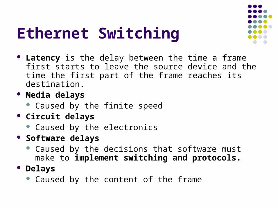
Ethernet Switching Latency is the delay between the time a frame first starts
to leave the source device and the time the first part of the frame reaches its destination.
Media delays Caused by the finite speed
Circuit delays Caused by the electronics
Software delays Caused by the decisions that software must make to
implement switching and protocols. Delays
Caused by the content of the frame
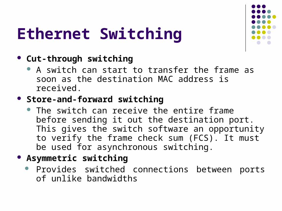
Ethernet Switching Cut-through switching
A switch can start to transfer the frame as soon as the destination MAC address is received.
Store-and-forward switching The switch can receive the entire frame before
sending it out the destination port. This gives the switch software an opportunity to verify the frame check sum (FCS). It must be used for asynchronous switching.
Asymmetric switching Provides switched connections between ports of
unlike bandwidths

Ethernet Switching
Spanning-Tree Protocol (STP) To resolve and shut down the redundant paths Switching loops can lead to broadcast storms that will
rapidly overwhelm a network. Each switch in a LAN using STP sends special
messages called Bridge Protocol Data Units (BPDUs) out all its ports to let other switches know of its existence and to elect a root bridge for the network.

Collisions Domain Collision domains are the connected physical network
segments where collisions can occur. Every time a collision happens on a network, all
transmission stops for a period of time. Adding layer 1 devices extend collision domains 5-4-3-2-1 rule
Five segments of network media Four repeaters or hubs Three host segments of the network Two link sections (no hosts) One large collision domain

Collisions Domain Layer 2 devices segment or divide collision domains. Segmentation makes networks more efficient and allow
data to be transmitted on different segments of the LAN at the same time without the frames colliding.
Layer 3 devices, like Layer 2 devices, do not forward collisions

Collisions Domain

Broadcast Domain To communicate with all collision domains, protocols use
broadcast and multicast frames at Layer 2 of the OSI model.
It sends a broadcast frame with a destination MAC address 0xFFFFFFFFFFFF
Layer 2 devices must flood all broadcast and multicast traffic
The three sources of broadcasts and multicasts in IP networks are workstations, routers, and multicast applications.
Broadcast storm The circulation of broadcast radiation that saturate the
network

Broadcast Domain Workstations broadcast an Address Resolution
Protocol (ARP) request every time they need to locate a MAC address that is not in the ARP table.
The routing protocols that are configured on a network can increase broadcast traffic significantly.
Every 30 seconds, RIPv1 uses broadcasts to retransmit the entire RIP routing table to other RIP routers.
A broadcast domain is a grouping of collision domains that are connected by Layer 2 devices.
Broadcasts have to be controlled at Layer 3 because routers do not forward broadcasts.

Broadcast Domain Any segments connected by Layer 1 devices are part of the
same domain, both collision and broadcast. A Layer 2 device creates multiple collision domains but
maintains only one broadcast domain. A Layer 3 device creates multiple collision and broadcast
domains. Network Segment
Section of a network that is bounded by bridges, routers, or switches.
In a LAN, a segment often connected to other segments with repeaters
In TCP, it is used to describe a single transport layer unit of information.

Broadcast Domain