wyle report - rdu aircraft noise report wr 03-10 new construction acoustical design guide prepared...
TRANSCRIPT

Wyle Report
WR 03-10
NEW CONSTRUCTION ACOUSTICAL DESIGN GUIDE
Prepared For
CITY OF HIGH POINT 211 S. Hamilton Street High Point, NC 27261
Prepared By
Clint Morrow Gary Ehrlich William Albee
Wyle Acoustics Group
WYLE LABORATORIES 2001 Jefferson Davis Highway
Suite 701 Arlington, Virginia 22202
(J/N 47764)
March 2003

WR 03-10 New Construction Acoustical Design Guide March 2003
1-1
Table of Contents
1.0 Introduction.................................................................................................. 1-1
1.1 Background........................................................................................................1-1 1.2 How to Use This Guide ........................................................................................1-1 2.0 Noise Control Basics ...................................................................................... 2-1
2.1 Units Used in Acoustics........................................................................................2-1 2.2 Aircraft Noise .....................................................................................................2-3 2.3 Sound Insulation to Reduce Noise.........................................................................2-4 2.4 Basic Sound Insulation Concepts ..........................................................................2-5 3.0 Building Elements.......................................................................................... 3-1
3.1 Evaluating Construction Materials and Methods ......................................................3-1 3.2 Sealing and Weatherstripping...............................................................................3-2 3.3 Windows ............................................................................................................3-2 3.4 Doors ............................................................................................................3-4 3.5 Walls and Ceilings...............................................................................................3-7 3.6 Attics and Roofs ............................................................................................... 3-10 3.7 Floors, Basements, and Crawl Spaces.................................................................. 3-12 3.8 Ventilation ...................................................................................................... 3-13 3.9 Miscellaneous................................................................................................... 3-15 4.0 Material Selection Chart ................................................................................. 4-1
5.0 Limitations ................................................................................................... 5-1
Appendices Text Formatting..................................................................................... A-1
Appendix A Noise Level Reduction Design Requirements ..............................................A-1 Appendix B Manufacturers of Acoustical Materials .......................................................B-1 Appendix C Independent Certified Acoustical Testing Laboratories.................................C-1 Appendix D Glossary............................................................................................... D-1

WR 03-10 New Construction Acoustical Design Guide March 2003
1-2
List of Figures Figure No.
2-1 Pictorial Representation of Sound Transmission Through Built Construction .......................2-5 2-2 Sound Transmission Paths Into Dwelling Interiors ..........................................................2-6 3-1 Typical Aluminum Dual Window Detail ..........................................................................3-3 3-2 Construction Features of Acoustical Window ..................................................................3-3 3-3 Sliding Glass Door Detail .............................................................................................3-6 3-4 Staggered Wood Stud Construction ..............................................................................3-8 3-5 Built-in-Place Gable Baffle ......................................................................................... 3-11 3-6 Controlling Noise Entering Through Ducts in Attic Space................................................ 3-14
List of Tables Table No.
2-1 Typical STC Ratings for Common Construction Elements .................................................2-8 3-1 Acoustical Wall Designs and STC Ratings.......................................................................3-9 3-2 Material Thickness and R-Value for Common Insulating Materials ................................... 3-12

WR 03-10 New Construction Acoustical Design Guide March 2003
1-1
1.0 Introduction
1.1 Background
Residences located near airports experience many economic and transportation benefits of the facility, but are unfortunately exposed to significant amounts of aircraft noise. However, using proper construction techniques and materials minimizes the impact of aircraft noise and reduces interference with regular indoor activities. The High Point International Airport has developed this New Construction Acoustical Design Guide to assist builders, planning officials, building inspectors, and homeowners in incorporating specific noise level reduction features into the designs of new homes. These features will help to ensure that new homes in the Airport vicinity provide an adequate noise level reduction to protect occupants from undesirable noise impacts.
For homes located in areas with high noise levels, standard building methods, even those that are designed for thermal efficiency, are normally inadequate to protect inhabitants from external noise. For this reason, building design and construction methods may have to be modified for noise-sensitive rooms such as bedrooms, living rooms, and family rooms. These spaces are referred to as the habitable rooms in a house. Standard design and construction methods can typically be used for non-habitable rooms, such as garages, mudrooms, and breezeways unless they open directly to habitable rooms without interior doors in between the rooms.
This Design Guide provides recommendations for the design of dwellings in the vicinity of the airport that may be constructed in the future. It is meant to be used in conjunction with a noise overlay zone that Wyle Laboratories has developed for the Planning and Development Department of the City of High Point. This Guide was developed for new homes; different materials and techniques would be appropriate when renovating houses to achieve the noise level reduction goals. Construction guidelines are presented for the noise level reductions (NLRs) of 25, 30, and 35 decibels.
1.2 How to Use this Guide
This guide has been developed to be used by a variety of different professionals, as well as by interested homeowners. This guide is recommended for the following people:
• Planning Officials
• Plan Reviewers
• Building Inspectors
• Builders
• Homebuyers/Homeowners

WR 03-10 New Construction Acoustical Design Guide March 2003
1-2
Sections 2.0 Through 3.0
The main design guide sections include a brief overview of sound transmission paths into a home, a discussion of basic design principles, and subsections for each building element including walls, windows, doors, ceilings, attics, floors, basements, crawlspaces, and ventilation systems. The building element subsections include text, tables, and design detail drawings to illustrate various options for noise control.
Section 4.0
Specific design modifications are presented in a selection chart. Designs that achieve noise level reductions (NLR) of 25, 30 and 35 dB are listed. The table in Section 4.0 tells the sound ratings of building materials that are needed to achieve the NLR design goals.
Section 5.0
This section discusses some of the assumptions used in developing the proposed design methods, as well as factors that would affect the accuracy of NLR predictions.
Appendix
The first appendix provides a summary of design and construction methods necessary to achieve NLRs of 25, 30, and 35 dB. Once the reader is familiar with this Guide, Appendix A can be used as a stand-alone reference in implementing the designs. Appendices B and C will be useful to builders, as they provide information on many acoustical product manufacturers and certified test laboratories. Appendix D is a glossary that will be useful to all parties.
This Guide seeks to provide clear, unambiguous direction that is practical and can be implemented with minimum additional cost. However, construction quality is especially important for maintaining the acoustical integrity of a design. For example, even a good window, if not installed properly, will allow a significant amount of noise into the building. High-quality construction standards are absolutely essential for these techniques to work effectively.
The design packages in Section 4.0 and Appendix A address typical home sizes and styles. The noise analysis used here makes assumptions about the number of exterior doors and the size of the windows with respect to the floor area. Unusual homes may require more specialized analysis to ensure compliance. For example, very small rooms with normal windows have a larger window-to-floor space ratio and may allow more noise intrusion than average sized rooms. Similarly, rooms with very large windows or a room with several windows and exterior doors may also allow more noise to enter. Unusually large windows would require better acoustical performance than is indicated in this report in order to meet the noise level reduction goals. The use of cathedral ceilings is strongly discouraged for homes exposed to aircraft noise because the attic normally acts as a noise buffer. Conversely, homes with large wrap-around porches may provide shielding from noise that the Guide will not anticipate. For these reasons, homes with unique features or with

WR 03-10 New Construction Acoustical Design Guide March 2003
1-3
dimensions that differ significantly from the average may require the services of an acoustics consultant or acoustics-knowledgeable architect in order to ensure adequate noise reduction.
Individuals differ in their response to noise. In an aircraft noise-affected neighborhood, a number of residents are very annoyed by aircraft overflights, while quite a few others are not. If properly implemented, the recommendations in this Guide will reduce noise inside the home to levels that most people will find acceptable. The airplanes will still be discernible; sound insulation is not sound elimination. People will know that a plane is passing overhead but, with the techniques outlined in this Guide, the noise should not be so loud that it interferes with normal daily indoor activities. Those individuals, however, who are most sensitive to noise, may continue to be annoyed. Nevertheless, the number of people who perceive unacceptable indoor noise levels can be significantly reduced by the use of proper construction techniques.

WR 03-10 New Construction Acoustical Design Guide March 2003
2-1
2.0 Noise Control Basics
2.1 Units Used in Acoustics
A number of different metrics (measures) have been developed to express various aspects of acoustics. It is important to understand several of them in order to make the best use of this Guide.
Aircraft noise is generally expressed in terms of its A-weighted sound level, in units called “decibels.” Strictly speaking, the decibel unit should be abbreviated only by "dB"; however, for clarity "dBA" and "dB(A)" are often used to highlight the fact that the sound level measurement has been A-weighted (this weighting system is described below).
The noise exposure in areas around airports is expressed in terms of the Day-Night Average Sound Level, which is abbreviated by "DNL" in text and "Ldn" in equations. DNL is a measure of the average A-weighted sound level of all aircraft flights occurring in a 24-hour period with nighttime operations being counted more heavily as described below. The unit of DNL is also the decibel.
The sound insulation properties of building construction materials are described by Sound Transmission Loss (TL) or Sound Transmission Class (STC). These measures of sound insulation are also described below.
A-Weighted Sound Level
The two most obvious characteristics of sound are level and frequency. Level is essentially a measure of loudness that refers to how much energy or power a sound has when we hear it. Frequency is essentially a measure of pitch. A deep-voiced baritone singer has a lower frequency (or pitch) than a soprano voice, though they may be equally loud. Hertz (abbreviated Hz) is the unit used to indicate frequency and is equal to the number of sound waves (cycles) per second. For reference, middle C on a piano has a frequency of exactly 256 Hz. The normal human ear can detect sound frequencies ranging from about 20 Hz to about 15,000 Hz. People do not hear all sounds over this wide range of frequencies equally well, however. The human ear is most sensitive to sounds in the 1000 to 6000 Hz range.
In order to reflect the differences in hearing sensitivity to different frequencies, sounds are usually described in terms of A-weighted sound levels. When a sound is A-weighted, sound levels measured in the 1000 to 6000 Hz frequency range are increased by a specified amount to account for the fact that the ear perceives them as louder compared to other frequencies. Similarly, sound levels measured at frequencies outside this range are reduced because the ear is less sensitive in those regions.

WR 03-10 New Construction Acoustical Design Guide March 2003
2-2
Day-Night Average Sound Level (DNL) and Noise Contours
Aircraft noise exposure in a community is usually described in terms of noise contour maps. These indicate bands or zones around airfields where the average noise level can be expected to fall within the ranges specified by the contour lines. The Federal Aviation Administration (FAA) states that areas with a noise exposure of DNL 65 dB and higher are ”significantly” impacted by noise. Most noise contour maps show contour levels of DNL 65 dB and above in 5 dB increments.
The acoustic metric used is the Day-Night Average Sound Level (DNL or Ldn ). This is a cumulative measure of the noise exposure during a 24-hour calendar day. A 10 dB penalty is added to noise events occurring between 10:00 p.m. and 7:00 a.m. to reflect their greater intrusiveness and potential for disturbing sleep. The DNL is the result of averaging the A-weighted sound pressure level over 24 hours for aircraft activities taking place on an average day. The average day is determined by analyzing flight activity over the period of one full year. This gives an indication of the year-round average noise exposure for the community.
Sound Transmission Loss (TL)1
This is the physical measure which describes the sound insulation value of a building element such as a window or wall. Values of TL are determined in acoustical laboratories under controlled testing methods prescribed by the American Society for Testing and Materials (ASTM). The TL is expressed in decibels (dB), and the greater the sound insulation, the higher the TL value and the less sound will be transmitted through the building material. TL values are determined for different frequency ranges and give an indication of how a building product responds differently to sounds at different frequencies.
Sound Transmission Class (STC)2
Since working with a series of TL measurements for different frequencies can be cumbersome, a single-number descriptor based on the TL values has been developed. This rating method is called the Sound Transmission Class (STC). As with the TL, the greater the STC rating for a construction method or component, the higher the sound insulation. Originally, STC ratings were developed as a single-number descriptor for the TL of interior office or apartment walls for typical office noise and speech spectra. Now, they are used for exterior building components as well. Most acoustical materials and components are commonly specified in terms of their STC ratings.
1 Typical tests to determine TL are described in American Society of Testing and Materials (ASTM)
Standard E90. 2 STC is described in ASTM Standard E413.

WR 03-10 New Construction Acoustical Design Guide March 2003
2-3
2.2 Aircraft Noise
Interference With Activities
The problem of aircraft noise has been recognized and studied in this country since the 1950s. Opinion surveys indicate that interference with telephone usage, listening to television and radio, and conversation invoke the most complaints. However, after a home has been sound insulated, residents notice improvements in their ability to carry out these normal activities as well as to fall asleep and concentrate.
Fears of permanent hearing damage from flyovers have been shown to be unfounded. A large number of studies on the physical, mental, and emotional health effects of aircraft noise exposure have led to the general conclusion that residences near airports are not exposed to high enough sound levels to warrant concern. The principal effect of aircraft noise on airfield neighbors is annoyance, caused by interference with daily activities.
Aircraft Noise Characteristics
Noise intrusion from aircraft activities is perceived as more disturbing than other kinds of noise because of two primary characteristics. Unlike many other community noise sources, such as highway noise, which tend to be fairly constant, aircraft noise consists of sporadic individual noise events with a distinct rise and fall pattern. People do not, in general, respond to these events as just another component of the "background noise" of their day-to-day lives. Some people get used to the noise, but many others feel that each individual flyover event is recognizable and disturbing.
The noise level experienced at a particular dwelling will depend on its location relative to the aircraft flight paths and the mode of ongoing aircraft operations (arrivals or departures). For homes very near the airport, the second quality that makes aircraft noise more intrusive is its higher level, or loudness, than other types of community noise.
Aircraft Sound Spectrum
The noise produced by modern aircraft contains acoustical energy over a wide frequency range. The audible noise includes many sounds from a low-frequency "rumble" to a high-frequency "whine." The exact character depends on the aircraft type and the operation performed (takeoff, landing, or ground run-up). Low-frequency noise (below 500 Hz) penetrates walls, roofs, doors, and windows much more efficiently than does high-frequency noise. Higher frequencies (above 1000 Hz), however, are carried through cracks and vents better. Also, people hear higher frequency sound better, the human ear being more sensi-tive above 1000 Hz than below.
Since aircraft noise differs somewhat from other types of community noise, it is important to identify the characteristics of the noise that sound insulation is protecting against. Most materials and construction methods are more effective at insulating in one part of the frequency spectrum than in others. Knowing the noise characteristics helps in choosing the best materials for sound insulation. This Guide has been designed specifically to protect against aircraft noise rather than highway noise or some other problem.
Most of the sound energy from aircraft operations is found at lower frequencies. While this energy is below the most sensitive region of people's hearing range, it can be heard well

WR 03-10 New Construction Acoustical Design Guide March 2003
2-4
enough to be annoying and it can cause disturbing structural vibration in a dwelling. Section 2.4 discusses the process by which sound is transmitted into a dwelling interior.
2.3 Sound Insulation to Reduce Noise
Total "soundproofing" of the dwelling, such that aircraft operations are not heard, is usually not practical or cost-effective. The goal for residential sound insulation is to reduce the dwelling interior noise levels due to aircraft operations to an acceptable level, that is, a level where it no longer interferes with daily activities.
Interior Noise Objectives
The Federal Aviation Administration (FAA) has established guidelines for the noise level reduction that a home must provide in order to be comfortable in the presence of aircraft noise. The FAA land-use compatibility table recommends that a home exposed to a DNL of 65 to 70 dB should provide at least 25 dB of NLR, and a home exposed to a DNL of 70 to 75 dB should provide at least 30 dB of NLR. The use of other NLR goals may be appropriate in many cases, especially if a noise metric other than DNL is used at that airport.
Room Variations
The noise level of different rooms in a house depends on the absorption within the room, as well as on the noise entering from outside. Upholstered furniture, drapes, and carpeting absorb sound while hard surfaces do not. The exterior sound level is transmitted through the outside walls (depending on their construction) and is further modified by the absorption inside the room (from the various furnishings) to determine what the interior noise level will be.
Expected Dwelling Noise Level Reduction
An acoustically well-insulated home with windows and doors kept closed can provide 30 to 35 dB of NLR whereas more typical, unmodified designs might provide 20 to 25 dB of NLR. Experience has proven that the objectives discussed here are reasonable when construction materials and methods follow the guidelines presented in Sections 3.0 and 4.0. Providing more than 40 dB of noise level reduction is not usually practical for a typical residence. Of course, sound insulation will not have any effect on outdoor activities. The advantage of sound insulation is that it provides a refuge from external aircraft noise levels.
In general, it is more efficient and cost effective to take acoustic performance into account at the start when designing and building a home. Remodeling a pre-existing home is far more costly and time consuming than anticipating and building using good sound insulation techniques. This Guide was developed for new homes; different materials and techniques would be appropriate when renovating houses to achieve the NLR goals.

WR 03-10 New Construction Acoustical Design Guide March 2003
2-5
2.4 Basic Sound Insulation Concepts
Sound Transmission
In order to effectively examine noise control measures for dwellings it is helpful to understand how sound travels from the exterior to the interior of the house. This happens in one of two basic ways: through the solid structural elements and directly through the air. Figure 2-1 illustrates the sound transmission through a wall constructed with a brick exterior, stud framing, interior finish wall, and absorbent material in the cavity.
Figure 2-1. Pictorial Representation of Sound Transmission Through Built Construction
The sound transmission starts with noise at the wall exterior. Some of this sound energy will be reflected away and some will make the wall vibrate. The vibrating wall radiates sound into the airspace, which in turn sets the interior finish surface vibrating, with some energy lost in the airspace. This finish surface then radiates sound into the dwelling interior. As the figure shows, some vibrational energy also bypasses the air cavity by traveling through the studs and edge connections.
Openings in the dwelling, which provide air infiltration paths through windows, vents, and leaks, allow sound to travel directly into the interior. This is a very common, and often overlooked, source of noise intrusion. Basically, any way that air enters a home, sound will also enter.

WR 03-10 New Construction Acoustical Design Guide March 2003
2-6
Flanking is a similar concept and usually refers to sound passing around a wall. Examples of common flanking paths include: air ducts, open ceiling or attic plenums, continuous side walls and floors, joist and crawlspaces.
Figure 2-2 displays the three different major paths for noise transmission into a dwelling: air infiltration through gaps and cracks, secondary elements such as windows and doors, and primary building elements such as walls and the roof.
Figure 2-2. Sound Transmission Paths Into Dwelling Interiors
Low-frequency sound is most efficiently transmitted through solid structural elements such as walls, roofs, doors, and windows. High frequencies travel best through the air gaps.
Within these broad categories, different building materials have different responses based on the frequency of the incident sound and varying abilities to insulate against sound.
Reducing Transmitted Sound
The amount of sound energy transmitted through a wall, roof, or floor can be limited in several ways. First, all air infiltration gaps, openings, and possible flanking paths must be eliminated wherever possible. This is the single most important, but occasionally overlooked, step in noise level reduction. This includes keeping windows and doors closed and putting baffles on open-air vents. Some materials reflect more of the incident sound,

WR 03-10 New Construction Acoustical Design Guide March 2003
2-7
converting less of it into vibrational energy. The mass of the exterior and interior panels influences how much sound will pass through them. The more mass a structural element has the more energy it takes to set it into vibration, so using heavier building elements generally blocks more noise. Then, absorption in the air cavity, resilient mounting of interior finish panels, and mounting the exterior and interior panels on different studs can further reduce the sound transmitted to the room. The primary approaches for improving sound isolation are:
1. Elimination of openings and flanking paths.
2. Using higher STC windows and doors.
3. Adding mass to walls or ceilings.
4. Isolation of panel elements through increasing their separation, mounting the interior and exterior panels on different studs, or resiliently mounting the interior panels.
5. Adding absorptive materials between the studs or joists.
Acoustical Design
The most important, or controlling, sound paths must be identified in order to know how to modify a dwelling design to meet a specified noise criterion. The ideal sound insulation design would focus on those elements that transmit the most acoustical energy into a room. This eliminates any weak links in the building's insulation envelope.
Windows generally allow more noise intrusion than walls; as more of the wall area is taken up with windows, the overall noise protection decreases. This effect is significant even for massive wall materials, such as brick. Intuition suggests that a brick wall would protect better against sound than siding and this is true when these materials alone are compared. But, putting a weak window or an especially large window into a brick wall will cause the overall construction to perform very poorly since noise enters through the weakest path. On the other hand, installing a high-STC window in a siding wall will give much better noise level reduction than building a weak window into a brick wall.
The STC rating, defined in Section 2.1, is a measure of the material's ability to insulate against sound; the higher the STC rating, the better the insulator. Proper use of STC ratings will be discussed in more detail in Section 3.1. Table 2-1 gives a brief list of typical STC ratings for common building elements. Much of the variability for walls and roofs is due to the type of interior finish, the type of studs or joists, and whether there is insulation in the stud or joist cavities. The ratings in Table 2-1 cannot be used directly to estimate noise level reduction because they do not account for the presence of other elements or the areas of each element.
In most cases, after making sure that openings remain sealed, the windows are the controlling sound path. Using acoustical windows typically does more to improve the sound insulation performance than any other design modifications. Exterior doors typically require higher STC ratings. Depending on the NLR goal, other elements may become important in meeting specific noise level reduction goals. In some cases, ceilings and exterior walls may require special construction as well, particularly in the higher DNL noise zones. Treatments for these paths and others are discussed in Sections 3.2 through 3.9 of this Guide.

WR 03-10 New Construction Acoustical Design Guide March 2003
2-8
Table 2-1. Typical STC Ratings for Common Construction Elements
LARGE ELEMENTS
EXTERIOR WALLS STC (dB)1
Aluminum or Wood Siding 34-39 Stucco App. 46 Brick 54-56 ROOFS
Vented Attic App. 45 FLOORS
Slab Over 60 Vented Crawlspace App. 48 Basement App. 48
SMALL ELEMENTS WINDOWS2
Double-Strength Glazing 24-29
DOORS2
Hollow Core (HC) wood App. 20 Solid Core (SC) wood 23-29 Steel or fiberglass 22-28 Sliding Glass 25-29 1 A higher STC value indicates greater sound insulation.
2 Good weatherstripping condition.
Problem Areas
Sound intrusion problems are commonly caused by:
1. Building construction components and configurations not providing sufficient sound insulation.
2. Building elements, such as windows, doors, walls, roofs, and floors chosen and combined in an unbalanced way so that some parts are much weaker sound insulators than others.
3. Unintended openings or sound-flanking paths caused by improper installation of construction elements.
Thermal Insulation
While homes which are well insulated thermally often perform well acoustically, thermal insulation is not always a good indicator of sound insulation. Many thermal windows provide little sound insulation when compared to walls or acoustical windows and are frequently the weak link in the building envelope. However, thermal treatments usually

WR 03-10 New Construction Acoustical Design Guide March 2003
2-9
eliminate air infiltration and may serve to improve the acoustical performance of a dwelling for that reason. The presence of insulation in walls or ceilings is far more important than the type of the insulation.
Shielding
The last concept to consider is shielding. This refers to the fact that the side of the dwelling which faces away from the flight path and does not have an open line-of-sight to it will be protected somewhat from the noise. The shielding may be as much as 10 dB in some cases, though values on the order of 5 dB are more common. Sides of the house facing directly toward the flight path are unshielded. Sides which face the flight track at an angle may benefit from some minor shielding effects. Sometimes, however, sound is reflected off nearby buildings in such a way as to counteract the shielding benefits. Shielding must be examined on a case-by-case basis and the possibility of aircraft straying from the usual flight path must be taken into account before assuming a consistent shielding effect.
In general, a new dwelling should be oriented on the lot so that bedrooms and TV-viewing rooms face away from the flight track. This will eliminate the need to add extra sound insulation components to protect these noise-sensitive living areas.

WR 03-10 New Construction Acoustical Design Guide March 2003
3-1
3.0 Building Elements
This section provides specific guidelines for modifying standard construction designs and practices to meet the need for aircraft sound insulation in new homes. A general discussion of construction materials and methods is given in Section 3.1. Sections 3.2 through 3.9 address techniques for use with weatherstripping, windows, doors, walls and ceilings, attics, floors, HVAC systems, and other miscellaneous elements.
3.1 Evaluating Construction Materials and Methods
Informed Use of STC Ratings
STC ratings are the most common measures of acoustical performance given by manufacturers of building materials. For this reason, it is important to understand how to use STC ratings to evaluate construction materials and systems.
Two different construction methods or components may have identical STC ratings and yet may block aircraft noise differently because or their response at different frequencies. One method or component may perform better than another at some important frequencies. Selecting a construction method or component from a group only on the basis of the highest STC rating may not provide the intended sound insulation. This is because the STC rating does not take into account the strong low-frequency nature of aircraft noise. This guide has taken the ability of typical products to block aircraft noise into account. The recommended materials listed in Section 4.0 (and their STC ratings) were evaluated for frequency response prior to formulating the design packages.
Combining Building Elements
As mentioned earlier, the acoustical performance of the building depends on the combined performances of each of the elements. The final result depends on the transmission loss (or STC) and the relative surface areas of the elements. If any of the components has poor insulation properties the overall performance can be seriously weakened. This is why it is important to focus on the weaker elements and to consider the relative areas of the components.
As a rule-of-thumb, if a weaker element will be included in the assembly, its size should be kept to a minimum. For example, if a pane of glass is to be used for a vision panel in a door, it should be kept small and should be constructed of insulated glazing. Similarly, very large windows degrade the noise level reduction of an otherwise effective brick wall. If a cathedral ceiling is included, it should be designed so that there is a larger-than-standard air space between the ceiling and the roofing system, and this space must be insulated. In addition, slightly higher STC ratings should be used for windows and doors than indicated in Section 4.0. Sensible compromises can be made to preserve the noise level reduction of the home without sacrificing aesthetics, provided the principles explained in this Guide are employed.

WR 03-10 New Construction Acoustical Design Guide March 2003
3-2
3.2 Sealing and Weatherstripping
Good weatherstripping and caulking around windows and doors is crucial to effective sound insulation. The STC rating of the overall assembly can vary by as much as 2 to 4 dB, depending on perimeter infiltration. For these assemblies, any perimeter leakage will degrade the performance of the window or door and can be the controlling factor in the noise isolation. This is generally not an issue with new construction, but homeowners must understand the importance of maintaining weatherstripping in good condition.
For acoustical purposes, compressible neoprene weatherstripping is preferred over felt or other fibrous types. Neoprene is not as porous and compresses better against the window or door frame. Also, felt and fibrous weatherstripping materials tend to deteriorate more quickly than neoprene and must be replaced more often.
3.3 Windows
Options Overview
The exterior windows are usually one of the weakest elements in the dwelling's sound insulation performance. Improving the acoustical properties of the windows is one of the simplest ways of lowering the overall sound transmission into the house. Design modification options include using thicker glass and wider airspaces between the panes of glass. Specialized acoustical windows provide maximum sound insulation, and should be used in the loudest environments, as specified in Section 4.0.
Acoustical Performance
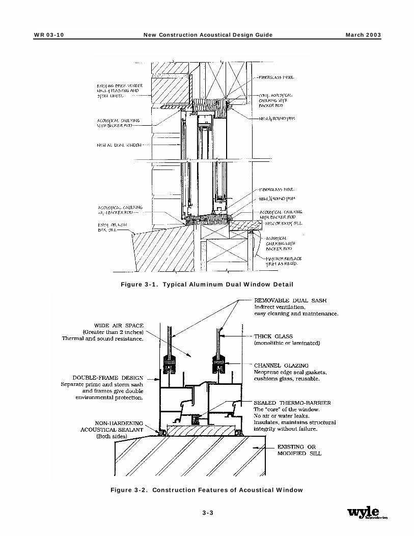
The thicker, high-quality insulated glass units should be ¾ inch to 1 inch thick and, for the best noise level reduction, should incorporate at least one lite (pane) of laminated glass, preferably ¼ inch thick. Laminated glass provides significantly better transmission loss than standard, float glass. Tempered glass is also acoustically superior to standard glass, but is not nearly as effective as laminated glass. Off-the-shelf thermopane units are typically available with ratings ranging from STC 24 to 29, and upgraded acoustical units with thicker glass may provide ratings as high as STC 30 to 36. Figure 3-1 shows a typical window installation with the most important features highlighted.
Acoustical windows differ significantly from ordinary residential windows. The design of an acoustical window has a greater frame depth, the glass lites are heavier, and the weatherstripping and seals are more substantial. Most importantly, they have additional lites. The two most common types of acoustical windows are a double pane window with a storm unit attached, or an assembly of two double pane windows connected together. All of these measures are necessary to provide the high degree of sound insulation required for the window assembly. Figure 3-2 shows schematically the features of an acoustical window. Proprietary windows with STC ratings of 39 to 48 are available in a variety of styles and finishes, including aluminum and vinyl. Information on specialized acoustical windows is available in Appendix A. They are considerably more expensive than typical residential windows.
WR 03-10 New Construction Acoustical Design Guide March 2003
3-3
Figure 3-1. Typical Aluminum Dual Window Detail
Figure 3-2. Construction Features of Acoustical Window

WR 03-10 New Construction Acoustical Design Guide March 2003
3-4
Thermal Performance
Insulated glass windows are recognized to block the transmission of heat (in winter or summer) much more effectively than single pane glazing. Increasing the thickness of the glass and the airspace, as recommended for noise level reduction, further improves their thermal performance.
Because of the above-mentioned design features, plus the common inclusion of thermal barriers at the frames, acoustical windows perform exceptionally well as thermal barriers. They allow approximately one-tenth the air infiltration of a typical 20-year-old double-hung wood window with single pane glass. The R-value (a measure of thermal resistance) for acoustical windows is R-4. For comparison, the R-values of most off-the-shelf single pane and double pane windows are R-1 and R-3, respectively.
Installation Considerations
For the windows to provide the required noise reduction they must remain tightly closed. Ways to maintain ventilation will be discussed in Section 3.8. It is important to note, however, that this requirement precludes the use of jalousie or louvered windows in a sound insulation design. Double-hung, single-hung, horizontal sliding, casement, fixed, and awning/hopper windows are all acceptable for noise reduction, provided they have the required STC rating.
Other considerations when preparing window specifications include maintainability, warranty, manufacturer's service, and proper installation. It is possible to install the best acoustical window improperly. If it does not fit tightly enough, air infiltration will significantly reduce the effectiveness. Starting with a too-small window unit and filling in the void around the window with a low-mass material such as fiberglass is unacceptable. Continuous wood blocking infill is, however, acceptable.
3.4 Doors
Options Overview
Doors are comparable to windows in the amount of sound they allow to enter the dwelling. Many typical residential doors require modification or substitution to provide the necessary protection from aircraft noise. As with windows, there are specialized acoustical units available, as well as acoustical storm doors. The following factors are important in evaluating doors for sound insulation:
• Door composition: hollow core wood, solid core wood, insulated metal or fiberglass, sliding glass; core material, additional internal insulation, etc.
• Door weight (can be estimated by pull-weight).
• Presence and type of fixed window panels.
• Quality of seals and weatherstripping and how tightly they seal.

WR 03-10 New Construction Acoustical Design Guide March 2003
3-5
The options for improving the noise level reduction of residential doors include:
• Installation of a tightly fitting storm door with thick (or laminated) glass; or use of a specialty acoustical storm door.
• Installation of a secondary French door.
• Use of thicker glass in sliding glass doors or specialty acoustical sliding glass doors.
Standard Doors
Standard entrance doors can be expected to have ratings of STC 21 to 27. STC requirements are outlined in Section 4.0 for each type of door (swinging and sliding doors).
Glass panels in the primary door can reduce the sound insulation by 3 to 5 dB, depending on the thickness of the lite and the surface area. The thinner the glass and the larger the area it covers, the more it decreases the sound insulation of the door. When vision panels are required, it is best to keep them small and use insulated glass units with thick glass.
Swinging Storm Doors
External storm doors are common in many parts of the country and can improve the STC rating by 3 to 10 dB. In order for storm doors to be effective for sound insulation, they should incorporate thick glass (ideally 1/4-inch-thick laminated glass) and have a heavy core. Storm doors must be mounted year-round. Replacing the glass panel with a screen insert in the summer months will reduce the sound insulation of the home considerably but many homeowners may wish to exercise this option for periods when aircraft activity is light. A list of acoustical storm door suppliers is included in Appendix B.
Acoustical Swinging Doors
Acoustical doors, with a typical rating of STC 30 to 40, are similar in appearance to standard entrance doors. However, due to the high cost of acoustical doors, it is often preferable instead to use more typical residential doors with acoustical storm doors.
Because of their specialized construction and superior sealing design they provide a very noticeable improvement in noise reduction. While metal doors are available, wood doors are preferred by most homeowners since they are more like standard doors. Whether metal or wood, the internal construction of acoustical doors differs substantially from standard doors. Layering of materials, along with added absorption and mass, increases their weight to approximately 12 to 14 lbs per square foot.
To eliminate sound flanking between the closed door and the jamb, acoustic doors are designed with special fixed acoustical seals at the sides and top. A drop seal along the bottom activated by a cam rod when the door is closed is sometimes used to make tight contact with the threshold. In other cases, fixed bottom seals that contact a raised threshold or saddle are used. Also, because of their extra weight, acoustical doors usually require reinforcement of the door frame and heavy-duty mounting hardware and ball-bearing hinges. Manufacturers often provide customized frames with their acoustical doors.

WR 03-10 New Construction Acoustical Design Guide March 2003
3-6
Sliding Glass Doors
There are two options for improving the sound-insulating properties of sliding glass doors: using acoustical units, or using primary and secondary doors. The disadvantages of acoustical sliding glass doors are that they are very expensive, very heavy, and can have a high threshold. The disadvantages of using primary and secondary sliding glass doors have to open two doors to leave the building, and that the two frames would not fit in the width of a typical 2x4 stud wall. This same secondary door concept can be used with French doors. Of course, the installer must ensure that there is no conflict in the operation and opening hardware of the two door sets. Good weatherstripping should be installed on both doors.
Installing a secondary door generally requires building a second frame positioned to mount the door approximately 2 to 3 inches away from the primary door. This dual-door assembly has proven successful in that it raises the STC rating by 5 to 7 dB. Figure 3-3 shows a system of two sliding glass doors with the secondary door mounted outside of the typical door position.
Figure 3-3. Sliding Glass Door Detail

WR 03-10 New Construction Acoustical Design Guide March 2003
3-7
Installation Considerations
As with windows, it is of critical importance to ensure that the door fits well, that all gaps and leaks are sealed, and that the door remains closed. High-quality weatherstripping is recommended to ensure the noise reduction of the door. Sound attenuation through standard doors can be improved by fitting them with special acoustical seals, including drop seals mounted to the back or fully mortised in the door's bottom rail. If the door does not fit squarely into the frame it will not seal properly and unnecessary noise infiltration will result. In all cases, avoid openings such as mail slots in doors or the use of pet doors.
3.5 Walls and Ceilings
Determining Wall and Ceiling Designs
Depending on the dwelling's exterior construction and materials, it may be necessary to use specialized designs for walls. Generally, dwellings which are of vinyl, aluminum, or wood siding exterior construction require improvements such as staggered studs or resilient channels in the highest noise impact zones. Dwellings which use brick, stucco, concrete masonry block, and other cementitious materials typically do not.
For the purposes of this design guide, the following material definitions can be assumed:
• Brick or Brick Veneer Construction: At least 4½-inch-thick brick veneer over 7/16" OSB sheathing on 2x4 studs 16 "O.C. with R-11 or R-13 batt insulation, and 1/2" gypsumboard at interior. The entire exterior wall is constructed of brick, not just a portion.
• Stucco Construction: 7/8-inch stucco over paper over 7/16" OSB sheathing on 2x4 studs 16 "O.C. with R-11 or R-13 batt insulation, and 1/2" gypsumboard at interior. Entire exterior wall is stucco, not partial siding or other material.
• Siding Construction: All types of siding including wood, aluminum, hardboard, or vinyl. Construction includes siding on insulation board (e.g., Thermoply) or 7/16" OSB sheathing on 2x4 studs 16 "O.C. with R-11 or R-13 batt insulation, and 1/2" gypsumboard at interior.
Many buildings combine siding with other exterior construction materials such as brick, brick veneer, stone, or stucco. For the purposes of this Guide, the siding and siding-combination constructions are taken to have approximately the same sound insulation performance. Because noise penetrates through the weakest available element, unless the siding area is very limited, noise will penetrate through that part of the building envelope. Generally, if a particular wall is shielded from the flight track or is protected by a heavily roofed porch, the need for supplementary wall treatments is reduced.
Improved ceilings are sometimes necessary where there is an attic over habitable or noise-sensitive rooms such as bedrooms, living rooms, family rooms, etc. There is no need to modify the ceiling of any first-floor rooms where they are completely covered by a second story room. Non-habitable rooms, such as garages and mud rooms in breezeways, are generally not given improved ceilings unless they open directly to habitable rooms without interior doors in between the rooms.

WR 03-10 New Construction Acoustical Design Guide March 2003
3-8
Specific Interior Wall Designs
One technique for increasing the mass and resiliency of the wall or ceiling is to attach the gypsumboard to the standard base studs with 1/2-inch, resilient, vibration-isolation channels (“resilient channels”, or “RC”). This will provide an STC rating improvement of 7 dB over that for a typical wood frame/wallboard structure. The resilient-mounting channels should be attached to the studs so that they run horizontally for walls and perpendicular to the joists for ceilings. This minimizes the vibration transmission from the supporting studs to the channels and the wallboard. The screws used to attach the gypsum board to the channels must be short enough that they do not contact the studs. The common installation error of using too long screws allows vibration to travel from the stud to the gypsumboard, rendering the system ineffective.
A second technique involves using the resilient channels mentioned above, and changing the wall construction from 2 x 4 studs to 2 x 6 studs. This will increase the STC by 11 dB over the standard wall construction, and will allow space for R-19 insulation. However, this does involve changes to the framing design of the dwelling, and may not be desirable in some cases.
The third, and most effective, option is to construct the interior wall on a set of staggered studs so that the interior and exterior finish surfaces are not rigidly connected to each other except through the top and bottom plates. This system uses two rows of studs: one row of studs spaced 16” on center supporting the sheathing, and a second row spaced 16” on center supporting the interior wall finish. The end result is that there are studs each 8” on center. Figure 3-4 shows how to implement this construction. This modification provides acoustical decoupling and separation between the exterior and the interior of the room, resulting in a 13 dB increase in the STC rating over standard construction methods. A larger space between the interior and exterior panels will yield a greater STC improvement. Likewise, a greater spacing (24”) between studs will provide a higher STC rating. Section 4.0 references a staggered 2 x 4 stud construction on a 2 x 6 base plate.
Figure 3-4. Staggered Wood Stud Construction

WR 03-10 New Construction Acoustical Design Guide March 2003
3-9
The three wall construction designs referenced in Section 4.0 are summarized in Table 3-1.
Table 3-1. Acoustical Wall Designs and STC Ratings
Exterior Side Studs Interior Side STC Rating
Resilient Channel on 2x4 studs
Vinyl Siding, 7/16" OSB sheathing
2x4 16” O.C. with batt insulation
RC on studs, 1 layer ½”
gypsumboard 43
Resilient Channel on 2x6 studs
Vinyl Siding, 7/16" OSB sheathing
2x6 16” O.C. with batt insulation
RC on studs, 1 layer ½”
gypsumboard 47
Staggered 2x4 on 2x6 base
Vinyl Siding, 7/16" OSB sheathing
2x4 16” O.C. for each row
(staggered on 2x6 base plate) with batt insulation
1 layer ½” gypsumboard
(attached only to interior-side
studs)
50
To absorb sound, fiberglass batts are placed between the studs in the wall cavity. Thermal insulation of at least R-11 should be used to ensure a thick enough layer. Batts or blankets should be held firmly in place between studs, with fasteners if necessary, to prevent sagging; however, packing the insulation such that it is compressed may slightly reduce its acoustical (and thermal) performance. Blown-in insulation is not recommended in walls for acoustical purposes because of the tendency to compact over time.
Specific Interior Ceiling Modifications
The ceilings of top-floor rooms may need to be modified to provide increased noise protection. The same methods that are used in wall constructions can be used for ceilings. The standard roof construction is assumed to be: asphalt shingles, 7/16" OSB sheathing, 14" trusses at 16" O.C., batt insulation, and 1/2" gypsumboard on the interior ceiling. This design has an STC 45 rating.
Section 4.0 references a design with resilient channels mounted perpendicular to the ceiling joists, on the bottom of the joists, with one layer of ½” gypsumboard attached to the channels. The addition of resilient channels to the ceiling assembly will increase the rating to approximately STC 56.

WR 03-10 New Construction Acoustical Design Guide March 2003
3-10
3.6 Attics and Roofs
Options Overview
Home designs incorporating unoccupied attic space over all living areas are recommended for dwellings exposed to aircraft noise. Skylights can be used if 1/4-inch-thick glazing or insulated thermopane glass is used at the bottom of the skylight well to supplement whatever glazing is used at the top of the well. In addition to these basic rules, it may be necessary to used improved roof, attic, or ceiling designs. Improvements could include baffles in the attic vents, extra insulation to absorb sound reverberating in the attic space, and an upgraded roof deck.
The use of cathedral ceilings is strongly discouraged for homes exposed to aircraft noise, particularly where the necessary NLR is 30 dB or higher. Rather than a true open-beam or cathedral ceiling, a mock-cathedral or vaulted ceiling with a small attic space above is recommended. Open-beam ceilings should never be used when the necessary NLR is 25 dB or higher.
Sound Transmission Paths
Sound enters through the roof in two paths: directly through vents and other leaks; and by vibrating the roof itself, thereby radiating acoustical energy into the air within the attic. If there is no attic the sound passes immediately into the living space under the roof. This is why homes with open-beam or cathedral ceilings often have very limited noise level reduction through the roof. Where there is an attic, the sound enters and reflects off of the attic surfaces, reverberating in the space. Since much of the sound energy has been dissipated, less sound passes through the finished ceiling to the room below.
Attic Vents
Attics typically have open-air vents at the ends (for a gabled roof) or under the eaves. The sound entering through these vents may be significant. Off-the-shelf acoustical louvers can be applied to baffle the sound passing through such openings. Most off-the-shelf noise control baffles are rectangular and this requires the use of rectangular vents in the dwelling design. Soffit vents under the eaves can be left unmodified when other measures are implemented, since they are somewhat shielded from direct exposure to the aircraft noise.
Any type of attic vent that opens directly through the roof toward the aircraft flight tracks is strongly discouraged. This includes gravity vents, ridge vents, and some active or positive ventilation systems. If these vents are used, built-in-place baffles can be used under them to reduce noise intrusion. Built-in-place baffles consist of pieces of 3/4” thick plywood covered with 1” thick rigid fiberglass insulation; the plywood panels are oriented in such a way that noise (and air) must be reflected on at least one fiberglass-lined surface before it can move into the attic. In general, acoustical louvers are preferred over built-in-place baffles due to the possibility that the built-in-place baffles may reduce ventilation through the attic. Figure 3-5 shows a typical built-in-place gable vent baffle design.

WR 03-10 New Construction Acoustical Design Guide March 2003
3-11
Figure 3-5. Built-in-place Gable Baffle
Attic Insulation
When considering the upgrade of thermal insulation to reduce noise levels it is important to understand what the insulation will do. Thermal insulation materials will act to absorb sound that is reverberating in the attic or in the space between flat panels. It does not prevent noise from entering the space. That is, it has no appreciable acoustic "insulating" properties but acts as an absorbent instead. To keep sound out, barriers must be used which increase the mass of the roof or ceiling. As a sound absorbent, fiberglass batts and blown-in fiberglass or mineral fiber can be applied between the rafters, between the ceiling joists, or in conjunction with a plywood or gypsumboard barrier. Blown-in cellulose is not recommended since it compacts over time, reducing its effectiveness.
The absorption of a material should not be confused with noise level reduction (NLR). There is no direct relationship between a material's absorptive properties and the overall NLR.
A simple method for determining the proper thickness of sound-absorbent materials is to use the concept of the material's thermal rating (R-value). This R-rating is a commonly used and well-known rating for building products. The R-values and thickness for several common insulation materials are given in Table 3-2. The value of the sound absorption at lower frequencies depends on the thickness of the material. For noise sources with a significant low-frequency component, such as aircraft flyovers, the thickness is the most important parameter. Thicker materials provide better low-frequency sound absorption.

WR 03-10 New Construction Acoustical Design Guide March 2003
3-12
Table 3-2. Material Thickness and R-Value For Common Insulating Materials
Material Thickness, Inches
R-11 R-19 R-30
Roll or Batt Fiberglass 3.5 5.25 9 (Vapor Barrier on One Side) Blown-In Fiberglass 5 8 13 Mineral Fiber 4 6.5 11
3.7 Floors, Basements, and Crawl Spaces
Options Overview
Dwellings will usually have one of these three types of floor systems at the ground level:
• Concrete slab
• Crawlspace
• Basement
Since noise control measures are concerned with the external building envelope, floors between stories in a home are not addressed.
There are three stages of floor design improvements for sound insulation:
• Eliminating, sealing or baffling any openings.
• Installing insulation between the floor joists.
• Attaching a barrier panel to the underside of the floor joists or between the perimeter of the house and the ground (a skirt).
Concrete slabs require no treatment. Crawl spaces and basements will be discussed below.
Crawl Spaces
One common floor system for new residences consists of wood plank and beam construction over a vented crawl space. Using insulation batts between joists is also very effective acoustically. The simplest way to improve the acoustical performance of a house which has a crawl space with masonry walls is to install off-the-shelf noise control louvers to the under-floor vents; this is similar to the design discussed above for roof vents. These louvers provide a noticeable quieting in the rest of the house. If crawl spaces do not have masonry walls, a massive barrier panel can be used as a skirt connecting the bottom of the walls to the ground.

WR 03-10 New Construction Acoustical Design Guide March 2003
3-13
Basements
Basements can be modified with a combination of methods discussed in other sections of this guide. Windows should have 1/4-inch-thick laminated glass or insulated glass units. Storm windows and doors can be added for further protection. Large vents or openings should be baffled if the exposed wall faces the flight track. Dryer vents and other vents should be constructed of sheet metal (rather than plastic or flexible ducts) to limit the amount of noise that will enter through them and then pass through the duct wall to the surrounding room. Thermal insulation can be installed between the joists to absorb sound reverberating in the basement.
Garages
Fire codes generally prohibit the use of exposed insulating material above garages. If part of the basement consists of a garage with a garage-door facing the flight path, a fire-rated gypsumboard ceiling may be used. Also, a gypsumboard or plywood barrier or a finished ceiling can be hung under the first-floor with R-11 insulation between the joists, similar to the treatment discussed for attics and in Section 3.6.
3.8 Ventilation
In order to maintain the noise reduction benefits of improving windows and doors and sealing leakage paths, it is important to keep these openings closed. While an acoustically well-insulated home can provide 30 to 35 dB of noise reduction, this figure drops to 15 dB whenever the windows and doors are open. Heating, ventilation, and air-conditioning (HVAC) systems do not directly affect the sound insulation performance, but they enable residents to keep the windows and doors shut year-round and benefit from the sound insulation modifications. The following information is not referenced in Section 4.0 but the ventilation features discussed here are strongly recommended.
Air Circulation
New homes in North Carolina will most likely have central air-conditioning. Whether the air needs to be heated, cooled, dehumidified, or simply circulated and replenished depends on the season. Refreshing the air supply and moving it around is important for health and comfort no matter what the outside temperature. A fresh-air intake should be installed on all air-handling systems to provide the required percentage of fresh makeup air combined with the recirculating air. When residents do not want heating or cooling, the system should allow for circulation/ventilation alone.
Noise and Vibration Control
It is important to limit the amount of noise the HVAC system generates and the noise it carries in from the outside. Taking the steps outlined below will help to minimize the noise from fans, airflow, equipment vibration, and aircraft noise sources:
• Provide vibration isolation mounting for all equipment and locate it so that the structure-borne sound and vibration are kept to a minimum.
• Use ducting materials appropriate to the location to minimize the sound transmitted through the system. Flexible ductwork should not be used in attics

WR 03-10 New Construction Acoustical Design Guide March 2003
3-14
and crawl spaces; heavier sheet metal ducts will provide better sound insulation.
• Ducts to the outside, whether intake or exhaust, and all ducts in the attic or crawl space can be lined with 1-inch acoustical internal lining material, or have at least two 90-degree (right angle) elbows (turns) thereby breaking the line-of-sight to the outside as shown in Figure 3-6. It must be noted that there is concern than this fibrous acoustical lining material will affect air quality. Installing a duct sound attenuator (silencer) is an alternative to this technique; there are silencers available that do not contain fibrous lining. These measures ensure that the ventilation system is not bringing additional aircraft noise into the house.
Figure 3-6. Controlling Noise Entering Through Ducts in Attic Space

WR 03-10 New Construction Acoustical Design Guide March 2003
3-15
3.9 Miscellaneous
Kitchen and Bath Fans
Most kitchen and bathroom designs for new homes already incorporate fans for ventilation purposes. Kitchen and bathroom exhaust ventilators should be ducted through the attic to the outside. A ducting scheme that incorporates at least one and preferably two right-angle turns is effective at reducing noise infiltration and there should be no direct line-of-sight through the duct from the outside to the inside. In other words, if the duct grilles or covers were removed, it should not be possible to see daylight through the duct. All ducts in the attic should be rigid metal and not flexible; noise may pass through these elements to other rooms of the house.
Fireplaces
Frequently, homes with fireplaces will require some type of design modification. This is especially true if the outside noise exposure is high, or the fireplace is in a room used for watching TV or sleeping. The treatment package consists of two parts: First, glass doors are mounted at the front of the fireplace. Second, the in-chimney damper must be installed so that all edges seal around the damper. Any air gaps or leaks will allow sound to pass through. The glass doors by themselves provide a noticeable improvement and these two treatments, in combination, have proven to be very effective at reducing the noise entering along this path. Chimney-top dampers have also been used successfully when tightly installed.

WR 03-10 New Construction Acoustical Design Guide March 2003
4-1
4.0 Material Selection Chart
The following selection chart is to be used to determine the acoustical design needs of each noise-sensitive room of a dwelling. For each room, design recommendations are determined by following the chart from left to right. First, the required noise level reduction (NLR) must be determined for the dwelling based on its location in a certain noise contour zone. Second, the number of exterior walls of a room must be selected. Third, the total exterior façade area (including the gross wall/window/door area) of the room must be calculated, and classified as “typical” or “large” according to the requirements shown in the chart. The last four columns contain the minimum STC ratings of walls, windows, doors (of all types), and ceilings that must be used to achieve the desired noise level reduction.
Table 4-1. Material Selection Chart and Corresponding STC Ratings
Minimum Recommended STC RatingNLR
Number of Exterior
Walls
Room Exterior Wall Area (sq. ft.)
Wall Window Door Ceiling*
Large (> 170) 36 33 24 45 1
Typical (< 170) 36 27 24 45
Large (> 300) 36 33 24 45 25
2 Typical (< 300) 36 33 24 45
Large (> 170) 43 33 26 45 1
Typical (< 170) 36 33 26 45
Large (> 300) 43 40 33 56 30
2 Typical (< 300) 43 33 26 45
Large (> 170) 47 40 38 45 1
Typical (< 170) 43 40 38 45
Large (> 300) 49 44 38 56 35
2 Typical (< 300) 47 40 38 45
* For rooms located on the top floor ONLY (with attic above)

WR 03-10 New Construction Acoustical Design Guide March 2003
5-1
5.0 Limitations
There are many variables affecting the acoustical performance of a room. The recommendations contained in this Guide are based on assumptions of typical parameters. If the actual building design and construction used don’t match these assumptions the noise level reduction will be different. Due to the interrelationship between each of these variables there are no upper limits on individual parameters.
In developing recommendations, eight typical types of rooms were considered. Typical floor plans for new dwellings for single-family homes, townhomes, and condominiums have been used. They included:
1. Single-family home living room with 2 exterior walls with a gross area of 221 square feet (sq. ft.), window area of 50 sq. ft., and a floor area of 225 sq. ft.
2. Townhome living room with 1 exterior wall with a gross area of 171 sq. ft., window area of 47 sq. ft., door area of 21 sq. ft., and floor area of 456 sq. ft.
3. Condominium living room with 1 exterior wall with a gross area of 76 sq. ft., window area of 19 sq. ft., door area of 21 sq. ft., and floor area of 234 sq. ft.
4. Single-family home family room with 2 exterior walls with a gross area of 385 sq. ft., window area of 74 sq. ft., door area of 41 sq. ft. and a floor and ceiling area of 300 sq. ft.
5. Single-family home typical bedroom with 2 exterior walls with a gross area of 192 sq. ft., window area of 30 sq. ft., and a floor and ceiling area of 144 sq. ft.
6. Townhome typical bedroom with 1 exterior wall with a gross area of 76 sq. ft., window area of 30 sq. ft., and a floor and ceiling area of 90 sq. ft.
7. Condominium typical bedroom with 1 exterior wall with a gross area of 88 sq. ft., window area of 36 sq. ft., and a floor and ceiling area of 132 sq. ft.
8. Single-family home master bedroom with 2 exterior walls with a gross area of 372 sq. ft., window area of 79 sq. ft., and a floor and ceiling area of 451 sq. ft.
Conditions that would tend to reduce the acoustical performance include:
1. Using a greater area of windows or doors.
2. Having a greater area of exterior walls.
3. Using smaller rooms.
4. Adding wall penetrations such as through-wall air-conditioners, heaters, or fans.
5. Using hard room finishes such as ceramic tile or wood floors, and using few furnishings.

WR 03-10 New Construction Acoustical Design Guide March 2003
A-1
Appendix A
Noise Level Reduction Design Requirements
SECTION1: PURPOSE
Exterior noise having a significant impact on human activity, health and safety may be isolated and reduced in homes and working environments where public contact is common through construction techniques which selectively increase the insulating quality of the exterior of occupied structures. The noise level reductions required are 25, 30, and 35 dB.
SECTION 2: GENERAL REQUIREMENTS
A. The NLR requirements specified herein may be achieved by any suitable combination of building designs, choices of building materials, and execution of construction details in accordance with established architectural and acoustical principles. The NLR requirements should be applied to all occupied rooms having one or more exterior walls or ceiling. The Sound Transmission Class (STC) ratings required for exterior walls, windows, doors, and ceilings are presented in Table 4-1.
B. Compliance with the construction standards herein are sufficient to comply with the NLR
requirements specified in the various airport land use districts. These standards are applicable to plans and specifications for any proposed residence. If the plans and specifications do not indicate compliance with the construction standards herein, the local building code should be amended to require a written statement from a qualified acoustical consultant certifying that the construction of the building as indicated in the plans and specifications will result in a NLR for appropriate occupied rooms at least as great as the NLR value specified for the applicable airport use district.
C. Sound Transmission Class (STC) ratings for windows and doors are valid only if they are
determined by laboratory tests performed by an independent laboratory for the product manufacturer. A rating estimated for glass alone is not an acceptable substitute for STC tests of windows. Likewise, ratings estimated for door leafs alone are not an acceptable substitute for STC ratings of doors. The installed products must have the same accessories such as storm panels, glazing thickness, glazing size, gaskets, bottom door seals, thresholds, etc., as the tested assembly.
D. In order to achieve the STC ratings specified below special measures are necessary to install
doors and windows. These include the use of non-hardening (acoustical) caulk at all hidden surfaces, flexible caulk at all exposed surfaces, and solid continuous blocking to fill all voids over 1/4” around windows and doors.
SECTION 3: BUILDING REQUIREMENTS FOR A MINIMUM NLR OF 25 dB. A. Exterior Walls
1. The interior surface of exterior walls shall be of gypsum board or plaster at least 1/2 inch thick.

WR 03-10 New Construction Acoustical Design Guide March 2003
A-2
2. Fiberglass batt or blanket insulation shall be installed continuously and completely throughout the stud cavity. Batts or blankets should be held firmly in place between studs, with fasteners if necessary, to prevent sagging; however, packing the insulation such that it is compressed may slightly reduce its acoustical (and thermal) performance.
B. Windows
1. Windows other than as described in this section shall have a laboratory sound transmission
class rating of at least STC-33. 2. Windows in any room with one exterior wall and a total exterior wall area below 170 square
feet may have a laboratory sound transmission class rating of at least STC-27.
C. Doors
1. Exterior doors, other than as described in this section shall have a laboratory sound transmission class rating of at least STC-24.
2. Interior doors between occupied spaces and attached garages or unfinished attic spaces shall
be solid-core wood or 20-gauge insulated metal at least 1-3/4 inches thick and shall be fully weatherstripped.
D. Roof-Ceiling Assembly
1. The standard roof construction is assumed to be shingles, 7/16" minimum OSB deck, and wood trusses or rafters spaced 16" O.C. forming an attic space over occupied rooms.
2. The use of cathedral ceilings is strongly discouraged for homes exposed to aircraft noise.
Rather than a mock-cathedral ceiling with a small attic space above is recommended. If a cathedral ceiling is used, the gypsum board ceiling must be hung using resilient channels.
3. Skylights can be used if a secondary panel of 1/4-inch-thick safety glass or insulated
thermopane glass is used at the bottom of the skylight well. Alternatively, skylights with an STC 38 rating can be used.
4. Gypsum board or plaster ceilings at least 1/2 inch thick shall be provided. Ceilings shall be
substantially airtight with a minimum number of penetrations. E. Floors, Foundations and Basements
1. The floor of the lowest occupied rooms shall be slab on fill, below grade, or over a fully enclosed basement or crawlspace. If the basement is used as a habitable living area (as a recreation area, study, or additional sleeping area, for example), the doors and windows shall conform to the requirements stated in this ordinance.
2. Concrete slabs require no treatment. Crawl spaces and basements are discussed below. 3. Crawl spaces with masonry walls must have noise control louvers at the under-floor vents. If
crawl spaces do not have masonry walls, a massive barrier panel must be used as a skirt connecting the bottom of the walls to the ground.

WR 03-10 New Construction Acoustical Design Guide March 2003
A-3
4. Dryer vents and other basement vents should be constructed of sheet metal to limit the amount of noise that will enter through them and then pass through the duct wall to the surrounding room.
F. Ventilation and Wall Penetrations
1. In-window or through-the-wall air-conditioning, ventilating, or heating units shall not be used.
2. Through-the-wall/door mailboxes or mail slots shall not be used. 3. A mechanical ventilation system shall be installed that will provide the minimum air
circulation and fresh air supply requirements for various uses in occupied rooms, as specified in the North Carolina State Building Code, without the need to open any windows, doors, or other openings to the exterior.
4. Gravity vent openings in attics shall not exceed the code minimum in number and size. 5. If an attic fan is used for forced ventilation, the attic inlet and discharge openings shall be
fitted with sheet metal transfer ducts of at least 20 gauge steel at least 5 feet long with at least one 90° bend.
6. All vent ducts connecting the interior space to the outdoors, excepting domestic range
exhaust and bathroom exhaust ducts, shall contain at least two 90° bends. 7. Domestic range exhaust ducts connecting the interior space to the outdoors shall be at least
20 gauge steel and shall contain at least two 90° bends. Alternatively, unvented range exhaust fans may be used, if allowed by applicable codes.
8. Fireplaces, if present, shall be provided with glass doors and well-fitted dampers. Wood
stoves shall not be used.
SECTION 4: BUILDING REQUIREMENTS FOR A MINIMUM NLR OF 30 dB. A. Exterior walls
1. Exterior walls other than as described below shall have a laboratory sound transmission class rating of at least STC-43. This rating can be achieved as follows. The gypsum board or plaster shall be fastened rigidly to the studs if the exterior is brick veneer. If the exterior is siding, the interior gypsum board or plaster must be fastened to the studs using resilient channels. Resilient channels must be installed horizontally along the studs, and screws connecting the gypsum board or plaster to the channels must not contact the studs. Oriented Strand Board (OSB) at least 7/16 inches thick shall cover the exterior side of the wall studs.
2. Rooms that have one exterior wall and a total exterior wall area below 170 square feet need
not meet the requirements of the paragraph above. 3. The interior surface of the exterior walls shall be of gypsum board or plaster at least 1/2 inch
thick. 4. Fiberglass batt or blanket insulation shall be installed continuously and completely throughout
the stud cavity. Batts or blankets should be held firmly in place between studs, with

WR 03-10 New Construction Acoustical Design Guide March 2003
A-4
fasteners if necessary, to prevent sagging; however, packing the insulation such that it is compressed may slightly reduce its acoustical (and thermal) performance.
B. Windows
1. Windows other than as described in this section shall have a laboratory sound transmission class rating of at least STC-33.
2. Windows in rooms with 2 exterior walls and a total exterior wall area greater than 300 square
feet must have a laboratory sound transmission class rating of at least STC-40.
C. Doors
1. Exterior doors, or door/storm composite assemblies, other than as described in this section shall have a laboratory sound transmission class rating of at least STC-26. A typical door in combination with a typical storm door will achieve a rating of at least STC 26. Therefore, either a door tested to achieve an STC 26 rating may be used, or else a storm door can be added to an untested door. If a storm door is not used, all glass in the door shall be at least 3/16” thick.
2. Doors in rooms with 2 exterior walls and a total exterior wall area greater than 300 square
feet must have a laboratory sound transmission class rating of at least STC-33. This rating may be achieved either by using a door tested to achieve an STC 33 rating, or a typical door in combination with a secondary/storm door tested to achieve an STC 29 rating, or a typical door in combination with a full-view secondary/storm door utilizing 1/4” thick laminated glass. If a storm door is not used, all glass in the door shall be at least 1/4” thick laminated glass.
3. Interior doors between occupied spaces and attached garages or unfinished attic spaces shall
be solid-core wood or 20-gauge insulated metal at least 1-3/4 inches thick and shall be fully weather-stripped.
4. If a storm/secondary door is used, the airspace shall be at least 4” between the surfaces of
the two doors. D. Roof-Ceiling Assemblies
1. The standard roof construction is assumed to be shingles, 7/16" minimum OSB deck, and wood trusses or rafters spaced 16" O.C. forming an attic space over occupied rooms.
2. Roof-ceiling assemblies in top-floor rooms with 2 exterior walls and a total exterior wall area
greater than 300 square feet must have a laboratory sound transmission class rating of at least STC-56. The required construction consists of resilient channels mounted perpendicular to the ceiling joists, on the bottom of the joists, with one layer of ½” gypsum-board attached to the channels. Resilient channels must be installed horizontally along the studs, and screws connecting the gypsum board or plaster to the channels must not contact the studs.
3. The use of cathedral ceilings is not allowed. A mock-cathedral ceiling with a small attic space
above is acceptable.

WR 03-10 New Construction Acoustical Design Guide March 2003
A-5
4. Skylights can be used if a secondary panel of 1/4-inch-thick safety glass or insulated thermopane glass is used at the bottom of the skylight well. Alternatively, skylights with an STC 38 rating can be used.
5. Gypsum board or plaster ceilings at least 1/2 inch thick shall be provided. Ceilings shall be
substantially airtight with a minimum number of penetrations.
E. Floors, Foundations and Basements
1. The floor of the lowest occupied rooms shall be slab on fill, below grade, or over a fully enclosed basement or crawlspace. If the basement is used as a habitable living area (as a recreation area, study, or additional sleeping area, for example), the doors and windows shall conform to the requirements stated in this ordinance.
2. Concrete slabs require no treatment. Crawl spaces and basements are discussed below. 3. Crawl spaces with masonry walls must have noise control louvers at the under-floor vents. If
crawl spaces do not have masonry walls, a massive barrier panel must be used as a skirt connecting the bottom of the walls to the ground.
4. Dryer vents and other basement vents should be constructed of sheet metal to limit the
amount of noise that will enter through them and then pass through the duct wall to the surrounding room.
F. Ventilation and Wall Penetrations
1. In-window or through-the-wall air-conditioning, ventilating, or heating units shall not be used.
2. Through-the-wall/door mailboxes or mail slots shall not be used. 3. A mechanical ventilation system shall be installed that will provide the minimum air
circulation and fresh air supply requirements for various uses in occupied rooms, as specified in the North Carolina State Building Code, without the need to open any windows, doors, or other openings to the exterior.
4. Gravity vent openings in attics shall not exceed the code minimum in number and size. 5. If an attic fan is used for forced ventilation, the attic inlet and discharge openings shall be
fitted with sheet metal transfer ducts of at least 20 gauge steel at least 5 feet long with at least one 90° bend.
6. All vent ducts connecting the interior space to the outdoors, excepting domestic range
exhaust and bathroom exhaust ducts, shall be at least 10 feet long and shall contain at least two 90° bends. It is recommended that in-line sound attenuators (silencers) be installed in ducts larger than 3” in diameter.
7. Unvented range exhaust fans shall be used, if allowed by applicable codes. If unvented range
exhaust fans are not allowed by applicable codes, range exhaust ducts connecting the interior space to the outdoors shall be at least 20 gauge steel and shall contain at least two 90° bends.

WR 03-10 New Construction Acoustical Design Guide March 2003
A-6
8. Operational vented fireplaces or wood stoves shall not be used.
SECTION 5: BUILDING REQUIREMENTS FOR A MINIMUM NLR OF 35 dB A. Exterior walls
1. Exterior walls other than as described below shall have a laboratory sound transmission class rating of at least STC-47. To achieve this rating, all exterior wall studs must have 2 x 6 studs, and the interior ½ inch gypsum board or plaster must be fastened to the studs using resilient channels. Resilient channels must be installed horizontally along the studs, and screws connecting the gypsum board or plaster to the channels must not contact the studs.
2. Exterior walls in any room with one exterior wall and a total exterior wall area below 170
square feet shall have a laboratory sound transmission class rating of at least STC-43. To achieve this rating, the interior ½ inch gypsum board or plaster must be fastened to the 2 x 4 studs using resilient channels. Resilient channels must be installed horizontally along the studs, and screws connecting the gypsum board or plaster to the channels must not contact the studs.
3. Exterior walls in any room with two exterior walls and a total exterior wall area greater than
300 square feet shall have a laboratory sound transmission class rating of at least STC-49. To achieve this rating, a staggered stud construction must be used for all exterior walls. This construction uses two rows of 2 x 4 studs on a 2x6 base plate: one row of studs spaced 16” on center supporting the sheathing, and a second row spaced 16” on center supporting the interior wall finish. The end result is that there are studs each 8” on center. ½ inch gypsum board or plaster must be used.
4. Oriented Strand Board (OSB) at least 7/16 inches thick shall cover the exterior side of the
wall studs. 5. Fiberglass batt or blanket insulation shall be installed continuously and completely throughout
the stud cavity. Batts or blankets should be held firmly in place between studs, with fasteners if necessary, to prevent sagging; however, packing the insulation such that it is compressed may slightly reduce its acoustical (and thermal) performance.
B. Windows
1. Windows other than as described in this section shall have a laboratory sound transmission class rating of at least STC-40.
2. Windows in rooms with 2 exterior walls and a total exterior wall area greater than 300 square
feet must have a laboratory sound transmission class rating of at least STC-44. C. Doors
1. Exterior doors, or door/storm composite assemblies, other than as described in this section shall have a laboratory sound transmission class rating of at least STC-38. Achieving this rating will require the use of specialty acoustical products.

WR 03-10 New Construction Acoustical Design Guide March 2003
A-7
2. Interior doors between occupied space and attached garage or unfinished attic spaces shall be solid-core wood or 20-gauge insulated metal at least 1-3/4 inches thick and shall be fully weather-stripped.
3. If a storm/secondary door is used, the airspace shall be at least 4” between the surfaces of
the two doors.
D. Roof-Ceiling Assemblies
1. The standard roof construction is assumed to be shingles, 7/16" minimum OSB deck, and wood trusses or rafters spaced 16" O.C. forming an attic space over occupied rooms.
2. Roof-ceiling assemblies in top-floor rooms with 2 exterior walls and a total exterior wall area
greater than 300 square feet must have a laboratory sound transmission class rating of at least STC-56. The required construction consists of resilient channels mounted perpendicular to the ceiling joists, on the bottom of the joists, with one layer of ½” gypsum-board attached to the channels. Resilient channels must be installed horizontally along the studs, and screws connecting the gypsum board or plaster to the channels must not contact the studs.
3. The use of cathedral ceilings is not allowed. A mock-cathedral ceiling with a small attic space
above is acceptable. 4. Skylights shall not be used. 5. Gypsum board or plaster ceilings at least 1/2 inch thick shall be provided. Ceilings shall be
substantially airtight with a minimum number of penetrations. E. Floors, Foundations and Basements
1. The floor of the lowest occupied rooms shall be slab on fill, below grade, or over a fully enclosed basement or crawlspace. If the basement is used as a habitable living area (as a recreation area, study, or additional sleeping area, for example), the doors and windows shall conform to the requirements stated in this ordinance.
2. Concrete slabs require no treatment. Crawl spaces and basements are discussed below. 3. Crawl spaces with masonry walls must have noise control louvers at the under-floor vents. If
crawl spaces do not have masonry walls, a massive barrier panel must be used as a skirt connecting the bottom of the walls to the ground.
4. Dryer vents and other basement vents should be constructed of sheet metal to limit the
amount of noise that will enter through them and then pass through the duct wall to the surrounding room.
F. Ventilation and Wall Penetrations
1. In-window or through-the-wall air-conditioning, ventilating, or heating units shall not be used.
2. Through-the-wall/door mailboxes or mail slots shall not be used.

WR 03-10 New Construction Acoustical Design Guide March 2003
A-8
3. A mechanical ventilation system shall be installed that will provide the minimum air circulation and fresh air supply requirements for various uses in occupied rooms, as specified in the North Carolina State Building Code, without the need to open any windows, doors, or other openings to the exterior.
4. Gravity vent openings in attics shall not exceed the code minimum in number and size. 5. If an attic fan is used for forced ventilation, the attic inlet and discharge openings shall be
fitted with sheet metal transfer ducts of at least 20 gauge steel at least 10 feet long with at least one 90° bend.
6. All vent ducts connecting the interior space to the outdoors, excepting domestic range
exhaust and bathroom exhaust ducts, shall be at least 10 feet long and shall contain at least two 90° bends. It is recommended that in-line sound attenuators (silencers) be installed in ducts larger than 3” in diameter.
7. Unvented range exhaust fans shall be used, if allowed by applicable codes. If unvented range
exhaust fans are not allowed by applicable codes, range exhaust ducts connecting the interior space to the outdoors shall be at least 20 gauge steel and shall contain at least two 90° bends.
8. Operational vented fireplaces or wood stoves shall not be used.

WR 03-10 New Construction Acoustical Design Guide March 2003
B-1
Appendix B
Manufacturers of Acoustical Materials
This list represents a partial list of typical suppliers of specialty acoustical products. Other manufacturers not listed may have comparable products. The list below does not imply a product endorsement or recommendation by Wyle Laboratories.
BATTS AND RIGID FIBERGLASS INSULATION
Owens Corning Fiberglass Corp. Knauf Fiberglass One Owens Corning Parkway Tel: 800-825-4434 Toledo, Ohio 43659 Fax: 317-398-3675 800-GET PINK http://www.knauffiberglass.com http://www.owenscorning.com/ CertainTeed Johns Manville (800) 233-8990 P. O. Box 5108 http://www.certainteed.com/ Denver, Colorado 80217-5108 800-654-3103 http://www.jm.com/
DOORS
Algoma Hardwoods Hess-Armaclad, Inc. 1001 Perry Street Box 127 Algoma, Wisconsin 54201 Quincy, PA 17247 800.678.8910 800-541-6666 http://www.algomahardwoods.com/ www.armaclad.com Eggers Industries Weyerhaeuser Architectural Doors PO Box 1050 1401 East 4th Street Neenah, WI 54957-1050 Marshfield, WI 54449-7780 Phone: 920-722-6444 800-869-3667 http://www.eggersindustries.com/ www.weyerhaeuser.com/ Pioneer Industries Buell Door Company 401 Washington Avenue 5200 East Grand Ave. Carlstadt, New Jersey 07072 Dallas, TX 75223 201/933-1900 214/827-9260: 800/556-0155 http://www.pioneerindustries.com http://www.buelldoor.com/ Peerless Products, Inc. Mon-Ray, Inc. 2403 S. Main 801 Boone Avenue North Fort Scott, KS 66701 Minneapolis, MN 55427-4432 866-420-4000 800-544-3646 http://www.peerlessproducts.com/ http://www.monray.com/

WR 03-10 New Construction Acoustical Design Guide March 2003
B-2
DUCT ATTENUATORS Aeroacoustic Corp. Industrial Acoustics Company 3300 Corporation Way 1160 Commerce Avenue Darlington, SC 29532 Bronx, New York 10462 843-398-1006 (718) 931 8000 http://www.aeroacoustic.com/ http://www.industrialacoustics.com/
DOOR SEALS AND WEATHERSTRIPPING Pemko Manufacturing Co. Zero International, Inc. 5535 Distribution Drive 415 Concord Avenue Memphis, TN 38141 Bronx, New York 10455-4898 800-824-3018 or 901-365-2160 718/585-3230 http://www.pemko.com/ http://www.zerointernational.com/ National Guard Products, Inc. 4985 East Raines Rd Memphis, TN 38118 800/647-7874 http://www.ngpinc.com/
SPECIALTY ACOUSTICAL WINDOW UNITS Rehau Incorporated Wausau Metals Corp. P.O. Box 1706 1415 West Street Leesburg, VA 20177 Wausau, WI 54401 703-777-5255 715-845-2161 http://www.rehau.com http://www.wausauwindows.com Peerless Products, Inc. Mon-Ray, Inc. 2403 S. Main 801 Boone Avenue North Fort Scott, KS 66701 Minneapolis, MN 55427-4432 866-420-4000 800-544-3646 Harvey Industries Inc. Republic Windows and Doors 43 Emerson Road 930 West Evergreen Ave Waltham, MA 02154-4689 Chicago, IL 60622 800-225-6183 or 781-398-7718 (609) 654-5512 www.harveyind.com http://www.republicwindows.com/ Graham Architectural Products Corp. 1551 Mt. Rose Avenue York, PA 17403-2909 800-755-6274 http://www.grahamarch.com/

WR 03-10 New Construction Acoustical Design Guide March 2003
C-1
Appendix C
Independent Certified Acoustical Testing Laboratories
This list represents a partial list of Certified Acoustical Testing Laboratories. The list below does not imply an endorsement or recommendation by Wyle Laboratories. The National Voluntary Laboratory Accreditation Program (NVLAP) maintains a Directory of Accredited Laboratories on their website:
http://ts.nist.gov/ts/htdocs/210/214/scopes/acots.htm
Acoustic Systems Acoustical Stork-Twin City Testing, Inc. Research Facility, Inc. 662 Cromwell Avenue 415 East St. Elmo Road St. Paul, MN 55114-1776 P.O. Box 3610 651-645-3601 Austin, TX 78764 512/444-1961 Riverbank Acoustical Labs, Inc. Western Electro-Acoustic Lab., Inc. 1512 Batavia Avenue 25132 Rye Canyon Loop Geneva, Illinois 60134 Santa Clarita, CA 91355 630-232-0104 661-775-3741 Architectural Testing Inc. Orfield Laboratories, Inc. 130 Derry Ct. 2709 E. 25th Street York, PA 17402 Minneapolis, MN 55406 717-764-7700 612-721-2455

WR 03-10 New Construction Acoustical Design Guide March 2003
D-1
Appendix D
Glossary
Absorption Coefficient The sound-absorbing ability of a material. Values of absorption coefficient are a function of the frequency of the incident sound. The values of sound absorption coefficients usually range from about 0.01 (for hard smooth surfaces) to about 1.0 (for thick absorptive fiberglass).
Acoustical Treatment Applying design principles in architectural acoustics to reduce noise or vibration and to correct acoustical problems.
Acoustics The science of sound, including the generation, transmission, and effects of sound waves, both audible and inaudible.
Airborne Sound Sound traveling through air rather than through solid materials or the structure of the building.
Ambient Noise Level Sometimes called the “background” noise, the level of noise that is all-encompassing within a given environment. It is usually made up of many different sounds, some originating near to and far from the receiver.
American National Standards Institute (ANSI) A voluntary federation of organizations con-cerned with developing standards covering a broad spectrum of topics.
American Society of Heating, Refrigerating, and Air-Conditioning Engineers (ASHRAE) A professional organization which identifies and publishes specifications and standard practices relating to all aspects of heating, ventilation, refrigeration, and air conditioning.
American Society for Testing and Materials (ASTM) An organization which develops and publishes recommended practices and standards for a broad range of testing and material properties issues.
Architectural Acoustics The science of sound, including its production, transmission, control, and effects within buildings.
Attenuation The reduction of sound.
A-Weighted Sound Level A sound measure, in decibels, that reflects the heightened sensitivity of the human ear to sound frequencies between 1000 and 6000 Hz, and the relatively reduced sensitivity to sound below 1000 Hz or above 6000 Hz. The A-weighted sound level is used to predict the relative "noisiness" or "annoyance" of many common sounds.
Background Noise Ambient noise from all sources unrelated to a any particular sound. Background noise may include airborne, structureborne, and instrument noise.
Balanced Design A noise control design in which all important noise paths transmit the same amount of acoustic energy into the space, avoiding any “weak links” so that the combined effect ensures an acceptable noise level.

WR 03-10 New Construction Acoustical Design Guide March 2003
D-2
Building Officials and Code Administrators International (BOCA) See International Building Code.
Dampen To cause a reduction, usually through dissipation, of the sound energy.
Day-Night Average Sound Level (DNL or Ldn) The day-night average sound level is a measure of the average noise environment over a 24-hour day. It is the 24-hour energy-averaged, A-weighted sound level with a 10 dB penalty applied to the nighttime levels which occur between 10:00 p.m. to 7:00 a.m.
Decibel (dB) The term used to describe sound levels.
Design Criteria Design goals used in acoustical and noise control design of buildings. Design criteria may be stated either as the maximum allowable noise levels inside buildings or as noise reduction values (from outside to inside) required for certain types of buildings or rooms.
DNL See Day-Night Average Sound Level.
Environmental Noise Unwanted sound from various outdoor noise sources. Environmental noise sources include aircraft, cars, trucks, buses, railways, industrial plants, construction activities, lawnmowers, etc.
Frequency The number of oscillations per second of a vibrating object, measured in Hertz (Hz).
Hertz The unit used to designate frequency. Specifically, the number of cycles per second.
International Building Code (IBC) A comprehensive building code published by the International Code Council (ICC) covering the fire, life, and structural safety aspects of all buildings and related structures. As of January 2003, the three largest building code organizations in America merged. Building Officials and Code Administrators International (BOCA), Southern Building Code Congress International (SBCCI), and the International Conference of Building Officials (ICBO) integrated to form the International Code Council (ICC). Municipalities may still reference earlier versions of BOCA, UBC, and SBC (as well as IBC). Also, states typically have their own building codes that may incorporate all or part of these codes.
Loudness The attribute of a sound, on a scale extending from very soft to very loud. Loudness depends most on the sound pressure or energy of the source, but it also depends upon the frequency and wave form of the source (because the human ear is more sensitive to some frequencies and forms than others).
Masking The ability of one sound to block out the perception of another sound. For example, radio static may mask voices in a nearby room. Masking may involve the intentional use of an unobtrusive background noise to cover some other specific intruding sound.
Noise Any sound which is undesirable because it interferes with speech and hearing, or is intense enough to damage hearing, or is otherwise annoying.
Noise Contours Lines or “footprints” of noise level usually drawn around a noise source (such as an airport, industrial plant or highway). The lines are generally drawn in 5-decibel increments so that they resemble elevation contours found in topographic maps.
Noise Exposure The cumulative noise reaching the ear of a person over a specified period of time (e.g., a work shift, a day, a working life, or a lifetime).

WR 03-10 New Construction Acoustical Design Guide March 2003
D-3
Noise Level Reduction (NLR) The difference between A-weighted sound levels indoors and outdoors.
Noise Reduction (NR) The difference, in decibels, of the average sound levels in two adjacent areas or rooms. Noise reduction could be from outside to inside, or from one room to another. Noise reduction combines the effects of the building construction plus the effect of acoustic absorption present in the receiving room. By knowing the noise reduction values and the outdoor noise levels one can determine the Noise Level Reduction (NLR).
Octave The interval between two sound frequencies having a ratio of 2. For example, if the center frequency of one octave is 125 Hz, the next octave up will be centered at 250 Hz. and the octave above that will be at 500 Hz.
Octave Band A frequency range which is one octave wide. Standard octave bands are designed by their center frequency.
Octave Band Center Frequency The average of the upper and lower frequencies of the octave. Standard octave band center frequencies in the audible range are 31.5, 63, 125, 250, 500, 1000, 2000, 4000, 8000, and 16,000 hertz.
One-Third Octave Band A frequency range which is one-third octave wide. Standard one-third octave bands are designed by their center frequency.
One-Third Octave Band Center Frequency The average of the upper and lower frequencies of the one-third octave bands. Standard one-third octave band center frequencies in the audible range are:
25.0 100 400 1600 6300 31.5 125 500 2000 8000 40.0 160 630 2500 10,000 50.0 200 800 3150 12,500 63.0 250 1000 4000 16,000 80.0 315 1250 5000 20,000
Receiver The listener who hears a sound or the measuring microphone which detects the sound transmitted by the source.
Reverberation The persistence of sound in an enclosed space, as a result of multiple reflections, after the sound source has stopped. The more absorptive the room is, the shorter the reverberation time will be. Generally, if the reverberation time is too short, people feel that the room is “dead” while if it is too long, there is confusion among sounds.
Shielding The ability of hills or structures to physically block sound or create shadow zones where sound levels are reduced.
Sound Absorption The ability of sound-absorbing materials to trap sound and convert it to heat or some other form of energy.
Sound Insulation Reducing the sound level inside a building through the use of specific building construction materials, and component assemblies which provide noise reduction.
Sound Transmission Class (STC) A single-number rating derived from measured values of transmission loss, in accordance with ASTM Classification E413, "Determination of Sound

WR 03-10 New Construction Acoustical Design Guide March 2003
D-4
Transmission Class". It provides an evaluation of the sound-isolating properties of built construction against sounds of speech, radio, television, etc.
Sound Transmission Loss (TL) A measure of a built construction's ability to reduce sound passing through it, expressed in decibels.
Source The object which generates the sound.
Southern Building Code (SBC) See International Building Code.
Spectral Characteristics/Spectrum The frequency content of the noise produced by the source.
Structureborne Sound Sound energy transmitted through a solid medium such as the building structure.
Thermal Insulation A material or assembly of materials used primarily to provide resistance to heat flow.
TL See Sound Transmission Loss.
Uniform Building Code (UBC) See International Building Code.