x-07® troubleshooting guide - kaba · pdf filex-07® troubleshooting guide. contents...
TRANSCRIPT

X-07®
TroubleshootingGuide
Contents
CHAPTER 1INTRODUCTION ...................................................................................5
ASSUMPTIONS....................................................................................................................... 5CHECKOUT STANDARDS ..................................................................................................... 5
CHAPTER 2MAJOR SUBASSEMBLIES..................................................................6
CASE ASSEMBLY ................................................................................................................... 6STEPPER MOTOR ASSEMBLY .............................................................................................. 6DIAL RING............................................................................................................................... 7DIAL ......................................................................................................................................... 7BACK COVER ASSEMBLY .................................................................................................... 7
CHAPTER 3X-07 OPERATION .................................................................................8
A BRIEF DESCRIPTION OF HOW THE LOCK OPERATES: ............................................... 8
CHAPTER 4TROUBLESHOOTING X-07 PROBLEMS ....................................... 11
LIGHTNING BOLT AFTER DIALING COMBINATION ..................................................... 11POSSIBLE CAUSES TO SECURITY FEATURES VIOLATIONS ........................................ 11
WRONG COMBINATION .......................................................................................................... 11DIALING THE COMBINATION IN LESS THAN 15 SECONDS ........................................... 11TURNING THE DIAL MORE THAN 1 AND 1/3 REVOLUTIONS ...................................... 11TURNING DIAL WITHOUT PAUSING FOR A ¼ SECOND BETWEEN TURNS .................11TURNING DIAL WITHOUT PAUSING FOR A ¼ SECOND ON A DIRECTION CHANGE.12BACKUP DIALING..................................................................................................................... 12
RECOMMENDATION FOR DIALING ................................................................................. 12X-07 WILL NOT POWER UP AND THE CONTAINER IS OPEN ...................................... 12
POSSIBLE CAUSES: ................................................................................................................... 12SECURITY VIOLATION ............................................................................................................ 12HUB ASSEMBLY SET SCREWS LOOSE, OR CAM ASSEMBLY INSERT LOOSE ............ 13FAULTY LCD, BAD CABLE CONNECTION OR FLEX CABLES DAMAGED.................. 13ELECTRONIC CARD FAILURE................................................................................................ 13X-07 WILL NOT POWER UP AND THE CONTAINER IS LOCKED ................................... 13POSSIBLE CAUSES: ................................................................................................................... 13
Continued from previous page
SECURITY VIOLATION ............................................................................................................ 14HUB ASSEMBLY SET SCREWS LOOSE OR GROOVED ON SPINDLE - .......................... 14DRIVE CAM ASSEMBLY INSERT LOOSE ............................................................................. 14FAULTY LCD, BAD CONNECTION, OR FLEX CABLES SEVERED .................................. 14ELECTRONIC CARD FAILURE................................................................................................ 15
DIALING RESTRICTED ........................................................................................................ 15POSSIBLE CAUSES .................................................................................................................... 15CLEARANCE BETWEEN DIAL ASSEMBLY AND DIAL RING COVER ASSEMBLY .... 15DIAL RING ASSEMBLY INSTALLED OFF CENTER ............................................................ 15BENT SPINDLE ........................................................................................................................... 16GENERATOR GEARS BINDING ............................................................................................... 16MOTOR GEAR INSTALLED 180 DEGREES OUT OF SYNC. ............................................... 16
DIAL RESTRICTED TO THE RIGHT AFTER “OP” .............................................................. 16DIAL RESTRICTED WHEN CLOSED/TURNS FREELY WHEN CONTAINER OPEN ...... 17MISSING OR EXTRA SEGMENTS ON LCD....................................................................... 18
POSSIBLE CAUSES .................................................................................................................... 18CONTAINER IS OPEN ............................................................................................................... 18
BLACK SPOTS ON LCD ...................................................................................................... 19DIAL COMBINATION, GET “OP” BUT DIAL IS FREE SPINNING .................................. 19
POSSIBLE CAUSES .................................................................................................................... 19BACK COVER ASSEMBLY (ELECTRONIC CARD) ............................................................. 20HUB SET SCREW LOOSE OR GROOVED ON SPINDLE .................................................... 20DRIVE CAM ASSEMBLY, INSERT LOOSE ............................................................................. 20
STEPPER MOTOR FAILS TO STEP ..................................................................................... 20“OP” WILL NOT GO OUT WHEN DIALED TO LEFT ........................................................ 21
POSSIBLE CAUSES .................................................................................................................... 21REED SWITCH ............................................................................................................................ 21CAM MAGNET ............................................................................................................................ 22BACK COVER ASSEMBLY ....................................................................................................... 22
DIAL BLOCKED TO THE RIGHT AFTER “OP” .................................................................. 22POSSIBLE CAUSES .................................................................................................................... 22STEPPER MOTOR GEAR .......................................................................................................... 22MECHANICAL RELOCKER...................................................................................................... 22 MAGNETIC RELOCKER .......................................................................................................... 23
DIAL BLOCKED LEFT AND RIGHT ON COMBINATION CHANGE............................... 23SETTING A COMBINATION WITH THE CARD SERIAL NUMBER ................................. 24
Continued from previous page
CHANGE KEY LOCKED IN CONTAINER ......................................................................... 24
APPENDICES ...........................................................................................26
APPENDIX A - REMOVING THE BACK COVER ASSEMBLY ......................................... 27APPENDIX B - REMOVING THE X-07 DIAL (CONTAINER OPEN) ................................ 28APPENDIX C - REMOVING THE X-07 DIAL (CONTAINER IS CLOSED) ...................... 29APPENDIX D - REPLACEMENT OF THE LCD (CONTAINER IS OPEN) ........................ 30APPENDIX E - REPLACEMENT OF THE LCD (CONTAINER IS CLOSED) .................... 31APPENDIX F - DRIVE CAM INSERT LOOSE (CONTAINER CLOSED) .......................... 32APPENDIX G - REMOVING/INSTALLING STEPPER MOTOR AND CAM (CONTAINEROPEN) .................................................................................................................................... 33APPENDIX H - FORCED ENTRY ......................................................................................... 35APPENDIX I - TEMPORARY SPLICING OF RIBBON CABLE ......................................... 37APPENDIX J - ILLUSTRATIONS ......................................................................................... 38
CHAPTER 1INTRODUCTION
ASSUMPTIONS
The following four assumptions are made to simplify the documentation.
1. All texts pertain only to GSA approved containers.
2. Mounting position of lock
All text reference to the X-07 in this document is with the X-07 mounted in the BOLTDOWN position.
3. Thermal relock
Unless otherwise noted, this document assumes that the thermal relock is working correctly.After one (1) full year in service, no thermal relock problems have been found in the failureanalysis of returned locks.
4. Magnetic relock
Unless otherwise noted, this document assumes that the magnetic relock is working cor-rectly. After one (1) full year in service, no magnetic relock problems have been found in thefailure analysis of returned locks.
CHECKOUT STANDARDS
Check out of the X-07 lock is started from a power off condition. To insure a power off condi-tion, you must wait at least 90 seconds after you have stopped dialing. The display will go blank40 seconds after dialing has stopped and sometimes is misinterpreted as a power off state.
Call Mas-Hamilton Technical Support for further assistance at 800-950-4744 or 859-253-4744.
CHAPTER 2MAJOR SUBASSEMBLIES
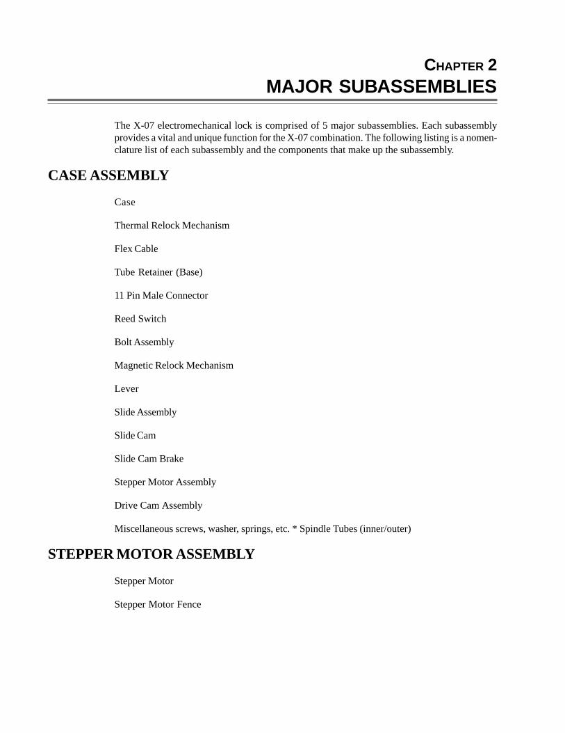
The X-07 electromechanical lock is comprised of 5 major subassemblies. Each subassemblyprovides a vital and unique function for the X-07 combination. The following listing is a nomen-clature list of each subassembly and the components that make up the subassembly.
CASE ASSEMBLY
Case
Thermal Relock Mechanism
Flex Cable
Tube Retainer (Base)
11 Pin Male Connector
Reed Switch
Bolt Assembly
Magnetic Relock Mechanism
Lever
Slide Assembly
Slide Cam
Slide Cam Brake
Stepper Motor Assembly
Drive Cam Assembly
Miscellaneous screws, washer, springs, etc. * Spindle Tubes (inner/outer)
STEPPER MOTOR ASSEMBLY
Stepper Motor
Stepper Motor Fence
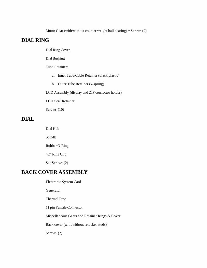
Motor Gear (with/without counter weight ball bearing) * Screws (2)
DIAL RING
Dial Ring Cover
Dial Bushing
Tube Retainers
a. Inner Tube/Cable Retainer (black plastic)
b. Outer Tube Retainer (x-spring)
LCD Assembly (display and ZIF connector holder)
LCD Seal Retainer
Screws (10)
DIAL
Dial Hub
Spindle
Rubber O-Ring
“C” Ring Clip
Set Screws (2)
BACK COVER ASSEMBLY
Electronic System Card
Generator
Thermal Fuse
11 pin Female Connector
Miscellaneous Gears and Retainer Rings & Cover
Back cover (with/without relocker studs)
Screws (2)
CHAPTER 3X-07 OPERATION
A BRIEF DESCRIPTION OF HOW THE LOCK OPERATES:
1 The X-07 cover assembly is comprised of the back cover, generator, and the system elec-tronic card. The electronic card receives pulses from the generator as the dial is turned.These pulses are then rectified and used to charge up a super capacitor. The super capacitorprovides the operating voltage for the entire lock. The super capacitor will maintain poweron the system card for approximately 90 seconds after dialing has stopped. Although thesystem card will maintain power for 90 seconds, its microprocessor will power off the LCD40 seconds after the last pulse has been received from the generator. The microprocessormay be the brains of the X-07, but without the generator pulses it could not determine whatto do or when to do it.
2. The microprocessor makes all of its decisions directly, or indirectly, from the interpretation ofthe inputted generator pulses. These pulses provide the required information for the micro-processor to indicate the dial position, dial direction and the speed the dial is being turned bythe user. The direction is determined by the phase relationship of the pulses, and the positionis determined by the number of pulses that are received as the dial is being turned. Themicroprocessor has several software routines that constantly monitors all input pulses todetermine if any security violations have occurred during the dialing process. If a violationhas occurred, the microprocessor will turn on the lightning bolt to indicate an error at the endof the function or operation and will not allow the lock to open.
3. The following is a list of functions that are monitored by the X-07 microprocessor:
a. Time pulse duration
Determines how fast the dial is being turned. If too fast, will not fire motor after “OP”.
b. Counts number of pulses
For updating dial position
How far did dial turn without pausing - Maximum is 1 1/3 revolutions;
c. Monitors phase relationship of pulses
Determines and establishes direction of changes
Writes the correct arrow symbol to the display
Compares the entered combination to the lock’s combination;
d. Check delay between sets of pulses
Wrist delay should be at least ¼ second between turns;
e. Check delay between direction change
Dial turn around should be at least ¼ second between turns.
4. Upon power up, the microprocessor reads and determines the phase relationship for initialdial position. The microprocessor will output a two digit number and an arrow symbol for dialposition and direction to the display driver. The display driver then outputs this information tothe LCD through the 11 pin connector. The microprocessor will continually update the LCDas the dial is turned by counting pulses and sampling phase relationships. When a directionchange is detected, the microprocessor will generate a new random number and write thenew number with the opposite arrow symbol to indicate the new direction and dial position.This process will be continued as long as the dial is being turned, or until the required numberof direction changes have been detected.
5. When a direction change occurs, the microprocessor saves the last number it wrote to theLCD driver. This number will be compared to the correct combination when the dial isturned clockwise after it has detected the last number of the combination. A correct combi-nation alone is not enough to open the lock. The system software has several routines thatcheck and validate the dialing process. If any of these are violated, the X-07 microprocessorwill not open the lock but will instead turn on the lightning bolt symbol to indicate a securityviolation. If no violation has occurred, the microprocessor will write “OP” to the displaydriver and fire the stepper motor after the reed switch is activated, assuming the dial speedis correct.
6. The reed switch is a magnetically sensitive device that will close a circuit when a magneticfield is passed near it. The X-07 has a reed switch mounted in the case assembly and a smallmagnet mounted on the drive cam. The position of the magnet on the drive cam determineswhen the reed switch will be activated. As the dial is turned, the magnet will pass over thereed switch, once for each revolution of the dial. Therefore, the microprocessor will fire thestepper motor within one revolution of the dial after “OP” is displayed on the LCD.
7. After the microprocessor has fired the stepper motor, the following mechanical sequence ofevents will occur to open the X-07 lock.
a. The stepper motor gear will be in position for engagement with the drive cam gear teeth.
b. Drive cam is being driven by the user turning the dial.
c. As the drive cam teeth engage the stepper motor gear teeth, the stepper motor gear willmove in the counterclockwise direction (viewed from the front of the dial).
d. As the stepper motor gear moves counterclockwise, it will rotate the slide cam.
e. The slide cam will move the slide down.
f. As the slide moves down, it will allow the lever assembly to move into the proper posi-tion to be engaged by the drive cam.
g. The lever assembly is attached to the bolt mechanism and when moved in the directionaway from the bolt by the drive cam, it will retract the bolt.
h. Continuing to turn the dial in the clockwise direction will move the lever assembly andbolt to their full limit of travel (viewed from front of dial).
i. The dial can only be turned in the clockwise direction until the bolt is fully retracted.
j. With the bolt fully retracted, the X-07 lock is open.
8. To lock the X-07, the container locking bars must have been moved to the locked or ex-tended position and then the dial must be turned in the counterclockwise direction (whenviewed from the front of dial) until the X-07 bolt is fully extended. As the dial is turned in theCCW direction, the following sequence of events will occur to lock the container.
a. The drive cam gear teeth will turn the stepper motor gear CW to its home position(viewed from the front of the dial.)
b. As the stepper motor is being reset, the slide cam will also be rotated back to its homeposition.
c. As the slide cam rotates, it will move the slide up to its home position.
d. The slide will lift the lever assembly, disengaging it from the drive cam, freeing the leverassembly to extend the bolt to the locked position.
e. When the lever reaches its home position, resting against the slide assembly stop, thebolt will be fully extended between the container locking bars.
f. The dial is now free turning, and the X-07 is scrambled (locked position).
g. The correct combination must be executed to open the lock again.
CHAPTER 4TROUBLESHOOTING X-07 PROBLEMS
LIGHTNING BOLT AFTER DIALING COMBINATION
Symbol displayed to indicate a software protective security feature has been violated by the useror incorrect combination entered.
POSSIBLE CAUSES TO SECURITY FEATURES VIOLATIONS
1. Wrong combination.
2. Dialing the combination in less than 15 seconds.
3. Turning the dial more than 1 and 1/3 revolutions without pausing.
4. Turning dial without pausing for a ¼ second between turns.
5. Turning dial without pausing for a ¼ second on direction changes.
6. Backup dialing.
WRONG COMBINATION
Make every effort to validate the combination. Remember on a combination change the combi-nation is not written to memory until the lock displays “OP”. Often users do not go back and tryopening the lock with the previous combination.
DIALING THE COMBINATION IN LESS THAN 15 SECONDS
This is very easy to do if the X-07 random number generator generates a number on a directionchange that is relatively close to the next number in the combination sequence. If this occurred,go past your number and stop on it the next time around.
TURNING THE DIAL MORE THAN 1 AND 1/3 REVOLUTIONS -
Physically this is hard to do, but if your dialing technique is with very short and slow movementsof the dial the X-07 may interpret this dialing method as being one continuous movement of thedial.
TURNING DIAL WITHOUT PAUSING FOR A ¼ SECOND BETWEEN TURNS -
See recommendation for dialing (below)
TURNING DIAL WITHOUT PAUSING FOR A ¼ SECOND ON A DIRECTION CHANGE
Experienced mechanical lock users have a difficult time with this security feature. They dial tothe number and reverse direction with the same grip of the dial. You must pause during directionchanges for ¼ of a second.
BACKUP DIALING
This method should always be avoided if experiencing lightning bolts.
RECOMMENDATION FOR DIALING
1 . When experiencing difficulty in opening the lock, it’s highly recommended the user use astrict dialing procedure to execute the combination. One such method is for the user to graspthe knob between the thumb and the index finger of the right hand, with the palm facingupward, and with the thumb pointing to the 3 o’clock position for CCW dialing. With thisposition established, the user simply rotates the wrist to the left until the palm is facing downand the thumb is pointing to the 9 o’clock position. At the 9 o’clock position, the user releasesthe knob and repeats the procedure until they are within 10 digits of the desired number. Atthis time the user may walk the dial to the desired number with his/her finger tips.
2. This procedure is reversed for CW dialing. The user grasps the dial with the right hand, withthe palm down, and the thumb pointing to the 9 o’clock position. A simple wrist turn to theright until the palm points up and the thumb is pointing to the 3 o’clock position. Release andrepeat procedure until the desired number is reached in the CW direction.
3. This may seem to be over simplification for executing the combination, but it will give thedesired results for anyone having difficulty in dialing the lock. Just by grasping, wrist turning,and releasing the dial, it will help to eliminate security violations for first time users.
X-07 WILL NOT POWER UP AND THE CONTAINER IS OPEN
The dial has been turned in either direction for several revolutions and the display does not showany symbols or numbers.
POSSIBLE CAUSES:
1. Security violations.
2. Hub assembly, or cam assembly insert loose.
3. Faulty LCD, bad cable connection or flex cables damaged.
4. Electronic card failure.
SECURITY VIOLATION
1. Exceeded maximum error count without getting “OP”.
a. Ten (10) errors in succession will cause the X-07 lock to blank out the LCD. The LCDwill remain off until the lock has totally powered off. Power off occurs 90 seconds afterdialing has stopped.
b. If you do not stop dialing for 90 seconds the electronics will remain powered up and theLCD will stay blank.
c. Confirm your combination and dialing techniques.
HUB ASSEMBLY SET SCREWS LOOSE, OR CAM ASSEMBLY INSERT LOOSE
1 . Gain access to the cam assembly by removing the back cover. (See appendix A)
2. Hold the cam with one hand and turn the dial with the other. The dial should not turn.
If the dial turns, determine if it is the cam insert or the hub set screws that are causing theproblem.
If the dial turns independently of the spindle and drive cam, then the hub set screws areloose.
If the drive cam turns independently of the spindle and dial, then the cam insert is loose.
3. Replace required parts.
FAULTY LCD, BAD CABLE CONNECTION OR FLEX CABLES DAMAGED
1 To inspect the flex cables and check for proper connection, follow the instructions for Ap-pendix D.
2. If the display still fails after cables and connections are inspected, replace the LCD assem-bly.
3. If the cables are cut, or badly damaged, the case assembly must be replaced.
ELECTRONIC CARD FAILURE
1 . Replace the back cover with a new one and check out the lock.
X-07 WILL NOT POWER UP AND THE CONTAINER IS LOCKED
The dial has been turned in either direction for several revolutions and the display does not showany symbols or numbers.
POSSIBLE CAUSES:
1 . Security violation.
2. Hub assembly set screws loose.
3. Drive cam assembly insert loose.
4. Faulty LCD or card failure.
SECURITY VIOLATION
1 . Exceeded maximum error count without getting “OP”.
a. Ten (10) errors in succession will cause the X-07 lock to blank out the LCD. The LCD willremain off until the lock has totally powered off. Power off occurs 90 seconds after dialinghas stopped.
b. If you do not stop dialing for 90 seconds the electronic will remain powered up and the LCDwill stay blank.
c. Confirm your combination and dialing techniques.
HUB ASSEMBLY SET SCREWS LOOSE OR GROOVED ON SPINDLE -
Dial turns independently of spindle; no generator feedback (rasping) is detected.
1 . Gain access by following directions in Appendix C.
2. Separate hub assembly from dial; replace hub assembly onto spindle, tighten set screws, turnhub to power up X-07 lock.
3. Execute combination and open container.
4. Replace dial assembly with new one.
DRIVE CAM ASSEMBLY INSERT LOOSE
1 Check for generator feedback (rasping) as you turn the dial and spindle with your finger tips.If you CAN hear the feedback, proceed to faulty LCD (Appendix E), otherwise continue byfollowing instruction in Appendix F.
2. If you are successful in powering up the lock and can execute the combination, open thecontainer.
3. Replace the drive cam and dial assemblies following the instructions in Appendix B.
FAULTY LCD, BAD CONNECTION, OR FLEX CABLES SEVERED
1. Follow instructions in Appendix E.
2. Follow instructions in Appendix I
ELECTRONIC CARD FAILURE
1 . There is not a lot that can be done at this point. If time permits, let the X-07 sit idle for 72hours to allow the stored power in the super capacitor to discharge to a minimum level, thentry to power up with quick half turns of the dial.
2. A sharp blow on the container (at the 5 o’clock position) with a dead blow hammer MAYmake a loose connection and allow the X-07 lock to power up.
3. If unsuccessful, see forced entry. (Appendix H)
DIALING RESTRICTED
POSSIBLE CAUSES
1. Improper clearance between dial assembly and dial ring cover assembly.
2. Dial ring assembly installed off center.
3. Bent spindle.
4. Generator gears binding.
5. Motor gear installed 180 degrees out of sync.
CLEARANCE BETWEEN DIAL ASSEMBLY AND DIAL RING COVER ASSEMBLY
1 . Gage was not used and/or spindle has been cut too short.
2. Requires replacement of the dial assembly and/or spindle.
DIAL RING ASSEMBLY INSTALLED OFF CENTER
Requires realignment of the dial ring.
See Figure 11.
1. Execute combination to open container.
2. Pull out the drawer, release the interlock, and extend the locking bars to the locked position.
3. Turn the X-07 dial to extend the bolt into the locked position.
4. Follow the instructions for Appendix B.
5. Remove the dial ring cover from the dial ring assembly by removing the two Phillips screws.
6. Loosen the two screws INSIDE the dial ring, being careful not to damage the flexcables.
These screws are in slotted holes to allow centering of LCD display and dial assembly.Once loosened you should be able to turn the dial ring slightly to the left and right on thecontainer.
7. Reinstall the dial assembly, drive cam, and cam screw. Tighten the cam screw.
8. Move dial ring around until dial assembly turns freely.
9. Remove cam screw, drive cam, and dial assembly, tighten the inside dial ring screws.
10. Replace the dial ring cover dial assembly, drive cam and screw, and back cover assembly.
11. Check out lock for any problems.
BENT SPINDLE
1. Execute combination and open container.
2. Pull out the drawer, release the interlock and extend the locking bars into the locked position.Turn the X-07 dial to extend the bolt into the locked position.
3. Follow instructions for Appendix B.
4. Inspect spindle on dial assembly.
5. If bent, then replace spindle and dial assembly.
GENERATOR GEARS BINDING
1. Follow instructions in Appendix A.
2. Inspect generator gear teeth (3 gears on back cover electronic card) for damage. If dam-aged, replace all three gears.
3. Gear teeth binding from foreign substance. Remove foreign substance.
MOTOR GEAR INSTALLED 180 DEGREES OUT OF SYNC.
1. This can happen if the motor was installed without fully extending the lock bolt.
2. Remove the motor and follow instructions in Appendix G.
DIAL RESTRICTED TO THE RIGHT AFTER “OP”
After executing the combination and with “OP” displayed, the X-07 dial is restricted whenturned to the right. When the dial is turned back to the left and “OP” goes out, the dial is freeturning.
First, a bit of information about the containers and the locking bars. The bars are two equallengths of hardened steel that extend out of the container drawer head and into the side walls ofthe container. When extended, the locking bars prevent any movement of the drawer head.When retracted, these bars are clear of the container walls and allow the container drawer to bepulled out of the container.
When the locking bars are extended, the container locking mechanism is designed to leave aspace between the locking bars that is sufficient for the X-07 bolt to extend into, yet smallenough to restrict the travel of the locking bars when the container is closed and the X-07 bolt isextended between them.
1. X-07 bolt may be binding or jamming as it is retracted from the gap between locking bars.
2. After executing the combination and with “OP” displayed, turn the dial slowly to the rightwhile feeling and listening for the slide mechanism to engage.
3. If you feel the mechanism has engaged, do the following:
a. Slightly force the dial to the right adding force as you attempt to open. Hold pressure onthe container handle toward the closing direction or “jiggle” the handle.
b. Open drawer and remove dust cover and check the gap between the container lockingbars for sufficient space to accommodate the X-07 bolt.
c. Inspect bolt on the X-07 for gouges and scratches from scraping on bars.
d. Make adjustment (usually by grinding or filing locking bars) and replace parts as re-quired.
DIAL RESTRICTED WHEN CLOSED/TURNS FREELY WHEN CON-TAINER OPEN
First, a bit of information about the containers and the locking bars. The bars are two equallengths of hardened steel that extend out of the container drawer head and into the side walls ofthe container. When extended, the locking bars prevent any movement of the drawer head.When retracted, these bars are clear of the container walls and allow the container drawer to bepulled out of the container.
When the locking bars are extended, the container locking mechanism is designed to leave aspace between the ‘ locking bars that is sufficient for the X-07 bolt to extend into, yet be smallenough to restrict the travel of the locking bars when the container is closed and the X-07 bolt isextended between them.
Note: If the lock has just been opened the X-07 dial will be blocked to the rightwith
container drawer shut and the handle in the locked position until the dial is suc-cessfully turned to the left to reset the stepper motor. Remember that theX-07 bolt is in the open position and its bolt is fully retracted. Therefore,you will experience a block to the right under this condition. The blockright is normal and is not the error condition.
1. The X-07 bolt is blocked or binding as it is extended into the gap between thelocking bars.
a. Open drawer and remove the drawer head cover plate and check gap between thelocking bars for sufficient space to accommodate the X-07 bolt.
b. Check locking bars seating area on container wall for scrapes or indications that thedrawer is not properly aligned.
2. The locking bars cannot seat into container wall.
a. Check locking bars seating area on container wall.
b. Check drawer alignment to container.
MISSING OR EXTRA SEGMENTS ON LCD
The LCD cannot be accurately interpreted due to missing or extra segments.
Even though the majority of the time the failure for missing or extra segments will be due to theflex cable, the procedure that follows is designed to provide instruction for gaining access to thelock for replacing the display. If the instructions are followed correctly, the user may inspect theflex cable for damage anytime before replacing the display assembly. In other words, theseinstructions will require the user’s judgment in determining the cause of the problem.
Two important questions must be asked before proceeding. First, can the numbers be accuratelyinterpreted; and secondly, is the container open or closed.
POSSIBLE CAUSES
1. LCD
2. Flex Cable
3. Cover Assembly
CONTAINER IS OPEN
1 . Follow instructions in Appendix D.
CONTAINER IS CLOSED, NUMBERS CAN BE ACCURATELY ESTIMATED
1 . Execute combination and open container.
2. Follow instructions in Appendix D.
CONTAINER IS CLOSED, NUMBERS CANNOT BE ACCURATELY INTERPRETED
1. Check ribbon cable and splice if possible to open container. See Appendix I.
2. If unable to open the container, follow instructions in Appendix E.
BLACK SPOTS ON LCD
The display has black spots. First, can the numbers be accurately interpreted, and secondly, isthe container open or closed?
Container is open.
Follow instructions for Appendix D.
Container is closed, numbers CAN be accurately interpreted. Execute combination andopen container.
Follow instructions for Appendix D.
Container is closed, numbers CANNOT be accurately interpreted.
If the display problem is severe black spots, try heating the display slightly with a hot air device(hair dryer). Exercise patience, restrict the amount of heat to be applied at first. You canincrease the intensity as time goes by. If you are successful, proceed to instructions for Appen-dix D. If heating the display does not work, proceed by following the instructions for Appendix E.
Replace parts where necessary.
DIAL COMBINATION, GET “OP”. BUT DIAL IS FREE SPINNING
Assumption here is that the container is closed.
If container is open follow instructions for Appendix B and replace whatever parts necessary.
POSSIBLE CAUSES
1. Back cover assembly (electronic card).
2. Hub set screw loose or grooved on spindle.
3. Drive cam assembly insert loose.
4. Stepper motor fails to step.
BACK COVER ASSEMBLY (ELECTRONIC CARD)
Extremely low probability since the lock did execute the combination properly and “OP” goingout indicates that the reed switch is detected.
HUB SET SCREW LOOSE OR GROOVED ON SPINDLE
1. May have enough torque to power up the X-07 but not enough to pull the X-07 bolt. Try todetermine if you can feel any feedback (rasping) from the generator being turned after“OP” is displayed.
2. If you suspect hub set screws are loose (dial turns independently of spindle or can be pulledtowards you off of spindle), follow instructions in Appendix C.
DRIVE CAM ASSEMBLY, INSERT LOOSE
1. May have enough torque to power the X-07 but not enough to pull the X-07 bolt. Try todetermine if you can feel any feedback (rasping) from the generator being turned after“OP” is displayed.
2. If you suspect the cam insert is loose (dial and spindle turning together and feels securelyattached to spindle), follow instructions in Appendix F.
STEPPER MOTOR FAILS TO STEP
The problem may be the stepper motor has a dead spot in the home position and will not step tothe cam engagement position.
Objective is to move stepper motor off the dead spot with vibrations. Several methods havebeen very successful. But first, enter the combination up to the last digit and perform one of thefollowing before turning the dial to the right to get the “OP”.
1 . Moving the container handle up and down vigorously will sometimes generate enough vibra-tion from the locking bars striking the X-07 bolt to move the motor off the dead spot.
2. Hitting the container with a deadblow hammer, heavy rubber mallet or a small sledge ham-mer with a legal pad as padding at the 5 o’clock position on the container next to the dial ringwill sometimes provide the desired results.
CAUTION: Never hit the dial ring or the LCD.
3. A variable speed hammer drill with a dowel pin or center punch installed in the chuck hasworked extremely well at times. The best approach with this method is to turn the dial to theright within a couple of seconds after starting the vibration and continue the vibration for atleast two complete revolutions of the dial. The speed of the drill setting appears to vary from
lock to lock. Some have opened right up with a slow speed setting and others at a much fasterspeed.
4. The hammer drill works even better if you remove the dial (Appendix C) and apply thevibrations to the hardplate. To get directly to the hardplate after removing the dial, drill a ¼inch hole through the dial ring assembly and the drawer head skin. DO NOT DRILL INTOTHE HARDPLATE! The position of the ¼ inch hole should be about 1 ½ inches down and1 inch to the right of the spindle hole. This should place you close to the stepper motor.
5. If a hammer drill is not available and entry is urgent, try using a center punch with a light-weight hammer. Tap the center punch as someone else is turning the dial to the right.
NOTE: Do not engage in either long enough to allow the lock to power downbefore turning the dial to the right. You must have enough power on thelock to fire the stepper motor to get the container open.
“OP” WILL NOT GO OUT WHEN DIALED TO LEFT
If the microprocessor does not turn off “OP” when the dial is turned back to the left, it is highlyprobable the microprocessor did not receive a signal from the reed switch that indicates camposition. After the processor displays “OP” it will go into a program loop waiting for the reedswitch to make. If the processor never sees the reed switch go active it will remain in a loop untilthe lock powers off.
POSSIBLE CAUSES
1. Reed switch
2. Cam magnet
3. Back cover (electronic card)
REED SWITCH
The fact “OP” did not go off indicates that the processor did not read the cam position signal.This also indicates that the reed switch and/or magnet may be marginal or defective. Since bothcomponents have a very low failure rate, the probability that one is marginal is the basis for ourapproach to this problem.
1. Setup, dial combination stopping on the last digit.
2. Bias the dial outwardly to move the magnet closer to the reed switch. To accomplish this,grip the dial knob with vise grips and pull toward the front of the container while turning thedial to the right. With luck, “OP” will be displayed; the reed switch will make; the bolt will beretracted and the container can be opened.
3. If the above does not work, we recommend the dial be removed following instructions in
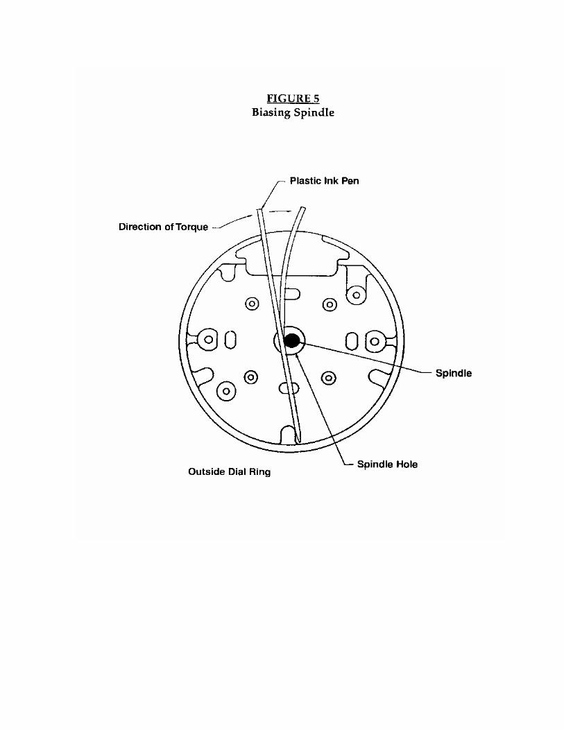
Appendix B if the container is open, or Appendix C if the container is closed (to allow for moreside play in the spindle). The increased side play may allow the cam magnet to get closer tothe reed switch. If the container is open, check the reed switch to make sure it is not tilted toone side. Replace the drive cam with a new one and try the lock. If the container is closed,remove the dial as stated in Appendix C and bias the spindle away from the ribbon cables(opposite the direction shown in Fig. 5).
CAM MAGNET
Same approach as the reed switch.
BACK COVER ASSEMBLY
1. Remove back cover. (Appendix A)
2. Replace the back cover assembly with a new one.
DIAL BLOCKED TO THE RIGHT AFTER “OP”
After executing the combination and with “OP” displayed, the X-07 dial is blocked to the right.When the dial is turned back to the left and “OP” goes out the dial is free turning and thecombination can be reentered.
POSSIBLE CAUSES
1. Stepper motor gear
2. Mechanical relocker
3. Magnetic relocker
STEPPER MOTOR GEAR
If the stepper motor does not take a full 36 degree step when the X-07 processor outputs thesignal to step the motor, then the stepper motor gear teeth will not be properly aligned to the camdrive gear teeth. The cam drive gear teeth and the stepper motor gear teeth will not meshproperly and may be hitting on top of each other creating a block to the right. If this is the case,we may be able to move the stepper motor a slight amount by inducing some vibrations with adead blow hammer while walking the dial into and out of the block. If you back up too far thecam will reset the stepper motor to the home position and you will lose the block. Hold and turnthe dial with one hand while hitting the container with the other. You can increase the intensityas time passes. Start out cautiously and increase the intensity as time passes.
MECHANICAL RELOCKER
The thermal fuse pad on the back cover assembly compresses the relocker lever spring and liftsthe relocker lever up and away from the slide assembly tab. When the relocker lever is held up,the slide assembly tab will move under it without any resistance. If for any reason the relocker
lever spring is not completely compressed the relocker lever will only be partially lifted. Thismay result in the slide assembly tab being blocked as the dial is turned to the right. The followingis a list of the possible causes for the relocker failure.
1 . Back cover assembly mounting screws are loose.
If the back cover assembly mounting screws are loose, you may be able to use a deadblowhammer to open the lock. First you must get a dial block right by dialing the correct combi-nation. When you get “OP”, hold light turning pressure clockwise (right) while hitting thecontainer just outside the dial ring assembly. You must vibrate the back cover assemblyenough to overcome the mechanical relock spring.
2. Thermal fuse has melted or is indented.
3. Relocker lever is not lifted enough to allow slide to move.
MAGNETIC RELOCKER
The magnetic relocker is a pin device mounted on an angle into the X-07 bolt. If a strongmagnetic field is placed near the device it will fire the pin into the case assembly guide track inwhich the bolt travels back and forth. Once the pin has fired, all movement of the bolt toward theopen position will be blocked.
NOTE: Vibrating the container handle and/or using a deadblow hammer strik-ing at the 5 o’clock position outside the dial ring may reset the magneticrelock pin if your lock is mounted in the VD (Vertical Down) or LH (LeftHand) position.
DIAL BLOCKED LEFT AND RIGHT ON COMBINATION CHANGE
The X-07 dial can only be turned ¼ revolution in either direction after opening the container andinserting the change key. Dial block left and right on initial dialing of the combination is usuallycaused by the container locking rods blocking the X-07 bolt.
First, a bit of information about the containers and the locking bars. The bars are two equallengths of hardened steel that extend out of the container drawer head and into the side walls ofthe container. When extended, the locking bars prevent any movement of the drawer head.When retracted, these bars are clear of the container walls and allow the container drawer to bepulled out of the container.
When the locking bars are extended, the container locking mechanism is designed to leave aspace between the locking bars that is sufficient for the X-07 bolt to extend into, yet smallenough to restrict the travel of the locking bars when the container is closed and the X-07 bolt isextended between them.
Remember, when changing the combination, the container drawer must be out and in the lockedposition. That is, the container locking handle must be in the up position.
1 . Locate the interlock release, usually located near the locking bolts on the outer perimeter ofthe drawer head. Different container manufacturers have different interlock releases, soplease take the time to locate it and then press, pull, and/or slide the interlock release whilemoving the locking handle to the locked position. See Figure 12 for some sample locations.
2. If the drawer is in the locked position and the container’s locking bolts are extended, the X-07 dial can now be turned in either direction, without any restriction, blockage, or interfer-ences.
3. A quick check for the above is to move the container locking handle up and down whileobserving the locking bolts being extended and retracted.
4. Start execution of a combination change by turning the dial in the counterclockwise (CCW)direction for several full revolutions. The X-07 will become operational and ready to accepta combination when the display shows a left arrow and numbers. The left arrow indicatesdirection and the numbers indicate dial position.
SETTING A COMBINATION WITH THE CARD SERIAL NUMBER
Original combination has been lost, container open.
If a container is open, it is possible to change the combination on the container without the oldcombination. Remove the backplate and record the lock serial number. It will be a six digitnumber like 003375. Use the six numbers as a combination number = 00-33-75. Dial an incor-rect combination to obtain the lightning bolt. Insert the change key into the back of the lock.Enter the serial number as a combination, (00-33-75). When the letters SL appear for “SelectMode” continue changing the combination in the normal manner to your new combination.
Original combination has been lost, container closed.
See forced entry. (Appendix H)
CHANGE KEY LOCKED IN CONTAINER
If the change key is left inserted in the X-07 lock and the container gets locked, you can open thecontainer by executing the audit trail (successful lock opening) from a power off state. The X-07 system software was designed to ignore the change key when executing the combinationfrom the audit trail routine.
1. Allow the X-07 to power off, stop dialing for 90 seconds or more.
2. After 90 seconds plus delay, start dialing to the right (CW) until the audit trail starts flashing(count for successful lock openings). Then simply reverse direction (CCW) and executeyour old combination in the normal manner.
3. Caution, you get one attempt per power down of the lock. If you miss dial and get alightning bolt, you must power down before attempting again.

4. Repeat the steps for changing the combination. When PO is displayed, pull out the changekey. The display will show CC. You must confirm the new combination by entering it untilOP is displayed and the bolt is retracted. At that point the new combination is stored in themicroprocessor.

APPENDICES
APPENDIX A
REMOVING THE BACK COVER ASSEMBLY
1 Remove the drawer head cover plate.
2. Remove the back drill pate and filler plate.
3. Remove the X-07 back cover assembly.
Remove the two screws on perimeter of the back cover assembly. One is on the end of coverassembly and the other is on the side. Both screws are Phillips head screws and require a #2Phillips screw driver.
Lift the cover assembly out perpendicular to the lock assembly. Care must be exercised herebecause the female connector on the system card mates up with an 11 pin male connector on thecase assembly. If removed at a severe enough angle, the 11 pin male connectors may have oneor more pins slightly bent. Even a slightly bent pin may prevent, or inhibit, the reinstallation of thecover assembly.
APPENDIX B
REMOVING THE X-07 DIAL (CONTAINER OPEN)
1 Remove the drawer head cover plate.
2. Remove the back drill plate and filler plate.
3. Remove the X-07 back cover assembly.
Remove the two screws on perimeter of the cover assembly. One is on the end of coverassembly and the other is on the side. Both screws are Phillips head screws and require a#2 Phillips screw driver.
Lift the cover assembly out perpendicular to the lock assembly. Care must be exercisedhere because the female connector on the system card mates up with an 11 pin male con-nector on the case assembly. If removed at a sever enough angle, the 11 pin male connec-tors may have one or more pins slightly bent. Even a slightly bent pin may prevent, or inhibit,the reinstallation of the cover assembly.
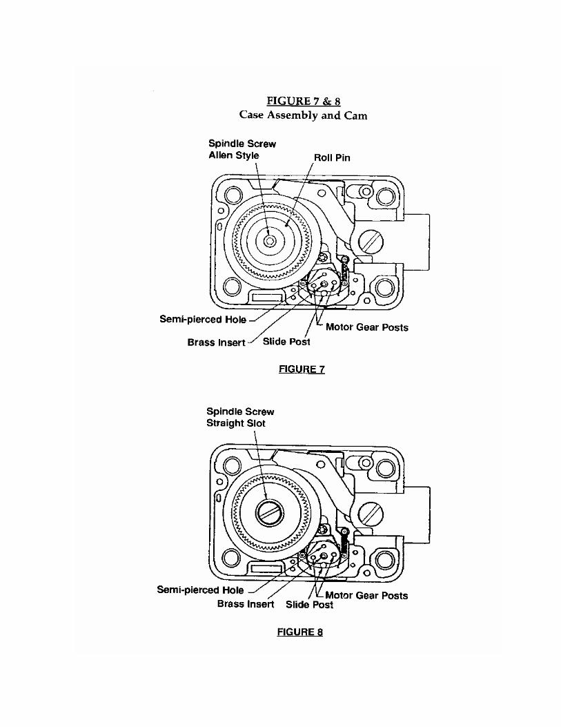
4. With cover assembly removed, remove the straight slot/hex screw (depending on type ofscrew) from center of cam. (See Figs. 7 & 8) This screw attaches the drive cam to thespindle.
5. With screw removed, remove the drive cam from the spindle.
6. Remove the dial assembly and spindle by pulling on the dial knob from the front.
APPENDIX C
REMOVING THE X-07 DIAL (CONTAINER CLOSED)
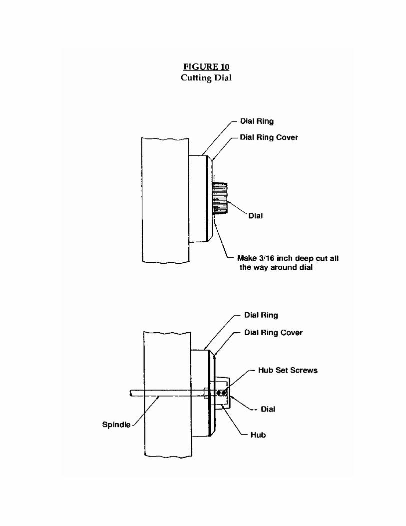
1 To remove the dial, cut off the knob close to the dial. (See Fig. 10)
2. Make a continuous vertical cut around the knob and parallel to the dial.
3. Pull the knob off with vise grips.
4. Loosen hub set screws.
5. Remove hub and dial.
Note: Hub assembly may be placed back on spindle with set screws tightened toturn spindle.
APPENDIX D
REPLACEMENT OF THE LCD (CONTAINER OPEN)
1. Pull out the drawer, release the interlock, and extend the locking bars to the locked position.
2. Remove the drawer head cover plate.
3. Remove the back drill plate and filler plate.
4. Remove the X-07 cover assembly (backplate).
Remove the two screws on perimeter of the cover assembly. One is on the end of coverassembly and the other is on the side. Both screws are Phillips head screws and require a#2 Phillips screw driver.
Lift the cover assembly out perpendicular to the lock assembly. Care must be exercisedhere because the female connector on the system card mates up with an 11 pin male con-nector on the case assembly. If removed at a severe enough angle, the 11 pin male connec-tors may have one or more pins slightly bent. Even a slightly bent pin may prevent, or inhibit,the reinstallation of the cover assembly.
5. With cover assembly removed, remove the straight slot/hex screw (depending on type ofscrew) from center of cam. (Fig. 7 & 8) This screw attaches the drive cam to the spindle.
6. With screw removed, remove the drive cam from the spindle.
7. Remove the dial assembly and spindle by pulling on the dial knob from the front.
8. Remove the dial ring cover and the black plastic inner tube retainer by removing the Phillipshead screws.
9. At this stage, the display can now be removed and replaced by removing or loosening thedisplay retainer spring screw(s). In the newer versions, the ZIF connector holder is sepa-rate from the LCD display, so that both would have to be replaced.
10. Unplug the two flex cable leads by pulling the ZIF locking levers up off the connectors.
11. Plug the two flex cable leads back into the new connector and push the locking lever backdown onto the connector. Make sure that the Five Wired set goes into the Five Slot set andthe Four Wired set goes into the Four Slot set. The flex cable leads are plugged into theconnector with the circuit lands facing down (silver side down). The display and ZIF con-nector holder are then installed into the dial ring and retainer clip with the flex cables facingout towards the front of the lock.
CAUTION: In the newer version of ZIF seal holder, you MUST place the screwtab UNDER the screw tab of the outer tube retainer. Otherwise the flexcables may be cut by the dial ring cover.
12. Replace the tube retainer, dial ring cover, cam, dial and back cover.
APPENDIX E
REPLACEMENT OF THE LCD (CONTAINER CLOSED)
1. To remove the dial, cut off the knob close to the dial. (See Fig. 10)
2. Make a continuous vertical cut around the knob and parallel to the dial.
3. Pull the knob off with vise grips.
4. Loosen hub set screws.
5. Remove hub and dial. (Hub to be reinstalled later to open lock).
6. Remove the dial ring cover and the inner tube retainer by removing the Phillips head screws.
7. At this stage, the display can now be removed and replaced by removing or loosening thedisplay retainer spring screw(s). In the newer versions, the ZIF connector holder is sepa-rate from the LCD display, so that both would have to be replaced.
8. Unplug the two flex cable leads by pulling the ZIF locking levers up off the connectors.
9. Plug the two flex cable leads back into the new connector and push the locking lever backdown onto the connector. Make sure that the Five Wired set goes into the Five Slot and theFour Wired set goes into the Four Slot set. The flex cable leads are plugged into the con-nector with the circuit lands facing down (silver side down). The display and ZIF connectorholder are then installed into the dial ring and retainer clip with the flex cables facing outtowards the front of the lock.
CAUTION: In the newer version of ZIF seal holder, you MUST place the screwtab UNDER the screw tab of the outer tube retainer. Otherwise the flexcables may be cut by the dial ring cover.
10. Replace the hub that was removed above and tighten the set screws.
11. Execute combination and open container.
12. Remove the drawer head cover plate, back drill plate, and filler plate.
13. Remove the X-07 cover assembly (backplate).
Remove the two screws on perimeter of the cover assembly. One is on the end of coverassembly and the other is on the side. Both screws are Phillips head screws and require a#2 Phillips screw driver.
Lift the cover assembly out perpendicular to the lock assembly. Care must be exercisedhere because the female connector on the system card mates up with an 11 pin male con-nector on the case assembly. If removed at a sever enough angle, the 11 pin male connec-tors may have one or more pins slightly bent. Even a slightly bent pin may prevent, or inhibit,the reinstallation of the cover assembly.
14. Replace the dial and hub with new parts.
APPENDIX F
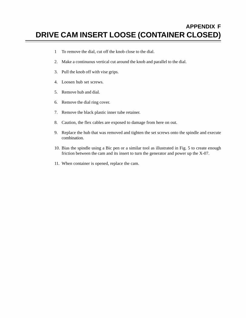
DRIVE CAM INSERT LOOSE (CONTAINER CLOSED)
1 To remove the dial, cut off the knob close to the dial.
2. Make a continuous vertical cut around the knob and parallel to the dial.
3. Pull the knob off with vise grips.
4. Loosen hub set screws.
5. Remove hub and dial.
6. Remove the dial ring cover.
7. Remove the black plastic inner tube retainer.
8. Caution, the flex cables are exposed to damage from here on out.
9. Replace the hub that was removed and tighten the set screws onto the spindle and executecombination.
10. Bias the spindle using a Bic pen or a similar tool as illustrated in Fig. 5 to create enoughfriction between the cam and its insert to turn the generator and power up the X-07.
11. When container is opened, replace the cam.

APPENDIX G
REMOVING/INSTALLING STEPPER MOTOR AND CAM(CONTAINER OPEN)
1. Pull out the drawer, release the interlock, and extend the locking bolts to the locked position.
2. Turn the X-07 dial to the left until the bolt is fully extended.
3. Remove the drawer head cover plate.
4. Remove the back drill plate and filler plate.
5. Remove the X-07 cover assembly (backplate).
Remove the two screws on perimeter of the cover assembly. One is on the end of coverassembly and the other is on the side. Both screws are Phillips head screws and require a#2 Phillips screw driver.
Lift the cover assembly out perpendicular to the lock assembly. Care must be exercisedhere because the female connector on the system card mates up with an 11 pin male con-nector on the case assembly. If removed at a severe enough angle, the 11 pin male connec-tors may have one or more pins slightly bent. Even a slightly bent pin may prevent, or inhibit,the reinstallation of the cover assembly.
6. With cover assembly removed, remove the straight slot/hex screw (depending on type ofscrew) from center of cam. (Fig. 7 & 8) This screw attaches the drive cam to the spindle.
7. With screw removed, remove the drive cam from the spindle.
8. Remove the dial assembly and spindle by pulling on the dial knob from the front.
9. Locate the stepper motor in the case assembly. (Fig. 7, 8)
a. Oldest style has two Phillips head screws with a shield.
b. Newer style has two T-8 Torx mounting screws, without a shield.
10. Remove the stepper motor. (If it has a shield, remove it. Do not reinstall the shield).
11. To install the stepper motor with proper timing you must have the stepper motor gear in thehome position, and the X-07 bolt in the extended position.
a. To time the stepper motor, see Fig. 6.

12. Install stepper motor using two new Torx screws.
13. Install cam on the spindle and turn the dial in both directions to insure no binding beforereplacing the back cover assembly.
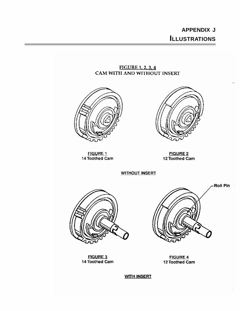
Please Note: If replacing an old style motor with a new style motor you must replacethe drive cam with a new style drive cam. To determine which cam you have,compare your cam to the drawings in (Fig. 1, 2, 3, or 4). The new style camhas two (2) extra teeth. The cams shown in Fig. 1 and Fig. 3 are the newstyle cams. Fig. 1 and Fig. 2 have a slotted screw and Fig. 3 and Fig. 4 havea hex screw. The cams in Fig. 2 and 4 are the old style, without the two (2)extra teeth.
14. Replace the back cover assembly.
APPENDIX H
FORCED ENTRY
The method used is often determined by answering the following two questions.
Urgency to gain entry.
Tools available.
Naval Facilities Engineering Service Center at Port Hueneme, California, has published a Tech-nical Data Sheet for Neutralizing lockouts of GSA Security Container using a heavy duty7-1/4 builder circular saw with a 6” x 1/8” abrasive cutoff blade. If you would like a copy of theabove document please call X-07 field service or you may contact the Naval Facilities Engineer-ing Service Group at (805) 982-1567.
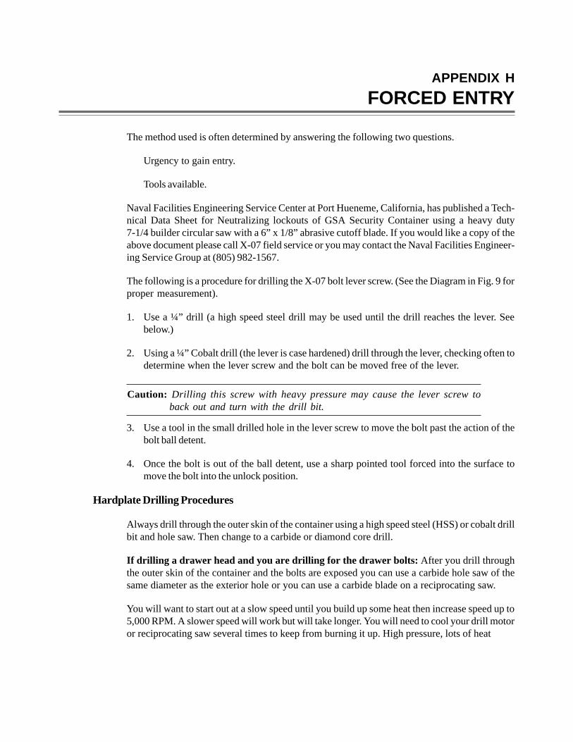
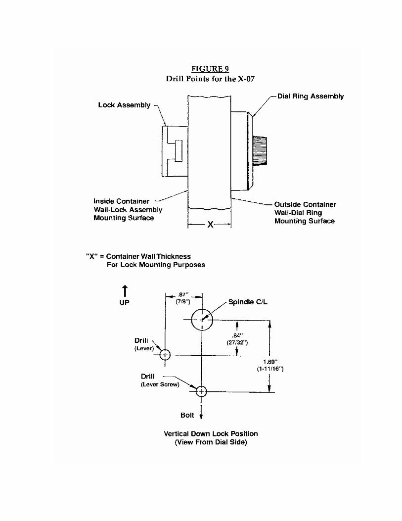
The following is a procedure for drilling the X-07 bolt lever screw. (See the Diagram in Fig. 9 forproper measurement).
1. Use a ¼” drill (a high speed steel drill may be used until the drill reaches the lever. Seebelow.)
2. Using a ¼” Cobalt drill (the lever is case hardened) drill through the lever, checking often todetermine when the lever screw and the bolt can be moved free of the lever.
Caution: Drilling this screw with heavy pressure may cause the lever screw toback out and turn with the drill bit.
3. Use a tool in the small drilled hole in the lever screw to move the bolt past the action of thebolt ball detent.
4. Once the bolt is out of the ball detent, use a sharp pointed tool forced into the surface tomove the bolt into the unlock position.
Hardplate Drilling Procedures
Always drill through the outer skin of the container using a high speed steel (HSS) or cobalt drillbit and hole saw. Then change to a carbide or diamond core drill.
If drilling a drawer head and you are drilling for the drawer bolts: After you drill throughthe outer skin of the container and the bolts are exposed you can use a carbide hole saw of thesame diameter as the exterior hole or you can use a carbide blade on a reciprocating saw.
You will want to start out at a slow speed until you build up some heat then increase speed up to5,000 RPM. A slower speed will work but will take longer. You will need to cool your drill motoror reciprocating saw several times to keep from burning it up. High pressure, lots of heat

and high speed will get you through.
Note: Some hardplates are work hardening. This means that when they start tocool, they will be harder than before you started drilling or sawing.
If you are drilling for the lever fence or the lever screw: If you are using a magnetic drilland are drilling with a diamond core bit the procedure is very different. You will want to drill at asteady speed of 500-550 RPM with a light steady pressure. You won’t see any chips whendrilling with a diamond core drill. You may see some very small filings but that is all.
APPENDIX I
TEMPORARY SPLICING OF RIBBON CABLE
Missing segments on the X-07 LCD are generally caused by a cut ribbon cable. If the segmentscan not be interpreted, you may be able to splice the cables well enough to get the lock open.
First you will need to remove the dial and dial ring assembly. Remove the inner and outer tubesif possible to prevent further damage to the cables. If the cables are cut anywhere on the outsideof the container, you can spice the cables if you are careful and patient.
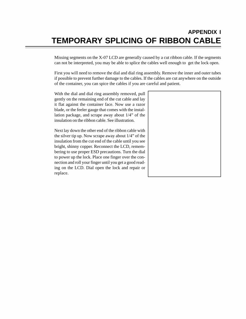
With the dial and dial ring assembly removed, pullgently on the remaining end of the cut cable and layit flat against the container face. Now use a razorblade, or the feeler gauge that comes with the instal-lation package, and scrape away about 1/4” of theinsulation on the ribbon cable. See illustration.
Next lay down the other end of the ribbon cable withthe silver tip up. Now scrape away about 1/4” of theinsulation from the cut end of the cable until you seebright, shinny copper. Reconnect the LCD, remem-bering to use proper ESD precautions. Turn the dialto power up the lock. Place one finger over the con-nection and roll your finger until you get a good read-ing on the LCD. Dial open the lock and repair orreplace.
APPENDIX J
ILLUSTRATIONS
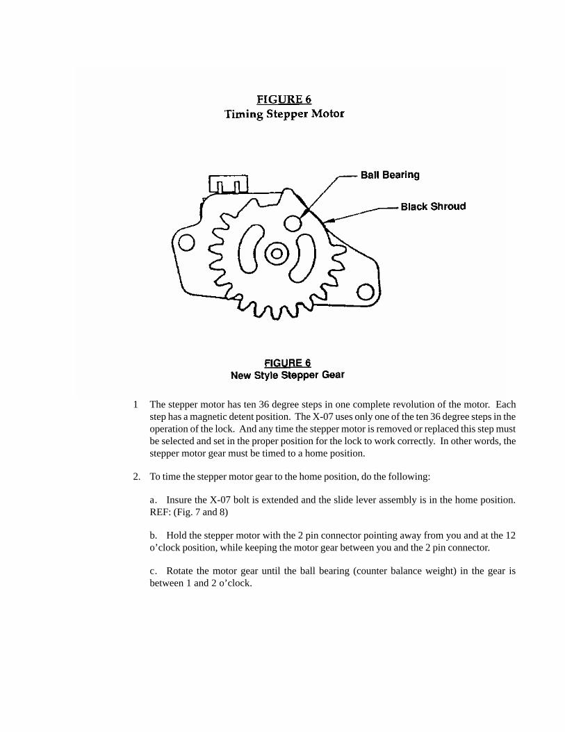
1 The stepper motor has ten 36 degree steps in one complete revolution of the motor. Eachstep has a magnetic detent position. The X-07 uses only one of the ten 36 degree steps in theoperation of the lock. And any time the stepper motor is removed or replaced this step mustbe selected and set in the proper position for the lock to work correctly. In other words, thestepper motor gear must be timed to a home position.
2. To time the stepper motor gear to the home position, do the following:
a. Insure the X-07 bolt is extended and the slide lever assembly is in the home position.REF: (Fig. 7 and 8)
b. Hold the stepper motor with the 2 pin connector pointing away from you and at the 12o’clock position, while keeping the motor gear between you and the 2 pin connector.
c. Rotate the motor gear until the ball bearing (counter balance weight) in the gear isbetween 1 and 2 o’clock.
X
www.mas-hamilton.com805-D Newtown Circle, Lexington, KY 40511
Phone (888) 950-4715 or (859) 253-4744 FAX (859) 281-5766Technical Support (800) 950-4744
Notice: The information in this manual is subject to change without noticeand does not represent a commitment on the part of Mas-HamiltonGroup (MHG). MHG shall not be liable for technical errors or omis-sions contained herein; not for incidental or consequential damagesresulting from the furnishing, performance or use of this material.
© 1997, 1998, 2000 Mas-Hamilton Group®
All rights reserved
Document Number 041.018 Rev. B 01/98Converted to Acrobat 08/00