x / accusens charge series
TRANSCRIPT
1
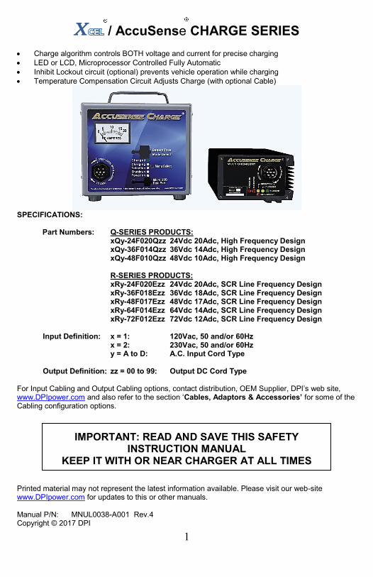
X / AccuSense CHARGE SERIES
Charge algorithm controls BOTH voltage and current for precise charging
LED or LCD, Microprocessor Controlled Fully Automatic
Inhibit Lockout circuit (optional) prevents vehicle operation while charging
Temperature Compensation Circuit Adjusts Charge (with optional Cable)
SPECIFICATIONS: Part Numbers: Q-SERIES PRODUCTS: xQy-24F020Qzz 24Vdc 20Adc, High Frequency Design xQy-36F014Qzz 36Vdc 14Adc, High Frequency Design xQy-48F010Qzz 48Vdc 10Adc, High Frequency Design R-SERIES PRODUCTS: xRy-24F020Ezz 24Vdc 20Adc, SCR Line Frequency Design xRy-36F018Ezz 36Vdc 18Adc, SCR Line Frequency Design xRy-48F017Ezz 48Vdc 17Adc, SCR Line Frequency Design xRy-64F014Ezz 64Vdc 14Adc, SCR Line Frequency Design xRy-72F012Ezz 72Vdc 12Adc, SCR Line Frequency Design Input Definition: x = 1: 120Vac, 50 and/or 60Hz x = 2: 230Vac, 50 and/or 60Hz y = A to D: A.C. Input Cord Type Output Definition: zz = 00 to 99: Output DC Cord Type For Input Cabling and Output Cabling options, contact distribution, OEM Supplier, DPI’s web site, www.DPIpower.com and also refer to the section ‘Cables, Adaptors & Accessories’ for some of the Cabling configuration options.
IMPORTANT: READ AND SAVE THIS SAFETY
INSTRUCTION MANUAL KEEP IT WITH OR NEAR CHARGER AT ALL TIMES
Printed material may not represent the latest information available. Please visit our web-site www.DPIpower.com for updates to this or other manuals. Manual P/N: MNUL0038-A001 Rev.4 Copyright © 2017 DPI

2
Table of Contents
Description Section Description Section User Safety Operations Guide 1 Output Connector Circuit 11 Personal Precautions 2 Temperature Compensation Option 12 A.C. And Utility Requirements 3 Vehicle Lockout Control Option 13 Safe Grounding Instructions 4 AC Convenience Port Option 14 Assembly And Preparing to Charge 5 Q-Series Schematic, Kits, Mounting 15 Charging A Rechargeable Battery 6 R-Series Schematic, Kits, Mounting 16 Multi-Stage Charge – LED 7 Cables, Adaptors & Accessories 17 Multi-Stage Charge – LCD 8 Accusense Charge Suite App. 18 Error Code Description 9 Warranty 19 Troubleshoot / Technical Guide 10
Throughout this manual, look for this symbol. It means ‘BE ALERT – YOUR SAFETY IS INVOLVED’. If you do not follow these safety instructions, personal injury or property damage may occur.
1. USER SAFETY OPERATIONS GUIDE
WARNING – RISK OF EXPLOSIVE GASES. WORKING WITH RECHARGEABLE BATTERY(s) IS DANGEROUS. EXPLOSIVE GASES DEVELOP DURING NORMAL BATTERY OPERATION. READ THIS MANUAL EACH TIME AND MAKE CERTAIN YOU FULLY UNDERSTAND IT AND FOLLOW THE SAFETY AND OPERATING INSTRUCTIONS AT ALL TIMES.
To reduce risk of battery explosion, follow all safety instructions below and those published by the battery manufacturer. Review cautionary markings on vehicle or equipment containing the battery.
Use of an attachment not recommended or sold by the battery charger manufacturer may result in a risk of fire, electric shock or injury to persons.
Do not operate this charger if it has received a sharp blow, was dropped or otherwise damaged in any manner. Refer to a qualified service agent.
Charger contains no serviceable parts. If it fails during its warranty period, contact your dealer OEM Supplier or visit DPI’s website, www.DPIpower.com for information concerning how to obtain a warranty replacement.
To reduce risk of electric shock, unplug charger from AC outlet before attempting any maintenance or cleaning.
For external cleaning use a clean damp towel.
Have your distributor, dealer or other qualified service agent, repair or replace worn or damaged parts immediately. Repairs should not be attempted by people who are not qualified.
Whenever removing AC Plug from the receptacle, pull from the Plug Body; not from the cord.
Do not operate the charger if it is malfunctioning. Personal injury or property damage could result.
3
2. Personal Precautions While Working With Batteries Have someone within range of your voice to come to your aid if needed.
Have plenty of fresh water and soap nearby in case battery acid contacts your skin, clothing or eyes. Wear eye and clothing protection and avoid touching eyes.
If battery acid contacts skin or clothing, wash immediately with soap and water.
If acid enters eye, immediately flush eye with running cold water for at least 10 minutes. Get medical attention immediately.
NEVER smoke or allow a spark or flame in vicinity of battery.
Be extra cautious not to drop a metal tool onto battery. It might spark or short circuit battery or other electrical part that may cause an explosion.
Remove personal metal items such as rings, necklaces, watches, etc. Batteries can produce a short-circuit current high enough to weld such items causing a severe burn.
NEVER charge a frozen battery. Thaw it out for safer and more efficient charging.
WARNING: CHARGERS CAN IGNITE FLAMMABLE MATERIALS AND VAPORS. DO NOT USE NEAR FUELS, GRAIN DUST, SOLVENTS, OR OTHER FLAMMABLES. TO REDUCE THE RISK OF AN ELECTRIC SHOCK, KEEP THE CHARGER DRY. DO NOT EXPOSE IT TO RAIN OR WATER.
3. A.C. AND UTILITY REQUIREMENTS
The use of an improper extension cord could result in a risk of a fire or electric shock. If an extension cord must be used, it must be UL and/or CSA approved. Locate all cords so that they will not be stepped on, tripped over or otherwise subjected to damage or stress. Extension cord must be properly wired and in good electrical condition, and large enough for the AC rating of charger as specified in this TABLE:
RECOMMENDED MINIMUM AWG SIZE FOR
EXTENSION CORDS FOR BATTERY CHARGERS Length of cord (feet): 25 50 100 150 AWG size of cord: 16 16 14 12
Refer to the Product ID Label affixed to the product and identify the input requirements such as ‘120Vac, 60Hz, 10Amps’. Ensure that the product will be connected to a matching utility power rating. For example; if product is rated at 60Hz, do not connect to a 50Hz utility.
The rating of the input A.C. Cord, if replaced by a certified technician, must not be less than 16Ga, 300V for 100Vac or 120Vac utilities and not less than 18Ga, 300V for 230Vac or 240Vac utility power. Cord must be hard usage SJT type or better, UL/CSA approved. The cable end connecting to charger must be an approved IEC 60320 power connector.

4
Do not connect product to AC receptacles that share power with any other moderate to heavy loads such as air conditioners, motors and other common appliances. Most appliances turn on/off at random and cause power surges and power droops that can severely affect the product connected to that same power circuit.
Inspect AC Receptacles for general wear, including loose or hanging receptacles and be very aware of potentially worn contacts. If any heat is felt in and around the receptacle while the charger is operating, this is an immediate indication of danger caused by a worn receptacle.
4. SAFE GROUNDING INSTRUCTIONS Do not remove Ground Pin from charger’s A.C. Plug, or connect to utility
power via an adaptor that bypasses the product’s ground pin connection. The product must be grounded at all times when connected to utility power.
This battery charger must be grounded to reduce the risk of electric shock. This charger is equipped with an AC cord set having an equipment-grounding conductor. This AC cord set must be connected to an appropriate receptacle that is properly installed and grounded in accordance with the National Electrical Code and all local codes and ordinances.
WARNING: IMPROPER CONNECTION OF THE EQUIPMENT-GROUNDING
CONDUCTOR CAN RESULT IN A RISK OF AN ELECTRIC SHOCK.
The conductor with insulation having an outer surface that is green, with or without yellow stripe(s), is the equipment-grounding conductor. If repair or replacement of the charger’s AC cord set is necessary, refer to a qualified service agent, and do not connect the equipment-grounding connector to a live terminal.
5. ASSEMBLY AND PREPARING TO CHARGE
WARNING: The instructions printed on the charger are for daily reference. For your own protection, when using ANY type of charger, always ensure that the batteries in your Battery Pack ARE ALL at the same state of charge, same condition, same size, and same rating. DO NOT MIX DIFFERING BATTERY SIZES, BATTERY TYPES OR OLD BATTERIES WITH NEW. Never use charger for any purpose contrary to its intended purpose of charging rechargeable batteries in accordance with ALL instructions printed in this manual.
IMPORTANT: Attach Output DC Cable to Charger BEFORE
Connecting to Equipment or Vehicle. Insert Cable Connector into Charger Output Connector and Rotate Lock until the Lock CLICKS into position and the wings on the Rotate Lock line up with the Lock Mark position on the front product Label.
5
Be sure area around battery is well ventilated while battery is being charged. Gas can be forcefully blown away using a non-metallic material like cardboard.
Inspect the receptacle found on the Equipment or Vehicle into which the charger output cable connector is expected to mate into: o The receptacle must not be worn in any way. Also, carefully inspect
receptacle contacts for wearing, burn or pitting marks.
o The receptacle contacts must be clean and free of any dirt, grime, grease, liquids, or other contamination.
o High power currents flow across the contacts between Charger Plug and
Vehicle Receptacle and can be a source of high heat when mating contact surfaces are worn or dirty. Replace receptacle or charger plug, or both when worn. It is also highly suggested to periodically replace the plug and receptacle every three years, but subjective to use, as is the case with all plugs and receptacles on all appliances.
Inspect the Equipment or Vehicle Cabling periodically – (at least monthly), for loose or worn wires, connectors, terminals and ensure that fuse safety devices have been installed by the Equipment or Vehicle manufacturer. Start at the receptacle and inspect each wire and joint connecting the battery, including inter-battery connections.
Follow the wire connection from the Equipment or Vehicle’s receptacle down to the first battery on both the positive and negative conductors. On one of those conductors, an in-line fuse or a fuse-box fitted with a fusing protection device must be installed – preferably within 6 inches (150mm) of the battery post on the first battery. If fusing is not found, install fuse protection prior to using charger with that equipment or vehicle.
If the OEM Equipment or Vehicle was not properly protected with fusing, as may be the case with much older equipment or vehicles, DPI has made available a ‘Battery Terminal to Receptacle Wire/Circuit Fuse Protection Kit’, such as KITS0009’ which is easy to install. Visit www.DPIpower.com.
The charger is factory preset to charge in MODE-1, unless supplied with an OEM’s equipment or vehicle – in which case, the MODE will be set to that mode defined by the OEM Equipment Specification. If changing battery type, verify and re-establish the Charger MODE settings.
If charger was purchased ‘used’ or with used equipment – IDENTIFY BATTERY INSTALLED IN THE EQUPMENT AND VERIFY THAT THE MODE IN WHICH THE CHARGER IS SET, IS APPROPRIATELY SELECTED FOR THAT BATTERY. This will ensure that an ‘inventory-stocked charger’ at the Dealer’s
location was not mismatched with the battery installed on the equipment or vehicle.

6
The charger has 32 Charge Algorithm Modes available. Each mode is set to charge a particular Battery Pack AND MUST BE SET CORRECTLY IN ACCORDANCE WITH THE FOLLOWING TABLE:
‘CHARGE MODE SETTING TABLE’:
MODE – Switch Setting: 0 = Switch Up ( or left if vertically orientated ) 1 = Switch Down ( or right if vertically orientated ) Switch Setting is numbered left to right or up/down ‘1’ to ‘5’ Mode Battery Name Type AH Range Absorption Switch Setting (Numbered) Voltage* 1 2 3 4 5 01 Crown CR-225 Flooded 200-250AH 2.380V 0 0 0 0 0 02 Exide GC-135 Flooded 200-250AH 2.400V 0 0 0 0 1 03 JCI 6V-GC2 Energizer Flooded 210-260AH 2.450V 0 0 0 1 0 04 Trojan T105 Flooded 200-250AH 2.400V 0 0 0 1 1 05 Trojan T1275 Flooded 130-170AH 2.400V 0 0 1 0 0 06 Trojan L16G-AC Flooded 355-425AH 2.400V 0 0 1 0 1 07 USBattery US1800 Flooded 190-235AH 2.450V 0 0 1 1 0 08 USBattery US2200 Flooded 205-260AH 2.450V 0 0 1 1 1 09 Full River DC220-6 AGM 195-245AH 2.450V 0 1 0 0 0 10 Full River DC335-6 AGM 305-365AH 2.450V 0 1 0 0 1 11 GNB M83CHP06V27 AGM 170-220AH 2.330V 0 1 0 1 0 12 Trojan T105 Reliant AGM 210-230AH 2.450V 0 1 0 1 1 13 USBattery US2224 AGM 200-250AH 2.400V 0 1 1 0 0 14 Trojan 6V-GEL GEL 165-215AH 2.333V 0 1 1 0 1 15 PsZ-Cell – Lead Acid Flooded 075-125AH 2.400V 0 1 1 1 0 16 PsZ-Cell – Lead Acid Flooded 125-175AH 2.400V 0 1 1 1 1 17 PsZ-Cell – Lead Acid Flooded 200-250AH 2.400V 1 0 0 0 0 18 PsZ-Cell – Lead Acid Flooded 300-350AH 2.400V 1 0 0 0 1 19 PsZ-Cell – Lead Acid AGM 075-125AH 2.450V 1 0 0 1 0 20 PsZ-Cell – Lead Acid AGM 125-175AH 2.450V 1 0 0 1 1 21 PsZ-Cell – Lead Acid AGM 200-250AH 2.450V 1 0 1 0 0 22 PsZ-Cell – Lead Acid AGM 300-350AH 2.450V 1 0 1 0 1 23 General – GEL GEL 075-125AH 2.333V 1 0 1 1 0 24 Enersys 12XFC82 Pure Lead 075-125AH 2.450V 1 0 1 1 1 25 General – Pure Lead Pure Lead 200-250AH 2.433V 1 1 0 0 0 26 General – Pure Lead Pure Lead 300-375AH 2.433V 1 1 0 0 1 27 Optima OPT-D31M Spiral 050-100AH 2.450V 1 1 0 1 0 28 General – Spiral Lead Spiral 130-170AH 2.450V 1 1 0 1 1 29 Sony LiFePO4 Cell Li+ 055-065AH 4.172V 1 1 1 0 0 30 Sony LiFePO4 Cell Li+ 190-210AH 4.172V 1 1 1 0 1 31 BMZ LiFePO4 Cell Li+ 160-175AH 4.175V 1 1 1 1 0 32 Empty/User Configured User N/A 1 1 1 1 1
*NOTE: The Absorption Value is listed as Volts Per Cell and is one of the most important parameters pertaining to that charge algorithm. Different battery packs have differing number of cells – multiply the number of cells times the ‘Volts-Per-Cell’ value to obtain the voltage the charger will regulate during the Absorption Charge Stage. For example; using MODE-2 ‘Absorption Voltage value of 2.400V/cell’ from the table above:
12V Battery Pack = 6 Cells Absorption = 14.40Vdc 24V Battery Pack = 12 Cells Absorption = 28.80Vdc 36V Battery Pack = 18 Cells Absorption = 43.20Vdc 48V Battery Pack = 24 Cells Absorption = 57.60Vdc 72V Battery Pack = 36 Cells Absorption = 86.40Vdc
For Lithium Battery MODES and using MODE-31 as the example: 12V Battery Pack = 3 Cells Absorption = 12.52Vdc 24V Battery Pack = 7 Cells Absorption = 29.22Vdc 36V Battery Pack = 11 Cells Absorption = 45.92Vdc 48V Battery Pack = 14 Cells Absorption = 58.44Vdc 72V Battery Pack = 21 Cells Absorption = 87.66Vdc

7
Many rechargeable batteries share an exact or very similar profile to one of the battery types listed above. Contact Factory to ask for MODE setting for a battery type not listed, or visit www.DPIpower.com and download DPI’s document: ‘DPI Battery MODE Setting Algorithm Match-Up’.
6. CHARGING A RECHARGEABLE BATTERY
An LED Display is assumed to be used. For products using an LCD (Liquid Crystal Display) Display, the information below is displayed in readable format – refer to the section titled ‘LCD Display Menu Formats’ for a complete description of how the LED information is translated and displayed on the LCD.
For 4 consecutive seconds, upon connection to AC Power, the Front Panel LEDs will flash a pattern to annunciate the mode setting as Described in the following table where ‘0’ = Off, and ‘1’ indicates LED Flashing:
‘LED CHARGE MODE INDICATOR TABLE’:
MODE LEDs Left to Right MODE LEDs Left to Right SET 1 2 3 4 5 SET 1 2 3 4 5 01 0 0 0 0 1 17 1 0 0 0 1 02 0 0 0 1 0 18 1 0 0 1 0 03 0 0 0 1 1 19 1 0 0 1 1 04 0 0 1 0 0 20 1 0 1 0 0 05 0 0 1 0 1 21 1 0 1 0 1 06 0 0 1 1 0 22 1 0 1 1 0 07 0 0 1 1 1 23 1 0 1 1 1 08 0 1 0 0 0 24 1 1 0 0 0 09 0 1 0 0 1 25 1 1 0 0 1 10 0 1 0 1 0 26 1 1 0 1 0 11 0 1 0 1 1 27 1 1 0 1 1 12 0 1 1 0 0 28 1 1 1 0 0 13 0 1 1 0 1 29 1 1 1 0 1 14 0 1 1 1 0 30 1 1 1 1 0 15 0 1 1 1 1 31 1 1 1 1 1 16 1 0 0 0 0 32 1 1 1 1 1 (Fast-Flash) Note: For Vertical oriented LED Display, ‘Left’ is equivalent to ‘Bottom’ LED
MODE-31 is empty – selection of an empty MODE will produce an Empty Mode Error. A Slow Flash rate is used to annunciate Modes 1 to 31. Mode-32 uses a Fast-Flash rate. NOTE: If the charger has been subjected to Field Reprogramming by the user, during
the first time charger is used, startup time can take up to 10 minutes. The LEDs will not flash and the charger will appear to be ‘frozen’. Do not unplug charger because it is rebuilding its internal Database – refer to the section titled ‘Accusense Charge Suite Application’ for further details.
Multi-Stage Charge Algorithms
o There are up to 8 charging Stages! Depending on the MODE selected, these stages are already preset and implementation of each stage will vary from one MODE to the next, dependent on the type of battery intended to be charged. These charge stages ‘typically’ include:

8
o PRE-QUALIFICATION-TEST Charge Stage:
Tests battery for sulphation by applying a low level charge current and
analyzes voltage and current values and rates of change to determine if the battery is ready to transition to the next high power Bulk Charge Stage.
If a Battery Temperature Cable is installed, then minimum and maximum temperature automatically become part of the analysis.
o BULK Charge Stage (also known as ‘Constant-Current’):
High Power charge, charges at a constant current or constant power rate to deliver the ‘bulk’ of the charge needed
Some algorithms employ a 2-step Bulk Charge rate where a timed 10 to 30 minute period of a higher current may be measured. This two-step process helps to break down sulphates quicker.
Upon completion of this stage, approximately 80% of total charge is delivered to the battery
o ABSORPTION Charge Stage (also known as ‘Constant-Voltage’):
Charger charges at a constant voltage level to provide adequate time for the battery plates to ‘absorb’ the energy delivered.
Charge Amperage decreases as the energy is being absorbed into the plates.
Termination of this stage occurs when the charge current has decreased down to a targeted value which is dependent on many factors such as size, type, age, and chemistry of battery.
Upon completion of this stage, approximately 95% of total charge is delivered to the battery
o TOP-OFF Charge Stage (also known as ‘Finish’):
Charger charges at either a constant voltage, or constant current, or a combination of constant-current / constant voltage to ‘Top-Off’ the charge in a battery.
This stage employs timing based on ‘timers’ measured and recorded during previous charge stages, in combination with dv/dt and/or di/dt, and/or dT/dt, and/or, maximum voltage and temperatures (if Battery Temperature Sensor installed), to terminate.
Variations in this charge stage are highly dependent on the battery Charge MODE selected. Flooded Lead Acid batteries are typically aggressively charged to high voltage levels to force internal gassing which helps to mix the electrolyte. AGM (Absorbed Glass Mat) batteries differ in that this stage limits upper voltage regulation levels which helps prevent drying out the Absorbed Glass Mat.
Upon completion of this stage, approximately 100% of total charge is delivered to the battery
o EQUALIZATION Charge Stage:
As batteries in a battery pack charge and discharge over many cycles, cells may become unbalanced. Cell unbalancing becomes more common as batteries age.

9
Charger charges at either a constant voltage, or constant current, or a combination of constant-current / constant voltage to ‘Equalize’ Battery Cells in the battery.
This stage employs Timers in combination with dv/dt and/or di/dt, and/or dT/dt, and/or, maximum voltage and temperatures (if Battery Temperature Sensor installed), to terminate.
Even if this stage is activated in a charge MODE, it is not applied during every charge cycle. For lithium and GEL batteries, Equalization is not applied and cannot be manually selected.
Manual (intentional) selection of this charge stage, by the user, can be selected by depressing and holding depressed the ‘Menu Select Button’ for 10 seconds WHILE A.C. Power is applied. If the Menu Select Button is again depressed and held depressed for 10 seconds, this stage will toggle off.
The charge cycle, in which this additional Equalization Charge Stage will inject itself into, will be announced by either flashing the Red Power-On LED or flashing the LCD Backlight, continually throughout the ENTIRE charge cycle. The flash will stop upon entry into the Float/Maintenance Standby Stage
o FLOAT/MAINTENANCE STANDBY Charge Stage:
The entry into this stage typically signifies that the battery is FULLY charged and has a Green LED ‘Charged’ indicator associated with it. On an LCD display, the status will display as ‘FLT’.
No further charging action occurs. However, all batteries, regardless of chemistry, self-discharge at a rate that is proportional to ambient temperature meaning that if a battery sits on a table completely disconnected from all loads, it will self discharge over many months.
This charge stage, depending on the MODE selected will either: Regulate at a low voltage level to supply a ‘trickle current’ to
‘MAINTAIN’ battery at full charge (prevent self discharge), or Disconnect itself from A.C. Power by disabling the internal relay,
and allow the battery voltage to ‘FLOAT’ for 45 days, at which time, the charger will automatically re-initiate, an new charge cycle and automatically reconnect to A.C. Power, or
Re-start charging if the battery voltage decays below a trigger voltage level
If the charger is fitted with an internal A.C. Connect/Disconnect relay, typically, the output is allowed to ‘FLOAT’ and not regulated, which prevents the consumption of utility provided power.
During this stage, regardless of the use of an A.C. Relay, the microprocessor continues to monitor the battery and passage of time while in this ‘STANDBY’ stage.
The charger may be left connected to battery with the A.C. Power Removed. The amount of drain from the battery is very minimal.
Common Traits Applied to All Charge Stages:
Each Charge Stage employs the use of a ‘Safety Timer’ to time out and end that stage if the stage process took too long without achieving the desired targeted results.
Upon Safety Timer time out, a decision is automatically established to transition to the next stage, or advance immediately to the final stage –

10
Float/Maintenance Standby Stage, or terminate charge and display an Error Code.
Each Charge Stage employs dv/dt and/or di/dt and/or dT/dt signal analysis to monitor the progress of charging and factors into the termination of the stage.
If a Battery Temperature Sensor Cable is installed, the charger automatically detects its presence and will use it to adjust voltage and current charge rates during the deployment of the charge algorithm. For example, if charging in a cold temperature climate, the charger will increase the voltage level targets to compensate for the temperature. If the climate is hot, the regulation targets decrease automatically – this is also known as ‘Temperature Compensation’ and is typically adjusted to -2mV to -6 mV / cell /
oC.
Some Stages may not be applied. For example, Lithium Based Battery packs employ the use of Battery Management Systems and will not work if a Pre-Qualification-Test Stage is used. Therefore, when selecting a Lithium Charge Stage, Pre-Qualification Test Stage is automatically not employed.
7. MULTI-STAGE CHARGE (TYPICAL) WITH LED DISPLAY Under normal charge circumstances, the LEDs and Menu Switch operate as follows: Power On (Red) Illuminates continuously when AC power present. Refer to
the section ‘TROUBLESHOOTING’ if FLASHING, but not when flashing during a Charge Cycle that includes Equalization Charge Stage.
Shutdown (Red) Illuminates typically when used only during Error Decode
Mode. Refer to ‘TROUBLESHOOTING’ if FLASHING.
Detection (Red) Illuminates when battery not connected (but, while powered from A.C.), or for a brief period immediately following an A.C. Connection. Refer to ‘TROUBLESHOOTING’ if FLASHING.
Charging (Yellow) Charge Status Indicator – FLASHES or illuminates during
the Multi-Stage Charge Process. Charged (Green) Illuminates during the Top-Off Stage and Float/Maintenance
Stages of the Multi-Stage Charge Process. When FLASHING in conjunction with a continuously illuminated Power On Red LED it is signifying an ALERT. Refer to the section titled Error Code Description for ALERT definitions.
Menu Select Button Depressing and holding depressed, this button for 10
seconds at power up, forces charger to insert the Equalization Stage into the charge algorithm regiment IF and only IF, that charge MODE selected, would allow it. After power up, and if switch is again held depressed for 10 seconds, the Equalization Charge Stage is toggled to OFF (de-asserted from the charge algorithm Regiment).
The following description assumes the charger is set in MODE-1 to charge a typical Flooded Lead Acid Battery.

11
MODE-1 is annunciated for 4-seconds after A.C. Power applied, where the Right Most LED flashes. Refer to the LED CHARGE MODE INDICATOR TABLE’ and CHARGE MODE SETTING TABLE.
o ‘Power On’ LED and Detection LED will illuminate to indicate that AC power is applied AND battery is in the process of being detected.
o If the Red ‘Power On’ LED Flashes, it is indicating that the pending Charge Cycle will apply a special charge called ‘Equalization Charge’. Refer to Equalization Charge Cycle section for description of stage.
STAGE ONE – PRE-QUALIFICATION TEST
o Yellow (Charging) LED flashes slowly (once per second) to test battery. Charging stops if faults such as connection of 24v charger to a 36V battery pack or safety timers timed out, etc. Refer to ‘Troubleshooting Guide’ if an Error Code was displayed.
o Duration of this stage is dependent on condition of battery – approximately 10 seconds under average circumstances, but if your battery pack was allowed to severely discharge to less than 1.75Vdc per cell (example – 21v for a 24v battery), then the charger may take several hours of slow charging to try to slowly bring the battery up to above 1.75Vdc per cell.
STAGE TWO – BULK CHARGE (Constant Current)
o Yellow (Charging) LED illuminates continuously indicating charging at full rated output. While charging, voltage is monitored for the occurrence of the next charging stage.
STAGE THREE – ABSORPTION CHARGE (Constant Voltage)
o Yellow (Charging) LED illuminated continuously. The charger now regulates at Absorption Voltage Level while monitoring charge current.
o Once Charge Current has decreased to a sufficiently low level, this stage exits to the next stage.
o The Battery Pack has achieved approximately 95% State of Charge.
STAGE FOUR – TOP OFF CHARGE STAGE
o Both Green (Charged) and Yellow (Charging) LEDs illuminate. o Replenishing last 5-10% of battery capacity. Charging at a low Constant
Current rate, this stage monitors for time and dv/dt to terminate. o The Battery Pack has achieved approximately 95% State of Charge. o NOTE: If using a Charger MODE set to charge a Flooded USBattery only,
this stage may take up to 4 hours to complete.
STAGE FIVE – EQUALIZATION CHARGE CYCLE
o This is a special charge condition that is selectively applied and is not typically applied to every battery, nor with every charge cycle. If it is applied, the next stage becomes Stage Six. If not applied, then the next stage becomes Stage Five.
o The Red ‘Power-On’ LED will flash during the entire cycle in which Equalization Charge Stage has been invoked, and the flashing will cease when charge has completed.
12
o Equalization Charge is an additional charge stage injected here and is invoked via the following methods: A MODE containing a flooded USBattery battery, such as battery type
US1800, and Every 15
th charge cycle is started, and/or
If the A.C. Cord is plugged/unplugged 15 times, and/or
The ‘Menu Select’ Button is held depressed for 10seconds when A.C. power is applied
o While in this specific Charge Stage, the Yellow/Green LEDs will flash alternately.
o This Charge Stage locks in for a period of 2hrs to 4hrs and can terminate at any time after the minimum 2hr period when a series of dv/dt measurement records have been satisfied.
STAGE FIVE or SIX – FLOAT/MAINTENANCE (STANDBY)
o Green (Charged) LED illuminates. Battery is fully charged and no further ‘charging’ action is occurring. Charger is now in standby and monitoring the battery and passage of time. Charger may now also be left connected to battery, indefinitely.
o If the Green LED flashes, it is signaling an abrupt change in the previous charge cycle (but not an error) and may require additional attention according to the flash rate: Slow Flash: Charge cycle ended via peak voltage detection in the Top-
Off Charge stage. Medium Flash: Charge cycle ended via peak voltage detection in the
Equalization Charge Stage. Fast Flash: Charge cycle ended via Maximum Safety Timer time-out. Modified Flash Pattern – Flash-Flash-Flash-OFF: When the Battery
Temperature Cable is connected and a maximum battery temperature was reached, charging was terminated early.
o If any of these flashing patterns occurred, check all of the equipment or vehicle’s inter-wire connections from receptacle to batteries, including inter-battery wiring for loose and/or dirty or worn or burned connections. Also, check each battery for possible replacement of that battery and battery pack.
STAGE SIX or SEVEN – RECYCLE CHARGE STAGE
o While in Standby Mode (Stage-5 or 6: Float/Maintenance) and if a substantial load were to be applied, charger will reset; thereby, automatically initiating a new charge cycle routine and restoring battery to full capacity.
o If while charging, the charger finds an abnormal charge condition, it will attempt to shut down and indicate the ‘Condition’ by flashing any one of the LEDs. Refer to the ‘Troubleshooting’ section for a description of the Charge Error Condition.

13
8. MULTI-STAGE CHARGE (TYPICAL) WITH LCD DISPLAY Use of an LCD Display, does not affect nor alter the charge process in any way.
It only converts messages from what is otherwise a blinking LED into readable characters. Therefore, refer to the previous section for a description of a typical charge stage and reference the displayed LCD messages, below.
Menu Select Button:
o Depressing and holding depressed this button for 10 seconds at power up,
forces charger to insert the Equalization Stage into the charge algorithm regiment IF and only IF, that charge MODE selected, would allow it. After power up, and if switch is again held depressed for 10 seconds, the Equalization Charge Stage is toggled to OFF (de-asserted from the charge algorithm Regiment).
o If depressed for at least 1 second, but released less than 10 seconds, the menu display toggles up to the next incremental menu and stays active for approximately 30seconds before reverting back to the default menu in effect previously. You will know when the 1second period has been reached because the LCD Backlight will ‘Blink’.
Five Menus are made available and are selectable via the Menu Select Button: Annunciation (Start Up) Menu Charge Status And Output Display Charge Status And Input Display Error Code Display Charge Status and Temperature Display
ANNUNCIATION (START UP) MENU
o Display shows (assume 24V Battery Charger):
MD: MODE is annunciated as ‘2’, MODE-2 TYPE: Type is annunciating the battery type as:
225 Ampere Hour Size Battery Pack Class is ‘02’ – Flooded Lead Acid Refer to Battery Type Class Table for full list
STAT: Status Identifier. Refer to Status Identifier Table This menu displays as the default menu during the initial 4 second
power-on start up
Battery Type Class Table: 01: AGM Lead Acid Battery 02: Flooded Lead Acid Battery 03: GEL Lead Acid Battery 04: Pure Lead – Lead Acid Battery 05: Spiral Lead Acid Battery 06: Uncategorized Lead Acid 07: Lithium Based Battery 08: Molten Salt Based Battery 09: Nickel Based Battery 10: Organic Based Battery 11: Potassium Based Battery 12: Silicon Based Battery 13: Silver Based Battery 14: Sodium Based Battery
o Call factory for additionally available Algorithms developed for rechargeable
chemistries that can be downloaded into a spare MODE. Also, refer to the ‘Accusense Charge Suite Application’ section for further details.
MD ---TYPE--- STAT
02 0225Ah02 --HF--

14
CHARGE STATUS AND OUTPUT DISPLAY MENU o Display shows (assume 24V Battery Charger):
STAT: Status Identifier. Refer to Status Identifier Table -Vdc-: Battery Voltage measured on the output leads -Adc-: Charge Current Output measured in amps This menu displays as the default menu during charging. The Status
displays the current charge stage in effect – for example, cCCT is Bulk Constant Current Charge Stage.
CHARGE STATUS AND INPUT DISPLAY MENU
o Display shows (assume 24V Battery Charger):
STAT: Status Identifier. Refer to Status Identifier Table -Vdc-: Battery Voltage measured on the output leads -Adc-: Charge Current Output measured in amps This menu does not display as a default. It must be selected. Additionally, only the Vac is displayed and is for reference use by Tech
Support, only – the value is not indicative of actual utility AC power
ERROR CODE DISPLAY MENU o Display shows (assume 24V Battery Charger):
ERROR Code: Refer to LCD Error Code Table Second Line: Brief Description of Error – Refer to Troubleshooting This menu displays as the default menu after an Error Condition has
been reported. Additionally, the backlight flashes in an on-on-on-off pattern, repeatedly
CHARGE STATUS AND TEMPERATURE DISPLAY MENU
o Display shows (assume 24V Battery Charger):
STAT: Status Identifier. Refer to Status Identifier Table Int*C: Internal Charger Temperature in Celsius Ext*C: External Battery Temperature in Celsius This menu does not display as a default. It must be selected.
STAT ---Vdc--- ---Adc---
cCCT 27.4 20.1
STAT ---Vac--- ---Aac---
cCCT 127.4 N/A
ERROR_Code -> 01
Battery OverVolt
STAT Int*C Ext*C
cCCT 37 25

15
Status Identifier Table: NoBt: No battery detected. AC Is applied but output does not
detect a battery or battery could be severely discharged down beyond point of not being detected.
StBy: Battery has been detected, but AC. Power has not been detected – therefore sit in Standby Mode
Paus: Pause – Charging is suspended. Typically used with Over-The-Cloud Tech support where a command was sent to ‘pause’ operation
Acof MnTr Mode: AC is disconnected. Charger is in Monitor Mode – still connected to battery. This is an indicator that charging was completed, but then A.C. power was disconnected
cPQT Pre-Qualification-Test Charge Stage in effect cCCT Bulk Constant Current Charge Stage in effect cCPW Bulk Constant Power Charge Stage in effect cCVT Absorption Constant Voltage Charge Stage in effect cTOP Top-Off Finish Charge Stage in effect cEQU Equalization Charge Stage in effect cFIN Float/Maintenance Standby Stage in effect cFTR Float/Maintenance Standby Stage is in effect, but entered
with an advisory to check battery pack ERRr Charge Error detected – charging has stopped WAIT Waiting… 50Hz 50Hz Declaration – Product must use 50Hz utility Power 60Hz 60Hz Declaration – Product must use 50Hz utility Power _HF_ HF or Hybrid Product Design Declaration AC Drop Out AC has disconnected – Sit in Monitor Mode till AC restored.
This is an indicator that charging was terminated when A.C. Power was disconnected.
TSTg Testing product due to possibility of missing factory installed TestPassCode – the product is trying to reconfigure itself from internally saved configuration data.
9. ERROR CODE DESCRIPTION The number of Error Codes available exceeds a count of 32 (up to 64 are possible). With 5-LEDs available, only Code Numbers 1-31 can be displayed. Therefore, for LED based products, two Error-Code Annunciating Flash Patterns are employed which allows for the display of 1-31 using one pattern and 32 to 64 using an alternate pattern:
Flash in a pattern of ‘3-Fast-Flash, then off, 3-Fast-Flash etc. This Error Flash Pattern is annunciating an error in the range of 1 to 31.
Flash at a very fast rate. This Error Flash Pattern is annunciating an error in the range of 32 to 63.
LCD based models display the Error Code Number in readable format without limitation. The readable number is equivalent to the number displayed on an LED based product. During an Error Code Annunciation, the charge cycle has terminated its normal operation, prematurely. An abnormal charging condition was detected and charging stopped due to a Charge Error Condition. Refer to the following Charge Error Table for an extended
description of the failure or condition and its possible remedy. Error Code Values 1-31, which use the first flash pattern, are not highlighted. Error Code Values 32-64, which use the second flash pattern are highlighted in yellow. ‘ALERTS’ are highlighted in magenta.

16
CHARGE ERROR TABLE: Errors 1-64: Flashing LEDs
0=OFF, 1=Flashing, S=Solid Condition LED-1 LED-2 LED-3 LED-4 LED-5 Readable Battery Over Voltage 0 0 0 0 1 1 Battery Temperature Low 0 0 0 1 1 3 Battery Temperature High 0 0 1 0 0 4 Battery Pack Unbalanced –V 0 0 1 1 1 7 Battery Pack Unbalanced –A 0 1 0 0 0 8 Batt Is 100% Discharged 0 1 0 0 1 9 Batt Beyond Over Discharged! 0 1 0 1 0 10 Batt Emergency Under-Voltage 0 1 0 1 1 11 Batt Temperature Sensor Open 0 1 1 1 1 15 Batt Temperature Sensor Shorted 1 0 0 0 0 16 Batt Over-Temperature 1 0 0 0 1 17 Battery Storage Error 1 0 0 1 1 19 Battery Testing Error – Sulphated 1 0 1 0 0 20 Battery Testing Error – Discharged 1 0 1 0 1 21 Bulk Charge Safety Time Error 1 1 0 0 1 25 Absorption Safety Time Error 1 1 0 1 0 26 Excessive Safety Time Error 0 0 0 0 1 32 Mode Selected Not Valid – Empty 0 0 0 1 0 33 Product Not Operational! 0 0 0 1 1 34 Lockout (Inhibit) Enable Defective 0 0 1 0 0 35 Lockout (Inhibit) Disable Defective 0 0 1 0 0 36 Internal Over Temperature 1 0 0 0 1 48 Finish Stage Exit via High Voltage S 0 0 0 1 --- Equ. Stage Exit via High Voltage S 0 0 0 1 ---
Battery Over Voltage
o Charger’s Output DC Cable connection is possibly connected to a battery pack with voltage higher than the output rating of the charger.
Battery Temperature Low/High o If an external thermistor is connected in the application, the charger has detected
an attempt to use the battery out of its recommended temperature range… thaw the battery if cold or cease charging and allow battery to cool down before attempting to restart charge.
Battery Pack Unbalanced – V: o Caused by unbalanced battery condition and or excessive battery plate
sulphation during Bulk Constant Current Stage. Example: some batteries are at a much higher state of charge than others. This may require replacement of the batteries. Refer to the Equipment’s Operators manual for instructions on servicing the battery pack.
Battery Pack Unbalanced – A: o Caused by an unbalanced battery condition during Absorption Constant Voltage
Stage. Inspect each battery with a load tester as well as observe if any battery is ‘hotter’ to the touch than other batteries in the pack. The indication is that a cell(s) within the pack may have shorted, or experienced stratification of the electrolyte (over-charging due to incorrect MODE setting) and may require replacement of the batteries. Refer to the Equipment’s Operators manual for instructions on servicing the battery pack.
17
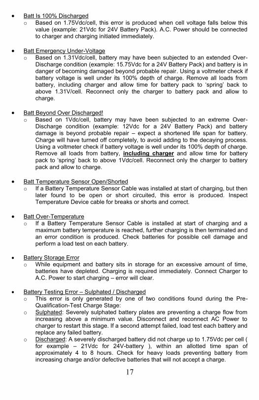
Batt Is 100% Discharged o Based on 1.75Vdc/cell, this error is produced when cell voltage falls below this
value (example: 21Vdc for 24V Battery Pack). A.C. Power should be connected to charger and charging initiated immediately.
Batt Emergency Under-Voltage o Based on 1.31Vdc/cell, battery may have been subjected to an extended Over-
Discharge condition (example: 15.75Vdc for a 24V Battery Pack) and battery is in danger of becoming damaged beyond probable repair. Using a voltmeter check if battery voltage is well under its 100% depth of charge. Remove all loads from battery, including charger and allow time for battery pack to ‘spring’ back to above 1.31V/cell. Reconnect only the charger to battery pack and allow to charge.
Batt Beyond Over Discharged! o Based on 1Vdc/cell, battery may have been subjected to an extreme Over-
Discharge condition (example: 12Vdc for a 24V Battery Pack) and battery damage is beyond probable repair – expect a shortened life span for battery. Charge will have turned off completely, to avoid adding to the decaying process. Using a voltmeter check if battery voltage is well under its 100% depth of charge. Remove all loads from battery, including charger and allow time for battery
pack to ‘spring’ back to above 1Vdc/cell. Reconnect only the charger to battery pack and allow to charge.
Batt Temperature Sensor Open/Shorted o If a Battery Temperature Sensor Cable was installed at start of charging, but then
later found to be open or short circuited, this error is produced. Inspect Temperature Device cable for breaks or shorts and correct.
Batt Over-Temperature o If a Battery Temperature Sensor Cable is installed at start of charging and a
maximum battery temperature is reached, further charging is then terminated and an error condition is produced. Check batteries for possible cell damage and perform a load test on each battery.
Battery Storage Error o While equipment and battery sits in storage for an excessive amount of time,
batteries have depleted. Charging is required immediately. Connect Charger to A.C. Power to start charging – error will clear.
Battery Testing Error – Sulphated / Discharged o This error is only generated by one of two conditions found during the Pre-
Qualification-Test Charge Stage: o Sulphated: Severely sulphated battery plates are preventing a charge flow from
increasing above a minimum value. Disconnect and reconnect AC Power to charger to restart this stage. If a second attempt failed, load test each battery and replace any failed battery.
o Discharged: A severely discharged battery did not charge up to 1.75Vdc per cell ( for example – 21Vdc for 24V-battery ), within an allotted time span of approximately 4 to 8 hours. Check for heavy loads preventing battery from increasing charge and/or defective batteries that will not accept a charge.
18
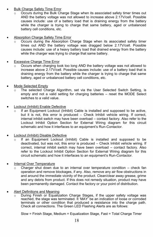
Bulk Charge Safety Time Error o Occurs during the Bulk Charge Stage when its associated safety timer times out
AND the battery voltage was not allowed to increase above 2.17V/cell. Possible causes include: use of a battery load that is draining energy from the battery while the charger is trying to charge that same battery, aged or unbalanced battery cell conditions, etc.
Absorption Charge Safety Time Error o Occurs during the Absorption Charge Stage when its associated safety timer
times out AND the battery voltage was dragged below 2.17V/cell. Possible causes include: use of a heavy battery load that drained energy from the battery while the charger was trying to charge that same battery.
Excessive Charge Time Error o Occurs when charging took too long AND the battery voltage was not allowed to
increase above 2.17V/cell. Possible causes include: use of a battery load that is draining energy from the battery while the charger is trying to charge that same battery, aged or unbalanced battery cell conditions, etc.
Mode Selected Empty o The selected Charge Algorithm, set via the User Selected Switch Setting, is
empty and not a valid setting for charging batteries – reset the MODE Select switches to a valid value.
Lockout (Inhibit) Enable Defective o If an Equipment Lockout (Inhibit) Cable is installed and supposed to be active,
but it is not, this error is produced – Check Inhibit vehicle wiring. If correct, internal inhibit switch may have been overload – contact factory. Also refer to the Lockout Inhibit Option Section for External Wiring diagram for this circuit schematic and how it interfaces to an equipment’s Run-Contactor.
Lockout (Inhibit) Disable Defective o If an Equipment Lockout (Inhibit) Cable is installed and supposed to be
deactivated, but was not, this error is produced – Check Inhibit vehicle wiring. If correct, internal inhibit switch may have been overload – contact factory. Also refer to the Lockout Inhibit Option Section for External Wiring diagram for this circuit schematic and how it interfaces to an equipment’s Run-Contactor.
Internal Over Temperature o Charger shut down due to an internal over temperature condition – check fan
operation and remove blockages, if any. Also, remove any air flow obstructions in and around the immediate vicinity of the product. Clean/clear away grease, grime and any debris from product. If this does not remedy situation, product may have been permanently damaged. Contact the factory or your point of distribution.
Alert Definitions and Meaning o During Finish or Equalization Charge Stages, if the upper safety voltage was
reached, the stage was terminated. It ‘MAY’ be an indication of loose or corroded terminals or other condition that produced a resistance into the charge path. Check all connections. The Green LED Flashing Alerts are as follows:
Slow = Finish Stage, Medium = Equalization Stage, Fast = Total Charge Timer

19
10. TROUBLESHOOTING AND TECHNICAL GUIDE To be able to troubleshoot safely and effectively, it is important to read this guide completely before beginning any tests.
WARNING: DO NOT DISASSEMBLE THE CHARGER. TAKE IT TO A QUALIFIED SERVICE AGENT WHEN SERVICE OR REPAIR IS REQUIRED. INCORRECT REASSEMBLY MAY RESULT IN A RISK OF ELECTRIC SHOCK OR FIRE. THE FOLLOWING PROCEDURES ARE INTENDED ONLY TO DETERMINE IF A MALFUNCTION MAY EXIST IN THE CHARGER.
DANGER: TO REDUCE THE RISK OF ELECTRIC SHOCK, ALWAYS DISCONNECT THE CHARGER’S AC CORD SET FROM AC POWER AND ITS DC CORD SET FROM BATTERIES BEFORE ATTEMPTING ANY MAINTENANCE OR CLEANING
LEDs Frozen (no activity) or Charger seems inoperable: o Battery may have been subjected to an Over-Discharge condition. Using a
voltmeter check if battery voltage is well under its 100% depth of discharge level defined as 1.75V per cell for lead acid batteries. For example, if a 24V lead acid battery measures well under 21V, then this condition may have occurred as a result of batteries left in lengthy storage without a trickle charge applied to it. Try removing the output leads from the battery pack (while A.C. Power is disconnected from the charger) and reconnecting the output leads.
Batteries Hot To the Touch – Charger Continues To Charge: o A hot battery(s) signifies cells that are:
Shorted due to material coalesced at the bottom of the cell and not able to break down and recombine back onto the battery plates, and/or
Stratification of the acid into layers where a denser acid layer is carrying most of the amperage
An overcharged cell due to other cells being unbalanced and at a much lower state of charge
o Possible corrections include Cease charging, operate vehicle to slightly discharge battery pack, and then
reapplying a charge Breaking apart the battery pack and load test each battery – replace
defective batteries Check Charger MODE settings and ensure it is properly set to the battery
selected to charge
Battery Run-Time Decreasing: o Refer to the Accusense Charge Suite Application section to review the many
tools available that aid supporting the analysis of historical charge/discharge data which may pinpoint possible remedies.
20
TECHNICAL NOTES
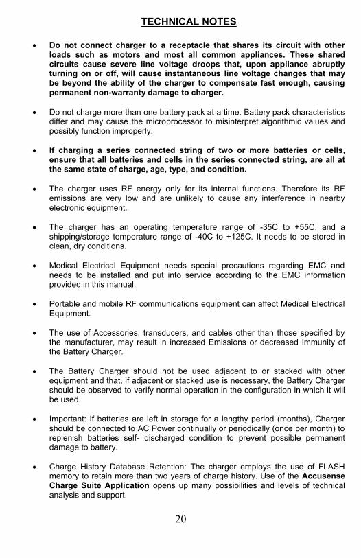
Do not connect charger to a receptacle that shares its circuit with other
loads such as motors and most all common appliances. These shared circuits cause severe line voltage droops that, upon appliance abruptly turning on or off, will cause instantaneous line voltage changes that may be beyond the ability of the charger to compensate fast enough, causing permanent non-warranty damage to charger.
Do not charge more than one battery pack at a time. Battery pack characteristics differ and may cause the microprocessor to misinterpret algorithmic values and possibly function improperly.
If charging a series connected string of two or more batteries or cells, ensure that all batteries and cells in the series connected string, are all at the same state of charge, age, type, and condition.
The charger uses RF energy only for its internal functions. Therefore its RF emissions are very low and are unlikely to cause any interference in nearby electronic equipment.
The charger has an operating temperature range of -35C to +55C, and a shipping/storage temperature range of -40C to +125C. It needs to be stored in clean, dry conditions.
Medical Electrical Equipment needs special precautions regarding EMC and needs to be installed and put into service according to the EMC information provided in this manual.
Portable and mobile RF communications equipment can affect Medical Electrical Equipment.
The use of Accessories, transducers, and cables other than those specified by the manufacturer, may result in increased Emissions or decreased Immunity of the Battery Charger.
The Battery Charger should not be used adjacent to or stacked with other equipment and that, if adjacent or stacked use is necessary, the Battery Charger should be observed to verify normal operation in the configuration in which it will be used.
Important: If batteries are left in storage for a lengthy period (months), Charger should be connected to AC Power continually or periodically (once per month) to replenish batteries self- discharged condition to prevent possible permanent damage to battery.
Charge History Database Retention: The charger employs the use of FLASH memory to retain more than two years of charge history. Use of the Accusense Charge Suite Application opens up many possibilities and levels of technical
analysis and support.

21
11. OUTPUT CONNECTOR CIRCUIT
7-CIRCUIT OUTPUT CONNECTOR FIGURE
The view of the connector is from the outside looking into the connector, with the output cable not installed
Each Pin installed constitutes ‘ONE’ Circuit
Not all circuits may be installed. But if they are installed, from one product to the next, the circuit functions remain consistent
The circuits are defined as follows: o PIN 1: Temperature Compensation Positive (+) o PIN 2: Temperature Compensation Negative (-) o PIN 3: Battery Charge Output Positive (+) o PIN 4: Vehicle Lockout (Inhibit) Positive (+) o PIN 5: Battery Charge Output Negative (-) o PIN 6: No Connection – Not Typically Installed o PIN 7: Vehicle Lockout (Inhibit) Negative (-)
12. TEMPERATURE COMPENSATION OPTION
Refer back to the section titled ‘Output Connector Circuit’ to locate the two circuit pins that connect a Temperature Compensation Cable
Temperature Compensation uses a temperature measuring device that is affixed to the battery pack and uses two conductors to connect back to the Output Connector located on the charger
Every DPI Gen-IV Charger contains a temperature compensation circuit, installed
If, at power up, or upon resetting, the charger looks to see if a Temperature Compensation Cable is installed and, depending on the Charge MODE:
o If not found installed, the charger will default to 25*C operation o If installed, charging set points will be automatically adjusted based on
battery temperature. This relationship is inversely proportional meaning that a reduction of voltages occurs as battery temperature increases
o If Temperature Compensation Cable was installed but then the cable experienced a break or a short in the cable, charging will cease and an error condition will be produced – refer to the Charge Error Table

22
Contact distribution, OEM Supplier, DPI’s web site, www.DPIpower.com or refer to the section ‘Cables, Adaptors & Accessories’ for Cabling configurations.
Alternately, your model may have already be supplied with this option
The end of the cable, where the Temperature Compensation device is located, must be connected to the most negative terminal of the battery pack
Adjustment rates are based on a typical -5mV per cell per degree Celsius, above or below 25*C. For example and using a 48V battery (24cells) and 35*C:
o .005V x 24cells x (35*C-25*C) = 1.2V o If, from the Charge MODE Setting Table, a mode was selected where
the battery regulated at 2.4V/cell (2.4V x 24cells = 57.6V total), then the temperature compensation would decrease that target voltage down to 56.4V (57.6V – 1.2V)
o Conversely, if the battery temperature was 15*C (10*C below 25*C), then the compensation would have increased the 57.6V target to 58.8V
When charging lead acid (and many other chemistry types) batteries during winter or cold climates, or operating equipment in ‘large Factory Freezer Applications’, a higher charge setting is required to fully charge those batteries and necessitates the use of a temperature compensation cable option install.
Conversely, charging batteries in typically hot climates such as deserts also necessitates the use of a temperature compensation cable option install to prevent over-charging.
13. VEHICLE LOCKOUT CONTROL OPTION
The wiring shown in the figure above, when applied as an application with
the equipment or vehicle, will prevent the operating of that equipment or vehicle while charger is connected to A.C. Utility Power, and is highly recommended.
Products with ‘Pigtail Lockout Inhibit Cable Already Installed:
CHARGER SIDE
SW1
VEHICLE SIDE
WHT
BLK
WHT
BLK
TO CONTROLLER
INHIBIT (LOCKOUT) WIRING
(+)BATTERY (LESS THAN 100Vdc)
Note: When charging, SW1 is open.
When not charging SW1 is closed.
SW1 maximum current = 3Adc
CHASSIS
LOCKOUTCONTACTOR

23
o A tethered output pigtail is included on some models and exits the front. The connection description for this type of circuit is as follows:
Charger Side Connector
Molex Connector Housing: 39-01-3029 Molex Connector Contacts: 39-00-0041 – Male Pin Contact Circuit Connection: Circuit #1 (WHT in Charger Side Figure above) Circuit #2 (BLK in Charger Side Figure above)
Vehicle/Equipment Side Connector Molex Connector Housing: 39-01-3025 Molex Connector Contacts: 39-00-0039- Female Socket Contact Circuit Connection: Circuit #1 (WHT in Vehicle Side Figure above) Circuit #2 (BLK in Vehicle Side Figure above) For Charger Side Pigtail Lockout Inhibit Cable Replacement, refer to the parts list
Products with a ‘SEVEN(7)-CIRCUIT Front Output Connector’:
o Refer back to the section titled ‘Output Connector Circuit’ to locate the two circuit pins that connect a Lockout (Inhibit) circuit
o The main output connector from which the Battery Output Lead originates may have 4 contacts or 6 contacts Pin or Socket type installed. Each Pin or Socket Contact is known as a ‘circuit’.
o Disconnect the output lead from the charger, look inside the connector and count the number of circuits. If there are 6 circuits, then 2 of them are reserved for creating a Lockout Inhibit Control Plan.
o The Charger Side Connector will have the Lockout Inhibit Circuit connected to the Pin contacts: Circuit #4: WHT in Vehicle Side Figure above – Lockout Positive
Circuit #7: BLK in Vehicle Side Figure above – Lockout Negative
o The following options are available to implement the Lockout Function:
Option One – This option may have already been installed. Your output cable may already have the extra leads to implement the Lockout Function and is connected to your vehicle’s lockout mechanism
Option Two – Where the Output Connector and Cable do not have an additional set of output leads for the Lockout Inhibit Control function: Contact the factory or your supplier or DPI’s web site,
www.DPIpower.com for additional information regarding Lockout (Inhibit) Cabling and Kit configurations and purchase
These options may require you to disassemble the backshell on the cable connector, install a pig-tail Lockout Cable
Contact Factory and speak with Customer Service concerning various premade cable assemblies that can fit your product

24
14. A.C. CONVENIENCE PORT ACCESSORY OPTION
This option is mounted on equipment or vehicle body and allows an A.C. extension Cord to connect to it, where the charger is mounted deep inside the vehicle. It provides a 5-LED Status display. This option is not available for ‘R-Series’ charger products. If the optional A.C. Convenience Port Accessory is included with your system, an additional pig-tail wire extends out from the front of the product, or the product is fitted with an additional 4-pin connector on the charger’s front panel. The LED display mirrors the Charger LED Display – with one exception:
If an LED pattern flashes from the center LED out, in a repeating pattern, the Port is annunciating a ‘Lost Communications’ error.
Check wiring for continuity. Also scrutinize all large contactors, motors, and other electrically noisy devices in the vehicle system for possible faulty operation as these may be generating noise and affecting the charger.
If the product is an LCD based design, the Convenience Port will continue to display an LED pattern in accordance with the descriptions provided for LED operation. The following figure depicts an A.C. Convenience Port: Call your distributor, OEM Equipment Supplier or DPI Factory and ask for product brochure and part numbers available for order.

25
15. Q-SERIES SCHEMATIC, KITS, MOUNTING
Q-SERIES MOUNTING AND MECHANICAL
PRODUCT DIMENSIONS (LED Version Shown)
PRODUCT MOUNTING PATTERN ( FOOTPRINT )

26
Q-SERIES SCHEMATIC
Q-SERIES REPAIR AND REPLACEMENT KITS

27
KIT No. PARTS DESCRIPTION Item No(s) IPCJ0014-L000457 Input A.C. Cable; SJT-18/3, 18in ( 457mm) IEC_Right_Conn & 5-15P Plug Not Shown IPCJ0014-L001830 Input A.C. Cable; SJT-18/3, 72in (1830mm) IEC_Right_Conn & 5-15P Plug Not Shown KITS0180 120V PCB Controller Board – 24V with PCB Clips 1,9,10,18,19 KITS0181 230V PCB Controller Board – 24V with PCB Clips 1,9,10,18,19 KITS0182 120V PCB Controller Board – 36V with PCB Clips 1,9,10,18,19 KITS0183 230V PCB Controller Board – 36V with PCB Clips 1,9,10,18,19 KITS0184 120V PCB Controller Board – 48V with PCB Clips 1,9,10,18,19 KITS0185 230V PCB Controller Board – 48V with PCB Clips 1,9,10,18,19 KITS0186 Back Panel & Fan (Mounting leg and tie, not included) 11,12 KITS0187 Front Panel & LED Label, P-Clamp (Lockout/CVP via Bushing), Cable Bushing 2,3,4,6,15 KITS0188 Front Panel & LCD Label, Cable Bushing, P-Clamp (Lockout/CVP via Bushing) 2,3,4,6,15 KITS0191 *Plastic Body Cover Wrap with ID Label – read note below ‘*’ 8,20,21 KITS0192 Mounting Legs and Miscellaneous Hardware Package 5,17,13 KITS0193 AC Cord Tie 16 KITS0194 LCD Display Module (Small) and LCD-Cable Not Shown
*NOTE: I.D. Label must be returned to DPI and received by DPI prior to releasing replacement part. Due to UL/CSA requirements, an ID Label affixed to a replacement part cannot be sent out without verification that the previous label has been destroyed.
For Input Cabling and Output Cabling options, contact distribution, OEM Supplier, DPI’s web site, www.DPIpower.com and also refer to the section ‘Cables, Adaptors & Accessories’ for some of the Cabling configuration options.

28
16. R-SERIES SCHEMATIC, KITS, MOUNTING
R-SERIES SCHEMATIC
R-SERIES REPAIR AND REPLACEMENT KITS

29
KIT No. PARTS DESCRIPTION Item No(s) IPCJ0038-L001830 Input A.C. Cable; SJT-16/3, 72in (1830mm) IEC_Left_Conn & 5-15P Plug Not Shown IPCJ0039-L001830 Input A.C. Cable; SJT-18/3, 72in (1830mm) IEC_Left_Conn & CEE7-7 Plug Not Shown IPCJ0040-L001830 Input A.C. Cable; SJT-18/3, 72in (1830mm) IEC_Left_Conn & BS1363 Plug Not Shown IPCJ0041-L001830 Input A.C. Cable; SJT-18/3, 72in (1830mm) IEC_Left_Conn & AS3112 Plug Not Shown IPCJ0042-L001830 Input A.C. Cable; SJT-18/3, 72in (1830mm) IEC_Left_Conn & SA1641 Plug Not Shown KITS0107 Bumper Feet, Set of 4 pieces 5 KITS0196 Mode Select And Programming Fold-Over Covers 1,2 KITS0171 *Enclosure with LED Knockout Holes, Handle, Screws, Label 3,22,15-17 KITS0172 *Enclosure with LCD Knockout Hole, Handle, Screws, Label 3,22,15-17 KITS0197 Electronic Control Card for 24V Charger, preset to MODE-1 9,10,11 KITS0198 Electronic Control Card for 36V Charger, preset to MODE-1 9,10,11 KITS0199 Electronic Control Card for 42V Charger, preset to MODE-1 9,10,11 KITS0200 Electronic Control Card for 48V Charger, preset to MODE-1 9,10,11 KITS0201 Electronic Control Card for 72V Charger, preset to MODE-1 9,10,11 KITS0173 A.C. Input (120V) IEC Relay/Fuse PCB Module 12,13 KITS0174 A.C. Input (230V) IEC Relay/Fuse PCB Module 12,13 KITS0202 D.C. Output Connector with nut, 2ccts installed – Battery Leads Only 4 KITS0203 D.C. Output Connector with nut, 3ccts installed – Batt / Lockout 4 KITS0204 D.C. Output Connector with nut, 5ccts installed – Batt / Lockout / Temperature 4 KITS0205 D.C. Output Connector with nut, 6ccts installed – Batt / Lockout / Temperature 4 KITS0207 120V/60Hz Transformer Kit, 24V Charger 19,21 KITS0208 120V/60Hz Transformer Kit, 24V Charger 19,21 KITS0209 120V/60Hz Transformer Kit, 36V Charger 19,21 KITS0210 230V/50Hz Transformer Kit, 36V Charger 19,21 KITS0211 120V/60Hz Transformer Kit, 48V Charger 19,21 KITS0212 230V/50Hz Transformer Kit, 48V Charger 19,21 KITS0213 120V/60Hz Transformer Kit, 72V Charger 19,21 KITS0214 230V/50Hz Transformer Kit, 72V Charger 19,21 KITS0195 LCD Display Module (Large) and LCD-Cable 7,20
*NOTE: I.D. Label must be returned to DPI and received by DPI prior to releasing replacement part. Due to UL/CSA requirements, an ID Label affixed to a replacement part cannot be sent out without verification that the previous label has been destroyed.
For Input Cabling and Output Cabling options, contact distribution, OEM Supplier, DPI’s web site, www.DPIpower.com and also refer to the section ‘Cables, Adaptors & Accessories’ for some of the Cabling configuration options.

30
R-SERIES MOUNTING AND MECHANICAL
PRODUCT DIMENSIONS (LCD VERSION SHOWN)
PRODUCT MOUNTING PATTERN ( FOOTPRINT )

31
17. CABLES, ADAPTOR PLATES & ACCESSORIES The modularized design of the product, allows for various input cords, output cords, mounting adaptor plates and other configuration changes. The following list is only a sample. Consult distribution, OEM Supplier or visit DPI’s website www.DPIpower.com for other accessories. PART DESCRIPTION PART NUMBER Output DC Cable 28.8in (732mm) 12Ga Leads w 3/8” Ring Terminal OPCI0028-L000732 Output DC Cable 28.8in (732mm) 12Ga Leads w 1/4” & 3/8 Ring Terminal OPCI0029-L000732 Output DC Cable 11.2in (284mm) 12Ga Leads w 3/8” Ring Terminal OPCI0030-L000284 Output DC Cable 108.0in (2743mm) Cable SB50-Red OPCJ0061-L002743 Output DC Cable 108.0in (2743mm) Cable SB50-Grey OPCJ0062-L002743 Output DC Cable 108.0in (2743mm) Cable SB50-Blue OPCJ0063-L002743 Output DC Cable 32.0in ( 813mm) Cable SB175-Red OPCJ0064-L000813 Output DC Cable 108.0in (2743mm) Cable SB175-Red OPCJ0064-L002743 Output DC Cable 108.0in (2743mm) Cable SB350-Red OPCJ0065-L002743 Output DC Cable 108.0in (2743mm) Cable Club Car Type Crow Foot OPCJ0066-L002743 Output DC Cable 108.0in (2743mm) Cable Club Car Type Round 3Pin OPCJ0067-L002743 Output DC Cable 108.0in (2743mm) Cable YMHA Type 2-Pin OPCJ0069-L002743 Output DC Cable 108.0in (2743mm) Cable YMHA Type 3-Pin OPCJ0070-L002743 Output DC Cable 108.0in (2743mm) Cable EZgo Type ‘D-Shape’ OPCJ0071-L002743 Output DC Cable 108.0in (2743mm) Cable EZgo Type ‘Notch-Shape’ OPCJ0072-L002743 Output DC Cable 108.0in (2743mm) Cable EZgo Type ‘RXV-Shape’ OPCJ0073-L002743 Output DC Cable 108.0in (2743mm) Cable StarCar Type Black-Tip OPCJ0074-L002743 Output DC Cable 108.0in (2743mm) Cable StarCar Type Yellow-Tip OPCJ0075-L002743 Output DC Cable 108.0in (2743mm) Cable StarCar Type Green-Tip OPCJ0076-L002743 Software App: Accusense Charge Development Suite 37-04USB28A150-00

32
18. ACCUSENSE CHARGE SUITE APPLICATION TOOL
In aiding field support, a bundled software package and cable are available for purchase from your product supplier or from DPI’s Website – visit www.DPIpower.com – Products / Soft Tools / and select SKU P/N 37-04USB28A150-01. The product’s instruction manual can be downloaded and referred to for a full product description and is located by following this link: DPI AccuSense Charge Development Suite Users Manual The tool provides a much higher level of diagnostics and support and makes available:
1. Firmware updates 2. Over-The-Cloud (Internet) support 3. Review of past charge history cycles 4. Chat Interface with Tech Support
Via connection to the micro-USB connection, located under the front label, bottom left corner, and a PC, two to ten years of charge history data is available and records events such as battery over discharged, thermal runaway events, complete and incomplete charge cycles, maximum and minimum voltages found during each charge cycle, etc. As batteries age, cells become unbalanced. During a charge cycle, signatures relating to battery aging become prominent and recordable and could help in determining a course of corrective actions. If and when updated firmware becomes available for your product, the firmware can be upgraded which may improve the overall performance of the battery pack.
The cable is a non-standard USB Cross Translator that translates USB Communication to serial communication to interface with the product. For ordering and part number reference, refer to the section ‘Cables, Adaptors &
Accessories’ for Accusense Charge Development Suite, with cable.

33
19. LIMITED WARRANTY IMPORTANT: As with any electronics, protect your product from Power Line Transients with a surge protector, or better, Uninterruptable Power Supply (UPS). Warranty does not cover damage arising from AC Power Surges or Brown-Outs. Diversified Power International LLC (DPI) warrants exclusively to the original purchaser that this product will be replaced or repaired, at DPI’s option, if it fails during the warranty period beginning upon date of purchase due to a defect in material or workmanship. Warranty offered is as follows:
Industrial OEM Application Products: o 18 months or first 10,000hrs of operation o Applications include (but not limited to): onboard products for Lifts, Industrial
Equipment, Scrubbers, etc
Mobility OEM Off-Board Application Products: o 24 months o Applications include (but not limited to): Golf Car, EV’s, etc
Medical OEM Application Products: o 18 months o Applications include (but not limited to): Bed Lifts, Computer On Wheels, etc
Retail Products: o 36 months
In order for a claim to be processed the product must be returned to DPI (i) with all transportation charges prepaid, (ii) accompanied by an acceptable proof of purchase, and with a Return Material Authorization (RMA) number, previously obtained from DPI, printed and clearly visible on the outside of the shipping container. This warranty does not apply if the product has been modified, abused, or damaged or improperly or negligently used, connected, maintained, or operated in any manner contrary to the instructions stated in this manual or affixed to the product’s enclosure. Repair or replacement as provided under this warranty is the exclusive remedy of the purchaser, and the purchaser shall have no claim against DPI except for the breach of an express warranty stated herein. DPI shall not be liable for any incidental, consequential, or special damages for breach of any expressed or implied warranty. Except to the extent required by applicable law any implied warranty of merchantability or fitness for a particular purpose is limited in duration to the first 10,000hrs after the date of purchase. Some states do not allow the exclusion or limitation of incidental or consequential damages or allow limitations on how long an implied warranty lasts, so the above limitations or exclusion may not apply to you. This limited warranty gives you specific legal rights, and you may also have other rights which vary from state to state. APART FROM THE WARRANTIES SET FORTH ABOVE, DPI MAKES NO OTHER WARRANTY, EXPRESS OR IMPLIED, WITH RESPECT TO THE SUITABILITY OR MERCHANTABILITY OF THIS PRODUCT, THE FITNESS OR THIS PRODUCT FOR ANY SPECIFIC USE OR PURPOSE, OR ANY OTHER MATTER PERTAINING TO THIS PRODUCT. Return information:
DIVERSIFIED POWER INTERNATIONAL LLC 414 CENTURY COURT
PINEY FLATS, TN 37686, U.S.A. 423 538-9002
RMA # ________________ For further information, product updates, technical information, or general inquiries, please also visit our web site at:
www.DPIpower.com