x-bt binder 03 2011 sin tapas
TRANSCRIPT


o 1
2
[ 0
.47
2"]
M6
/W6
o 4
.5
[0
.17
7"]
20[0.787"]
31.3[1,232"]
1 3
4
5


-2 0 2 4 6 8 10 12 14 16 18 20 22 24 26 28 30 32 34
Ultimate pull-out loads [kN]
-3
-2
-1
0
1
2
3
Th
eo
retica
l q
ua
ntile
0.01
0.05
0.25
0.50
0.75
0.90
0.99
pull-out after 5 years of corrosion field testreference values before test
Accu
mu
late
d f
req
uen
cy [
%]
0
500
1000
1500
2000
2500
3000
3500
4000
4500
5000
5500
6000
5000
7000
7500
Ultimate pull-out loads [lbs.]


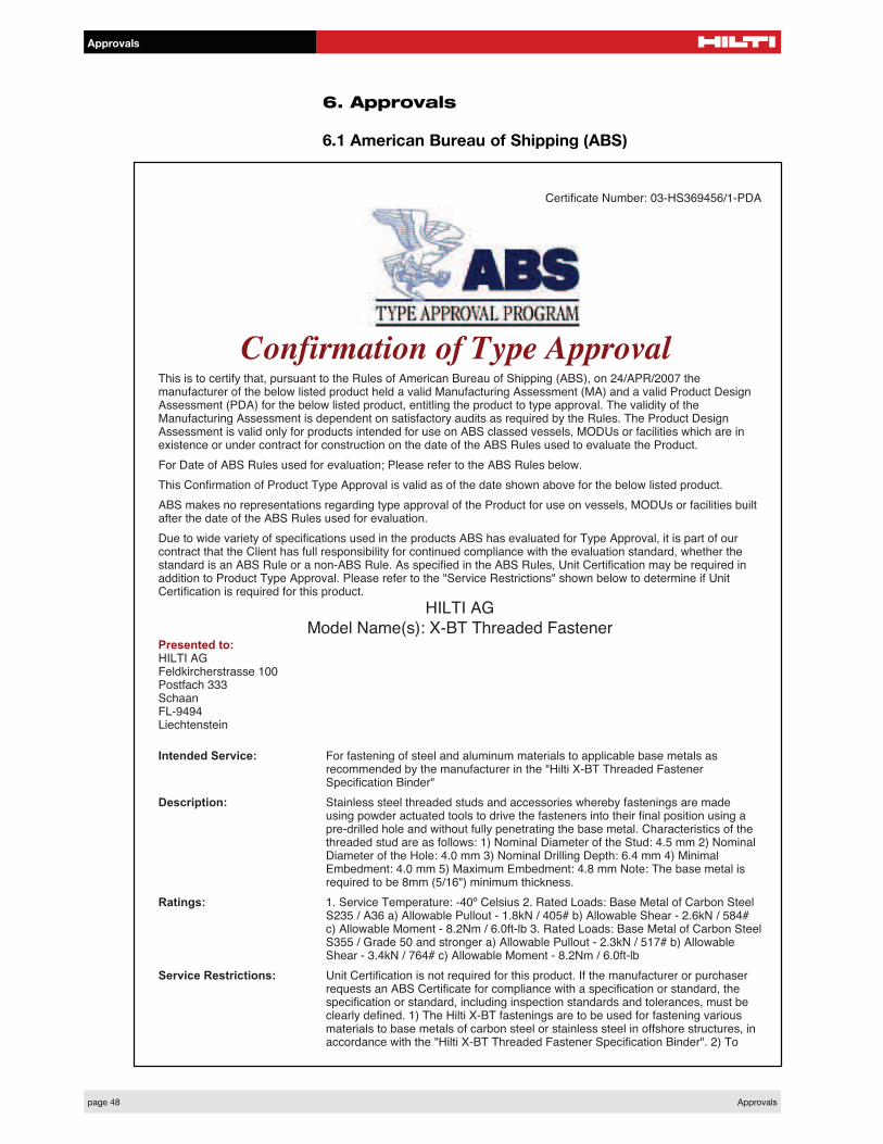
Certificate Number: 03-HS369456/1-PDA
Confirmation of Type ApprovalThis is to certify that, pursuant to the Rules of American Bureau of Shipping (ABS), on 24/APR/2007 themanufacturer of the below listed product held a valid Manufacturing Assessment (MA) and a valid Product DesignAssessment (PDA) for the below listed product, entitling the product to type approval. The validity of theManufacturing Assessment is dependent on satisfactory audits as required by the Rules. The Product DesignAssessment is valid only for products intended for use on ABS classed vessels, MODUs or facilities which are inexistence or under contract for construction on the date of the ABS Rules used to evaluate the Product.
For Date of ABS Rules used for evaluation; Please refer to the ABS Rules below.
This Confirmation of Product Type Approval is valid as of the date shown above for the below listed product.
ABS makes no representations regarding type approval of the Product for use on vessels, MODUs or facilities builtafter the date of the ABS Rules used for evaluation.
Due to wide variety of specifications used in the products ABS has evaluated for Type Approval, it is part of ourcontract that the Client has full responsibility for continued compliance with the evaluation standard, whether thestandard is an ABS Rule or a non-ABS Rule. As specified in the ABS Rules, Unit Certification may be required inaddition to Product Type Approval. Please refer to the "Service Restrictions" shown below to determine if UnitCertification is required for this product.
HILTI AG
Model Name(s): X-BT Threaded FastenerPresented to:HILTI AGFeldkircherstrasse 100Postfach 333SchaanFL-9494Liechtenstein
Intended Service: For fastening of steel and aluminum materials to applicable base metals asrecommended by the manufacturer in the "Hilti X-BT Threaded FastenerSpecification Binder"
Description: Stainless steel threaded studs and accessories whereby fastenings are madeusing powder actuated tools to drive the fasteners into their final position using apre-drilled hole and without fully penetrating the base metal. Characteristics of thethreaded stud are as follows: 1) Nominal Diameter of the Stud: 4.5 mm 2) NominalDiameter of the Hole: 4.0 mm 3) Nominal Drilling Depth: 6.4 mm 4) MinimalEmbedment: 4.0 mm 5) Maximum Embedment: 4.8 mm Note: The base metal isrequired to be 8mm (5/16") minimum thickness.
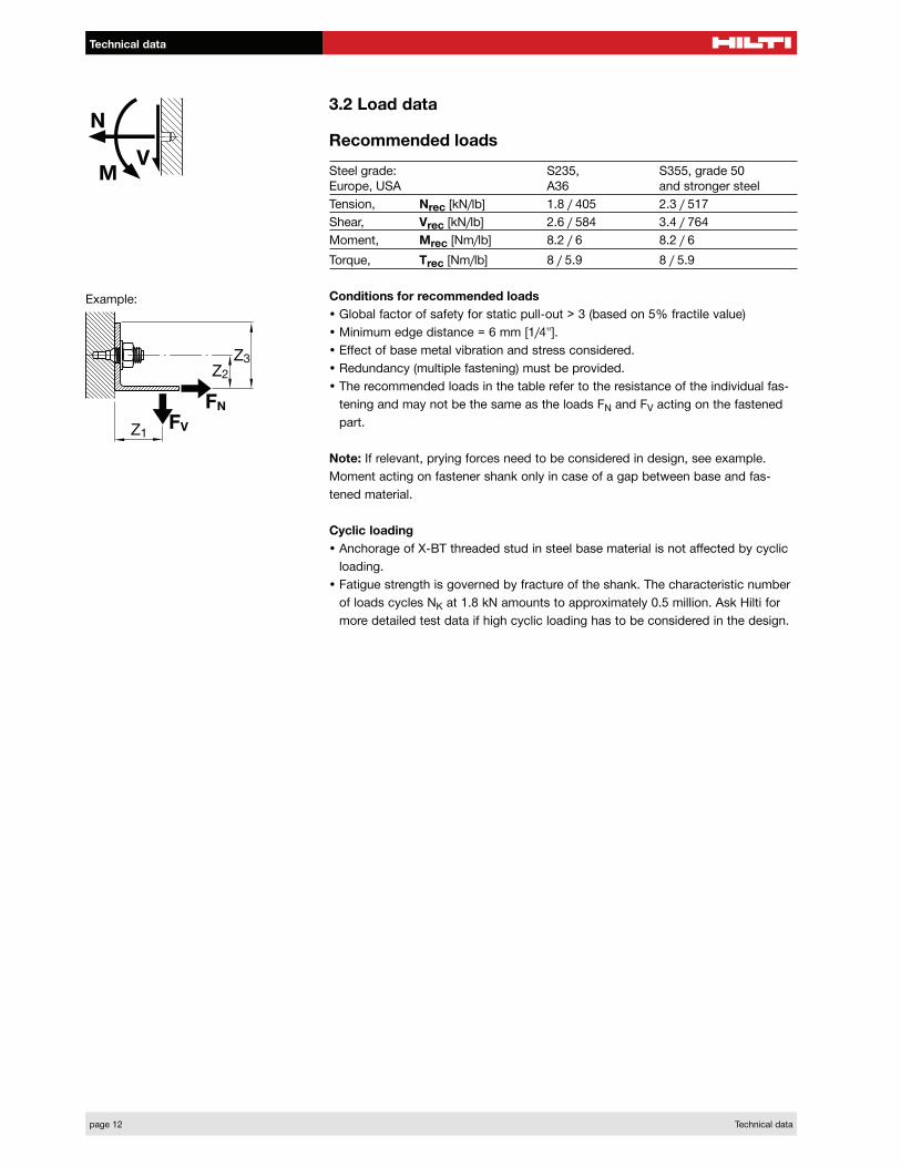
Ratings: 1. Service Temperature: -40º Celsius 2. Rated Loads: Base Metal of Carbon SteelS235 / A36 a) Allowable Pullout - 1.8kN / 405# b) Allowable Shear - 2.6kN / 584#c) Allowable Moment - 8.2Nm / 6.0ft-lb 3. Rated Loads: Base Metal of Carbon SteelS355 / Grade 50 and stronger a) Allowable Pullout - 2.3kN / 517# b) AllowableShear - 3.4kN / 764# c) Allowable Moment - 8.2Nm / 6.0ft-lb
Service Restrictions: Unit Certification is not required for this product. If the manufacturer or purchaserrequests an ABS Certificate for compliance with a specification or standard, thespecification or standard, including inspection standards and tolerances, must beclearly defined. 1) The Hilti X-BT fastenings are to be used for fastening variousmaterials to base metals of carbon steel or stainless steel in offshore structures, inaccordance with the "Hilti X-BT Threaded Fastener Specification Binder". 2) To
ensure that proper anchoring/fastening mechanisms take place, i.e. pressing andfusing, the following fastening tools as recommended by the manufacturer shall beused: a) Drill bit - TX-BT 4/7. b) Tool DX 351-BT(G). c) Power Load 6.8/11M Brown3) Minimum base metal strengths are to be as follows: a) Carbon Steel : UltimateTensile Strength (fu) = 360 N/mm2 (53.53 ksi ) b) Stainless Steel : Ultimate TensileStrength (fu) = 360 N/mm2 (53.53 ksi ) 4) The fasteners are to be installed usinginstallation procedures as recommended by the manufacturer. 5) In general, typeapproved X-BT fasteners are not to be used for the following locations: a) OnStructural members that are sensitive to stress patterns or variations b) In Areaswhere notch toughness is of paramount importance c) For attachment of structuralfire protection insulation. d) On bulkheads/decks with a thickness less than 8 mme) Watertight boundaries 6) Type approved X-BT fasteners, if installed in fire rateddivisions, shall be installed without the washer. 7) In general, the Hilti X-BTfasteners may be used to fasten materials in areas where welding or drilling forbolting is permissible. It is recommended that the fasteners be installed no closerthan 6 mm from the edge of a flange or cutout and no closer than 15 mm betweenfasteners. The following additional guidance is provided for applications onoffshore structures: a) Acceptable applications: i) The securing of grating panels ii)The securing of checker plate iii) The securing of electrical cable trays iv) Thesecuring of electrical cable clips v) The securing of joiner bulkhead tracks to platingin deck modules vi) The securing of light duty fixtures and light hangers b)Acceptable locations: i) On Topside Deck members and plating ii) On DeckModules iii) On members and plating in non-tight bulkheads and flats of hulls iv) Onmembers in longitudinal and transverse frames of hulls c) Applications or locationswhere special care is recommended (see d below): i) In members with significantthermal stresses ii) In highly stressed portions of members iii) In members subjectto high, cyclic loads iv) Hangers for pipe systems with high thermal stresses v)Hangers for sprinkler systems d) The Hilti X-BT fasteners may be used for theapplications where special care is recommended by following the manufacturer'srecommendations and guidance and obtaining approval from the Ow
Comments: ABS approvals are generally based on the product test reports furnished byrecognized institutions and laboratories, which may reflect specific local conditions.If any application is in a jurisdiction where the fasteners are subject to an approvalprocess or where specific guidelines are to be followed, the approved technicaldata or the specific design guidelines shall be followed.
Notes / Documentation: This Product Design Assessment (PDA) is valid only for products intended for useon ABS classed vessels, MODUs or facilities which are in existence or undercontract for construction on the date of the ABS Rules used to evaluate theProduct.
Term of Validity: This Design Assessment Certificate number 03-HS369456/1-PDA, dated23/Apr/2007 will expire on 22/Apr/2012 or at an earlier date should there bealterations to the product's design or changes to the referenced ABS Rules andother specifications, which affect the product. Product use on or after 1 January2008, will be subject to compliance with the ABS Rules or specifications in effectwhen the vessel, MODU or facility is contracted. The product's acceptability onboard ABS-classed vessels or facilities is defined in the service restrictions of thiscertificate.
ABS Rules: 2007 Steel Vessel Rules 1-1-4/7.7,2006 MODU Rules 3-2-2/11; 4-3-3/5.9
National Standards:International Standards:Government Authority:EUMED:Others: None
Manager, ABS ProgramsABS has used due diligence in the preparation of this certificate and it represents the information on the product in the ABS Records as of thedate and time the certificate was printed. Type Approval requires Drawing Assessment, Prototype Testing and assessment of themanufacturer's quality assurance and quality control arrangements. Limited circumstances may allow only Prototype Testing to satisfy Type
Approval. The approvals of Drawings and Products remain valid as long as the ABS Rule, to which they were assessed, remains valid. ABScautions manufacturers to review and maintain compliance with all other specifications to which the product may have been assessed. Further,unless it is specifically indicated in the description of the product; Type Approval does not necessarily waive witnessed inspection or surveyprocedures (where otherwise required) for products to be used in a vessel, MODU or facility intended to be ABS classed or that is presently inclass with ABS. Questions regarding the validity of ABS Rules or the need for supplemental testing or inspection of such products should, in allcases, be addressed to ABS.

Certificate Number: 03-HS369884/1-PDA
Confirmation of Type ApprovalThis is to certify that, pursuant to the Rules of American Bureau of Shipping (ABS), on 29/MAY/2008 themanufacturer of the below listed product held a valid Manufacturing Assessment (MA) and a valid Product DesignAssessment (PDA) for the below listed product, entitling the product to type approval. The validity of theManufacturing Assessment is dependent on satisfactory audits as required by the Rules. The Product DesignAssessment is valid only for products intended for use on ABS classed vessels, MODUs or facilities which are inexistence or under contract for construction on the date of the ABS Rules used to evaluate the Product.
For Date of ABS Rules used for evaluation; Please refer to the ABS Rules below.
This Confirmation of Product Type Approval is valid as of the date shown above for the below listed product.
ABS makes no representations regarding type approval of the Product for use on vessels, MODUs or facilities builtafter the date of the ABS Rules used for evaluation.
Due to wide variety of specifications used in the products ABS has evaluated for Type Approval, it is part of ourcontract that the Client has full responsibility for continued compliance with the evaluation standard, whether thestandard is an ABS Rule or a non-ABS Rule. As specified in the ABS Rules, Unit Certification may be required inaddition to Product Type Approval. Please refer to the "Service Restrictions" shown below to determine if UnitCertification is required for this product.
HILTI AG
Model Name(s): Fasteners: X-BT M8-15-6-R, X-BT M10-24-6-R, X-BT
W10-24-6-R, X-BT M8-15-6-SN12-R, X-BT M10-24-6 SN12-R, X-BT W10-24-6
SN12-R, Drilling Tool: XBT 4000-A & TX-BT 4/7 drills, Fastening Tool: DX 351-BT
& DX 351-BTGPresented to:HILTI AGFeldkircherstrasse 100Postfach 333SchaanFL-9494Liechtenstein
Intended Service: For fastening of fastened materials to base materials of carbon steel or stainlesssteel in the ship and shipbuilding environment.
Description: Corrosion resistant steel threaded studs and accessories whereby fastening aremade by using power actuated tools to drive the fasteners into their final positionsthrough a pre-drilled hole and without having to penetrate the base materails, in aprocess of pressing and fusing.
Ratings: Refer to "Hilti X-BT Threaded Fastener Specification Binder" for the recommendedmaximum loading in tension, shear, moment and torque, in association with the'Conditions for recommended loads' specified therein.
Service Restrictions: Unit certification is not required for this product. 1) The Hilti X-BT fastenings are tobe used for fastening various materials to base metals of carbon/ stainless steel inship structures, i.a.w. the "Hilti X-BT Threaded Fastener Specification Binder". 2)To ensure that proper anchoring/fastening mechanisms take place, i.e. pressingand fusing, the following fastening tools as recommended by the manufacturershall be used: Drill bit: TX-BT 4/7, Fastening Tool: DX 351-BT & DX 351-BTG,Power Load 6.8/11M Brown. 3) Minimum base metal strengths are to be as follows:a) Carbon Steel: Ult.Tensile Strength (fu) = 360 N/mm2 (53.53 ksi) b) Stainless

Steel: Ult. Tensile Strength (fu) = 360 N/mm2 (53.53 ksi) 4) The fasteners are to beinstalled using installation procedures recommended by the manufacturer. 5) Ingeneral, type approved X-BT fasteners are not to be used for the followinglocations: a) On structural members that are sensitive to stress patterns orvariations b) In areas where notch toughness is of paramount importance c) Forattachment of structural fire protection insulation. d) On bulkheads/decks with athickness less than 8 mm e) Watertight boundaries 6) Type approved X-BTfasteners, if installed in fire rated divisions, shall be installed without the washer. 7)In general, the Hilti X-BT fasteners may be used to fasten materials in areas wherewelding or drilling for bolting is permissible. It is recommended that fasteners beinstalled no closer than 6 mm from the edge of a flange or cutout and no closerthan 15 mm between fasteners. The following additional guidance is provided forapplications on ship structures: a) Acceptable applications: i) The securing ofgrating panels ii) The securing of checker plate iii) The securing of electrical cabletrays iv) The securing of electrical cable clips v) The securing of joiner bulkheadtracks to plating in deck modules vi) The securing of light duty fixtures and lighthangers b) Acceptable locations: i) On platform decks ii) On non-tight bulkheads.iii) On lower decks iv) On transverse side frames v) In superstructures anddeckhouse bulkheads vi) Securing of items 7a (i-vi)) above and similar items inA-class boundaries. c) Applications or locations where special care isrecommended (see d below): i) In members with significant thermal stresses ii) Inhighly stressed portions of members iii) In members subject to high, cyclic loads iv)Hangers for pipe systems with high thermal stresses v) Hangers for sprinklersystems d) The Hilti X-BT fasteners may be used for the applications where specialcare is recommended by following the manufacturer's recommendations andguidance and obtaining approval from the Owner and the attending Surveyor. 8)Hilti X-BT fasteners may also be used for applications other than those listedabove, subject to specific engineering approval for the application prior toinstallation. See also the Guidance Notes for DX-fasteners(ship application)
Comments: ABS approvals are general based on the product test reports furnished byrecognized institutions and laboratories which may reflect specific local conditions.If any application is in a jurisdiction where the fasteners are subject to the approvalprocess or specific guidelines are to be followed, the approved technical data ordesign guidelines take precedence over technical data presented herein.
Notes / Documentation: This Product Design Assessment (PDA) is valid only for products intended for useon ABS classed vessels, MODUs or facilities which are in existence or undercontract for construction on the date of the ABS Rules used to evaluate theProduct.
Term of Validity: This Design Assessment Certificate number 03-HS369884/1-PDA, dated13/May/2008 will expire on 12/May/2013 or at an earlier date should there bealterations to the product's design or changes to the referenced ABS Rules andother specifications, which affect the product. Product use on or after 1 January2009, will be subject to compliance with the ABS Rules or specifications in effectwhen the vessel, MODU or facility is contracted. The product's acceptability onboard ABS-classed vessels or facilities is defined in the service restrictions of thiscertificate.
ABS Rules: 2008 Steel Vessels Rule1-1-4/7.7, 4-8-4/21.9
National Standards:International Standards:Government Authority:EUMED:Others: Manufacturer's standards
Manager, ABS ProgramsABS has used due diligence in the preparation of this certificate and it represents the information on the product in the ABS Records as of thedate and time the certificate was printed. Type Approval requires Drawing Assessment, Prototype Testing and assessment of themanufacturer's quality assurance and quality control arrangements. Limited circumstances may allow only Prototype Testing to satisfy TypeApproval. The approvals of Drawings and Products remain valid as long as the ABS Rule, to which they were assessed, remains valid. ABS
cautions manufacturers to review and maintain compliance with all other specifications to which the product may have been assessed. Further,unless it is specifically indicated in the description of the product; Type Approval does not necessarily waive witnessed inspection or surveyprocedures (where otherwise required) for products to be used in a vessel, MODU or facility intended to be ABS classed or that is presently inclass with ABS. Questions regarding the validity of ABS Rules or the need for supplemental testing or inspection of such products should, in allcases, be addressed to ABS.


ICC-ES Evaluation Reports are not to be construed as representing aesthetics or any other attributes not specifically addressed, nor are they to be construed as an endorsement of the subject of the report or a recommendation for its use. There is no warranty by ICC Evaluation Service, Inc., express or implied, as to any finding or other matter in this report, or as to any product covered by the report.
Copyright © 2009 Page 1 of 5
ICC-ES Evaluation Report ESR-2347Reissued December 1, 2009
This report is subject to re-examination in two years.
www.icc-es.org | (800) 423-6587 | (562) 699-0543 A Subsidiary of the International Code Council®
DIVISION: 05—METALS Section: 05090—Metal Fastenings
REPORT HOLDER:
HILTI, INC. 5400 SOUTH 122
ND EAST AVENUE
TULSA, OKLAHOMA 74146 (800) 879-8000 [email protected]
EVALUATION SUBJECT:
HILTI LOW-VELOCITY POWDER-ACTUATED DRIVEN THREADED STUDS FOR ATTACHMENT TO STEEL
1.0 EVALUATION SCOPE
Compliance with the following codes:
2009 International Building Code® (2009 IBC)
2009 International Residential Code® (2009 IRC)
2006 International Building Code® (2006 IBC)*
2006 International Residential Code® (2006 IRC)*
2003 International Building Code® (2003 IBC)*
2003 International Residential Code® (2003 IRC)*
2000 International Building Code® (2000 IBC)*
2000 International Residential Code® (2000 IRC)*
1997 Uniform Building Code™ (UBC)*
*Codes indicated with an asterisk are addresses in Section 8.0
Property evaluated:
Structural
2.0 USES
The Hilti Powder-Actuated Driven Threaded Studs are used as alternatives to the bolts used to attach materials to structural steel, which are described in IBC Section 2204.2. The fasteners may be used for structures regulated under the IRC, when an engineered design is submitted in accordance with IRC Section R301.1.3.
3.0 DESCRIPTION
3.1 General:
Hilti low-velocity powder-actuated threaded studs are fasteners with male threads for attachment on one end and a pointed- or blunt-tip shank on the other end for
embedment into the supporting steel. Both types may be supplied with a plastic washer for the carbon steel fasteners or a stainless steel washer for the stainless steel fasteners. The threaded studs with pointed-tip shanks are driven directly into the steel. The threaded studs with blunt-tip shanks (X-BT type) are driven into a predrilled pilot hole. The threaded studs are available with the thread designations and lengths and in the materials shown in Table 1. See Figures 1 and 2 for illustrations of pointed- and blunt-tip shank threaded studs.
3.2 Materials:
Carbon steel threaded studs are manufactured from hardened steel and are zinc-plated in accordance with ASTM B 633 SC 1, Type III. Stainless steel threaded studs are composed of two main parts, the threaded sleeve and the drive pin. The threaded sleeve and washer are manufactured from SAE 316 stainless steel. The drive pin is manufactured from a proprietary CrNiMo alloy complying with the requirements of SAE 316.
3.3 Steel Substrates:
Structural steel must comply with ASTM A 36 and have minimum thicknesses as shown in Tables 2 and 3.
4.0 DESIGN AND INSTALLATION
4.1 Design:
4.1.1 General: The allowable shear and tension service loads for the threaded studs installed in steel are found in Tables 2 and 3. The allowable loads or load combinations for the fasteners are not allowed to be adjusted for fasteners subjected to wind loads. Except for fasteners used with architectural, electrical and mechanical components as described in Section 13.1.4 of ASCE/SEI 7, use of fasteners to resist earthquake loads is outside the scope of this report.
Allowable loads for fasteners subjected to combined shear and tension forces are determined by the following formula:
(Ps/Pt) + (Vs/Vt) 1
where:
Ps = Applied service tension load, pounds (N).
Pt = Allowable service tension load, pounds (N).
Vs = Applied service shear load, pounds (N).
Vt = Allowable service shear load, pounds (N).
4.1.2 Wood to Steel Connections: Reference lateral design loads for fasteners determined in accordance with Part 11 of ANSI/AF&PA NDS-2005 are applicable to Hilti

ESR-2347 | Most Widely Accepted and Trusted Page 2 of 5
fasteners of equal or greater diameters. The wood element must be considered to be the side member. The fastener bending yield strength is allowed to be taken as the value noted in the NDS, based on the fastener diameter.
4.2 Installation:
4.2.1 General: The powder-actuated threaded studs must be installed in accordance with this report and the manufacturer’s published installation instructions. A copy of these instructions must be available on the jobsite at all times during installation. Installation is limited to dry, interior locations, except for stainless steel fasteners, which may be installed in exterior or damp environments.
Fastener placement requires the use of a Hilti low-velocity powder-actuated tool in accordance with Hilti recommendations. Threaded studs must be installed with stud stand-off, hNVS, dimensions as defined in Figure 3 and Table 1. Minimum spacing between fasteners must be 1 inch (25.4 mm) and minimum edge distance must be
1/2
inch (12.7 mm). Installers must be certified by Hilti and have a current, Hilti-issued, operator’s license.
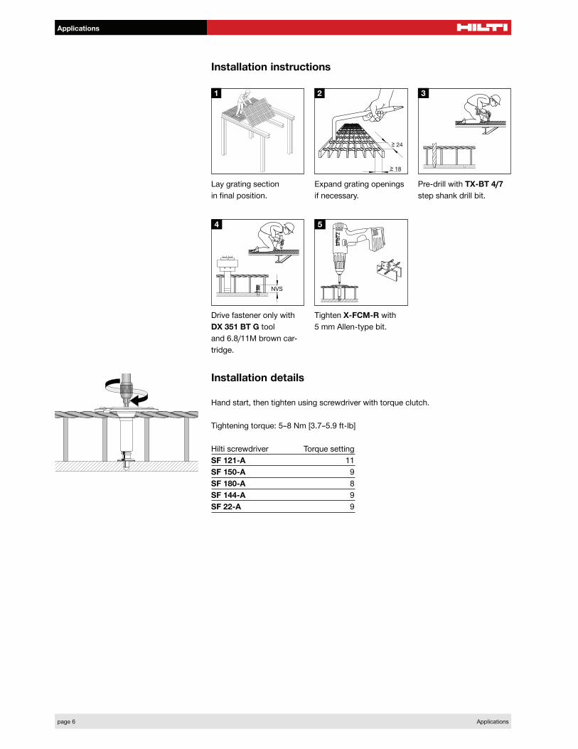
4.2.2 X-BT Blunt-tip Threaded Studs: The X-BT blunt-tip threaded studs require a pilot hole predrilled to the required depth with a Hilti TX-BT 4/7 step shank drill bit, in accordance with the manufacturer’s published installation instructions. Installation instructions for the X-BT threaded studs are illustrated in Figure 5.
5.0 CONDITIONS OF USE
The Hilti Low-Velocity Powder-Actuated Driven Threaded Studs described in this report comply with, or are suitable alternatives to what is specified in, those codes listed in Section 1.0 of this report, subject to the following conditions:
5.1 The fasteners are manufactured and identified in accordance with this report.
5.2 Fastener installation complies with this report and the Hilti, Inc., published instructions. In the event of conflict between this report and the Hilti, Inc., published instructions, this report governs.
5.3 Allowable tension and shear values are as noted in this report. The stress increases and load reductions described in IBC Section 1605.3.2 are not allowed for wind loads acting alone or when combined with gravity loads. No increase is allowed for vertical loads acting alone.
5.4 Calculations demonstrating that the applied loads are less than the allowable loads described in this report must be submitted to the code official for approval. The calculations are to be prepared by a registered design professional where required by the statutes of the jurisdiction in which the project is constructed.
5.5 Except for fasteners used with architectural, electrical and mechanical components as described in Section 13.1.4 of ASCE/SEI 7, use of fasteners to resist earthquake loads is outside the scope of this report.
5.6 Stainless steel threaded studs may be installed in exterior, damp environments. Use of carbon steel threaded studs is limited to dry, interior locations.
5.7 Hilti stainless steel threaded studs may be installed in contact with preservative-treated wood, as set forth in the applicable code. Use of carbon steel threaded studs in contact with preservative-treated or fire-retardant-treated wood is beyond the scope of this report.
6.0 EVIDENCE SUBMITTED
Data in accordance with the ICC-ES Acceptance Criteria for Fasteners Power-driven into Concrete, Steel and Masonry Elements (AC70), dated October 2006.
7.0 IDENTIFICATION
Each package of fasteners is labeled with the product designation, the manufacturer’s name (Hilti), and the evaluation report number (ESR-2347). An “H”, for Hilti, is imprinted on the head of each carbon steel threaded stud. An “HI” is imprinted on the head of each stainless steel threaded stud. These imprints are shown in Figure 4
8.0 OTHER CODES
8.1 Evaluation Scope:
In addition to the codes referenced in Section 1.0, the products in this report were evaluated for compliance with the requirements of the following codes:
2006 International Building Code® (2006 IBC)
2006 International Residential Code® (2006 IRC)
2003 International Building Code® (2003 IBC)
2003 International Residential Code® (2003 IRC)
2000 International Building Code® (2000 IBC)
2000 International Residential Code® (2000 IRC)
1997 Uniform Building Code™ (UBC)
8.2 Uses:
The Hilti Powder-Actuated Driven Threaded Studs are used as alternatives to the bolts used to attach materials to structural steel, as described in 2006 and 2003 IBC Section 2204.2, 2000 IBC Section 2209, and UBC Section 2205.11. The fasteners may be used for structures regulated under the IRC, when an engineered design is submitted in accordance with 2006 and 2003 IRC Section R301.1.3 or 2000 IRC Section R301.1.2, as applicable.
8.3 Description:
See Section 3.0
8.4 Design and Installation:
8.4.1 Design: See Section 4.1.1, with the following modifications:
! The stress increases and load reductions described in Section 1605.3 of the 2006, 2003 and 2000 IBC, and the stress increases described in Section 1612.3.2 of the UBC, are not allowed for wind loads acting alone or when combined with gravity loads. No increase is allowed for vertical loads acting alone.
! Except for fasteners used with architectural, electrical and mechanical components as described in Section Section 13.1.4 of ASCE/SEI 7-05 (2006 IBC and IRC), Section 9.6.1 of ASCE/SEI 7-02 (2003 IBC and 2003 IRC) or Section 9.6.1 of ASCE/SEI 7-98 (2000 IBC and 2000 IRC), use of fasteners to resist earthquake loads is outside the scope of this report.
See Section 4.1.2, with the following modification:
! Reference lateral design loads for fasteners determined in accordance with Part 11 of ANSI/AF&PA NDS-2005 (2006 IBC and 2006 IRC), Part 11 of ANSI/AF&PA NDS-2001 (2003 IBC and 2003 IRC), Part 12 of ANSI/AF&PA NDS-1997 (2000 IBC and 2000 IRC), or Part XII of ANSI/NFoPA NDS-1991 (UBC), as applicable, are applicable to Hilti fasteners of equal or greater diameters.

ESR-2347 | Most Widely Accepted and Trusted Page 3 of 5 8.4.2 Installation: See Section 4.2. 8.5 Conditions of Use:See Section 5.0, and the following: 8.5.1 Allowable tension and shear loads are as noted in Section 4.1.1. The stress increases and load reductions described in Section 1605.3 of the 2006, 2003 and 2000 IBC, and the stress increases described in Section 1612.3.2 of the UBC, are not allowed for wind loads acting alone or when combined with gravity loads. No increase is allowed for vertical loads acting alone. 8.5.2 Except for fasteners used with architectural, electrical and mechanical components as described in
Section 13.1.4 of ASCE/SEI 7-05 (2006 IBC and IRC), Section 9.6.1 of ASCE/SEI 7-02 (2003 IBC and IRC) or Section 9.6.1 of ASCE/SEI 7-98 (2000 IBC and IRC), use of fasteners to resist earthquake loads is outside the scope of this report. 8.6 Evidence Submitted:See Section 6.0. 8.7 Identification:See Section 7.0.
TABLE 1ó THREADED STUD DESCRIPTIONS
DESIGNATION THREAD DESIGNATION
SHANK DIAMETER
in. (mm)
NOMINAL THREAD LENGTH in. (mm)
NOMINAL SHANK
LENGTH in. (mm)
MATERIAL2 THREADED STUD STAND-OFF, hNVS1
in. (mm) Pointed-Tip
X-EW6H-11-9 UNC 1/4-inch 0.145 (3.7) 7/16 (11) 3/8 (9) CS 3/8 ñ 1/2 ( 9.5 - 12.5) X-EW6H-20-9 UNC 1/4-inch 0.145 (3.7) 3/4 (20) 3/8 (9) CS 23/32 ñ 27/32 ( 18.5 - 21.5) X-EW6H-28-9 UNC 1/4-inch 0.145 (3.7) 11/8 (28) 3/8 (9) CS 11/16 ñ 15/32 (26.5 - 29.5) X-EW6H-38-9 UNC 1/4-inch 0.145 (3.7) 11/2 (38) 3/8 (9) CS 17/16 ñ 19/16 (36.5 - 39.5) X-EM8H-11-12 Metric 8 mm 0.177 (4.5) 7/16 (11) 1/2 (12) CS 7/16 ñ 5/8 (11.5 - 15.5) X-EM8H-15-12 Metric 8 mm 0.177 (4.5) 5/8 (15) 1/2 (12) CS 5/8 ñ 3/4 (15.5 - 19.5) X-EM8H-25-12 Metric 8 mm 0.177 (4.5) 1 (25) 1/2 (12) CS 1 ñ 15/32 (25.5 - 29.5) X-EM8H-35-12 Metric 8 mm 0.177 (4.5) 13/8 (35) 1/2 (12) CS 13/8 ñ 19/16 (35.5 - 39.5)
X-EW10H-30-14 UNC 3/8-inch 0.205 (5.2) 13/16 (30) 9/16 (14) CS 13/32 ñ 17/32 (28.0 - 31.0) X-CRM8-9-12 Metric 8 mm 0.158 (4.0) 3/8 (9) 1/2 (12) SS 7/16 - 19/32 (11.0 ñ 15.0)
X-CRM8-15-12 Metric 8 mm 0.158 (4.0) 5/8 (15) 1/2 (12) SS 5/8 - 25/32 (16.0 ñ 20.0) Blunt-Tip
X-BT M8-15-6 Metric 8 mm 0.177 (4.5) 5/8 (15) 1/4 (6) SS 5/8 ñ 11/16 (15.7 - 16.8) X-BT M8-15-6 SN12-R Metric 8 mm 0.177 (4.5) 5/8 (15) 1/4 (6) SS 5/8 ñ 11/16 (15.7 - 16.8)
X-BT W10-24-6 UNC 3/8-inch 0.177 (4.5) 15/16 (24) 1/4 (6) SS 1 - 11/16 (25.7 ñ 26.8) X-BT W10-24-6 SN12-R UNC 3/8-inch 0.177 (4.5) 15/16 (24) 1/4 (6) SS 1 - 11/16 (25.7 ñ 26.8)
X-BT M10-24-6 Metric 10 mm 0.177 (4.5) 15/16 (24) 1/4 (6) SS 1 - 11/16 (25.7 ñ 26.8) X-BT M10-24-6 SN12-R Metric 10 mm 0.177 (4.5) 15/16 (24) 1/4 (6) SS 1 - 11/16 (25.7 ñ 26.8)
1See Figure 3 for depiction of hNVS.2CS = Carbon steel, SS = Stainless steel.
TABLE 2ó ALLOWABLE LOADS FOR POINTED-TIP THREADED STUDS DRIVEN INTO STEEL 1, 2, 3 (lbf)
Fastener Shank Dia. (in.)
Steel Thickness (in.) 3/16 1/4 3/8 1/2
3/4Tension Shear Tension Shear Tension Shear Tension Shear Tension Shear
X-EW6H 0.145 360 500 500 600 500 600 500 600 - - X-EM8H 0.177 - - 700 700 700 700 700 700 - -
X-EW10H 0.205 - - 970 1000 1100 1100 1100 1100 800 800 X-CRM8 0.158 - - 405 405 405 405 405 405 - -
For SI: 1 inch = 25.4 mm, 1 lbf = 4.4 N, 1 psi = 6895 Pa. Notes:1The tabulated allowable load values are for the threaded studs only. Wood or steel members connected to the substrate must be investigated in accordance with accepted design criteria. 2Tabulated allowable load values based upon embedment in steel such that threaded stud stand-off, hNVS, complies with Table 1. 3All allowable load capacities above are based on base steel complying with ASTM A 36, with minimum yield strength (Fy) of 36 ksi and minimum tensile strength of 58 ksi.
ESR-2347 | Most Widely Accepted and Trusted Page 4 of 5
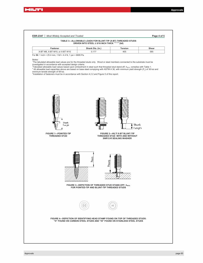
TABLE 3—ALLOWABLE LOADS FOR BLUNT-TIP (X-BT) THREADED STUDS DRIVEN INTO STEEL 5/16 INCH THICK
1, 2, 3, 4 (lbf)
Fastener Shank Dia. (in.) Tension Shear
X-BT M8, X-BT M10, or X-BT W10 0.177 405 585
For SI: 1 inch = 25.4 mm, 1 lbf = 4.4 N, 1 psi = 6895 Pa.
Notes:1The tabulated allowable load values are for the threaded studs only. Wood or steel members connected to the substrate must be
investigated in accordance with accepted design criteria. 2Tabulated allowable load values based upon embedment in steel such that threaded stud stand-off, hNVS, complies with Table 1.
3 All allowable load capacities above are based on base steel complying with ASTM A 36, with minimum yield strength (Fy) of 36 ksi and
minimum tensile strength of 58 ksi. 4Installation of fasteners must be in accordance with Section 4.2.2 and Figure 5 of this report.
FIGURE 1—POINTED-TIP FIGURE 2—HILTI X-BT BLUNT-TIP THREADED STUD THREADED STUD WITH AND WITHOUT SNR12-R SEALING WASHER
FIGURE 3—DEPICTION OF THREADED STUD STAND-OFF, hNVS,FOR POINTED-TIP AND BLUNT-TIP THREADED STUDS
FIGURE 4—DEPICTION OF IDENTIFYING HEAD STAMP FOUND ON TOP OF THREADED STUDS: “H” FOUND ON CARBON STEEL STUDS AND “HI” FOUND ON STAINLESS STEEL STUDS

ESR-2347 | Most Widely Accepted and Trusted Page 5 of 5
FIGURE 5—INSTALLATION INSTRUCTIONS FOR HILTI X-BT THREADED STUDS
