x-fem crack modeling - cea - hpc · x-fem crack modeling nicolas moËs ecole centrale de nantes...
TRANSCRIPT

X-FEM crack modeling
Nicolas MOËSEcole Centrale de Nantes
Institut GeM - CNRS

Modelling the tip
(Belytschko and Black 99)
(Moës, Dolbow, Belytschko 99)

Propagation of two cracks emanating from holes
Belytschko et al. 2000

SIF ComputationInclined elliptical crack
Tension loading
Exact (continuous line) and estimated SIFs

X-FEM
Crack represented by level-sets− Local coodinates at the crack tip
lsn
lst

Level Set Description of the Crack
φ x,t ,ψ x,t 0
φ x,t ,ψ x,t =0
ψ x,t 0
Defines the crack location
Gives the crack front
does not intersect the crack
The level set function are assumed to be orthogonal
∇φ⋅∇ψ=0 ∀ t
Stolarska et al. 2001, Belytschko et al. 2001, Moës et al. 2002

Crack growth : penny-shaped crack
The color indicates the trace of the front level set on the crackGravouil et al. 2002

Crack growth : Lens-shaped crack
Notice the change in topology of the crack front 1 front, then 4 frontsGravouil et al. 2002

Crack growth :Cracked beam in bending
The crack front is rotating as it moves downward to reach mode IGravouil et al. 2002

Model problem for convergence analysis
• Semi infinite plane crack in an infinite domain. Exact solution for mixed opening mode is known
• Computation domain is a square
• Traction computed from the exact solution are imposed on the boundaries of the computation domain.

Convergence

Choice of α
The field α describes the geometry of the integration domain S.
Two choices of integration domain with regard to h:– Topological
– Geometrical

Episode 1 :Topological / Geometrical enrichment

(Laborde, Pommier et al. 05), (Béchet, Minnebo et al. 05)

Episode 2 : Conditioning issues.

One way to cure : Pre-preconditionner
•Efficient pre-preconditoner based on the orthogonalization of
the shape functions on each support. This is performed on the
matrix thus only algebraic operations.
(Béchet, Minnebo et al. 05). It somehow generalizes the shifted basis.

Another way to cure : Reduce the number of freedom while maintaining the convergence.
•Idea 1 : Tie all degrees of freedom together on the enrichment support giving only 4 global enrichment functions. Unfortunately loss of convergence rate.
•Idea 2 : Disconnected the enrichment zone from the rest
and reconnects. Optimal rate recovered but rather complex
•Idea 3 : Use of a very smooth cut-off function multiplying
the enrichment. Optimal rate. (but the error is larger than
when all nodes enriched).
(Laborde, Pommier et al. 05) (Chahine, Laborde et al. 08)

(Chahine, Laborde et al. 08)
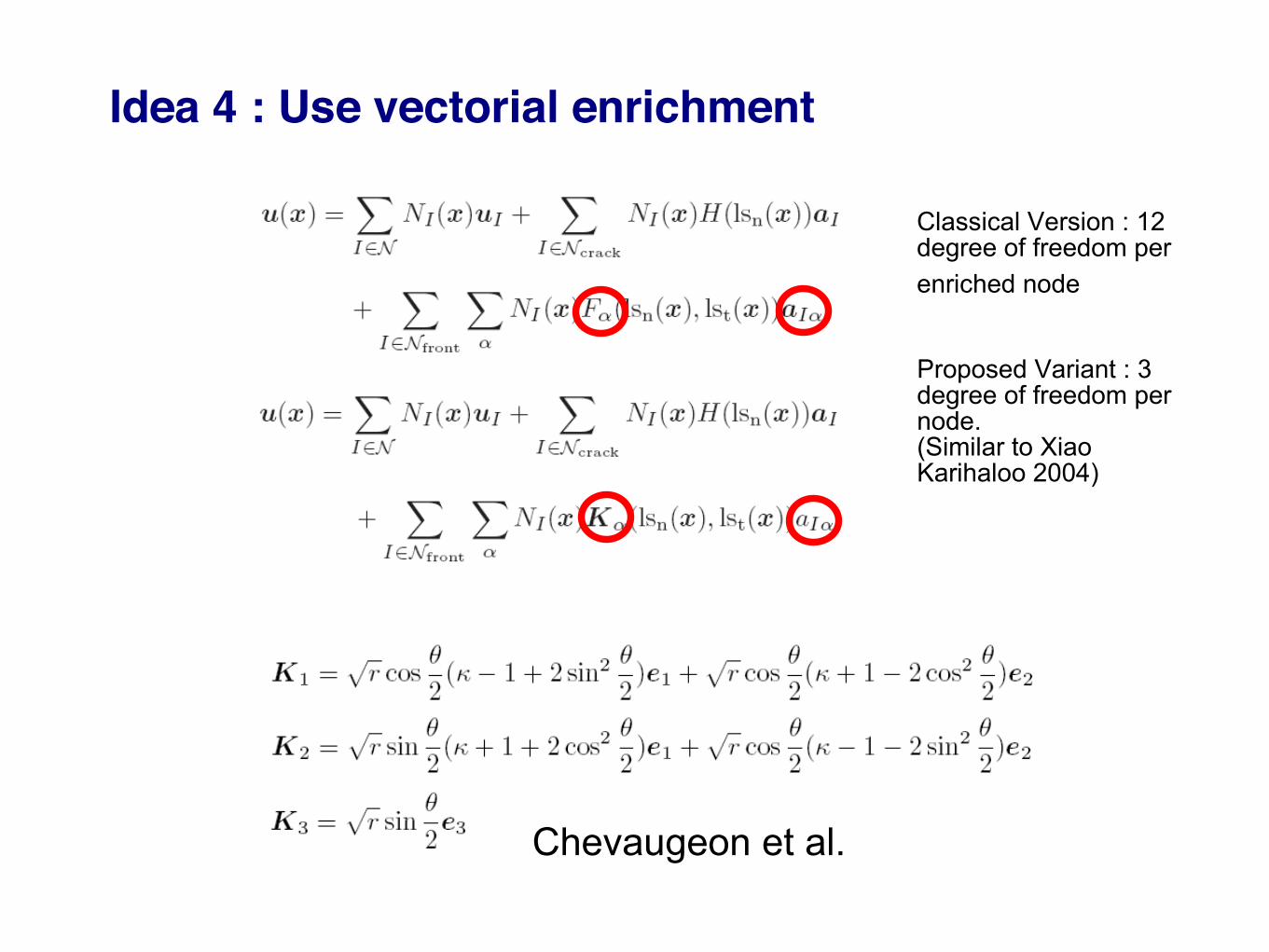
Idea 4 : Use vectorial enrichment
Classical Version : 12 degree of freedom per
enriched node
Proposed Variant : 3 degree of freedom per node. (Similar to Xiao Karihaloo 2004)
Chevaugeon et al.
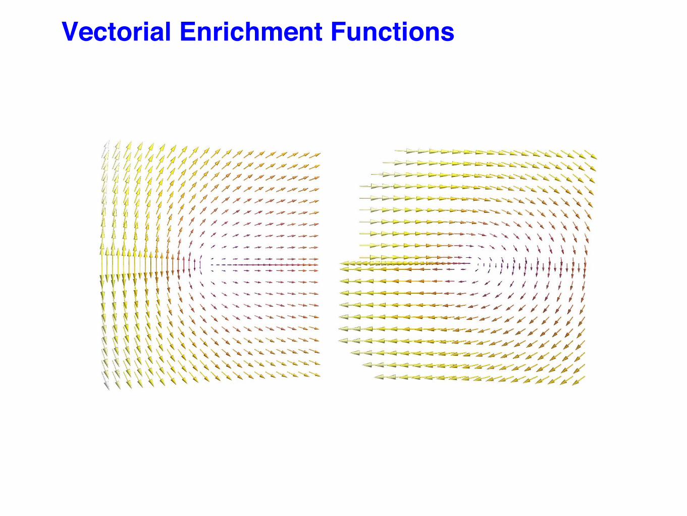
Vectorial Enrichment Functions

Classical enrichment functions

Conditioning
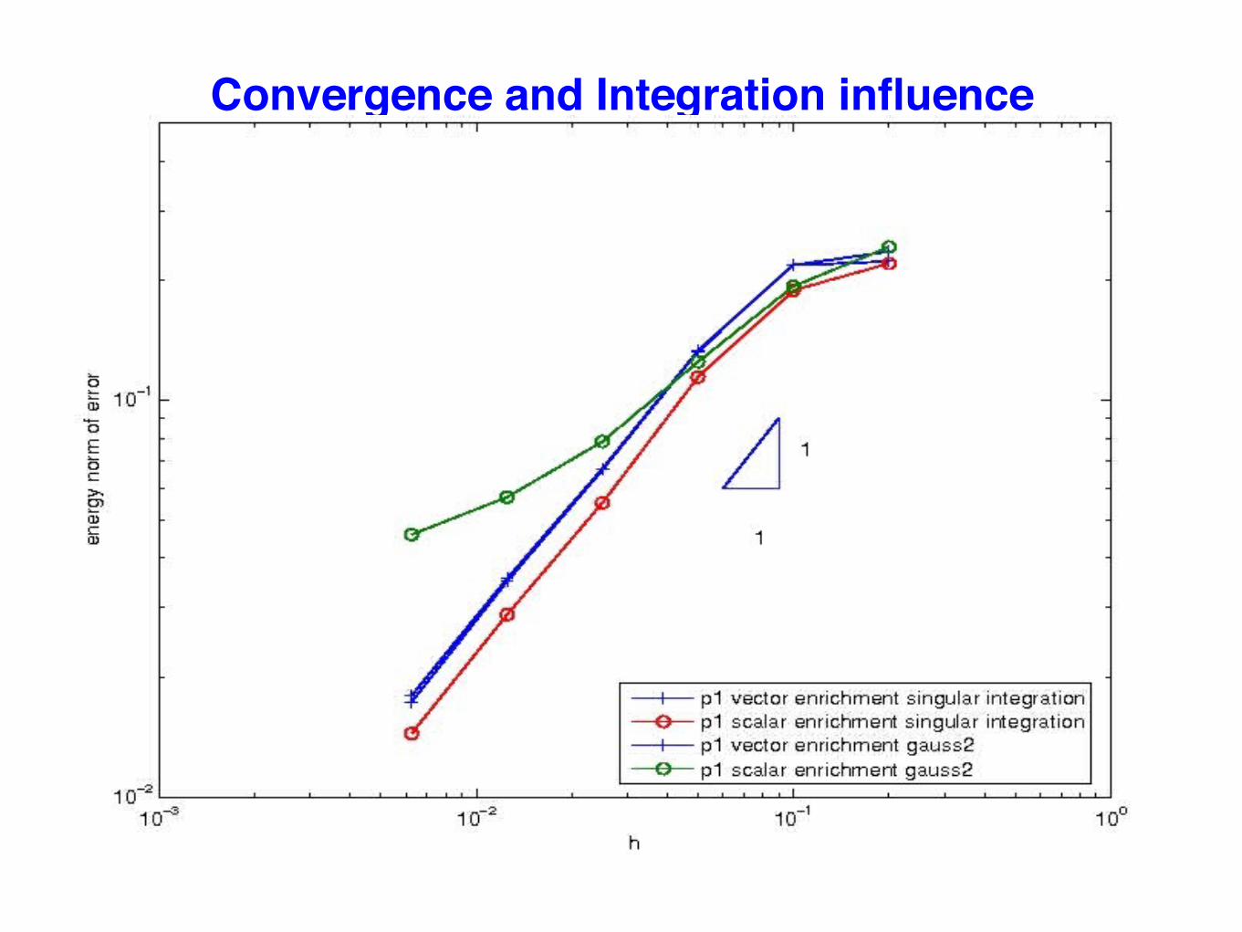
Convergence and Integration influence

Interplay between the ingredients.
Enrichment strategy
Integration rule
Convergence rateConditioning number

Circular Arc Crack Problem
(Bertram Broberg 1999)
Local level set basis is used to define the enrichment directions(Chevaugeon et al.)

Circular Arc Crack Problem
EXACT X-FEM

Circular Arc Crack Problem, convergence

Conclusion on The vector enrichment improvement
PRO:■ In 2D, 2 added dofs per enriched nodes instead of 4■ In 3D, 3 added dofs per enriched nodes instead of 12■ Good conditioning without any special treatment.■ Less sensible to integration rule accuracy.■ Same Convergence rate.
CONS:■ Error is slightly bigger.

Final comment on the enrichmentHigher order makes a difference
p=1
p=3p=2

p-version convergence results
Only the classical function are higher order, « optimal rate obtained » (Laborde et al. 05)

Direct evaluation of stress intensity factor ?
K1 enrichment coefficient field
K2 enrichment coefficient field
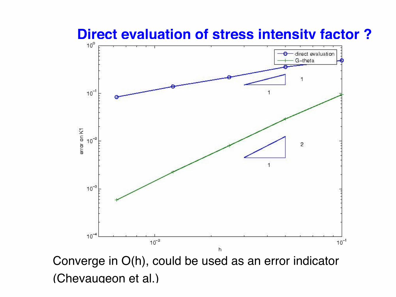
Direct evaluation of stress intensity factor ?
Converge in O(h), could be used as an error indicator (Chevaugeon et al.)

Evaluation of the stress intensity factors

■ Eshelby Tensor
■ J domain Integral :
■ Physical meaning :
■ Interaction integral based method to extract the SIFS. (G-Θ)■ Geometrical zone for the domain works best.
Stress Intensity factor computation 2D
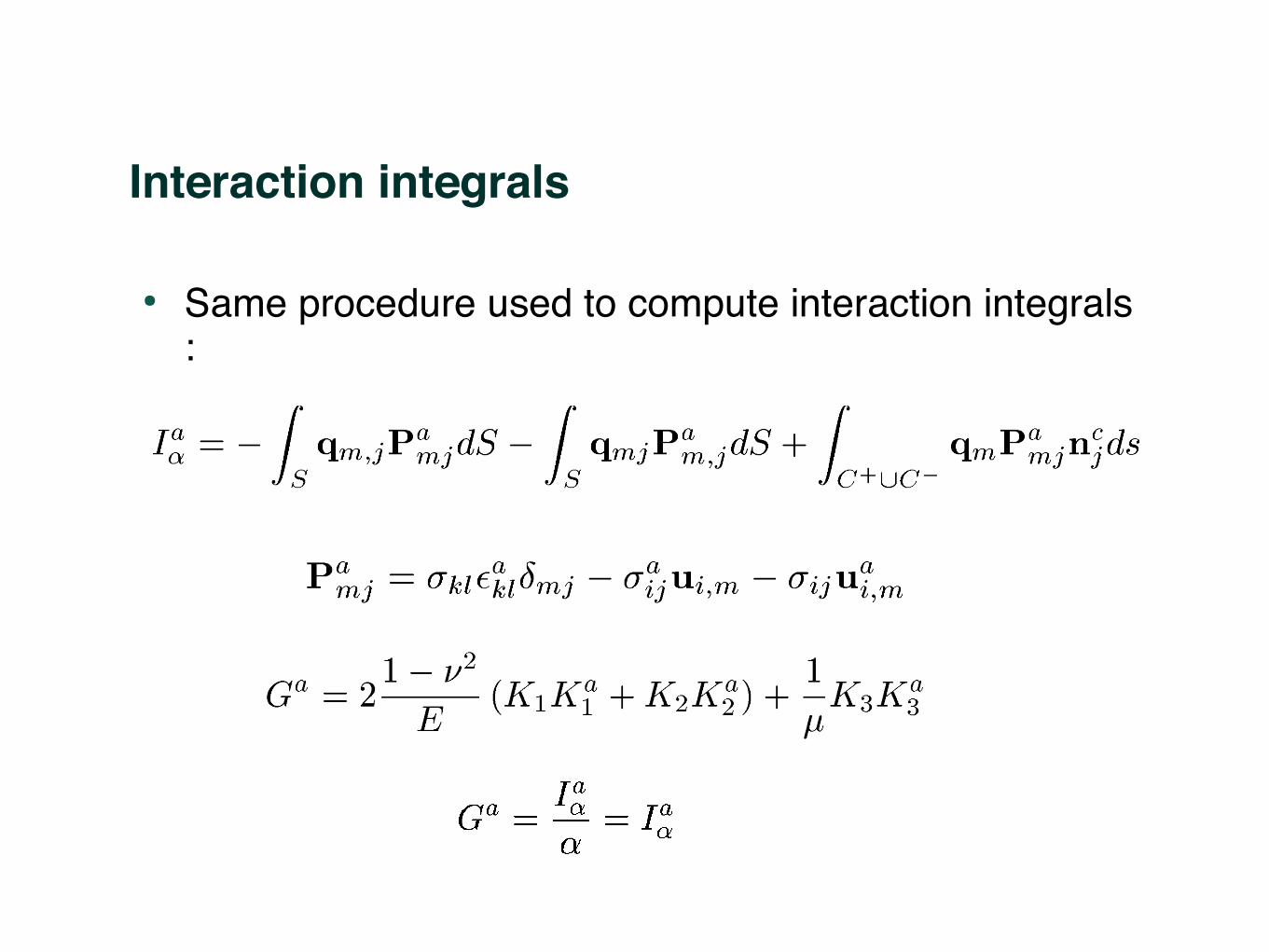
Interaction integrals
● Same procedure used to compute interaction integrals :
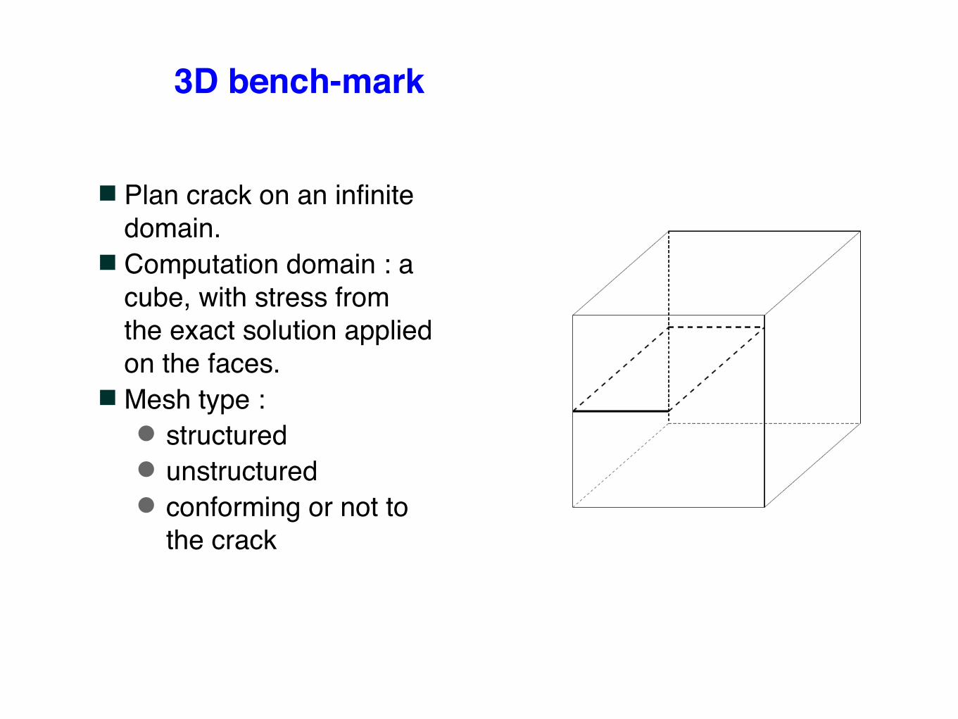
3D bench-mark
■ Plan crack on an infinite domain.
■ Computation domain : a cube, with stress from the exact solution applied on the faces.
■ Mesh type :● structured● unstructured● conforming or not to
the crack

Local Zone■ Good results on structured mesh.■ Oscillations on unstructured meshes.■ Computational time is high
Known Improvement in FEM :■ Build a finite element approximation of the stress intensity
factors field along the crack tip and solve a global problem. (Rajaram, Socrate, Parks 2000)
❖ Oscillations are still there, but can be filtered by using bigger elements.
❖ Implementation is difficult : Integration elements must be the intersection of the integration element for the X-FEM and the integration and the element defined for the approximation of the stress intensity factors.
Local Boxes method : Discussion
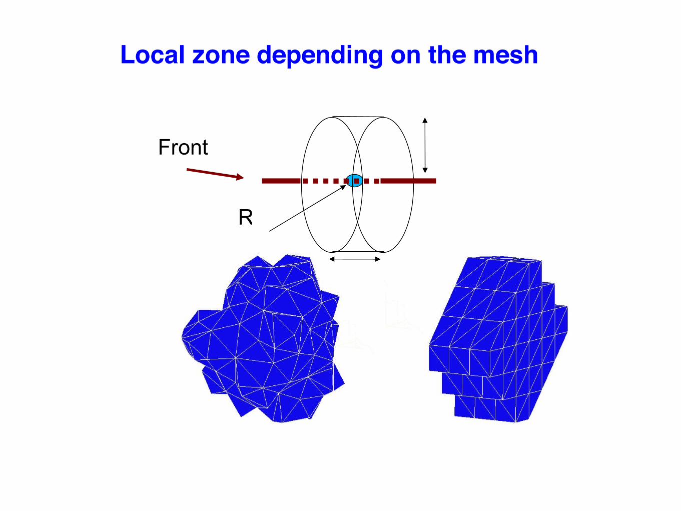
Local zone depending on the mesh
R
Front

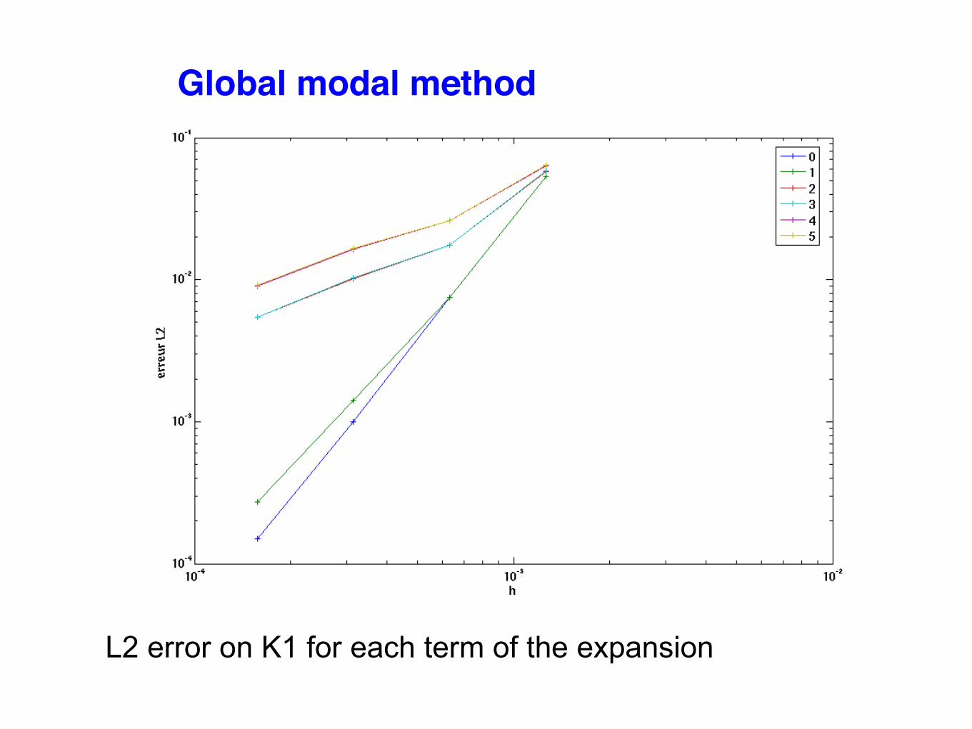
Global modal method
Proposed Improvement■ Instead of a finite element representation of the stress factor
intensity field, use a C infinite representation.● Advantage = integration is possible directly on the X-FEM
Integration mesh.■ The C infinite representation is written in terms of orthogonal
functions (Legendre or Fourier series for closed cracks).● The system to solve is diagonal.● Direct access to mean value and results are easy to filtrate.● Interpolation of the SIFS defined every where, no need for
extension step prior to a propagation algorithm.■ To further stabilise the result, a topological volume that tends
to zero with h is removed from the geometrical integration domain.

Global modal method (geometrical domain minus inner topological domain)
mesh nodes elements dofs

Global modal method
Global modal method
Convergence (K1-K1exact)2
L2 error on K1 for each term of the expansion

3D examples

Conclusion
DISCONTINUITY ENRICHMENTS■ It is important to master X-FEM AND it's alternatives.
VECTORIAL ENRICHMENT FOR THE FRONT■ Optimal order of convergence while maintaining immediate
good condition number (even for curved crack)■ Simplified integration rule possible (to be checked)
EVALUATION OF THE SIFS■ The global modal approach is the most promising■ no oscillations, good convergence■ easy to implement and fast■ velocity extension is not needed

Large deformations

φ
Large deformations
Legrain et al. 2004
Formulation lagrangienne totale

53
Comparaison with Abaqus on a DET
Abaqus conforming mesh X-FEM mesh

Comparison with Abaqus
Abaqus X-Fem
u

• Comparison with the results of Lake & Lindley

Deformed shape
Step 1 Step 4 Step 9 Step 15

Pure shear
Step 1
Step 4
Step 9
Step 15