x i--- cas file · nasa technical note! x i---z nasatn cas file d-7478 computer-aided space orbiter...
TRANSCRIPT
NASA TECHNICAL NOTE
!
XI---
Z
NASATN
CAS FILE
D-7478
COMPUTER-AIDED SPACE
ORBITER WING DESIGN
SHUTTLE
STUDY
by IV. Pelham Phillips, John P. Decker, Timothy R. Rau,
and C. R. G/art
Langley Research Center
Hampton, Va. 23665_°_ °¢ _o
12"76 ,_oj1¢o
NATIONAL AERONAUTICSAND SPACE ADMINISTRATION• WASHINGTON,D. C. • MAY 1974
https://ntrs.nasa.gov/search.jsp?R=19740014398 2019-02-03T20:53:44+00:00Z


1. Report No, 2. Government Accession No.
NASA TN D-7478
4. Title and Subtitle
COMPUTER-AIDED SPACE SHUTTLE ORBITERWING DESIGN STUDY
7. Author(s)
W. Pelham Phillips, John P. Decker, Timothy R. Rau,and C. R. Glatt
9. Performing Organization Name and Address
NASA Langley Research Center
Hampton, Va. 23665
12. Sponsoring Agency Name and Address
National Aeronautics and Space Administration
Washington, D.C. 20546
3. Recipient's Catalog No.
5. Report Date
May 1974
6. Performing Organization Code
8. Performing Organization Report No.
L-9099
10. Work Unit No.
502-37-01-01
'11, Contract or Grant No.
13. Type of Report and Period Covered
Technical Note
14. Sponsoring Agency Code
15. Supplementary Notes
C. R. Glair is associated with Aerophysics Research Corporation, Hampton, Va.
16. Abstract
An analytical and experimental investigation has been made to provide a space shuttle
orbiter wing design that met the guideline requirements of landing performance, stability,
and hypersonic trim for a specified center-of-gravity envelope. The analytical study was
facilitated by the use of the Optimal Design Integration system (ODIN) and the experimental
part of the investigation was conducted in the Langley low-turbulence pressure tunnel and
the Langley continuous-flow hypersonic tunnel.
17. Key Words (Suggested by Author(s))
Optimal Design Integration system (ODIN)
Space shuttle orbiter
Wing design study
18. Distribution Statement
Unclassified - Unlimited
STAR Category 31
19. Security Classif. (of this report} 20. Security Classif. (of this page) 21. No. of Pages 22. Price*
Unclassified Unclassified 84 $4. O0
For sale by the National Technical Information Service, Springfield, Virginia 22151


COMPUTER-AIDED SPACE SHUTTLE ORBITER
WING DESIGN STUDY
By W. Pelham Phillips, John P. Decker, Timothy R. Rau,
and C. R. Glatt*
Langley Research Center
SUMMARY
An analytical and experimental investigation has been made to define a space
shuttle orbiter wing configuration meeting the requirements for landing performance,
stability, and hypersonic trim for a specified center-of-gravity envelope. The analytical
part of the study was facilitated by the use of the Optimal Design Integration system
(ODIN). Limited experimental studies were made in the Langley low-turbulence pres-
sure tunnel and the Langley continuous-flow hypersonic tunnel to verify the aerodynamic
characteristics of the orbiter configuration selected analytically.
Use of the ODIN system greatly simplified the handling of analytical data while
maintaining compliance with the space shuttle general vehicle requirements and allowed
the expedient selection of a desirable wing planform. The analytical aerodynamic
estimates obtained by using the ODIN system were in reasonable agreement with experi-
mental results obtained subsequently for the orbiter configuration selected. The ana-
lytical study suggested reductions in wing sweep to produce a minimum-wing-area
(minimum-weight) configuration. Reductions in wing area and sweep also enhanced the
high-angle-of-attack trim capability at hypersonic speeds. This trend, however, was
constrained by entry heating considerations to preclude wing-leading-edge sweep angles
below 45 °. Hypersonic considerations of elevon size effects redirected the study toward
unsweeping the wing trailing edge to provide increased trimmed angle-of-attack capability
for a 46.8 ° swept-wing configuration which satisfied the guideline subsonic flight require-
ments. The analytically selected orbiter configuration required minor experimental
wind-tunnel refinements to provide a viable orbiter configuration. The primary refinement
*Aerophysics Research Corporation, Hampton, Va.

was the addition of a small planform fillet to increase lift coefficients at landing atti-
tudes. Significant reductions in lift-drag ratio losses due to the addition of attitude
control propulsion system wing-tip pods were attained by tailoring the external shape of
pods designed to house the roll-attitude control system. The use of sequentially deflected
segmented elevons improved subsonic trimmed lift-drag ratios which may be beneficial
to landing-approach glide-slope performance.
INTRODUC TION
As the space shuttle program has matured, significant effort has been devoted to
reductions in system weight resulting, in turn, in a smaller orbiter vehicle. The payload
weight and volume requirements remained fixed, however, and the variations in potential
payload centers of gravity exert an increased influence on the flight characteristics of the
smaller vehicle. In addition to wide center-of-gravity excursions due to the various
payloads, other interacting requirements such as a maximum allowable landing speed,
acceptable unaugmented low-speed flying qualities, and stable hypersonic trim at high
angles of attack present a formidable challenge to aerospace design.
Definition of a near-optimum design solution to these conflicting requirements
within a reasonable time frame requires the rapid examination of a large number of con-
figuration variables. Studies of means to automate design problems such as these have
resulted in the formulation of an Optimal Design Integration system (ODIN) described in
reference 1. The derived system is a unique approach to design synthesis in that it
allows interactive operation of existing analysis programs representing the various
problem-related technology areas. This paper presents the results of an initial utilization
of this approach.
In the present study an existing orbiter design with known weight characteristics
but unacceptable aerodynamic performance served as a baseline and the body, tail, and
internal arrangement were held constant. The ODIN system was utilized to determine
rapidly a wing configuration meeting the system requirements insofar as possible at a
minimum weight. The aerodynamic characteristics of the analytically derived configu-
ration were verified by experimental studies at subsonic and hyperscnic speeds.
Also included in the subsonic experimental studies were the effects of a wing leading-
edge planform fillet, wing twist, and the use of segmented elevons. The effects of wing-
tip-mounted attitude-control propulsion system pods were also determined at subsonic
speeds.

SYMBOLS
Values are given in both SI and U.S. Customary Units. The measurements and cal-
culationswere made in U.S. Customary Units.
A aspect ratio
6 mean aerodynamic chord, meters (ft)
C D drag coefficient, DragqooSref
C L lift coefficient, LiftqooSref
C m
Cmc L
CN
iwing
pitching-moment coefficient, Pitching momentq_oSref 6
aC m
staticlongitudinalstabilitylevel based on _, 0C----L-
normal-force coefficient, Normal f0r¢_qooSref
incidence angle of wing, deg
L/D lift-drag ratio
l length of fuselage, meters (ft)
M Mach number
qoo free-.stream dynamic pressure, newtons per meter 2 (lb/ft 2)
free-stream Reynolds number based on l
Selevon elevon area, meters 2 (ft 2)
Sref wing reference area, meters 2 (ft 2)
3
Vmin,des minimum flying speedat designconditions and ot = 17 °, knots
x,y coordinates of exposed reference wing planform (origin at exposed root chord
leading edge)
Xcg
Xwing
center-of-gravity location from nose of vehicle
location of exposed wing leading-edge root chord from nose of vehicle,
meters (ft)
XSF scale factor for x-ordinates of exposed wing planform
YSF scale factor for y-ordinates of exposed wing planform
Ot angle of attack, deg
5e elevon deflection angle, deg
?, taper ratio
Ale leading-edge sweep angle, deg
At e trailing-edge sweep angle, deg
Subscripts:
el,e2,e 3 inboard to outboard elevon segments
des design conditions
max mammum

min minimum
trim trim conditions
Abbreviations:
ACPS attitude control propulsion system
BWpV 2 body-plane (untwisted) wing-large vertical tail (subsonic model)
BWTV2F body-twisted wing-large vertical tail-fillet (subsonic model)
BWpV 1 body-plane (untwisted) wing-small vertical tail (hypersonic model)
Design P/L design payload condition (18 144 kg (40 000 lb) at payload bay centroid)
JSC NASA Johnson Space Center
Mod modified
ODIN Optimal Design Integration system
P1 semifaired ACPS tip pod design
P2 fully tailored ACPS tip pod design
P/L out payload-out condition
TPS thermal protection system
W 1 to W35 wing designations
W/40K PL with 18 144 kg (40 000 lb) payload at payload bay centroid
METHODOF ANALYSIS
An existing orbiter design, designatedthe 040A (ref. 2), of knownweight character-
istics with aerodynamicperformance characteristics unacceptablerelative to established
criteria, wasused as a baseline configuration. Thebody, vertical tail, andinternalarrangement were held constantandthe ODIN system wasutilized to determine a wing
geometry andlocation to meet the system requirements in the longitudinal mode. Useof
theODIN system allowed rapid perturbation of the orbiter wing geometry by directing the
sequentialexecutionanddata retrieval from a selectedgroup of analytical programs.The specific programs were chosento provide pertinent information representing the
technologyareas of subsonicandhypersonic aerodynamics, stability and control, weight,
balance, geometry, andgraphics.
Analysis Criteria
The guidelines establishedfor the wing design study (see table I) were in accord
with thoseoutlined and/or implied by the general vehicle requirements of the space shuttle
program. Theorbiter geometry and accompanyingweight statementusedas a study base-
line are indicated in table H and table III, respectively. The design criteria are furtherdepictedon the designenvelopeof payloadloadings for the orbiter shownin figure 1.
The requirement of a minimum designspeedof 150knots or less is shownfor an 18 144kg
(40000 lb) payloadlocated at the half-length station of the payloadbay. This payload
loading represents the maximum return payloadanticipated in its most forward location
in the payloadbay. Minimum design speed(Vmin,des) is usedherein to denotethelevel flying speedat _ = 17° and sea-level standardday conditionsfor an orbiter having
the designpayloadloading. Additional designcriteria included stable subsonicstaticmargin andhigh-angle-of-attack trim capability (O_max = 50 °) hypersonically over the
center-of-gravity range dictated by the payload envelope.
Parameters descriptive of these criteria, along with descriptive weights and
geometry data, were output in the ODIN summary reports for each wing design and are
included herein as an appendix. Pertinent information for the wings is summarized in the
appendix. These summary reports enabled the user to determine the wing having the most
desirable characteristics.
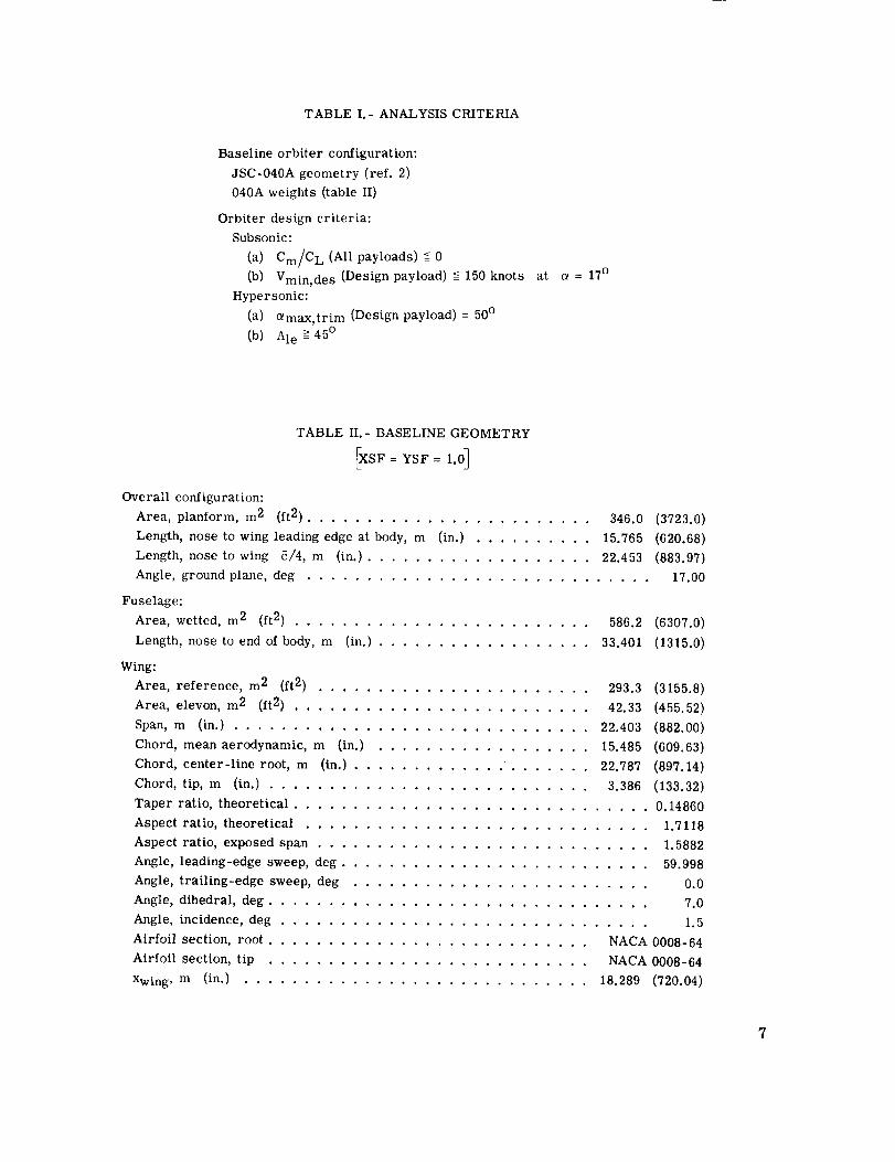
TABLE I.- ANALYSIS CRITERIA
Baseline orbiter configuration:
JSC-040A geometry (ref. 2)
040A weights (table II)
Orbiter design criteria:
Subsonic:
(a) Cm/C L (All payloads) <_-0
(b) Vmin, des (Design payload) < 150 knots
Hypersonic:
(a) _max, trim (Design payload) = 50°
(b) Ale -->45 °
at a = 17 °
TABLE II.- BASELINE GEOMETRY
fXSF= YSF= 1.0]
Overall configuration:
Area, plantorm, m 2 (It 2) ........................ 346.0
Length, nose to wing leading edge at body, m (in.) .......... 15.765
Length, nose to wing _/4, m (in.) ................... 22.453
Angle, ground plane, deg .............................
Fuselage:
Area, wetted, m 2 (ft 2) ......................... 586.2
Length, nose to end of body, m (in.) .................. 33.401
Wing:
Area, reference, m 2 (ft 2) ....................... 293.3
Area, elevon, m 2 (ft 2) ......................... 42.33
Span, m (in.) .............................. 22.403
Chord, mean aerodynamic, m (in.) .................. 15.485
Chord, center-line root, m (in.) ............. ....... 22.787
Chord, tip, m (in.) ........................... 3.386
(3723.0)
(620.68)
(883.97)
17.00
(6307.0)
(1315.0)
(3155.8)
(455.52)
(882.00)
(609.63)
(897.14)
(133.32)
Taper ratio, theoretical .............................. 0.14860
Aspect ratio, theoretical ............................. 1.7118
Aspect ratio, exposed span ............................ 1.5882
Angle, leading-edge sweep, deg .......................... 59.998
Angle, trailing-edge sweep, deg ......................... 0.0
Angle, dihedral, deg ................................ 7.0
Angle, incidence, deg ............................... 1.5
Airfoil section, root ........................... NACA 0008-64
Airfoil section, tip ........................... NACA 0008-64
Xwing, m (in.) ............................. 18.289 (720.04)

TABLEIII.- BASELINEWEIGHTSTATEMENT
Winggroup,kg (lb)............................ 6699.7(14704)Tail group,kg (lb) ............................. 1496.9(3300)Bodygroup,kg (lb)........................... 16391.1(36136)Inducedenvironmentalprotection,kg (lb) ............... 12265.7(27041)Landing,docking,recovery,kg (lb) .................... 4301.0(9482)Propulsion- ascent,kg (lb)...................... 10065.3 (22190)Propulsion- cruise,kg (lb)........................ 98.4 (217)Propulsion- auxiliary,kg (lb) ...................... 4140.9(9129)Primepower,kg (lb)............................ 1583.0(3490)Electricalconversionanddistribution,kg (lb) .............. 1285.9(2835)Hydraulicconversionanddistribution,kg (lb) .............. 440.0 (970)Surfacecontrols,kg (lb) .......................... 1183.9(2610)Avionics,kg (lb) .............................. 2501.6(5515)Environmentalcontrol,kg (lb)....................... 1397.1(3080)Personnelprovisions,kg (lb) ....................... 384.2(847}Growth/uncertainty,kg (lb) ....................... 5305.2(11696)
Dryweight,kg (lb) ........................... 69509.9(153242)Personnel,kg (lb) ............................. 714.4 (1575)Payload,kg (lb) ............................ 18143.8(40000)Residualandreservefluids,kg (lb) .................... 1376.2(3034)
Landingweight,kg (lb)......................... 89744.3 (197851)ACPSpropellant(entry),kg (lb) ...................... 3724.9(8212)
Entryweight,kg (lb) ........................... 93469.2 (206063)
80xlO3
41)
Payload, Ib
20
4O 000
llllllllHY
150-knotVmin,de s requirement
Payloadenvelope
' +Ascent loading
requirements
- 10 000
.4 .5
Forward Payload center of gravity/lpayloadstation
Figure 1.- Payload envelope depicting loading and flight requirements
for the space shuttle orbiter.
iEntry/landing
loadingrequirements
,1.6
3O 000
-20 000
Payload, kg
I I I --1 0
0 .I .2 .3

Method
The general programing arrangement within the ODIN system is shown in
figure 2(a), and the detailed programing arrangement for this problem is shown in
figure 2(b). After initialization, the geometry program calculated the geometric charac-
teristics of a matrix of wings selected as reasonable perturbations from the baseline
shape. This information was stored in the data base by the executive program DIALOG.
The calculations then proceeded sequentially for each wing geometry. The necessary
information needed to calculate wing weight was retrieved from the data base by utilizing
the DIALOG program which also input these values into the weight programs. Weights
were assigned to the fuselage structure, to the fuselage-contained components, and to the
vertical tail and were held constant during the study. The structural and the thermal
protection system weights of the wing were calculated by the methods described in
reference 3. This process was repeated through the balance program which calculated
the centers of gravity of the vehicle for the payload-in and payload-out conditions. The
INITIALIZATION 1
IGEOMETRY
SOMMAR¥R PORT. L
(a) General programing arrangement.
Figure 2.- Orbiter wing design problem formulation within the ODIN system.

IINITIALIZATION J
IGEOMETRYI
[BALANCEJ
ISUBSONIC AERODYNAMICS J
I HYPERSONIC AERODYNAMICS I_' ,,
IGRAPHICSlt
ISUMMARY REPORTJ
END
(b) Programing arrangement.
Figure 2.- Concluded.
static margins and trimmed C L were obtained from the subsonic aerodynamics program
(ref. 4). Static margins were obtained for payload-out and the design-payload conditions.
The payload-out static margin was weighed against a target static margin of 0.03_ + 0.002,
which assured longitudinal stability at the guideline subsonic flight conditions. If this
condition was not met, the system adjusted the longitudinal position of the wing and per-
formed an iterative looping back through the geometry, balance, and subsonic aerody-
namics programs until convergence was attained. After the final subsonic static margin
calculation, the hypersonic characteristics were calculated by using the methods outlined
in reference 5. The graphics program was then used to depict the vehicle and plot the
aerodynamic characteristics. A summary report provided the pertinent information such
as wing geometry, the weight of the vehicle, the center-of-gravity locations, the minimum
design speed, and the maximum hypersonic trim angle of attack and thereby completed the
design calculations for a specific wing.
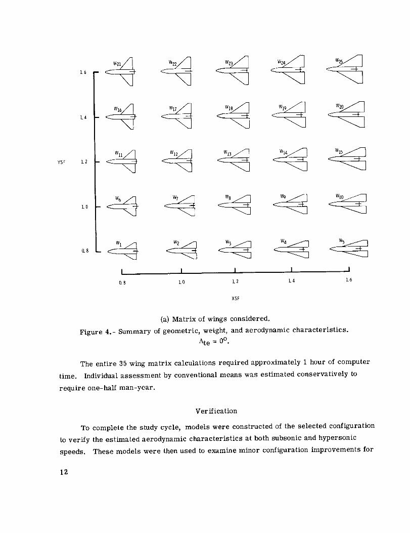
10

StudyVariables
The wing studyvariables were leading-edgesweepangle, aspect ratio, and exposedwing area. Theseparameters were varied by using x- andy-scale factors (XSF andYSF) to depict the exposedplanform of a study wing which is represented by the dashedout-
line in figure 3 (that is, a wing planform having XSF = 0.9 and YSF = 1.3 has exposed
root and tip chords equal to 0.9 times the exposed root and tip chords of the baseline wing
and an exposed span equal to 1.3 times the baseline exposed wing span). The trailing-
edge sweep angle was fixed (Ate = 0o) and the taper ratio of the exposed wing was held
constant for most of the study. To meet the subsonic static margin requirement, the
longitudinal wing position Xwing was varied. For some of the wings considered in this
study, Ate and Selevon were also varied. Twenty-five different wing planforms were
considered in the initial matrix which covered a broad spectrum of possible wing designs.
(See fig. 4(a).)
L_ Xwing
Ate
Selevon
\ I
t Baseline
/_ planform(y)(YSF) "--- j
SF- O.90 XS_-YSr-I._YSF- 1.3O
Figure 3.- Study variables.
The results of this matrix calculation were displayed in computer-generated maps
of combined design and performance data (figs. 4(b) to 4(d)) which enabled rapid isolation
of the effects of design variables. Based on the initial survey, 10 additional matrix points
were added to indicate the desired configuration more clearly.
11
YSF
LO
L4
1.2
1.0
0.8
I I
0.8 kO
---I-
I I I
1.2 L4 1.6
XSF
(a) Matrix of wings considered.
Figure 4.- Summary of geometric, weight, and aerodynamic characteristics.
Ate = 0o.
The entire 35 wing matrix calculations required approximately 1 hour of computer
time. Individual assessment by conventional means was estimated conservatively to
require one-half man-year.
Verification
To complete the study cycle, models were constructed of the selected configuration
to verify the estimated aerodynamic characteristics at both subsonic and hypersonic
speeds. These models were then used to examine minor configuration improvements for
12

Sref
92987kg 95255k_ Weight (Design P/L)t 6(2__05klb)(2]0 klb_97523kg (215klb)
1.41-\\\\, _ ,, (6500,21(200,klb)\\ -\\ \ \
ysF ].2L ?\\ "- \'k,5]]m288451kg_ 2
• 232m2., 32. m , 418m ,,(2500ilL) (3 }Off' (4500ftq
I I 1 I.8 1.0 1.2 1.4 1.6
XSF
(b) Sref and landed weight.
Ale
1 6 ,- //45_/ _ 160 °• /3.q,7 j5oo/55°/] s
[,Ao/ /,"YSF 1.21 ////_5 °
I I I _l__J.8 1.0 1.2 1.4 L6
XSF
(c) Ale and A.
YSF
(d)
1.6
1.4
1.2
1.0
.8
_- Vmin, des
----- amax,hyp
40_ 35° 30 °- \ \
_ _ __150knots-45_ _, _ \
,_" ', ll: kn°ts- 50 knots
- 55°_ \_ 200_ .._,...._,..__ knots
I I I I I.8 1.0 1.2 1.4 1.6
XSF
Vmin, des and Otmax, hy p.
Figure 4.- Concluded.
which analytical techniques are inadequate. The following section entitled "Apparatus and
Tests" is devoted to the introduction of the experimental aspects of the study.
APPARATUS AND TESTS
Subsonic
Model.- Details of the 0.01875-scale model used in the subsonic wind-tunnel design
verification investigation are shown in figure 5(a). The model incorporated the analytically
selected wing (W33 (Mod), table IV) mounted on a similarly scaled 040A fuselage. (See
ref. 2.) The model wing had a leading=edge sweep angle of 46.8 °, a trailing=edge sweep
13

_5 o
40.6B]
"-- (16.016)
_ c
62"63 :- 1: (2k.656)
(a) Subsonic model; BWTV 2 (0.01875 scale); Sre f = 0.11067 m2;
Ale = 46.8o; Ate = -11.0°; X = 0.135.
Figure 5.- Model schematic views. All dimensions are in centimeters (inches)
unless otherwise specified.
of -11.0 °, and an unswept elevon hingeline. The elevon tip chord was equal to 50 percent
of the local wing chord. The basic (unfilleted) wing had an NACA 0008-64 airfoil section
at the exposed root chord and varied linearly to an NACA 0012-64 section at the wing tip
chord. Two basic wings identical in projected planform were utilized: a plane (untwisted)
wing Wp with 1.5 ° incidence; and a twisted wing W T having the same incidence at the
exposed root chord and 4.5 ° washout. Trisegmented elevons were incorporated for the
model wings. A 60 ° swept planform fillet could be added ahead of the wing leading edge.
This fillet had a leading-edge radius of about 0.20 cm and a hand-faired section which
was tangential with the basic wing section at the local maximum thickness stations.
Addition of the wing fillet increased the exposed model wing area by about 8.5 percent.
14

TABLE IV.- SUMMARY DATA FOR SELECTED CONFIGURATION
_DIN summary data for W33 (MOd)_
Overall configuration:
Area, planform m 2 (ft 2) ..................................... 378.0 (4069.3)
Length, nose to wing leading edge at body, cm (in.) ....................... 1655.32 (651.70)
Length, nose to wing 6/4, cm (in.) ............................... 2267.71 (892.80)
Fuselage:
Area, wetted, m 2 (ft 2) ..................................... 585.9 (6307.0)
Length, nose to end of body, cm (in.} .............................. 3340.1 (1315.0)
Wing:
Area, theoretical or total, m 2 (ft 2) ............................... 314.67 (3387.1)
Area, elevon, m 2 (ft 2) ..................................... 63.06 (678.75)
Span, cm (in.) .......................................... 2756.9 (1085.4)
Chord, mean aerodynamic, cm (in.) ............................... 1362.76 (536.52)
Chord, center-line root, cm (in.) ................................ 2011.91 (792.09)
Chord, tip, cm (in.) ....................................... 270.92 (106.66)
Taper ratio, theoretical ........................................... 0.13465
Aspect ratio, theoretical .......................................... 2.4154
Aspect ratio, exposed span ......................................... 2.2896
Angle, leading-edge sweep, deg ....................................... 46.825
Angle, trailing-edge sweep, deg ...................................... -11.0
Angle, dihedral, deg ............................................ . 7.0
Angle, incidence, deg .............................................. 1.5
Airfoil section, root ......................................... NACA 0008-64
Airfoil section, tip ......................................... NACA 0008-64
Weight Xcg Xcg/l '
Mass properties at flight condition: kg (lb) m (ft) percent
Orbiter landing (Design P/L) ............. 90 541 (199 609) 21.7 (71.181) 64.96
Orbiter landing (P/L out) ............... 72 397 (159 609) 22.41 (73.523) 67.096
Wing weight ...................... 7473.80 (16 476.8)
Thermal protection system weight .......... 12 258.96 (27 926.2)
Principal parameters:
x-scale factor, XSF ............................................ 0.80000
y-scale factor, YSF ............................................ 1.3000
Distance to leading edge of exposed wing, Xwing, cm (in.) ................... 1655.31 (651.70)
Landing performance:
Minimum landing speed (Design P/L), knots ................................ 150.2
Static margin (subsonic) (Design P/L) ................................... 0.0804
Static margin (subsonic) (P/L out) ..................................... 0.0280
Trim C L for landing (a = 17 ° ) ...................................... 0.7715
Hypersonic aerodynamic trim data:
Trim angle of attack at elevon -45 °, deg .................................. 45.59
15

The vertical tail V2 (ref. 2) had NACA 0012-64 airfoil sections. Semilaired and fully
tailored wing-tip-mounted ACPS pods were included as model configuration variables
Pl and P2' respectively. These pods were sized to represent the scaled volumetric
requirement of the ACPS roll control. (See fig. 5(b).)
Semifairedpods,P1Volume(2pods)• 31.0 cm3
Fully tailoredpods,P2Volume(2pods)- 31.0cm3
(b) Wing tip roll ACPS pods (0.01875-scale model).
Figure 5.- Continued.
Tunnel.- Subsonic tests were conducted in the Langley low turbulence pressure
tunnel which is a variable-pressure, single-return facility with a closed test section
0.914 meter (3.0 feet) wide and 2.29 meters (7.5 feet) high. The tunnel is a low subsonic
facility (M < 0.4) with the capability of Reynolds numbers per unit length up to about
49.2 X 10⁶ per meter (15.0 × 10⁶ per foot).
16

Test conditions.- The investigation was conducted at a Mach number of about 0.25
and at Reynolds numbers from about 12.6 × 10⁶ to 21.0 × 10⁶, based on the fuselage length.
Test angle of attack was varied from approximately -3 ° to 20 ° at 0 ° sideslip.
Measurements and corrections.- An internally mounted six-component strain-gage
balance was used to measure aerodynamic forces and moments acting on the model. No
base- or chamber-pressure corrections were applied to the data. Corrections have been
applied to the angles of attack and sideslip to account for sting and balance deflections
produced by aerodynamic load on the model. All pitching-moment coefficient data are
presented about the moment reference point location shown in figure 5(a) unless otherwise
specified. The subsonic longitudinal aerodynamic coefficients and angles of attack have
been corrected for blockage and lift interference in accordance with the techniques out-
lined in references 6 and 7.
Hypersonic
Model.- The hypersonic model was a 0.0075-scale model of the analytically selected
configuration and is shown in figure 5(c). The model wing geometric features were simi-
lar to the subsonic plane (untwisted) model wing. The vertical tail V 1 was geometrically
similar in planform to the 040A vertical tail V 1 (ref. 2) and used NACA 0012-64 airfoil
sections.
Tunnel.- The hypersonic tests were made in the Langley continuous-flow hypersonic
tunnel, which is designed to operate over a pressure range of 15 to 150 atmospheres
(1 atmosphere = 101 325 N/m 2) at temperatures up to 1090 K (1960 ° R). Air is heated
by an electrical resistance multitube heater prior to entry into a water-cooled contoured
nozzle which has a 79-cm-square (31-inch-square) test section. Continuous operation
is achieved by recirculating the air flow through a series of compressors. Reynolds
number varies from 1.64 × 10⁶ to 8.53 × 10⁶ per meter (0.5 × 10⁶ to 2.6 × 10⁶ per foot).
Test conditions.- The hypersonic tests were conducted at a Mach numuer of about
10.3, a stagnation pressure of about 50 atmospheres, and a test Reynolds number of about
0.8 × 10⁶ based on the fuselage length. Data were taken at angles of attack from approxi-
mately 15 ° to 48 ° at 0° sideslip.
Measurements and corrections.- Aerodynamic force and moment data were meas-
ured by an internally mounted six-component strain-gage balance. The balance was strut
mounted on an injection system assembly which inserted the model into the airstream.
17

6. 887(?..711)
k20.677
(8. 140)
1,.
16,2-/2 45°_/-__: - (6. 406)
25.051 _ I_' (9. 802)
(c) Hypersonic model; BWpV 1 (0.0075 scale); Sre f = 0.1771 m2;
A1 e =46.8°; Ate= -11.0°; _=0.135.
Figure 5.- Concluded.
Balance temperatures were continuously monitored to allow model retraction prior to
overheating of the components. Angles of attack have been corrected to account for sting
and balance deflections produced by aerodynamic loading. No base- or chamber-pressure
corrections were applied to the data. The pitching-moment coefficient data are presented
about the moment reference point location shown in figure 5(c).
RESULTS AND DISCUSSION
Analytical Results
Effect of wing geometry on aerodynamics t weight, and performance.- Summary
results from the initial 25-wing matrix (Ate = 0°) are shown in figure 4 and in the appendix.
18

The resulting configuration geometries, curves of constant landed weight, wing reference
area, aspect ratio, leading-edge sweep, minimum design speed, and maximum hypersonic
trim angle of attack are presented in figure 4. In order to satisfy the guidelines of the
study, a wing is required to have the geometry specified at or above and to the left of the
intersection of the 150-knot Vmin, des curve with the curve for a hypersonic trimmed
_max of 50 ° . This projected intersection would occur at values of XSF and YSF of
about 0.75 and 1.4, respectively, which represents an A > 3.0 wing configuration having
a leading-edge-sweep angle less than 450. (See fig. 4(b).) Entry heating considerations,
however, which were used to establish the 45 ° minimum wing sweep boundary of table I
precluded the further consideration of the aerodynamically desirable wing configurations
indicated in figure 4. The nearby region containing wings having leading-edge sweep
angles of 45 ° or greater was then investigated since it should contain the wing configu-
rations most nearly conforming with the established guidelines and constraints. For this
purpose 10 additional wing configurations were added to the initial matrix. Summary data
for these additional configurations are presented in the appendix.
Effect of elevon size and Ale.- Figure 6 shows the effect of elevon chord increases
on the hypersonic trim capability of the orbiter wings included in the study matrix. These
results indicate that increasing the elevon area by about 4 percent of the wing area
increases the maximum hypersonic trim angle from 6 ° to 8° for wings having reference
areas between 210 and 330 m 2 (2260 and 3552 ft2). Figure 7 shows the effect of leading-
edge sweep angle on the subsonic minimum design speed. The lower sweep angles allow
the smaller wing areas to meet the subsonic requirement for a minimum design speed of
150 knots. In addition, reduced wing areas yield increased hypersonic trim angle-of-
attack capability as indicated in figure 6.
Configuration selection.- Two configurations W27 and W33 (see appendix) were
selected from the study matrix for further analysis. These configurations exhibited
values of XSF and YSF indicated in figure 4 and would most likely result in wing plan-
forms capable of meeting the subsonic-hypersonic criteria without violating the 450 mini-
mum sweep constraint. The configuration W27 is defined in the appendix for values of
XSF and YSF of 0.9 and l.3 and configurationW33 by XSF and YSF values of 0.8
and 1.3. These two configurations were selected since each was considered to be margin-
ally acceptable in satisfying the guidelines of the study regarding hypersonic trim and
minimum design speed. As indicated in the index in the appendix (table V), Vmin, des
for W27 and W33 were 151 knots and 154 knots, respectively. Also indicated are maximum
19

Sr_, ft 2
4000
3200
2800
240O
ZOO0
Ir ........_J
:H.H;ffL_,I i:_i
Regionof interest
!ti_it_titli::_0 lO 20 30 40 50
amax, trim (Design payload),deg
:m 375!ii
._i_350
:_: ;
'-7T:
-_-_
:IL
70
Figure 6.- Analytical effects of elevon size at hypersonic speeds
for study wings. Ate = 0 °.
_5
Sr_, m2
275
2_
_5
2_
Sr_, ft_ HH3200 _
2400_-_,__
130 140
...... i, ,, ,i
__ 375
__]I_ _'' m2___ Sr_'
!.__ ._ 27.5
_I Ale _l_iil_!_
t_ _ z25
150 160 170 180
Vmin, des (Design payload),knots
Figure 7.- Analytical effect of leading-edge sweep angle.
2O

hypersonic trim angles of 40 ° and 46 ° , respectively, for the two configurations. At this
point in the design cycle, improvements in the analytical aerodynamic characteristics
as well as the introduction of empirical or experience factors are required to insure
experimental compliance of the selected configurations with the established aerodynamic
guidelines. For example, past comparisons with experiment have indicated higher ana-
lytical values of subsonic CL and hypersonic trim capability (ref. 8) than experimental
results for delta wings of moderate aspect ratio and sweep.
Reduction of Vmin, de s to the 150-knot guideline value requires an increase in
wing area for both configurations (W27 and W33); hypersonic trim requirements, on the
other hand, dictated a decrease in wing area or that the wing be moved forward to reduce
the level of longitudinal stability. The subsonic stability criteria constrained the forward
wing movement for both wings and thereby precluded meeting the hypersonic trim
guidelines.
A possible solution to these conflicting requirements would be to increase the wing
area slightly by using a negatively swept trailing edge and move the wing forward to
comply with subsonic stability requirements and to achieve increased hypersonic trim
capability. Additional benefits in hypersonic trim might also be realized by retaining the
present elevon hingeline locations relative to the exposed wing to provide increased
movable elevon areas. The effects of these modifications on wings W27 and W33 are'
shown in figures 8 and 9, respectively. Analytical results for the W27 modification
indicate that the target Vmin, des of 150 knots was achieved, whereas the hypersonic
°_nax, trim increased by only lO to a value of 41 o. Since the wing-forward movement
was very slight, the corresponding increase in hypersonic trim angle was extremely small.
(Compare fig. 8(a) with fig. 8(b).) Comparison of figure 9(a) with figure 9(b) shows that
these modifications of W33 produced more desirable results. The value of Vmin, des
for the modified wing was reduced to 150 knots whereas hypersonic trim capability was
extended to 49 ° . This wing configuration was selected for the experimental verification
with one further modification; the elevon chords were arbitrarily reduced to improve
structural integrity of the wing tips. The resulting configuration selected is shown in
figure 10 and pertinent summary characteristics are shown in table IV. The analytical
results indicated that the selected configuration met all the aerodynamic design require-
ments outlined in table I with the exception of the maximum angle-of-attack hypersonic
trim. Because of the reduced elevon area, the design exhibited a maximum trimmed
angle of attack 4° less than the required value (50o). This deficiency could be eliminated
21

XwingL.
Selevon- 49.5 m2(533ft2)
: 16.0m (52.5ft)
(a) Ate = 0°; W27; Vmin, des (Design P/L) = 151 knots;
hypersonic amax, trim (Design P/L) = 40°;
Sre f = 312 m 2 (3357 ft2).
Selevon- 60.1m2
(647ft2)
(b) Ate = -7.00; W27 (Mod); Vmin, des (Design P/L) = 150 knots;
hypersonic Otmax, trim (Design P/L) = 41°; Sre f = 328 m 2 (3535 ft2).
Figure 8.- Effect of trailing-edge sweep angle on wing W27. Ale = 50.2 °.
by some fuselage nose reshaping (not considered in the wing study) which has been shown
to provide a positive increment in pitching moment. (See ref. 9.)
Subsequent experimental wind-tunnel studies using the selected configuration were
made to validate these aerodynamic estimates and to demonstrate the aerodynamic develop-
ment required to produce a satisfactory orbiter design.
Experimental Results
The basic longitudinal aerodynamic data obtained at subsonic and hypersonic speeds
for the selected configuration are presented. The subsonic data are shown in figures 11
22
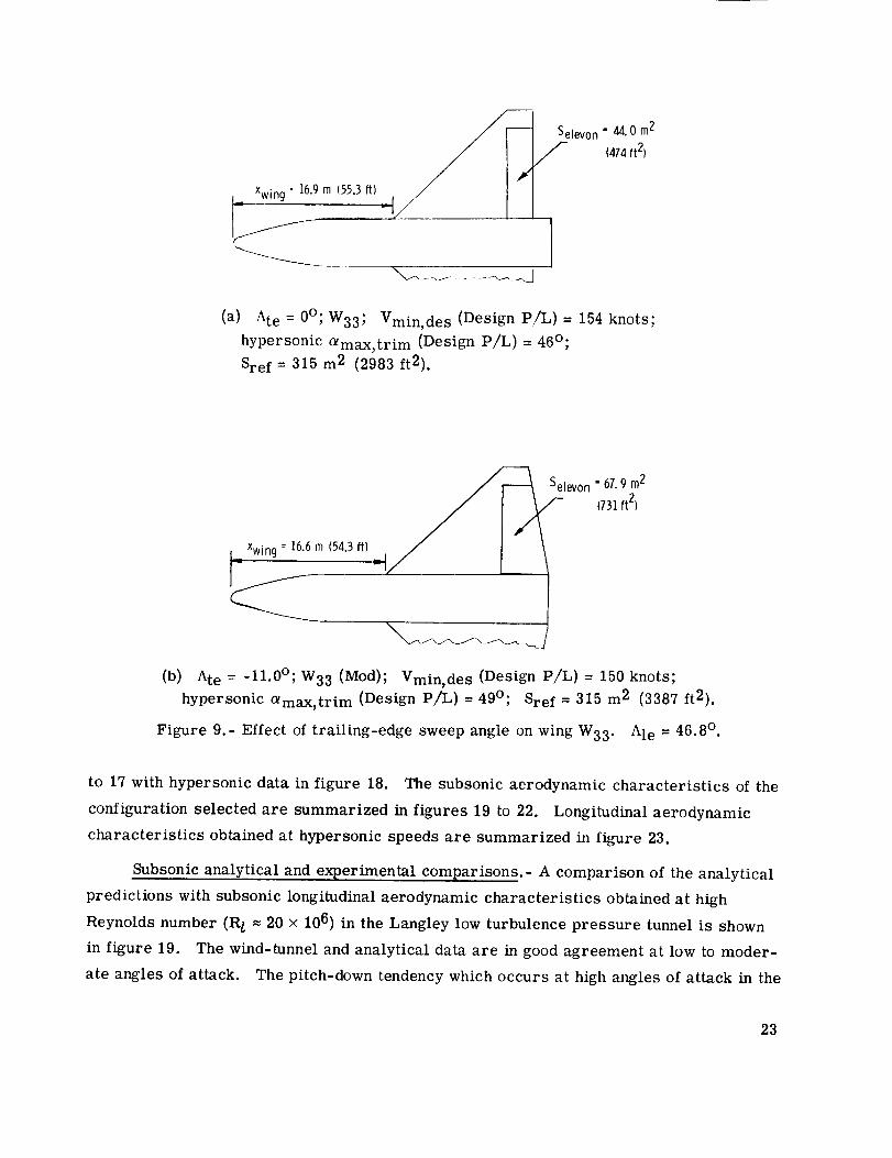
X_wing = 16.9m (55.3ft)
levon " 44.0 m2
(474 ft2)
(a) Ate = 0°; W33; Vmin, des (Design P/L) = 154 knots;
hypersonic emax, trim (Design P/L) = 46o;
Sre f = 315 m 2 (2983 ft2).
L_ Xwincj= 16.6 m (54.3if)
• 57.9 m2
_=._ levon (731 ft2)
(b) Ate = -11.0°; W33 (Mod); Vmin, de s (Design P/%) = 150 knots;
hypersonic Otmax, trim (Design P/L) = 49o; Sre f = 315 m 2 (3387 ft2).
Figure 9.- Effect of trailing-edge sweep angle on wing W33. Ale = 46.8 °.
to 17 with hypersonic data in figure 18. The subsonic aerodynamic characteristics of the
configuration selected are summarized in figures 19 to 22. Longitudinal aerodynamic
characteristics obtained at hypersonic speeds are summarized in figure 23.
Subsonic analytical and experimental comparisons.- A comparison of the analytical
predictions with subsonic longitudinal aerodynamic characteristics obtained at high
Reynolds number (R/ = 20 × 106) in the Langley low turbulence pressure tunnel is shown
in figure 19. The wind-tunnel and analytical data are in good agreement at low to moder-
ate angles of attack. The pitch-down tendency which occurs at high angles of attack in the
23
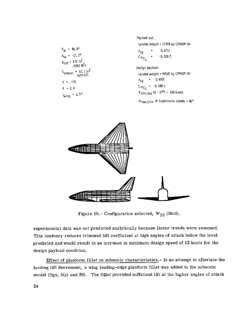
Ale - 46.8°
Ate - -11. 2°
Sref = 315 m2(3381ft2)
Selevon - 63. I rn2(679ft21
;_ - . 135
A -2.4
iwing • 1.5°
Payloadout:
Landedweight • 72398kg (159609Ib)
Xcg O.6711.
CmcL - -0. 028
Designpayload:
Landedweight - 90542kg (199609Ib)
Xcg O.650/.
Cmc L -0. 080c
Vmin,des (o[= 17°) = 150knots
amax,trim at hypersonic speeds- 46:
Figure I0.- Configuration selected, W33 (Mod).
experimental data was not predicted analytically because linear trends were assumed.
This tendency reduces trimmed lift coefficient at high angles of attack below the level
predicted and would result in an increase in minimum design speed of 12 knots for the
design payload condition.
Effect of planform fillet on subsonic characteristics.- In an attempt to alleviate the
landing lift decrement, a wing leading-edge planform fillet was added to the subsonic
model (figs. 5(a) and 20). The fillet provided sufficient lift at the higher angles of attack
24

24
2O
16
_2
8
4
a,deg 0
-4
.12
08
.04
0
Crn
-04
-.08
-.12-4 -.3 --,2 --.I 0 .I ,2 o_ ,4 ,5 .6 .7 ,B .9
CL
Figure 11.- Effect of Reynolds number on the longitudinal aerodynamic characteristics
of the untwisted wing configuration BWpV 2. 5el = 5e2 = 5e3 = -10 °
to linearize the trimmed lift curve and provide a minimum design speed of about 150 knots.
The addition of the fillet shifted the aerodynamic center of the configuration about 0.05_
forward and required a rearward shift of the wing of about the same amount to keep the
static margin of the configuration (payload out) at 0.03_.
25

LID
CD
I0
i '
4
Figure 11.- Concluded.
26

a ,deg
0
Cm
-04
- .08
-.12-.4 .8 .9
C L
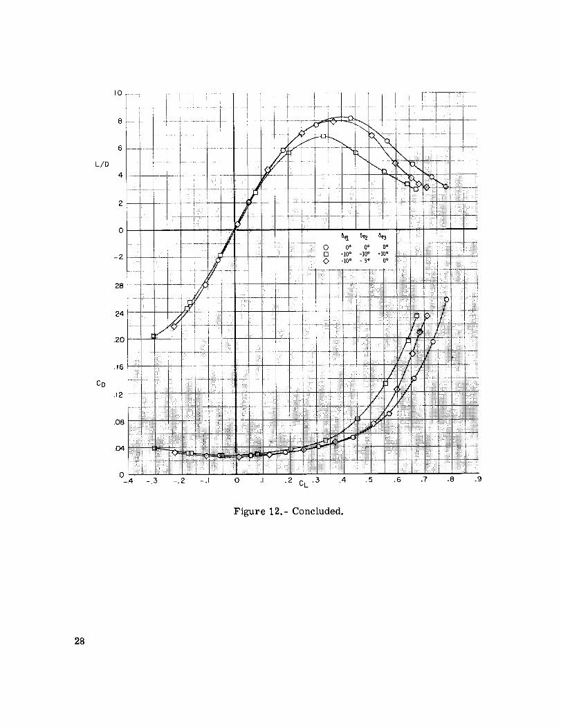
Figure 12.- Comparative longitudinal trim effects of unsegmented and segmented
elevons for the untwisted wing configuration BWl}V 2. R1 = 20.1 × 10⁶.
27
LID
I0
-2
,28
.24
.2O
CD
,6 iiiiii! ,iii:++¸i+_+i+++,_++
• I _ :Z!! !!IL-, i_:i:i::i
.08
.04
0-.4 -.5 -.2
iiii_+i+_ _i,i_i+_ i!!!+i_+:i!#::]iiiiiil_:_iiili_i!_i_iiii!!i!
-.I 0 .i .2 Ci_'5 .4 .5 .6
_ :!i! ..... !!:b" i]:iii:
ilii _ i_ii!!iil _i _il ii _
!!iii!:i :i::ii::: :_iiiil] }i];!i!im:;:::q ::I::;:: :::_:_::_ ::::m: _:::_
iiiiiii+!!iiiii!iii!iiiil
_!i!i _-_ ii!!!_!i _ iiiiiii!i_ iiiii_ _ _.......
.7 .8
iiii[i_
:::]]]ii
E_I]]]II:::::m:
!]:Hi!:!
i!::iiiil:; m;:
:iiii[!!i
;;i;[ii;[:
i!!i!i:
.9
Figure 12.- Concluded.
28

24
2O
16
12
!]iiiiiil[!!ii!_li::iiHi
4
,deg 0
h;=: '_!!fiil ; L: :i!i L ; !i
-4 0 OFF -10" -10" -10" ................... ::.,_::, .... r, PION -1o° -lO. -10":- :::::" : : i;m::
. L::::.:..: :ii_ _|iL _ ,:_iL_ _ !i_::..::l iL : !_:: :_ilLii:_Lli:::.Aii_ ...............
.,2 , , I i l:
.O8
.O4
0
Cm
-.04
-.08
i!i!ii!ifl
ii:!i._-.I 2 -.4 -.5 -.2 -.I 0 .I . 2 • 3 .4 • 5 .6 .7 .8 .9
CL
Figure 13.- Effect of adding ACPS pods P1 on the aerodynamic characteristics of the
untwisted wing configuration BWpV 2. R l = 20.0 × 10⁶.
29

L/D
CD
Figure 13.- Concluded.
C L
.5 .6 .7 ,8 .9
3O
a ,deg
12
........ +.......
i i :' I::I_ i!:i
i ..... _!I, ! !!:::: : x:::
+ ....
:: t +++
"++++ii+++i+i+++++i+!i:_ii!iil _:I_!i!i_:!i?::ii:i:ii!iiliii!_,_:,_
ii;; :!:! i::;21112:11;::22_!iiiiZSiiil[i!:iil _:aaa_
:i iii :i iiiii : i i!:: ::.:: :;::; ::: ::
::::xx: :: :
a
:: ::: .... ::::;: ;:::: ...............
::::: ilrHilri i1!21!2
xx:: :::; xxm:: x:;i:
::-::ii! ih_ i_! !!i_J,i!
iiiii!i; i?iiiiiiiiiiii!i iii!iliiiiiii:i ::_ii!i iiiiiii! ii!igii
::_i :::iii ii!iiiii s!ii!il• :!: 21i iii:i[i ::filial
::: :.x :x::: ::x:l:
............... ::;{iI:; :;;v .:
:1::: xxxx-:::_:_ xxx...... :xm:: :::xm :m:
1111 :i:![i k;_::_il ;:12![
x:::::: x ::;; i; +++++++++:+:+_:++:+: :: :xx: :x:::; x+
.................. x: :
i[i)i;iiiii)ii!iii;;ii;ii: iiii!!i(::::::::,:,::iiiii:_ii}iiiiiiiii_:
........ .......4_c
++++++.......++++++++
i};!;iiiiiii!iiil........!i
............... iiii!!iim;:" rrr::--11;i1112
:::iii H ...............:::::_x _111!!_i !_!111iii_!_i!H :i:!ii!: :::?!iii
:;::::I: ;;::;m ::::::::
.7 .8
!iiiii
++:.:=.:=
iiiii!_i?
ii:: !!
!ill: :
+::iii!:i
:::x;:x
_+1-+
:_iiii!_!ii:!iiii::::_i
11111;:
::!1!11
.._4J;i]
IE[E_::x:::::
::::!iii
i!!!! ?_
:iii i?:
::ii111:::xxl:::::xx:-::x::
.9
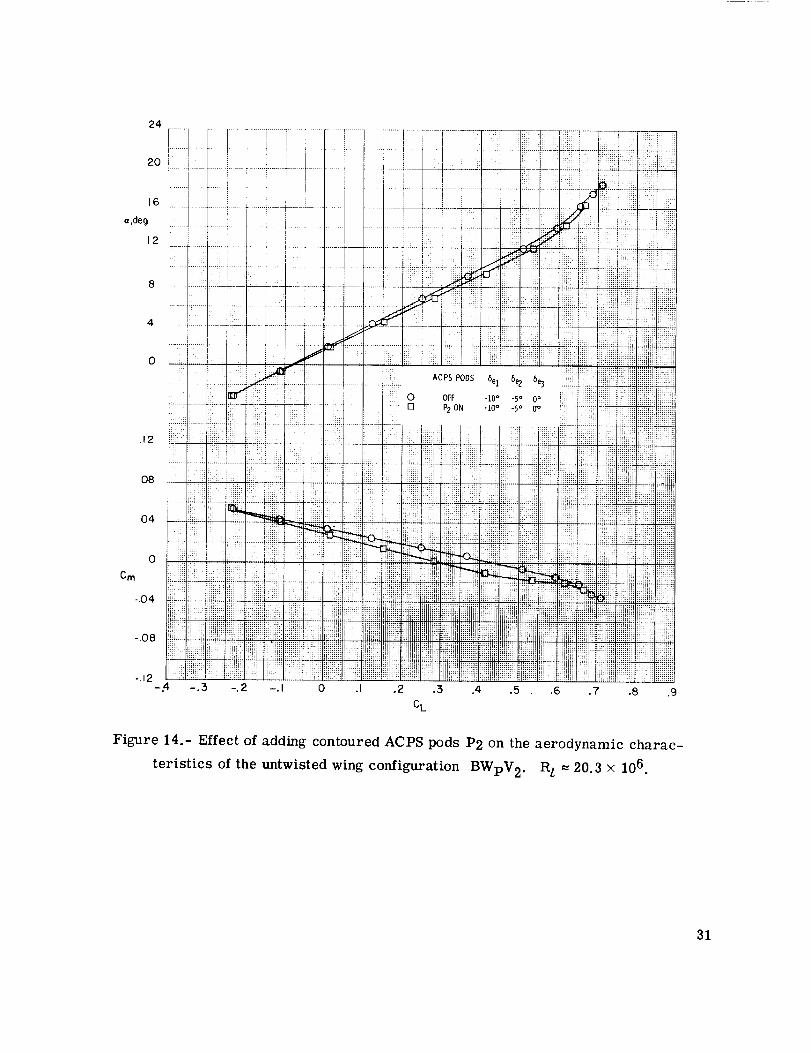
Figure 14.- Effect of adding contoured ACPS pods P2 on the aerodynamic charac-
teristics of the untwisted wing configuration BWpV2. R l = 20.3 x 10⁶.
31
IO • -
!i
6
L/D
4
-2
24
16
CD2
O8
04
-.3 -.2 -.I 0 .I .2 .3 .4 .5 .6 .7 .8 .9CL
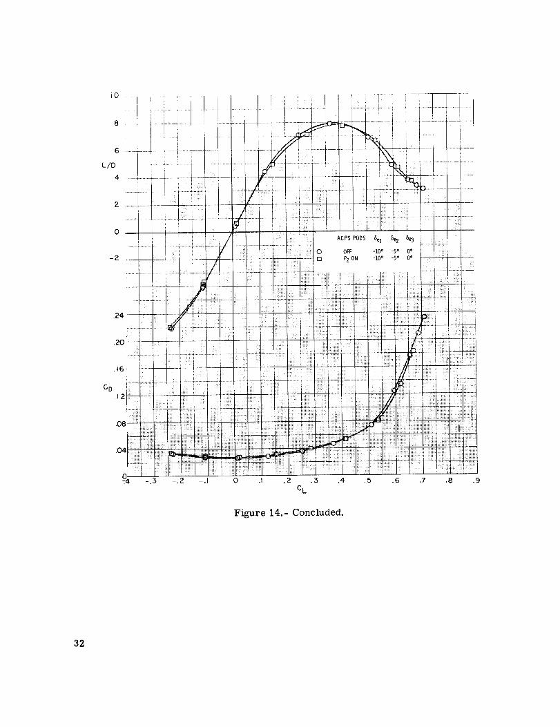
Figure 14.- Concluded.
32
24
16
a ,deg
Cm
]iiii!!!iiii
i:_ • !!!!!:_iiiiiiii! _:!:_:_ii!:iil :i:; i:iil ii:_ii!_ ::ii_iill::¸
...... _.:;--.-_-1---;-- : : : -_i _i_.L'
: :: : .... : It
..... :::l;lllill;
_! _ !!:_:: i::i!ii!
.... :::: :::: :]i! ....
::ili ii:: ii$/i ii_i :,,;i_i¢ !!:#C',;I
!:: -10o - 50 0o ::i:iill
i[ i: ii ili:.i_;:i;: i'_i;_:ii;:: ::;:: ::i i_i:i:iL.£:!_ :_!_iii_:
:::,: . ;ii!ii_i¢_.::!: :::_'_
:::.... _!!!i
'i!i ....!_!!!::i '_'
i!!ii lilttlt!!tiililIiiiil IIltiN_' !l ifilii!i_ ':::: ,H_::_,_NIIIlI!i!¢H!I!_ii':!liltttIII!:!ii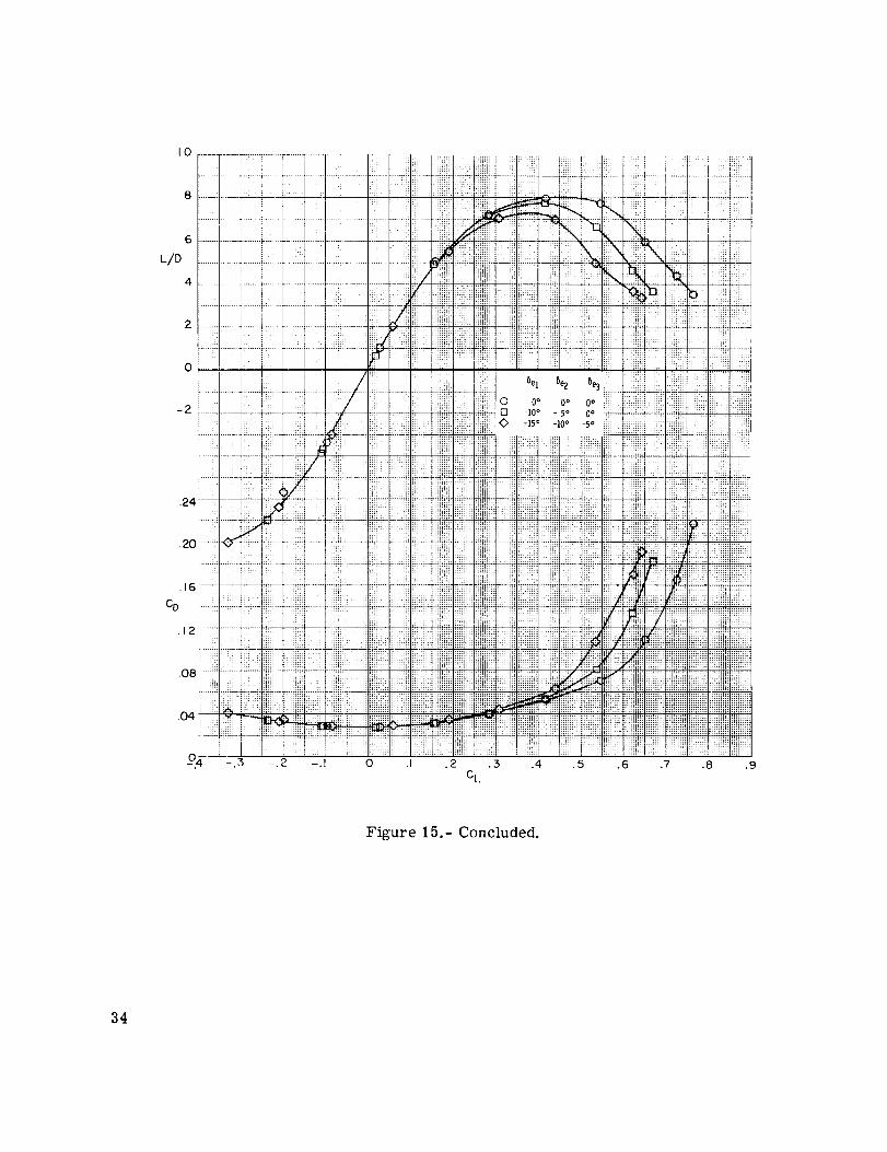
I0
L/D
-2
.16
CD
.12
,O4
04 -.3 -.2 -.I 0 .I
Figure 15.- Concluded.
34
Cm
...........:i _% =.._:+.-- :f_-_..:-+it-;---:;!
i_ i_: ..........ii :. ..................
:-ii _ /. iiil iiliii
iii dii: i: : : :......; i ......k,:,i .............. .........iii!;: k" '! _ _::_!i!! i;i!: ] i!!:::: Ji:: i i]; ;;1 '
IE!I_;!:::;I::iiiii;Ei!iEi]]i]!_:i!iEi!il":::::;;i;iiFJiii;iiJ;iii;;i;;iiiii;;iii:,il/fili:_;;;;;;;_;;i;_;;;!i_;_
]!!:]Ui!ii_!_]]]]]]1]ITTii!_E]_]_]_!!i]
- _o oo ilJlii!i:_,_:iiii_.!_:ii:_iBi::!!!!_:::. .......if/.:_ijL_1o° _5o u!rm_t_l:ii_:::itiF:i]:::::.]_.!::]i!i_!:dl_iTu_
............ it!ii.!ii! ............:.....!_i__Ill!flail] i]:.i::iii_ul_ :i_,m:_[i::ii ]i iiiiiiiii;:dii;,';.......,; ,;;_ _::::1 :: i;_ill _Hiiil;!!I_IE;!:::::=;: iili!!
:,ii]li]] I_I!EEil_:.,,:::i:.iUil ]_fi];_ ;;;;!_
'--;_ ]]ii]ili!i!;:;ii::::m::i!]i...............ii........
iI:_ :::/:i?_ii',................[t!_,!_'_.]%_ii!It_iiii':iI:,i]i]iil!_:;:__i!:;:iii:..........., -: _ ......... m::m: :._m: _u.-,
_!? ii!l!li!::::;]11':]!i2:::_im.........;iiii':!ii*.iill!i.......!!t'<lilg_!!!!i_u uI_ :diii!ll_ i_iUiii:........
iilt ! ":" ' ......;:: ', ht_?_ I t!!" !! ]_* ++ _ !]t
E!_]] JIM:.. .... _ b ]: fl!HH ....
k:: !!fittt '_ l!_i_}_!] !!!ttt', !TT!!tt!! !:11!!12 ]!'!!_ 11111?:"
.....!i rll t;:tl Iii}iiiii i_t?t?!?!!t_;.' i_t,
ii]]ii....................iii_iiiiiJ!i_ii'_lili !r_,,,_,,,i]iii!i_::.,,_,::.,.,.!ijfii!!_]_
.5, .6 .7 .8 .9
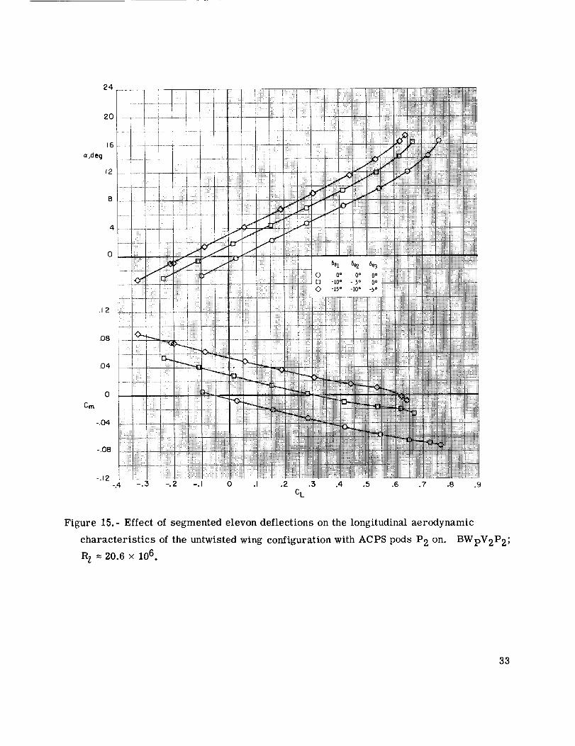
Figure 16.- Effect of segmented elevon deflections on the longitudinal aerodynamic
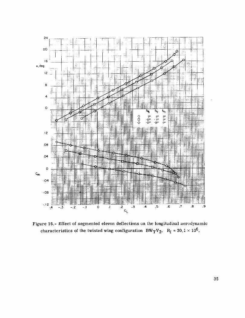
characteristics of the twisted wing configuration BWTV2o R l = 20.1 × 10⁶.
35
2O
.16
Co
.12
0-.5 -.2 -.I 0 .I ,2 .5 .4 .5 .6 .7 .8 .9
CL
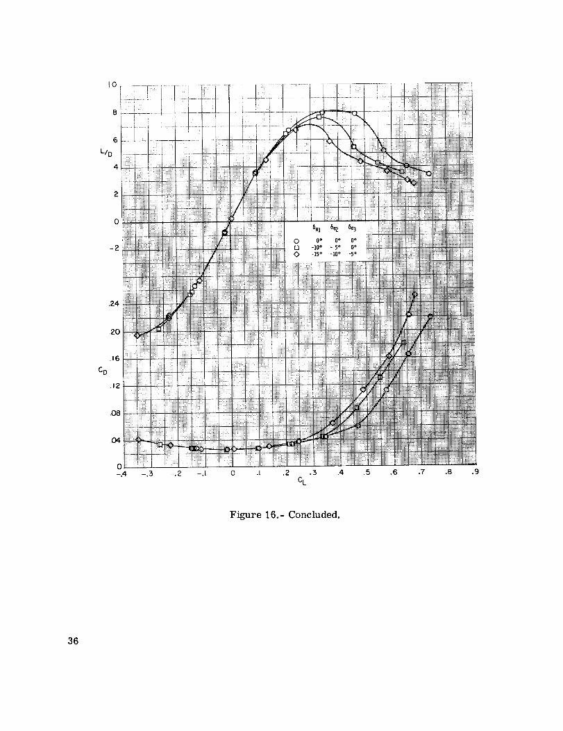
Figure 16.- Concluded.
36
CL
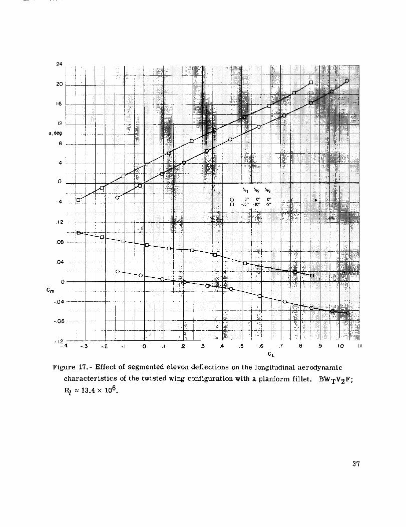
Figure 17.- Effect of segmented elevon deflections on the longitudinal aerodynamic
characteristics of the twisted wing configuration with a planform fillet. BWTV2F;
R 1 = 13.4X 10 6 .
37

I0
6 _.__..................
L/D :,...... r........ _ .................
i
ii i
2 ' :T ==-...... : ....., : .............
i
ol i :i
-= 1 i fI ..... ; :.............. +. .................... ::r
...........t:: .....7.24 ......... -t---
.20 .........
i
C D ........;:::._..........................i i
I iii i:L_J 11_ L_L i ....
::/:los
: r iiii
__!! '-: _T r- :!!:77 -Zil;: :,:::
0 iii:i ,_ :
-,4 -.:3 -.2
-----r
:_i ill
:7-7
iiil---;i{i{
__ii!i!
"'11!!_
!i!_;
iii!!i
i!i_!?::!!i
!!:i;ii;i.:i:!ii!i:_ii i!ii !
I :
: ..... _ "_ ! ;
................ . :, _ :
: ::: . :::::..... ......... " iiii
: ::: :: :::: :
:: 0 0° 0o 0o :: :::::_ :
i: i : :!i! /: i[[!:, i
......... : .... ::.::;:: : - :::
i:.i __;,.2_.__.___ w! ill! e! !!i!::i ....::i::i;: i ( _ !i:i:: ::: :;! ii_i{i{_>:: _i!ii :_iiii{i
71!i i! = .........................-, : x:: .... : - ::.::aa.... ! :;: : !!_E: i{{]!1!!
i iili ::: i ;{:: i: ;/' L g:4i{ i_:::. +!iiiii_ ii{{i{{{
]]!: :i ! h : iii i .... Z ]E!i]!!
_i£{iiiii_i tlhilil i._i!i !ilh iiiiiil; " Z !!i{{{{<_<;il ilii ;:::_:,:i!i ;; hhW: :i i: :::: Z I;::: E : _i :lw:::" :;;Im; iEi!ili
.... _:: ;.............. :=:< {}{iiglgiili;iiie i{{!11]li_:!iii:il _::[ii!iil !ih{i ......... _i_i!!i__!i_i{i_ i!iiiii! :i ', _....... . ........................ hi!!111
i{{{iii:................. iiiiiiii:/ii <_:_:ii{{ii{{li!!!iiillii!ili!!i_iii_t*1 ..............:iiii!i]; :=,.a_hii!_!!q{ii_igii
;::: ;::; : :;;;. ........ :w: :_ i:::x![ F ,_ili_i !_}!i_!
[ : ii :i _ i _:._:j_/j!_Lii_ili::_::!!:]:i
,5 .4 ,5 ,6 ,7 .8 .9CL
Figure 17.- Concluded.
:i(i : ::_i!i ':!:i_i!:i::: ::::: :::,::::::
i:!: :ii[ ;:iil]]]
!: i: : ]]:i!
i iii'!Iiiiii!i:i::i::: _ i, ii_iii?!il:i': i_!_i:_I:: !iil;ilh
.......... illiii_il11:1:1 [121... ,i!11!;;
_2 [_iiiiiiiiilH!i
£Jill ,1:[ 221.1gi[glg[;:
<2iil !Ii iiii!i!i!
,,.¢ :;:;::l:iSi:!i!
ii_!i;!iii_:iiii!!!!ot:: ::
iili:_
iiiiii[!ili_!%iiiiii!!ir!;)iii l!!?i_iii!!!i?ili'........iiiiiiiiiiiiiil!i
:_ii!ii_iiiiili!qiiiii!!i
iii?'i ii: :"!!i[i!iii!
i!;i!ili_..............;!i!: i i!!_?i
i!!!ih'l_f!!it_!
iiii{ili li;;iF't!!!_{{i_
!!i!iii!!_;i_ilili!iii!iii!ii!i }iiiiii!iilH!!iiiiiiti ii;iiiiiliiiii_!i
:!!!! !iilhlE !!!!; i
:!iiiiii i!!it gli_iiiti
.....iii!iiiiiiiiii _i:_i_ i!iiii!i!ii!!!ill
1,0 I,I
38

C m
iliii!_i,:ilii!!:ii_ iii! _
......,!! !+ :--_
_;il _ ilii
_i _l
Tit'
2i;2.; ....} ;
...... a
x :: x: ;:
ili[ [_i ii
iii[iiiiii i iiii iiiiili: _!
figgf!!irii_'li
.4
Figure 18.- Hypersonic aerodynamic characteristics for
configuration BWpV 1. M = 10.33.
39

--0 Experimental
Analytical
L2-
.8
eL, trim.4
C
.0_
.0_
Cm
-.0_
-. 08
4
o-
o..
o e-
c_ d_
/ A na I),tica I Experimental
CL, trim at a : 17° 0.77 0.66
Vmin, des 150 knots 162 knots
em/CL (Design P/U -0.080 _ -0.078 _
"} 6eI= 6e2 = 6e3 = -100
Z_ff}6el 6e2 5e 3 0°
Figure 19.- Comparison of subsonic analytical aerodynamic characteristics
with wind-tunnel experimental values for configuration BWpV 2.
Fillet
o_ Offo .... On
.12 1.0
I . 8:.08 _._.._ _ •
•04[__-,_. eL,trim 6
-.04_. _ _ _ _e3 :-5 2
"t_ ,.,o_08[ , 0• 0 4 8 12 16 20 24
deg
//
/
i I I4 8 12 _6 _od_
Figure 20.- Effect of the planform fillet on the subsonic aerodynamic
characteristics of configuration BWTV 2.
4O
Wing Elevons
Plane Unsegmented--- Plane' Segmented--- Twisted Segmented
.8
_'__\ .6
/ \
/ _ CL,,, trim/ \ .4
// /
//
4 I_ l_' 16 O, 4 8 ]2 16 20
a, d_ a, deg
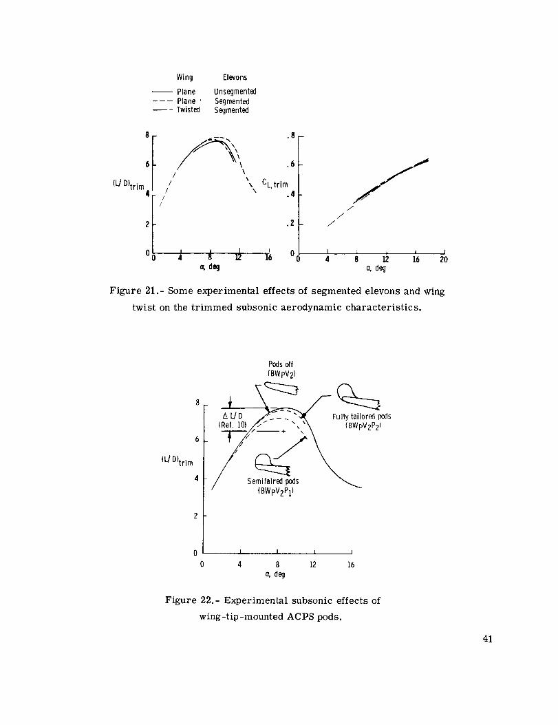
Figure 21.- Some experimental effects of segmented elevons and wing
twist on the trimmed subsonic aerodynamic characteristics.
(L/D}trim
Podsoff
(BWpV2)
(BWpV2P1)
0 I I I i
0 4 8 12 16
deg
Figure 22.- Experimental subsonic effects of
wing-tip-mounted ACPS pods.
41

•O8
•04
Cm
-. 04
-. 08
-. 12
-. 16
f _ Analytical ! 5el : 5e2: : -45°
5e3Experimental
'25
45°-\ \_0
_ --
_ 20°_ _ ....
/ /
8el : 5e : be3= 0o _ Analytical-/f 40°2 L Experimental
48 °
-.20 I t I _ I I I I0 .2 .4 .6 .8 1.0 1.2 1.4 L6
CN
Figure 23.- Experimental hypersonic trim characteristics as compared
to analytically obtained values for configuration BWpV 1.
Effects of segmented elevons and wing twist.- The effect of varying spanwise deflec-
tions of trisegmented elevons (more negative for the inboard segments) and wing twist on
the longitudinal trim characteristics of the configuration is shown in figure 21. Use of
variations in spanwise elevon deflections produced little or no increase in trimmed lift
coefficients at landing angles of attack (or > 15 °) for the basic plane wing configuration.
However, some increase in trimmed (L/D)ma x was noted for the configuration using
variations in spanwise elevon deflection for trim. Only slight changes in trimmed lift
coefficients were produced by incorporating linear wing twist (4.5 ° washout) in the sub-
sonic model although some reductions in L/D are attributed to the introduction of wing
twist for angles of attack near and above (L/D)max.
Subsonic ACPS tip pod effects.- Significant degradations in trimmed lift-drag ratios
have been associated with the addition of unfaired wing-tip-mounted ACPS pods to space
shuttle orbiters (ref. 10). Figure 22 shows the (L/D)max decrement from reference 10
42
to be about 1.2 which would result in an approach glide-slope angle increase somewhat
greater than 1 °. An attempt was made to assess the effects of tailoring the ACPS pod
external shape on L/D ratios. For this purpose, two wing-tip pod configurations were
tested on the plane-wing configuration BWpV 2 (fig. 5(b)) which fulfilled the volumetric
requirements for roll-control ACPS. The two configurations represented semifaired and
fully tailored designs. Addition of the semifaired pod to configuration BWpV 2 produced
a trimmed (L/D)ma x decrement of about 0.7 (fig. 22) whereas the fully tailored fairing of
the pods resulted in a decrement of only about 0.1.
Hypersonic analytical and experimental comparisons.- The basic longitudinal aero-
dynamic characteristics obtained for configuration BWpV 1 at M = 10.33 in the Langley
continuous-flow hypersonic tunnel are shown in figure 18. A comparison of these data
with the analytically predicted pitch trim characteristics is presented in figure 23. This
experimental data comparison indicates a reduction of approximately 5° in maximum
trimmed angle-of-attack capability for the configuration with 5el = 5e2 = 5e3 = -45o; this
reduction thereby produces an amax, trim of about 40 ° for the design payload condition
(Xcg// = 0.650). Experimental effects of fuselage widening and of changing the fuselage
nose camber (see ref. 9) indicate the necessity of only minor modifications to increase
the trimmed hypersonic maximum angle of attack for the present configuration from 40 °
to 50 °. Although no hypersonic data were obtained for configuration BWpV1F (incorpo-
rating the planform fillet and the aftward wing movement), estimates of stability and
control indicate the possibility of some improvement in hypersonic maximum angle-of-
attack trim capability for this configuration.
Summarization of vehicle performance characteristics.- During the course of the
present analytical and experimental orbiter wing design study, a configuration BWTV2 F
(incorporating a 0.035 aft wing movement) was developed which would essentially satisfy
the established design guidelines. Figure 24 summarizes the experimental aerodynamic
performance, stability, and control characteristics for this configuration. Stable subsonic
static margins were found for the configuration throughout the envelope which are in accord
with the preset study guidelines as is the Vmin, des value of 148 knots.
Maximum hypersonic trim capability for configuration BWpV1F is estimated at
amax, trim _ 400 for the design payload condition. This value is approximately 10 ° less
than the guideline value of 50 ° which might be attained with some fuselage nose reshaping
and/or elevon resizing which would not adversely alter the subsonic flight characteristics.
43

80 x 103
6O
Payload,
Ib
4O
2O
/Vmin des • 148knots_ /
%'L"-o.o8o iX/
Estimatedar_ax_
Payloadenvelope
0
Forwardpayloadstation
J t I
.1 .2 .3I
.4 .5
Payloadcenter of gravity//.
40 000
35 000
30 000
25 000
20000
15 000
10000
5000
0
Figure 24.- Summary of experimental performance characteristics
for configuration BWTV2F as applied to the various landed payload
loadings of the space shuttle.
Payload,
kg
SUMMARY OF RESULTS
An analytical and experimental investigation has been made to define a space shuttle
orbiter wing configuration meeting requirements for landing performance, stability, and
hypersonic trim for a specified center-of-gravity envelope. The analytical part of the
study was facilitated by the use of the Optimal Design Integration system (ODIN). Limited
experimental studies were made in the Langley low-turbulence pressure tunnel and the
Langley continuous-flow hypersonic tunnel to verify the aerodynamic characteristics of the
orbiter configuration selected analytically. Results are summarized as follows:
1. Use of the ODIN system greatly simplified the handling of analytical data while
maintaining compliance with the space shuttle general vehicle requirements and allowed
the expedient selection of a desirable wing planform. The analytical aerodynamic esti-
mates obtained by using the ODIN system were in reasonable agreement with experimental
results obtained subsequently for the orbiter configuration selected.
2. The analytical study suggested reductions in wing sweep to produce a minimum
wing area (minimum weight) configuration. Reductions in wing area and sweep also
44
enhanced the high-angle-of-attack trim capability at hypersonic speeds. This trend,
however, was constrained by entry heating considerations to preclude wing leading-edge
sweep angles below 45 ° . Attempting to meet the hypersonic and subsonic guidelines
directed the study toward using a negatively swept wing training edge to provide increased
hypersonic trim capability and desirable subsonic flight characteristics.
3. The analytically selected orbiter configuration required minor experimental
wind-tunnel refinements to provide a viable orbiter configuration. The primary refine-
ment was the addition of a small planform fillet to increase Lift coefficients at landing
attitudes accompanied by an aft wing movement.
4. Significant reductions in lift-drag ratio losses due to the addition of attitude-
control propulsion system wing-tip pods were attained by tailoring the external shape of
pods designed to house the roll-attitude control system.
5. The use of sequentially deflected segmented elevons improved subsonic trimmed
lift-drag ratios which may be beneficial to landing-approach glide-slope performance.
Langley Research Center,
National Aeronautics and Space Administration,
Hampton, Va., January 18, 1974.
45
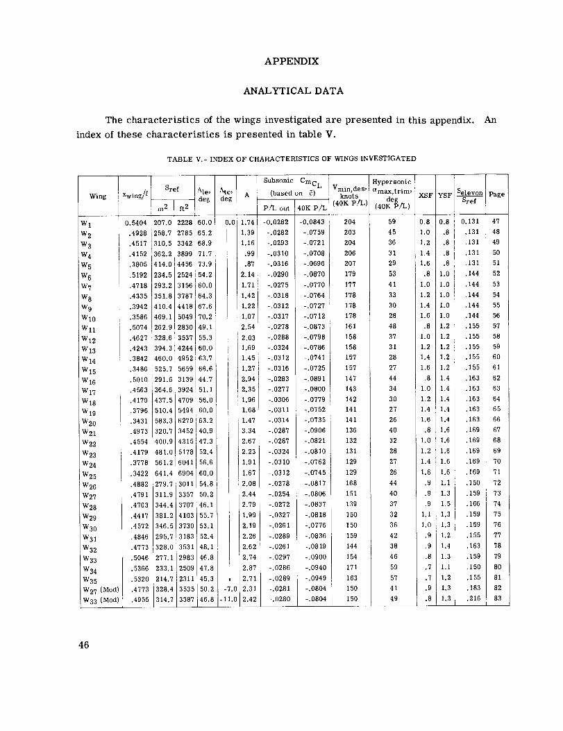
APPENDIX
ANALYTICAL DATA
The characteristics of the wings investigated are presented in this appendix.index of these characteristics is presentedin table V.
TABLE V.- INDEX OF CHARACTERISTICS OF WINGS INVESTIGATED
Ale, Ate,Wing Xwing// A
/
deg deg
W 1 0.5404
W 2 .4928
W 3 .4517
W 4 .4152
W 5 .3805
W 6 .5192
W 7 .4718
W 8 .4335
W 9 .3942
W10 i .3586
Wll .5074
W12 .4627
W13 .4243
W14 i .3842
W15 .3486
W16 .5010
W17 .4563]
W18 .4179
W19 .3796
W20 .3431
W21 .4973
W22 .4554
W23 .4179
W24 .3778
W25 .3422
W26 .4882
W27 .4791
iW28 .4783
W29 .4417
W30 .4572
W31 .4846
W32 .4773
W33 .5046
W34 .5366
W35 .5320
W27 (Mod) .4773
W33 (Mod) .4955
Sref
m 2 ft 2
207.0 2228
258.7 2785
310.5 3342
362.2 3899
414.0 4456
234.5 2524
293.2 3156
351.8 3787
410.4 4418
469.1 5049
262.9 2830
328.6 3537
394.3 4244
460.0 4952
525.7 5659
291.6 3139
:364.6 3924
437.5 4709
510.4 5494
583.316279
320.7 3452
400.9 4315
481.0 5178
561.2 6041
641.4 6904
279.7 3011
311.9 3357
344.4 3707
381.2 4103
346.5 3730
295.7 3183
328.0 3531
277.1 2983
233.1 2509
214.7 2311
328.4 3535
314.7 3387
60.0
65.2
68.9
71.7
73.9
54.2
60.0
64.3
67.6
70.2
0.0
49.1
55.3
60.0
63.7
66.6,
44.7
51.1
56.0
60.0
63.2 i
40.9
47.3
52.4 I
56.6
60.0
54.8
50.2
46.1
55.7
53.1
52.4
48.1 1
46.8
47.8
45.3i ,
50.2 -7.0
46.8 1-11.0
1.74
1.39
1.16
.99
.87
2.14
1.71
1.42
1.22
1.07
2.54
2.03
1.69
1.45
1.27 i
2.94
2.35
1.96
1.68
1.47
3.34
2.67
2.23
1.91
1.67
2.08
2.44
2.79
1.99
2.19
2.26
2.62
2.74
2.87
2.71
2.31
2.42
Subsonic Cmc L
(based on 5)
P/L out 40K P/L
-0.0282 -0.0843
-.0282 -.0759
-.0293 -.0721
-.0310 -.0708
-.0316 -.0696
-.0290 -.0870
-.0275 -.0770
-.0318 -.0764
-.0312 -.0727
-.0317 -.0712
-.0278 -.0873
-.0288 -.0798
-.0324 -.0786
-.0312 -.0741
-.0316 -.0725
-.0283 i -.0891
-.0277 -.0800
-.0306 -.0779
-.0311 -.0752
-.0314 -.0735
-.0287 -.0906
-.0287 -.0821
-.0324 -.0810
-.0310 -.0762
-.0312 -.0745
-.0278 -.0817
-.0254 -.0806
-.0272 -.0837
-.0327 -.0818
-.0261 -.0776
-.0289 -.0836
-.0261 -.0819
-.0297 -.0900
-.0286 -.0940
-.0289 -.0949
-.0281 -.0804
-.0280 -.0804
Hypersonic
Vmin, des' amax,trim,
knots deg40K P/L) (40K P/L)
204 59
203 45
204 36
206 31
207 29
179 53
177 41
178 33
178 30
178 28
161 48
158 37
158 31
157 28
157 27
147 44
143 34
142 30
141 27
141 26
136 40
132 32
131 28
129 27
129 26
168 44
151 40
139 37
150 32
150 36
159 42
144 38
154 46
171 59
163 57
150 41
150 49
XSF YSF --
0.8 0.8
1.0 .8
1.2 .8
1.4 .8
1.6 .8 '
.8 1.0
1.0 1.0
1.2 1.0
1.4 1.0
1.6 1.0
.8 1.2
1.0 1.2
1.2 1.2
1.4 1.2
1.6 1.2
.8 1.4
1.0 1.4
1.2 [1.4
1.4 1.4
1.6 1.4
.8 1.6
1.0 1.6
1.2 1.6
1.4 1.6
1.6 1.6
.9 1.1
] .9 1.3
.9 1.5I
1.1 1.3i
1.0 1.3 i
.9 1.2
.9 1.4
.8 1.3
.7 I.i
.7 1.2
.9 1.3
.8 1.3 t
Selevon
Sref
0.131
.131
.131
.131
.131
.144
.144
.144
.144
.144
.155
.155
.155
.155
.155
.163
.163
.163
.163
.163
.169
.169
.169
.169
.169
.150
.159
.166
.159
.159
.155
.163
.159
.150
.155
.183
.216
An
Page
47
48
49
50
51
52
53
54
55
56
57
58
59
60
61
62
63
64
65
66
67
68
69
7O
71
72
73
74
75
76
77
78
79
8O
81
82
83
46

APPENDIX- Continued
ODIN Wing W 1
3o
4.
7.
UVERALL CCNF tbUB/_I ICN_KEA, PLANFCRM (SFT)
LENGTH, hUSE [0 _IN6 LE
LENGTH, r_USL TO WIN(, C/4
A_GLE, GRCUhU PLANE
AT BCOY
*F[XEC*
2ggg.4
710.02 IN
903.27 IN17.00 DEG
FUSELA;E
Ar_EA, _ETTEC
LcN,_ TH, NoSE IU _;_O U_: BGOY
6307.0
1215.0
SFT
IN
,,1 NG
AF,,EA, TI EU_ETICAL OF, TOTALAREA, ELEVUN
SPAN
CHO_,C, ,lEAN ArhCDYNAMICCHOW, D, UENTERLINE RC,3TCHU_ U, [IP
[APER MAIIO, IPEU_ET[CALASPECT R_TI_, ThEuRETICAL
ASPECT _,ATIC, [XPUS_O SPANA:_G__E, LEADING Eoo_- S_ELP
A_SLr, [_AIL_NG LDGI: SWEEPANGLE, DIHECV _L
_LiLk, INCIUENCE
AIRFCIL SLCTICN, ROUTAI_,FCIL .<ECIICN, TiP
*FIXEC**FIXFC*
*FIXEC**FIXFC*
*FIXEr*
2228. 1
291.53
746.40
510.R8
753.05
100.66
.141(:3
1.7364
1.5882
59.sg8
0.0
7.0
i.5
008-64
008-64
SFTSFT
IN
ININ
IN
OEGDEG
DEGBEG
O,t0A :4A_,S P_c, PE_TIES
rL lu, bT CENDITICNJ_L_I Tk:k LNDG (_,/,tciK PL)LIF,i5t IEF, LI'_DG (W/J PLI
_ING ,_E lGh[
IPS ,LIGI-I
wEIGH1 ILLS)191590.2
1D1590.2
tzqg_l.5229q0.7
X-CG |FTI
70.881
73.2o_
X-CG (PC
6Q.6E4
66._3
LI
PK INCiPAL PhRAMLI ERS
x-SC _LE FAC ICHY-bC _ut: FACTOR
L)[STA,_Cc TU LEAulNG EdGE UF FXPOSEO WI,qG
SCtX= .8Ct'IO0SCL'_= .BOO00
XOF=710.023 IN
LA NO 1 .,iO Pc_PE_MANCE
,4[I_It_UM LANCING SPEED (_I_OK PL)
STAT [C _ARbIN (SUBSONIC) (wI40K PLI
STAT IC MARGIN (SJBSUNICI (w/L) PL)
T_IM L|F[ CCE_- FUr, LANDING (ALPHA=f7 t)E(; )
203.5 KT
-.0863
-.0282
.6134
MYPE_uh_IC AERO[.¥NAMIC T_IM CAIA
I_IM ANGLE EF ATTACK AT _LEVCN:-45 ObG 5B.5q DEC;
47

APPENDIX- Continued
ODIN Wing W 2
I. uVERALL CCNFIGUR,aTIC_AP, EA, PLANFCRM (SFT)LENbTH, hOSE TO _IING LE AT B(}f)Y
LENGD'I. I_CSE TC _ILNG C/4
ANGLE. GkOUND PLANE
2. FUSELAGE
A_,EA, tNEITEO
L ENb TH, I_OS E TO I:NL_ OF bUL)Y
=_. WINGAP,EA, TFEUP, ETILAL On TGIAL
A_ch, ELEVGN
SPANCHUb, C, MeAN AE_,UL)YNAMIC
CrlU,:',C, CLNIERLINE RUOT
CHOW, 13, T AP
TAPER RAIIO, II'EdEETICAL
ASPECT _,AllC, I_EUKETIC,aL
ASPECT E_I"IU, EXPOSED SPAN
Awi_uLE, LEADING E_E S_EEP
AN_LE, TRAILING EDGE SaEEP
A,',_GLEt OIHECRAL
AI,IGLE, INCI LENCE
AIRFLIL _ECIION, _,OOT
AIF,FCIL SECIIEN, TIP
I*. U40A ,_ASS P&CPEBTIES
FLIGHT C(,NO IT IUN
OF,d,I TEk Li,,iDb {W/_.OK PL)
Ur_b_ IER LNdG {_,/L} PLt,,IINL, ,,E IGrtT
IPS WE:151-T
WEIGHT (LB)
L94150o0
L54150.(I
12994.4
25J49.5
5. P_INCIPAL P,a_AMETERS
_-SChL E FAL,TO_,
Y-SCALE FACTCIR
_ISTANCc TU LEADING EJuE CF EXFt3S[D WIN(;
o. LANOI_G PEi_i:LF,MA_CE
,4INII"UM LAI_LING ::.PEED (W/40K PLI
3rAT ic '-_AkGJN {SJI3S(Ji',_[C) (WI4OK PL)
_TAT IC MARGIN (SUbSL;,_ICI IWlO PL}
r_,IM LI_T CLEF FJ_ LA:wLII;_G (ALPHA=17 {)EGI
7, HYPEr'SU_IC AEKO_YI_AMLC T_IM CATA
Fkl_'i ANGLE LF AT[_C_. AT ELEVEN=-45 DEC,
*FIXED*
3321.0
648.44 IN
890.00 IN
17.00 DEG
6307.0 SFT
1_15.0 IN
*FIXF[*=FIXES*
_FIXED__FIXFE*
_FIXFE*
2785.1 SFT
364.42 SFT
746.40 IN
_38.60 IK
941.31 IN
133.32 IN
.14163
1.3891
1.270565.207 _EG
0.0 DEG
7.0 OEG
1.5 BEG
008-64
_08-64
X-CG (FIT
71.024_4.1_5
X-CG (PC L)65.3e2
67.681
SCLX= 1.0000
SCtY= .80000
XOF=648.442 IN
203.3 KT
-.0759
-.0282
.4980
45.35 DEG
48

APPENDIX- Continued
ODIN Wing W 3
[. UVE_ALL CUNFIGU_,ATI[.N
_Ki.-A, PLANFCK_ ISFT|
LE,_GTH. I_,uSE TO ,',lING LE AT BflDY
L_-NGIH, NCiSE TU _ING C/4
ANLiLE, GRCUIXU PLANE
>'. FU SE__AbE
AREA, WEITEC
Lt:NGTH. NOSE TO END ()F BODY
3. WING
A,_EA, TI-EiJF,EIICAL dR TOTAL
A_,E/A , ELPVUK
_,P ANCrlU_ U, ;4_AN AEF,I]L)YNAMIC
Crld_C, CENTEMLII_E RUuTCr,u_,O, f IP
TAPL_ R_IIU, TFEOKETICAL
ASPEbl K_TI&, THr-ORETICAL
ASPECT _,_1lL, EXPuSED SPAN
A,,,GLE, LEAUING LObE SI_EEP
ANbLE, T_A/LING EOGE SWEEP_r_..JLE, L; |HE LRAL
AN(,L E, /_,CI LENCE
AIRFOIL SECTILN, kUUT
_I_FEIL SECTION, I'|P
_.. 04dA 4ASS PRCPEMTIES
FLI_hI CCNL) IT IONOi_LII Tt:_ LNDG IWI@UF, PLI
U<BI TeR [NL)G (_,/d PL}
_INb ,,E ICr_T
WE IGHI ILltl19(; i2q. O
150729.0
135O8.6
Z/I14.4
X-CG IFT)_2.55l
75.286
5. PKI:_uIPAL PARAMEIERS
X-SCALE FAC I_F_
Y-SC _LE FACTOR
_,ISEANCE TU LEAUl;_C, EiJGE UF FXPGSEO wING
o. LAi,,OINb P_:I-_FI:F(,MANCE
M|NIMUM LANCING ,.iPEEU (WI40K Pt I
STATIC MARGIN (S,JbSCNIC) (w/40K PLI
:)TATIC MAI.,,GIN ISO_SBNIC) (w/[J PL)
Tl,,I_,iLIFT CLLF FU_ LANI)I_,_G (._LPFA=I7 DEG)
l. rl'rPl::,.-,S[,NICAEF,OCYNAMIC T_IM bATA
TRIM ANGLE EF ATTACK AT ELEVnN=-45 OEG
*FIXED_
3(42._5_4.36 IN
88_o23 IN
17.00 BEG
E307.0 SFT
1315.0 lk
*FIXFC*
*FIXEE**FIXEC*
*FIXFC**FIXED*
3342. I SFT
437.30 SFT
740.40 IN
7_E.32 IN
I129.E IN
159.98 IN
.141631.157_
[.058868.947 OEG
O.O OEG
7.0 DEG1.5 DEG
008--64
0C8-64
X-CG IPC II
66.208
b8.70_
SCLX= 1.2000
SCLY: .80000
XCF=594.360 IN
204.1KT
-.012|
-.02_3.417P
36.33 DF G
49
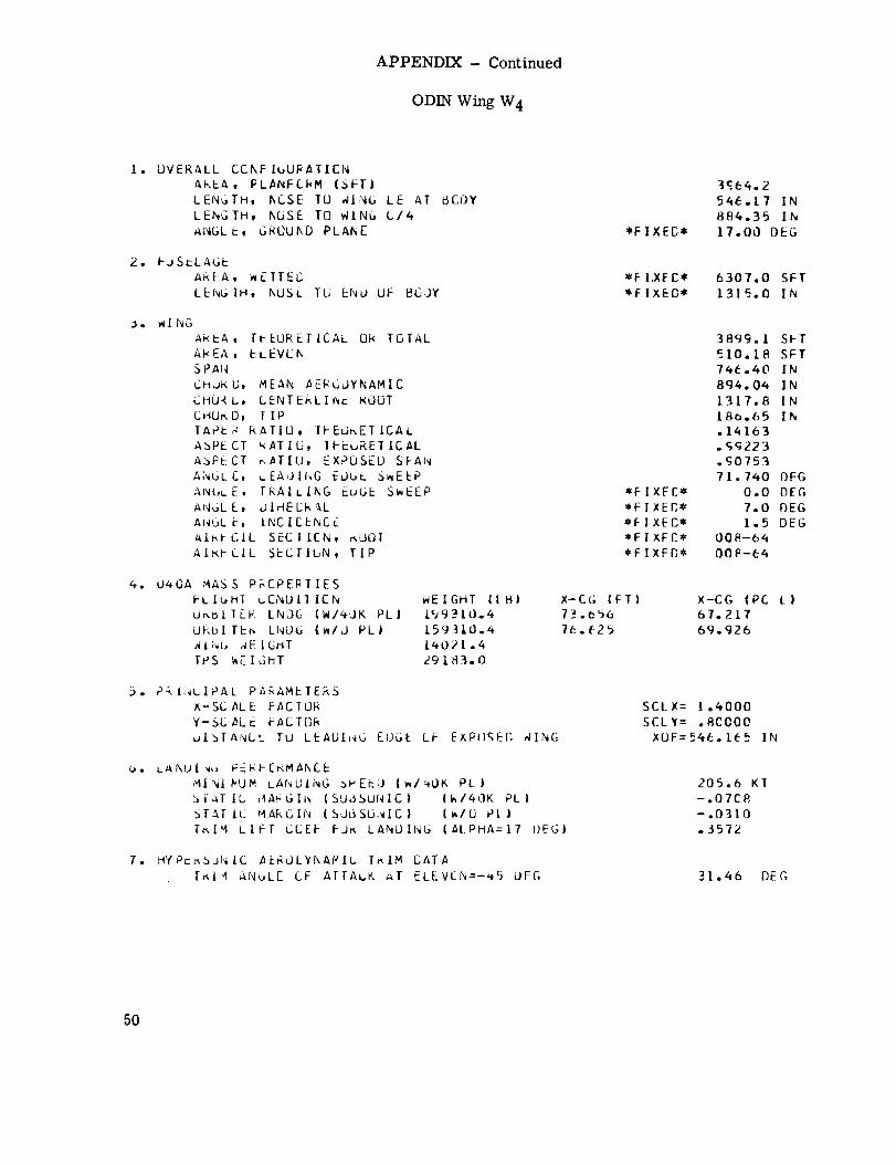
APPENDIX- Continued
ODINWingW4
I. OVERALL CCNFIL;URAIICNAREA, PLANF{kM (S_TILENGTH, hCSE TU _ING LE AT _CI)Y
LENGTH, hOSE TO WiNG C/4
_NGLE, C,I4(]UhD PLANE
2. I JSELAGE
AREA, _wE TTEC
LENGTH, NUSL Tb END OF _G]Y
J. WING
AREA, Ti EURETICAL Ok TGIAL
AI_EA, ELEVCN
SPAN
CHJ_L), MEAN AEI_GJYNAMIC
CtiORL, CENTERLIJ_ _UOT
C tIUr,D, TIP
IAP_ RATIO, II-EUnETICAL
ASPECT RATIO, IFi-UREIICAL
A3PE CI RATIO, EXPOSED SFAN
ANGLC, ,_EAOING EObL S,,EEP
AN(,LE, TRAILING EDGE S_EEP
ANUL E, UlriEL;k'_.LAhlUL [-i, I.NCt[,ENC_AI_.FGIL SECTICN, r_oOI
AI,kFCIL SECIIbN, TIP
4. 04OA MASS PF.CPEPlIES
FLIbHI bCNDII ICN
Ur,bllLF LNDC: {WI_eJK PLI
dEbl TEn LNL)L; IWILJ PLI
AIN{, _EIGltITPS _E I G_T
_EIGHT II _I
159310o4
159310.4
l_021.4
2918_.0
_. P kI,_LIPAL P_AMETERS
X-SC _L E FACTOR
Y-SC ,_LE HACT[]F_
DISTANCE TU LEADIHG EL)G_ LF EXPl)gEg alNG
o. ua, l_U[ w,_ Fr. F4PCKMAI_C.EMINI YUM LAhL)ING _,PEi-=L) (m/_O_ PL)
:::.I-AT tb _4A_GIh (SUL_SUNIC) (W/40K PLIbfAr It. MARGIN (SObSU4IC} (_/[J PlITr.lM LIFT CCEF Fd_ LANDING (_LPHA=17 I)EGI
7. H fP_r,,bJNIC ,AERULY_AWI(. T,,IM CATA
Tr_IM AN_LE CF AITAbK _T ELEVEN=-'_5 UEG
*F IXEI]*
3qe4.2
54£.17 IN
884.35 IN
17.00 DEG
6307.0 SFT1315.0 IN
*F I XFC_,_F I XEC,_
*F 1 XEB**Fl XFl:*
*FIXED*
3899. I SFT
510.18 SFT
74E.40 IN
894.04 IN
1317.8 IN
180.65 IN
.14163
. £q223
.S0753
7 I. 740 BEG
0.0 DEG
7.0 r)EG
1.5 DEG00fl-64
OOfi-_4
X-C(; IFT)
7_ .e56
7(::._25
X-CG IPC L)
67.217
69.926
SCLX= 1.4000
SCLY: .F_CO00
XOF=546. i# 5 IN
205.6 KT
-.07C8-.0310.J572
31.46 DEC;
50
APPENDIX- Continued
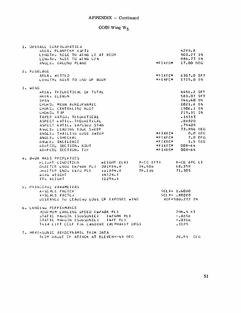
ODIN Wing W 5
I, OVERALL CCI_F |60_AIIC,_
_REA, PLANFERM |SFTJ
LENGTH, hOSE T(J WING LE AT BCOY
LENL, TH, hoSE TO _ING C/4
ANGL b, GRCUND PLANE
2. FUSELAGE
AREA, WETTED
Li-Nc,TH, hU3E [0 _ND OF BOOY
3. WINGAREA, IFE_RETICAL Off TOTAL
AREA, ELEVGNSP&N
CHEJKD, MEAN Ac_GOYNAMIC
CMORC, CENTEkLIhE ROOT
L.HOkD, TIP
TAPER _(ATIO, IEEO_ETICAL
ASPECT kATIO,.TPEUKETICAL
ASPECT R_TIC, bXPGSrL) SFAN
ANGLE, LEAOING E_uE Sv,EEP
ANGLE, THAILING EUGE SWEEP
ANGLE, CIHEE_ALANoLE, IhCICENCE
AI_FCIL SECIION, ROUT
AI_FCIL SECTI{JN, TIP
_. O',OA MASS PRCPF_.I_IIESI-LIL,hT CENOITICN
L3r',L_ITER LNUC IH/_UY', PL}
JK_TER IND_ (k/J PL)
_l_qG ,WEIGHTlPb _£1Ghf
,EIGHT (LH)201_84._
L01884.814_24._
31254. I
5. PRINCIPAL PAI,AMEIERS
X-SCALE FAG ICR
I-SCALE FACTCLR
OlS[ANCE TO LEAOI,qG _L)GE CF EXPDSEC _ING
6. LANDIiwG PEPFCkMANCE
AINI MUM LANL|NG SPEED (WI40K PLI
_TATIC WA_GIN ISUoSUNIC) IWIk()K pEISTATIC MAKblN (SUBSONIC) (WIC PL)
T_I_4 LIET CCEF F,}_ LANDING (AL_HA=17 DFG)
7. HYP_KSUNIC AEROCYf_AMIL TP,|M DATA
rF.IM ANL, LE [F A T(ACK AT ELEVEN:-45 DEG
*FIXED*
4285.8
5C0.27 IN
886.77 IN
17.00 OEG
6307.0 SFT
1315.0 IN
*FIXEE**FIXEE**FIXEC*
*FIXEC*_FIXEG*
4456.2 SFT
583.07 SFT
746.40 IN
1021.8 IN
1506. I IN
213.31 IN
.14163
.86820
.7q40973.A96 DEC,
0.0 BEG
7.0 bEG
1.5 bEG
008-64
008--64
X-CG (FTI
iq._Oo
78.1J6
X-CG (PC LI68.358
71.305
SCLX= 1.6000
SCLY: .80000
XUF=500.272 IN
206.9 gT
- .06c6
-.0316
.3125
28.85 BE(;
51

APPENDIX- Continued
ODIN Wing W 6
I. OVERALL CCNF IGURATIuN
AREA, PLAnFE_M {St_T}LENGTH, hOSE TO _ING LE AT BFdYLENGTH, NCSE I0 N[NG C/4
ANbL E, URCUIkD PLAN_
2. FUSELAGE
AREA, WETTEE
LENGTh, nOSE IU END OF BOOY
3,, WING
AREA, TFECRETICAL Uk TUTAL
AKEA, ELEVON
SPANCHoP, C, MLAN /_E_CJYNA:,IIC
CHURC, CENTEHLIhc k_UTCHORD, TIP
TAPEI_ RATIO) TFEURETICAL
ASPECT k ATiO, TPTORETICAL
ASPECT _,aTIC, EXPuSEO SPAN
ANGLE, LEAUInC EL)L,b SaEEP
A,,._LE, TkAILInG Ed,sr SWEEP
AN_SLE, CIhELRAL
Ap_IGLE, INCI CENCEAIRFOIL SECIICN, KJOT
AIRFCIL StCIION, TIP
_. O,,,OA MASS P_GPbRIIES
FLIbFT CENDITICN
UF,BI TE_ LNOC I W/4UK PL
Or dI ]l_k LNDC {w/O PLJ
_ 1 IN,., _EiEHT
TPS _E I GFT
v,E I GHT {LR!
/9495B.R
15_58.R
14260.4
2k5_2.4
:5. PRINCIPAL PARAMETERS
X-SCALE FACICR
Y-SCALE FAC TCF,
DISTANCE TC LEAUIhiL; EDGE bt- EXPOgED WING
O. LANOi;_G FEPFE_MANCE
MINIMUM LANDING SPErD Ii_140K PLI_.lAlIC _APuliw (SJbSUNIC| (_I,:,OK PL)
SEAT IC MARL, IN ISdb3UNIC) (_IC Pl }
TklM LIFT CLEF I-UF_ LANDING (ALPHA:I/ t]EG)
7. hYPtr, SJN IC A_KOLYnAMIC I_IM CATA
TF, I'4 ANGLe CF ATTACK AT ELIzVCN=-45 DE_,
*FIXE[*
3321.0682.59 IN
P93.22 IN17.00 BEG
6307.0 SFT
1315.0 IN
*FIXEE*
_FIXEC*
*FIXEC*
*FIXFC*
*FIXF£*
2524.7 SFT
364.42 SFTB82.00 IN
487.70 IN717.72 IN106.66 IN
.148602.1398
1._85254.181DEG
0.0 DEG
7.0 BEG
1.5 DEG
008-64
008-64
X-CG IFII70.907
7_.325
X-CG I PC L I
64.7E366.(_15
SCtX: .80C00
5CLY: 1.0000
XUF=Ge2.590 IN
179.1 KT
-.OE70
-.U2qO.7111
t3.21 DEC,
52

APPENDIX- Continued
ODIN Wing W 7
_e
_e
3o
4e
_e
Oa
7.
OV EK ALL CCNF IGUR,aI|CNAP.EA, PL_,NFCRY {SFT)LENGTh, I_CSE TO nlN_ LE AT Bll}Y
LI-NGTH, NCSL lO _/ING C/4
Ai'_GL E, G_ULIhU PLAttE *FIXEC*
_/2J.O
620.68 I N883.97 IN
17.00 DEG
FdSE LAb_AKEA, _EIrEC *FIXEC*
LENGTH, NCSL TU END OF EdU¥ *FIXEC*
E307.0 SFT
1315.0 IN
WL NOhkEh , TFECREI ICAL O# rGTAL
AREA, ELEVCkSPANCH_l_i], MEAN AE_CUYNAMIC
(.,rld<D, CENTE_LINE ROUT
_H3._L,, T IF'
I-A_'EK RATIO, IFEUKLTICAL,_PcCT _TICt Th_Ur, ETICAL
A_Pr_.CT wATIC, LXPDSLO SPANANGLE, Li:AUIh(..; I::JUL SWEEPA!_(;L_, T_AIL[NG EL, bE SWEEP *FIXEC*
ANGLE, C IhEER,aL *FIXEC*_NbL Et II',C 1CENCE *FIXEE*AIF.FL:IL SECTICN, kLIOT ,I,FIXFC*
AtXI-GIL SECTICN, TIP *FIXFC*
3155.8 SFT
455°52 SFTBB2.O0 IN
60q.63 IN8_7.14 IN
133.32 IN
.14860lo7118
1.5_8259.998 OEG
0.0 BEG
7.0 nEG1.5 BEG
008-64
008-64
U_OA _4ASS PFL, FtF,,11[_SFLI,_,HI CLP_DITICN WEIGHT (Lr}l X-CG IF1)
ukol TI::F, L_,Ob I_/_OK PL} t9785{|.1 71 .7,#8
ui, oi [EF Lr_DG ln/d PL) L57ESO.1 74.26041NG ^E I{]_,T J470:}.5TP_ V,E I Jt_T ,;1040.6
X-CG IPC
E5.475
67.768
tl
PF INCIPAL P_AMLTEkS
X-S_. ALE F,_C TC_,
Y-SC AL E FACTUA
915TAhC/ 10 LEAGINb EDGE GF _X PCiSEO _INC,
SCLX= 1.0000
SCLY= l.OCO0
XQF=62(}.678 IN
L/ANO I Nu kr _ LkMAkCE
,4IN| P_W LANCING ::,PEEu {W/4UI_ pl )
bTh[ 1C i'_AP,blN {SJbSLNIC| (_/4(JK Pl |_TATIC 4ArL, II_ ISJbSGNIC} {h/O P[ )
T_I-i LIFT CCEr F_F, LANEJIIWC, {_LPhA=I7 fJ CG )
176.9 KT-.0770
-.0275.5917
H_PE_,S_IC AE_UCYNAMi_, Tr,IM UATA
T,-,,I,4 AN_,LE CF ATTACK AT ELEVCN=-45 I)EG 40.83 DE{;
53

APPENDIX- Continued
ODIN Wing W 8
[.. OVERALL CCNF|GURATICqAt,--a, PL_NF[.F,M {SF]')LENGTH, h'.]SE TO 41Nb LE AT bCl)Y
LEr_GIH, NUSE TO ,_ING C/4
ANGL E, _RCUNU PLANE *FI×EC*
4125.0
57(].47 IN
88_ .42 IN
17.00 F)EG
2. FOSELAbE
AREA. _wE ITED
LENGTH, IXUSI- I0 ENU dF UUL_Y
6307.0 SFT
1315.(] IN
3. _ING
AREA, II-EORi:IICAL Ok TOTAL
A_.r_A, CLEVL, h
SPAi_
CHURO, MEAN AEBCOYNAMIC
CHURc,, CENT [-RL I r_ RCOT
CrlU_ L;, TIP
TAPI=P, I-,AIIO, IHLdREIICAL
ASPi:!,JT r,Xilb, IHLuKETICAL
ASPECT K_TIC, EXPUSEL) SFAN
ANUL t, LEADING EJ,JE S,IEEP
A!'_UL_, TRAILING _ZUGE SWEEPA'_C,LE, LIIHECP,/-IL
AiNIGLC, I_CI EI=NCE
AImFbIL SECTICN, r, OCT
_I,-,FLiL ScCI ICN, TiP
*FIXFC*
=FIXEC*_FIXED*
*FIXE[**FIXED*
3787.0 SFT
5_6.63 SFT
882.00 IN
731.55 Ih1076.6 IN
159.98 IN
.14860
/.4265
1.3235
_4.305 OEG
0.0 DEG
7.0 DEG1.5 DEG
008-64008-_4
_,. 04UA MA_.3 PREPEFTIES
l-L IGHT CLND II Itl;,W
u Aul TLR LNL)G (!,I.OK PL)
U_L_I TizA LNDG ll_/J PL)
_IIw_ _EIGHr
IPS i_EIL,FT
_E IGHI (La)
ZOO?l?.2
100717.2
15i75.0
294£0.2
XICG (FT)
72.77_
i5.49R
X-CG iPC L)
66.4136R.Sq8
.5. Pr INCIPAL P_R/_METERS
X-SC /_LE FACIJF,
Y-_C ALE FAC Id/4
olb[ANCE IU LLAbi _G _OGE bF FXPOSEI2 _IN(;
SCLX= 1.2CflO
SCLY= 1.0000
XOF:570.473 IN
o. LANOII'_U PDRI--C_M_ANCE,,IINIIV_JP LANUING SPEEd {i_/,.,OK Pl l
_rArlc _,GIN {Sd_SJNiC) (WI40K Pt.l
51ATIC ;4Ar_GIN (SJL{,SbNIC) {_/0 Pl )
lr,l;4 LIfT CEEI- FOre LA;4DIi,IL, (AI PHA=17 DE{;)
111.5 KT
-.0764
-.0318
.4969
7. rlyP_k3JZIJ, C A_A'ULYNAMAL. TRIM CATA
I_[4 ANGLE CF ATIACK AT eLEVEN=-45 i]_:{; 32.57 OF(],
54

APPENDIX- Continued
ODIN Wing W 9
I. OVERALL CL_NF IGU_ATIG,_
AKEA, PLANECF,_" {_PTI
LENGTH, I_USE TU _INb LE AT BCI}Y
LENbTH, NOSE TU _IN_ C/4
ANGL E, L_UUND PLANE *FIXED*
4527.0
518.90 IN
887.50 IN
17.00 DEG
2. FUSELAGE
AREA, hEFTED
LF'NGTH, hOSE TO I:ND UF BOGY
E307.0 SFT
1315.O IN
3. _ING
AREA, TFEORETICAL UR TOTAL
AREA, ELEVON
S PA,_
CHURb, MEAN AERUOYNA'41C
CHUK C, CENT ERL I;w,_ kUdT
bHLJ_ 0, T |P
TAPER RATIO, IPr..Jr_ETICAL
ASPECT RATIC, "TriC_RETICAL
ASPECT R_TIC, EXPOSED SPAN
ANGL E, LEAOIN(_ EJbE S_EEP
ANGLE, T_AILING LU_E SWEEP
ANGL E, OIhEURAL
_NGL E, INCI[ENCE
AIkFCIL SECTION, _UOT
AIPFCIL StClltJN, TIP
*FIXF[*_FIXE[*
*EIXFC**FIXEC*
*FIXED*
4418.1SFT
637.73 SFT
882.00 IN
853.4_ IN
1256.0 IN
186.65 IN
.14860
1.2227
1.1344
67.588 DEG
0.0 DEG7.0 DEC
1.5 OFG00_-64
008-64
4. O_(iA MA_3 P_EPERIIES
FLIGHT CCNO ITIGN
URbl TER LNOC_ ( _/4-dff, PL )
UK_[ TEK Li_DG |h/J PL)
_[N_ v, E I C-:l-_TTP3 _EI_hT
WEIGHT (LSI
203721.8
163721.815e5_.43195o.4
X-CO IFTI
73._13
7_.864
X-CG IPC t_I
67.451
70. 144
b. PF_I,wCIPAL PARAMETERS
x-SC AL E FACTOR
Y-SCALE FAC 1OF,
_)iSTA_L,c To LEAJI_,JG _OGE OF EXPPSE£ WING
SCLX= 1.4000
SCL_: I.OCO0
XCF=blR._03 IN
O. LANOi.'_b PERFCr_M_NCE
;41NIMU_ LANCING _PEED |W/40K PL)
:_TATIC MAr_L,IN ISLJt$SbNICI (w/40K PL)
STAT IC MAFKGIN ISJoSONIC| IW/O, Pl I
[AIM LIFT CLEF FJR LANDING |_I PHA--I/ CEG)
177.5 KT-.O727
-.O312.4323
I. HYPE_,SUNIC AENOCYNAMIC [PIM DATA
TRIM ANGLE CF ATTACK AT ELEVCN=-45 DEC, 29.60 DEG
55

APPENDIX- Continued
ODIN Wing Wl0
1. OVEP, ALL CCNFIGUF_ATICNA_EA, PLANFCRP (SfT)LENGTH, I_CSE TO _/ING LE AT BCDY
LENGTH, I_CSE TC _IING C14
ANL_LEt 6RCUND PLANE *FIXFC*
4_29.0
472.0_ IN
8S3.31 IN
17.00 DEG
2. FUSELAGE
AREA, WEITEG
LENGTH, kCSE TO ST,L) OF _ODY
*FIXEC*
*FIXFC*
6307.0 SFT1315.0 IN
3. HI NG
AREA, TI-EORETICAL OR TGTAL
AT.CA, ELE VGI_
SPAN
CHURL, MEAN AERODYNAML_
CHORD, UENTERLIKE _OL3TCHURf., TIP
TAPE_ RAIIOt TEEO_ETICAL
ASPECT RAII(_, TI-EUF_ETICAL
ASPECT _AIIO, EXPu3EU SFAN
ANGLE, LEAD|NG EOL, E S_EEP
ANGLE, TRAILING EUGE SWEEP
ANGLE, I]I_EERAL
ANbL r, II_CICENCEAI_,FCIL _I:CIION, kOUTAIRFC/L _ECTILN, TIP
*FIXEC**FIXEC*
*FIXFC**FIXEC*
*FIXEC*
504_.3 SFT
728.84 SFT
882.00 IN
%75.40 IN
I_35.4 IN
213.31 IN.L4860
1.0699
.6926170.157 OEG
0.0 DEG
7.0 DEG
1._ DEG
008-64
008-64
_. 040A MASS P_CPE_TIES
FLIGHT CCND ITION
URBITER LNUC IWI4,JK PL I
UI-,BI TEI_ LNL}6 (_/O PL}_ING _ E I L-HTTP3 _EIul_[
WEIGHT IIBI
206672.3io6612._,1614b. 7
3_/-i 19.6
X-CG (FT}
75._31
78.446
X-CG (PC I)
6_.654
71.588
_3. P_ INC, IPAL P_RAMEIEKS
X-_C AL E FAg TL;k
Y-SCALE FACTOR
oISTANCE TU LLACING _:ObE OF _XPCSEC aING
SCLX= 1.6000
SCLY= 1.0000
XOF=472.05_ IN
o. LANUIit_ PERFCRMAkCE
,_INIMUM LANBLNG SPEED (_I_OK Pl)
_TATIC MARGIN ISUGS_NICI (WI4OK PLISTATIC _AF_GIN (SUBSONIC| (w/l) PL)
IRIN LIFT CLEI- FJ_ LANDIIu (_LPHA=17 DEG)
178.2 KT-.0712
-.0317• 38C8
7. HYPI:RSO_IC /_Er.CEYI_AMIC I_IM CATA
T_IM ANbLE LF ATTACK AT ELEVEN=-45 OEG 27.57 DEG
56

APPENDIX- Continued
ODIN Wing Wll
I. OVE_,_LL CCNFIUuIRAIIL_
hr_Eh, PL_NP£_I v (3PTI
LENGTH, NUSE It _iNG LE A1 BEDY
LENGTh, I_CSE TO _ING CI_
_,NbL [t GIROUNC FLANC
Z. FUSELAUE
A_,tA, I_i:Il_:O
LENGTH, I_I2SE 16 IzND OF _LJD¥
3. v,l hG&_<EA, TPEUN_TICAL (JR TOIAL
A_EA, ELEVC_
t.HUKL, VEAN AEI_LOY_IAMIC
Cttu_,u, CiNTE_LI_ pGOT
CHOk O, TIP
T_P, _ r.AlIO, II-EO_:TICAL
_SPLCI F_TIC, lhEGKET[CAL
ASPECI r_,_Tiu, LXP_EL; SFANANULE, LEAUING EOGE S_IEf_p
A_'_IGLL, TRAILING _uGE SI,,EEP
ANGLE, C I_ECR_AL
ANUL E, Ihul LEhCEAIKFCIL SECIICN, aUuTAIKFCIL SdCTIGN_ TIP
_,. O40A MASS F_CPEF. TIES
I LIL, I-T L.CNDITICN
J_t_IIEE LI_,DG (I_I.UK PLI
0,,61 T_ L_qDC- {W/U PL)
rps I_E I L,E T
v,E I GHT {ISI
].98306.2
15830_.2
15S88.4Zo211.S
). P_II_CIHAL F_kAMEICRS
X-SC AL i: FACIL_
Y- St, ,aL E EACTCRUISTANCE ILl LEAUI_b EUCE L;F EXPOSFB WI_IG
u. LANDI_L, PEPI-CRMAKLE
MINIIVUp LANCING SPEEO {kl_OK PL}
._TAT [C iM_blr_ {SJI:$SON|C) Iw/_OK PL )
_TAT IC MAr,Glr, I3d_SLNIC] (_IU PI }
lRl,-1 LIPT CC_-E Fur_ LANL) IN_ (,_LpH_:I7 I]EG)
I. HYPE_SdAIL _EkOCYI_AMI_. TI_IM CATA
T_LM AI_dLL CF ATTACK AT _LEV/N=-4E DEG
_,F IXES*
3_42.6
667.15 IN889.36 IN
t7.O00EG
6307.0 SFT
1315.0 IN
_FIXFC*
_FIXFE*
_FiXE_*
_FIXEC*
#FIXEB*
2_2q.6 SFT437.30 SFT
I017.6 IN
472.27 IN694.16 IN
106.66 IN
.153652.54L4
2.3E23
4g. I05 D_G0.0 OFG
7.0 DE[;
I. 5 DEG008-64
ooe-64
_-CG IFT}
71. 103
13.446
X-CG (PC t.)
_4.887
07.025
SCLX= .BCCO0
SCtY: 1.2000
XOF=6(7. 154 IN
160.7 KT
-.0873-.0278
.8017
48.43 DEC,
57

APPENDIX- Continued
ODIN Wing W 12
I. UVEw, ALL CLkF I_bRATICNA_EA, PL_NFC_P IaFT)
LENGTH, NOSE TU ,41P_G LE AT BFDY
LENGTH, hl]._E TO ,_ING C/4
AN_,L _, G_UU/_C PLANE
Z. FUSELAGE
AKLA, mcITECLENGTH, hUSE IC ENb OF BUOY
3. i,l kbA_EA, ThEOrETICAL IJK TOTAL
AREA, ELEVGI_
SPANCI-Iug, C, HI-AN AEkCOI'hlAMICCr-lU,_L,, CENTERLII_r. RGL]T
UHUR 12, i IPTAPEX RAIIU, TPEo_ETICALAbPECT i_T/C, TFcORETiCAL
ASPECr _TIL, EXP¼,SEO SFAN
ANGLE, LEAOINb EUGE S_bEP
_N_Lb, TR_ILING CUGE SWEEPAi'_GL E, C IHE ri_.AL
AJ_,L E, IhCILENCE
aI_FCIL SECIICN, .UOT
.I_,l-iJlL S_-CTIL1N, TIP
,t. O_OA MA_S PMCPEI_TIES
FL IGI_T CCNOITICNO_,61IER LNDG (i_/,tUK PLI
U_BITEK L_DC {h/L] PLI_IN_ _E I L_HT
TPS _LIGPT
_E IGrlT IL_)2015_7.IIoI_37.7
Io378.32S0=-3.4
_. PF, INCIPAL Fa_AM_-TEF, S
X- SC. AL E FACTUAY-_C _LE FACT(3_DISTA,_CC TO LEA_Ii,_G dOGE GF EXPCSF{] WING
b. LANdlw_ib PERF[W, MANCE
MINI PU_ LANCING SPEEG I_/401<. PL)_IATIC MARGIN (SdbSLNIC} (WI40K PL)
.STATIt. MA_,IN (S,JoSGNIC| (W/C pl I
ie, IM LIFT COI:F FJ_ LANCING {ALPHA:I/ I)EGI
7. HYFEr_iJ,_LC AE_OCYNAMIC lrilM CATA
TRIM A_CLE CF ATTACK AT ELEVC.N=-45 OF(;
*FIXFG*
4125o0608.36 IN
8_6.12 IN17.00 OFG
6307.0 SFT
1315.0 IN
*FIXEC*
*FIXEC*
*F I X ED*
*F IXEC*
*F I XEC*
3537,0 SFT546,63 SFT
1017,6 IN
590._3 IN867,70 IN133.32 IN
°15365
2.01311.9058
55.283 PEG
0.0 OEG
7.0 DEG
1.5 OFG
008-64008-64
)_-C (; (Fl)
11 ._b7
74.476
X-CG (PC L |
E5.675
67.$6_
SCLX= 1.0000SCLY= [.2000
XOF=608°363 IN
158.0 KT
-.07';H
- .O288
.6738
36°79 DEG
58
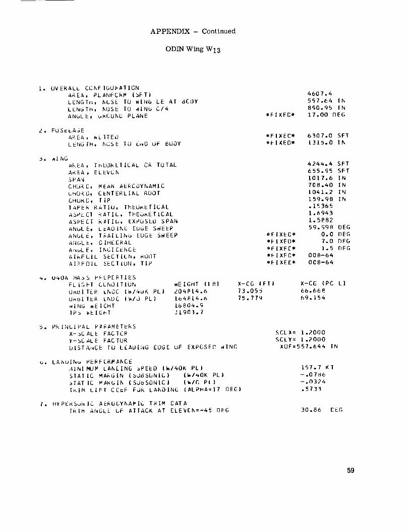
APPENDIX- Continued
ODIN Wing WI3
l$
2 •
3.
OVERALL CChF IGU£ATIGNAREA, PLANFCRP {SFT)
LENGTttt hI..,SE TU WINGLENGTH, hOSE TO 4[NGANGL E, u_CUNU PLANE
LE AT 8£0YC/4
*FIXED*
4607.4557.64 IN
8S0.95 IN17.00 DEC,
FUSELAGE
AREA, _LITEO
LENG IH, h_JSE TU E,_D UF _UOY
6307.0 SFT
1315.0 In
_I NGAKEA, ThEOKLTICAL OR TOTAL
A_EA , ELEVCh
SPA_CHJ_ C, MEAN AEkCOYNAMICCHO_L_, CI-NTERLIkL ROOT
Ct-IEJ_<C, T IPTAPE_ RAT[U, Ih.EU_ETICAL
,_SPECT kATIL, ThEURETICALASPECT KA[I_, EXPUSED SPAN
ANbLE, LEAOINC- EUGE S_EEPANGLE, T_AILING EDGE SWEEP
ANGLE, C |HECRALAm_L E, lhCl CENCEA[RFLIL SECTICN, _UOT
AIRFOIL SECIIUN, TIP
*FIXEG*
*FIXED*
*FIXFE*
*FIXFC*
*F[XEE*
424_.4 SFT
655._5 SFT
1017.6 IN
7_8.40 IN
I041.2 IN
159.98 IN
,153651.6943
[.5_82
5g._98 DEG
0.0 DEG7.00EG
i. s oFG008-64
008-64
O40A ,"IA_S PFLPERTIES
FLIGFI CCNOITIUN
O_uITEP, LNL_C (W/k.LtK PLI
U,,bITLR Lh,L)C (W/d PL)
wING _E I£HT]Pb _E I GhT
wEIGHT (I _1
204814.6
Ib4614.6
L6804._
319fl_.7
X-CG [FTI
73.055
75.779
X-CG (PC
60.66@
69.154
LI
PRINCIPAL P_AMET_RS
X-_C AL E FACICR
Y-SCALE FACTOR
U[ST,kN(_E TO LEAUING EOGE OF EXPGSEC _ING
SCLX: 1.2000
SCLY= 1.7000
XOF=557.644 IN
LA huiN,, PE_FERM AliCE
AINI MUI _ LANCING aPEED (WI40K PC)
STAI IC MARGIN (_UGSGN[C) (WI_OK PL)
_TAT IC MARGIN ISJoSONICI Iw/_ PL)
TKIM LIFT CCr_.,.FFJK LAkD[N6 (ALPhA:t7 OEGI
157.7 KT
-.07H_
-.0324
.5733
HYPErSoNIC AEKOLYkAPIC THIM CATA
[Elm ANGLE CF ATTACK AT ELEVEk=-45 DEG 30.86 LEG
59

APPENDIX- Continued
ODIN Wing W14
]. OVERALL CL;NFIGU[RATICN
AREA, PLANFEI_M |SFT}LENGTH, hESE TO ,_ING LE AT BEDY
LENGTH, bCS£ TO _ING C/4ANGL E, GRCUND PLANE
2. FdSELAGE
AREA, WEIIEDLENL, TH, I_OSE TO ENO UF bODY
3. wl NG
AKEA, TFEC_ETIC_L OP TOTAL
AREA, ELEVCh
SPAN
CHURL;, MEAN AERLJJYNAMICCHURL, CENTERLIAE ROOT
CliO&D, TIPTAPE_ RATIJ, TFEdKEIICAL
ASPECT R_TIO, IHCURETICAL
A3PECT _IIU, EXPOSEU SFAN
ANL, LE, LEADING EU_,E S_,EEP
ANGL_, TRAILING EUL, b SWEEPANbL E, CIHE£Ea, LANL,L E, I i,,CICENCE
AIRFCIL SECT IEN, R JOT
AIKrOIL SECTI{]N, lIP
_. O'.OA riASS PRCPEFTIES
FLIGHT CCND[TILN
ORr_l IcR LND6 (W/*OK PL)
u_,F_I IER tHUG Iw/d PL}
WING v_E IEHTTP_ WE fG_1
,WEIGHT ILR)208119.6
lbSlt£.o17256.2_14i 59._
5. PKINCIPAL P_RAMtIERS
A-3C_LE FACIGR
Y-SCALE FAC IO_
L)ISTANCE TU LLAU_NG EOGE UF EXPUSEC WING
O. LANOINu PcRF(_RMANCE
MI41 IVHIv LANBIi%G SPEED 4W/#OK PL )3[AT IC M_RL, IN (SJS_LNIC} (W/40K PL}:_TATIC MAKGI_ (SUOSCNIC) (WIG Pl)
TRIM LIFT CCEt FdR LANUING {$LPHA=17 OEG)
7. hYPEr, SUN IC A£kOL)YkAMIC IkIM CATA
TRIM ANGLE LF ATTACK AT CLEVCN=-_5 i)EG
*FIXEC*
50 89.8505.20 IN
894.06 IN
17.00 DEG
6307.0 SFT
1315.0 IN
*FIXF£**FIXEC*
*FIXEC**FIXEO*
*FIXEC*
4_51.7 SFT
765.28 SFT
1017.6 IN
820.47 IN
1214.8 IN
186.65 IN.15_65
1.45221.3613
63.66q DEG0.0 DEG
7.0 DEG
1.5 OEG
008-64
008-_4
X-CG (FT )
74.249
77.203
X-CG (PC I)67.75R
70.454
SCLX: 1.4C00
SCLY= 1.2000
XCF=SC5.200 IN
157.0 KT
-.0741
-.0312.5037
28.33 DEG
60

APPENDIX- Continued
ODIN Wing W15
1. UVEKALL CGKF_EUbATIONA_,EA, PL,AKFLRI" (SFTI
LENGIN, I_USE ILl aINb LE AT 6CDY
LENGTH, hCSE TO WING C/4
A,WbL E, b_uUlkO PLA_E *FIXE_*
5572.2
457.88 IN902.29 IN17o00 DEG
2. FUSELAGE
_#,bA, wt IIEC
LENGII_, hL,SE IU L,_u OF 15CL)Y
6307.0 SFT1315.0 IN
3. Wl NI;
A_,EA. IF¢£PETICAL Ok TOTAL
aREA, ELEVCh
5PAN
CPIU_ C, MtAN AEI_CJYNAMIC
L,HuKD, L. ENIEI-,LINr_ RUOTCHUKD, TIP
|APLR RATIO, [FLuAETICAL
ASPECT M_TIC, Tb_LAETICAL
A_RECT ,\ATIf3, I:XPU_bL) SFAN
ANGLE, LEAOINC Ej_I- S_EEP
ANGLE, T_AILID, G =ULJE SWEEP
ANbL E, blHEE&AL
_l_bL E, I_CICtNCE
a, lkt-(.;iL ScCTILN, KUIJTAIRFOil SECIION, lip
_FIXFB*
*FIXFC*
#FIXEC*
*FIXEC*
*FIXEC*
5659.1SFT
874.60 SFT
1017.6 IN
944.53 IN
1388.3 IN
213.31 IN
• 15365
1.2707
1.19II
66.5E5 DE(;
0.0 DEG
7.0 nFG
1.5 DEG008--64
008-64
_. 04UA i_SS PkCPE_TIES
rLi_bl CCIwDII ICN
u_,J| TLr_ Li,_DG {_IZ*OK PL)
br_,blTL_ LNUb ll_/_J PLi
_ l I'_iu :_1::i GHTF_S hEiGhT
WEIGHT liP)
211440.1
/7144(}.I
17715.5
_7_18.6
X-C_ IFI)
75.643
X-CG IPC t|
69.02771.967
5. PRI,wCIPAL P,_kAMLTERS
A-SC ALL FACICF,
Y-SCALE FACTU_
diSTANCE TO LEAUIiwG _OGE UP FXPOSEC _ING
SCLX= I..bCO(]
SCI Y= 1.2000
XOF=457.R53 IN
o. LAKL)I,_IC, PIz_FC_M_,NCE
•_INI MUM LANbING SPEEO (WI,_OK PL )
blAT IC ._IARGIN (SUb_fJNIC} |_/40K PL)
_fkl IC MA_,uIN ISU_SSI]NICI (_,I_ Pl I
l_,l,'l LIFT Cut-F FU_ LAiwDlIiG i,_LPHA=17 I]EGI
L57.2 KT
-.0725-.0316
.4462
/. I_YPE_SJN IC A_UO¥1%A_t. T@,IM CATA
TRIM AN:.,Lc EF ATTACK AT ELEVEN=-45 i)FG 26.74 DE(;
61

APPENDIX- Continued
ODIN Wing W16
I. JVEdAI_L CChFIGU_AI|GNA KEA_ PLAINFLRM {_FT)LE_'WL;IHt hCSE TL; _li'_G LE _T BCDY
LENLITH, kCSE T6 ,WING C/4A,_bLE, GROUND PLANE
Z. FUSELAGE
AREA, ,_E ITE5
LENGTH, hCSE TG Ei_(] UF EL.OY
3. Wl NbARE&, THEORETICAL Ct, TCTAL
AREA, ELEVCE
SPA._
CHu,g C, ME_,N AENCLJYNAMIC
C_iO_<u, CENTFRLIt_E _dOT
CHU,_O, TIP
IAPE_ RATIO, TPEJr, ETICAL
ASPECT _,aTIC, II-EGRETiCALaSH, C[ .aTIb, EX_LJSI=O SPANANGLE, LEAO[NC _9bE S,',,EEP
ANbLE, TffAILING _UGr_ S_EEP
A_t.L £, ClrIEgR%LAIWUL E, INCl Cc_,C=
AIRFGIL S,-CTIEN, ROUT
_I#,Fb[L SECTICN, TIP
_. U_(_h MA3S PACPEF, IIES
rLIGM! CCI_L)IT [ON
fJ:_BITtR Lt_L)C (WI_OK PL)
OK,Jl ILR LNOG (_/U PL}_ING wE iG_TTPS i,,L I GI T
_E IGHT (LH|
2UL626.')161_2£.317_7£.7
27842._
:.).Pr, INCIPAL PapA,VETE&S
X-SCALE FACIC_
Y-SCALE FACTOR,JISTAHCr 1L; LEAL;Ii_t, P_OGI CF EXPGSFC .ING
o. LANol i_b PL_hERM_NCE411,_l_U_ LANCIkG SPEE5 (m,l_.OK PL}
:_IAT IC _,_At,:GIN {Sdc. SCNLI.) (W/40K PL)
bTATIC MA_,UIN {)dDSG._IC) (_I0 PL)
TFI4 _.IFI CII_F Fdl_ LANU|I4G {_LPhA=I7 DEG}
7. HYPE_SU_IL AE_,L)bYNAWIC T_iM CATAf_l_ ANGLE CF ATT_C_c AT ELEVEN=-_D DFG
mFIXEEm
3964.2658.86 IN
889.32 IN
17.00 DEG
6307.0 SFT
1315.0 IN
$FIXEC*
*FIXEC*
SFIXEO*
*FIXEG_
*FIXEE*
313£.3 SFT
510.18 SFT
1153o2 IN4E[.25 IN677.33 IN
106.66 1N.15746
2.941£2.7793
44.703 OFG
0.0 DEG
7.00EG
1.5 DEG
008-64008-64
X-CG |FT)
71.27773.61e
X-CG (PC II
65.04667.179
SCIX= .80000
SCLY= 1.4000
XCF=AES.861 IN
t47.0 KT
-.08£t-.0283
.8772
43.87 CEG
62

APPENDIX- Continued
ODIN Wing W17
I. OVERALL CCt_FIGUI_TIC.N
ArxEA, PLANECRP {SEllLCNGTrt_ I_CSE TO RiNG LE AT BELLY
LENGIH, I_CSE TO 41NG C/4ANGL E, G_CUhC PL,_I_E
2. FU SELA_,E
A_I_A, ,iZTFCC
L_:NbIH. hOSE IU LiXD 'JF BOI)Y
3. _[N5
AKEA, TEE,JPETIC_L UR IUTAL
AkrA, ELEVGN
S P ANCHLJ_ L_, l_i-,_i_AEf4CL]YNAMIC
LtluRC, LE_TEF_LIhi ROO[CHO_J, TIP
IAVEk KAIIO, "TFEU_,ETICALASPrCI _,,_IlL, "TFcukETICAL
A_PELT K#TIL, EXPuSEO SFANAN_LE, LEAUIXb _U,,,,E S^EEP
AhI,.,LE, TRAILING EuCE 5_EEPAiq(,L _., [;IHEt;EALA,wbL E, Ih, Cl CLNCE
AIr,FCIL ScCTICN, r_OL'[Ai_,FCIL _ECIIL;N, llP
_. O_0A ;',ASS FhCPE_,IIES!i-L lu Fl CCNDITICN
U_,UI TEl-, LNCG (_,I',OK PL)
U_bI I E_ Lr,,E_ (_/u PL|,_ I N(;, ,_ E I O11TP3 _EIGI T
_E IGHT ILt_I
2,) 5210.0
t65210.0Id023. 731080. 3
_. PKINCIPAL PAI_AMETE{,S
x-:)C ALL FACTO_
Y-SC AL E I- AC TO_.u|STANC£ TO LEAOIr_G dOGE OF EXPOSED wING
c,. LAND|._6 PhRFI:P,M/_NCE
AI.IIMUM LANCINC, SP_:EO (I,IQOK Pl )
bTATIC NAFGIN (SJbS6NIC} (WI40K FL)
_,T_4TIL MARGIN (SJbSIJNIC) (wlO Pt}
T,,IM LIFT CLEF FLJK LAh,DING (ALPHA=]7 BE(;)
7. lIYPE,',Sur_[c AEAuI)YhAMIL. Tv,IM CaTA
T_,I_,IANGLE CF ATTACK AT EL EVCN=-45 DEG
*FIXEB*
4527.0
600.61 IN88R.bq IN
ll. O0 DFG
6307.0 SFT
1315.0 IN
*FIXEC*
*FIXE£*_FIXEC*
_FIXE£*
*FIXF[*
3£24.1 SFT637.73 SFT
1153.2 IN576.57 IN846.07 IN
133.32 IN.15746
2._535
2.22J551.050 DEG
0.0 DEG7.0 DEG1.5 OEG
00_-64008-64
72.199
74.709
X-CG (PC L)
_5.e87
68.178
SCLX= I.CCO0
SCLY= l.eOO0
Xt']F=600.614 IN
143.2 KT
-.0800
-.0277.7534
34.12 DEG
63

APPENDIX- Continued
ODIN Wing W18
I. OVEdALL CCNI'IGU_AIIONAREA, PL_NI-LIRM ISFT}LENGTh,, hbSE TU _ING LE AI BCI]Y
LENGTH, b,CSE It] _'ING C/4
ANGLE, GRUUND PLANE
2. FUSLLAGEAREA, _NETTE0LENGTH, I_USE TO rNU OF BODY
3. Wl _G
AREA, TI-[OkETICAL OR [01AL
AREA, E LEVCI_
SPAN
CHURL, VEAN AE_UDYNAMICCttLjRO, CENTE_LINr RLJOT
(.HURL, TIP
IAPER RAIIU, IHEURETICAL
ASPECT K,_IIO, I_EURETICAL
ASPECT kATIE, EXPUSE5 SFAN
ANGLE, LLAUIIXC EOuL S_EEP
ANGLt:, TI_AILIhC- tUb_- S_EEP
A_wL_LE, C [hECk_L
ANu,L E, INCIEENC_
AIRFOIL SECTICN, K JOT
AI#FLIL SECIICN, TIP
4. Og. OA MASS PF, LPERTIESFL IL, HT CCNOITIEN
OE61TER LND6 (,_I_UK PLIOk_I TtR LNuC- {_/J PL}
_ING ^E IG_TTPS _E IOl-T
_E I(-HT I[ltlZOSB4t .g
106841 .g184£8.3
3_;27.6
b. PRINCIPAL P_kANETERS
A-SCALE I,AC 1CR
Y-SCALE FACIOR
OtSTANCt TO LEAL)I,'_G EUGE OF EXPUSED ,I:,IG
6. LANUING PERFCF.M_NCE
,,IiNl/'UP LANLINb bPEEO (WI_OK PL }
STATIC .,4_kbJN (SUbSuNICI (kl40K PLI
STAT It..MA_.bIN (SUbS6NIC| I_lO Pl. )
TKIM LIFI UUEF l,d,_,LANDINC- IAI PHA=I7 I)EGI
_'. HYPE_:_U,_IC &EKUUYNAM,_C IkIM CATA
T_,IM ANGLE CF ATTACK AT ELEVCN=-45 F)EG
*FIXFO*
508g.8549.t5 IN
8_4.84 IN
17.00 DEG
6307°0 SFT1315.O IN
*FIXEC**FIXEC**l,IXEC_
*FIXEO**FIXEC*
4708.9 SFT
1_5.28 SFT
1153.2 IN691.88 IN1016.0 IN
!.59.98 IN• 15746
1.9612
1._ 52(J
56.035 DEGO. 0 DEG
7.0 I]EG1.5 DE[;
(108-64
008-64
X-CG |FTI
13.3437_.069
X-CG {PC L}
66.931
6S.419
SCLX= 1.2000
SCLY= 1.4000
XOF=549. 145 IN
142.1. KT
-.0779
-.0306
._490
29.53 DEG
64

APPENDIX- Continued
ODIN Wing W19
i. (]VER,_LL CUNFIoU.ATIUN
A_CA, PL_NFEBP (_l-T)
LENGIH, NCSE TO ,_INb LE AT 6[0Y
LrNGTH, ELSE To 41NG C/4
ANbL i, G_UUN0 PLANE
2. FJSELAGE
AREA, _[TTEBLEIWL,Iil, KCSETC 'nO UE BODY
3. _I NO
ArKEA, Tl Lu_ETICAL GR TGTAL
AREA, LLEVUK
SPA'_
CHO4D, _EAN aERULJY,_AMIC
CHJ_C, t_NT6kLla\h RUU[
(.,HU,_.O, TIP
T_aPEk RaTiO, II FURETICAL
A3PECI _w_TIL, TkdLJEETIC,aL
ASPLCT ,',aTIC, EXF'uSLL) SPAN
ANGLt:, LEAOINC EOul: S_,EEPANUL I-_ T_AILING cuUE J4EtP
AN,,L E, CIHECkAL
A,,_taLL , Ib, CI LENCE
alRk(_iL .<ECIILN, ROUT
AIffFC|L SECTICN, l IP
4. O,*bA i"iASS P,_CPEbTIES
FLI,,HI uCND ITIUN
d,,81TLF, LNDG lSI4UK PL )
Lh',tSlTeR LNDC (_/O PL)
,, l,_b ,,EIGHTTP:_ _EIGFT
_E IGHT ( LBt212508.6
t7:,' 508.618821.437:,8l .2
b. PI-,INCIPAL V_i4AMET,kSX-bC ALE FACICR
Y-St. ALL FACTOR
DISTANCE TC LEADIt,,G EuGE OF EXPCSFD ,_ING
o. LANJINu PEKI-Ew, M,AKCE,,iT_IINUM LANCING SPEEO (WI_OK PLI
JTAI JC MA/,GIN (SdLtSUNI£,} |W/_(]K PLt
alAT It., M_r_GIN (SJdSLINIC) (W/L] PL)
Tt<14 LIFT CLEE F,iR LANDING I_LPEA=I7 DEG)
7. HYPE,-,3UNiu AI:I,OLYIXAPIC TRIM {SARA
TRIM ANbt.E LF ATTACK AT ELEVCN=-45 DE(;
*FIXFC*
5652.6
498.90 IN
902.21 IN
17.00 DEG
*FIXEC*
*FIXED*6307.0 SFT
1315.0 IN
*FIXEC**FIXED**FIXE_*
*FIXF£**FIXEB*
5493.7 SFT
892.82 SFT
1153.2 IN
807.1£ IN
1185.3 IN
186.65 IN
.15746
t.6811
1.588259.998 8EG
0.O DEG
7.0 DEG
1.5 DEG
008-64
0C8-64
X-CG IFT)74.636
77.605
XICG (PC L)68.111
70.820
SCLX= 1.4000
SCLY= 1.4000
XFIF=4C 8.£03 IN
141.4 KI-.0752
-.OBll
.5711
27.36 DEG
65

APPENDIX- Continued
ODIN Wing W20
1. OVERALL CONF|(.=U_ATION
A,_EA, PL_NF(.RM {$FT)
LENGTH_ kOSE TU WING LE AT BCDY
LENGTH, t_bSE TO 41NG C/4
ANGLE, L,ROUND PLANE
2. FUSELAuE
AREA, _ETTEC
LENGTH, _{JSt 1{] EIwD 01: BCDY
3. _I hG
AREA, TI_EOKETICAL Ok TCTAL
ARIA, ELEVEN
SPAN
CHJRE, MEAN _EREJJYNAMIC
CHURLS, CENTERLIt_E R(JCT
CtIL_RC, TIP
TAPE, RAIIO, TIEJ_,ETICAL
ASPECT RATIC, THEORETICAL
A3PECT t,,ATIIJ, EXPuSEO SFAN
ANGLE, LIzAOING EOoE SWEEP
ANGLE, TRAILING EuGE SWEEP
ANGLE, CIhEr RAL
ANL, L E, IhCILENCE
AIRFOIL SECIICN, KUDI
AIRFLIL S_CT_(JN, TIP
•,. U40A HA_S PROPFkTIES
FLIbHT CCNDITICN
OR3ITER LNDE (WI_UE PL)
dR6t TER LNDG IW/d PL}WING hEIGHT
TPS _,EIGFT
WEIGHT (tP)
2lbl_8.I
IT6 Ig8. I
lg2 =_3. I
,e0839.0
b. PkINCIPAL FA_AMETERS
X-SC AL E FACILR
Y-SCaLE FACTCR
OISIANCE TO LEADINu r-UbE OF EXPCSEC wING
u. LAKDING PERF£RMAb, CE
MINIt.ldP LANCING _PEED (kI4.0K PL)
STATIC MAKGIN (SJBSONIC] (WI40K PL)
STATIL, MARGIN (SUbSCNIC) (WIG Pl)
IklM LIFI" CLEF FD_ LANDING (_LPFA=]7 F)EG)
7. _YP_,_S(JNIC _E_ULYhAMIC TRIM CATA
T_I=_ ANGLE (IF ATTACK AT ELEVCN=-4.5 DEC,
_FIXEC=
6215.4
451.62 IN
912.54 IN
17.00 DEG
*FIXEC*
_FIXEC_
6307.0 SFT1315.0 IN
*FIXEC**FIXED*
*FIXEfi**FIXE[*_FIXEC*
6278.5 SFT
1020,4 SFT
1153.2 IN
922.51 IN
1354.7 IN
213.31 IN
,15746
1.470q
1o_897
E3.1_6 BEG
0°0 DEG
7.0 _EG1.5 DEG
00R-64
008-64
X-CG (FT)
"t(:. 106
7q. 34.b
X-CG (PC L)69.453
72.410
SCL;_= 1.6000SCL _1= 1.4C00
XOF=4.51.E IE IN
141.4 KT-.0735
-.0314
.5C86
26.10 LEG
66

APPENDIX- Continued
ODIN Wing W21
I. OVI-RALL CCNF 16UR/_TICN
AREA, PLANFLkP (SFT)
LENGTH, _OSE TO NING LE AT BGDY
LE,wGTH, hi]SE TO HING C/4
ANGLE, GRCUND PLANE
2. Fd SELAGE
AREA, w E.TTLD
LENGTH, NLS_- TU cNO UF BOdY
3 • al _G
AREA, TFEUKETICAL UR TUTAL
AREA, ELEVCK
SPAN
CHU_ O, _EAN AEf_UOYNAMIC
CHUR, C, _.¢wIEF, LINE KUGI
bhU,:LC, TIP
[APE_. RAIIU, IFEdr_TICAL
ASPECI K_TIC, "THEdRETICAL
A_PECT KATIO, IzXPuSEU SFANANL, LE, LLAOINE Edge SWEEP
ANGLE, /RAILINC EUGE SWEEPANGLE, L;[HEOgAL
ANGLE, II_CI LENC_
AI.kFCIL _ECTICN, kUOT
AIkF6IL _ECTIbN, TIP
4. d40A MASS PF[PcFIIES
FLIGHT CCNL)IT ICN
O_I TER LNUG (h/'.o& PL)
UkSI TER LNO_ Iiw/G PLI
IP_ hEIGFT
WEIGHT (LB)2U 4':;2 4 ._Lo4%2_.. 5
L933o.q/948I .E
X-CG IFT}
ll.&Tl
73 .P09
5. PKINCIPAL PAGAMETEkS
_,-SC AL E FACICk
Y-b{. _L L FAC TCg
UlSTANCE TO LEAL)ING t:ObE CF EXPOSEC WING
o. LANL}II_ PERFLr, M4hL.E
_tINIMUM LANCING SPEEO |H/40K PLI
STATIC MA6GIN ISU8S[_,_IC} I,_140g FI_)
STATIC MARGIN ISbbSCNIC) {W/C PtI
IKIM LIFT CL;EF [Jck LANDING I_LPHA=I7 I)EGI
7. hYPERSONIC ALROLYNA_IC Tr_IM [;ATA
TRIM ANGLE LF ATTACK AT FLEVEN=-45 DEG
*FIXEC*
4285.8
654,60 IN
8q1,05 IN
17.00 DEG
*FIXEC*
*FIXEC*
6307.0 SFT
1315.0 IN
_FIXEE**FIXED**FIXFC*
*FIXF[**FIXED*
3451.9 SFT
583.07 SFT
1288.8 IN
453.00 IN
664.72 IN
106.66 IN
.16045
3.3416
3.1764
40.892 DFG0.0 OFG
7.0 nE_1.5 DEG
008-64
008-64
X-CG IPC L I
65.22367.3t)6
SEt.w= .80000
.£CL Y= 1.6000
XCF=_.=4.398 IN
136.3 KT-.0_06
-.0287.9438
39.£3 EGg
67

APPENDIX- Continued
ODIN Wing W22
I. OVERALL CCNFIGU,_TICN
Aw, EA, PLANFCRM (',IT)
LENGTrl, huSE TO WING LE AT BCDYLENGTH, I_OSE TO ,_INb C/4
ANGLE, G_CUkD PLaNt
2. FU SELA,;t-
AREA, WEITEDLENGTH, t_l]SE TO [i_D uF BUOY
3. WING
AkEA, THELREI ICAL Ok TOTAL
AREA, ELEVUh
SPAN
CHOR b, MEAN AE_LOYNAM|CCiibRE, CENIFe<Llhc _UGTCtiOR _, T IP
TAPt-F, RATIU, TF_U_ETICAL
ASPECT _ATIC, Ih_-URETICAL
ASPECT _TI_, EXPuSEG SPAN
ANGLE, LEADINC EO_E SmEEP
AIWUL_t TNAILIhG EUGE SWEEP
A[qbL iEt C II_EL]F AL
ANuL E, IhCILENCE
AI_FI. IL SECI IL_, _UuT
AIkFCIL SECIIUN, TIP
4. U40A MASS PF(PEF, IIES
FL Iuhl CLJNOIT ICN
ow,6i TLR LNOC {W/,UF, PL)
U_,U[ T#JK LI',UG (h/d PL)
_z_G _E IEHT
TPS _c IGHT
WEIGHT ILl31
20E_64.9I08_64.9
19C42.3_3116.7
b. PF,INI. IPAL ParAMETERS
X-SCALE FACTUR
Y-SCALE I ACICIK
DI:)TANCE 10 LEAOI,_G _OGE CF FXPCSEC WING
O. LANOIi_IG PE_F[t_MAhCE
MI,_I MUM LANCIKL, _PEEO ( _I',OK PI )
STATIC MAP ulN (SJL_SbNIC) (WI4LIK PL)
bT_,l IC MA_C, Ih (SUbSb_IIC) (_/CI PI)
[_,iM LIFT CCEF F JR LANDING (ALPHA=f7 DEC;)
7. hYPE_SL)NIC A_:r,LJLYkAMLC TF,IM DATA
Tr',IM ANGLE EF AII ACK AT t:LEVCN:-45 BE(],
_'FIXE(]*
4_29.0
5_B.27 IN
8_4.0g IN
17.00 DEG
6307.0 SFT
1315.0 IN
*FIXEC**FIXFC*
*FIXED**FIXE[*
*FIXEC*
4314._ SFT
728.84 SFT
12R8.8 IN
566.25 IN
B30.8_ IN
133.32 IN
.160452.6732
2.5411
47.268 OEG
0.0 OEG
7.0 DEG
I._ DEG
00_-_4
0E8-64
X-EG IFT|
72.478
7_,.ggg
X-CG I PC I |
66.141
68.442
SCLx= 1.0_00SCLY= 1.6000
XOF=GqS.26_ IN
132.0 KT
-.0_21
-.0287.8204
3L.79 EEC,
68

APPENDIX- Continued
ODIN Wing W23
L. OV_-RALL CLhFIGURPTIL_
AREA, PLA,wI=(.F:M {_.I-T)
L_,,_GIrl, t_[]SE TU ,WING LE AT BCF)Y
L_NGIH, t_CSE It] WiNG C/4
ANGL E, GRCUhL) PLANE _'FI XFO*
5572.2
54_.09 IN
904.07 IN
17.00 OEG
2. FUSELAGE
A_EA. _,ETTt-L
LENC.,Th, N_Sr- TO ENU OF bUOY
6307.0 SFT
1315.0 IN
AKt.A, IHFO_EIICAL UR /01AL
_EA, ELEVGk
S P AN
CHu_ t_, MEAN AE_COYNAMIC
_,HUFCIS, CENTEkLII_: _bOT
CHE2_,_, 1 IP
IAPE_ RATIU, TI-EO_ETICAL
ASPECT rK_llL, THL_U_ETtCAL
A_PECT ,<_TIC, EXP,..JSLL) SPAN
AI'_UL E, __rAO l_t_ EJGE S,WEEP_L,,LL, Tt, AILIN_ dUOE _V,E_.P
Ai4OL E, LIHEEH_L
A:_UL L, [_L,I CtNCE
AIEeCIL -_CTILN, _,UUI
AI,KFLIL SECTICN, lIP
*FIXEE*
_FIXEC**FIXEC**FIXEE*
*FIXFE*
5177.g SFT
874.60 SFT1288.8 IN67q.50 IN
£q7.O7 IN
159.98 IN• 1e045
2.22/7
2.1176
52.409 OEG0.0 BEG
?.00EG
t.5 OEG
00_-64
008-_4
4. O_OA MASS PHLPEhTIES
F L I,.,.I"T CCND IT IC_dP.BLT_ LNDC (_,/._OK PL)
O,_OL Tcn LNL)G (W/O PLI
,.,lNG _ E I (;I_T
I25 _r lb_T
wEICHT (LH|2/ZSbS.(l
/9989.230-_E2 .E
;w-CG {FT|
73 .??_
7_.415
X-CG (PC L}
67.2786£.7A£
b. Pt-.INCIPAL PARAME|ERS
&- _C/4L L_ FACIO_
Y-SCALE fACT[JR
diSTANCE IC LEADING EDGE UF FXPCSEI) ,WING
SCLX= 1.2000
SCLY= 1.6000
XOF=54g. OgO IN
O. LANOINu PLRFCKMANCi:c.'_l,_IMu_ LA_blNG SPELl5 (W/,,OK PLI
31AT it. PARuIN {SJoSL]NIC) {_I40K PLI
_.TAT [C MA_L, IN (SJI_SGNLC} {WIO PL)TFIM LIFT CCEF _':_.J_LANDING (ALP_A=I/ DEG)
130._ KT-.08 iT]
-.O324.7113
7. HYPE_.uNIC AE_-,ULYNAM|L. TRIM DATA
T.-,.IM ANGLE CF ATrACY, AT ELEVCN:-45 DEG 28.05 BFG
69
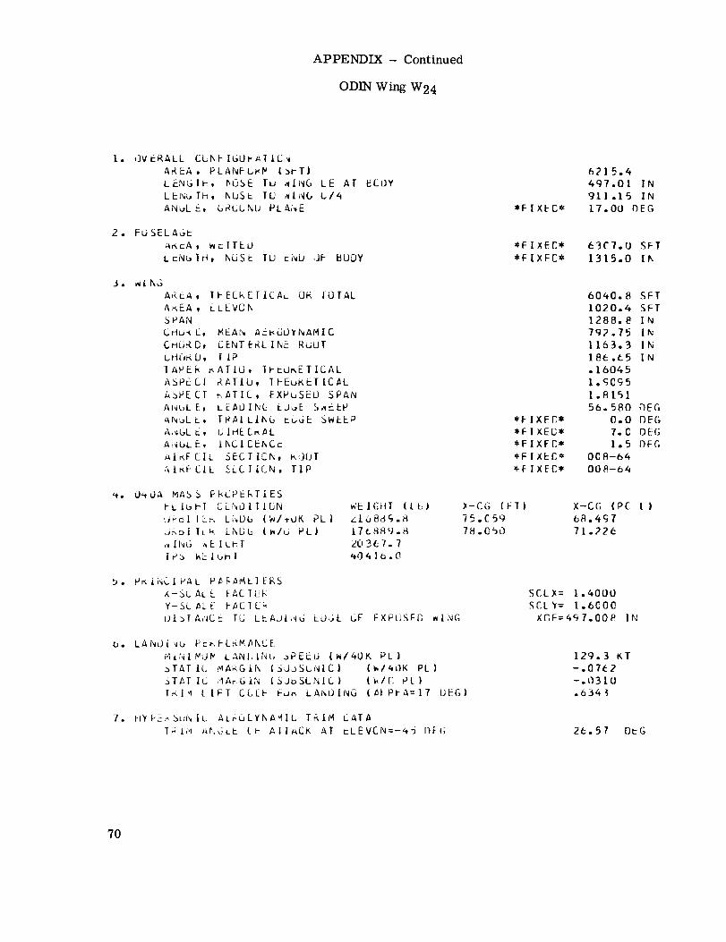
APPENDIX- Continued
ODIN Wing W24
[. OVERALL CLKFIGUP_IICN
AREA, PLANFbAP I_I-T)
LENGTh, l_OSE IU _ING LE AT UCOY
LEI_,.,Ih, KEJS_- TU ,_t_(.,{./,_
ANL,L E, b_UUNU PLAhE
2. FU SEL AG_-
_r.EA, _ElTEO
LcNbIH, NOSE TO CNU dF BODY
3. ,_ING
AREA, IFECREIICAL OR IOTAL
AREA, ELEVCK
SPAN
Crlu_ C, MEAN AFI<dL)YNAMIC
CMUR, D, CENTtRLINC R_UT
CHtJK D, I J.PIAPEF_ _ATiO, 31-tUr, ETICAL
ASPECI ,AATIb, _I-Eu_,ET[C_L
ASPECT ,,ATIC, EXPuSEO SPAN
AI_uLE, LEAOIN_ EO_E S^6bP
ANJLL, TRAILIKG cuGE SWEEP
,I,_GLL, L;|HE [_/_L
A!_GLE, iNCI CEI_Cc
_IKFCIL SECTICN, k,]OT
AIr_FCIL _LCIICN, TIP
,+. C)40A MASh FhC2E[_TIES
I-L IL,kl CCNOITICNdFol ILr, LiwL)_ (N/tUK PL|
LJ_DI ILk LNDb l_/d PL)
[P.b I_L lbhT
WE lGtiT (t_.l
Z168d£._
L7LSFIg._
20367.7
'*04 Io .O
b. Pr, iI',CIVAL P_F_MLIERS
X-bL. ALL I-ACIUFL
Y-St _LE F#CIL_
_)I_TA,'_CE TU LEAUi _U _OGL LIF FXPflSFC _ING
O. LANL) I wu FcEFCFMANCE
r4,_hl/%IP LANI;INb .)PEEL) (W/kOK PL}
_TATIC MAkGII\ (SJL_SL, NIC} {W/_{}K PL)
._TATIC 'IAr:GIt_ |SJbSI_NIC} (_/C PL)fr, l_l LIFT CCtF t JA LAhOING (al Pl A=17 UEG)
7. HYF__r, bLJN|C ALruCYKA,4It T_IM CATA
TXi"i A_.U:LE (t- AIIACK AT _LEVCN=-4_ DFG
*F IXEC*
6215.4497.01 IN911 .15 IN
17.00 fSEG
63C7.0 SFT
1315.0 II_
*F I X F P,*)F ] XEC*
*FIXFC**F IXECX,*FIXEC*
60_0.8 SFT1020.4 SFI1288.8 I N
792.75 IN1163.3 IN
186.65 IN• 16045
I._0_5
l.Rt5]
56. 580 nEG
0.0 DE(;
7. C OEG
1.5 OFG008-64
008-b4
)-CG IFT)75.£59
78.050
X-CG lPC I)
7L.226
SCLX= 1.4000
SCL'(: 1.6000
XGF=4£ 7.00P. IN
129.3 KT-.07e2-.03 10
.634
26.57 DiG
70

APPENDIX- Continued
ODIN Wing W25
1. OVERALL CCKFIGURAIICN
AREA, PLANFCRM [3FT|
LENGTH, hOSE TO WING LE AT 80DY
LENGTH, hOSE IG _ING C14
ANGLE, GRCUND PLANE *FIXEC*
450.04 IN
923.35 IN
17.00 DEG
2. FUSELAGE
AREA, W_TTEU
LENGTH, MJSE TU END OF EOUY
6307.0 SFT
1315.0 IN
3. Wl NL;
AREA, TFEORETICAL OR TOTAL
AREA, ELEVOh
SPAN
CHORC, MEAN AEROJYNAMIC
Cri3_D, CENTERLINE RUOT
CrIORC, T iPTAPE, RAIIO, TF_ORETICAL
ASPECT R_TIb, THEORETICAL
ASPECT RATIO, EXPUSEO SPAN
ANGLE, LEADIN6 EOL,E S_EEP
ANGLE, TR_ILING EDGE SWEEP
ANGLE, DIHEERAL
ANGLE, ih,CI LENCE
AIRFCIL SECIlCN, ROOT
AIRFGIL SECTION, TIP
*FIXEC=
*FIXEC**FIXEC**FIXEC*
*FIXEC*
6_03.8 SFT
1166.1 SFT
1288.8 IN
_06.00 IN
1329.4 IN
213.31 IN
.16045
1.670R1.5882
5g.998 DEG
0.0 DFG
7.0 DEG
1.5 DEG
008-64
008-6_
4. 040A MASS PRdPERTIES
FLIghT CCNDITION
URJlIER LNOG IWI_OK PL}
ORBITER LNDG IW/O PL)
_ING _EIC_T
TPS WEIGHT
WEIGHT (LBI
220_4g.2
L80_49.2
2076g.]
X-CG iFT)76.612
7(J .87g
X-CG IPC L)
6g._14
72.8_6
5. PRINCIPAL PARAMETERS
A-SC _L E FACTOR
Y-SCALE _ACTUR
DISTANCE TO LEADING EDGE OF EXPOSEO WING
SCL_= 1.6000
SCLY= L.6000XOF=450.039 IN
6. LANUI,_G PERFCRMAI_C£
MIWIMUY LANCING SPEED (W/_OK PL)
STATIC MARGIN {SU_SIJNIC| IW/_OK PLI
STATIC MARGIN (SUaSGNIC) [k/O PtI
[RIM LIFT CCEF FOR LANDING (ALPHA=T7 DEG|
129.0 KT
-.0745
-.0312
.5678
1. H_'PEKSUNIC AERL]DY_AMIC TRIM 5ATA
TRIM ANGLE GF ATTACK AT £LEVCN=-_5 DEG 25.58 DEG
71

APPENDIX- Continued
ODIN Wing W26
I. OVERALL CONFIGURATION
AREA, PLANFORM (SFT)
LENGTH, NQSE IO_IT_G [£ hi-BODY-LENGTH, NUSE TO WING'S-f4
ANGLF, GRQUND PLANE
37_-.-9 - --
...... _SB_, 42-IN ---
_FIXED* 17.00 DEG
AREA, WETIED ........... a_TI'XED# 6307,0 SFT
LE'NBTFIV_E-_-OT r BODY - _nq:'I%qE__, O_ ....
3° WINGAREA, IHEOREIICAL OR IUTAE ......... 3_3T0.9 b_-
- AREA, ELEVON .................. _--911_Sl:'T -" _F49_ _0-- IN-- - -- SPAN •
........ _R_ _EA3_-A_YTqAF, fIC ........ _ I'_ IN ....
...... C HI_--C__NE "ROrFT ........... ?_Z_ -II_ --
CHORD, Tie Iiq,99 IN
.... T A_-R__CAI_ .......... .151-31- -
ASPECI PAl I0 #-__O-- SPAN .................... ] ,_t+i-i -
..... AN_FT_LEADING FOC_ _WEEP ............ _T+_7c)6 i_F_ -
....... _N_RAILING -EDGE _WEEP ........ _F_[XEh._ " - 0,,00EG -ANGLE, DIHEDRAL '_FIXED _ 7,0 DEG
-- ---A-_F_- INCIDENCE ........ _IXEO* l,q OEG
- -A-I_Fh_IL-- _TION, --_ - " _rIXEq3* 008- 8_ "00_t-64
_, 04OA MAS_ PROP'ERTIES
FLIGHT CONDITION WEIGHT (L_) X-CG (FT) X-CG (PC L)
ORBITER LNOG (W/40-K-P-C) i-_;-_ " 71,_12 6_,16o
ORB ITER LNDG" (-w_L) _8_- 7 3-,,835 ..... _/-,-_0
..... Q_ WEIGMI ......... 1537F_.4 " _ .......
....... _ %_:ri_-- _ ....... 267_1, 3 - .
5° PRINCIPAL PARAMETERSx-SCALE FACTOR S_-L_X_ .qO_O
Y-SCALE FACTOR SCLY= I.I0_-0
DISTANCE _0 LEADING _'DGE-'OFErXp_ WING XOF=642;360 I-NT-----
6. LANDING PERFOHMANCEMINIMUM LANDING SPEED (W/kOK PL) t_7.6 KT
......... _ATI_-M_F-G]N_URSONIC) (W/4OK oL) ....... -,-0_7 .....
- _TATI C--CA_G IN TSUBSON I C ) _W-/TP LT ................. :, 027A _ ....._- TRiM L|FT-COEF FOp LA_DiNG---(AL-P-Q-A=I_EGY ...... ,6916
7, HYPE_SONTC AERODYNAMIC T_IM DATA
TPlM ANGLE OF ATTACK AT ELEVON=-_5 DEG 44.0_ I)EG
72

APPENDIX- Continued
ODIN Wing W27
Io OVERALL tUN_IUVMAIION
ANGLE, GROUND PLANE *FIXED* 17.00 DE6
2, vUsET--A_E - ............................." ApE_..-w_'r_D ............... TFFIXE_-- 6307;0 S;T
iENG?FF, NOSE TO Er_D OF BODY _FIXE't')*-- I315.0 IN
3. WINGAREA, THE_RE-TICAL OR TOTALAREA, EL E_ON
SPAN "- -cHORn, _EAN'AEI_DYNAMIC
_ORn, CENITRLII_ROT_T_HUR_, TIP
....... 33S6. g-SFT532.q6 SFT
- - I08_.4 IN........... 5P4.63 IN-
.... 770.74 IN11W.99 IN
TAPER RATIO, THEORETICAL - .15_68ASPECT PATIO, THEORETICAL - 2,4371
..... ASPECT _A?IO, EXPOSEh-SPAN .... 2.2940
- aNGLE, LEADING EDGE SWEEP 50.172 DEG
ANGLv, TRAILING.EhGE SWEEP- :FIXEO_ 0.0 DEG_NGLF, DIHEDRAL *FIXED* 7.0 DEG
.... ANGLF, INCIDENCE ....... _FIXE_* ..... 1.5 DFGAIRFnlL SECTION, QOOT *FIXED* 008-b4AIRFOIL SECTION, TIP *FIXEi]* 008-64
4. 040A MAS_ PPOPE-RTIESrLIG_I CONDITION WEIGHT (Lq)
O_BIYER LND_-(_/40K PL) 201665.gORBITER LNDG (W/O PL) 161665.gi#ING WEIGHT 1701S;6TmS wEIGHT 28544.3
X-CG (FT) X-C_ (PC 'L)
73,gq6 67.$27
S. PRINCIPAL PARAMETERS
x-SCALE F_C_OR
- _I_TA_CF IO-LEAOiNG EDGE OF EXPOSEn WING
SCLX= .gO000
SCLY% 1.3000XOF:630.360 IN
6. LANDING pERfOrMANCEMINIMUM LANDING SPEED (W/40K PL)
STATIC MABGIN {SUBSONIC) (W/40K oL)--_-TATIC MABGIN fSUR_ONi-C) (W/O PL} _ '--YR-I_-L-I_T-C_IEF F'D_ LANDING-(ALPHA=I? OEG) -
150.8 KT-.0_0_
-.025_.77_Q
7. HYPERSONIC AERODYNAMIC TRIM DATATRIM ANGLE OF ATTACK AT ELEVON:-w5 DEG 40.36 F)FG
73
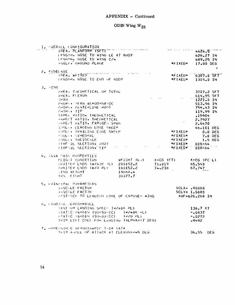
APPENDIX- Continued
ODIN Wing W28
I. (_VEF_^.I_L cONPIGUPATION
...... _DB A ,-PL ANFOt_r4--(SPT) ....................................... 4426._ ........
I _NGrH, NOSE TO WING LE AT BODY
I ;NG_H, NOSE TO WING C/4
^NGLF,-GROUNO PLAHE
2. FUSEI ,_GE..... _I_A, W _ T TED--............
I FNGTH, NOSE TO E_,,F)(_F RODY
626,27 IN
889,25 IN
*FIXED e 17.00 DEG
#
*_IX_b* .....63-O).O-SFY-
*FIXED* 1315.0 IN
3. I,_I NG
t',..'EA.T_FORETICAL OP TOTAL
_EA. _ EVON
=-_P AN
C_OR':. :'_FAN AENL)F)YNA'.IIC
cHOP,,. CENTE_LINE POql
cHOR,:, rip
TAPE b- RATIO. IHEOPETTCAL
'_PE,"T _ATIO, THEn_ETICAL
_,_PE('T _ATIO. FXD/)SE,)SP-AN
_:V_L_-, L.EAOING EI)_E _wEE p
,,,',_r_L_.trAILING E:)GE SWE-_P
',:_GL; , :JIHED_AL4:IGL_ , '_NCIDENCE
_IRF:;IL SECTION, MOOT
, IRF:,IL SECTIUN, TI p
3707.2 SFT
614.95 SFT" 1221-;0 iN ....
513.96 IN
754.43 IN
119.99 IN
.15904
2.7927
2.6470
4b.lOl OEG
*FIXED _ 0.0 DEG
*FIXED* 7.0 DEG
"FIXED" 1.5 DEG
*FIXED* 008-64
*FIXED* 008-64
a. :_.'JA '_AS _- PQOPEF_TIES
rl IO_,l CONDITION
,)FYr_IT[.P LNDG (W/4qK -'L)
;_,JFIITEP LNF)G (w/O PL)
.ING WEIGHT
TPS ,E It,HI
wEIGHT (L,_)
205152.2
105152.4
30377.7
X-CG EFT)
71.819
7u.238
X-CG (PC L)
65.540
67.747
5. _PINcTP_I Pc,_tAMFTER_
x-SC_,LE FACTOH
Y-SC_LE FACT¢)R
_,tST,,NC_- TO LtAUIrir, klF)GE OF EXPOSE,_ _ING
SCLX= .90000
SCLY= l.SO00
%OF=626.268 iN
h. i Ai,_Dt',G ,,EP;O_MANCE
'_[NI,"UM LANDING SPEE,, (w/40K PL)
,._I_T;C vAF_GIN (5UqSO',,IC) (w/40K ,JL)
<TATtC .'A_GIN (SU_SOdIC) (_/0 PL)
TuIM LI_I COEF F()p L.i'_l)INb (ALPHA:!7 DEG)
138.7 KT
-.0837
-.0272
.8492
7. _f_E,_%ON;C AFrO )Yr_MIC I,-'IM i)Ar_l
t_I_ ;i,lqLr ()F" /_TTACK AT ELEVUN=-_S BEG 36.55 DEG
74

APPENDIX- Continued
ODIN Wing W29
]. ; OVERALL CONF]GURATICN
AREA_, PLANFORM (SFT)LENGTH, ...............................................
LE _NG.T_H__NQSE TO.WING C/4 ......
..... ANGLE_t. GROUND_ PLANE .............................
4587.3
580,,70 IN
892°35 IN
*FIXED* I7°00 DEG
AREA_ WETTED *FIXED* 6307°0 SFT*FIXED* 1315.0 INLENGTH_ NOSE TO END CF BODY
3. WING
AREA, TPEORETICAL OR TOTAL
AgEA, EL EVON ..
SPANCMCRC, MEAN AERCCYNAMIC
CHORD, CENTERLI_E ROOT
CHCRD, TIP
TAPER RATIO, THEORETICAL
ASPECT RATIO, I;FEORETICAL
ASPECT RATIOt EXPOSED SPAN
AN G L E 1ANGLE,
ANGLE,
ANGLE,
LEADING EDGE SWEEP
TRAILING_ EDGE SWEEP ..........
DIHECRAL ...........
INCIDENCE
.............A_[_R_F_Q_IL_@EC__!_I0 N,
4102.9 SFT
651.40 SFT
.................... L0_85.4 .IN641.21 IN
942°0 1 IN
146.65 IN
.15568
]..g940
....... _t, .e_769_ .....55.692 OEG
*FIXED* 0.0 OEG
*FIXED* 7.0 DEG
*FIXED* 1.5 DEG
AIRE_IL SECTICN, ROOT *FIXED* 008-64
TI P ................................................* F! X_E.D,...._QOB-6__ ....
4. 04OA MASS PROPERTIES
FLIGFT CONDITION WEIGHT (LB} X-CG EFT) X-CG (PC LI
ORBITER LNDG (WI40K PL) _05097.B 72.652 66.301
ORBITER LNDG (WIO PLI 165097.8 75.274 68.693
................ .w___],__ WEIGHT ].7403.Q ...........................................TPS WEIGHT 31588.8
5. PRINCIPAL PARAMETERS
X-SCALE FACTOR,
Y-SC ALE FACTOR
........ ___DLS__T_AN_C_E__T_OL.E._A_0 iNG
SCLX= l.IO00SCLY= 1.3000
EDGE O_XPOSED _W_I_NG...............X_O_F_=580, 70.4 IN .....
6. LANDING PERFORMANCE
MINIMUM LANCING SPEEG (WI40K PL|
STATIC MARGIN (SUBSONIC) [WI4OK PL)
STATIC MARGIN (SUBSONIC) (W/O PL)
........... TRIM LIFT CGEF FOR LANDING (ALPHA=T7
150.3 KT
-.0818
-.0327
DEG} .................. .6537 ...........
7. HYPERSCNIC AEROCYNAPIC TRIM DATA
TRIM ANGLE OF AITACK AT ELEVON=-45 DEG 31.84 DEG
75

APPENDIX- Continued
ODIN Wing W30
AREA_ PLANFORM (SFTI " 4326.0
LENGTH_ NOSE TO WING_ LE AT BODY 601.69 I N
...... ANGLE, . GROUND PLANE *F!XED_ IT.O0 DEG
2'_ F US__ELAG E . _
AREA, WETTED *F[ XEO* 630"/;.0 SFT
. LENGTH, NCSE TO END OF BODY *FIXEDt 1315.0 IN
3. WING
AREA_ THEORETICAL OR TOTAL 3T29.9 SFT
AREAt ELEVON 592.I8 SFTSPAN ..................................................... l Q_eS_,tt _IN____CHORD, MEAN AERCDYNAMIC 582.92 IN
CHCRDt CENTERLIkE ROOT B56.38 IN
CHORD, TIP 133.32 IN
TAPER RATIO, THEORETICAL .15568
ASPECT PATIO, TI-EORETICAL 2.1934
............ AS_PECT_._ AT_Z.O_,.._E.__PO_S.E.._o_._S.P.$N........................................ Z_.__O_6___6.......ANGLE, LEACING ECGE SWEEP 53.10E BEG
ANGLE, TRAILING EDGE SWEEP *FIXED* O.O OEG
AI_C-LE, CIHEERAL *FIXED* T.O OEG
ANGLF_, INCICENCE *FIXED* 1.5 DEGAIRFCIL SECTIEN, ROOT *FIXED* 008--64
............A I_RFO!.L___S_EC3 ION, T I P ...............t [ !.XE D_*___.___0_0_8" 6___4.........
4. O4OA MASS PROPERTIES
FLIGHT CONDITION WEIGHT (LB) X-CG (FT) X-CG (PC Ll
ORBI'rER LNDG (Wt40K PL) 203375.9 72.052 65.753ORBITER LNDG (WIO PL| 163375.9 74.553 68,036
WING WEIGHT 17204.5
TPS WEIGHT 30065.4
5. PRINCIPAL PARAMETERS
X-SCALE FACTOR SCLX=- 1.0000
Y-SCALE FACTOR SCLY = ]..3000
........... p I_S_T_AN__CCE__T.r) __LEA[:__IN G E_D.C,=EOF. E xpo_SED__W I N__GG........... XO F==_bO1.6_g4 I N
6. LANDING PERFCRMANCE
MINIMUM LANCING SPEED (WI40K PL| 149,6 KT
STATIC MARGIN (SUBSONIC) (WI40K PL) -.0776
STATIC MARGIN (_UBSONIC) (W/O PL) -.0261
TRIM LIFT CCEF FOR LANDING (ALPHA=I7 DEG) .7195
7. HYPERSONIC AER{'IDYNAMIC TRIM DATA
TRIM ANGLE r]F ATTACK AT ELEVDN=-45 DEG 35, 82 DEG
76
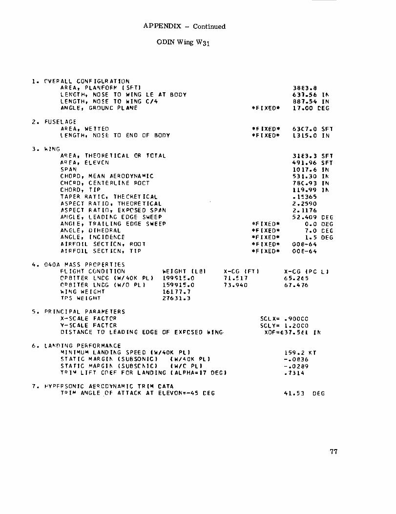
APPENDIX- Continued
ODIN Wing W31
1. _VERALL CONFIGtRATIONAREA, PLANFOFV (SFT)
LENGTH, NOSE TO WING LE AT BODYLENGTH, NOOSE TO WING C/4ANGLE, GROUND PLANE
2. FUSELAGE
AREAt WETTED
LENGTH, NOSE TO END OF BODY
3. k ING
AREAw THEORETICAL CR TOTAL
A_EAt ELEVEN
SPAN
CHORD, MEAN AERODYNAMIC
CHCRDt CEKTERLIKE ROCT
CHOORD _ TIP
TAPER RATIO, THEORETICAL
ASPECT RATIO, THEORETICAL
ASPECT RATIOO, EXPOSED SPiN
AHGLE, LEADIkG EDGE SWEEP
ANGtE, TRAILING EDGE SWEEP
ANGLE, L)IHEDRAL
ANGLE, INC IDEP, CE
AIRFOIL SECTICN, ROOT
AIRFOIL SECTIEN, TIP
4. 040A MASS PROPERTIES
FLIGHT C_NDIT ION
OPBITER LNCG (W/40K PL)
_DBITER LNDG (W/DO PL)
WING WEIGHT
TPS WEIGHT
WEIGHT (LB!
I99¢;1.=.015991_.0
16177.727631,3
5. PRINCIPAL PARAMETERS
X-SCALE FACTOR
Y-SCALE FACTOR
DISTANCE TO LEADING EDGE OF EXPOSED WING-
6. LAt_'DING PE_F(]RMA/_CE
MINIMUN LANDIkG SPEED (WI40K PL)
STATIC MARGI/_ (SUBSONIC) (W/40K PL)
STATIC MARGIf_ (SUBSOkIC) IW/C PLI
ToI_4 LIFT COEF FOR LANDING (ALPHA=|7 DEG|
7. I_YPFRSONIC AERODYNAMIC TRIt4 DATA
T_I_ ANGLE OF ATTACK AT ELEVON=-45 CEG
*FIXED*
38E3,8
63_o56 Ik
887.54 IN
L7.O0 CEG
*FIXED**FIXED*
63C7,0 SFTL315,0 IN
*FIXED*
*FIXED**FIXED*
*FIXED**FIXED*
31E3.3 SFT491.96 SFT
10 17.6 IN53 1,30 I_
78C.93 IN1[9.99 I_
.1_3652°25902.1176
52.409 DEG
0.0 OEG
7.0 DEE1.5 DEG
008-6400E-64
X-CG (FT)
71.51773.940
X-CG IPC L I65,265
67,.476
SCLX= . 900C0
SCLY= L.20CO
XOF=637.5(I II_
159.2 KT
-.0836
-.0289.7314
41.$3 DEG
77

APPENDIX- Continued
ODIN Wing W32
ODIN SU_MARY DATA, 040 A PITCH.TRIM PROBLEM
.90000 1.4000 52.322
I. OVERALL CCNFIGU_ATICN
AREA, PLANFCRP (SFT)
LENGTH, NOSE TO WING LE AT BODY
LEh GT_, NOS_ TD WING C/4
ANGLE, GRCUNO PLANE
CYCLE I
4/27/72
*FIXED*
4245.6627.E6 IN
887.14 IN
17.00 DEG
2. FUSELAGE
AREA, WETTED *FIXED* 6307.0 SFT
LENGTH, NOSE TC END CF BODY *FIXED* 1315.0 IN
3. WING
.......... AREA, -THEORETICal OR TOTAL ....................................... 3531L7 SFT
AREA, ELEVCh 573.96 SFT
SPAN 1153.2 IN
CHORD, MEAN AERODYNAMIC 51B._I IN
CHORD, CENTERLI_E ROCT " 762.00 IN
CHORD, TIP - | 19.99 IN
...........TAPER RATIO, THEORETICAL ......................................... .15746
ASPECT RATIO, TFEORETICAL 2.EIO0
- ASPECT RATIC, E_POSED SPAN " " " 2.4705
ANGLE, LEADING EDGE SWEEP 48.071 DEG
ANGLE, TRAILING EDGE SWEEP " *FIXED* 0.0 DEG" ANGLE, DIHEDRAL " " - *FIXED* ?.0 DEG
............... ANGLE, INCICENCE ................................. *FIXED* ...... 1.5 DEG
AIRFOIL SECTION, ROOT *FIXED* 008-6@
AIRFOIL SECTION, TIP *FIXED* 008-64
4. 040A MASS PROPERTIES
FLIGHT CONDITION WEIGHT (LBI X-CG (FT) X-CG {PC L)
............ ORBITER LNDG (W/40K PLI -2034"II.8 ...... 71.698 ........ 65.430 " "
" " ORBITER LNDG (_18 PL) 163411.8
WING WEIGHT 17845.8
TPS WEIGHT 29460.0
" 5. PRINCIPAL PARAMEIERS - -
............ X-SCALE FACTCR " = .....
• Y-SCALE FACIOR
DISTANCE TO LEACING EDGE OF EXPOSED WING
6. LANDING PERFORMANCE
MINIMU_ LANCING SPEED (W/40K PLI
-STATIC MARGIN (SUBSONIC) IW/40K PL)-
" " STATIC MARGIN (_UBSONICI (W/O PLI
.... TRIM LIFT CCEF FOR LA_DING (ALPHA=IT DEGI
-7. HYPERSONIC AE_CDYNA_IC TRIM DATA
TRIM ANGLE DF AITACK AT ELEVON=-@5 DEG
74.113 67.634
SCEX:--_90000 .......
SCLY: 1.4000
XCF:627.864 IN -
I_4.3 KT
-.081q
-.026I.B164
38.33 DEG
78

APPENDIX- Continued
ODIN Wing W33
7_'ALT.- C--O FAREA, PLANFORM (S_T)
LENGTH, NOSE TO WING LE A_
LENGTH, NOSE TO WING C/4
ANGLE, GRQUNO PLANE *F I XEI)*
3_0-3.4
0_.70 IN
8g0.35 IN
17.00 DEG
_o FUSELAGE
AREA, WETfED ......................... _F_I3(E'I'J_---6307-,O
LENSTH, NOSE IO END OF BODY- .............. _ ...... I_3-[_-1"1_--
"3. wING
A_,,_A_R_A L 2_4 ;_-_Trl "-AREA, ELEVON .......................... 4_/3_. 74 -SF1 _
SP-AN ........ lOS._ o4 IN
CNORD,-_I_F AERODYNAMIC .................. _6&-,_4 IN
CHORD, TIH I06.66 IN
TAPER RATIO, THEORETICAIZ ............... .]5_6_ - -ASPEC| PAYlO, THEOF_ETIC_I_ ................... 2.7417 _
ASPECI-RAfIO, EXPOSED SPAN_ ............................ _,Sh_A -
ANGLE, LE_DING EDGE'_W-EE'P ........................ _6,_2S _£GANGLE, TRAILING EhGE SWEEP- ..................... _F_XEO _ - 0.0 _FG
ANGLE, DIHEDRAL *FIXED _ 7.00EG
aNGLE, INglDENCE ............. _F_XEb _ " I.50FG
AIRFOIL SECTION, R_)CFT .............. _F]XED _ O08-64-AIRFnIL S_CTION_TIP ............. _F]XED _ 008-64
-_C,O_M_iS-TS_I:r_ ....................
FLIGHI CONDITION WEIGHT (L_) X-CG (FT) X-CG (PC LI
ORBITER LNDO (W/40K PL) |_-(}_#-0_-- - _;202 ......... 6_977
_QBITER LNDG (W/O PL) .... l_"gZ_ .......... _;5_- .... 67,i"IS " -
TPS wEIGHT ............. 27G_6 ._ ..............
5. PRINCIPAL PARAMETERS
x-SCALE FACTOR
y-SCALE FACTOR
nISTANCE TO LEADING EDGE OF EXPOSEn WING
SCLY= I.3000
XOF:663.6O& iN- -
6, LANDING PERFOBMANCE
MINIMUM LANDING SPEED (W/_OK PL) 153._ KT
STA-flC--MA-_FG-IN (SUBSONIC) (W/kOK oL) .............. -.0900- "
........ _TATICMARGIN _TLTRSON I C ) ( WiPLT_ ................... --. 0297
7, HYPERSONIC AERODYNAMIC TRIM DATA
TRIM ANGLE OF ATTACK AT ELEVON=-k5 DEG '_5° 66 I)EG
79
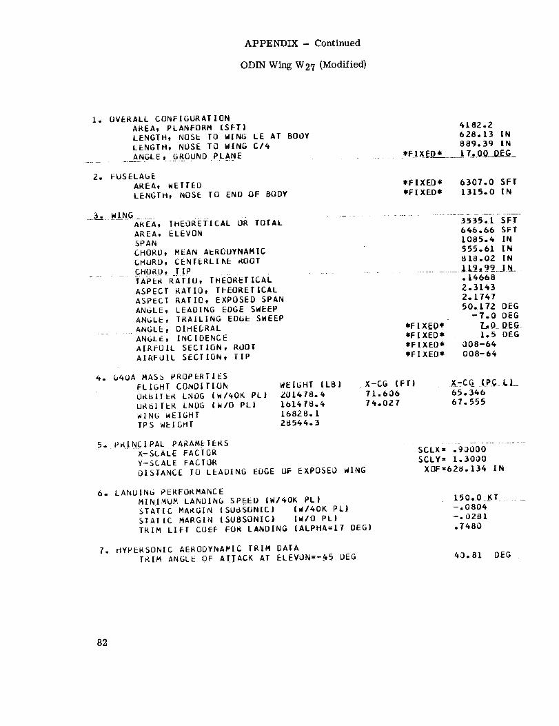
APPENDIX- Continued
ODIN Wing W27 (Modified)
I. OVERALL CONFIGURATION
AREA, PLANFORM ISFT)
LENGTH, NOSE TO WING LE AT BODY
LENGTH, NOSE TD WING C/6
.......... _NGLE t.GR._U ND _PLAN E _ _ *FIXED*
6182.2
628.13 IN889,,39 INi 7. O0 DEG
2. FUSELAGE
AREA, WETTED
LENGTH, NOSE TO END OF BODY
*FIXED* 6307.0 SFT
*FIXED* 1315.0 IN
3° WING
............AREA, THEORETICAL OR TOTAL
AREA, ELEVONSPAN
CHORD, MEAN A_RODYNAMIC
CHURD, CENTERLI_E ROOT
........ CHPaD, _TIP ........
TAPER RATIU, THEORETICAL
ASPECT RATIO, TFEORETICAL
ASPECT RATIO, EXPOSED SPAN
ANGLE, LEADING EDGE SWEEP
ANbLE, TRAILING EDGE SWEEP
ANGLE_ DIHEDRALANGLE, INCIDENCE
AIRFOIL SECTION, ROOT
AIRFOIL SECTION, TIP
6_6.66 SFT1085.4 IN
555.61 IN8£8.02 IN
.14668
2.31_3Z.174750. I72 DEG
-7.0 OEG*FIXEO* 7_,0 DEG*FIXED= l.fi DEG*FIXED* 008-64
*FIXED= 008-6_
4. O4UA MASS PROPERTIES
FLIGHT CONDITION
ORBITER LNOG (WI_OK PLI
UR_ITER LNDG {W/O PL|
WING WEIGHT
TPS WEIGHT
WEIGHT (LB}
Z01678.6
1b16/8.6
i6828. L
28564.3
X-CG (FT| _X=CG ..KP£_..LI__
71.606 65.36b76.027 67.555
.5, PK!NCIPAL PARAMETERSX-SCALE FACICR
Y-SCALE FACTOR
OISTANCE TO LEADING EOGE UF EXPOSED WING
SCLX=: 0606............SCLY= 1.300O
XOF=628.136 IN
6. LANDING PERFORMANCE
MINIMUM LA_DING SPEED IWI40K PLISTATIC MARGIN (SUBSONIC| IW/60K PLI
STAIIC MARGIN (SUBSONIC} (WIO PL|
TRIM LIFT COEF FOg LANDING {ALPHA=IT DEG)
150_0 KT ........
-°0806-.0281
.7680
7. HYPERSONIC AERODYNAMIC TRIM DAIA
TRIM ANGLE OF ATTACK AT ELEVON=-_5 DEG . 63.81 DEG
82

APPENDIX- Concluded
ODIN Wing W33 (Modified)
[. OVERALL CCNFIGURATIONAREA, PLANFORM (SFT| 4069.]LENGTH, NOSE TO WING LE AT BODY b51.70 IN
LENGTH, NOSE TO WING C/4 892.80 IN
ANGLE, GRDUNO pL_A_NE......................................... __FI_X_ED* _[7.0Q - D__E_G
2. FUSELAGE
AREA, WETTED
LENGTH, NOSE TO END OF BODY
*FIXED* 6307.0 SFT
*FIXED* [315.0 IN
3. WING
AREA, THEORETICAL OR TOTAL 3387.[ SFT
AREA, ELEVON 73I.03 SFTSPAN [085.4 IN
CHORD, MEAN AERCDYNAMIC 53b.52 IN
CHORD, CENTERLI_E ROOT 792.09 IN
......... 0,.._TJP ...........................................................To6 6__.!N_.TAPER RATIO, THEOi_ETICAL
ASPECT RATIO, THEORETICAL
ASPECT RATIO, EXPOSED SPAN
ANGLE, LEADING EDGE SWEEP
ANGLE, TRAILING EDGE SWEEP
ANGLE, INCIDENCE
AIRFOIL SECTION, ROOT
AIRFOIL SECTION, TIP
.[34652.4154
2.289666.825 DEG
--il.O DEG
.....*EI_D_ .........J__Q .DEG*FIXED* 1.5 DEG
*FIXED* 008-64*FIXED* 008-64
6. 040A MASS PROPERTIES
FLIGHT CONDITION . _EIGHT .(LB.)..ORBITER t_0G (W/40K PLI 199609.0
ORBITER LNOG (WIO PLI L59609.3
aING wEIGHT [6476.8TPS WEIGHT 2702b.2
TL.LBL 54.95873.523 67.096
_5_ _PR!.N_IPAL PAR AMETERS ................X-SCALE FACTOR
Y-SCALE FACTOR
DISTANCE TO LEADING EDGE OF EXPOSED alNG
sccx -.aO00o ......SCLY= 1.3000
XL)F=651. b96 IN
6. LANDINb PERFORMANCE
MINIMUM LANOING SPEED (W/_OK PL|
.......... STATIC MARGIN (SUBSONIC| - (W/40K PLJ _ "
STATIC MARGIN (SUBSONICJ (W/O PLJ
TRIM LIFT COEF FOR LANDING IALPHA=I7 DEGI
7. HYPERSONIC AERODYNAMIC'TRIM DATAi ,
TRIM A@GLk,..OFA.ITACK AT.F..LEVON=-_5 DEG
[99.9 _T
-.0804
-.OZ80.7742
48.90 DEG
83
REFERENCES
1. Glatt, C. R.; Hague, D. S.; and Watson, D.A.: DIALOG: An Executive Computer
Program for Linking Independent Programs. NASA CR-2296, 1973.
2. Glass, K. J.; and Whitnah, A. M.: Static Aerodynamic Characteristics of the
MSC-040A Space Shuttle Orbiter With Wedge Centerline Vertical and Twin Vertical
Tails at Mach Numbers From 0.6 to 4.96. DMS-DR-1243 (NAS 8-4016), Space
Div., Chrysler Corp., Mar. 1972. (Available as NASA CR-120050.)
3. Anon.: Space Shuttle Snythesis Program (SSSP). Vol. II - Weight/Volume Handbook.
Rep. No. GDC-DBB70-002 (Contract NAS 9-11193), Convair Aerospace Div.,
General Dynamics, Dec. 1970. (Available as NASA CR-114987.)
4. Fox, M. K. ; Barnes, K. H. ; Harrington, L. J. ; Mauzy, E. L. ; et al.: Investigation of
Techniques To Evaluate Design Tradeoffs in Lifting Reentry Vehicles. Vol. I -
Prediction Techniques for Generalized Reentry Vehicle Configurations.
AFFDL-TR-66-77, Vol. I, U.S. Air Force, Oct. 1966.
5. Gentry, Arvel E.; and Smyth, Douglas N.: Hypersonic Arbitrary-Body Aerodynamic
Computer Program (Mark IH Version). Rep. DAC 61552 (Air Force Contract
Nos. F 33615 67 C 1008 and F 33615 67 C 1602), McDonnell Douglas Corp., Apr.
1968.
Vol. I - User's Manual. (Available from DDC as AD 851 811.)
Vol. H - Program Formulation and Listings. (Available from DDC as AD 851 812.)
6. Herriot, John G.: Blockage Corrections for Three-Dimensional-Flow Closed-Throat
Wind Tunnels, With Consideration of the Effect of Compressibility. NACA Rep. 995,
1950. (Supersedes NACA RM A7B28.)
7. Garner, H. C.; Rogers, E. W. E.; Acum, W. E. A.; and Maskell, E. C.: Subsonic
Wind Tunnel Wall Corrections. AGARDograph 109, Oct. 1966.
8. Ellison, James C.: Investigation of the Aerodynamic Characteristics of a Hypersonic
Transport Model at Mach Numbers to 6. NASA TN D-6191, 1971.
9. Stone, Howard W. ; and Arrington, James P.: Aerodynamic Studies of Delta-Wing
Shuttle Orbiters. Pt. II - Hypersonics. Vol. III of Space Shuttle Aerothermo-
dynamics Technology Conference, NASA TM X-2508, 1972, pp. 803-829.
10. Freeman, Delma C., Jr.; and Ellison, James C.: Aerodynamic Studies of Delta-Wing
Shuttle Orbiters. Pt. I -' Low Speed. Vol. HI of Space Shuttle Aerothermodynamics
Technology Conference, NASA TM X-2508, 1972, pp. 785-801.
84 NASA-L_._I_y,1974 L-9099

APPENDIX- Continued
ODIN Wing W33
-]_ OVERALL CONFIOURATION -
AREA, PLANFORM (SET)
LENGTH9 NOSE TO WING LE AT-B_DY
LENGTH, NOSE TO WING C/4
aNGLF, GROUND PLANE
3803.4
_,70 IN
890.35 IN
....... *F[XEI)* 17.00 DEG
2. FUSELAGE
AREA, WETIED ........ _FF]XE-I_- _3(F?_usrFT
LENBTH, NOSE I0 END OF BODY - _FgIXE-D_- Ir3]_--]_-
3. WIN5
AREA, TH__R-I'OI'-AL ................... _FOB_,_T
AREA, ELEVON ..................... 473,74 S-_F'I_SPAN ............ I08_.4 IN -CHORD,--_-AERODYNAMIC ........ 466.34 INCHORD, CENI[RLINE-ITO-C)I_ ............. ....6_5.10 IMCHORD, TIM 106o66 IN
TAPER RATIO, THEOPETICAL .................... .I5_6A "
ASPEC1 RAflO, IHEOI_ETICE ................... _.7417
ASPEC| RA_IO, EXPOSED SPAN-_ ................ _oS80_ "
ANGLE, L__='IZY_F-gWEEg ........ _6,A75 DEG
ANGLE, TRAILING EGGEEflEF__ ................. _rlXEO_ " O.ODFfi-
ANGLF, DIHEDRAL *FIXEO* 7.00FG
ANGLE, INCIDENCE ................ *FIXED* - 1,5 DFG_IRFOIL SECTION, _OOT .... _FIXEO* 008-64_OTC_'EL'TID_i_IP ..... _FIXE0* 008:6a
--_. 04UA MASSPRO]_ERTIE-S _ .......
FLIGHI CONDITION WEIGHT (L_} X-CG (FT) X-CG (PC L)
ORBITER--[NDO (W/4oK-hL)--_q_ _ ?-1._02 6#,977
nQBITERI£ND_(W/O PL} .... 13_g_/70_6 ........ _,54_3 67,i15 "wIN_EIG_ .............. __ .......TPS WEIGHT ........... 270_6.2 .....
5, PRINCIPAL PARAMETERS
X-SCALE FACTOR ............ SCLX= .80000
Y-SCALE E_CTOR SCLY= 1.3000 -
nlSTANCE TO LEADING EDGE OF EXPOSEq WiNG ...............XOE=663.696 IN
6, LANDING PEREOEMANCE
MINIMUM L_NDING SPEED (W/40K PL) 153.8 KT
. -[[ --_<fA-TFC--M-A_-CI_(SU_SONXC) (W/40K oL)--_j _ j..... ".OOO0-OA¥1C-MARG|N -(SUBSONIC) (W/_--PL_ --- _.0297 -
7. HYPERSONIC AERODYNAMIC TPIM DATA
TRIM ANGLE OF ATTACK AT ELEVON=-45 DEG _5.60 OE6
79

APPENDIX- Continued
ODINWing W34
I. OVEFALL CCNFIG_RAIICN
AREA, PLANFORM (SFT)
LENGTFt NOSE TO WING LE AT BOCY
LENGTH, NOSE TO WING C14
ANGLE, GROUNC PtJNE
2. FUSELAGE
AREAL WETTED
LENGTH, NOSE TO END CF BODY
3. WING
AREA, THEORETICAL CR TOTAL
AREA, ELEVENSPAN
CHCRD, HEAN AERODYNAMIC
EHCQDt CENTEPLINE _OOT
CHORD, TIP
TAPER RATICt IHEORET ICAL
_SPECT RATIO, THEORETICAL
ASPECT RAT IDt EXPOSED SPAN
ANGLE, LEACIhG EDGE SWEEP
ANGLE, TRAILING EDGE SWEEP
ANGLE, DIHEDRALANGLE, INCIDENCE
AIRFCIL SECTION, RCOT
AIRFOIL SECTICN, TIP
4, C4OA MASS PROPERIIES
FLIGHT CONDITION
ffRBITFR LNOG (WI4OK PL)
F]RBITER LNCG (W/O PL)
WING WEIGH)
TPS WEIGHT
WEIGHT (LB}195 128.5
15512E.5149 39,624082,,8
5. ORINCIPAL PARA_EIERS
X-SCALE FACTC_
Y-SCALE FACTCR
DISTA_C c_ TC LEADING EDGE EF EXPOSEC kING
6. LANDING PERFCRFA_CE
MININUM LANDING SPEED (W/4OK EL)
STATIC MARGIN (SUBSONIC) {WI_OK PL)
STATIC MARGI_ (SUBSONIC) (W/C PL)
T_IM LIFT COEF FOR LANDING (ALPHA=IT DEG)
7. FYPERSC_NIC AERCDY_!AMIC TRIM CATA
TRIM ANGLE OF ATTACK AT ELEVQh=-45 DEG
*FIXED=
3260.7
7C(.16 IN
8S5.99 IN
17.00 OEG
=FIXED*
*FIXED*63C7.0 SFT
1315.0 IN
*FIXED*
*FIXED**FIXED*
*FIXED*=FIXED*
2341.8 SFT350.75 SFT
94S.80 I__1_.37 IN
61(.76 IN93.32_ IN
.I_131
2._752
Z.495747.782 DEC
0.0 DEC
7.0 DEE1°5 DEG
0CE-64008-64
X-CG (FT)
70,68772._70
X-CG (PC LI64.. 5C766.5(_i
SCLX= .70OCO
SCLY = /.lOOOXOF=706.1E3 IN
171,4 KT-.0940
-.0286.838C
59.1C DEG
80

APPENDIX- Continued
ODIN Wing W35
I. OVERALL CCNFIGLRATION
AREA, PLANFO_._ (SFT)
LE/_GTH, NOSE TO WING LE AT BCCY
LENGTH, NOSE TO WING C14
ANGLE, GROUND PLANE
2. FUSELAGE
APEA, WETTED
LENGTH, NOSE TO END CF BODY
3. WING
APEA, THEORETICAL CR TOTAL
AREA, EL EVON
SPAN
CHORD, MEAN AERODYNAMIC
CHORD, CENTERLIf_E RFCT
CHORD, TIP
TAPER RATIO, ThEC_RETICAL
ASPECT RATIO, THEORETICAL
ASPECT RATIO, EXPOSEC SPAN
ANGLE, LEAOII_G EDGE SWEEP
ANGLE, TRAILIKG EDGE SWEEP
ANGLE, DIHEDRALAKGLEt I NC ICEt_CE
AIRFOIL SECTION, ROOT
AIRFOIL SECTION, TIP
4. 040A _ASS PROPERTIES
FLIGHT CONDITION
CPBITER LNEG (WI40K PLI
r'PBITER LNDG (W/O PLI
WING WEIGHT
TPS WEIGHT
WEIGHT {LBI
19671L,.8
15671_1.8
15812.E
24796.1
5. PRINCIPAL PARAMEIERS
X-SCALE FACTOR
Y-SCALE FACTOR
DISTANCE TO LEADING FOGE OF EXPOSED kING
6. LANDING PERFORt_AI_CEMINIMUM LA/_DIRG SPEEC {WI40K Ft|
STATIC MARGIN (SUBSr)N[C} (WI40K PL}
STATIC MARGIN {SUBSONIC) {WIC PL}
T_I M LIFT COEF FOR LANDING {ALPHA=IT CEG)
7, I_YPERSONIC AERODYNAMIC TRIM CATA
TRI_ ANGLE CF ATTACK AT ELEVOI_=-4_ = DEG
*FIXED*
3401.469_.20 IN
893°63 INI7.00 DEG
*FIXED*
*FIXED*
6307.0 SFT
1315.0 IN
*FIXED**FIXED*
*FIXED**FIXED*
*FIXED*
2475°9 SFT
382.6# SFT
I017.6 IN
413.23 IN
6C7.39 IN
93.324 I_
.1_3652.904_
2.722645.294 DEG
O.O DEG
7.0 DEG1,5 DEG
008-640C8-64
X-CG (FT|
70.74673.021
X-CG {PC L )
64.561
66.637
SCLX= .700CO
SCLY= l.2OCO
XOF=699.1_8 I_
163.4 KT
-.0949-.02E9
.8787
56,6S DEG
81
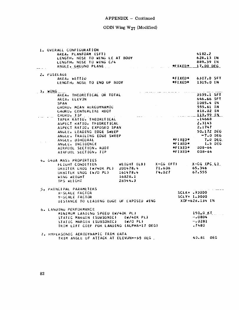
APPENDIX- Continued
ODIN Wing W27 (Modified)
1. OVERALL CONFIGURATIONAREA, PLANFORM (SFT)LENGTH, NOSE TO WING LE AT BODY
LENGTH, NOSE TO WING C14
.......... A_NGLE t ._.G._R(JUNO _PLANE _. *F IXEO*
4182.2628.13 IN889.39 IN
17.00 DEG
2. FUSELAGE
AREA, _ETTED
LENGTH, NOSE TO END OF BODY
*FIXED* 6307.0 SFT
*FIXED* 1315.0 IN
3. W.I_NG_.....AREA, THEORETICAL OR TOTAL
AREA, ELEVON
SPAN
CHORU, MEAN A_RODYNAMIC
CHORD, CENTERLI_E ROOT
..... ... CHPRD_ SiPTAPER RATIU-, THEORETIcAL
ASPECT RATIO, TFEORETICAL
ASPECT RATIO, EXPOSED SPAN
ANGLE, LEADING EDGE SWEEP
AN_LE, TRAILING EDGE SWEEP
ANGLE, DIHEDRALANGLE, INCIDENCEAIRFOIL SECTION, ROOTAIRFJIL SECTION, TIP
..........................646.66 SFT1085.4 IN
555.61 IN8[8.02 IN
.............. l._]__.9__J_[_..14668
2.31432.1747
50.172 DEG-7.0 DEG
*FIXEO* 7,,_ DE_*FIXED* 1.5 DEG
*FIXED* 008-64
*FIXED* 008-64
4. O4OA MASS PROPERTIES
FLIGHT CONDITION
ORBITER LNOG (WI4OK PL)
ORBITER LNDG (WIO PL)
WING _EIGHT
TPS WEIGHT
WEIGHT (LBI
;_01478.
16828. I
28544.3
X-CG (FT) . X_:C.G_ IP__LI_
71.606 65.346
7_.0Z7 67.555
5. PR!NCIPAL PARAMETERSX-SCALE FACIOR
Y-SCALE FACTOR
DISTANCE TO LEADING EDGE UF EXPOSED WING
SCLX= ,-boO-ob..........SCLY = 1.3000
XOF=628. 134 IN
6. LANDING PERFORMANCEMINIMUM LANDING SPEED (W/40K PL|
STATIC MARGIN (SUBSONIC| (W/4OK PL)
STATIC MARGIN (SUBSONIC) {WIO PL|
TRIM LIFT COEF FOR LANDING (ALPHA=I7 DEG)
150_0 KT .....
-.0804
-.0281.7_8D
7. HYPERSONIC AEROOYNAPIC TRIM DATA
TRIM ANGLE OF ATTACK AT ELEVON=-._ DEG . 40.81 OEG
82

APPENDIX- Concluded
ODIN Wing W33 (Modified)
I. OVERALL CCNFIGURATIONAREA, PLANFORM (SFI'|
LENGTH, NOSE TO WING LE AT BODY
LENGTH, NOSE TO WING C16
ANGLE, GROUND PLANE
4069.3651.70 IN
892.80 IN
*E i_X_ED___ __=i.7.;00= D_E_G
2. FUSELAGE
AREA, WETTED
LENGTH, NOSE TO END OF BODY*FIXED* 6307.0 SFT
*FIXED* 1.3t5.0 IN
3. WING
AREA, THEORE-i[CAL-OR-TOrAL ............................................. 3387_-ISFT--
AREA, ELEVON 731.03 SFT
SPAN 1085.4 IN
CHORD, MEAN AEREUYNAMIC 536.52 IN
CHORD, CENTERLI_E ROOT 192.09 INCHORD TIP................,............................................ E0_._66LNTAPER RATIO, THEOI_ETICAL .13665ASPECT RATIO, THEORETICAL
ASPECT RATIO, EXPOSED SPAN
ANGLE, LEAOING EDGE SWEEP
ANGLE, TRAILING EDGE SWEEP
ANGLE, DIHEDRAL
ANGLE, INCIDENCE
AIRFUIL SECTION, ROOT
AIRFOIL SECIION, TIP
2.41562.2896
@6.B25 DEG
--11.0 DEG
*FIXED* t.5 DEG
*FIXED* OOB-64
*FIXED* 008-64
4. O40A MASS PROPERTIES
ORBITER L;WDG (W/4OK PLI 199609.0 11.[8[URBIIER LNOG (W/O PL) 159609.3 73.523
aING wEIGHT 16416.8
IPS WEIGHT 27026°2
_=X=--;G._!_P_C_LJ_6_..95867. 096
_5_ PR!NCIPA L PARAMETERSX-SCALE FACIOR
Y-SCALE FACTOR
DISTANCE TO LEADING EDGE OF EXPOSEO +[NG
scLx= Taoooo ....SCLY= I. 3000
XOF=651 .b96 IN
b. LANDINb PERFORMANCE
MINIMUM LANOING SPEED (W/40K PLI
STATIC MARGIN (SUBSONIC) IW/6OK PL)
STATIC MARGIN (SUBSONIC) IW/O PLI
TRIM LIFT COEF FOR LANDING (ALPHA=IT DEG)
HYPERSONIC AERODYNAMICIRIM DATA7.
TRIM A@GL_-OF A.ITACK A/_F..LEVON=-_5 DEG
-.0804
-.0280.1742
48,90 DEG
83

REFERENCES
1. Glatt, C. R.; Hague, D. S., and Watson, D.A.: DIALOG: An Executive Computer
Program for Linking Independent Programs. NASA CR-2296, 1973.
2. Glass, K. J.; and Whitnah, A. M.: Static Aerodynamic Characteristics of the
MSC-040A Space Shuttle Orbiter With Wedge Centerline Vertical and Twin Vertical
Tails at Mach Numbers From 0.6 to 4.96. DMS-DR-1243 (NAS 8-4016), Space
Div., Chrysler Corp., Mar. 1972. (Available as NASA CR-120050.)
3. Anon.: Space Shuttle Snythesis Program (SSSP). Vol. II - Weight/Volume Handbook.
Rep. No. GDC-DBB70-002 (Contract NAS 9-11193), Convair Aerospace Div.,
General Dynamics, Dec. 1970. (Available as NASA CR-114987.)
4. Fox, M. K.; Barnes, K. H.; Harrington, L. J.; Mauzy, E. L.; et al.: Investigation of
Techniques To Evaluate Design Tradeoffs in Lifting Reentry Vehicles. Vol. I -
Prediction Techniques for Generalized Reentry Vehicle Configurations.
AFFDL-TR-66-77, Vol. I, U.S. Air Force, Oct. 1966.
5. Gentry, Arvel E.; and Smyth, Douglas N.: Hypersonic Arbitrary-Body Aerodynamic
Computer Program (Mark HI Version). Rep. DAC 61552 (Air Force Contract
Nos. F 33615 67 C 1008 and F 33615 67 C 1602), McDonnell Douglas Corp., Apr.
1968.
Vol. I - User's Manual. (Available from DDC as AD 851 811.)
Vol. II - Program Formulation and Listings. (Available from DDC as AD 851 812.)
6. Herriot, John G.: Blockage Corrections for Three-Dimensional-Flow Closed-Throat
Wind Tunnels, With Consideration of the Effect of Compressibility. NACA Rep. 995,
1950. (Supersedes NACA RM A7B28.)
7. Garner, H. C.; Rogers, E. W. E.; Acum, W. E. A.; and Maskell, E. C.: Subsonic
Wind Tunnel Wall Corrections. AGARDograph 109, Oct. 1966.
8. Ellison, James C.: Investigation of the Aerodynamic Characteristics of a Hypersonic
Transport Model at Mach Numbers to 6. NASA TN D-6191, 1971.
9. Stone, Howard W.; and Arrington, James P.: Aerodynamic Studies of Delta-Wing
Shuttle Orbiters. 1_. II - Hypersonics. Vol. III of Space Shuttle Aerothermo-
dynamics Technology Conference, NASA TM X-2508, 1972, pp. 803-829.
10. Freeman, Delma C., Jr.; and Ellison, James C.: Aerodynamic Studies of Delta-Wing
Shuttle Orbiters. Pt. I -" Low Speed. Vol. HI of Space Shuttle Aerothermodynamics
Technology Conference, NASA TM X-2508, 1972, pp. 785-801.
84 NASA-C,,ng1_y,,974L-9099