x moment load my moment load mz up to 5500 nm - comoso …€¦ · · 2013-10-30moment load mx up...
TRANSCRIPT

30 w w w . s c h u n k . c o m
SWSTool Changing · Quick-change System
Sizes005 .. 602
Handling weightup to 1000 kg
Moment load Mxup to 13000 Nm
Moment load Myup to 13000 Nm
Moment load Mzup to 5500 Nm
Application example
Joining tool for attaching small to medium-sized workpieces. The tool can be usedin both clean and dirty environments.The quick-change system means that it can be used alternately with other tools on the robot flange.
DPZ-plus 100 3-Finger Centric Gripper
FUS-213C Insertion Unit
SWS-041 Quick-change System
02-Wechseln_RZ_0708_EN.qxd:02-Wechseln GB.qxd 01.10.2008 9:56 Uhr Seite 30
www.comoso.com

31w w w . s c h u n k . c o m
SWSTool Changing · Quick-change System
Complete series with 15 sizesfor an optimum selection of sizes and a wide range of applicationsPatented self-retaining locking systemfor a safe connection between the quick-change head and thequick-change adapterDrive incorporated into the housingfor compact dimensions and fewer interfering contoursAll functional components made from hardened steelfor a greater change system load bearing capacityWide range of cable connectors for universal energy transmission options Integrated air feed-throughfor safe energy supply to the handling modules and toolsTransmission options for other mediawith optional self-sealing couplingsAdapter coding possible via plug connectionStorage racks to fit all sizes available as an accessory for reliable positioning of your toolsISO flange for easy attachment to most types of robots without additionaladapter plates
Pneumatic tool changing systemwith patented locking system
Quick-change System
Area of applicationCan be used wherever short changeover times between a handlingdevice and a tool (gripper, electrode holder) are required
Your advantages and benefits
General information on the seriesWorking principlePiston-activated locking bearingsMaterialHousing made from high-strength, hard-coated aluminum, functional componentsmade from hardened steelActuationPneumatic, with filtered compressed air (10 µm): dry or lubricatedOperating pressure rangeFrom 4.5 bar to 6 bar MaintenancePrelubricated – relubrication recommended after 2 million cycles
Ambient temperatureFrom 5 °C to 60 °CEnergy transmissionVariable via attachment modules, depending on the typeMonitoring for the locking mechanismvia inductive proximity switches, depending on the sizeSelf-lockingMechanical when lockingWarranty24 months
02-Wechseln_RZ_0708_EN.qxd:02-Wechseln GB.qxd 25.09.2008 10:52 Uhr Seite 31
www.comoso.com

32 w w w . s c h u n k . c o m
SWSTool Changing · Quick-change System
Sensor monitoring for the lockingmechanismincorporated into the housing in the SWS-110, optional with other sizes
Housingweight-reduced through the use of a high-strength aluminum alloy
Drivepneumatic and powerful with extremely easyhandling
Locking mechanismtrouble-free locking and unlocking, self-lock-ing in locked position
Pneumatics feed-throughincorporation into the housing therefore nointerfering contours, also suitable for vacuums
Automatic changing of the robot tool (e.g. gripper, vacuum lifting devices, pneumaticallyor electrically driven tools, electrode holders etc.) increases the flexibility of your robot.The quick-change system (SWS) consists of a quick-change head (SWK) anda quick-change adapter (SWA). The SWK, mounted onto the robot, couples up theSWA mounted onto your tool. A pneumatically driven locking piston, with its patented design, ensures that the connection is secure. After coupling, pneumaticand electric feed-throughs automatically supply your robot tool.
Function description
Sectional diagram
02-Wechseln_RZ_0708_EN.qxd:02-Wechseln GB.qxd 25.09.2008 10:57 Uhr Seite 32
www.comoso.com

33w w w . s c h u n k . c o m
SWSTool Changing · Quick-change System
Use in extreme ambient conditionsPlease note that use in extreme ambient conditions (e.g. in the coolant zone, inthe presence of abrasive dust) can significantly reduce the life span of these unitsand we cannot accept any liability for this reduction. However, in many cases wehave a solution at hand. Please ask for details.
General information on the series
Accessories from SCHUNK –the suitable supplement formaximum functionality, reli-ability and performance ofall automation modules.
SIP sensor interface plate Storage racks
Accessories
� For the exact size of the accessories, the availability for this size and the designation and ID, please refer to the additional views at the end of the size in question.
Cable connectors
Electronic modules
02-Wechseln_RZ_0708_EN.qxd:02-Wechseln GB.qxd 25.09.2008 10:57 Uhr Seite 33
www.comoso.com

34 w w w . s c h u n k . c o m
SWSTool Changing · Quick-change System
Detailed function description
SWK - SWA before locking
Piston
When the piston is actuated the locking balls arepushed under the hardened steel ring and theadapter is pulled onto the head.
Locking piston
No-Touch-Locking™
(no robot pressure force needed when locking)
Hardened locking ball on the first locking bevel
Hardened steel insert
Locking ball on the second locking piston bevel
First locking bevelSWK - SWA when locked
Detailed view
Detailed view
In the event of a drop in air pressure, the locking pis-ton is held by the cylindrical part of the locking piston. The piston seal friction prevents the piston from mov-ing due to its own weight or because of vibrations. The head and the adapter can only be separated bypneumatic actuation of the piston.
Locking ball on the cylindrical part of the locking piston. Compressed air is needed to detach it.
SWK - SWA in self-locking position Detailed view
02-Wechseln_RZ_0708_EN.qxd:02-Wechseln GB.qxd 25.09.2008 10:57 Uhr Seite 34
www.comoso.com

35w w w . s c h u n k . c o m
SWSTool Changing · Quick-change System
Selecting the quick-change system
SWS sizes at a glance
1. Size selectiona. Simple size determination
If the change system is subject to very low forces and moments you can select the quick-change head on the basis of the maximum payload. Choose a quick-change system which has a maximum payload larger than the useful load of your robot. Choose the accurate method if the change system is subject to higher moments.
b. The accurate methodSelecting the correct quick-change system depends on the moment load which the system is subject to. Proceed as follows to calculate the maximum moments.· Determine the center of gravity and the weight (m in Newtons) of your heaviest tool (gripper, adapter plate and tool)· Determine the distance (D in meters) from the center of gravity to the underside of the quick-change adapter (SWA)· Calculate the static moment (m x D)· Select a quick-change system with a permissible moment that is equal to or greater than the moment you have calculated
Robot movements can also have an effect on the change system. Dynamic moments can come into effect which are 2 – 3 times greater than the static momentsyou have calculated. The SWS quick-change systems are designed for handling dynamic moments which can be up to three times greater than the static moments.
2. Pneumatics and electricsDetermine the number and sizes of the pneumatic and electric feed-throughs.
3. Temperature and chemicalsNitrile seals on the quick-change units ensure optimum air feed-through. Buna N O-rings seal the piston chamber very effectively. Both materials are resistant to many chemicals and are suited to temperatures between 5 °C and 60 °C.
Designation SWS-005 SWS-011 SWS-020 SWS-021 SWS-040 SWS-041Recommended handling weight [kg] 8 16 25 25 50 50Locking force at 5.5 bar [N] 690 1068 2314 2314 4540 4540Static moment Mx and My [Nm] 12.5 25 56.5 56.5 157 157Static moment Mz [Nm] 17 34 78 78 216 216Pneumatic feed-through 6x M5 6x M5 12x M5 8x G 1/8” 8x G 1/8” 6x G 3/8”Air connections, locked and unlocked M5 M5 M5 M5 G 1/8” G 1/8”
Designation SWS-060 SWS-071 SWS-110 SWS-150 SWS-300Recommended handling weight [kg] 75 79 150 200 455Locking force at 5.5 bar [N] 7387 8075 12149 16109 35333Static moment Mx and My [Nm] 197 395 784 1356 3870Static moment Mz [Nm] 294 395 784 1130 2825Pneumatic feed-through 8x G 1/8” 8x G 1/4” 8x G 3/8” 10x G 3/8” 10x G 3/8”Air connections, locked and unlocked G 1/8” G 1/8” G 1/8” G 1/8” G 1/4”
02-Wechseln_RZ_0708_EN.qxd:02-Wechseln GB.qxd 25.09.2008 10:57 Uhr Seite 35
www.comoso.com

w w w . s c h u n k . c o m36
Ejector function on the SWKPrevents the head and the adapter from stickingtogether after unlocking.A common problem when working with light tools.High degree of repeat accuracyNo-Touch-Locking™Locking without touching. Ensures that the SWS issecurely locked even when the SWK and SWA do nottouch. A maximum distance of 3 mm is possible.Patented, self-retaining locking systemAir feed-through with specially developedrubber seals
SWS-005Tool Changing · Quick-change System · Light Load
Technical dataDesignation SWS-005 Maximum payload [kg] 8 A larger payload is possible with smaller momentsStatic moment load Mxy [Nm] 12.5Static moment load Mz [Nm] 17Dynamic moment load Mxy [Nm] 37.5Dynamic moment load Mz [Nm] 51Locking force (at 6 bar) [N] 710 In the event of higher tensile forces the system “falls” into the self-locking positionRepeat accuracy [mm] 0.01 Tested at 1 million cyclesWeight [kg] 0.37 0.27 kg head; 0.1 kg adapterMin./max. distance on locking [mm] 1.5 / 3.0 No-Touch-Locking™ technology allows the parts to be coupled
without the head and the adapter touchingPneumatic energy transmission 6x pneumatic M5 Max. 7 barMaximum permissible XY offset [mm] ± 1 Maximum permissible XY offset when lockingMaximum permissible angular offset [°] ± 2 Maximum permissible angular offset around the Z axis when locking
Information on moment loadSelecting the correct quick-change system depends on the moment load which the system is subject to. Proceed as follows to calculate the maximum moments.· Determine the center of gravity and the weight (m in Newtons) of your heaviest tool (gripper, adapter plate and tool)· Determine the distance (D in meters) from the center of gravity to the underside of the quick-change adapter (SWA)· Calculate the static moment (m x D)· Select a quick-change system with a permissible moment that is equal to or greater than the moment you have calculated
Robot movements can also have an effect on the change system. Dynamic moments can come into effect which are 2 – 3 times greater than the static moments you havecalculated. The SWS quick-change systems are designed for handling dynamic moments which can be up to three times greater than the static moments.
Moment load Product description
� The dynamic moment load can be up to three timeslarger than the static moment load. Tests haveshown that the system will only begin to fail in theevent of 12-fold static moment.
Mx max. 12.5 NmMy max. 12.5 NmMz max. 17.0 Nm
02-Wechseln_RZ_0708_EN.qxd:02-Wechseln GB.qxd 26.09.2008 9:30 Uhr Seite 36
www.comoso.com
37w w w . s c h u n k . c o m
SWS-005Tool Changing · Quick-change System · Light Load
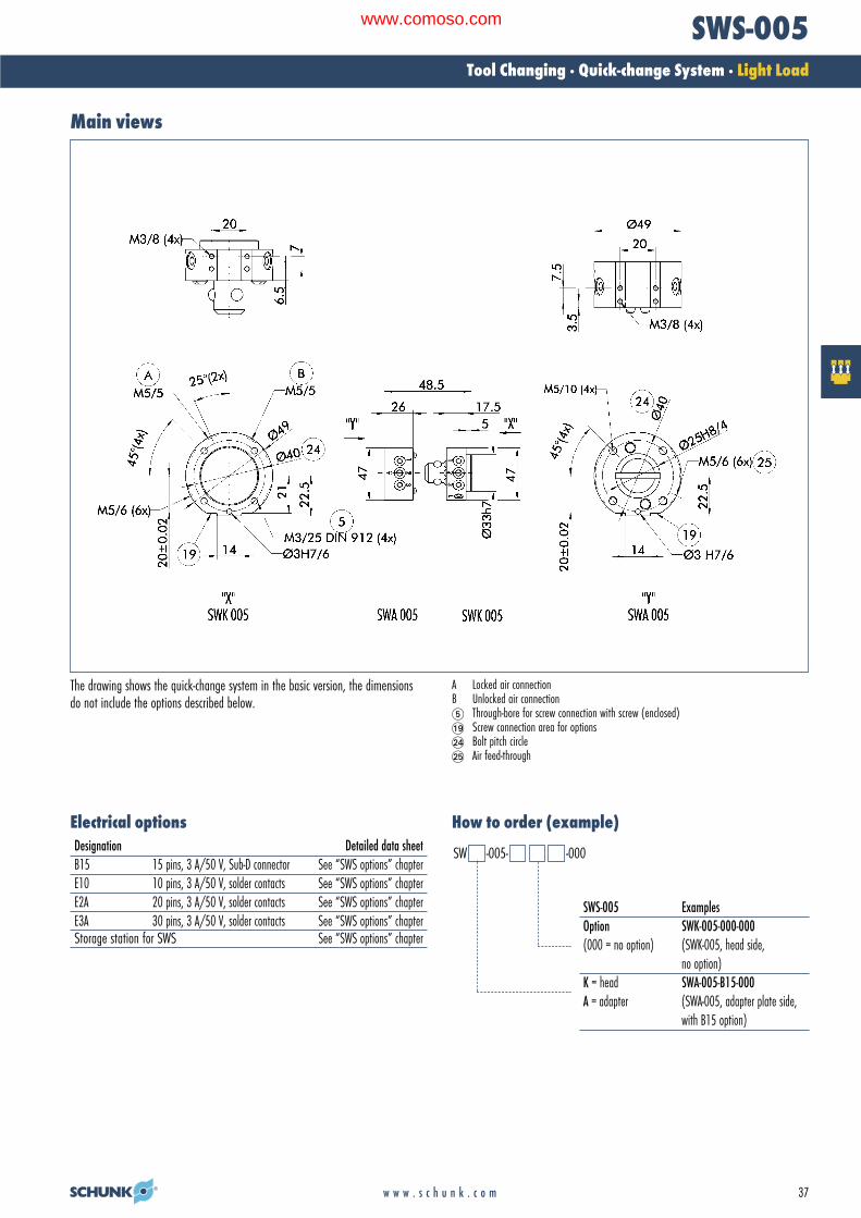
Main views
The drawing shows the quick-change system in the basic version, the dimensionsdo not include the options described below.
A Locked air connectionB Unlocked air connection� Through-bore for screw connection with screw (enclosed)�� Screw connection area for options�� Bolt pitch circle�� Air feed-through
Designation Detailed data sheetB15 15 pins, 3 A/50 V, Sub-D connector See “SWS options” chapterE10 10 pins, 3 A/50 V, solder contacts See “SWS options” chapterE2A 20 pins, 3 A/50 V, solder contacts See “SWS options” chapterE3A 30 pins, 3 A/50 V, solder contacts See “SWS options” chapterStorage station for SWS See “SWS options” chapter
SWS-005 ExamplesOption SWK-005-000-000(000 = no option) (SWK-005, head side,
no option)K = head SWA-005-B15-000A = adapter (SWA-005, adapter plate side,
with B15 option)
Electrical options How to order (example)
SW -005- -000
02-Wechseln_RZ_0708_EN.qxd:02-Wechseln GB.qxd 25.09.2008 10:57 Uhr Seite 37
www.comoso.com

38 w w w . s c h u n k . c o m
SWS-005Tool Changing · Quick-change System · Light Load
Sub-D connector B15Typical set-up on the robot
� Adapter plate on ISO flange Quick-change head SWK Quick-change adapter SWA� Option 1: Electric modules (e.g. B15)� Cable connector for option 1� Option 2
Option: Sub-D connector with 15 spring-loaded, gold-coated pins (3 Amp/50 VAC per pin)
Designation ID Fits Description B15 head 9937326 SWK 15 pin, 3 Amp/50 VAC E option with high-density
Sub-D connectorB15 adapter 9937327 SWA 15 pin, 3 Amp/50 VAC E option with high-density
Sub-D connector
Design information for adapter plateCable connectors
Cable connector for the connection between the B15 module and the cable
StraightCable connectors for ID DesignationB15 head 0301264 KAS-A15-KB15 adapter 0301265 KAS-A15-A
Tool-side connection
Adapter design recommendation. An adapter is required to seal the piston chamber.
02-Wechseln_RZ_0708_EN.qxd:02-Wechseln GB.qxd 25.09.2008 10:57 Uhr Seite 38
www.comoso.com

39w w w . s c h u n k . c o m
SWS-005Tool Changing · Quick-change System · Light Load
Standard adapter plates for ISO flanges
� Robot-side connection � Tool-side connection
Adapter plate A31.5For mounting the SWK-005 directly to a flange in accordance with ISO 9409-1-31.5-4-M5
Designation IDA-SWK-005-ISO-A-31.5 0302218
� Robot-side connection � Tool-side connection
Adapter plate A40For mounting the SWK-005 directly to a flange in accordance with ISO 9409-1-40-M6
Designation IDA-SWK-005-ISO-A-40 0302219
Modular quick-change rack SWM-S
� Robot-side connection � Tool-side connection
Adapter plate A50For mounting the SWK-005 directly to a flange in accordance with ISO 9409-1-50-4-M6
Designation IDA-SWK-005-ISO-A-50 0302220
The modular “small” quick-change rack has been designed for the SWS-005 size.The system’s modular structure enables you to assemble your rack on an individualbasis. Depending on the number of tools, the storage position and the tool sizeallows you to create a rack tailor-made to your application. The option of utilizingunused air feed-throughs for attaching the workpiece bolts is a unique feature.
02-Wechseln_RZ_0708_EN.qxd:02-Wechseln GB.qxd 29.09.2008 12:04 Uhr Seite 39
www.comoso.com
40 w w w . s c h u n k . c o m
SWS-011Tool Changing · Quick-change System · Light Load
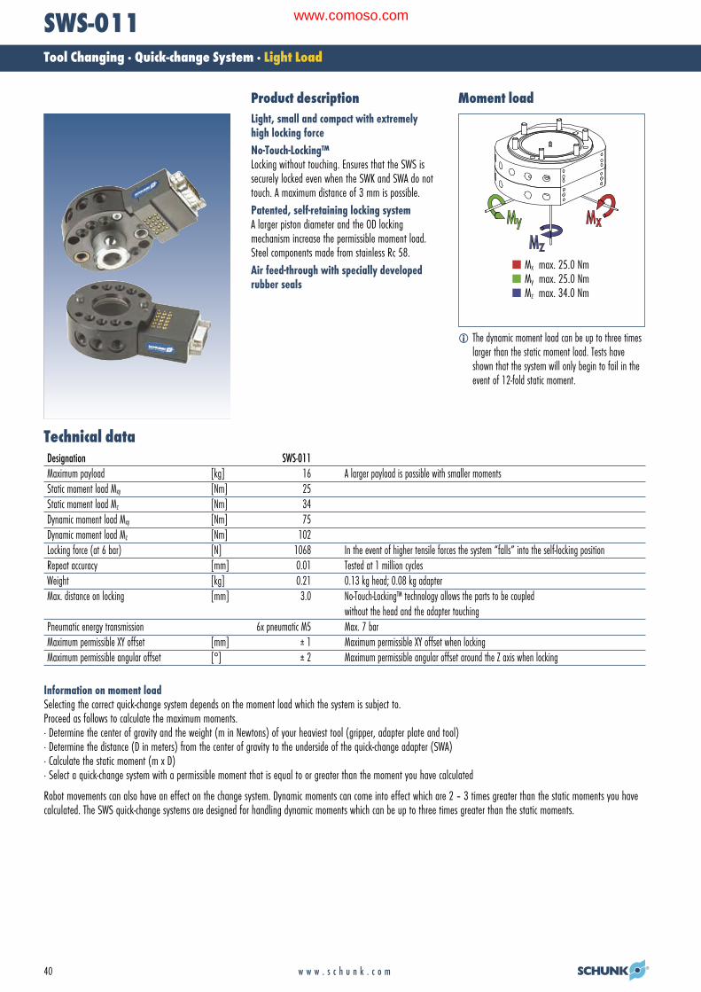
Light, small and compact with extremelyhigh locking forceNo-Touch-Locking™ Locking without touching. Ensures that the SWS issecurely locked even when the SWK and SWA do nottouch. A maximum distance of 3 mm is possible.Patented, self-retaining locking systemA larger piston diameter and the OD locking mechanism increase the permissible moment load.Steel components made from stainless Rc 58.Air feed-through with specially developedrubber seals
Technical dataDesignation SWS-011 Maximum payload [kg] 16 A larger payload is possible with smaller momentsStatic moment load Mxy [Nm] 25Static moment load Mz [Nm] 34Dynamic moment load Mxy [Nm] 75Dynamic moment load Mz [Nm] 102Locking force (at 6 bar) [N] 1068 In the event of higher tensile forces the system “falls” into the self-locking positionRepeat accuracy [mm] 0.01 Tested at 1 million cyclesWeight [kg] 0.21 0.13 kg head; 0.08 kg adapterMax. distance on locking [mm] 3.0 No-Touch-Locking™ technology allows the parts to be coupled
without the head and the adapter touchingPneumatic energy transmission 6x pneumatic M5 Max. 7 barMaximum permissible XY offset [mm] ± 1 Maximum permissible XY offset when lockingMaximum permissible angular offset [°] ± 2 Maximum permissible angular offset around the Z axis when locking
Information on moment loadSelecting the correct quick-change system depends on the moment load which the system is subject to. Proceed as follows to calculate the maximum moments.· Determine the center of gravity and the weight (m in Newtons) of your heaviest tool (gripper, adapter plate and tool)· Determine the distance (D in meters) from the center of gravity to the underside of the quick-change adapter (SWA)· Calculate the static moment (m x D)· Select a quick-change system with a permissible moment that is equal to or greater than the moment you have calculated
Robot movements can also have an effect on the change system. Dynamic moments can come into effect which are 2 – 3 times greater than the static moments you havecalculated. The SWS quick-change systems are designed for handling dynamic moments which can be up to three times greater than the static moments.
Moment load Product description
� The dynamic moment load can be up to three timeslarger than the static moment load. Tests haveshown that the system will only begin to fail in theevent of 12-fold static moment.
Mx max. 25.0 NmMy max. 25.0 NmMz max. 34.0 Nm
02-Wechseln_RZ_0708_EN.qxd:02-Wechseln GB.qxd 26.09.2008 9:30 Uhr Seite 40
www.comoso.com
41w w w . s c h u n k . c o m
SWS-011Tool Changing · Quick-change System · Light Load
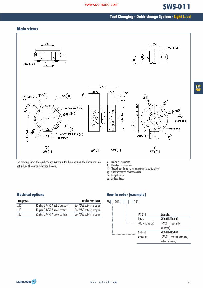
Main views
The drawing shows the quick-change system in the basic version, the dimensions donot include the options described below.
A Locked air connectionB Unlocked air connection� Through-bore for screw connection with screw (enclosed)�� Screw connection area for options�� Bolt pitch circle�� Air feed-through
Designation Detailed data sheetA15 15 pins, 3 A/50 V, Sub-D connector See “SWS options” chapterE10 10 pins, 3 A/50 V, solder contacts See “SWS options” chapterE20 20 pins, 3 A/50 V, solder contacts See “SWS options” chapter SWS-011 Examples
Option SWK-011-000-000(000 = no option) (SWK-011, head side,
no option)K = head SWA-011-A15-000A = adapter (SWA-011, adapter plate side,
with A15 option)
Electrical options How to order (example)
SW -011- -000
02-Wechseln_RZ_0708_EN.qxd:02-Wechseln GB.qxd 25.09.2008 10:57 Uhr Seite 41
www.comoso.com

42 w w w . s c h u n k . c o m
SWS-011Tool Changing · Quick-change System · Light Load
Sub-D connector A15Typical set-up on the robot
� Adapter plate on ISO flange Quick-change head SWK Quick-change adapter SWA� Option 1: Electric modules (e.g. A15)� Cable connector for option 1� Option 2
Option: Sub-D connector with 15 spring-loaded, gold-coated pins (3 Amp/50 VAC per pin)
Designation ID Fits Description A15 head 9936357 SWK 15 pin, 3 Amp/50 VAC E option with Sub-D
connectorA15 adapter 9936356 SWA 15 pin, 3 Amp/50 VAC E option with Sub-D
connector
Design information for adapter plate
Tool-side connection
Adapter design recommendation. An adapter is required to seal the piston chamber.
Cable connectors
Cable connector for the connection between the B15 module and the cable
StraightCable connectors for ID DesignationB15 head 0301264 KAS-A15-KB15 adapter 0301265 KAS-A15-A
02-Wechseln_RZ_0708_EN.qxd:02-Wechseln GB.qxd 25.09.2008 10:57 Uhr Seite 42
www.comoso.com

43w w w . s c h u n k . c o m
SWS-011Tool Changing · Quick-change System · Light Load
Standard adapter plates for ISO flanges
� Robot-side connection � Tool-side connection
Adapter plate A31.5For mounting the SWK-011 directly to a flange in accordance with ISO 9409-1-31.5-4-M5
Designation IDA-SWK-011-ISO-A-31.5 0302221
� Robot-side connection � Tool-side connection
Adapter plate A40For mounting the SWK-011 directly to a flange in accordance with ISO 9409-1-40-M6
Designation IDA-SWK-011-ISO-A-40 0302222
Modular quick-change rack SWM-S
� Robot-side connection � Tool-side connection
Adapter plate A50For mounting the SWK-011 directly to a flange in accordance with ISO 9409-1-50-4-M6
Designation IDA-SWK-011-ISO-A-50 0302223
The modular “small” quick-change rack has been designed for the SWS-011 size.The system’s modular structure enables you to assemble your rack on an individualbasis. Depending on the number of tools, the storage position and the tool sizeallows you to create a rack tailor-made to your application. The option of utilizingunused air feed-throughs for attaching the workpiece bolts is a unique feature.
02-Wechseln_RZ_0708_EN.qxd:02-Wechseln GB.qxd 29.09.2008 12:04 Uhr Seite 43
www.comoso.com

44 w w w . s c h u n k . c o m
SWS-020Tool Changing · Quick-change System · Light Load
12 size M5 air feed-throughs incorporatedinto the housingNo-Touch-Locking™ Locking without touching. Ensures that the SWS issecurely locked even when the SWK and SWA do nottouch.A maximum distance of 3 mm is possible.Patented, self-retaining locking systemA larger piston diameter and the OD locking mechanism increase the permissible moment load.Steel components made from stainless Rc 58.Air feed-through with specially developedrubber seals
Technical dataDesignation SWS-020 Maximum payload [kg] 25 A larger payload is possible with smaller momentsStatic moment load Mxy [Nm] 56.5Static moment load Mz [Nm] 78Dynamic moment load Mxy [Nm] 169.5Dynamic moment load Mz [Nm] 234Locking force (at 6 bar) [N] 2314 In the event of higher tensile forces the system “falls” into the self-locking positionRepeat accuracy [mm] 0.015 Tested at 1 million cyclesWeight [kg] 0.8 0.5 kg head; 0.3 kg adapterMax. distance on locking [mm] 3.0 No-Touch-Locking™ technology allows the parts to be coupled
without the head and the adapter touchingPneumatic energy transmission 12x pneumatic M5 Max. 7 barMaximum permissible XY offset [mm] ± 1 Maximum permissible XY offset when lockingMaximum permissible angular offset [°] ± 2 Maximum permissible angular offset around the Z axis when locking
Information on moment loadSelecting the correct quick-change system depends on the moment load which the system is subject to. Proceed as follows to calculate the maximum moments.· Determine the center of gravity and the weight (m in Newtons) of your heaviest tool (gripper, adapter plate and tool)· Determine the distance (D in meters) from the center of gravity to the underside of the quick-change adapter (SWA)· Calculate the static moment (m x D)· Select a quick-change system with a permissible moment that is equal to or greater than the moment you have calculated
Robot movements can also have an effect on the change system. Dynamic moments can come into effect which are 2 – 3 times greater than the static moments you havecalculated. The SWS quick-change systems are designed for handling dynamic moments which can be up to three times greater than the static moments.
Moment load Product description
� The dynamic moment load can be up to three timeslarger than the static moment load. Tests haveshown that the system will only begin to fail in theevent of 12-fold static moment.
Mx max. 56.5 NmMy max. 56.5 NmMz max. 78.0 Nm
02-Wechseln_RZ_0708_EN.qxd:02-Wechseln GB.qxd 26.09.2008 9:30 Uhr Seite 44
www.comoso.com

45w w w . s c h u n k . c o m
SWS-020Tool Changing · Quick-change System · Light Load
Main views
The drawing shows the quick-change system in the basic version, the dimensions donot include the options described below.
A Locked air connectionB Unlocked air connection� Through-bore for screw connection with screw (enclosed)�� Screw connection area for options�� Bolt pitch circle�� Air feed-through
Designation Detailed data sheetK19 19 pins, 3 A/50 V, MS connector See “SWS options” chapterK26 26 pins, 3 A/50 V, MS connector See “SWS options” chapterKM14 14-pin, (12x5 A/250 VAC* and
2x13 A/250 VAC*) See “SWS options” chapter
* 250 VAC grounding done by customer
Electrical options
SWS-020 ExamplesOption SWK-020-000-000(000 = no option) (SWK-020, head side,
no option)K = head SWA-020-K19-000A = adapter (SWA-020, adapter plate side,
with K19 option)
How to order (example)SW -020- -000
02-Wechseln_RZ_0708_EN.qxd:02-Wechseln GB.qxd 25.09.2008 10:58 Uhr Seite 45
www.comoso.com

46 w w w . s c h u n k . c o m
SWS-020Tool Changing · Quick-change System · Light Load
Quick-change connector K19Typical set-up on the robot
� Adapter plate on ISO flange Quick-change head SWK Quick-change adapter SWA� Option 1: Electric modules (e.g. K19)� Cable connector for option 1� Option 2
Option: Miniature quick-change connector with protected contact and splash-proof contactpins (3 Amp/50 VAC per pin)K19 = 19-pin
Designation ID Fits Description K19 head 9937328 SWK 19 pin, 3 Amp/50 VAC E option with miniature
quick-change connectorK19 adapter 9937329 SWA 19 pin, 3 Amp/50 VAC E option with miniature
quick-change connector
Design information for adapter plateCable connectors
Cable connector for the connection between the K19 module and the cable
Straight 90°Cable connectors for ID Designation ID DesignationK19 head 0301240 KAS-19B-K-0 0301248 KAS-19B-K-90K19 adapter 0301241 KAS-19B-A-0 0301249 KAS-19B-A-90
Tool-side connection
Adapter design recommendation. An adapter is required to seal the piston chamber.
02-Wechseln_RZ_0708_EN.qxd:02-Wechseln GB.qxd 25.09.2008 10:58 Uhr Seite 46
www.comoso.com

47w w w . s c h u n k . c o m
SWS-020Tool Changing · Quick-change System · Light Load
Standard adapter plates for ISO flanges
� Robot-side connection � Tool-side connection
Adapter plate A40For mounting the SWK-020 directly to a flange in accordance with ISO 9409-1-40-M6
Designation IDA-SWK-020-ISO-A-40 0302200
� Robot-side connection � Tool-side connection
Adapter plate A50For mounting the SWK-020 directly to a flange in accordance with ISO 9409-1-50-4-M6
Designation IDA-SWK-020-ISO-A-50 0302201
Modular quick-change rack SWM-S
� Robot-side connection � Tool-side connection
Adapter plate A63For mounting the SWK-020 directly to a flange in accordance with ISO 9409-1-63-4-M6
Designation IDA-SWK-020-ISO-A-63 0302202
The modular “small” quick-change rack has been designed for the SWS-020 size.The system’s modular structure enables you to assemble your rack on an individualbasis. Depending on the number of tools, the storage position and the tool sizeallows you to create a rack tailor-made to your application. The option of utilizingunused air feed-throughs for attaching the workpiece bolts is a unique feature.
02-Wechseln_RZ_0708_EN.qxd:02-Wechseln GB.qxd 29.09.2008 12:04 Uhr Seite 47
www.comoso.com

48 w w w . s c h u n k . c o m
SWS-020Tool Changing · Quick-change System · Light Load
Mode of operation of the SIPTypical set-up on the robot
when using the SIP sensor interface plate
� Adapter plate on ISO flange SIP piston stroke control Proximity switch� Quick-change head SWK� Quick-change adapter SWA� Option 1 (example - K19) Cable connector (KAS) for option 1� Option 2
Locked Unlocked
� Sensor for locked (INW 41/S 9941216) Sensor for unlocked (INW 41/S 9941216) Sensor target
Using the sensor interface plate, it is possible to monitor the locked and unlockedposition of the quick-change head by means of inductive proximity switches.
Minimum height of adapter plate for SIP-020
The drawing shows the minimum height of the adapter plate needed for installinga piston stroke control.
� Suitable adapter plates for ISO flanges available on request.
Proximity switch installation position
Inductive proximity switch
Designation IDIN 41/S 9941216
H 17.6 mm
02-Wechseln_RZ_0708_EN.qxd:02-Wechseln GB.qxd 25.09.2008 10:58 Uhr Seite 48
www.comoso.com

49w w w . s c h u n k . c o m
SWS-020Tool Changing · Quick-change System · Light Load
02-Wechseln_RZ_0708_EN.qxd:02-Wechseln GB.qxd 25.09.2008 10:58 Uhr Seite 49
www.comoso.com

50 w w w . s c h u n k . c o m
SWS-021Tool Changing · Quick-change System · Light Load
Technical dataDesignation SWS-021 Maximum payload [kg] 25 A larger payload is possible with smaller momentsStatic moment load Mxy [Nm] 56.5Static moment load Mz [Nm] 78Dynamic moment load Mxy [Nm] 169.5Dynamic moment load Mz [Nm] 234Locking force (at 6 bar) [N] 2314 In the event of higher tensile forces the system “falls” into the self-locking positionRepeat accuracy [mm] 0.015 Tested at 1 million cyclesWeight [kg] 0.8 0.5 kg head; 0.3 kg adapterMax. distance on locking [mm] 3.0 No-Touch-Locking™ technology allows the parts to be coupled
without the head and the adapter touchingPneumatic energy transmission 8x pneumatic G 1/8” Max. 7 barMaximum permissible XY offset [mm] ± 1 Maximum permissible XY offset when lockingMaximum permissible angular offset [°] ± 2 Maximum permissible angular offset around the Z axis when locking
Information on moment loadSelecting the correct quick-change system depends on the moment load which the system is subject to. Proceed as follows to calculate the maximum moments.· Determine the center of gravity and the weight (m in Newtons) of your heaviest tool (gripper, adapter plate and tool)· Determine the distance (D in meters) from the center of gravity to the underside of the quick-change adapter (SWA)· Calculate the static moment (m x D)· Select a quick-change system with a permissible moment that is equal to or greater than the moment you have calculated
Robot movements can also have an effect on the change system. Dynamic moments can come into effect which are 2 – 3 times greater than the static moments you havecalculated. The SWS quick-change systems are designed for handling dynamic moments which can be up to three times greater than the static moments.
Moment load
� The dynamic moment load can be up to three timeslarger than the static moment load. Tests haveshown that the system will only begin to fail in theevent of 12-fold static moment.
Mx max. 56.5 NmMy max. 56.5 NmMz max. 78.0 Nm
8 x G 1/8” air feed-throughs incorporatedinto a small, compact changerNo-Touch-Locking™Locking without touching. Ensures that the SWS issecurely locked even when the SWK and SWA do nottouch. A maximum distance of 3 mm is possible.Patented, self-retaining locking systemA larger piston diameter and the outwards grippinglocking mechanism increase the permissible momentload. Steel components made from stainless Rc 58.Air feed-through with specially developedrubber seals
Product description
02-Wechseln_RZ_0708_EN.qxd:02-Wechseln GB.qxd 26.09.2008 9:30 Uhr Seite 50
www.comoso.com

51w w w . s c h u n k . c o m
SWS-021Tool Changing · Quick-change System · Light Load
Main views
The drawing shows the quick-change system in the basic version, the dimensions do not include the options described below.
A Locked air connectionB Unlocked air connection� Through-bore for screw connection with screw (enclosed)�� Screw connection area for options�� Bolt pitch circle�� Air feed-through
Designation Detailed data sheetK19 19 pins, 3 A/50 V, MS connector See “SWS options” chapterK26 26 pins, 3 A/50 V, MS connector See “SWS options” chapterKM14 14-pin, (12x5 A/250 VAC*and
2x13 A/250 VAC*) See “SWS options” chapter
* 250 VAC grounding done by customer
Electrical options
SWS-021 ExamplesOption SWK-021-000-000(000 = no option) (SWK-020, head side,
no option)K = head SWA-021-K19-000A = adapter (SWA-021, adapter plate side,
with K19 option)
How to order (example)SW -021- -000
02-Wechseln_RZ_0708_EN.qxd:02-Wechseln GB.qxd 25.09.2008 10:58 Uhr Seite 51
www.comoso.com

52 w w w . s c h u n k . c o m
SWS-021Tool Changing · Quick-change System · Light Load
Quick-change connector K19/ K26Typical set-up on the robot
� Adapter plate on ISO flange Quick-change head SWK Quick-change adapter SWA� Option 1: Electric modules (e.g. K19)� Cable connector for option 1� Option 2
Option: Miniature quick-change connector with protected contact and splash-proofcontact pins (3 Amp/50 VAC per pin)K19 = 19-pin
Designation ID Fits Description K19 head 9937328 SWK 19 pin, 3 Amp/50 VAC E option with miniature
quick-change connectorK19 adapter 9937329 SWA 19 pin, 3 Amp/50 VAC E option with miniature
quick-change connector
Design information for adapter plate
Tool-side connection
Adapter design recommendation. An adapter is required to seal the piston chamber.
Cable connectors
Cable connector for the connection between the K19 module and the cable
Straight 90°Cable connectors for ID Designation ID DesignationK19 head 0301240 KAS-19B-K-0 0301248 KAS-19B-K-90K19 adapter 0301241 KAS-19B-A-0 0301249 KAS-19B-A-90
02-Wechseln_RZ_0708_EN.qxd:02-Wechseln GB.qxd 25.09.2008 10:58 Uhr Seite 52
www.comoso.com

53w w w . s c h u n k . c o m
SWS-021Tool Changing · Quick-change System · Light Load
Standard adapter plates for ISO flanges
� Robot-side connection � Tool-side connection
Adapter plate A40For mounting the SWK-021 directly to a flange in accordance with ISO 9409-1-40-M6
Designation IDA-SWK-020-ISO-A-40 0302200
� Robot-side connection � Tool-side connection
Adapter plate A50For mounting the SWK-021 directly to a flange in accordance with ISO 9409-1-50-4-M6
Designation IDA-SWK-020-ISO-A-50 0302201
Modular quick-change rack SWM-S
� Robot-side connection � Tool-side connection
Adapter plate A63For mounting the SWK-020 directly to a flange in accordance with ISO 9409-1-63-4-M6
Designation IDA-SWK-020-ISO-A-63 0302202
The modular “small” quick-change rack has been designed for the SWS-021 size.The system’s modular structure enables you to assemble your rack on an individualbasis. Depending on the number of tools, the storage position and the tool sizeallows you to create a rack tailor-made to your application. The option of utilizingunused air feed-throughs for attaching the workpiece bolts is a unique feature.
02-Wechseln_RZ_0708_EN.qxd:02-Wechseln GB.qxd 29.09.2008 12:04 Uhr Seite 53
www.comoso.com

54 w w w . s c h u n k . c o m
SWS-021Tool Changing · Quick-change System · Light Load
Mode of operation of the SIPTypical set-up on the robot
when using the SIP piston stroke control
� Adapter plate on ISO flange SIP piston stroke control Proximity switch� Quick-change head SWK� Quick-change adapter SWA� Option 1 (example: K19) Cable connector (KAS) for option 1� Option 2
Locked Unlocked
� Sensor for locked IN 41/S 9941216 Sensor for unlocked Sensor target
Using the piston stroke control it is possible to monitor the locked and unlockedposition of the quick-change head by means of inductive proximity switches.
Minimum height of adapter plate for SIP-021
The drawing shows the minimum height of the adapter plate needed for installinga piston stroke control.
� Suitable adapter plates for ISO flanges available on request.
Proximity switch installation position
Inductive proximity switch
Designation IDIN 41/S 9941216
H 17.6 mm
02-Wechseln_RZ_0708_EN.qxd:02-Wechseln GB.qxd 25.09.2008 10:58 Uhr Seite 54
www.comoso.com

55w w w . s c h u n k . c o m
SWS-021Tool Changing · Quick-change System · Light Load
02-Wechseln_RZ_0708_EN.qxd:02-Wechseln GB.qxd 25.09.2008 10:58 Uhr Seite 55
www.comoso.com

56 w w w . s c h u n k . c o m
SWS-040Tool Changing · Quick-change System · Medium Load
Technical dataDesignation SWS-040Maximum payload [kg] 50 A larger payload is possible with smaller momentsStatic moment load Mxy [Nm] 157Static moment load Mz [Nm] 216Dynamic moment load Mxy [Nm] 471Dynamic moment load Mz [Nm] 648Locking force (at 6 bar) [N] 4540 In the event of higher tensile forces the system “falls” into the self-locking positionRepeat accuracy [mm] 0.015 Tested at 1 million cyclesWeight [kg] 1.7 1.1 kg head; 0.6 kg adapterMin./max. distance on locking [mm] 5.0 No-Touch-Locking™ technology allows the parts to be coupled
without the head and the adapter touchingPneumatic energy transmission 8x pneumatic G 1/8” Max. 7 barMaximum permissible XY offset [mm] ± 2 Maximum permissible XY offset when lockingMaximum permissible angular offset [°] ± 2 Maximum permissible angular offset around the Z axis when locking
Information on moment loadSelecting the correct quick-change system depends on the moment load which the system is subject to. Proceed as follows to calculate the maximum moments.· Determine the center of gravity and the weight (m in Newtons) of your heaviest tool (gripper, adapter plate and tool)· Determine the distance (D in meters) from the center of gravity to the underside of the quick-change adapter (SWA)· Calculate the static moment (m x D)· Select a quick-change system with a permissible moment that is equal to or greater than the moment you have calculated
Robot movements can also have an effect on the change system. Dynamic moments can come into effect which are 2 – 3 times greater than the static moments you havecalculated. The SWS quick-change systems are designed for handling dynamic moments which can be up to three times greater than the static moments.
Moment load
� The dynamic moment load can be up to three timeslarger than the static moment load. Tests haveshown that the system will only begin to fail in theevent of 12-fold static moment.
Mx max. 157 NmMy max. 157 NmMz max. 216 Nm
Three times moment rigidity and two timespayload in comparison to SWS-020No-Touch-Locking™Locking without touching. Ensures that the SWS issecurely locked even when the SWK and SWA do nottouch. A maximum distance of 5 mm is possible.Patented, self-retaining locking systemA larger piston diameter and the outwards grippinglocking mechanism increase the permissible momentload. Steel components made from stainless Rc 58.Air feed-through with specially developedrubber seals
Product description
02-Wechseln_RZ_0708_EN.qxd:02-Wechseln GB.qxd 26.09.2008 9:30 Uhr Seite 56
www.comoso.com

57w w w . s c h u n k . c o m
SWS-040Tool Changing · Quick-change System · Medium Load
Main views
Designation Detailed data sheetR19 19 pins, 5 A/250 VAC*, MS connector See “SWS options” chapterR26 26 pins, 3 A/250 VAC*, MS connector See “SWS options” chapterG19 19 pins, 5 A/250 VAC*, MS connector,
pivotable connector socket See “SWS options” chapterG26 26 pins, 3 A/250 VAC*, MS connector,
pivotable connector socket See “SWS options” chapterMT8 8 pins, 20 A/500 VAC** See “SWS options” chapterMT14 14 pins, 13 A/500 VAC** See “SWS options” chapter
* 250 VAC grounding done by customer** 500 VAC grounding done by customer
Electrical options
The drawing shows the quick-change system in the basic version, the dimensions donot include the options described below.
A Locked air connectionB Unlocked air connection� Through-bore for screw connection with screw (enclosed)�� Drilling pattern on both sides�� Screw connection area for options�� Bolt pitch circle�� Air feed-through
SWS-040 ExamplesOption B SWK-040-000-000Option A (SWK-040, head side,
no option)K = head SWA-040-R19-000A = adapter (SWA-040, adapter plate side,
with R19 option)SWA-040-R19-F02(SWA-040, head side, with R19option and F02 option)
How to order (example)
SW -040- -
02-Wechseln_RZ_0708_EN.qxd:02-Wechseln GB.qxd 25.09.2008 10:58 Uhr Seite 57
www.comoso.com

58 w w w . s c h u n k . c o m
SWS-040Tool Changing · Quick-change System · Medium Load
Quick-change connector R19Typical set-up on the robot
� Adapter plate on ISO flange Quick-change head SWK Quick-change adapter SWA� Option 1: Electric modules (e.g. R19)� Cable connector for option 1� Option 2
Option: Miniature quick-change connector with protected contact and splash-proofcontact pins (5 Amp/250 VAC per pin). With tool coding as an option.R19 = 19-pin
Designation ID Fits Description R19 head 9935815 SWK 19 pins, 5 Amp/250 VAC* E option with
miniature quick-change connectorR19 adapter 9935816 SWA 19 pins, 5 Amp/250 VAC* E option with
miniature quick-change connectorR14 adapter 9935100 SWA tool coding 0-9 tools, 5 Amp/250 VAC* 14-pin
can be used by customer – see drawing, fits R19 headR10 adapter 9941385 SWA tool coding 0-99 tools, 5 Amp/250 VAC* 10-pin
can be used by customer – see drawing, fits R19 head
* 250 VAC grounding done by customer
Design information for adapter plateCable connectors
Cable connector for the connection between the R19 module and the cable
Straight 90°Cable connectors for ID Designation ID DesignationR19 head 0301240 KAS-19B-K-0 0301248 KAS-19B-K-90R19; R14; 0301241 KAS-19B-A-0 0301249 KAS-19B-A-90R10 adapter
Tool-side connection
Adapter design recommendation. An adapter is required to seal the piston chamber.
02-Wechseln_RZ_0708_EN.qxd:02-Wechseln GB.qxd 25.09.2008 10:58 Uhr Seite 58
www.comoso.com

59w w w . s c h u n k . c o m
SWS-040Tool Changing · Quick-change System · Medium Load
Standard adapter plates for ISO flanges
� Robot-side connection � Tool-side connection
Adapter plate A80For mounting the SWK-040 directly to a flange in accordance with ISO 9409-1-80-6-M8
Designation IDA-SWK-040-ISO-A-80 0302203
� Robot-side connection � Tool-side connection
Adapter plate A100For mounting the SWK-040 directly to a flange in accordance with ISO 9409-1-100-6-M8
Designation IDA-SWK-040-ISO-A-100 0302204
Modular quick-change rack SWM-M
The modular “medium” quick-change rack has been designed for the SWS-040 size.The system’s modular structure enables you to assemble your rack on an individualbasis. Depending on the number of tools, the storage position and tool size allowsyou to create a rack tailor-made to your application.
02-Wechseln_RZ_0708_EN.qxd:02-Wechseln GB.qxd 29.09.2008 12:04 Uhr Seite 59
www.comoso.com

60 w w w . s c h u n k . c o m
SWS-040Tool Changing · Quick-change System · Medium Load
Mode of operation of the SIPTypical set-up on the robot
when using the SIP piston stroke control
� Adapter plate on ISO flange SIP piston stroke control Proximity switch� Quick-change head SWK� Quick-change adapter SWA� Option 1 (example - R19) Cable connector (KAS) for option 1� Option 2
Locked Unlocked
� Sensor for locked (INW 80/S 0301508 or 0301408) Sensor for unlocked (INW 80/S 0301508 or 0301408) Sensor target
Using the piston stroke control it is possible to monitor the locked and unlockedposition of the quick-change head by means of inductive proximity switches.
Minimum height of adapter plate for SIP-040
The drawing shows the minimum height of the adapter plate needed for installinga piston stroke control.
� Suitable adapter plates for ISO flanges available on request.
Proximity switch installation position
Inductive proximity switch
Designation IDINW 80/S-M12 0301508INW 80/S-M8 0301408
Inductive proximity switch in conjunction with R19-W
Designation IDIN-C 80/S-M8 0301475
H 32 mm
02-Wechseln_RZ_0708_EN.qxd:02-Wechseln GB.qxd 25.09.2008 10:58 Uhr Seite 60
www.comoso.com

w w w . s c h u n k . c o m 61
SWS-040Tool Changing · Quick-change System · Medium Load
Electronic module R19-W
With connection option for proximity switch
The piston stroke control proximity switches can be monitored via the R19 electronicmodule. In order to do this, the cables are connected directly to the module.
Designation IDR19-W 9942041 19 pins 5 A/250 V, 15 are free and 4 pins are
needed for the proximity switches
Option also available for other electronic modules
02-Wechseln_RZ_0708_EN.qxd:02-Wechseln GB.qxd 25.09.2008 11:09 Uhr Seite 61
www.comoso.com

62 w w w . s c h u n k . c o m
SWS-041Tool Changing · Quick-change System · Medium Load
Technical dataDesignation SWS-041Maximum payload [kg] 50 A larger payload is possible with smaller momentsStatic moment load Mxy [Nm] 157Static moment load Mz [Nm] 216Dynamic moment load Mxy [Nm] 471Dynamic moment load Mz [Nm] 648Locking force (at 6 bar) [N] 4540 In the event of higher tensile forces the system “falls” into the self-locking positionRepeat accuracy [mm] 0.015 Tested at 1 million cyclesWeight [kg] 2.1 1.4 kg head; 0.7 kg adapterMin./max. distance on locking [mm] 5.0 No-Touch-Locking™ technology allows the parts to be coupled
without the head and the adapter touchingPneumatic energy transmission 6x pneumatic G 3/8”
4x pneumatic G 1/8” Max. 7 barMaximum permissible XY offset [mm] ± 2 Maximum permissible XY offset when lockingMaximum permissible angular offset [°] ± 2 Maximum permissible angular offset around the Z axis when locking
Information on moment loadSelecting the correct quick-change system depends on the moment load which the system is subject to. Proceed as follows to calculate the maximum moments.· Determine the center of gravity and the weight (m in Newtons) of your heaviest tool (gripper, adapter plate and tool)· Determine the distance (D in meters) from the center of gravity to the underside of the quick-change adapter (SWA)· Calculate the static moment (m x D)· Select a quick-change system with a permissible moment that is equal to or greater than the moment you have calculated
Robot movements can also have an effect on the change system. Dynamic moments can come into effect which are 2 – 3 times greater than the static moments you havecalculated. The SWS quick-change systems are designed for handling dynamic moments which can be up to three times greater than the static moments.
Moment load
� The dynamic moment load can be up to three timeslarger than the static moment load. Tests haveshown that the system will only begin to fail in theevent of 12-fold static moment.
Mx max. 157 NmMy max. 157 NmMz max. 216 Nm
6x G 3/8” and 4x G 1/8” air feed-throughsincorporated into a small, compact changerNo-Touch-Locking™Locking without touching. Ensures that the SWS issecurely locked even when the SWK and SWA do nottouch. A maximum distance of 5 mm is possible.Patented, self-retaining locking systemA larger piston diameter and the OD locking mechanism increase the permissible moment load.Steel components made from stainless Rc 58.Air feed-through with specially developedrubber seals
Product description
02-Wechseln_RZ_0708_EN.qxd:02-Wechseln GB.qxd 26.09.2008 9:30 Uhr Seite 62
www.comoso.com

63w w w . s c h u n k . c o m
SWS-041Tool Changing · Quick-change System · Medium Load
Main views
Designation Detailed data sheetR19 19 pins, 5 A/250 VAC*, MS connector See “SWS options” chapterR26 26 pins, 3 A/250 VAC*, MS connector See “SWS options” chapterG19 19 pins, 5 A/250 VAC*, MS connector,
pivotable connector socket See “SWS options” chapterG26 26 pins, 3 A/250 VAC*, MS connector,
pivotable connector socket See “SWS options” chapterMT8 8 pins, 20 A/500 VAC** See “SWS options” chapterMT14 14 pins, 13 A/500 VAC** See “SWS options” chapter
* 250 VAC grounding done by customer** 500 VAC grounding done by customer
Cable connectors
The drawing shows the quick-change system in the basic version, the dimensions donot include the options described below.
A Locked air connectionB Unlocked air connection� Through-bore for screw connection with screw (enclosed)�� Screw connection area for options�� Bolt pitch circle
SWS-041 ExamplesOption SWK-041-000-000(000 = no option) (SWK-041, head side,
no option)K = head SWA-041-R19-000A = adapter (SWA-041, adapter plate side,
with R19 option)
How to order (example)SW -041- -000
02-Wechseln_RZ_0708_EN.qxd:02-Wechseln GB.qxd 25.09.2008 11:09 Uhr Seite 63
www.comoso.com

64 w w w . s c h u n k . c o m
SWS-041Tool Changing · Quick-change System · Medium Load
Quick-change connector R19Typical set-up on the robot
� Adapter plate on ISO flange� Quick-change head SWK Quick-change adapter SWA Option 1: Electric modules (e.g. R19)� Cable connector for option 1� Option 2
Option: Miniature quick-change connector with protected contact and splash-proofcontact pins (5 Amp/250 VAC per pin). With tool coding as an option.R19 = 19-pin
Designation ID Fits Description R19 head 9935815 SWK 19 pins, 5 Amp/250 VAC* E option with
miniature quick-change connectorR19 adapter 9935816 SWA 19 pins, 5 Amp/250 VAC* E option with
miniature quick-change connectorR14 adapter 9935100 SWA tool coding 0-9 tools, 5 Amp/250 VAC* 14 pins
can be used by customer – see drawing, fits R19 headR10 adapter 9941385 SWA tool coding 0-99 tools, 5 Amp/250 VAC* 10 pins
can be used by customer – see drawing, fits R19 head
* 250 VAC grounding done by customer
Design information for adapter plateCable connectors
Cable connector for the connection between the R19 module and the cable
Straight 90°Cable connectors for ID Designation ID DesignationR19 head 0301240 KAS-19B-K-0 0301248 KAS-19B-K-90R19; R14; 0301241 KAS-19B-A-0 0301249 KAS-19B-A-90R10 adapter
� Tool-side connection
Adapter design recommendation. An adapter is required to seal the piston chamber.
02-Wechseln_RZ_0708_EN.qxd:02-Wechseln GB.qxd 25.09.2008 11:10 Uhr Seite 64
www.comoso.com

65w w w . s c h u n k . c o m
SWS-041Tool Changing · Quick-change System · Medium Load
Standard adapter plates for ISO flanges
� Robot-side connection � Tool-side connection
Adapter plate A80For mounting the SWK-041 directly to a flange in accordance with ISO 9409-1-80-6-M8
Designation IDA-SWK-041-ISO-A-80 0302205
� Robot-side connection � Tool-side connection
Adapter plate A100For mounting the SWK-041 directly to a flange in accordance with ISO 9409-1-100-6-M8
Designation IDA-SWK-041-ISO-A-100 0302206
Modular quick-change rack SWM-M
The modular “medium” quick-change rack has been designed for the SWS-041 size.The system’s modular structure enables you to assemble your rack on an individualbasis. Depending on the number of tools, the storage position and tool size allowsyou to create a rack tailor-made to your application.
02-Wechseln_RZ_0708_EN.qxd:02-Wechseln GB.qxd 29.09.2008 12:04 Uhr Seite 65
www.comoso.com

66 w w w . s c h u n k . c o m
SWS-041Tool Changing · Quick-change System · Medium Load
Mode of operation of the SIPTypical set-up on the robot
when using the SIP piston stroke control
� Adapter plate on ISO flange� SIP piston stroke control Proximity switch Quick-change head SWK� Quick-change adapter SWA� Option 1 (example - R19)� Cable connector (KAS) for option 1 Option 2
Locked Unlocked
� Sensor for locked (INW 80/S 0301508 or 0301408)� Sensor for unlocked (INW 80/S 0301508 or 0301408) Sensor target
Using the piston stroke control it is possible to monitor the locked and unlockedposition of the quick-change head by means of inductive proximity switches.
Minimum height of adapter plate for SIP-041
The drawing shows the minimum height of the adapter plate needed for installinga piston stroke control.
� Suitable adapter plates for ISO flanges available on request.
Proximity switch installation position
Inductive proximity switch
Designation IDINW 80/S-M12 0301508INW 80/S-M8 0301408
Inductive proximity switch in conjunction with R19-W
Designation IDIN-B 80/S-M8 0301475
H 32 mm
02-Wechseln_RZ_0708_EN.qxd:02-Wechseln GB.qxd 25.09.2008 11:10 Uhr Seite 66
www.comoso.com
w w w . s c h u n k . c o m 67
SWS-041Tool Changing · Quick-change System · Medium Load
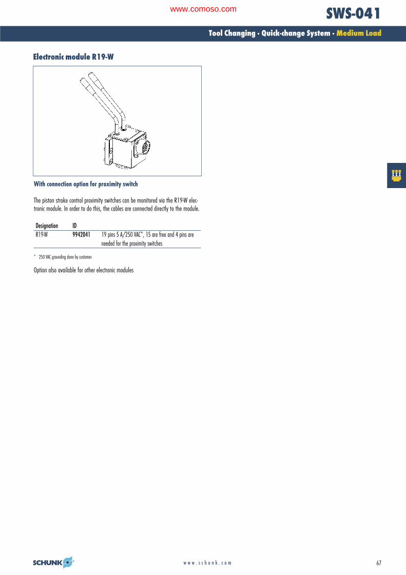
Electronic module R19-W
With connection option for proximity switch
The piston stroke control proximity switches can be monitored via the R19-W elec-tronic module. In order to do this, the cables are connected directly to the module.
Designation IDR19-W 9942041 19 pins 5 A/250 VAC*, 15 are free and 4 pins are
needed for the proximity switches
* 250 VAC grounding done by customer
Option also available for other electronic modules
02-Wechseln_RZ_0708_EN.qxd:02-Wechseln GB.qxd 25.09.2008 11:10 Uhr Seite 67
www.comoso.com

68 w w w . s c h u n k . c o m
SWS-060Tool Changing · Quick-change System · Medium Load
Technical dataDesignation SWS-060Maximum payload [kg] 75 A larger payload is possible with smaller momentsStatic moment load Mxy [Nm] 197Static moment load Mz [Nm] 294Dynamic moment load Mxy [Nm] 591Dynamic moment load Mz [Nm] 882Locking force (at 6 bar) [N] 7387 In the event of higher tensile forces the system “falls” into the self-locking positionRepeat accuracy [mm] 0.015 Tested at 1 million cyclesWeight [kg] 2.0 1.3 kg head; 0.7 kg adapterMin./max. distance on locking [mm] 5.0 No-Touch-Locking™ technology allows the parts to be coupled
without the head and the adapter touchingPneumatic energy transmission 8x pneumatic G 1/8” Max. 7 barMaximum permissible XY offset [mm] ± 2 Maximum permissible XY offset when lockingMaximum permissible angular offset [°] ± 1 Maximum permissible angular offset around the Z axis when locking
Information on moment loadSelecting the correct quick-change system depends on the moment load which the system is subject to. Proceed as follows to calculate the maximum moments.· Determine the center of gravity and the weight (m in Newtons) of your heaviest tool (gripper, adapter plate and tool)· Determine the distance (D in meters) from the center of gravity to the underside of the quick-change adapter (SWA)· Calculate the static moment (m x D)· Select a quick-change system with a permissible moment that is equal to or greater than the moment you have calculated
Robot movements can also have an effect on the change system. Dynamic moments can come into effect which are 2 – 3 times greater than the static moments you havecalculated. The SWS quick-change systems are designed for handling dynamic moments which can be up to three times greater than the static moments.
Moment load
� The dynamic moment load can be up to three timeslarger than the static moment load. Tests haveshown that the system will only begin to fail in theevent of 12-fold static moment.
Mx max. 197 NmMy max. 197 NmMz max. 294 Nm
Light and compact with an extremely highlocking forceNo-Touch-Locking™Locking without touching. Ensures that the SWS issecurely locked even when the SWK and SWA do nottouch. A maximum distance of 5 mm is possible.Patented, self-retaining locking systemA larger piston diameter and the OD locking mechanism increase the permissible moment load.Steel components made from stainless Rc 58.Air feed-through with specially developedrubber seals
Product description
02-Wechseln_RZ_0708_EN.qxd:02-Wechseln GB.qxd 26.09.2008 9:31 Uhr Seite 68
www.comoso.com

69w w w . s c h u n k . c o m
SWS-060Tool Changing · Quick-change System · Medium Load
Main views
Designation Detailed data sheetK19 19 pins, 3 A/50 V, MS connector See “SWS options” chapterK26 26 pins, 3 A/50 V, MS connector See “SWS options” chapterKM14 14-pin, (12x5 A/250 VAC* and
2x13 A/250 VAC*) See “SWS options” chapter
* 250 VAC grounding done by customer
Electrical options
The drawing shows the quick-change system in the basic version, the dimensionsdo not include the options described below.
A Locked air connectionB Unlocked air connection� Through-bore for screw connection with screw (enclosed)�� Screw connection area for options�� Bolt pitch circle�� Air feed-through
SWS-060 ExamplesOption SWK-060-000-000(000 = no option) (SWK-060, head side,
no option)K = head SWA-060-R19-000A = adapter (SWA-060, adapter plate side,
with R19 option)
How to order (example)SW -060- -000
02-Wechseln_RZ_0708_EN.qxd:02-Wechseln GB.qxd 25.09.2008 11:10 Uhr Seite 69
www.comoso.com

70 w w w . s c h u n k . c o m
SWS-060Tool Changing · Quick-change System · Medium Load
Typical set-up on the robot
� Adapter plate on ISO flange� Quick-change head SWK Quick-change adapter SWA Option 1: Electric modules (e.g. K19)� Cable connector for option 1� Option 2
Design information for adapter plateCable connectors
Cable connector for the connection between the K19 module and the cable
Straight 90°Cable connectors for ID Designation ID DesignationK19 head 0301240 KAS-19B-K-0 0301248 KAS-19B-K-90K19 adapter 0301241 KAS-19B-A-0 0301249 KAS-19B-A-90
� Tool-side connection
Adapter design recommendation. An adapter is required to seal the piston chamber.
Quick-change connector K19
Option: Miniature quick-change connector with contact protected and splash-proofcontact pins (3 Amp/50 VAC per pin).K19 = 19-pin
Designation ID Fits Description K19 head 9937328 SWK 19 pin, 3 Amp/50 VAC E option with miniature
quick-change connectorK19 adapter 9937329 SWA 19 pin, 3 Amp/50 VAC E option with miniature
quick-change connector
02-Wechseln_RZ_0708_EN.qxd:02-Wechseln GB.qxd 25.09.2008 11:10 Uhr Seite 70
www.comoso.com

71w w w . s c h u n k . c o m
SWS-060Tool Changing · Quick-change System · Medium Load
Standard adapter plates for ISO flanges
� Robot-side connection � Tool-side connection
Adapter plate A80For mounting the SWK-060 directly to a flange in accordance with ISO 9409-1-80-6-M8
Designation IDA-SWK-060-ISO-A-80 0302207
� Robot-side connection � Tool-side connection
Adapter plate A100For mounting the SWK-060 directly to a flange in accordance with ISO 9409-1-100-6-M8
Designation IDA-SWK-060-ISO-A-100 0302208
Modular quick-change rack SWM-M
The modular “medium” quick-change rack has been designed for the SWS-060 size.The system’s modular structure enables you to assemble your rack on an individualbasis. Depending on the number of tools, the storage position and tool size allowsyou to create a rack tailor-made to your application.
02-Wechseln_RZ_0708_EN.qxd:02-Wechseln GB.qxd 29.09.2008 12:04 Uhr Seite 71
www.comoso.com

72 w w w . s c h u n k . c o m
SWS-060Tool Changing · Quick-change System · Medium Load
Mode of operation of the SIPTypical set-up on the robot
when using the SIP piston stroke control
� Adapter plate on ISO flange� SIP piston stroke control Proximity switch Quick-change head SWK� Quick-change adapter SWA� Option 1 (example: K19)� Cable connector (KAS) for option 1 Option 2
Locked Unlocked
� Sensor for locked (INW 80/S 0301508 or 0301408)� Sensor for unlocked (INW 80/S 0301508 or 0301408) Sensor target
Using the piston stroke control it is possible to monitor the locked and unlockedposition of the quick-change head by means of inductive proximity switches.
Minimum height of adapter plate for SIP-060
The drawing shows the minimum height of the adapter plate needed for installinga piston stroke control.
� Suitable adapter plates for ISO flanges available on request.
Proximity switch installation position
Inductive proximity switch
Designation IDINW 80/S-M12 0301508INW 80/S-M8 0301408
H 32 mm
02-Wechseln_RZ_0708_EN.qxd:02-Wechseln GB.qxd 25.09.2008 11:10 Uhr Seite 72
www.comoso.com

73w w w . s c h u n k . c o m
SWS-060Tool Changing · Quick-change System · Medium Load
02-Wechseln_RZ_0708_EN.qxd:02-Wechseln GB.qxd 25.09.2008 11:10 Uhr Seite 73
www.comoso.com

74 w w w . s c h u n k . c o m
SWS-071Tool Changing · Quick-change System · Medium Load
Technical dataDesignation SWS-071Maximum payload [kg] 79 A larger payload is possible with smaller momentsStatic moment load Mxy [Nm] 395Static moment load Mz [Nm] 395Dynamic moment load Mxy [Nm] 1185Dynamic moment load Mz [Nm] 1185Locking force (at 6 bar) [N] 8075 In the event of higher tensile forces the system “falls” into the self-locking positionRepeat accuracy [mm] 0.015 Tested at 1 million cyclesWeight [kg] 3.1 1.8 kg head; 1.3 kg adapterMin./max. distance on locking [mm] 5.0 No-Touch-Locking™ technology allows the parts to be coupled
without the head and the adapter touchingPneumatic energy transmission 8x pneumatic G 1/4” Max. 7 barMaximum permissible XY offset [mm] ± 2 Maximum permissible XY offset when lockingMaximum permissible angular offset [°] ± 1 Maximum permissible angular offset around the Z axis when locking
Information on moment loadSelecting the correct quick-change system depends on the moment load which the system is subject to. Proceed as follows to calculate the maximum moments.· Determine the center of gravity and the weight (m in Newtons) of your heaviest tool (gripper, adapter plate and tool)· Determine the distance (D in meters) from the center of gravity to the underside of the quick-change adapter (SWA)· Calculate the static moment (m x D)· Select a quick-change system with a permissible moment that is equal to or greater than the moment you have calculated
Robot movements can also have an effect on the change system. Dynamic moments can come into effect which are 2 – 3 times greater than the static moments you havecalculated. The SWS quick-change systems are designed for handling dynamic moments which can be up to three times greater than the static moments.
Moment load
� The dynamic moment load can be up to three timeslarger than the static moment load. Tests haveshown that the system will only begin to fail in theevent of 12-fold static moment.
Mx max. 395 NmMy max. 395 NmMz max. 395 Nm
Light and compact with an extremely stronglocking forceNo-Touch-Locking™Locking without touching. Ensures that the SWS issecurely locked even when the SWK and SWA do nottouch. A maximum distance of 5 mm is possible.Patented, self-retaining locking systemA larger piston diameter and the OD locking mechanism increase the permissible moment load.Steel components made from stainless Rc 58.Air feed-through with specially developedrubber seals
Product description
02-Wechseln_RZ_0708_EN.qxd:02-Wechseln GB.qxd 26.09.2008 9:31 Uhr Seite 74
www.comoso.com
75w w w . s c h u n k . c o m
SWS-071Tool Changing · Quick-change System · Medium Load
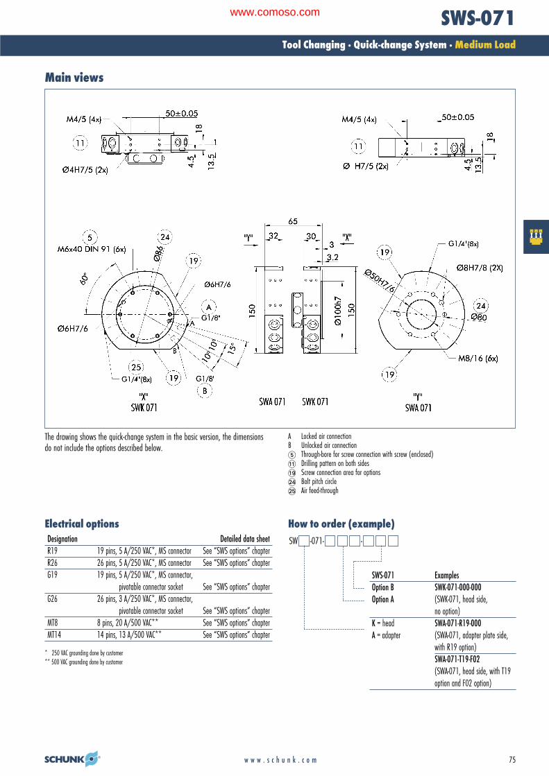
Main views
Designation Detailed data sheetR19 19 pins, 5 A/250 VAC*, MS connector See “SWS options” chapterR26 26 pins, 5 A/250 VAC*, MS connector See “SWS options” chapterG19 19 pins, 5 A/250 VAC*, MS connector,
pivotable connector socket See “SWS options” chapterG26 26 pins, 3 A/250 VAC*, MS connector,
pivotable connector socket See “SWS options” chapterMT8 8 pins, 20 A/500 VAC** See “SWS options” chapterMT14 14 pins, 13 A/500 VAC** See “SWS options” chapter
* 250 VAC grounding done by customer** 500 VAC grounding done by customer
Electrical options How to order (example)
SWS-071 ExamplesOption B SWK-071-000-000Option A (SWK-071, head side,
no option)K = head SWA-071-R19-000A = adapter (SWA-071, adapter plate side,
with R19 option)SWA-071-T19-F02(SWA-071, head side, with T19option and F02 option)
SW -071- -
The drawing shows the quick-change system in the basic version, the dimensionsdo not include the options described below.
A Locked air connectionB Unlocked air connection� Through-bore for screw connection with screw (enclosed)�� Drilling pattern on both sides�� Screw connection area for options�� Bolt pitch circle�� Air feed-through
02-Wechseln_RZ_0708_EN.qxd:02-Wechseln GB.qxd 25.09.2008 11:10 Uhr Seite 75
www.comoso.com

76 w w w . s c h u n k . c o m
SWS-071Tool Changing · Quick-change System · Medium Load
Quick-change connector R19/R26/R32Typical set-up on the robot
� Adapter plate on ISO flange� Quick-change head SWK Quick-change adapter SWA Option 1: Electric modules (e.g. R19)� Cable connector for option 1� Option 2
Option: Miniature quick-change connector with protected contact and splash-proof contact pins (5 Amp/250 VAC per pin). With tool coding as an option.R19 = 19-pin
Designation ID Fits Description R19 head 9935815 SWK 19 pins, 5 Amp/250 VAC* E option with
miniature quick-change connectorR19 adapter 9935816 SWA 19 pins, 5 Amp/250 VAC* E option with
miniature quick-change connectorR14 adapter 9935100 SWA tool coding 0-9 tools, 5 Amp/250 VAC* 14 pins
can be used by customer – see drawing, fits R19 headR10 adapter 9941385 SWA tool coding 0-99 tools, 5 Amp/250 VAC* 10 pins
can be used by customer – see drawing, fits R19 head
* 250 VAC grounding done by customer
Design information for adapter plateCable connectors
Cable connector for the connection between the R19 module and the cable
Straight 90°Cable connectors for ID Designation ID DesignationR19 head 0301240 KAS-19B-K-0 0301248 KAS-19B-K-90R19; R14; 0301241 KAS-19B-A-0 0301249 KAS-19B-A-90R10 adapter
� Tool-side connection
Adapter design recommendation. An adapter is required to seal the piston chamber.
02-Wechseln_RZ_0708_EN.qxd:02-Wechseln GB.qxd 25.09.2008 11:10 Uhr Seite 76
www.comoso.com

77w w w . s c h u n k . c o m
SWS-071Tool Changing · Quick-change System · Medium Load
Standard adapter plates for ISO flanges
� Robot-side connection � Tool-side connection
Adapter plate A80For mounting the SWK-071 directly to a flange in accordance with ISO 9409-1-80-6-M8
Designation IDA-SWK-071-ISO-A-80 0302209
� Robot-side connection � Tool-side connection
Adapter plate A100For mounting the SWK-071 directly to a flange in accordance with ISO 9409-1-100-6-M8
Designation IDA-SWK-071-ISO-A-100 0302210
Modular quick-change rack SWM-M
The modular “medium” quick-change rack has been designed for the SWS-071size. The system’s modular structure enables you to assemble your rack on an indi-vidual basis. Depending on the number of tools, the storage position and tool sizeallows you to create a rack tailor-made to your application.
02-Wechseln_RZ_0708_EN.qxd:02-Wechseln GB.qxd 25.09.2008 11:10 Uhr Seite 77
www.comoso.com

78 w w w . s c h u n k . c o m
SWS-071Tool Changing · Quick-change System · Medium Load
Mode of operation of the SIPTypical set-up on the robot
when using the SIP piston stroke control
� Adapter plate on ISO flange� SIP piston stroke control Proximity switch Quick-change head SWK� Quick-change adapter SWA� Option 1 (example: R19)� Cable connector (KAS) for option 1 Option 2
Locked Unlocked
� Sensor for locked (INW 80/S 0301508 or 0301408)� Sensor for unlocked (INW 80/S 0301508 or 0301408) Sensor target
Using the piston stroke control it is possible to monitor the locked and unlockedposition of the quick-change head by means of inductive proximity switches.
Minimum height of adapter plate for SIP-071
The drawing shows the minimum height of the adapter plate needed for installinga piston stroke control.
� Suitable adapter plates for ISO flanges available on request.
Proximity switch installation position
Inductive proximity switch
Designation IDINW 80/S-M12 0301508INW 80/S-M8 0301408
Inductive proximity switch in conjunction with R19-WDesignation IDIN-C 80/S-M8 0301477
H 34.5 mm
02-Wechseln_RZ_0708_EN.qxd:02-Wechseln GB.qxd 25.09.2008 11:10 Uhr Seite 78
www.comoso.com

w w w . s c h u n k . c o m 79
SWS-071Tool Changing · Quick-change System · Medium Load
Electronic module R19-W
With connection option for proximity switch
The piston stroke control proximity switches can be monitored via the R19-W elec-tronic module. In order to do this, the cables are connected directly to the module.
Designation IDR19-W 9942041 19 pins 5 A/250 VAC*, 15 are free and 4 pins are
needed for the proximity switches
* 250 VAC grounding done by customer
Option also available for other electronic modules
02-Wechseln_RZ_0708_EN.qxd:02-Wechseln GB.qxd 29.09.2008 12:04 Uhr Seite 79
www.comoso.com

80 w w w . s c h u n k . c o m
SWS-110Tool Changing · Quick-change System · Medium Load
Technical dataDesignation SWS-110Maximum payload [kg] 150 A larger payload is possible with smaller momentsStatic moment load Mxy [Nm] 784Static moment load Mz [Nm] 784Dynamic moment load Mxy [Nm] 2352Dynamic moment load Mz [Nm] 2352Locking force (at 6 bar) [N] 12149 In the event of higher tensile forces the system “falls” into the self-locking positionRepeat accuracy [mm] 0.015 Tested at 1 million cyclesWeight [kg] 5.9 3.9 kg head; 2.0 kg adapterMin./max. distance on locking [mm] 7.0 No-Touch-Locking™ technology allows the parts to be coupled
without the head and the adapter touchingPneumatic energy transmission 8x pneumatic G 3/8” Max. 7 barMaximum permissible XY offset [mm] ± 2 Maximum permissible XY offset when lockingMaximum permissible angular offset [°] ± 1 Maximum permissible angular offset around the Z axis when locking
Information on moment loadSelecting the correct quick-change system depends on the moment load which the system is subject to. Proceed as follows to calculate the maximum moments.· Determine the center of gravity and the weight (m in Newtons) of your heaviest tool (gripper, adapter plate and tool)· Determine the distance (D in meters) from the center of gravity to the underside of the quick-change adapter (SWA)· Calculate the static moment (m x D)· Select a quick-change system with a permissible moment that is equal to or greater than the moment you have calculated
Robot movements can also have an effect on the change system. Dynamic moments can come into effect which are 2 – 3 times greater than the static moments you havecalculated. The SWS quick-change systems are designed for handling dynamic moments which can be up to three times greater than the static moments.
Moment load
� The dynamic moment load can be up to three timeslarger than the static moment load. Tests haveshown that the system will only begin to fail in theevent of 12-fold static moment.
Mx max. 784 NmMy max. 784 NmMz max. 784 Nm
Outstanding weight/force ratioNo-Touch-Locking™Locking without touching. Ensures that the SWS issecurely locked even when the SWK and SWA do nottouch. A maximum distance of 7 mm is possible.Patented, self-retaining locking systemA larger piston diameter and the OD locking mechanism increase the permissible moment load.Steel components made from stainless Rc 58.Integrated locking monitoringfor locked and unlockedMounting option for DeviceNet moduleDirect mounting to ISO 9409-1-A125 adapterplates Available for other flangesAir feed-through with specially developedrubber seals
Product description
02-Wechseln_RZ_0708_EN.qxd:02-Wechseln GB.qxd 26.09.2008 9:31 Uhr Seite 80
www.comoso.com
81w w w . s c h u n k . c o m
SWS-110Tool Changing · Quick-change System · Medium Load
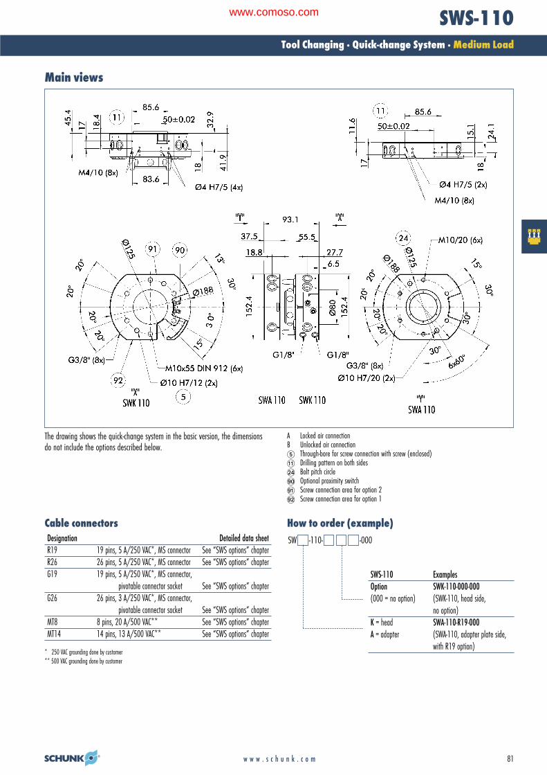
Main views
Designation Detailed data sheetR19 19 pins, 5 A/250 VAC*, MS connector See “SWS options” chapterR26 26 pins, 5 A/250 VAC*, MS connector See “SWS options” chapterG19 19 pins, 5 A/250 VAC*, MS connector,
pivotable connector socket See “SWS options” chapterG26 26 pins, 3 A/250 VAC*, MS connector,
pivotable connector socket See “SWS options” chapterMT8 8 pins, 20 A/500 VAC** See “SWS options” chapterMT14 14 pins, 13 A/500 VAC** See “SWS options” chapter
* 250 VAC grounding done by customer** 500 VAC grounding done by customer
Cable connectors
The drawing shows the quick-change system in the basic version, the dimensionsdo not include the options described below.
A Locked air connectionB Unlocked air connection� Through-bore for screw connection with screw (enclosed)�� Drilling pattern on both sides�� Bolt pitch circle�� Optional proximity switch�� Screw connection area for option 2�� Screw connection area for option 1
SWS-110 ExamplesOption SWK-110-000-000(000 = no option) (SWK-110, head side,
no option)K = head SWA-110-R19-000A = adapter (SWA-110, adapter plate side,
with R19 option)
How to order (example)SW -110- -000
02-Wechseln_RZ_0708_EN.qxd:02-Wechseln GB.qxd 25.09.2008 11:10 Uhr Seite 81
www.comoso.com
82 w w w . s c h u n k . c o m
SWS-110Tool Changing · Quick-change System · Medium Load
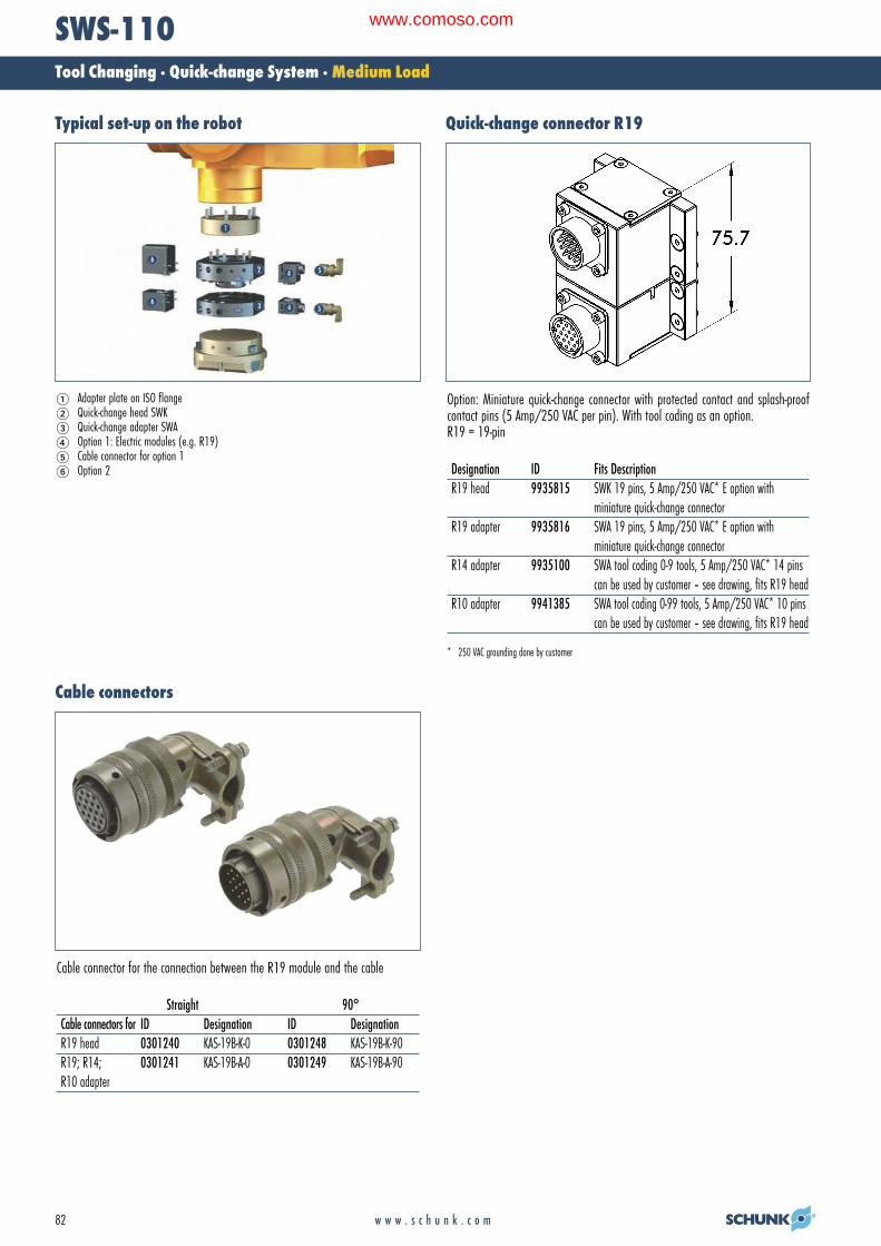
Quick-change connector R19Typical set-up on the robot
� Adapter plate on ISO flange� Quick-change head SWK Quick-change adapter SWA Option 1: Electric modules (e.g. R19)� Cable connector for option 1� Option 2
Option: Miniature quick-change connector with protected contact and splash-proof contact pins (5 Amp/250 VAC per pin). With tool coding as an option.R19 = 19-pin
Designation ID Fits Description R19 head 9935815 SWK 19 pins, 5 Amp/250 VAC* E option with
miniature quick-change connectorR19 adapter 9935816 SWA 19 pins, 5 Amp/250 VAC* E option with
miniature quick-change connectorR14 adapter 9935100 SWA tool coding 0-9 tools, 5 Amp/250 VAC* 14 pins
can be used by customer – see drawing, fits R19 headR10 adapter 9941385 SWA tool coding 0-99 tools, 5 Amp/250 VAC* 10 pins
can be used by customer – see drawing, fits R19 head
* 250 VAC grounding done by customer
Cable connectors
Cable connector for the connection between the R19 module and the cable
Straight 90°Cable connectors for ID Designation ID DesignationR19 head 0301240 KAS-19B-K-0 0301248 KAS-19B-K-90R19; R14; 0301241 KAS-19B-A-0 0301249 KAS-19B-A-90R10 adapter
02-Wechseln_RZ_0708_EN.qxd:02-Wechseln GB.qxd 25.09.2008 11:10 Uhr Seite 82
www.comoso.com

83w w w . s c h u n k . c o m
SWS-110Tool Changing · Quick-change System · Medium Load
Modular quick-change rack SWM-M
The modular “medium” quick-change rack has been designed for the SWS-110 size.The system’s modular structure enables you to assemble your rack on an individualbasis. Depending on the number of tools, the storage position and tool size allowsyou to create a rack tailor-made to your application.
Electronic module R19-R
With connector option for proximity switch
The piston stroke control proximity switches can be monitored via the R19 electronicmodule. In order to do this, the cables are connected directly to the module.
Designation IDR19-R 9942391 19 pins 5 A/250 VAC*, 15 are free and 4 pins are
needed for the proximity switches
* 250 VAC grounding done by customer
Option also available for other electronic modules
Proximity switch installation position
�� Sensor for locked�� Sensor for unlocked�� Sensor for presence monitoring
Inductive proximity switch
Designation IDIN 81/S 0302454
Standard adapter plates for ISO flanges
� Robot-side connection � Tool-side connection
Adapter plate A160For mounting the SWK-150 directly to a flange in accordance with ISO 9409-1-160-6-M10/ISO 9409-1-160-11-M12
Designation IDA-SWK-110-ISO-A-160 0302225
02-Wechseln_RZ_0708_EN.qxd:02-Wechseln GB.qxd 25.09.2008 11:10 Uhr Seite 83
www.comoso.com

84 w w w . s c h u n k . c o m
SWS-150Tool Changing · Quick-change System · Medium Load
Technical dataDesignation SWS-150Maximum payload [kg] 200 A larger payload is possible with smaller momentsStatic moment load Mxy [Nm] 1356Static moment load Mz [Nm] 1130Dynamic moment load Mxy [Nm] 4068Dynamic moment load Mz [Nm] 3390Locking force (at 6 bar) [N] 16109 In the event of higher tensile forces the system “falls” into the self-locking positionRepeat accuracy [mm] 0.015 Tested at 1 million cyclesWeight [kg] 7.5 4.8 kg head; 2.7 kg adapterMin./max. distance on locking [mm] 7.0 No-Touch-Locking™ technology allows the parts to be coupled
without the head and the adapter touchingPneumatic energy transmission 10x pneumatic G 3/8” Max. 7 barMaximum permissible XY offset [mm] ± 2 Maximum permissible XY offset when lockingMaximum permissible angular offset [°] ± 1 Maximum permissible angular offset around the Z axis when locking
Information on moment loadSelecting the correct quick-change system depends on the moment load which the system is subject to. Proceed as follows to calculate the maximum moments.· Determine the center of gravity and the weight (m in Newtons) of your heaviest tool (gripper, adapter plate and tool)· Determine the distance (D in meters) from the center of gravity to the underside of the quick-change adapter (SWA)· Calculate the static moment (m x D)· Select a quick-change system with a permissible moment that is equal to or greater than the moment you have calculated
Robot movements can also have an effect on the change system. Dynamic moments can come into effect which are 2 – 3 times greater than the static moments you havecalculated. The SWS quick-change systems are designed for handling dynamic moments which can be up to three times greater than the static moments.
Moment load
� The dynamic moment load can be up to three timeslarger than the static moment load. Tests haveshown that the system will only begin to fail in theevent of 12-fold static moment.
Mx max. 1356 NmMy max. 1356 NmMz max. 1130 Nm
Extremely high locking forcesNo-Touch-Locking™Locking without touching. Ensures that the SWS issecurely locked even when the SWK and SWA do nottouch. A maximum distance of 7 mm is possible.Patented, self-retaining locking systemA larger piston diameter and the OD locking mechanism increase the permissible moment load.Steel components made from stainless Rc 58.Air feed-through with specially developedrubber seals
Product description
02-Wechseln_RZ_0708_EN.qxd:02-Wechseln GB.qxd 26.09.2008 9:31 Uhr Seite 84
www.comoso.com

85w w w . s c h u n k . c o m
SWS-150Tool Changing · Quick-change System · Medium Load
Main views
Designation Detailed data sheetR19 19 pins, 5 A/250 VAC*, MS connector See “SWS options” chapterR26 26 pins, 5 A/250 VAC*, MS connector See “SWS options” chapterG19 19 pins, 5 A/250 VAC*, MS connector,
pivotable connector socket See “SWS options” chapterG26 26 pins, 3 A/250 VAC*, MS connector,
pivotable connector socket See “SWS options” chapterMT8 8 pins, 20 A/500 VAC** See “SWS options” chapterMT14 14 pins, 13 A/500 VAC** See “SWS options” chapter
* 250 VAC grounding done by customer** 500 VAC grounding done by customer
Cable connectors
The drawing shows the quick-change system in the basic version, the dimensionsdo not include the options described below.
A Locked air connectionB Unlocked air connection� Through-bore for screw connection with screw (enclosed)�� Drilling pattern on both sides�� Screw connection area for options�� Bolt pitch circle�� Air feed-through
SWS-150 ExamplesOption B SWK-150-000-000Option A (SWK-150, head side,
no option)K = head SWA-150-R19-F02A = adapter (SWA-150, adapter plate side,
with R19 option and F02option)SWA-150-R19-000(SWA-150, head side, with R19 option)
How to order (example)
SW -150- -
02-Wechseln_RZ_0708_EN.qxd:02-Wechseln GB.qxd 25.09.2008 11:10 Uhr Seite 85
www.comoso.com

86 w w w . s c h u n k . c o m
SWS-150Tool Changing · Quick-change System · Medium Load
Quick-change connector R19Typical set-up on the robot
� Adapter plate on ISO flange� Quick-change head SWK Quick-change adapter SWA Option 1: Electric modules (e.g. R19)� Cable connector for option 1� Option 2
Option: Miniature quick-change connector with protected contact and splash-proof contact pins (5 Amp/250 VAC per pin). With tool coding as an option.R19 = 19-pin
Designation ID Fits Description R19 head 9935815 SWK 19 pins, 5 Amp/250 VAC* E option with
miniature quick-change connectorR19 adapter 9935816 SWA 19 pins, 5 Amp/250 VAC* E option with
miniature quick-change connectorR14 adapter 9935100 SWA tool coding 0-9 tools, 5 Amp/250 VAC* 14 pins
can be used by customer – see drawing, fits R19 headR10 adapter 9941385 SWA tool coding 0-99 tools, 5 Amp/250 VAC* 10 pins
can be used by customer – see drawing, fits R19 head
* 250 VAC grounding done by customer
Design information for adapter plateCable connectors
Cable connector for the connection between the R19 module and the cable
Straight 90°Cable connectors for ID Designation ID DesignationR19 head 0301240 KAS-19B-K-0 0301248 KAS-19B-K-90R19; R14; 0301241 KAS-19B-A-0 0301249 KAS-19B-A-90R10 adapter
� Tool-side connection
Adapter design recommendation. An adapter is required to seal the piston chamber.
02-Wechseln_RZ_0708_EN.qxd:02-Wechseln GB.qxd 25.09.2008 11:10 Uhr Seite 86
www.comoso.com

87w w w . s c h u n k . c o m
SWS-150Tool Changing · Quick-change System · Medium Load
Standard adapter plates for ISO flanges
� Robot-side connection � Tool-side connection
Adapter plate A125For mounting the SWK-150 directly to a flange in accordance with ISO 9409-1-125-6-M10
Designation IDA-SWK-150-ISO-A-125 0302213
� Robot-side connection � Tool-side connection
Adapter plate A160For mounting the SWK-150 directly to a flange in accordance with ISO 9409-1-160-6-M10/ISO 9409-1-160-11-M12
Designation IDA-SWK-150-ISO-A-160 0302214
Modular quick-change rack SWM-M
The modular “medium” quick-change rack has been designed for the SWS-150size. The system’s modular structure enables you to assemble your rack on an indi-vidual basis. Depending on the number of tools, the storage position and tool sizeallows you to create a rack tailor-made to your application.
02-Wechseln_RZ_0708_EN.qxd:02-Wechseln GB.qxd 25.09.2008 11:10 Uhr Seite 87
www.comoso.com
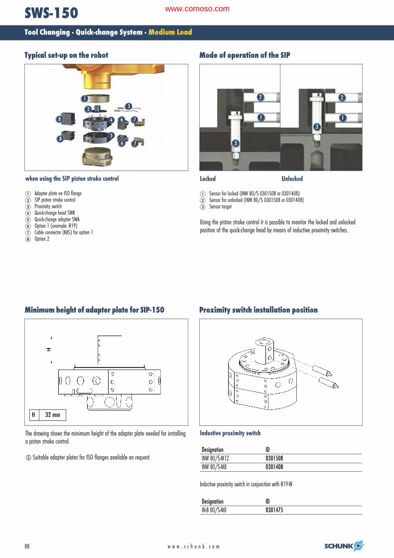
88 w w w . s c h u n k . c o m
SWS-150Tool Changing · Quick-change System · Medium Load
Mode of operation of the SIPTypical set-up on the robot
when using the SIP piston stroke control
� Adapter plate on ISO flange� SIP piston stroke control Proximity switch Quick-change head SWK� Quick-change adapter SWA� Option 1 (example: R19)� Cable connector (KAS) for option 1 Option 2
Locked Unlocked
� Sensor for locked (INW 80/S 0301508 or 0301408)� Sensor for unlocked (INW 80/S 0301508 or 0301408) Sensor target
Using the piston stroke control it is possible to monitor the locked and unlockedposition of the quick-change head by means of inductive proximity switches.
Minimum height of adapter plate for SIP-150
The drawing shows the minimum height of the adapter plate needed for installinga piston stroke control.
� Suitable adapter plates for ISO flanges available on request.
Proximity switch installation position
H 32 mm
Inductive proximity switch
Designation IDINW 80/S-M12 0301508INW 80/S-M8 0301408
Inductive proximity switch in conjunction with R19-W
Designation IDIN-B 80/S-M8 0301475
02-Wechseln_RZ_0708_EN.qxd:02-Wechseln GB.qxd 25.09.2008 11:10 Uhr Seite 88
www.comoso.com

w w w . s c h u n k . c o m 89
SWS-150Tool Changing · Quick-change System · Medium Load
Electronic module R19-W
With connector option for proximity switch
The piston stroke control proximity switches can be monitored via the R19-W elec-tronic module. In order to do this, the cables are connected directly to the module.
Designation IDR19-W 9942041 19 pins 5 A/250 VAC*, 15 are free and 4 pins are
needed for the proximity switches
* 250 VAC grounding done by customer
Option also available for other electronic modules
02-Wechseln_RZ_0708_EN.qxd:02-Wechseln GB.qxd 29.09.2008 15:21 Uhr Seite 89
www.comoso.com

90 w w w . s c h u n k . c o m
SWS-300Tool Changing · Quick-change System · Medium Load
Technical dataDesignation SWS-300Maximum payload [kg] 455 A larger payload is possible with smaller momentsStatic moment load Mxy [Nm] 3870Static moment load Mz [Nm] 2825Dynamic moment load Mxy [Nm] 11610Dynamic moment load Mz [Nm] 8475Locking force (at 6 bar) [N] 35333 In the event of higher tensile forces the system “falls” into the self-locking positionRepeat accuracy [mm] 0.015 Tested at 1 million cyclesWeight [kg] 19.1 11.8 kg head; 7.3 kg adapterMin./max. distance on locking [mm] 10 No-Touch-Locking™ technology allows the parts to be coupled without the head and the adapter
touchingPneumatic energy transmission 10x pneumatic G 3/8” Max. 7 bar, 8 are self-sealingMaximum permissible XY offset [mm] ± 3 Maximum permissible XY offset when lockingMaximum permissible angular offset [°] ± 1 Maximum permissible angular offset around the Z axis when lockingElectric energy transmission 5 x 5 A/90 V
Information on moment loadSelecting the correct quick-change system depends on the moment load which the system is subject to. Proceed as follows to calculate the maximum moments.· Determine the center of gravity and the weight (m in Newtons) of your heaviest tool (gripper, adapter plate and tool)· Determine the distance (D in meters) from the center of gravity to the underside of the quick-change adapter (SWA)· Calculate the static moment (m x D)· Select a quick-change system with a permissible moment that is equal to or greater than the moment you have calculated
Robot movements can also have an effect on the change system. Dynamic moments can come into effect which are 2 – 3 times greater than the static moments you havecalculated. The SWS quick-change systems are designed for handling dynamic moments which can be up to three times greater than the static moments.
Moment load
� The dynamic moment load can be up to three timeslarger than the static moment load. Tests haveshown that the system will only begin to fail in theevent of 12-fold static moment.
Mx max. 3870 NmMy max. 3870 NmMz max. 2825 Nm
Integrated electric module with five feed-throughsIntegrated sensor for presence monitoring The sensor issues a signal when there is a distance of1.5 mm between the head and the adapter.No-Touch-Locking™Locking without touching. Ensures that the SWS issecurely locked even when the SWK and SWA do nottouch. A maximum distance of 10 mm is possible.Patented, self-retaining locking systemA larger piston diameter and the OD locking mechanismincrease the permissible moment load.Air feed-through with specially developedrubber seals
Product description
02-Wechseln_RZ_0708_EN.qxd:02-Wechseln GB.qxd 26.09.2008 9:31 Uhr Seite 90
www.comoso.com

91w w w . s c h u n k . c o m
SWS-300Tool Changing · Quick-change System · Medium Load
Main views
Designation Detailed data sheetR19 19 pins, 5 A/250 VAC*, MS connector See “SWS options” chapterR26 26 pins, 3 A/250 VAC*, MS connector See “SWS options” chapterG19 19 pins, 5 A/250 VAC*, MS connector,
pivotable connector socket See “SWS options” chapterG26 26 pins, 3 A/250 VAC*, MS connector,
pivotable connector socket See “SWS options” chapterMT8 8 pins, 20 A/500 VAC** See “SWS options” chapterMT14 14 pins, 13 A/500 VAC** See “SWS options” chapter
* 250 VAC grounding done by customer** 500 VAC grounding done by customer
Electrical options
The drawing shows the quick-change system in the basic version, the dimensions do not include the options described below.
A Locked air connectionB Unlocked air connection� Through-bore for screw connection with
screw (enclosed)�� Drilling pattern on both sides
�� Cable connector, by special order�� Screw connection area for options�� Bolt pitch circle� Air feed-through
How to order (example)
SWS-300 ExamplesOption B SWK-300-000-000Option A (SWK-300, head side,
no option)K = head SWA-300-MT8-000A = adapter (SWA-300, adapter plate side,
with MT8 option)SWA-300-R19-F02(SWA-300, head side, with R19option and F02 option)
SW -300- -
02-Wechseln_RZ_0708_EN.qxd:02-Wechseln GB.qxd 25.09.2008 11:28 Uhr Seite 91
www.comoso.com

92 w w w . s c h u n k . c o m
SWS-300Tool Changing · Quick-change System · Medium Load
Quick-change connector R19Typical set-up on the robot
Adapter plate on ISO flange� Quick-change head SWK� Quick-change adapter SWA Option 1: Electric modules (e.g. R19)� Cable connector for option 1� Option 2
Option: Miniature quick-change connector with protected contact and splash-proofcontact pins (5 Amp/250 VAC per pin). With tool coding as an option.R19 = 19-pin
Designation ID Fits Description R19 head 9935815 SWK 19 pins, 5 Amp/250 VAC* E option with
miniature quick-change connectorR19 adapter 9935816 SWA 19 pins, 5 Amp/250 VAC* E option with
miniature quick-change connectorR14 adapter 9935100 SWA tool coding 0-9 tools, 5 Amp/250 VAC* 14 pins
can be used by customer – see drawing, fits R19 headR10 adapter 9941385 SWA tool coding 0-99 tools, 5 Amp/250 VAC* 10 pins
can be used by customer – see drawing, fits R19 head
* 250 VAC grounding done by customer
Design information for adapter plateCable connectors
Cable connector for the connection between the R19 module and the cable
Straight 90°Cable connectors for ID Designation ID DesignationR19 head 0301240 KAS-19B-K-0 0301248 KAS-19B-K-90R19; R14; 0301241 KAS-19B-A-0 0301249 KAS-19B-A-90R10 adapter
� Tool-side connection
Adapter design recommendation. An adapter is required to seal the piston chamber.
02-Wechseln_RZ_0708_EN.qxd:02-Wechseln GB.qxd 25.09.2008 11:28 Uhr Seite 92
www.comoso.com
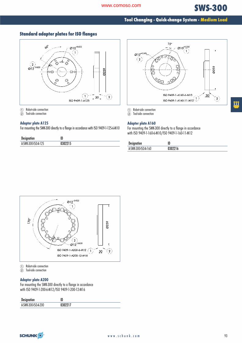
93w w w . s c h u n k . c o m
SWS-300Tool Changing · Quick-change System · Medium Load
Standard adapter plates for ISO flanges
Robot-side connection � Tool-side connection
Adapter plate A125For mounting the SWK-300 directly to a flange in accordance with ISO 9409-1-125-6-M10
Designation IDA-SWK-300-ISO-A-125 0302215
Robot-side connection � Tool-side connection
Adapter plate A160For mounting the SWK-300 directly to a flange in accordance with ISO 9409-1-160-6-M10/ISO 9409-1-160-11-M12
Designation IDA-SWK-300-ISO-A-160 0302216
Robot-side connection � Tool-side connection
Adapter plate A200For mounting the SWK-300 directly to a flange in accordance with ISO 9409-1-200-6-M12/ISO 9409-1-200-12-M16
Designation IDA-SWK-300-ISO-A-200 0302217
02-Wechseln_RZ_0708_EN.qxd:02-Wechseln GB.qxd 25.09.2008 11:28 Uhr Seite 93
www.comoso.com

94 w w w . s c h u n k . c o m
SWS-300Tool Changing · Quick-change System · Medium Load
Mode of operation of the SIPTypical set-up on the robot
when using the SIP piston stroke control
� Adapter plate on ISO flange� SIP piston stroke control� Proximity switch� Quick-change head SWK� Quick-change adapter SWA� Option 1 (example: R19)� Cable connector (KAS) for option 1 Option 2
Locked Unlocked
� Sensor for locked (INW 80/S 0301508 or 0301408)� Sensor for unlocked (INW 80/S 0301508 or 0301408)� Sensor target
Using the piston stroke control it is possible to monitor the locked and unlockedposition of the quick-change head by means of inductive proximity switches.
Minimum height of adapter plate for SIP-300
The drawing shows the minimum height of the adapter plate needed for installinga piston stroke control.
� Suitable adapter plates for ISO flanges available on request.
Proximity switch installation position
H 39 mm
Inductive proximity switch
Designation IDINW 80/S-M12 0301508INW 80/S-M8 0301408
Inductive proximity switch in conjunction with R19-W
Designation IDIN-C 80/S-M8 0301475
02-Wechseln_RZ_0708_EN.qxd:02-Wechseln GB.qxd 25.09.2008 16:32 Uhr Seite 94
www.comoso.com

w w w . s c h u n k . c o m 95
SWS-300Tool Changing · Quick-change System · Medium Load
Electronic module R19-W
With connector option for proximity switch
The piston stroke control proximity switches can be monitored via the R19-W elec-tronic module. In order to do this, the cables are connected directly to the module.
Designation IDR19-W 9942041 19 pins 5 A/250 VAC*, 15 are free and 4 pins are
needed for the proximity switches
* 250 VAC grounding done by customer
Option also available for other electronic modules
02-Wechseln_RZ_0708_EN.qxd:02-Wechseln GB.qxd 29.09.2008 15:21 Uhr Seite 95
www.comoso.com