x-plane 11 · pdf filehowever, in most cases, the actual c172 procedures could be followed...
TRANSCRIPT

1
X-Plane 11 Cessna 172
Pilot’s Operating Manual Author: Julian Lockwood ([email protected])
Copyright: Laminar Research 2017
Disclaimer The information contained in this document is for simulation use only, within the X-Plane flight simulator. This document is not
subject to revision, and has not been checked for accuracy. This document is intended for entertainment only, and may not to be
used in situations involving real-life aircraft, or real-life aviation.
Distribution
This document may be copied and distributed by Laminar Research customers and developers, for entertainment. It may also be
distributed with third-party content developed for X-Plane 11.

2
Contents Background: The Cessna 172 ........................................................................................................................ 4
Cessna 172 Skyhawk Specifications .......................................................................................................... 5
The X-Plane C172 Skyhawk ........................................................................................................................... 6
Views and Controls ....................................................................................................................................... 7
Creating “Quick Look” views ..................................................................................................................... 8
Operating the controls ............................................................................................................................ 11
Assigning peripheral devices ................................................................................................................... 13
A Tour of the Cockpit .................................................................................................................................. 15
Primary Instruments ............................................................................................................................... 15
Secondary Instruments ........................................................................................................................... 18
Avionics ................................................................................................................................................... 22
Switch Panel ............................................................................................................................................ 25
Throttle & Mixture / Pedestal ................................................................................................................. 27
Annunciator Panel ................................................................................................................................... 29
Autopilot Operation .................................................................................................................................... 30
Flight Planning ............................................................................................................................................. 32
Fuel Calculation ........................................................................................................................................... 33
Taxi Fuel .................................................................................................................................................. 33
Taxi Fuel Table ........................................................................................................................................ 33
Trip Fuel .................................................................................................................................................. 33
Trip Fuel Table ......................................................................................................................................... 33
Weight & Balance........................................................................................................................................ 34
Total Weight ............................................................................................................................................ 34
Center of Gravity (CG) ............................................................................................................................. 34
Weight and Balance Table ...................................................................................................................... 34
Configuring the Weight and Balance in X-Plane ..................................................................................... 39
Checklists .................................................................................................................................................... 40
Initial Cockpit Check ................................................................................................................................ 40
Pre-Flight Exterior Inspection ................................................................................................................. 41
Before Starting Engines ........................................................................................................................... 43
Engine Start ............................................................................................................................................. 44
Before Taxi .............................................................................................................................................. 44

3
Before Takeoff......................................................................................................................................... 45
Takeoff .................................................................................................................................................... 45
Short-Field Takeoff .................................................................................................................................. 46
Climb ....................................................................................................................................................... 46
Cruise ...................................................................................................................................................... 47
Descent ................................................................................................................................................... 47
Before Landing ........................................................................................................................................ 48
After Landing ........................................................................................................................................... 48
Engine Shutdown & Securing Aircraft ..................................................................................................... 49
Operational Speeds ..................................................................................................................................... 50
4
Background: The Cessna 172
Photo credit: Wikipedia
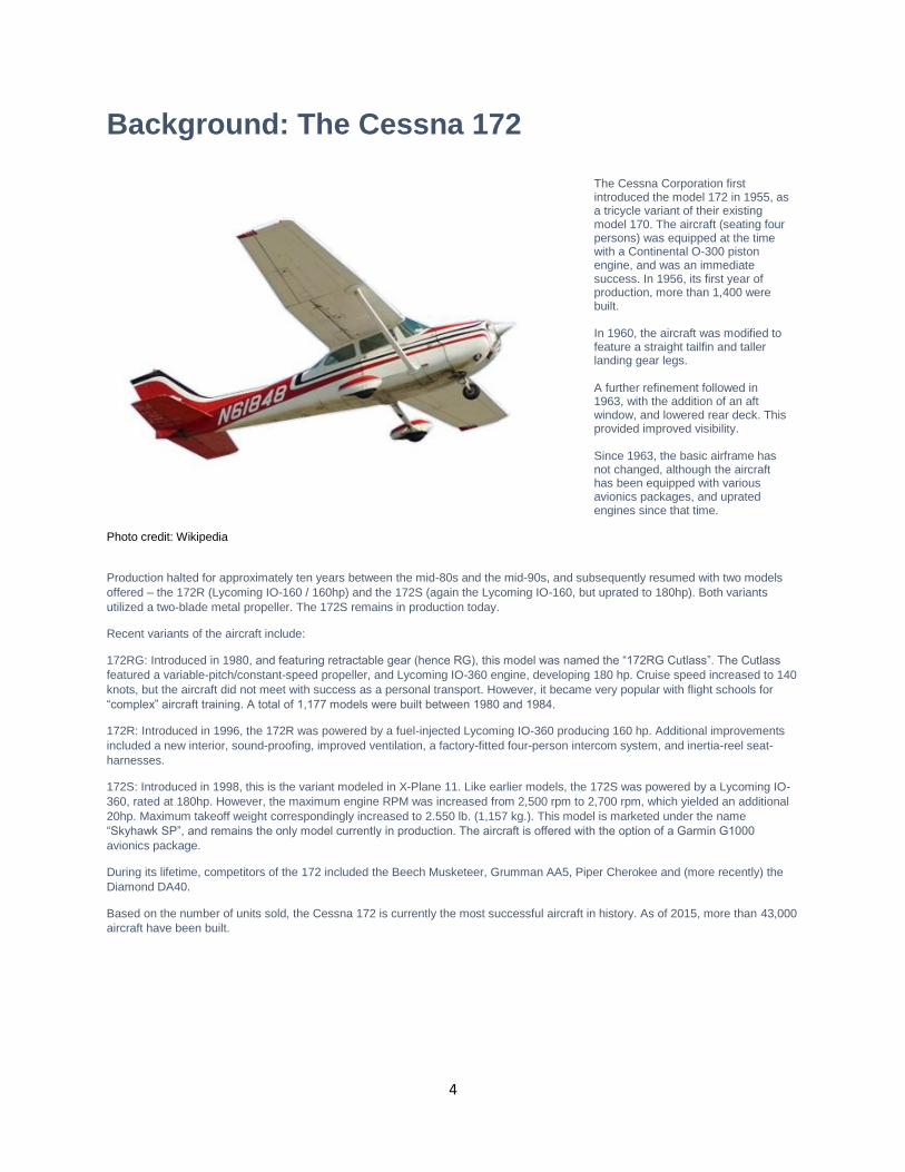
The Cessna Corporation first introduced the model 172 in 1955, as a tricycle variant of their existing model 170. The aircraft (seating four persons) was equipped at the time with a Continental O-300 piston engine, and was an immediate success. In 1956, its first year of production, more than 1,400 were built. In 1960, the aircraft was modified to feature a straight tailfin and taller landing gear legs. A further refinement followed in 1963, with the addition of an aft window, and lowered rear deck. This provided improved visibility. Since 1963, the basic airframe has not changed, although the aircraft has been equipped with various avionics packages, and uprated engines since that time.
Production halted for approximately ten years between the mid-80s and the mid-90s, and subsequently resumed with two models
offered – the 172R (Lycoming IO-160 / 160hp) and the 172S (again the Lycoming IO-160, but uprated to 180hp). Both variants
utilized a two-blade metal propeller. The 172S remains in production today.
Recent variants of the aircraft include:
172RG: Introduced in 1980, and featuring retractable gear (hence RG), this model was named the “172RG Cutlass”. The Cutlass
featured a variable-pitch/constant-speed propeller, and Lycoming IO-360 engine, developing 180 hp. Cruise speed increased to 140
knots, but the aircraft did not meet with success as a personal transport. However, it became very popular with flight schools for
“complex” aircraft training. A total of 1,177 models were built between 1980 and 1984.
172R: Introduced in 1996, the 172R was powered by a fuel-injected Lycoming IO-360 producing 160 hp. Additional improvements
included a new interior, sound-proofing, improved ventilation, a factory-fitted four-person intercom system, and inertia-reel seat-
harnesses.
172S: Introduced in 1998, this is the variant modeled in X-Plane 11. Like earlier models, the 172S was powered by a Lycoming IO-
360, rated at 180hp. However, the maximum engine RPM was increased from 2,500 rpm to 2,700 rpm, which yielded an additional
20hp. Maximum takeoff weight correspondingly increased to 2.550 lb. (1,157 kg.). This model is marketed under the name
“Skyhawk SP”, and remains the only model currently in production. The aircraft is offered with the option of a Garmin G1000
avionics package.
During its lifetime, competitors of the 172 included the Beech Musketeer, Grumman AA5, Piper Cherokee and (more recently) the
Diamond DA40.
Based on the number of units sold, the Cessna 172 is currently the most successful aircraft in history. As of 2015, more than 43,000
aircraft have been built.

5
Cessna 172 Skyhawk Specifications Engine:
Model ----------------------------------------- 1 x Lycoming IO-360-L2A (piston)
Power ----------------------------------------- 180 horsepower @ 2,700 rpm
Propeller ----------------------------------------- McCauley, 2-Bladed Fixed Pitch
Fuel:
Capacity ----------------------------------------- 53 Gallons / 318 Lbs.
Recommended fuel ----------------------------------------- 100 Octane Low Lead (100LL)
Fuel Burn (average) ----------------------------------------- 8 Gallons per hour / 30 Liters per hour
Weights and Capacities:
Max. Takeoff Weight ----------------------------------------- 2,550 lb. (1,157 kg)
Max. Landing Weight ----------------------------------------- 2,550 lb. (1,157 kg)
Basic Empty Weight ----------------------------------------- 1,640 lb. (744 kg)
Max. Gross Weight ----------------------------------------- 2,558 lb. (1088 kg)
Max. Useful Load ----------------------------------------- 918 lb. (416 kg)
Maximum Payload ----------------------------------------- 910 lb. (413 kg)
Performance:
Cruise Speed ----------------------------------------- 124 KIAS
Stall Speed (Clean) ----------------------------------------- 48 KIAS
Stall Speed (Landing Configuration) ----------------------------------------- 40 KIAS
Best Climb Rate ----------------------------------------- 730 ft. pm (223 m. pm)
Maximum Structural Speed ----------------------------------------- 129 KIAS
Landing Distance ----------------------------------------- 1,335 ft. (407 m)
Service Ceiling ----------------------------------------- 14,000 ft. (4,267 m)
Takeoff Distance ----------------------------------------- 1,630 ft. (497 m)

6
The X-Plane C172 Skyhawk
Unlike other flight simulators, X-Plane employs a technique called “blade element theory. This technique uses the actual shape of the aircraft (as modeled in the simulator), and breaks down the forces on each part separately. The force of the “air” acting on each component of the model is individually calculated, and combined, to produce extremely realistic flight. When you “fly” an airplane in X-Plane, there are no artificial rules in place to govern how the aircraft behaves. Your control inputs move the control surfaces of the aircraft, and these interact with the flow of air around it. As such, you may consider that you are really flying the aircraft. Because of this technique, an aircraft must be modeled with great accuracy in X-Plane, in order that is behave like its real-life counterpart.
This means the fuselage, wings and tail surfaces must be the right size and shape, the center of lift and center of gravity must be in
the right places, and the engine(s) must develop the right amount of power. In fact, there are a great many properties that must be
modeled correctly to achieve a high-fidelity flight model.
The Cessna 172 featured in X-Plane-11 is the “Skyhawk” variant. This aircraft has been modeled by our design team with a degree
of accuracy that ensures its flight characteristics are very like those of the real aircraft. However, despite this, some differences will
be apparent, because even the smallest factor plays into the ultimate behavior of the aircraft, both in real life, and in X-Plane. The
systems modeling of this aircraft involves some compromise too, because of the degree of complexity present in a real aircraft.
However, in most cases, the actual C172 procedures could be followed when operating the X-Plane version. Checklists are
presented later in this document (with modifications to suit a simulation platform). It is recommended that X-Plane pilots follow those
procedures to extract the maximum capability and enjoyment from this aircraft.

7
Views and Controls
The X-Plane C172 features a detailed 3-D cockpit with a great many of the primary controls and systems modeled, including: Flight
controls (yoke, rudder pedals, throttles, prop levers, condition levers), electrical systems, navigation aids, radios, autopilot,
instrument and cabin lighting, and fuel systems.
Hint: To best view some of the switches featured in this aircraft, it is helpful to hide the pilot and co-pilot yokes. This can be accomplished by clicking the base of the yoke, or by selecting “Joystick and Equipment” from the “Settings” menu, and assigning a button, or key, to the following: Operation | Toggle Yoke Visibility Use the click-spot, or the assigned button/key, to toggle the yoke view as required. This will have no effect on the yoke operation.

8
Creating “Quick Look” views
Before discussing the controls, we suggest that the pilot establish a series of “Quick Look” views that will be helpful later when
interacting with this particular aircraft. If you are not familiar with this technique, more information is available in the X-Plane Desktop
Manual.
The following “Quick Look” views are recommended for the C172, in a situation where the pilot is not using a Virtual Reality (VR)
headset, or a head tracking device. To some degree, these correspond (on the keyboard Number Pad) with their physical locations
in the cockpit, and are therefore logical and easy to recall later.
Center Console (Trim, and Fuel Selector)
Pilot Switches
Throttle and Mixture

9
Flap Lever
Pilot’s Primary Instruments
Avionics Panel Scan
ADF (Automatic Direction Finder) panel.
10
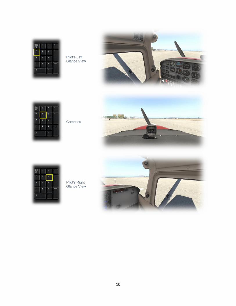
Pilot’s Left Glance View
Compass
Pilot’s Right Glance View

11
Operating the controls
This section covers the basics techniques for the operation of the controls that you will encounter in the cockpit of an X-Plane
aircraft. Control manipulators are consistent across all X-Plane 11 aircraft. However, the specific ILLUSTRATIONS in THIS chapter
may differ from YOUR aircraft.
Toggle and Rocker switches are operated with a single click of the mouse. Place the mouse pointer slightly above, or below, the center point of the switch, depending on the direction you intend to move it. A small white arrow is displayed to confirm the intended direction. Click the mouse button to complete the operation.
Levers are operated by assigning a peripheral device to the necessary axes in X-Plane (throttle, prop, mixture etc.). More information is available in the X-Plane Desktop Manual. Levers may also be operated by clicking and dragging the mouse pointer.
Some rotary dials are operated by positioning the mouse pointer on top of the control, and then a click and drag to the right, or to the left. The same can be accomplished using the mouse wheel - if one is present on your device. Other rotary controls require finer precision. When the mouse pointer is positioned slightly to the left of such a control, a counter-clockwise arrow appears. This indicates that you are ready to rotate the control counter-clockwise. Correspondingly, a clockwise arrow indicates that you are ready to rotate the control clockwise. After positioning the mouse pointer, changing the frequency in the desired direction is accomplished in two ways:
i) By rolling the mouse wheel forwards, or backwards
ii) By clicking (dragging is not
supported here) Radio and Navigation frequency rotary dials are grouped together as “twin concentric knobs”. Here, the larger rotary is used to tune the integer portion of the frequency, and the smaller rotary is used to tune the decimal portion. Each works independently, using the same technique, as described above.

12
Push buttons are operated by pointing and clicking with the mouse.
Guarded switches are used in situations where accidental activation of the switch must be prevented. To operate a guarded switch, the guard must first be opened. Do this by positioning the mouse pointer over the switch until the two vertical white arrows are displayed. Click once. If the switch is currently closed, it will open, and vice-versa. After the guard has been opened, the switch may be operated like a toggle and rocker switch (see earlier in this section).
The Yoke / Stick / Joystick is operated by assigning a peripheral device to the “roll” and “pitch” axes in X-Plane. This is discussed in greater detail later in the guide.
The Rudder Pedals are operated by assigning a peripheral device to the “yaw” axis in X-Plane. If your rudders also support toe braking, create additional assignments to the “left toe brake” and “right toe brake” axes in X-Plane. This is discussed in greater detail later in the guide. Note that you may also assign keys on your keyboard, or buttons on your external peripheral to move the rudder to the left or right, or to center the rudder.

13
Assigning peripheral devices
This section of the manual deals with an “ideal” scenario, in terms of the assignment of external computer peripherals to operate the
X-Plane C172 with the highest degree of realism. If you are missing some of these external peripherals, you may elect to choose a
different configuration that best suits your hardware.
The C172 is equipped with Yokes, for roll and pitch control. To simulate this, assign the lateral axis of your yoke (or joystick) to the “Roll” command in X-Plane, and the vertical axis to the “Pitch” command. More information is available in the X-Plane Desktop Manual.
The C172 is equipped with a single throttle – which controls the engine RPM, and (with a fixed-pitch propeller) the power output. To simulate the throttle for a C172, assign the (black) throttle lever on your quadrant to the “Throttle” property in X-Plane.
The C172 is equipped with a “Mixture” lever. This controls the fuel/air ratio to the engine. Full-forward is full-rich, and moving the lever back leans the mixture. Pull the lever to the full-back position for fuel cut-off. To simulate this, assign the (red) mixture lever on your quadrant to the “Mixture” property in X-Plane. .
14
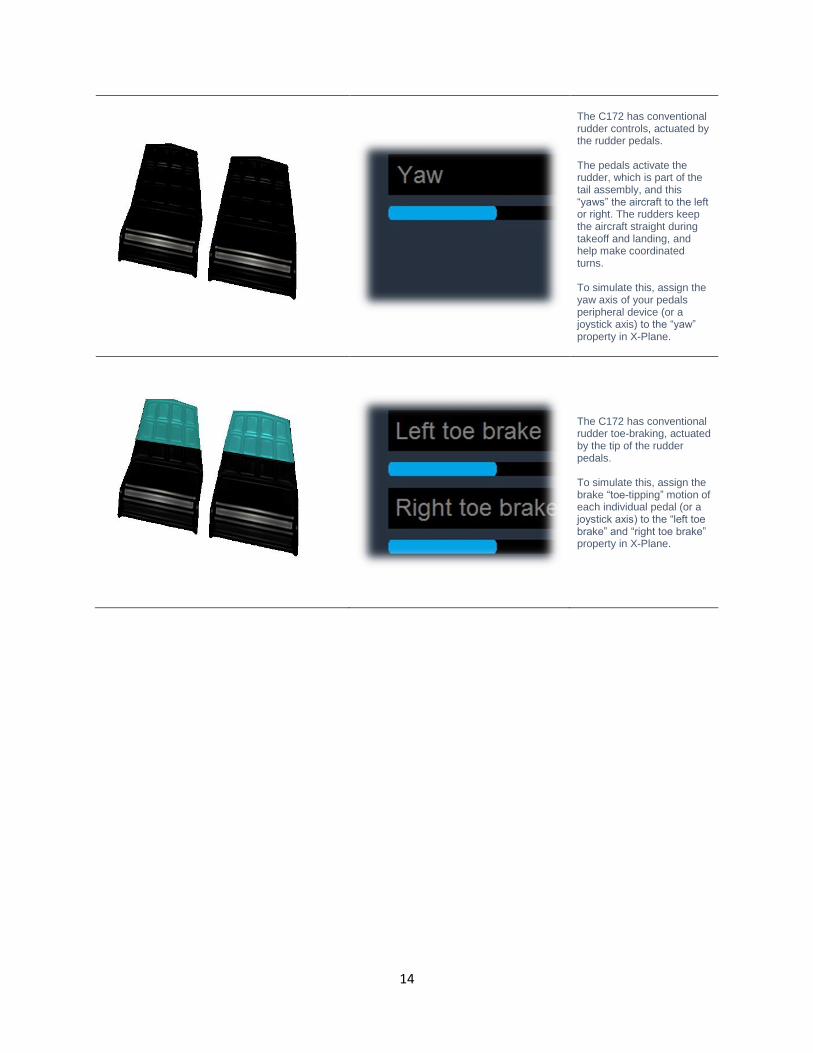
The C172 has conventional rudder controls, actuated by the rudder pedals. The pedals activate the rudder, which is part of the tail assembly, and this “yaws” the aircraft to the left or right. The rudders keep the aircraft straight during takeoff and landing, and help make coordinated turns. To simulate this, assign the yaw axis of your pedals peripheral device (or a joystick axis) to the “yaw” property in X-Plane.
The C172 has conventional rudder toe-braking, actuated by the tip of the rudder pedals. To simulate this, assign the brake “toe-tipping” motion of each individual pedal (or a joystick axis) to the “left toe brake” and “right toe brake” property in X-Plane.
15
A Tour of the Cockpit
In this section of the manual, the cockpit will be broken down into distinct functional areas, and the controls that are featured in
those areas will be identified and described. This will assist in locating the necessary instruments and controls later, when working
through the aircraft check lists, and when flying the aircraft. Only controls that are operational within the X-Plane C172 will be
presented here.
Primary Instruments
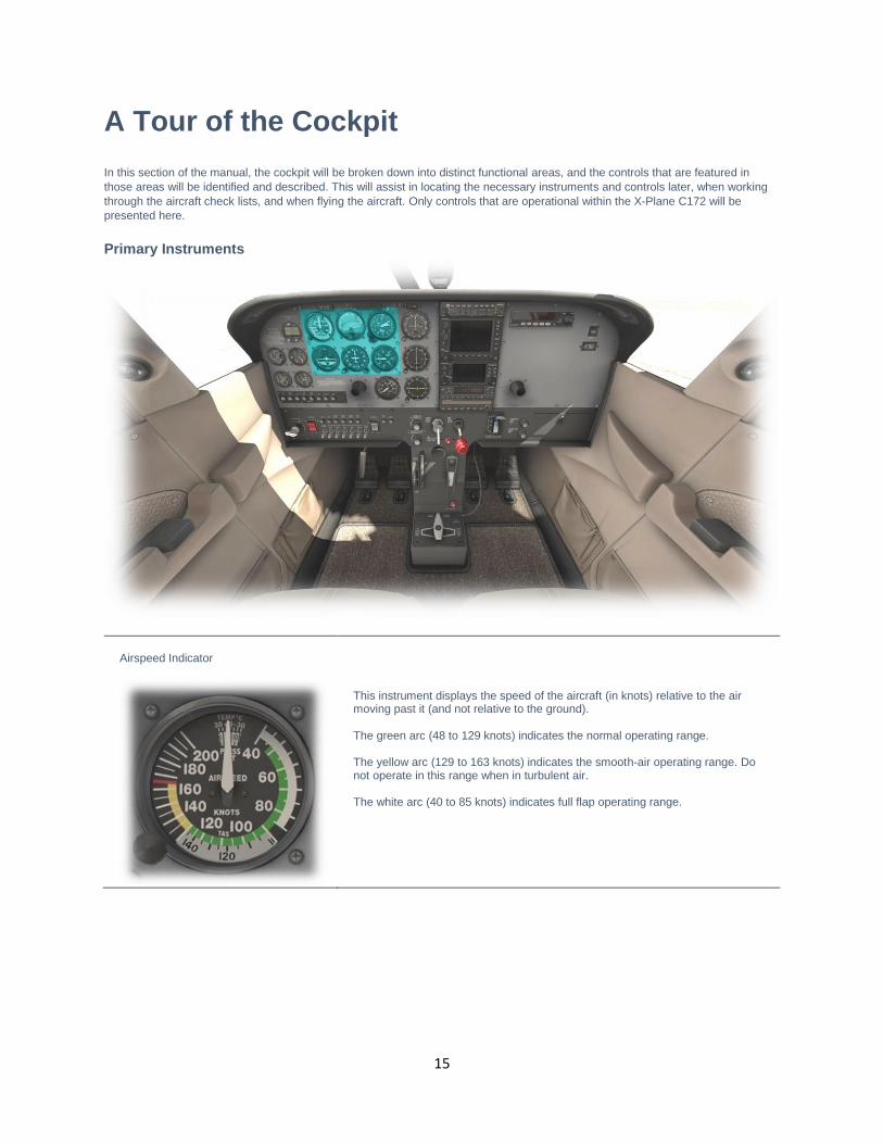
Airspeed Indicator
This instrument displays the speed of the aircraft (in knots) relative to the air moving past it (and not relative to the ground). The green arc (48 to 129 knots) indicates the normal operating range. The yellow arc (129 to 163 knots) indicates the smooth-air operating range. Do not operate in this range when in turbulent air. The white arc (40 to 85 knots) indicates full flap operating range.

16
Attitude Indicator (EADI)
This instrument displays the attitude of the aircraft relative to the horizon. This informs the pilot whether the aircraft is flying straight, or turning, and whether the aircraft is climbing, or descending. This information is crucial in “instrument conditions” - when the outside horizon is not visible.
Heading Indicator (Directional Gyro)
This instrument displays the aircraft’s (magnetic) heading. This is accomplished using a gyroscope, which is calibrated at the start of the flight, and periodically during the flight, (using the magnetic compass as a reference). This instrument uses a gyroscope to maintain the correct heading, and must be calibrated at the start of the flight by setting the heading to that indicated by the magnetic compass. Use the rotary control at the lower-left (labeled ‘Push’) to accomplish this. Because gyroscopes tend to ‘precess’ over time, the heading should be periodically reset – again using the magnetic compass, when in level flight. The rotary control at the lower-right corner is used to set the ‘Heading Bug’. This is used in conjunction with the autopilot (see later) to maintain the desired heading.
Turn Coordinator
This instrument informs the pilot of both the rate of turn, and whether the aircraft is slipping sideways during a turn. The “L” (left) and “R” (right) indicators at the four and six o-clock locations on the dial correspond with a “two-minute turn”, which is considered ideal when maneuvering an aircraft in instrument conditions. When the wings of the white aircraft in the center of the dial intersect with these markings (during a turn), it will take exactly 2 minutes for the aircraft to make a 360 degree turn back to its original course. The floating ball is used to assist the pilot in making a “coordinated turn”, so the aircraft does not slip to the side, but instead follows the desired course. If the ball moves to the right, depress the right (rudder) pedal, until the ball is centered again. Correspondingly, if the ball moves to the left, depress the left (rudder) pedal, until the ball is centered again. When the ball is centered, the aircraft is making a coordinated turn.

17
Altimeter
The altimeter displays the altitude above sea level (not the altitude above the ground). This model combines a digital and analog presentation. Altimeters use barometric pressure to determine altitude. As such, they must be calibrated at the start of the flight, and periodically re-calibrated during the flight, to account for the current local conditions. To calibrate this instrument, the pilot must set the published barometric pressure at his current location. This setting is also displayed here, both in millibars, and inches of mercury.
Vertical Speed Indicator
This instrument informs the pilot of the rate of climb, or the rate of descent, in terms of thousands of feet per minute.

18
Secondary Instruments
Chronometer
This instrument supports four modes: Universal Time (UT) Local Time (LT) Flight Time (FT – total in this aircraft to date) Elapsed Time (ET) Also displayed are the outside air temperature (O.A.T) in degrees Fahrenheit, and the battery voltage. Cycling through each of the chronometer modes is accomplished by clicking the “SELECT” button. Starting and stopping the elapsed time is accomplished by clicking the “CONTROL” button. Resetting the elapsed time is accomplished by clicking BETWEEN the two buttons.
Fuel
This instrument displays the fuel remaining (Gallons) in the left and right (wing) tanks.

19
Exhaust Gas Temperature and Fuel Flow
Exhaust Gas Temperature is measured by a thermocouple that intrudes into the exhaust stream. The red needle may be adjusted by the pilot to the peak observed EGT (on this or previous flights) using the rotary control on the left-side of the gauge. Once set, the optimum engine performance may be obtained when the actual EGT is slightly below the peak. EGT varies with the ratio of fuel and air, which is controlled by the aircraft’s mixture control. When excess fuel is present, this is called “rich”, and when excess air is present, this is called “lean”. EGT rises with leaner mixtures, and falls with richer mixtures. By adjusting the mixture until the EGT is slightly below the peak observed EGT (manually set with the red needle), the optimum fuel-burn may be achieved. The fuel flow gauge indicates the rate that fuel is flowing into the engine (Gallons per Hour). This is impacted by both the throttle setting, and the mixture setting.
Oil Temperature and Pressure
Oil temperature is measured in degrees Fahrenheit. Normal operating range is between 100 and 245 degrees. When the temperature is below this range, excess wear or damage to the engine may occur at high RPM. If the temperature is above this range, damage to the engine is likely imminent if continued operation occurs. Oil pressure is measured in PSI (pounds per square inch). Normal operating range is 50 to 90 PSI. A low oil pressure indicates insufficient oil, and may be the result of a leak, or under-filling. A high oil pressure usually occurs in cold temperatures, or with thick oil. Excessive wear, or damage to the engine, may occur if the oil pressure is not in the normal operating range.
Vacuum Pressure and Battery Ammeter
Gyro pressure gauge, vacuum gauge, or suction gauge are all terms for the same gauge - used to monitor the vacuum developed (in Inches of Mercury) by the system that actuates the air driven gyroscopic flight instruments. When the vacuum pressure is outside the normal operating range, one or more of the primary flight instruments may become inoperable. The (battery) ammeter indicates if the alternator/generator is producing an adequate supply of electrical power. A positive reading indicates the battery is charging, and a negative reading indicates the battery is depleting.

20
Propeller RPM and Hobbs Meter
This instrument displays the RPM of the propeller, which is controlled by the throttle. The green band is the recommended operating range. The Hobbs meter indicates the cumulative time the engine has been running. This is needed for the engine maintenance schedule.
VOR1 / ILS Receiver
This instrument displays the course deviation from the desired radial of a VOR transmitter, or ILS (Instrument Landing System). This is selected via the VLOC1 frequency of the Garmin G530 device. In the case of the VOR, the desired radial is selected using the OBS rotary control. The lateral course deflection is then displayed, providing the pilot with the direction in which he needs to steer to intercept that radial. The “To/From” indicator informs the pilot if he is flying towards, or away from, the VOR transmitter. In the case of an ILS, both the lateral and vertical course deflection is displayed, providing the pilot with the direction to steer to intercept the localizer, and if the aircraft is above, or below, the glideslope.
VOR2 Receiver
This instrument displays the course deviation from the desired radial of a VOR transmitter. This is selected via the VLOC2 frequency of the Garmin G430 device. The desired radial is selected using the OBS rotary control. The lateral course deflection is then displayed, providing the pilot with the direction in which he needs to steer to intercept that radial. The “To/From” indicator informs the pilot if he is flying towards, or away from, the VOR transmitter.

21
ADF (Automatic Direction Finder) Receiver
This instrument displays a direct bearing to or from a selected NDB (Non-Directional Beacon). The frequency is selected via the ADF panel on the upper-right-side of the instrument panel (described later). NDBs are simple radio transmitters. As such, the ADF instrument can also provide bearing information to non-aviation related transmitters, such as commercial radio stations, or any other radio source operating within the appropriate bandwidth.

22
Avionics
Audio Switching Panel
This panel is used to enable or disable audio from the selected radio and navigation devices. Audio will be in the form of speech from ATC communications (COM1, COM2, etc.), or Morse from Navigation aids (NAV1, NAV2, etc.). Each navigation aid (VOR, NDB, ILS, MKR (marker) has a Morse code identifier, to confirm the frequency selection is correct.
GNS 530
The GNS 530 is Laminar Research’s interpretation of the Garmin 530 series of GPS (Global Positioning System) receivers. This unit provides the pilot with the ability to input a pre-determined flight plan, which is then presented in ‘plan’ view on the display. The pilot may elect to follow the course either manually, or using the autopilot. Instructions for operating the Laminar Research GPS units can be found in separate (dedicated) manuals

23
GNS 430
The GNS 430 is Laminar Research’s interpretation of the Garmin 430 series of GPS (Global Positioning System) receivers. This unit provides the pilot with the ability to input a pre-determined flight plan, which is then presented in ‘plan’ view on the display. The pilot may elect to follow the course either manually, or using the autopilot. Instructions for operating the Laminar Research GPS units can be found in separate (dedicated) manuals.
Transponder Panel
The transponder works in conjunction with ATC radar, to identify the aircraft to controllers. When operating in controlled airspace, each aircraft is provided with a unique transponder code to accomplish this. Use the push-buttons to set the transponder code. Set the transponder to STBY when setting and operating on the ground, and ON, or ALT, when airborne. ALT mode reports both location and altitude. The IDENT button highlights your location to the controller, and should only be used when instructed.
Autopilot Panel
Autopilot features, and operation, are described later in this guide.

24
Automatic Direction Finder (ADF) Panel
The Automatic Direction Finder (ADF) is a radio receiver that can be tuned to any Non-Directional Beacon (NDB) that is within range. It provides a direct course to or from the radio source, which is displayed by the needle on the ADF instrument (see Secondary Instruments).
NAV / GPS Button This button provides a convenient way to toggle the GPS 530 unit between VLOC (Nav) mode and GPS mode. Select VLOC (Nav) Mode to use radio navigation aids, such as VORs and ILS approaches. Select GPS Mode when navigating according to a flight plan that has been programmed into the G530.
25
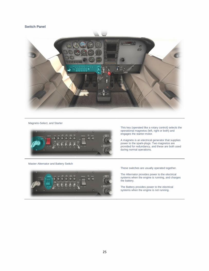
Switch Panel
Magneto-Select, and Starter
This key (operated like a rotary control) selects the operational magnetos (left, right or both) and engages the starter-motor. A magneto is an electrical generator that supplies power to the spark-plugs. Two magnetos are provided for redundancy, and these are both used during normal operations.
Master Alternator and Battery Switch
These switches are usually operated together. The Alternator provides power to the electrical systems when the engine is running, and charges the battery. The Battery provides power to the electrical systems when the engine is not running.
26
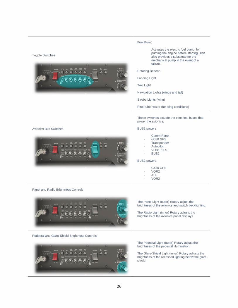
Toggle Switches
Fuel Pump
Activates the electric fuel pump, for priming the engine before starting. This also provides a substitute for the mechanical pump in the event of a failure.
Rotating Beacon Landing Light Taxi Light Navigation Lights (wings and tail) Strobe Lights (wing) Pitot-tube heater (for icing conditions)
Avionics Bus Switches
These switches actuate the electrical buses that power the avionics. BUS1 powers:
- Comm Panel - G530 GPS - Transponder - Autopilot - VOR1 / ILS - BUS2
BUS2 powers:
- G430 GPS - VOR2 - ADF - VOR2
Panel and Radio Brightness Controls
The Panel Light (outer) Rotary adjust the brightness of the avionics and switch backlighting. The Radio Light (inner) Rotary adjusts the brightness of the avionics panel displays
Pedestal and Glare-Shield Brightness Controls
The Pedestal Light (outer) Rotary adjust the brightness of the pedestal illumination. The Glare-Shield Light (inner) Rotary adjusts the brightness of the recessed lighting below the glare-shield.

27
Throttle & Mixture / Pedestal
Throttle Lever
The C172 is equipped with a single throttle that controls the engine power, and the propeller RPM. When in flight, increase the throttle to initiate a climb, and decrease the throttle to initiate a descent.
Mixture Lever
The C172 is equipped with a single mixture control that alters the ratio of fuel and air entering the engine. Pull backwards to lean the mixture. Push forwards to richen the mixture. As altitude increases, the pilot leans the mixture to compensate for the decrease in air-density. Mixture also affects the engine temperature, and fuel consumption. See also the EGT / Fuel flow gauge in Secondary Instruments).

28
Elevator Trim
The Elevator Trim can be adjusted using the mouse-wheel (or mapped to a peripheral device). Elevator trim alleviates the need for the pilot to maintain backward, or forward pressure on the yoke. Trim is also used to set the desired airspeed in this aircraft. Trim up for reduced airspeed, and down for increased airspeed.
Fuel Selector
Used to select the desired fuel tank(s) supplying fuel to the engine. Options are:
- Both (tanks) - Right (tank) - Left (tank)
Normal operating procedure is to utilize both tanks simultaneously. However, there may be a need to select a single tank, in the event there is an uneven weight distribution of fuel between the two tanks, or when fueling the aircraft on uneven ground.

29
Annunciator Panel
This panel features a group of lights that indicate the status of the aircraft’s equipment or systems. Red indicators are warnings, and
amber indicators are cautions.
A test switch is located immediately to the right of the annunciator panel. Depressing this switch illuminates every light in the panel,
to confirm each one is working prior to the flight.
1 L FUEL R
Severity: Caution Left / Right Fuel Pressure: Indicates a drop in fuel pressure from either the left, or right fuel supply. This usually occurs in the event of fuel starvation, a fuel leak, or the failure of a fuel pump.
2 OIL PRESS
Severity: Warning Oil Pressure: Engine oil pressure is low. This occurs when there is insufficient oil present, or in the event of an oil-pump failure.
3 L VAC R
Severity: Caution Left / Right Vacuum system pressure is low. Indicates a drop in vacuum pressure from the left or right vacuum pump. This may occur at low engine RPM, or when there is a legitimate failure of the vacuum system. In the event of a failure, the following instruments will be affected:
- Airspeed Indicator - Altimeter - Vertical Speed Indicator - Attitude Indicator - Heading Indicator - Turn Coordinator
4 VOLTS
Severity: Warning Low Voltage: Indicates the alternator is not generating enough voltage to keep the battery charged. This may indicate an alternator failure. The battery will gradually deplete, leading to an electrical system failure.

30
Autopilot Operation
1
AP
Autopilot On/Off This is a toggle button, used to engage and dis-engage the autopilot system respectively. When the autopilot is initially engaged, the pilot still has full manual control of the aircraft, because no autopilot mode has yet been selected.
2
HDG
Heading Mode This is a toggle button, used to engage and dis-engage HEADING mode respectively. When this mode is engaged, the autopilot will turn the aircraft to the heading selected by the pilot. The pilot may select the desired heading using the “Heading Bug” which is a feature of the Heading Indicator (Directional Gyro). See Primary Instruments.
3 NAV
Navigation Mode If the Garmin G530 is currently in “GPS” mode, selecting this autopilot mode will direct the aircraft laterally, according to any flight plan currently programmed into the GPS. If the Garmin G530 is in “VLOC” (VOR/Localizer) mode, selecting this autopilot mode will direct the aircraft to fly to, or from, the chosen radio navigation aid.

31
4 APR
Approach Mode This mode is engaged to fly an ILS approach. NAV mode will also engage by default. The autopilot will capture the localizer and glideslope associated with the chosen ILS frequency, provided the G530 is in VLOC mode. When the aircraft captures the glideslope, and begins descending, the pilot is responsible for managing the airspeed (using the throttle). Note: The autopilot may not capture the ILS if extreme maneuvers are required to accomplish this. The pilot should therefore position the aircraft close to the localizer and glideslope, and in stable flight, before engaging APR mode.
5 REV
Reverse Mode Use this mode when flying an ILS-localizer back-course. The principle is otherwise the same as APR (Approach) Mode.
6 ALT
Altitude Mode Select this mode to hold the current altitude. This may also be accomplished using VS mode (where VS is set to ‘00’).
7 VS
Vertical Speed Mode Select this mode to maintain a desired vertical speed (when climbing or descending). Use the rotary control to set the desired rate (in units of 100 feet per minute). For example, if you wish to descend at a rate of 500 feet per minute, use the rotary control to select ‘-05’. Caution is required when using this mode, to maintain a safe airspeed. The selected rate of climb/descent may exceed the performance capability of the aircraft, resulting in airspeed that is too low, or too high. The pilot must manage this manually.

32
Flight Planning
Flight planning is the process of determining a route from origin to destination that considers fuel requirements, terrain avoidance,
Air Traffic Control, aircraft performance, airspace restrictions and notices to airmen (NOTAMS).
General information about flight plans is available on Wikipedia at http://en.wikipedia.org/wiki/Flight_planning
Flight plans can be generated by onboard computers if the aircraft is suitably equipped. If not, simulation pilots may elect to use an
online flight planner. A web search for the phrase “Flight Planner” will yield a great many options, many of which are free services.
A good online flight planner will utilize the origin and destination airports, together with the aircraft type and equipment, the weather
conditions, the chosen cruise altitude, known restrictions along the route, current NOTAMS, and other factors to generate a suitable
flight plan. The waypoints incorporated into the flight plan can be subsequently input into the aircraft’s Flight Management Computer
(FMS), or Global Positioning System (GPS). Some online flight planners provide the option to save the plan as an X-Plane
compatible file, with an ‘fms’ extension. A saved flight plan can be loaded into the GPS or Flight Management Computer unit
featured in the C172.
It is recommended the pilot generate a flight plan for the chosen route before using the GPS units.
Instructions for operating the Laminar Research GPS units can be found in separate (dedicated) manuals.

33
Fuel Calculation
Note: All calculations here are based on the X-Plane C172, and NOT the real-life C172. Differences may exist.
Taxi Fuel
The estimated fuel required to taxi from the startup location to the active runway at the origin, plus the estimated fuel required to taxi
from the active runway to the shutdown location at the destination. This is dependent on the ground route that will be followed, and
the traffic at the airports in question. The pilot must use his or her judgement to determine the total taxi time. Once this has been
estimated, use the following lookup table to determine the amount of fuel required.
Taxi Fuel Table
Taxi Time (minutes) Fuel Flow (lbs. / hour) Total Fuel Weight (lbs.)
10 24 4
20 24 8
30 24 12
40 24 16
50 24 20
60 24 24
Trip Fuel
The estimated fuel required to complete the cruise portion of the trip. This will be a factor of the expected elapsed time for the flight,
which will be provided by your chosen online flight planner. Once this has been calculated, use the following lookup table to
determine the amount of fuel required.
Trip Fuel Table
Flight Time (minutes) Fuel Flow (lbs. / hour) Total Fuel Weight (lbs.)
20 48 16
40 48 32
60 48 48
80 48 64
100 48 80
120 48 96
140 48 112
160 48 128
180 48 144
200 48 160
220 48 176
240 48 192
260 48 208
280 48 224
300 48 240
320 48 256
340 48 272
360 48 288
380 48 304
400 48 320
420 48 336
34
Weight & Balance
Proper weight and balance control is crucial to the safe operation of any aircraft. Two elements are vital in this process:
Total Weight
This must be no greater than the maximum allowed by the regulatory body that oversees the operation of the aircraft. In the United
States, this is the Federal Aviation Administration (FAA).
Center of Gravity (CG)
The point at which all weight is concentrated. This must be within the allowable range published for the aircraft in question.
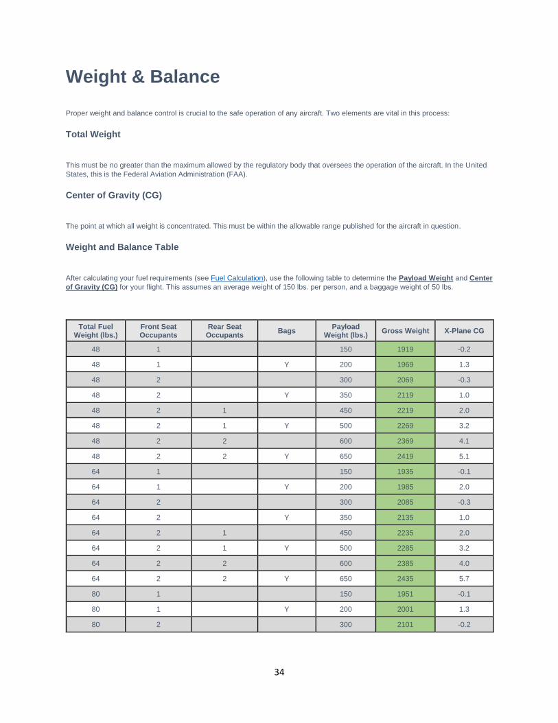
Weight and Balance Table
After calculating your fuel requirements (see Fuel Calculation), use the following table to determine the Payload Weight and Center
of Gravity (CG) for your flight. This assumes an average weight of 150 lbs. per person, and a baggage weight of 50 lbs.
Total Fuel Weight (lbs.)
Front Seat Occupants
Rear Seat Occupants
Bags Payload
Weight (lbs.) Gross Weight X-Plane CG
48 1 150 1919 -0.2
48 1 Y 200 1969 1.3
48 2 300 2069 -0.3
48 2 Y 350 2119 1.0
48 2 1 450 2219 2.0
48 2 1 Y 500 2269 3.2
48 2 2 600 2369 4.1
48 2 2 Y 650 2419 5.1
64 1 150 1935 -0.1
64 1 Y 200 1985 2.0
64 2 300 2085 -0.3
64 2 Y 350 2135 1.0
64 2 1 450 2235 2.0
64 2 1 Y 500 2285 3.2
64 2 2 600 2385 4.0
64 2 2 Y 650 2435 5.7
80 1 150 1951 -0.1
80 1 Y 200 2001 1.3
80 2 300 2101 -0.2

35
Total Fuel Weight (lbs.)
Front Seat Occupants
Rear Seat Occupants
Bags Payload
Weight (lbs.) Gross Weight X-Plane CG
80 2 Y 350 2151 1.1
80 2 1 450 2251 2.1
80 2 1 Y 500 2301 3.2
80 2 2 600 2401 4.0
80 2 2 Y 650 2451 5.1
96 1 150 1967 0.0
96 1 Y 200 2017 1.4
96 2 300 2117 -0.2
96 2 Y 350 2167 1.1
96 2 1 450 2267 2.1
96 2 1 Y 500 2317 3.3
96 2 2 600 2417 4.1
96 2 2 Y 650 2467 5.1
112 1 150 1983 0.0
112 1 Y 200 2033 1.4
112 2 300 2133 -0.1
112 2 Y 350 2183 1.2
112 2 1 450 2283 2.1
112 2 1 Y 500 2333 3.3
112 2 2 600 2433 4.1
112 2 2 Y 650 2483 5.1
128 1 150 1999 0.1
128 1 Y 200 2049 1.5
128 2 300 2149 -0.1
128 2 Y 350 2199 1.2
128 2 1 450 2299 2.2
128 2 1 Y 500 2349 3.3
128 2 2 600 2449 4.1
128 2 2 Y 650 2499 5.2
144 1 150 2015 0.1
144 1 Y 200 2065 1.5
144 2 300 2165 0.0
144 2 Y 350 2215 1.2
144 2 1 450 2315 2.2
144 2 1 Y 500 2365 3.3
144 2 2 600 2465 4.1
144 2 2 Y 650 2515 5.2

36
Total Fuel Weight (lbs.)
Front Seat Occupants
Rear Seat Occupants
Bags Payload
Weight (lbs.) Gross Weight X-Plane CG
160 1 150 2031 0.2
160 1 Y 200 2081 1.6
160 2 300 2181 0.0
160 2 Y 350 2231 1.3
160 2 1 450 2331 2.2
160 2 1 Y 500 2381 3.4
160 2 2 600 2481 4.2
160 2 2 Y 650 2531 5.2
176 1 150 2047 0.2
176 1 Y 200 2097 1.6
176 2 300 2197 0.0
176 2 Y 350 2247 1.3
176 2 1 450 2347 2.2
176 2 1 Y 500 2397 3.4
176 2 2 600 2497 4.2
176 2 2 Y 650 2547 5.2
192 1 150 2063 0.3
192 1 Y 200 2113 1.6
192 2 300 2213 0.1
192 2 Y 350 2263 1.3
192 2 1 450 2363 2.3
192 2 1 Y 500 2413 3.4
192 2 2 600 2513 4.2
192 2 2 Y 650 2563 5.2
208 1 150 2079 0.3
208 1 Y 200 2129 1.7
208 2 300 2229 0.1
208 2 Y 350 2279 1.4
208 2 1 450 2379 2.3
208 2 1 Y 500 2429 3.4
208 2 2 600 2529 4.2
208 2 2 Y 650 2579 5.2
224 1 150 2095 0.4
224 1 Y 200 2145 1.7
224 2 300 2245 0.2
224 2 Y 350 2295 1.4
224 2 1 450 2395 2.3

37
Total Fuel Weight (lbs.)
Front Seat Occupants
Rear Seat Occupants
Bags Payload
Weight (lbs.) Gross Weight X-Plane CG
224 2 1 Y 500 2445 3.5
224 2 2 600 2545 4.2
224 2 2 Y 650 2595 5.2
240 1 150 2111 0.4
240 1 Y 200 2161 1.7
240 2 300 2261 0.2
240 2 Y 350 2311 1.5
240 2 1 450 2411 2.4
240 2 1 Y 500 2461 3.5
240 2 2 600 2561 4.3
240 2 2 Y 650 2611 5.3
256 1 150 2127 0.5
256 1 Y 200 2177 1.8
256 2 300 2277 0.3
256 2 Y 350 2327 1.5
256 2 1 450 2427 2.4
256 2 1 Y 500 2477 3.5
256 2 2 600 2577 4.3
256 2 2 Y 650 2627 5.3
272 1 150 2143 0.5
272 1 Y 200 2193 1.8
272 2 300 2293 0.3
272 2 Y 350 2343 1.5
272 2 1 450 2443 2.4
272 2 1 Y 500 2493 3.5
272 2 2 600 2593 4.3
272 2 2 Y 650 2643 5.3
288 1 150 2159 0.5
288 1 Y 200 2209 1.8
288 2 300 2309 0.4
288 2 Y 350 2359 1.6
288 2 1 450 2459 2.5
288 2 1 Y 500 2509 3.6
288 2 2 600 2609 4.3
288 2 2 Y 650 2659 5.3
304 1 150 2175 0.6
304 1 Y 200 2225 1.9

38
Total Fuel Weight (lbs.)
Front Seat Occupants
Rear Seat Occupants
Bags Payload
Weight (lbs.) Gross Weight X-Plane CG
304 2 300 2325 0.4
304 2 Y 350 2375 1.6
304 2 1 450 2475 2.5
304 2 1 Y 500 2525 3.6
304 2 2 600 2625 4.3
304 2 2 Y 650 2675 5.3
320 1 150 2191 0.6
320 1 Y 200 2241 1.9
320 2 300 2341 0.4
320 2 Y 350 2391 1.7
320 2 1 450 2491 2.5
320 2 1 Y 500 2541 3.6
320 2 2 600 2641 4.3
320 2 2 Y 650 2691 5.3
336 1 150 2207 0.7
336 1 Y 200 2257 1.9
336 2 300 2357 0.5
336 2 Y 350 2407 1.7
336 2 1 450 2507 2.5
336 2 1 Y 500 2557 3.6
336 2 2 600 2657 4.4
336 2 2 Y 650 2707 5.3
39
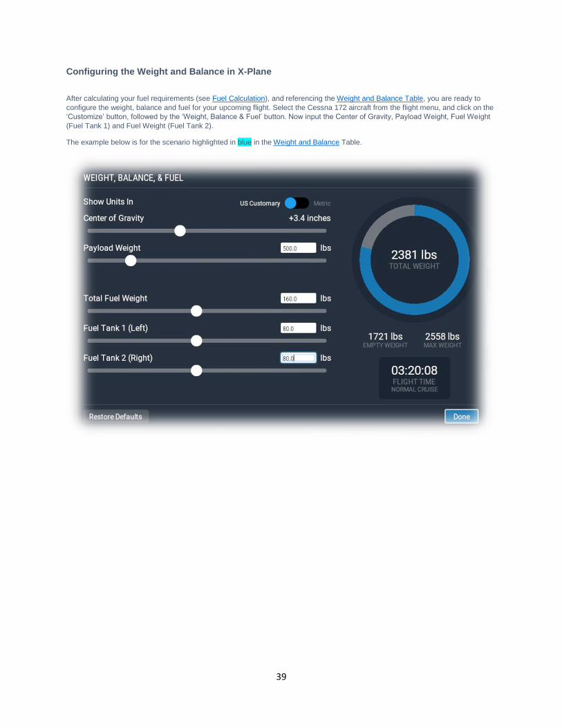
Configuring the Weight and Balance in X-Plane
After calculating your fuel requirements (see Fuel Calculation), and referencing the Weight and Balance Table, you are ready to
configure the weight, balance and fuel for your upcoming flight. Select the Cessna 172 aircraft from the flight menu, and click on the
‘Customize’ button, followed by the ‘Weight, Balance & Fuel’ button. Now input the Center of Gravity, Payload Weight, Fuel Weight
(Fuel Tank 1) and Fuel Weight (Fuel Tank 2).
The example below is for the scenario highlighted in blue in the Weight and Balance Table.

40
Checklists
The following check lists are designed with the convenience of the simulation pilot in mind, and customized to the X-Plane C172
aircraft. These differ from those of the real aircraft.
Initial Cockpit Check
Parking Brake – ON Master Switch – ON Battery Voltage – CHECK 24+ Landing Lights – ON Taxi Lights – ON Navigation Lights – ON Beacon – ON Strobes – ON Flaps – Extended

41
Pre-Flight Exterior Inspection
A Pre-Flight Inspection should always precede flight in any aircraft. The purpose of this inspection is to ensure the aircraft is in a
state of readiness for the upcoming flight.
In X-Plane, a pre-flight inspection is not merely undertaken to simulate reality, but does in fact have real purpose, because the
control surfaces of the aircraft interact directly with the airflow over and around them, just as in real life. As such, correct movement
of all control surfaces is necessary for normal flight.
Hold roll axis at full deflection. Visually check corresponding movement of ailerons.
Hold pitch axis at full deflection. Visually check corresponding movement of elevators.

42
Hold yaw axis at full deflection. Visually check corresponding movement of rudder.
Visually check flaps are extended.

43
Visually check: 1. Beacon 2. Nav Lights 3. Strobes 4. Taxi Lights 5. Landing Lights
Before Starting Engines
Exterior Inspection – COMPLETED Fuel Selector – BOTH Parking Brake – ON Lights – OFF Fuel Quantity – CHECK Power - IDLE Mixture Rich (Full Forward) Avionics Bus 1 & Bus 2 – CHECK OFF

44
Engine Start
Throttle - OPEN ¼” TO ½” Master Switch - ON Fuel Pump - ON Mixture – RICH (until stable fuel flow indication), then LEAN Beacon – ON Propeller Area – CLEAR Ignition Switch – START Mixture – RICH (advance when engine starts) Ignition Switch – BOTH Oil Pressure – CHECK Avionics Bus 1 & Bus 2 – ON Radios – ON AND SET Transponder – ON
Before Taxi
Flaps – RETRACTED. Brakes – CHECK Gyro Instruments & Compass – CHECK & SET

45
Before Takeoff
Parking Brake – SET Doors and Windows - CLOSED Flight Controls - FREE & CORRECT Flight Instruments – CHECK Altimeter – SET Fuel Selector Valve – BOTH Mixture – RICH Elevator/Rudder Trim – TAKEOFF Throttle - 1700 RPM Magnetos – CHECK Engine Instruments – CHECK Ammeter – CHECK Vacuum Pressure – CHECK Throttle – IDLE Radios – AS REQUIRED Lights – AS REQUIRED Transponder – ALT Parking Brake – RELEASE
Takeoff
Flaps – RETRACTED Throttle - FULL OPEN Elevator - ROTATE AT 55 KIAS
46
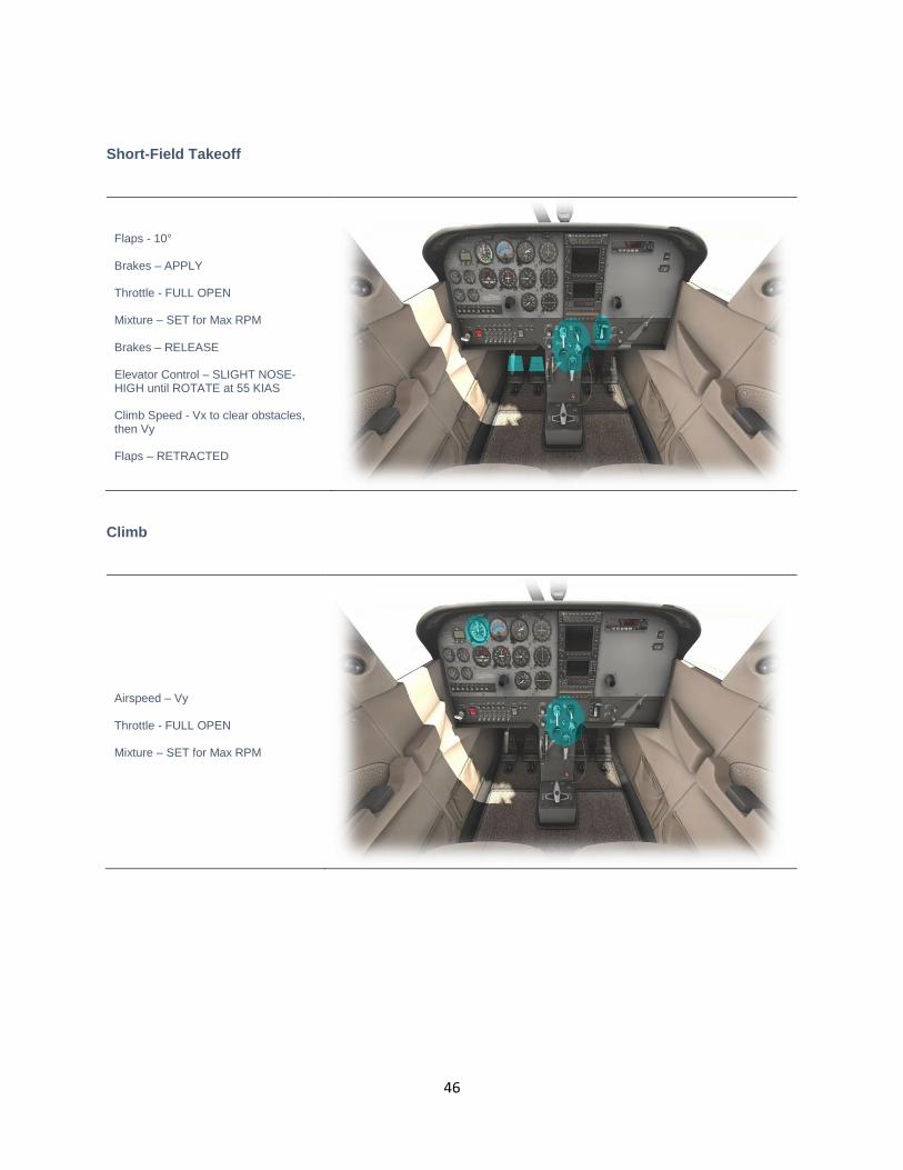
Short-Field Takeoff
Flaps - 10° Brakes – APPLY Throttle - FULL OPEN Mixture – SET for Max RPM Brakes – RELEASE Elevator Control – SLIGHT NOSE-HIGH until ROTATE at 55 KIAS Climb Speed - Vx to clear obstacles, then Vy Flaps – RETRACTED
Climb
Airspeed – Vy Throttle - FULL OPEN Mixture – SET for Max RPM

47
Cruise
RPM – 2100 to 2700 Elevator Trim - ADJUST for desired Airspeed Mixture – LEAN AS REQUIRED
Descent
Fuel Selector Valve – BOTH Mixture – RICHEN Power - AS REQUIRED

48
Before Landing
Fuel Selector Valve – BOTH Mixture – RICH Flaps – EXTENDED
After Landing
Flaps – RETRACTED Strobe Lights – OFF Trim - RESET

49
Engine Shutdown & Securing Aircraft
Parking Brake - SET Throttle - 800 to 1000 RPM Avionics – OFF Electrical Switches (except beacon) – OFF Mixture - IDLE CUTOFF Ignition Switch – OFF Master Switch – OFF Fuel Selector Valve - RIGHT TANK Hobbs and Tach Times - RECORD

50
Operational Speeds
Stall speeds, Flaps down, Power Off Vso 40 KIAS
Stall Speed, Flaps Up, Power Off Vsi/Vs1 48 KIAS
Best Angle of Climb Vx 62 KIAS
Best Climb Speed Vy 74 KIAS
Takeoff (rotate) Speed Vr 55 KIAS
Best Glide Speed Vg 68 KIAS
Maximum flaps Extended Speed - (10/30 degree) Vfe 110/85 KIAS
Maneuvering Speed Va 99 KIAS
Maximum Structural Speed Vno 129 KIAS
Never Exceed Speed Vne 163 KIAS
Enroute Climb Speed 75-85 KIAS
Maximum Demonstrated Crosswind 15 KIAS
Maximum Glide Speed 68 KIAS
Precautionary Landing with Engine Power 65 KIAS
Landing without Engine Power Flaps Up -70 KIAS
Flaps Down -65 KIAS