x-ray computed tomography using flying spot mechanical scanning
TRANSCRIPT
0
United States Patent [19] [11] Patent Number: 4,472,822 Swift [45] Date of Patent: Sep. 18, 1984
[54] X-RAY COMPUTED TOMOGRAPHY USING Primary Examiner~—Alfred E. Smith FLYING SPOT MECHANICAL SCANNING Assistant Examiner—Carolyn E. Fields MECHANISM Attorney, Agent, or Firm-Pollock, Vande Sande and
[75] Inventor: Roderick D. Swift, Belmont, Mass. Pnddy _ _ [57] ABSTRACT
[73] Ass1gnee: American Science and Engineering, _ , _ ' _
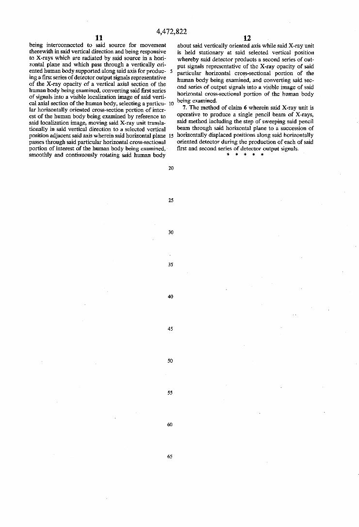
Inc" Cambridge’ Mass_ A radiant energy imaglng apparatus ‘for obta1n1ng CT scans employs an X-ray unit operatwe to produce a
[21] Appl. No.: 395,943 pencil beam of X-ray radiant energy which is caused to [22] Filed: Jul. 7’ 1982 scan in a horizontal plane through an angle, sufficiently
great to embrace a cross section of a human body bemg _ _ examined, along a single, elongated, horizontally ori
Related U-S' Apphcatwn Data ented detector forming a portion of the X-ray unit and [63] Continuation of Ser. No. 150,823, May 19, 1980, aban- located 011 the Sid6 Of the body opposite to an X-ray
cloned. source in the unit. A supporting structure, adapted to be rotated about a vertical axis, supports a human body in
Int. CL} ............................................ .. a vertical Orientation; ‘and when the system is Scanning [52] US. Cl. ...................................... .. 378/10; 378/19; in the CT mode’ the Supporting structure rotates the
_ 378/146; 378/17 human body smoothly and continuously about a verti Fleld of Search ............... .. 10, cal axis the X_I_ay unit is at a ?xed position
378/20’ 19’ 17 adjacent a horizontal section of interest of the human
[56] References Cited body. In addition t: being used as a CT slcanrier, the system can e use to generate 1ts own oca ization
U's' PATENT DOCUMENTS images and to perform digital. radiography on those Re. 28,544 9/1975 Stein et a]. ........................ .. 378/146 images and can be employed in this mode of operation 3,432,660 3/ 1969 Anger ....... .. 3755/17 to obtain anterior-posterior, lateral or oblique images at 4,034,094 4/ 1978 Frogga" - 378/10 any desired angle. In addition, when used as a CT scan 4’099’O6O 7/1978 Franke ------ -- 378/146 ner, the apparauts can be provided with several contig
uous linear detectors all of which are associated with
4:242:583 12/1980 Annis et a1_ _ 378/146 the same scanning beam, so that several _CT scans are 4,316,091 2/1982 Bernardi ............... .. .. 378/197 genérated slmPltane9usly- The effect“? Shae W‘dth °_fa 4,422,177 12/1923 Mastronardi et al. .............. .. 378/20 Pamcular feglon Of Interest can be adJuSted by combm
ing the outputs of one or more detectors in a contiguous FOREIGN PATENT DOCUMENTS group‘
2732073 l/l978 Fed. Rep. of Germany ...... .. 378/13 1528574 10/1978 United Kingdom ................ .. 378/ 19 7 Claims, 5 Drawing Figures
1|\ /
DRIVE F’
LOCALIZATION IMAGE IFIRST MODE)
[IT IMAGE [SECOND MODE).
COMPUTER] DISPLAY MEANS
' X'RAY SOURCE
AND
MECHANICAL SCANNER
3% r/AXIS 0F ROTATION
DRIVE
US. Patent Sep. 18, 1984 Sheet 1 0m ,472,822
TO STORE AND DiSPLAY
TO COMPUTER 5 AND DISPLAY
?/ “‘\
4,472,822
T0 COMPUTER
200
T l | | |
| l
PLURAL SIMULTANEOUS
OUTPUTS
U.S. atent Sap. 18, 1984 Sheet 2 of 3
l8) LINE DETECTOR \
MECHANICAL SCANNER
’ l2 ,l4
/ /
X-RAY SOURCE
\8/b 24) ; 'T
T80 /
I80]
PLURAL DETECTORS
PENCIL BEAM (CROSS SECTION)
4,472, 822 l
X-RAY COMPUTED TOMOGRAPI-IY USING FLYING SPOT MECHANICAL SCANNING
MECHANISM
This is a continuation of application Ser. No. 150,823, filed May 19, 1980, now abandoned.
BACKGROUND OF THE INVENTION
Systems have been suggested heretofore for obtain ing computed tomography (CT) scans for medical or other purposes. In general, these known systems are comparatively complex structurally, very expensive, and tend to subject a patient to a comparatively high dosage level of radiation if X-ray images of adequate quality to effect an X-ray diagnosis are to be obtained. The present invention is concerned with the provision of an apparatus which, when employed as a CT scanner, is capable of producing X-ray images which are compa rable to and in some cases better than those produced by present-day commercial CT equipment, and which achieve these results at far less cost and by subjecting the patient to a far smaller level of dosage than is cus tomary at the present time. These advantages are achieved by the provision of equipment which employs a mechanical scanner, of the general type described in Stein et a1 U.S. Pat. No. Re. 28,544 (originally U.S. Pat. No. 3,780,291) which is operative to produce a pencil beam of X-rays that scans a single efficient detector. CT equipments employing ?ying spot scanning tech
niques have been suggested heretofore. One such ar rangement is described, for example, in an article entié tled “Low-Dosage X-Ray Imaging System Employing Flying Spot X-Ray Microbeam (Dynamic Scanner)” by Tateno and Tanaka, Radiology 121: October 1976, pp 189-195. The Tateno et al system, although described as being capable of achieving quality X-ray images at lower dosages than are customarily employed in CT equipment, uses a special noncommercial X-ray tube characterized by sophisticated electron optics analo gous to those employed in high voltage electron micro scopes and electron beam machining equipment, relies on an electronic scanning technique, and contemplates the use of a two-dimensional detector. These character istics of this previously-described system make the sys tem far more expensive than the system of the present invention, which utilizes an extremely simple mechani cal scanning arrangement. In addition, inasmuch as the Tateno et al system employs a two-dimensional detec: tor, it is incapable of rejecting scattered radiation, in contrast to the system of the present invention wherein, by use of a single, ef?cient one-dimensional detector, such rejection is automatically accomplished.
Further advantages accrue to the present invention, as compared‘ to the scanning techique of Tateno et al which employs a device that produces a ?ying-spot X-ray beam by “pinhole” projection of an electronically scanned focal spot in the X-ray tube. In order to pro duce an X-ray ?eld large enough to subtend a patient cross-section for a CT scan, the beam must diverge over a considerable distance from the pinhole collimator. The required distance is equivalent to locating the pin hole at the focal spot (X-ray source) of the present invention. Since the beam cross-section at any point represents a pinhole image of the focal spot, the rela tively large distance from pinhole collimator to patient results in a relatively large beam cross-section, with a concurrent loss of resolution. The close proximity of
15
25
30
35
45
55
60,
65
2 the collimation systems to the patient in the present invention is an important improvement, since the beam size is essentially a projection of the small collimator apertures from a distant source. Another system suggested heretofore, for producing
CT images by use of a ?ying spot technique, is de scribed in Houns?eld U.S. Pat. No. 3,866,047 for “Pene trating Radiation Examining Apparatus Having A Scanning Collimator”. The Houns?eld apparatus con templates the provision of a mechanical scanning device comprising a pair of elongated shutters which are mounted for mechanical reciprocation in synchronism with one another. Each shutter member is provided with a plurality of slots which coact with one another to produce a plurality of angularly spaced radiation beams simultaneously, each beam being caused to scan through a comparatively small angle onto a compara tively small detector which is associated with that beam. The Houns?eld reciprocating shutter arrange ment is far more complex mechanically than the com paratively simple rotating collimator which is em ployed in the present invention, and requires critical alignments of the plural slots which are utilized in the spaced shutters of the Houns?eld mechanical scanner. Moreover, since Houns?eld contemplates the simulta neous generation of a plurality of angularly displaced X-ray beams, and the simultaneous scanning of all of those beams across a like plurality of detectors, the arrangement poses problems of possible loss of data at the boundaries between adjacent detectors. Two spe ci?c problems may be identi?ed: (1) The boundaries produce a geometric inef?ciency which results in wasted dose to the patient, and (2) The missing informa tion along the beam paths through the boundaries can result in artifacts in the reconstructed CT image.
Further problems with the multiple beam arrange ment of Houns?eld are related to the need for accurate matching or normalization of the plural detectors over the full dynamic range of the signal, without which severe artifacts can result in the reconstructed image. A number of phenomena, as for example cathode resistiv ity and dynode fatigue, are known to produce nonlin earities and gain changes in photomultiplier tubes, the use of which is contemplated by Hounsfield. Similar problems may occur with other plural detectors which are less ef?cient than the scintiHater-photomultiplier combination. In order to reduce the dynamic range, and thereby alleviate the normalization, Houns?eld has incorporated a “plastics block” (item 26 in his Figures) and suggests the use of a water bag ?lling the space between the plastics block and the patient. The use of such devices introduces extra expense and mechanical complexity, and results in wasted dose because of pho ton absorption (and consequent loss of information) between the patient and the detector. The present invention utilizes a single, ef?cient detec
tor and a simple mechanical scanning arrangement to obviate all these problems of the prior art.
SUMMARY OF THE INVENTION
The radiant energy imaging apparatus of the present invention comprises an X-ray system adapted to be moved rotationally as a unit about a support structure which is provided to support a body or other object to be examined by means of penetrating radiation. The X-ray unit comprises a source of X-rays located on one side of the support means, a single elongated radiant energy detector located on the opposite side of the
4,472, 822 3
support means and extending in a direction transverse to the axis of rotation of the X-ray system, and a mechani cal scanning device located between the X-ray source and the support means for con?guring radiation emitted by the source into a single pencil beam of X-rays, and for scanning that single pencil beam along the direction of elongation of the single detector through an angle which is suf?ciently large to subtend a complete cross section of a body or object on the support means. The mechanical scanning device is of the general type de scribed in Stein et al US. Pat. No. Re. 28,544 reissued Sept. 2, 1975, on the basis of US. Pat. No. 3,780,291 issued Dec. 18, 1973, and comprises a ?rst collimator for shaping radiation emitted by an X-ray source into a fan-shaped beam of X-rays, and a second collimator comprising a disc-shaped chopper Wheel fabricated of a radiation opaque material and having one or more X-ray transparent slots therein through which a pencil beam of X-rays can pass, said pencil beam being scanned along said single linear detector as the second collimator rotates. The chopper disc can take the form shown in the aforementioned Stein et al patent or, in the alternative, it can comprise a drum-shaped structure of the type shown in Jacob US. Pat. No. 4,031,401. Each of these patents is assigned to American Science and Engineering, Inc., Cambridge, Mass, the assignee of the present invention. The X-ray system, comprising the X-ray source, me
chanical scanning device, and single elongated detector, is adapted to be moved in various directions for various different purposes. The system may be moved, for ex ample, in translation along a line parallel to the axis of the support means to provide conventional radio graphic projection in a manner analogous to that achieved by the Medical MICRO-DOSE @ X-Ray system manufactured by American Science and Engi neering, Inc., Cambridge, Mass. In this mode of opera tion, because of the fact that the X-ray system is adapted to be rotated through any desired angle relative to the body support structure, images can be readily obtained as AP, PA, lateral or oblique images at any desired angle. The mode of operation described above can also be
employed to produce localization images preparatory to the CT scanning operation, i.e., the X-ray system may be translated as a unit parallel to the axis of the body support structure, and the conventional images obtained during this mode of operation can be moni tored to localize the system at a particular region of the body where a CT slice is to be taken, whereafter the X-ray system is caused to effect a continuous substan tially constant speed of rotation relative to the body support structure to obtain a CT scan of the selected slice. This relative rotation between the scanner and the object being examined can be achieved by rotating either the scanning mechanism, the object, or both. The axis of relative rotation may, moreover, be selected for any desired applications, and may be either horizontal, vertical, or at a selected angle therebetween. The system preferably includes means for adjusting
the size of the CT scan ?eld, either by mechanical ma nipulation of the fan beam and chopper wheel collima tion system, or by displacing the position of the X-ray unit or selected portions thereof relative to the axis of rotation so as to vary the spacing between said axis of rotation and the X-ray source and/or detector. The system can also be used to generate several CT
scans simultaneously by using one or more fan beam
20
25
30
40
45
50
65
4 collimation slits, all of which are traversed simulta neously, for example, by a slit in a rotating chopper wheel, and by directing a plurality of parallel flying spot beams or a single beam of suf?cient dimensions onto several contiguous linear detectors. The multiple detectors used in this con?guration, wherein each elon gated detector subtends more than the full ?eld of its CT cross-section, are not subject to the same severe normalization problems that were described with re spect to the plural detectors in the aforementioned Houns?eld patent. This is because (a) each CT slice is obtained by a single detector and (b) each detector can be calibrated many times during a single CT scan by using data obtained when the flying spot beam impinges on the detector outside the circle of its CT image ?eld. The outputs of several detectors can be employed to produce a plurality of independent CT images simulta neously, thereby reducing the time otherwise required to generate a series of CT images of one patient. This ability may be particuarly useful for the generation of so-called sagittal and coronal reconstructions from mul tiple slice data, inasmuch as obtaining the data simulta neously obviates any problems related to motion of the patient between successive scans. In an alternative mode of operation, the outputs of two or more detectors in a contiguous group can be combined to effectively adjust the width of a single slice under examination.
BRIEF DESCRIPTION OF THE DRAWINGS
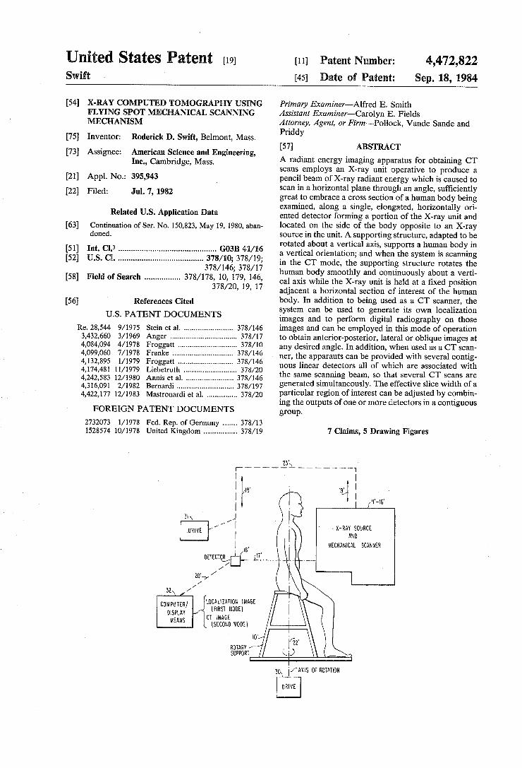
The foregoing objects, advantages, construction and operation of the present invention will become more readily apparent from the following description and accompanying drawings wherein: FIG. 1 is a diagrammatic illustration of a prior art
Medical MICRO-DOSE ® X-ray system; FIG. 2 is a diagrammatic illustration of the radiant
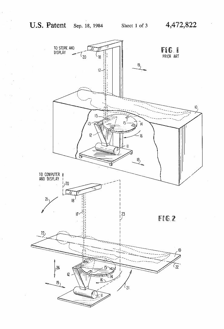
energy imaging apparatus constructed in accordance with one embodiment of the present invention; FIG. 3 illustrates the system of FIG. 2 used as a CT
scanner; FIG. 4 is a diagrammatic illustration of a modi?ed
detector arrangement which can be employed in the arrangement of FIG. 2 to obtain multiple slice scans; FIG. 5 is a diagrammatic illustration of the radiant
energy imaging apparatus constructed in accordance with another embodiment of the present invention.
DESCRIPTION OF THE PREFERRED EMBODIMENTS
As described previously, the present invention is concerned with a radiant energy imaging apparatus for obtaining CT scans and other types of scan for medical and other purposes. It is based on the scanning mecha nism and the single ef?cient detector employed in the Medical MICRO-DOSE ® X-ray system manufactured by American Science and Engineering, Inc., Cam bridge, Mass. That prior system is illustrated in FIG. 1 of the drawings. The apparatus shown in FIG. 1 comprises a table or
support structure 10 adapted to support the body of a patient who is to be examined by means of penetrating radiation, and an associated X-ray system adapted to produce a pencil beam of X-rays which is caused to scan across the patient’s body. The X-ray system corre sponds in general to the system which is shown in Stein et al US. Pat. No. Re. 28,544, the disclosure of which is incorporated herein by reference, and comprises a con ventional rotating anode X-ray tube 11 whose output is
4,472,822 5
collimated into a narrow fan beam by means of a wedge-shaped collimator 12, fabricated for example as a composite of lead and tungsten, having an elongated comparatively narrow opening 13 at its upper end. The fan beam is further collimated by an X-ray opaque chopper wheel 14, fabricated for example of lead-?lled aluminum with tungsten jaws, that is provided with a plurality of slits 15 extending radially inwardly from the outer edge of said wheel 14. The chopper wheel 14 is mounted for rotation about a central axis as indicated by arrow 16, and is so positioned that an edge of the wheel overlies and completely covers slot 13 in collimator 12, except for the region of overlap of the slits 13, 15. For purpose of illustration, i.e., in order that the slot 13 may be more readily seen in FIGS. 1 and 2, this completely overlying relationship has not been shown in said ?g ures, and reference is accordingly made to the drawings in Stein et al US. Pat. Re. 28,544 in this respect. The lead and tungsten employed in collimators 12, 14
fully attenuate X-rays except in the region of overlap of the slits and the motion of the wheel 14 causes the slits 15 to traverse the fan beam repeatedly, thereby generat ing a single scanning pencil beam of X-rays 17 whose cross sectional dimensions are determined by the shapes of slits 13 and 15 in their region of overlap. This pencil X-ray beam is partially attenuated by the subject on support 10, and the unattenuated X-rays are absorbed by an elongated photon detector 18, comprising a single efficient detector of the type described in the aforemen tioned Stein et al patent, as the pencil beam 17 scans from a position adjacent one end of detector 18 toward a position adjacent the other end thereof. During this scanning operation, the entire X-ray system, including the X-ray source, the chopper wheel, and the detector, is moved as a unit in the direction indicated by arrows 19, i.e., in a direction transverse to the direction of elongation of detector 18, along the length of the pa tient, who remains stationary on table 10, to produce multiple rows of data in the nature of a TV raster which data is supplied from detector 18, as at 20. These output signals produce a radiograph on the video (TV) moni tor (not shown) e.g., by intensity modulating the CRT electron beam on a storage oscilloscope, or on a scan converter storage tube of known type. Alternatively, the output signals may be digitized and stored in a com puter accessible memory, and processed by computer to produce a digital radiograph on a video monitor or other display device. The signal detector 18 is a scintillation crystal cou
pled to one or more photomultipliers whose outputs are combined, and nerly 100% of the X-rays which are not attenuated by the patient are detected. The electrical signals obtained at the output of the photomultipliers are pulses, with the amplitude of each pulse being pro portional to the energy of a single detected X-ray pho ton. Since the rate of X-ray photons incident on the detector is large, these pulses add together to give a net signal which, at any instant of time, is proportional to the incident X-ray flux in the attenuated X-ray pencil beam. The electrical signal from the detector, during one scan of the pencil beam from one end of the detec tor to the other, corresponds to a one-dimensional ra diographic line image of the object, analogous to one scan line on an ordinary television monitor. The second dimension of the image is generated by virtue of the motion of the source-collimator-detector plane with respect to the patient. The series of line images is se quentially stored in digital form and, after the X-ray
5
20
25
35
45
55
65
6 exposure is complete, the radiographic data are read out line-by-line onto the television monitor. The readout is ' sequentially ordered in the same manner in which the data are read into storage so that the image on the moni tor screen is the X-ray shadowgraph of the subject being examined.
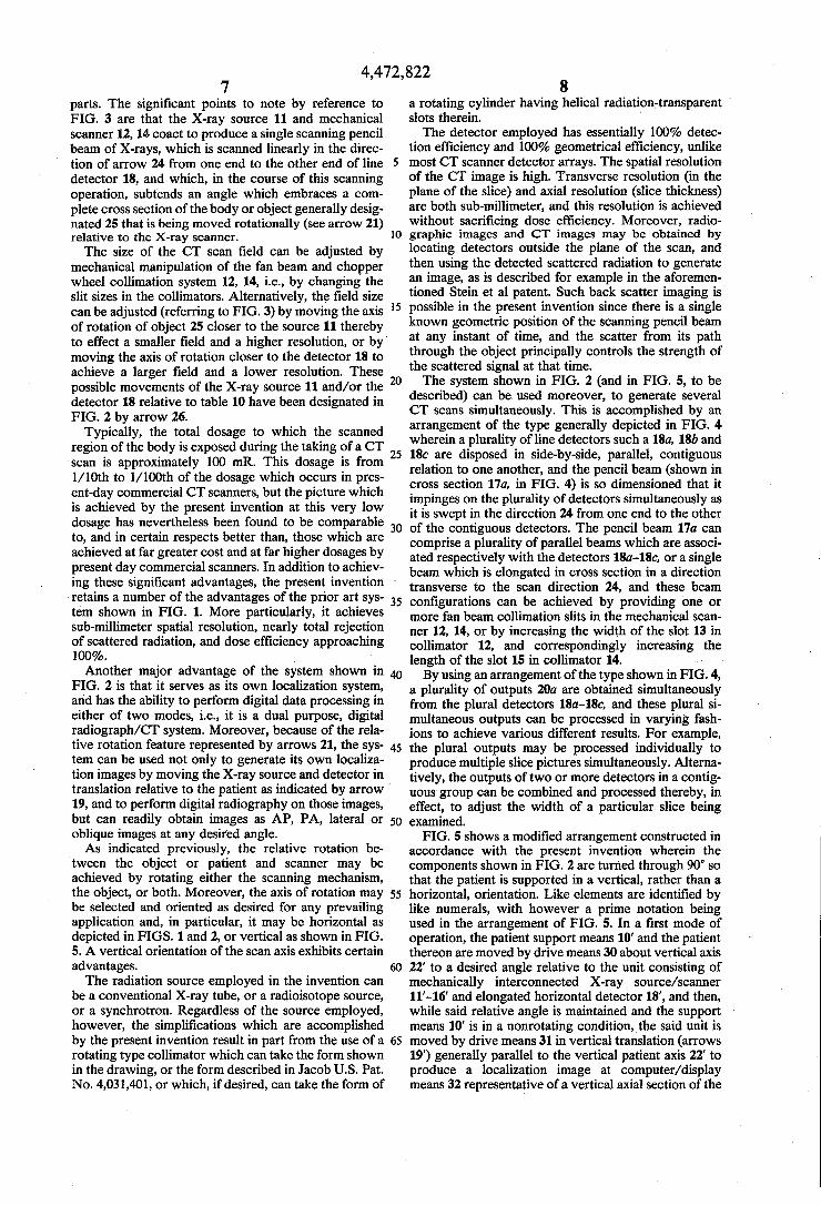
In the prior art apparatus shown in FIG. 1, the X-ray system is adapted to be moved in translation only, i.e., in the direction of arrows 19. However in accordance with the present invention, the X-ray system of FIG. 1, like parts of which are designated by like numerals in FIG. 2, is mounted to exhibit a variety of degrees of motion under the control of various drive means kown per se and therefore not shown in FIG. 2 for purposes of simplicity. The translateral motion indicated by arrow 19 may be retained in FIG. 2 when it is desired to have the system of the present invention exhibit the capabili ties already described in reference to FIG. 1 and/or when the system of FIG. 2 is to provide CT scans pre ceded by the generation of localization images. Basi cally, however, the system of FIG. 2 is characterized by an arrangement wherein the translateral motion indi cated by arrow 19 is replaced by or supplemented by a rotational motion of the patient relative to the scanner, as indicated by arrows 21, about an axis of rotation 22 which is the nominal axis of a patient supported on table 10. In practice, either the patient or the scanning mecha nism, or both, may be rotated. When the scanning mechanism is to be rotated about axis 22, it is rotated as a unit, i.e., line detector 18 on one side of table 10 is physically connected to the X-ray generating mecha nism and collimator structure on the other side of said table, by means of an appropriate interconnecting struc ture which is indicated by broken line 23. When used as a CT scanner, the CT scan achieved by
the system of FIG. 2 is essentially similar to that of so-called two motion, or translate-rotate, CT scanners, but without the usual mechanical disadvantages and complexities of known such devices which require re ciprocating mechanical translations of X-ray source, collimator and detector(s) to take place between incre mental rotational motions of the assembly. In the pres ent invention, the two motions (sweeping beam and rotating scanning assembly) are performed smoothly, continuously and simultaneously. The number of tra verses of the pencil beam during one rotation of the scanner relative to the patient establishes the number of “views” of the CT scan. The data read out from the detector 18 is reconstructed by methods well known in the CT art, e. g., appropriate algorithms are described in the article Fan Beam Reconstruction Methods by B. K. P. Horn, Proceedings IEEE, December 1979, pp. 1616-1623. One traverse of the beam along detector 18 typically
takes approximately l/ 180 seconds, and the typical rotation of the object being examined relative to the X-ray scanning system may be accomplished in approxi mately 5 to 10 seconds, giving a total of between 900 and 1800 views during a complete rotation of the X-ray scanner relative to the patient. These ?gures are given by way of example only, and in one embodiment of the invention the scan occurred at the rate of 30 scans per second, and the complete relative rotation of the scan ning system and object being examined occurred in a time period of 15 seconds, to produce 450 views. The general operation of the system, in accordance with these aspects of ‘the invention, is depicted in FIG. 3 wherein, again, like numerals are used to designate like
4,472,822 7
parts. The signi?cant points to note by reference to FIG. 3 are that the X-ray source 11 and mechanical scanner 12, 14 coact to produce a single scanning pencil beam of X-rays, which is scanned linearly in the direc tion of arrow 24 from one end to the other end of line detector 18, and which, in the course of this scanning operation, subtends an angle which embraces a com plete cross section of the body or object generally desig nated 25 that is being moved rotationally (see arrow 21) relative to the X-ray scanner. The size of the CT scan ?eld can be adjusted by
mechanical manipulation of the fan beam and chopper wheel collimation system 12, 14, i.e., by changing the slit sizes in the collimators. Alternatively, the ?eld size can be adjusted (referring to FIG. 3) by moving the axis of rotation of object 25 closer to the source 11 thereby to effect a smaller ?eld and a higher resolution, or by' moving the axis of rotation closer to the detector 18 to achieve a larger ?eld and a lower resolution. These possible movements of the X-ray source 11 and/or the detector 18 relative to table 10 have been designated in FIG. 2 by arrow 26.
Typically, the total dosage to which the scanned region of the body is exposed during the taking of a CT scan is approximately 100 mR. This dosage is from V 10th to l/ 100th of the dosage which occurs in pres ent-day commercial CT scanners, but the picture which is achieved by the present invention at this very ,low dosage has nevertheless been found to be comparable to, and in certain respects better than, those which are achieved at far greater cost and at far higher dosages by present day commercial scanners. In addition to achiev ing these signi?cant advantages, the present invention ' retains a number of the advantages of the prior art sys tem shown in FIG. 1. More particularly, it achieves sub-millimeter spatial resolution, nearly total rejection of scattered radiation, and dose ef?ciency approaching 100%. Another major advantage of the system shown in
FIG. 2 is that it serves as its own localization system, and has the ability to perform digital data processing in either of two modes, i.e., it is a dual purpose, digital radiograph/CT system. Moreover, because of the rela tive rotation feature represented by arrows 21, the sys tem can be used not only to generate its own localiza tion images by moving the X-ray source and detector in translation relative to the patient as indicated by arrow 19, and to perform digital radiography on those images, but can readily obtain images as AP, PA, lateral or oblique images at any desired angle. As indicated previously, the relative rotation be
tween the object or patient and scanner may be achieved by rotating either the scanning mechanism, the object, or both. Moreover, the axis of rotation may be selected and oriented as desired for any prevailing application and, in particular, it may be horizontal as depicted in FIGS. 1 and 2, or vertical as shown in FIG. 5. A vertical orientation of the scan axis exhibits certain advantages. The radiation source employed in the invention can
be a conventional X-ray tube, or a radioisotope source, or a synchrotron. Regardless of the source employed, however, the simpli?cations which are accomplished by the present invention result in part from the use of a rotating type collimator which can take the form shown in the drawing, or the form described in Jacob US. Pat. No. 4,031,401, or which, if desired, can take the form of
40
55
60
8 a rotating cylinder having helical radiation-transparent ' slots therein. The detector employed has essentially 100% detec
tion efficiency and 100% geometrical ef?ciency, unlike most CT scanner detector arrays. The spatial resolution of the CT image is high. Transverse resolution (in the plane of the slice) and axial resolution (slice thickness) are both sub-millimeter, and this resolution is achieved without sacri?cing dose ef?ciency. Moreover, radio graphic images and CT images may be obtained by locating detectors outside the plane of the scan, and then using the detected scattered radiation to generate an image, as is described for example in the aforemen tioned Stein et a] patent. Such back scatter imaging is possible in the present invention since there is a single known geometric position of the scanning pencil beam at any instant of time, and the scatter from its path through the object principally controls the strength of the scattered signal at that time. The system shown in FIG. 2 (and in FIG. 5, to be
described) can be used moreover, to generate several CT scans simultaneously. This is accomplished by an arrangement of the type generally depicted in FIG. 4 wherein a plurality of line detectors such a 18a, 18b and 18c are disposed in side-by-side, parallel, contiguous relation to one another, and the pencil beam (shown in cross section 17a, in FIG. 4) is so dimensioned that it impinges on the plurality of detectors simultaneously as it is swept in the direction 24 from one end to the other of the contiguous detectors. The pencil beam 17a can comprise a plurality of parallel beams which are associ ated respectively with the detectors 180-180, or a single beam which is elongated in cross section in a direction transverse to the scan direction 24, and these beam con?gurations can be achieved by providing one or more fan beam collimation slits in the mechanical scan ner 12, 14, or by increasing the width of the slot 13 in collimator 12, and correspondingly increasing the length of the slot 15 in collimator 14. By using an arrangement of the type shown in FIG. 4,
a plurality of outputs 20a are obtained simultaneously from the plural detectors 180-180, and these plural si multaneous outputs can be processed in varying fash ions to achieve various different results. For example, the plural outputs may be processed individually to produce multiple slice pictures simultaneously. Alterna tively, the outputs of two or more detectors in a contig uous group can be combined and processed thereby, in effect, to adjust the width of a particular slice being examined.
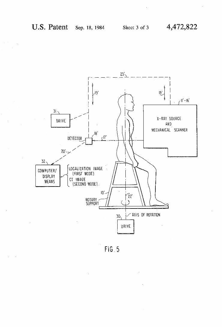
FIG. 5 shows a modi?ed arrangement constructed in accordance with the present invention wherein the components shown in FIG. 2 are turned through 90° so that the patient is supported in a vertical, rather than a horizontal, orientation. Like elements are identi?ed by like numerals, with however a prime notation being used in the arrangement of FIG. 5. In a ?rst mode of operation, the patient support means 10’ and the patient thereon are moved by drive means 30 about vertical axis 22' to a desired angle relative to the unit consisting of mechanically interconnected X-ray source/scanner 11'-16’ and elongated horizontal detector 18’, and then, while said relative angle is maintained and the support means 10’ is in a nonrotating condition,_the said unit is moved by drive means 31 in vertical translation (arrows 19') generally parallel to the vertical patient axis 22’ to produce a localization image at computer/display means 32 representative of a vertical axial section of the
4,472,822 patient. Then, in a second mode of operation, the unit 11’—16', 18' is positioned translationally by drive means 31 adjacent a particular corss-sectional portion of inter est of the patient being examined, selected by reference to said localization image, whereafter the support 10' and the patient thereon are rotated smoothly and con tinuously by drive means 30 about the vertically ori ented axis of rotation 22' while the unit l1'—16’, 18’ is held stationary thereby to produce, by means of com puter/ display means 32, a CT image representative of a horizontal slice of the patient. The present invention lends itself to other techniques
as well. For example, by using different ?ltering or detector characteristics for contiguous planes, or by using a low energy detector backed up by a high energy detector in the same plane, dual energy data may be obtained simultaneously. This may be used for either CT or digital radiographic images. The subtraction of two images taken with different energy responses can be used to emphasize iodinated contrast material. Utiliz ing this feature combined with multiple slices allows an image of, for example, blood vessels in a volume rather than a slice. While I have thus described preferred embodiments
of the present invention, it must be understood that the foregoing description is intended to be illustrative only and not limitative of the present invention. Many varia tions have already been described, and others will be apparent to those skilled in the art. For example, al though the implementation of the invention has been described in connection with medical diagnostic imag ing, the invention is also applicable to any nondestruc tive testing application. All such variations and modi? cations are intended to fall within the scope of the ap pended claims. Having thus described my invention, I claim: 1. A radiant energy imaging apparatus for examining
a human body by means of penetrating radiation, said apparatus comprising support means for supporting a human body to be examined and for rotating the human body about a vertically oriented axis of rotation, an X-ray system movable translationally as a unit in a verti cal direction parallel to said axis of rotation; said X-ray system comprising a source of X-rays located entirely on one side of said support means, elongated radiant energy detector means located on the opposite side of said support means and extending in a horizontal direc tion transverse to said vertical axis of rotation, and a mechanical scanning device located entirely between said X-ray source and said support means for producing a single pencil beam of X-rays and for scanning said single pencil beam in a horizontal plane through a human body on said support means and along the hori zontal direction of elongation of said detector; means the length of said elongated detector means and the positions of said detector means and mechanical scan ning device being selected to cause said pencil beam of X-rays to subtend an angle which embraces a complete cross section of a human body on said support means as said pencil beam of X-rays is scanned horizontally along said detector means; drive means for selectively rotat ing said support means about its vertical axis of rotation and for selectively effecting vertical translational move ment of said X-ray source, said mechanical scanning device and said detector means as a unit in a direction parallel to said vertical axis of rotation and relative to a human body to be examined; and means responsive to the signals which are produced by said elongated hori
25
35
40
45
55
60
10 zontal detector means as it is scanned by said pencil beam for generating images of the vertically oriented human body being examined on said support means; said drive means including means operative in a ?rst mode to dispose said unit at a desired angle relative to said support means and to move said unit in translation generally parallel to the elongated vertical axis of rota tion of said support means while said unit is maintained at said angle relative to said support means and while said support means is in a nlonrotating condition, thereby to produce a localization image representative of a vertical axial section of the human body being examined, and said drive means including means opera: tive in a second mode to position said unit translation ally relative to said support means to a predetermined position adjacent a particular cross-sectional portion of interest of the human body being examined, selected by reference to said localization image, and to rotate said support means and the human body thereon smoothly and continuously about said vertically oriented axis of rotation while said unit is held stationary at said prede termined position thereby to produce in said second mode of operation an image representative of a horizon tal slice of the human body being examined at the cross sectional portion of interest selected by reference to the localization image produced during said ?rst mode of operation.
2. The radiant energy imaging apparatus to claim 1 wherein said X-ray system is operative to expose said body to a total X-ray dosage of substantially 100 mR during a complete rotation of said body to be examined.
3. The radiant energy imaging apparatus of claim 1 wherein a plurality of elongated detectors are disposed horizontally in side-by-side parallel relation to one an other, said pencil beam of X-rays impinging on said plurality of detectors simultaneously, whereby said plurality of detectors simultaneously produce output signals representative respectively of the X-ray re sponse of adjacent cross-sectional slices of the body to be examined as said drive means rotates said human body about said vertically oriented axis of rotation.
4. The radiant energy imaging apparatus of claim 3 wherein said pencil beam of X-rays has a cross section which is elongated in a direction transverse to the direc tions of elongation of said side~by-side detectors, said pencil beam being scanned respectively from a position adjacent ?rst corresponding ends of said elongated detectors to a position adjacent the opposite corre sponding ends of said elongated detectors along a scan path which is transverse to the direction of elongation of said beam.
5. The radiant energy imaging apparatus of claim 3 wherein at least some of said elongated detectors are contiguous with one another, and means for combining the output signals produced by at least two contiguous ones of said detectors for adjusting the width of the cross-sectional slice which is being examined in said body.
6. The method of examining a human body by means of penetrating radiation, comprising the steps of sup porting a human body to be examined along a vertically oriented axis, moving an X-ray unit translationally as a unit in a vertical direction parallel to said axis while said human body is held stationary along said vertically oriented axis, said X-ray unit comprising a source of X-rays located on one side of said axis and a single elongated radiant energy detector oriented horizontally and located on the other side of said axis, said detector