x-ray diffraction measurements for …yadda.icm.edu.pl/yadda/element/bwmeta1.element... ·...
TRANSCRIPT

Fatigue of Aircraft Structures Vol. 1 (2012) 17-28 10.2478/v10164-012-0053-6
X-RAY DIFFRACTION MEASUREMENTS FOR RIVETED JOINTS. THE APPLICATION OF A NOVEL METHODOLOGY
Elżbieta Gadalińska
Jerzy Kaniowski
Institute of Aviation, Warsaw, Poland
Abstract The X-ray diffraction method is the best, widely available, non-destructive measurement
method used to determine the residual and load stresses in crystalline materials. This method can be applied without any limitations to flat specimens. Depending on the equipment geometry, the type of material and geometry of the specimen, there are many limitations, restrictions and recommendations which have to be fulfilled to obtain reliable results. This was the reason for working out a methodology for X-ray diffraction stress measurements for riveted specimens.
The first case to analyze is the necessity of choosing an X-ray tube suitable for the specimen material which will give the diffraction peaks in the range of 2Θ angles between 120° and 180°. Afterwards it is crucial to make the best selection of Bragg’s angle 2Θ. In the vast majority of cases the best selection is the possibly biggest 2Θ angle because of the best accuracy of the measurement. However, for example for aluminum alloys (for KCr
radiation), this choice is not
so obvious. It is much more convenient to perform measurements not for the highest diffraction angle. The best selection in this case is 2Θ=139,3°, and not 156,7°. Other selections which are necessary to be made before measurements are the collimator diameter, time of exposure, tilts and φ oscillations. The proper selection of these parameters is crucial for the fast and efficient performing of measurements and for obtaining reliable results.
Before performing the measurement, especially in the case of the specimen with complicated geometry (for example in the case of riveted specimens made of aluminum alloys), it is necessary to analyze the results obtained paying special attention to the possibility of the appearing of the rivet head/driven rivet head shadow during the measurement. The work describes differences between the X-ray stress measurement results obtained without any interference and the results received after eliminating the selected diffraction peaks for which the shadow of rivet head/driven rivet head has appeared. 1. THEORETICAL BASES OF THE MEASUREMENT
The X-ray diffraction method is the only non-destructive method used for stress measurements.
It enables measurement of absolute stress values. The phenomenon of the X-ray diffraction is based on the interference of diffracted X radiation
on the nodes of crystallographic lattice. The X radiation is a type of electromagnetic radiation whose wavelengths are between 125 10 m and 810 .m The X radiation is a result of collision of accelerated electrons with a metal target, the anode of the X-ray tube. The X-ray diffraction was originally observed by Max von Laue in 1912. Assuming that the X radiation is a type of the electromagnetic wave whose wavelength is of the same order as that of the interplanar spacing,
Brought to you by | Politechnika Swietokrzyska - Kielce University of TechnologyAuthenticated
Download Date | 3/29/16 12:40 PM
Elżbieta Gadalińska, Jerzy Kaniowski
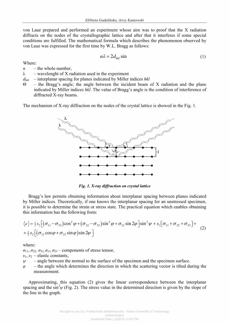
von Laue prepared and performed an experiment whose aim was to proof that the X radiation diffracts on the nodes of the crystallographic lattice and after that it interferes if some special conditions are fulfilled. The mathematical formula which describes the phenomenon observed by von Laue was expressed for the first time by W.L. Bragg as follows:
2 sinhkln d (1) Where: n – the whole number, λ – wavelenght of X radiation used in the experiment dhkl – interplanar spacing for planes indicated by Miller indices hkl Θ – the Bragg’s angle; the angle between the incident beam of X radiation and the plane
indicated by Miller indices hkl. The value of Bragg’s angle is the condition of interference of diffracted X-ray beams.
The mechanism of X-ray diffraction on the nodes of the crystal lattice is showed in the Fig. 1.
Fig. 1. X-ray diffraction on crystal lattice
Bragg’s law permits obtaining information about interplanar spacing between planes indicated
by Miller indices. Theoretically, if one knows the interplanar spacing for an unstressed specimen, it is possible to determine the strain or stress state. The practical equation which enables obtaining this information has the following form:
122
2 2 211 33 22 33 12 1 11 22 33
12 13 232
cos sin sin 2 sin
cos sin sin 2
s s
s
(2)
where: σ11, σ22, σ33, σ13, σ23 – components of stress tensor, s1, s2 – elastic constants, ψ – angle between the normal to the surface of the specimen and the specimen surface. φ – the angle which determines the direction in which the scattering vector is tilted during the
measurement.
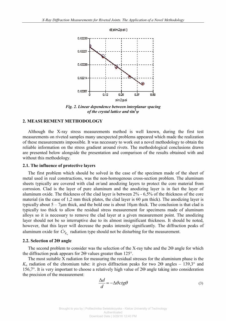
Approximating, this equation (2) gives the linear correspondence between the interplanar spacing and the sin2ψ (Fig. 2). The stress value in the determined direction is given by the slope of the line in the graph.
Brought to you by | Politechnika Swietokrzyska - Kielce University of TechnologyAuthenticated
Download Date | 3/29/16 12:40 PM
X-Ray Diffraction Measurements for Riveted Joints. The Application of a Novel Methodology
Fig. 2. Linear dependence between interplanar spacing
of the crystal lattice and sin2ψ
2. MEASUREMENT METHODOLOGY
Although the X-ray stress measurements method is well known, during the first test measurements on riveted samples many unexpected problems appeared which made the realization of these measurements impossible. It was necessary to work out a novel methodology to obtain the reliable information on the stress gradient around rivets. The methodological conclusions drawn are presented below alongside the presentation and comparison of the results obtained with and without this methodology. 2.1. The influence of protective layers
The first problem which should be solved in the case of the specimen made of the sheet of metal used in real constructions, was the non-homogenous cross-section problem. The aluminum sheets typically are covered with clad or/and anodizing layers to protect the core material from corrosion. Clad is the layer of pure aluminum and the anodizing layer is in fact the layer of aluminum oxide. The thickness of the clad layer is between 2% - 6,5% of the thickness of the core material (in the case of 1,2 mm thick plates, the clad layer is 60 µm thick). The anodizing layer is typically about 5 – 7µm thick, and the bold one is about 10µm thick. The conclusion is that clad is typically too thick to allow the residual stress measurement for specimens made of aluminum alloys so it is necessary to remove the clad layer at a given measurement point. The anodizing layer should not be so interruptive due to its almost insignificant thickness. It should be noted, however, that this layer will decrease the peaks intensity significantly. The diffraction peaks of aluminum oxide for KCr
radiation type should not be disturbing for the measurement.
2.2. Selection of 2Θ angle The second problem to consider was the selection of the X-ray tube and the 2Θ angle for which
the diffraction peak appears for 2Θ values greater than 125°. The most suitable X radiation for measuring the residual stresses for the aluminium phase is the
Kα radiation of the chromium tube: it gives diffraction peaks for two 2Θ angles – 139,3° and 156,7°. It is very important to choose a relatively high value of 2Θ angle taking into consideration the precision of the measurement:
d ctgd
(3)
Brought to you by | Politechnika Swietokrzyska - Kielce University of TechnologyAuthenticated
Download Date | 3/29/16 12:40 PM
Elżbieta Gadalińska, Jerzy Kaniowski
According to the above equation, at low 2Θ angles the value of ∆d is too small to be measured. At high 2Θ angles small changes in the lattice distances give measurable changes in 2Θ. Generally, the highest diffraction angle value should be selected between 2Θ value 125° and the 2Θ limit of the diffractometer.
As mentioned above, there are two diffraction peaks for KCr
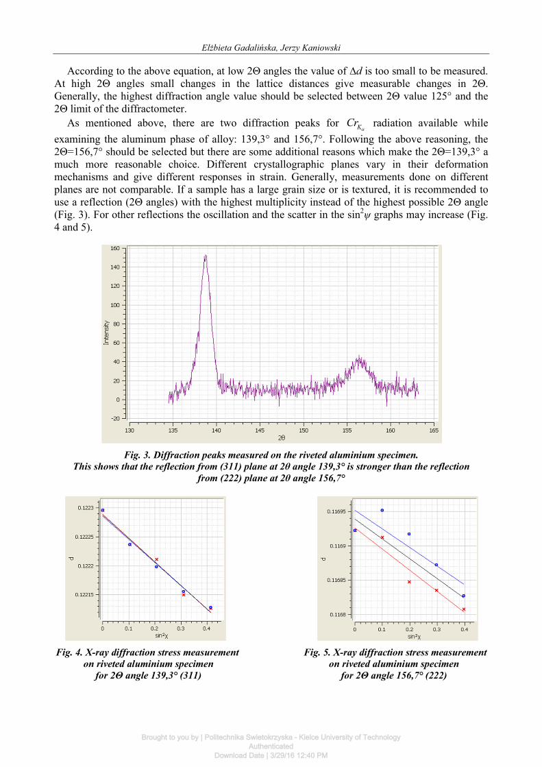
radiation available while examining the aluminum phase of alloy: 139,3° and 156,7°. Following the above reasoning, the 2Θ=156,7° should be selected but there are some additional reasons which make the 2Θ=139,3° a much more reasonable choice. Different crystallographic planes vary in their deformation mechanisms and give different responses in strain. Generally, measurements done on different planes are not comparable. If a sample has a large grain size or is textured, it is recommended to use a reflection (2Θ angles) with the highest multiplicity instead of the highest possible 2Θ angle (Fig. 3). For other reflections the oscillation and the scatter in the sin2ψ graphs may increase (Fig. 4 and 5).
Fig. 3. Diffraction peaks measured on the riveted aluminium specimen.
This shows that the reflection from (311) plane at 2θ angle 139,3° is stronger than the reflection from (222) plane at 2θ angle 156,7°
Fig. 4. X-ray diffraction stress measurement Fig. 5. X-ray diffraction stress measurement
on riveted aluminium specimen on riveted aluminium specimen for 2Θ angle 139,3° (311) for 2Θ angle 156,7° (222)
Brought to you by | Politechnika Swietokrzyska - Kielce University of TechnologyAuthenticated
Download Date | 3/29/16 12:40 PM
X-Ray Diffraction Measurements for Riveted Joints. The Application of a Novel Methodology
2.3. Selection of collimator diameter The main aim of our research was to obtain as much information as possible on the stress
distribution and its gradient around the rivet. The finite element method applied to this issue shows very large stress gradients both in the case of radial and tangential stresses [1, 2]. This necessitates the application of collimators of very small diameters: 0,5 or 0,6mm. 2.4. Selection of time of exposure
The measurement of the stress gradient in aluminium alloys samples requires using collimators of very small diameters as it was indicated above. The time of exposure needed to obtain well-defined peaks is inversely proportional to the square of the collimator diameter. It is recommended to determine the optimal exposure time using increasing exposure time until no more improvements are obtained in the results. In the case of a textured sample or/and sample with a large grain size it would be helpful to use optimized φ and ψ oscillation options.
Additionally, to shorten the time of exposure the full power of the X-ray tube may be used, meaning voltage and current intensity of 30kV and 9mA respectively. Another option is the exploitation of the long detectors instead of short ones. This option will reduce the exposure time by about 30%. It was observed that the smallest collimator of 0,5mm diameter did not give any reasonable results with short detectors. Only the exploitation of long detectors enables obtaining results for this collimator diameter.
The new Xtronic software used with the diffractometer makes it possible to introduce changes in the process of the measurement – the subtraction of the dark current can be done only once at the beginning of each measurement direction, which reduces exposure time by about 50%. 2.5. Selection of ψ tilts and φ oscillations
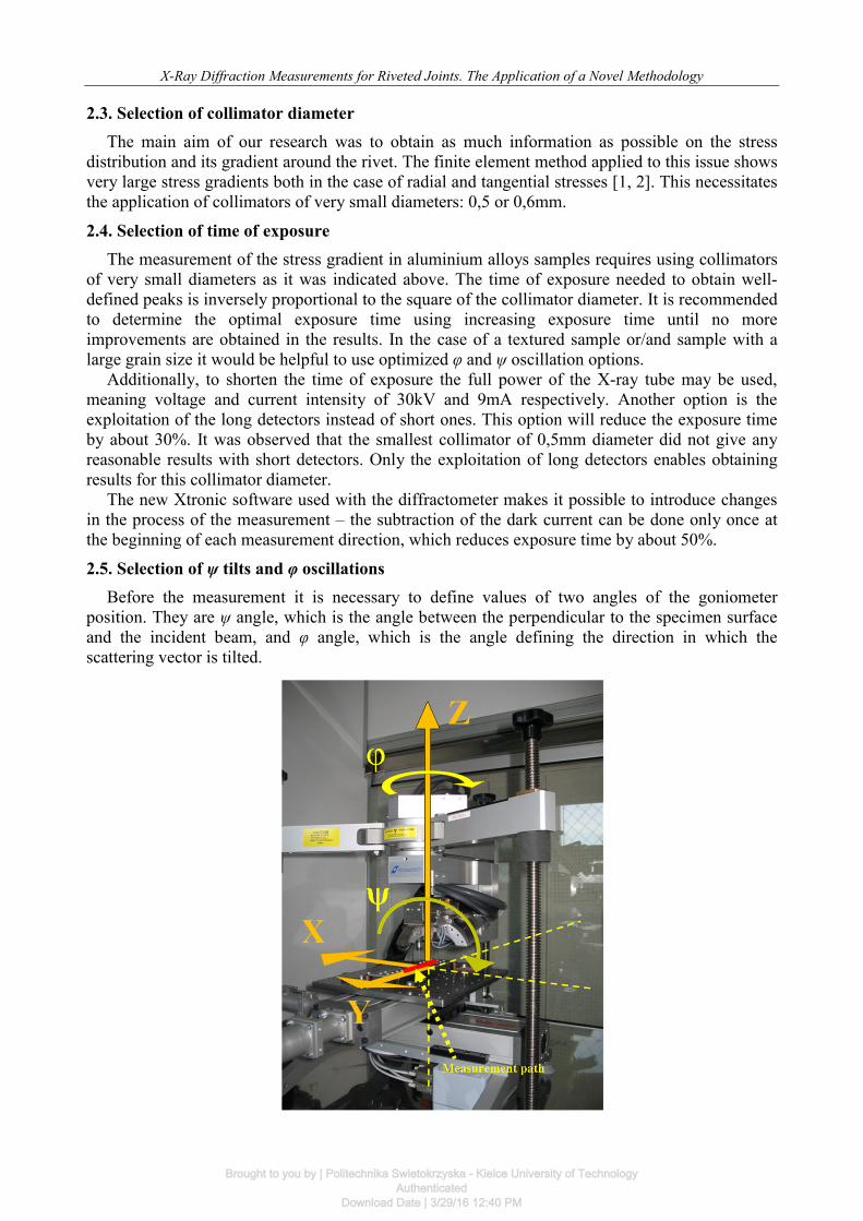
Before the measurement it is necessary to define values of two angles of the goniometer position. They are ψ angle, which is the angle between the perpendicular to the specimen surface and the incident beam, and φ angle, which is the angle defining the direction in which the scattering vector is tilted.
Brought to you by | Politechnika Swietokrzyska - Kielce University of TechnologyAuthenticated
Download Date | 3/29/16 12:40 PM
Elżbieta Gadalińska, Jerzy Kaniowski
The minimum number of tilt angles (ψ) during the measurement of the stress gradient is 4 on both negative and positive side, using tilt angles between 0°– 45°. It is reasonable to increase the tilt number and application of tilt angle oscillation in the case of textured samples – it might improve the stress results.
Oscillation of the φ angle might improve stress results when textured and large grain sized samples are involved. Oscillations up to ±5° can be made without significantly affecting the accuracy of the stress in terms of measurement direction. It is not recommended to use oscillation higher than ±10°. Increasing the number of the oscillation steps will improve the measurement and will also increase the total exposure time. 2.6. Location of measurement points
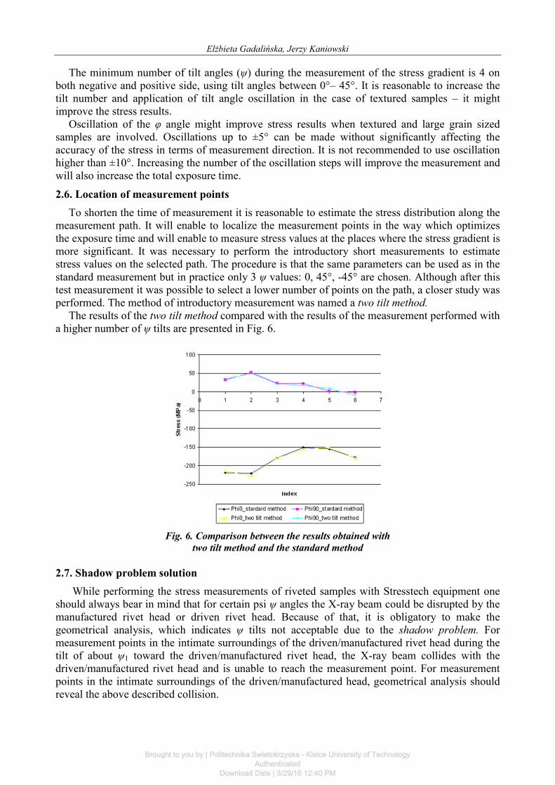
To shorten the time of measurement it is reasonable to estimate the stress distribution along the measurement path. It will enable to localize the measurement points in the way which optimizes the exposure time and will enable to measure stress values at the places where the stress gradient is more significant. It was necessary to perform the introductory short measurements to estimate stress values on the selected path. The procedure is that the same parameters can be used as in the standard measurement but in practice only 3 ψ values: 0, 45°, -45° are chosen. Although after this test measurement it was possible to select a lower number of points on the path, a closer study was performed. The method of introductory measurement was named a two tilt method.
The results of the two tilt method compared with the results of the measurement performed with a higher number of ψ tilts are presented in Fig. 6.
Fig. 6. Comparison between the results obtained with
two tilt method and the standard method 2.7. Shadow problem solution
While performing the stress measurements of riveted samples with Stresstech equipment one should always bear in mind that for certain psi ψ angles the X-ray beam could be disrupted by the manufactured rivet head or driven rivet head. Because of that, it is obligatory to make the geometrical analysis, which indicates ψ tilts not acceptable due to the shadow problem. For measurement points in the intimate surroundings of the driven/manufactured rivet head during the tilt of about ψ1 toward the driven/manufactured rivet head, the X-ray beam collides with the driven/manufactured rivet head and is unable to reach the measurement point. For measurement points in the intimate surroundings of the driven/manufactured head, geometrical analysis should reveal the above described collision.
Brought to you by | Politechnika Swietokrzyska - Kielce University of TechnologyAuthenticated
Download Date | 3/29/16 12:40 PM

X-Ray Diffraction Measurements for Riveted Joints. The Application of a Novel Methodology
Mathematical relationship for boundary ψ value for the manufactured rivet head and driven rivet head respectively are presented below (eq. 4 and 5):
2 211
1 221802 2
90 arcsinkd
h HX
h Ratg
X H
(4)
Where: h1 – manufactured rivet head height R1 – manufactured rivet head diameter dk – inner collimator diameter X – distance between the collimator axis and the rivet axis H – difference between the manufactured rivet head radius and its height
Brought to you by | Politechnika Swietokrzyska - Kielce University of TechnologyAuthenticated
Download Date | 3/29/16 12:40 PM

Elżbieta Gadalińska, Jerzy Kaniowski
2 22arcsin kdX
h X harctg
(5)
Where: X – distance between the collimator axis and the manufactured head brink h – formed rivet head height dk – inner collimator diameter
The second, analogical problem for detectors is the driven/manufactured head shadow. Sometimes during tangential stresses measurements one detector may be shadowed by the driven/manufactured head. It is very important to analyse measurement results before stress calculations to determine if the detector covering occurred.
Another problem one needs to be aware of is the possibility of collision between the collimator and the driven/manufactured rivet head. It is crucial to determine the collision possibility before the measurement – otherwise the collision can result in the collimator’s damage, which will disrupt any measurement for a few weeks.
Fig. 7. Explanation of the driven rivet Fig. 8. Explanation of the manufactured rivet
head shadow problem during X-ray stress head shadow problem during X-ray stress measurement with Xstress3000 equipment measurement with Xstress3000 equipment
h
dk/2
Ψ
gsk
d
D
Ψ
dk
dk ψ/2
x2
x1
xk
X
CD
A EF
B G
Brought to you by | Politechnika Swietokrzyska - Kielce University of TechnologyAuthenticated
Download Date | 3/29/16 12:40 PM

X-Ray Diffraction Measurements for Riveted Joints. The Application of a Novel Methodology
For a calibrated distance from specimen d at measurement points in the intimate surroundings of the driven/manufactured rivet head during the tilt of about ψ1 (psi 1) toward the driven/manufactured rivet head, the collimator could touch the driven head/manufactured rivet head (fig. no. 7 and 8). 3. THE APPLICATION OF THE NOVEL METHODOLOGY 3.1. The specimen, measurement paths and parameters
The novel methodology described above was applied to the aluminum specimen presented in Fig. 9. The specimen during the measurement is presented in Fig. 10. The specimen was marked with No-4A-31 symbol.
Fig. 9. The No-4A-31 specimen
Fig. 10. The No-4A-31 specimen during the X-ray stress measurement
The material of the specimen was 2024-T3 alloy and the material of rivets was PA25 alloy.
The specimen represents the riveted strap joint. Measurements were performed on both sides of the specimen along two paths: on the side of the manufactured rivet head (stress values were determined in radial direction only) and on the side of the driven rivet head (both, radial and
2L
H
L1
23
t 1 2 2
g
Brought to you by | Politechnika Swietokrzyska - Kielce University of TechnologyAuthenticated
Download Date | 3/29/16 12:40 PM

Elżbieta Gadalińska, Jerzy Kaniowski
tangential stresses values were obtained). In the case of the path between the rivets it was very important to take into account the manufactured/driven rivet head from both rivets simultaneously. Measurement paths were drawn on the specimen as it can be seen in Fig. 10. For each side of the specimen there were exploited measurement parameters as presented in the tab. 1.
Table 1. Measurement parameters.
1depending on the solution to the manufactured/driver rivet head shadow problem The measurements results are presented below in graphs 1 – 6. 3.2. Measurement results – the manufactured rivet head
Graph 1. Rivets no. 1 and 2, radial direction. Comparison results obtained
before and after rivet head shadow analysis
Brought to you by | Politechnika Swietokrzyska - Kielce University of TechnologyAuthenticated
Download Date | 3/29/16 12:40 PM
X-Ray Diffraction Measurements for Riveted Joints. The Application of a Novel Methodology
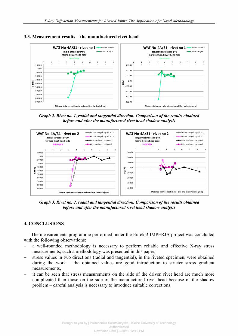
3.3. Measurement results – the manufactured rivet head
Graph 2. Rivet no. 1, radial and tangential direction. Comparison of the results obtained
before and after the manufactured rivet head shadow analysis
Graph 3. Rivet no. 2, radial and tangential direction. Comparison of the results obtained
before and after the manufactured rivet head shadow analysis
4. CONCLUSIONS
The measurements programme performed under the Eureka! IMPERJA project was concluded with the following observations: a well-rounded methodology is necessary to perform reliable and effective X-ray stress
measurements; such a methodology was presented in this paper, stress values in two directions (radial and tangential), in the riveted specimen, were obtained
during the work – the obtained values are good introduction to stricter stress gradient measurements,
it can be seen that stress measurements on the side of the driven rivet head are much more complicated than those on the side of the manufactured rivet head because of the shadow problem – careful analysis is necessary to introduce suitable corrections.
Brought to you by | Politechnika Swietokrzyska - Kielce University of TechnologyAuthenticated
Download Date | 3/29/16 12:40 PM

Elżbieta Gadalińska, Jerzy Kaniowski
REFERENCES [1] Kaniowski J. (2010). Improving the Fatigue Performance of Riveted Joints in Airframes.
Warsaw: Institute of Aviation. (research project report Nr EUREKA/59/2006). [2] Müller R.P.G. (1995) An experimental an Analytical Investigation on the Fatigue Behaviour
of Fuselage Riveted Lap Joints, Ph. D. Thesis, Delft University of Technology, The Netherlands, Delft.
[3] Kaniowski J., Korzeniewski B., Hakanen M. (2011). Methodology of residual stress measurements for rivet joints, Fatigue of Aircraft Structures, Vol. 1 (2011) 42-52, DOI: 10.2478/v10164-010-0036-4
Brought to you by | Politechnika Swietokrzyska - Kielce University of TechnologyAuthenticated
Download Date | 3/29/16 12:40 PM