x-ray tube model number 2208208 model description mx75t
TRANSCRIPT

GE Medical Systems MX75TH.11/ RADPLUS 2100Rev 9 DTP 2236721-100
Technical PublicationsRev 9
RADPLUS 2100 X-Ray tube unitModel number 2185226Model description MX75TH.11
Consisting of :
X-Ray tubeModel number 2208208Model description MX75T.1&X-Ray tube housingModel number 2222709Model description MX75H.1
GE Medical Systems______________________________________________________________________________________________________________
Copyright” 1999, by General Electric Co. Do not duplicate
GE Medical Systems MX75TH.11/ RADPLUS 2100Rev 9 DTP 2236721-100
i
WARNING
X-Ray equipment is dangerous to both patient and operator unless measures ofprotection are strictly observed
Though this equipment is built to the highest standards of electrical and mechanicalsafety, the useful X-Ray beam becomes a source of danger in the hands of theunauthorized or unqualified operator. Excessive exposure to X-Ray Radiation causesdamage to human tissue.
Therefore, adequate precautions must be taken to prevent unauthorized or unqualifiedpersons from operating the equipment or exposing themselves or others to itsradiation. Do not operate the tube excepted in accordance with Information included inpresent technical documentation.
Before operation, person qualified and authorized to operate this equipment should befamiliar with the Recommendations of the International Commission on RadiologicalProtection, contained in Annals Number 26 of the ICRP, and with applicable nationalstandards.
CHAPTER 0 - REGULATORY REQUIREMENTS
This equipment generates, uses, and can radiate radio frequency energy,. Theequipment may cause radio frequency interference to other medical or non medicaldevices and radio communications. To provide reasonable protection against suchinterference, this product complies with emission limits for group 1 Class B MedicalDevices as stated in EN 60601-1-2
However there is no guarantee that interference will not occur in a particularinstallation. If this equipment is found to cause interference (which may be determinedby switching the equipment on and off), the user (or qualified service personnel)should attempt to correct the problem using on or more of the following measures :• Reorientate or relocate the affected device(s)
• Increase the separating space between the equipment and the affected device
• Power the equipment from a source different from that of the affected deviceConsult the point of purchase or the service representative for further suggestions.The manufacturer is not responsible for any interference caused either by the use ofthe interconnect cables other than those recommended or by unauthorized changes ormodifications to this equipment. Unauthorized changes or modifications could void theusers’ authority to operate the equipment.
To comply with the regulations applicable to an electromagnetic interface for a Group 1class A Medical device, all interconnect cables to peripheral devices must be shieldedand properly grounded . Among other, to achieve correct electromagnetic compatibility,the braid of the stator power cable must be connected to the ground of the tubehousing. Use of cables not properly shielded or grounded may result in the equipmentcausing radio frequency interference in violation of the European Union Medical Devicedirective and FCC regulations
GE Medical Systems MX75TH.11/ RADPLUS 2100Rev 9 DTP 2236721-100
ii
This product complies with the regulatory requirements of the following :
• Council Directive 93/42/EEC concerning medical devices when it bears the followingCE marking of conformity :
CE 0459European registered place of businessGE Medical System EuropeQuality Assurance ManagerBP 34F 78533 BUC CEDEXFranceTel : + 33 1 30 70 40 40
• Green QSD Standard issued by MDA (Medical Device Agency, Department ofHealth, UK)
• Medical Device Good Manufacturing Practice Manual issued by FDA (Food and DrugAdministration, Department of Health USA)
• International Electrotechnical Commission (IEC), Canadian Standards Association(CSA), and Underwriters Laboratories, Inc. (UL) Safety standards, whenapplicable.
• Japan standard MHW
WARNING
CE marking on X-Ray tube assembly concerns only the X-ray tube assembly alone
This X-Ray tube assembly is intended to be used in a medical system which can be CEmarked system or a non CE marked system.
Refer to accompanying document of the system for compatibility of the X-Ray tubeassembly and for information concerning CE marking of the system.
To sum up, installing a CE marked X-Ray tube assembly in a non CE marked systemdoes not make the whole system CE marked
Accompanying document of this product according to IEC 601-2-28/1993This document must be transmitted to the user and assembler of the X-Ray assembly.Original languages of editing : English.
Specifications to change without notices.
General Electric Medical Systems is ISO 9001 certified company
GE Medical Systems MX75TH.11/ RADPLUS 2100Rev 9 DTP 2236721-100
iii
TABLE OF CONTENTS
Chapter Description Page
CHAPTER 0 - REGULATORY REQUIREMENTS........................................................................... i
TABLE OF CONTENTS......................................................................................... iiiREVISION HISTORY.............................................................................................iv
CHAPTER 1 - GENERAL ..........................................................................................................1-1
CHAPTER 2 - XRAY TUBE MX75T.1.......................................................................................2-1
Section 1 - X-Ray Tube MX75T.1 specifications .................................................2-1
Section 2 - Ratings/Charts..................................................................................2-22-1 Single load ratings.......................................................................2-22-2 Electron emission curves. ............................................................2-32-3 Anode cooling and heating curves. .............................................2-4
CHAPTER 3 - X-RAY TUBE ASSEMBLY MX 75 TH11 SPECIFICATIONS .............................3-1
Section 1 - Description .......................................................................................3-11-1 Tube housing / Tube configuration..............................................3-11-2 Construction................................................................................3-1
Section 2 - XRay Tube Assembly MX75TH.11 specifications ..............................3-22-1 MX75TH.11 Characteristics..........................................................3-22-2 Housing outline drawing ..............................................................3-32-3 Marking .......................................................................................3-32-4 Electrical characteristics...............................................................3-4
2-4-1 General ...............................................................................3-42-4-2 Electrical connection............................................................3-4
2-5 Thermal characteristics and temperature safety devices..............3-52-6 Casing cooling and heating curves..............................................3-6
Section 3 - Patient, user, assembler and installator safety..................................3-73-1 Radiation protection ....................................................................3-73-2 Electrical protection : ...................................................................3-7
Section 4 - Installation and maintenance instructions : .......................................3-84-1 Installation instructions : ..............................................................3-84-2 Preventive maintenance instructions:...........................................3-9
Section 5 - Environmental health & safety (EHS) information............................3-10
Section 6 - Tube unit catalog number :.............................................................3-10
Section 7 - Warranty :.......................................................................................3-10
CHAPTER 4 - RENEWAL PARTS................................................................... 4-1/4-2/4-3/4-4/4-5
GE Medical Systems MX75TH.11/ RADPLUS 2100Rev 9 DTP 2236721-100
iv
REVISION HISTORY
REV DATE TYPE OF MODIFICATION
0 28 - Dec - 98 Initial release.
1 20 - Jan - 99 Update.
2 15 - Fev - 99 Update.
3 01 - Avr - 99 Update (LCIE remarks).
4 24-Jan-00 Updated (DDM 20025)
5 06 –Juil - 00 Updated (SPR BUCge54860)
6 21-Nov-00 Updated (SPRBUCge58551)
7 23-Avril-01 Updated (SPRBUCge63387)
8 19-Juillet-01 Updated (SPRBUCge99147)
9 10-Octobre-01 Updated (SPRBUCge67548)
GE Medical Systems MX75TH.11/ RADPLUS 2100Rev 9 DTP 2236721-100
1-1
CHAPTER 1 - GENERAL
RADPLUS 2100 X-Ray TUBE ASSEMBLYModel description MX 75 TH.1118 kW (0,1 s) at 3400 RPM - 140 kJoules anode
Main features are :• Large available anode input power on 0.8 mm IEC focus
• 140 kJ Rhenium Tungsten Molybdenum target achieving 600 W peak dissipation.
• one safety device : temperature switch (50°C).

GE Medical Systems MX75TH.11/ RADPLUS 2100Rev 9 DTP 2236721-100
1-2
BLANK PAGE

GE Medical Systems MX75TH.11/ RADPLUS 2100Rev 9 DTP 2236721-100
2-1
CHAPTER 2 - XRAY TUBE MX75T.1
Section 1 - X-Ray Tube MX75T.1 specifications
MX75T.1
SUBJECT Specifications Referencestandards (1)
Nominal focal spot values 0.8* mm *IEC 336/1993Nominal anode input power
anode AT 20W steady state,60 Hz, 3 phases50 Hz, 3 phases
18.0 kW16.4 kW
IEC 613/1989
Maximum anode heat content 140 000 Joules IEC 613/1989Anode heating and cooling curve Chap.2, Sec.2, §2-4 IEC 613/1989Target material Tungsten/Molybdenum/
RheniumIEC 601-2-28/1993
Single load ratings Chap.2, Sec.2, §2-1 IEC 613/1989Target angle / reference axis 14° IEC 601-2-28/1993Nominal high voltage 125 kV IEC 613/1989Maximum anode rotation 3600 rpm IEC 601-2-28/1993Electron Emission curves Chap.2, Sec.2, §2-3 IEC 613/1989Disc diameter 73 mmMaximum current filament 5.3 Amps IEC 613/1989
(1)Reference standard means that compliance with this standard is stated

GE Medical Systems MX75TH.11/ RADPLUS 2100Rev 9 DTP 2236721-100
2-2
Section 2 - Ratings/Charts
2-1 Single load ratings
Rating chart - Three phase3400rpm/60 Hz (Anode at 20 W steady state)
0
2
4
6
8
10
12
14
16
18
20
22
0,01 0,1 1 10
Exposure time (s)
An
od
e i
np
ut
po
we
r (k
W)
To accommodate power supply fluctuation and kV /mA accuracy use the tube at 90%or lower of the maximum permissible power.

GE Medical Systems MX75TH.11/ RADPLUS 2100Rev 9 DTP 2236721-100
2-3
2-2 Electron emission curves
0
20
40
60
80
100
120
140
4.00 4.20 4.40 4.60 4.80 5.00 5.20 5.40
Filament current in A
An
od
e i
np
ut
inte
ns
ity
in
mA
Electron Emission Curves
120kV
80kV
50kV
Filament heating curve :
I (A) V
2.00 0.33
2.30 0.69
2.60 0.95
2.90 1.22
3.20 1.50
3.50 1.80
3.80 2.13
4.10 2.47
4.40 2.84
4.70 3.23
5.00 3.64
5.31 4.09
GE Medical Systems MX75TH.11/ RADPLUS 2100Rev 9 DTP 2236721-100
2-4
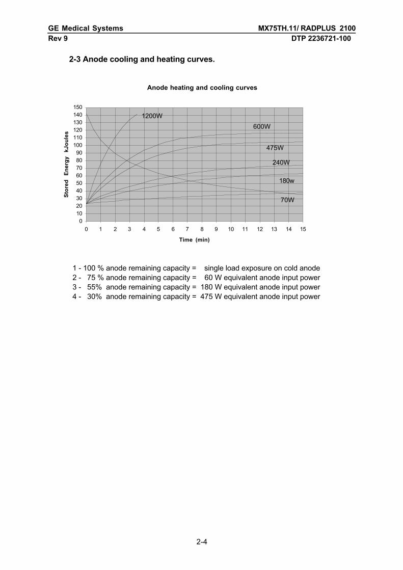
2-3 Anode cooling and heating curves.
Anode heating and cooling curves
0102030405060708090
100110120130140150
0 1 2 3 4 5 6 7 8 9 10 11 12 13 14 15
Time (min)
Sto
red
E
ne
rgy
k
Jo
ule
s
1200W
600W
475W
70W
240W
180w
1 - 100 % anode remaining capacity = single load exposure on cold anode2 - 75 % anode remaining capacity = 60 W equivalent anode input power3 - 55% anode remaining capacity = 180 W equivalent anode input power4 - 30% anode remaining capacity = 475 W equivalent anode input power
GE Medical Systems MX75TH.11/ RADPLUS 2100Rev 9 DTP 2236721-100
3-1
CHAPTER 3 - X-RAY TUBE ASSEMBLY MX 75 TH11 SPECIFICATIONS
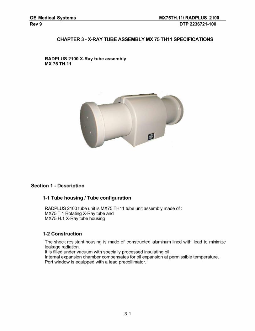
RADPLUS 2100 X-Ray tube assemblyMX 75 TH.11
Section 1 - Description
1-1 Tube housing / Tube configuration
RADPLUS 2100 tube unit is MX75 TH11 tube unit assembly made of :MX75 T.1 Rotating X-Ray tube andMX75 H.1 X-Ray tube housing
1-2 Construction
The shock resistant housing is made of constructed aluminum lined with lead to minimizeleakage radiation.It is filled under vacuum with specially processed insulating oil.Internal expansion chamber compensates for oil expansion at permissible temperature.Port window is equipped with a lead precollimator.
GE Medical Systems MX75TH.11/ RADPLUS 2100Rev 9 DTP 2236721-100
3-2
Section 2 - XRay Tube Assembly MX75TH.11 specifications
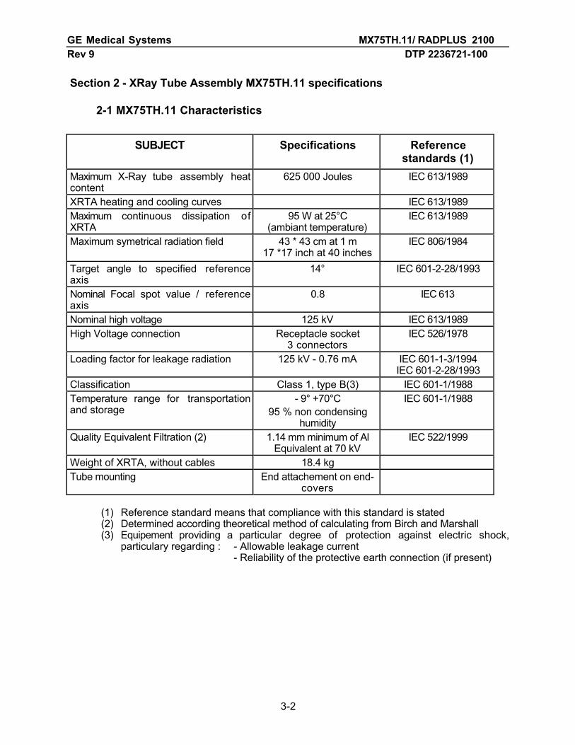
2-1 MX75TH.11 Characteristics
SUBJECT Specifications Referencestandards (1)
Maximum X-Ray tube assembly heatcontent
625 000 Joules IEC 613/1989
XRTA heating and cooling curves IEC 613/1989Maximum continuous dissipation ofXRTA
95 W at 25°C(ambiant temperature)
IEC 613/1989
Maximum symetrical radiation field 43 * 43 cm at 1 m17 *17 inch at 40 inches
IEC 806/1984
Target angle to specified referenceaxis
14° IEC 601-2-28/1993
Nominal Focal spot value / referenceaxis
0.8 IEC 613
Nominal high voltage 125 kV IEC 613/1989High Voltage connection Receptacle socket
3 connectorsIEC 526/1978
Loading factor for leakage radiation 125 kV - 0.76 mA IEC 601-1-3/1994IEC 601-2-28/1993
Classification Class 1, type B(3) IEC 601-1/1988Temperature range for transportationand storage
- 9° +70°C95 % non condensing
humidity
IEC 601-1/1988
Quality Equivalent Filtration (2) 1.14 mm minimum of AlEquivalent at 70 kV
IEC 522/1999
Weight of XRTA, without cables 18.4 kgTube mounting End attachement on end-
covers
(1) Reference standard means that compliance with this standard is stated(2) Determined according theoretical method of calculating from Birch and Marshall(3) Equipement providing a particular degree of protection against electric shock,
particulary regarding : - Allowable leakage current- Reliability of the protective earth connection (if present)
GE Medical Systems MX75TH.11/ RADPLUS 2100Rev 9 DTP 2236721-100
3-3
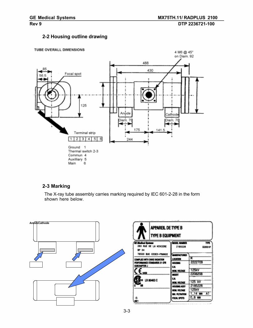
2-2 Housing outline drawing
2-3 Marking
The X-ray tube assembly carries marking required by IEC 601-2-28 in the formshown here below.
AnodeCathode
GE Medical Systems MX75TH.11/ RADPLUS 2100Rev 9 DTP 2236721-100
3-4
2-4 Electrical characteristics
2-4-1 General
MX75H.1 is a bipolar tube housing.Maximum tube voltage, between pole is 125 kV peak value, on rectified or constantvoltage generator balanced relative to ground
2-4-2 Electrical connection
High Voltage connection
The high voltage connects to two identical American (U.S. Federal) Standard typereceptacles on the housing. Installing or removing the high voltage cables requires aspecial wrench.The accessible parts of the X-Ray tube assembly body and flexible conductive housing ofhigh voltage cables shall be connected to the conductive enclosure or the high voltagegenerator.The HV receptacles are designed to operate with isolation grease before the maleconnector is plugged in.
Low voltage connections
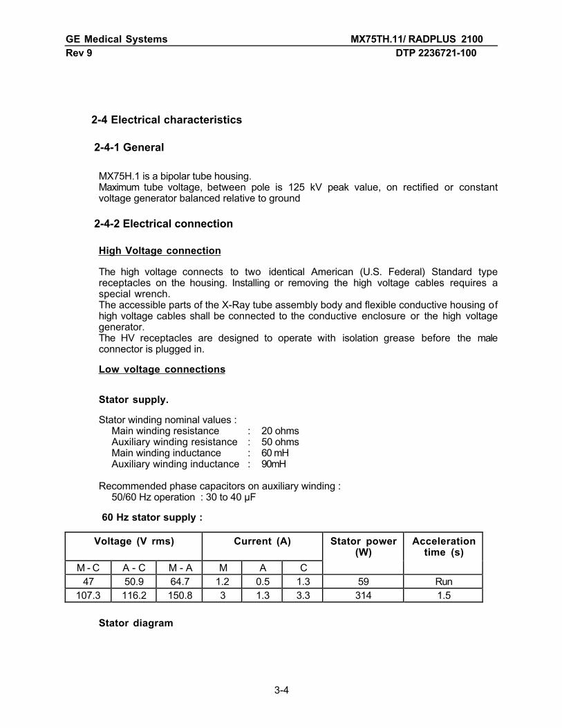
Stator supply.
Stator winding nominal values :Main winding resistance : 20 ohmsAuxiliary winding resistance : 50 ohmsMain winding inductance : 60 mHAuxiliary winding inductance : 90mH
Recommended phase capacitors on auxiliary winding :50/60 Hz operation : 30 to 40 µF
60 Hz stator supply :
Voltage (V rms) Current (A) Stator power(W)
Accelerationtime (s)
M - C A - C M - A M A C47 50.9 64.7 1.2 0.5 1.3 59 Run
107.3 116.2 150.8 3 1.3 3.3 314 1.5
Stator diagram

GE Medical Systems MX75TH.11/ RADPLUS 2100Rev 9 DTP 2236721-100
3-5
20 W
50 W
Starter
M
C
A

GE Medical Systems MX75TH.11/ RADPLUS 2100Rev 9 DTP 2236721-100
3-6
Thermoswitch supply
Thermoswitch can be used at a 250 V max. voltage
COMMUNCOMMON
AUXILIAIREAUXILLIARY
FIL VERT / JAUNE MASSESTRAND GREEN / YELLOW GROUND
THERMO-SWITCHTHERMO-SWITCH
PRINCIPALEMAIN
Main winding : blackAuxilliary winding : greenCommon winding : whiteThermoswitch : redThermoswitch : blueGround : green/yellow
2-5 Thermal characteristics and temperature safety devices
Thermal safety :
Whatever the tube position is, the tube skin temperature will not exceed 60°CA thermoswitch opens the power circuit when its temperature reaches 50°C.

GE Medical Systems MX75TH.11/ RADPLUS 2100Rev 9 DTP 2236721-100
3-7
2-6 Casing cooling and heating curves.
Cooling & Heating @ 95 W Curves. Ambiant 25°C
0
100
200
300
400
500
600
700
1 21 41 61 81 101 121 141 161 181 201 221 241 261 281 301
Time minutes
En
erg
y k
J
Heating and cooling curves are for horizontal mounting of tube assembly in 25°C ambienttemperature. the heating curves take into account all power dissipated in the tubehousing : anode, stator ( run is : 60W), and filament heating (20W).
GE Medical Systems MX75TH.11/ RADPLUS 2100Rev 9 DTP 2236721-100
3-8
Section 3 - Patient, user, assembler and installator safety
CAUTION
Never disconnect the thermal switch !
Always operate the tube with the safety device connected !
3-1 Radiation protection
X-Ray radiation leakage
MX75TH.11 X-Ray tube complies with IEC 601-1-3/1994 EC 601-2-28/1993 specifiedradiation leakage factors : 125 kV - 0.76 mA.
Beam limiting device :
The MX75TH.11 X-ray tube assembly must not be used as an X-ray source assembly.It will be equiped with the beam limiting device reference 46-270615P2 that satisfies theconformity of the prescriptions of CEI 601.1.3.The Quality equivalent filtration of the XRay Tube assembly is not less than 1.14 mm Al.The Quality equivalent filtration of the beam limiting device is not less than 2.0 mm AlSo the Quality equivalent filtration of XRay equipement is not less than 3.14 mm Al andcomplies to the chap.29.201.5 (IEC 601-1-3).
3-2 Electrical protection :
CAUTION
The accessible parts of the X-Ray tube assembly body and flexible conductivehousing of high voltage cables shall be connected to the conductive enclosureof the high voltage generator.
GE Medical Systems MX75TH.11/ RADPLUS 2100Rev 9 DTP 2236721-100
3-9
Section 4 - Installation and maintenance instructions :
4-1 Installation instructions :
Do not operate the tube except in accordance with Information included in presenttechnical documentation, especially « Patient, user, assembler and installator safety »Chap.2, Sec.3.
When installing the tube on the system or during a preventive maintenance call, check thatexposure is disabled when the safety thermal switch is disconnected.
Before applying the first charge, refer to the documentation and to the tube rating charts .
Take into account following into account in determining operating factors
• Electrical characteristics• High voltage rating and wave form• High voltage exposure time• Filament heating current rating• Anode rotation speed• Stator voltage supply
• Thermal characteristics• Heat storage capacity• Anode heating and cooling curves• Cooling and heating curves for tube housing, also taking• into account auxiliary power (stator, filament)• Tube rating charts
The over voltage value which may be produced by the HV generator should not exceedthe maximum acceptable voltage for tube and housing.
For longer life of the rotating anode tube and satisfactory results it is essentialthat calibration or re-calibration of the HV generator be correct. If not, make a newcalibration. Any way, To accommodate power supply fluctuation and kV/mA accuracyuse the tube at 90% or lower of the maximum permissible power.
Warm up
The first exposure of the day, or following two or more hours shutdown, must be madeat a MEDIUM power level rather than voltages or current near maximum ratings. A mediumexposure will test the system for normal function with a minimumrisk of damaging the tube or transformer in the event of a component failure. Thefollowing technique may be used due regard to radiation protection of all personnel
4 exposures, 30 s apartLarge focal spot80 kV Peak - 100 mA - 1 second
GE Medical Systems MX75TH.11/ RADPLUS 2100Rev 9 DTP 2236721-100
3-10
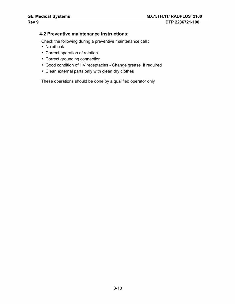
4-2 Preventive maintenance instructions:
Check the following during a preventive maintenance call :• No oil leak
• Correct operation of rotation
• Correct grounding connection
• Good condition of HV receptacles - Change grease if required
• Clean external parts only with clean dry clothes
These operations should be done by a qualified operator only
GE Medical Systems MX75TH.11/ RADPLUS 2100Rev 9 DTP 2236721-100
3-11
Section 5 - Environmental health & safety (EHS) informationThe MX75TH.11 X-ray tube assembly contains potentially dangerous materials but doesnot present any danger as long as it is neither opened nor disassembled.
WARNING
DO NOT DISCARD THE X-RAY TUBE ASSEMBLY AMONG INDUSTRIAL WASTE ORDOMESTIC GARBAGE.
WARNING
A DAMAGED X-RAY TUBE ASSEMBLY SHOULD NOT BE DISPATCHED THROUGH THENATIONAL POSTAL SERVICE.
Your local GEMS field service will advise you on the suitable means of disposal.
The tube assembly to be discarded should be forwarded to the GEMS Service network,and it will be disposed off in a GEMS recycling center.
Dangerous materialsThe X-ray tube assembly contains the following potentially dangerous materials :Lead : Lead salts are toxic and their ingestion may cause serious problems. The workingof lead is subject to regulations.Oil : Univolt 54 mineral oil is not toxic, but the prevailing environmental regulations shouldbe observed for its disposal or recuperation. For example, it is forbidden to dispose ofthis oil in the waste water or sewage system or in the natural environment.
PrecautionsTake all the necessary precautions for the personnel handling the recovery or destructionof X-ray tube assemblies, and in particular against the risks due to lead, or vacuum tubeimplosion.These personnel must be informed of the danger involved and of the necessity toobserve the safety procedures.
Section 6 - Tube unit catalog number :
New tube : D2651 PReplacement tube : D2652 P
Section 7 - Warranty :
The published Company warranty in effect on date of shipment shall apply. Rightreserved to make changes.
GE Medical Systems MX75TH.11/ RADPLUS 2100Rev 9 DTP 2236721-100
3-12
BLANKPAGE

GE Medical Systems MX75TH.11/ RADPLUS 2100Rev 9 DTP 2236721-100
4-1
CHAPTER 4 - RENEWAL PARTS
ABBREVIATIONS
ITEMNO.
- Not illustrated.
- 6 item No. 6 not illustrated.
FRU Field Replaceable Unit.
1 Critical.
2 Not critical.
N Not available.
REP
Y Repairable.
QTY
Previously listed for assembly.
APP Applies to.
Viewing direction.

GE Medical Systems MX75TH.11/ RADPLUS 2100Rev 9 DTP 2236721-100
4-2
ITEM No PART No FRU REP DESCRIPTION QTY
1 2220823 2 END COVER 1
2 99059812 N SCREW M4X20/14 12
3 2238275 1 FRONT COVER (configuration 2) 1
4 2238276 1 BACK COVER (configuration 2) 1
5 2224340 N CABLE MX75TH,11 1
6 99059598 N SCREW M4X8 STAINLESS 1
7 99132746 N WASHER M4 STAINLESS 1
8 2225869 1 THERMO-SWITCH 1
9 99051913 N SCREW M3X5/5 STAINLESS 2
12 99131426 N SCREW LARGE HEAD M5X12/12STEEL
4
13 2247043 N SCREW BULGE HEAD M6 4
14 2240275 N CLAMP 1
16 46-208718P4 N SUPPORT 1
17 46-170015P14 N SCREW 8-32X3/8 2
18 2241328 2 LABEL END COVER 2
19 2237623 1 FRONT COVER (configuration1) 1
20 2237775 1 BACK COVER (configuration 1) 1
21 2238277 1 SEAM COVER (configuration2) 1
22 46-208560P30 N SCREW BINGDING HEAD 10-32X1/2 8

GE Medical Systems MX75TH.11/ RADPLUS 2100Rev 9 DTP 2236721-100
4-3

GE Medical Systems MX75TH.11/ RADPLUS 2100Rev 9 DTP 2236721-100
4-4
RADPLUS 2100 X-Ray tube assembly MX75TH.11
Configuration 1 with front and back cover rework
19
20 2 Holes
22
GE Medical Systems MX75TH.11/ RADPLUS 2100Rev 9 DTP 2236721-100
4-5
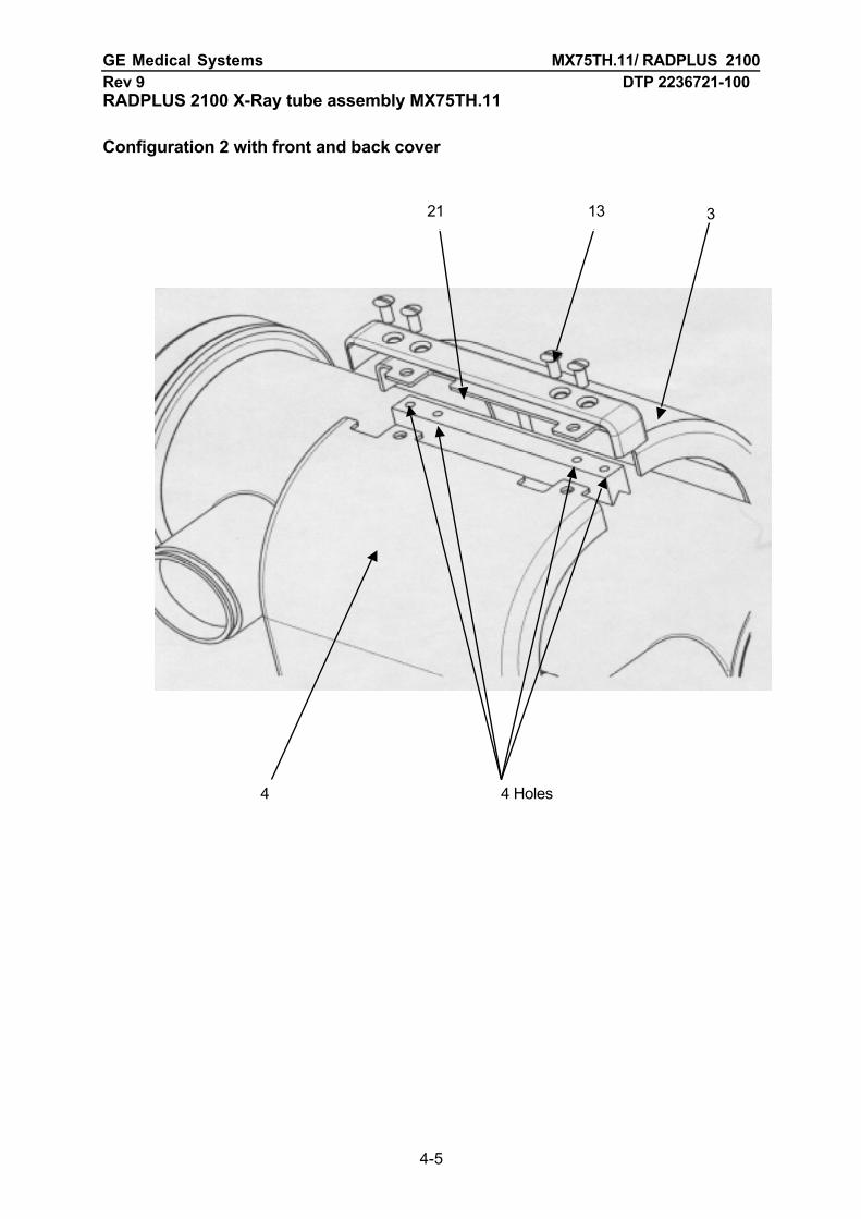
RADPLUS 2100 X-Ray tube assembly MX75TH.11
Configuration 2 with front and back cover
3
4 4 Holes
1321