xa low flow air atomizing spray nozzles - bete can be controlled by adjusting the air flow...
TRANSCRIPT
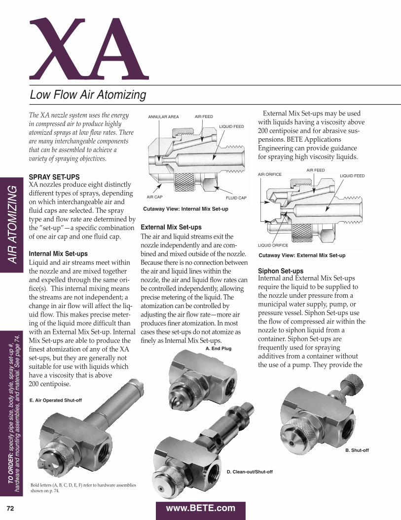
External Mix Set-upsThe air and liquid streams exit thenozzle independently and are combined and mixed outside of the nozzle.Because there is no connection betweenthe air and liquid lines within thenozzle, the air and liquid flow rates canbe controlled independently, allowingprecise metering of the liquid. Theatomization can be controlled byadjusting the air flow rate—more airproduces finer atomization. In mostcases these setups do not atomize asfinely as Internal Mix Setups.
XA
www.BETE.com
Low Flow Air Atomizing
72
The XA nozzle system uses the energy in compressed air to produce highlyatomized sprays at low flow rates. Thereare many interchangeable componentsthat can be assembled to achieve avariety of spraying objectives.
SPRAY SET-UPSXA nozzles produce eight distinctlydifferent types of sprays, dependingon which interchangeable air andfluid caps are selected. The spraytype and flow rate are determined bythe ”setup”—a specific combinationof one air cap and one fluid cap.
Internal Mix Set-upsLiquid and air streams meet withinthe nozzle and are mixed togetherand expelled through the same orifice(s). This internal mixing meansthe streams are not independent; achange in air flow will affect the liquid flow. This makes precise metering of the liquid more difficult thanwith an External Mix Setup. InternalMix Setups are able to produce thefinest atomization of any of the XAsetups, but they are generally notsuitable for use with liquids whichhave a viscosity that is above200 centipoise.
External Mix Setups may be usedwith liquids having a viscosity above200 centipoise and for abrasive suspensions. BETE ApplicationsEngineering can provide guidancefor spraying high viscosity liquids.
Siphon Set-upsInternal and External Mix Setupsrequire the liquid to be supplied tothe nozzle under pressure from amunicipal water supply, pump, orpressure vessel. Siphon Setups usethe flow of compressed air within thenozzle to siphon liquid from a container. Siphon Setups arefrequently used for sprayingadditives from a container withoutthe use of a pump. They provide the
Cutaway View: Internal Mix Set-up
Cutaway View: External Mix Set-up
AIR
ATO
MIZ
ING
E. Air Operated Shut-off
A. End Plug
Bold letters (A, B, C, D, E, F) refer to hardware assembliesshown on p. 74.
D. Clean-out/Shut-off
B. Shut-off
TO O
RD
ER:s
peci
fy p
ipe
size
, bod
y st
yle,
spr
ay s
et-u
p #,
hard
war
e an
d m
ount
ing
asse
mbl
ies,
and
mat
eria
l. S
ee p
age
74.
ANNULAR AREA AIR FEED
LIQUID FEED
AIR FEEDLIQUID FEEDAIR ORIFICE
LIQUID ORIFICE
AIR CAP FLUID CAP

CA
LL 413-772-0846C
all for the name of your nearest B
ET
E representative.
73
A. Plug. The minimum optionhardware assembly required for XAoperation. Provides neither cleanoutnor shutoff.B. Shutoff. Turning the knurledknob will stop the flow of liquid tothe nozzle. Should not be used tometer the flow of liquid.C. Cleanout. Pressing the springloaded plunger will force a smalldiameter rod through the liquidorifice, cleaning any obstruction.Useful for intermittent spraying of aliquid that may dry in the orificewhen not in use.
D. Cleanout/Shutoff. Combinesfunctions of hardware assemblies Band C in one unit.
lowest flow rates available in the XAseries (as low as 0.1 GPH). They aregenerally not suitable for use withliquids having a viscosity above 200centipoise.
By supplying the liquid underpressure, SR Setups may be usedwith liquids having a viscosity above200 centipoise. In this case, the liquidflow rate is regulated by the fluidcap, and can be determined by usingthe EF chart for the specific fluid cap.
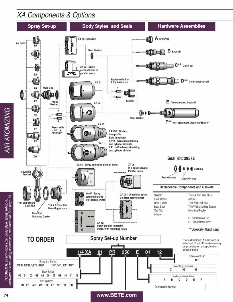
The basic XA nozzle assemblyconsists of a body, a spray setup,and a “hardware assembly” that canprovide shutoff and cleanoutcapabilities.
The XA00 Square Body is the basiccomponent of a nonautomatic XAnozzle. Air and liquid feeds arelocated at opposite ends, perpendicular to the spray.
The XA03 Body has air and liquidfeeds on one side, perpendicular tothe spray axis.
The XA05 Body has air and liquidinlets located inline with the spray.Hardware assemblies cannot be usedwith the XA05 body.
AIR
ATOM
IZING
BASIC OPERATION
Non-Automatic Operation
Hardware Assemblies for Non-Automatic Operation
XA Components & Options
www.BETE.com
XW Air Cap
XA 01/02 Bodywith E or FHardware
PF Air Cap
XA05 Body
XA03 Body
XA00 Body
with C Hardware
Fluid Cap
FF Air Cap
SR Air Cap
PR Air Cap
EF Air CapER Air Cap
XA Components & Options
www.BETE.com74
AIR
ATO
MIZ
ING
TO O
RD
ER:s
peci
fy p
ipe
size
, bod
y st
yle,
spr
ay s
et-u
p #,
hard
war
e an
d m
ount
ing
asse
mbl
ies,
and
mat
eria
l. S
ee p
age
74.
Spray Set-upSpray Set-up Body Styles and SealsBody Styles and Seals Hardware AssembliesHardware Assemblies
ER
SF
SR
PR
PF
AD
EF
FF
XW
Fluid Cap
Front Gasket
Air Caps
XA 00 - Standard
Rear Gasket
Rear Gaskets
Replaceable E orF Tip Assembly
A End Plug
B Shut-off
C** Clean-out
D** Clean-out/Shut-off
E Air-operated Shut-off
F** Air-operated Clean-out/Shut-off
Adapter
ReplaceableE or F TipAssembly
Rear Gasket
Seal Kit: 39572
Bushing
Large O-rings
MountingBracket
Thin Wall MountLock Nut Thick & Thin Wall
Mounting Adapter
Thin WallMounting Gasket
Replaceable Components and Gaskets
Seal KitFront GasketRear GasketBody SealCap NutAdapter
Thick & Thin Wall MountAdapterThin Wall Lock NutThin Wall Mounting GasketMounting Bracket
E - Replacement TipF - Replacement Tip**
**Specify fluid cap
Spray Set-up Number
Sizes and Series1/8”B, 1/4”B, 1/2”B - BSP 1/8”, 1/4”, 1/2” - NPT
Body Styles00 01 02 03 05 06 07 08 10 11 12
Air Cap StylePR FF AD XW PF EF SR SF ER
Mounting Hardware01 02 03
Extension Size*12”
Hardware AssembliesA B C D E F
Combination Number
1/4 XA 01 PR 250 E 01 12
TO ORDER
XA 08 - Directional spray, 2 nozzle spray set-ups
XA 06(4-5 spray setups)Parallel inlets
XA 05 - Spray parallel to parallel inlets
XA 03 - Spray perpendicular to parallel inlets
XA 01
XA 02
*For extensions, A hardware isstandard; E and F hardware maybe provided on an application-specific basis.
XA 12 Spray parallel to parallelinlets. With mounting holes.
XA 10/11 Bodies:Low profileBuilt-in cylinderXA10 – Separate atomizingand cylinder air inletsXA11 – Combined atomizingand cylinder air inlet
XA 07 - Sprayperpendicular to1/8” parallel inlets
XA 10
XA 11
E
F
E
F

For critical applications which require automatic, nodrip, or highspeed spray shutoff, the XA can besupplied with an air cylinderoperated shutoff or cleanout/shutoff. These air cylinders provide virtually instantaneous liquid shutoff atrates of up to 180 cycles per minute.The air cylinders require a minimum of 80 PSI to run that fast.
The XA01, XA02, XA10, and XA11Round Bodies are rugged, highlyreliable, and well suited to the rigorsof highcycle automatic operation.They have been designed to simplifythe feed piping required forinstalling automatic nozzles byproviding a constant location for theair inlet piping. With their neat,professional appearance, they areparticularly recommended for OEMapplications.
The XA01 Round Body has oneinlet for air and one for liquid. Because the air inlet supplies air forboth cylinder movement and liquidatomization, spraying during startup and shutoff is not as crisp andprecise as with the XA02. The XA01body cannot be used with atomizing airpressure under 30 PSI.
The XA02 Round Body has twoinlets for air and one inlet for liquid.One of the air inlets supplies thecylinder and the other suppliesatomizing air. The XA02 body
must be used when the air cylinderoperates at a different pressure fromthe atomizing air or where the atomizing air is supplied below 30 PSI.NOTE: The XA00 Square and XA03Bodies used for nonautomatic operationcan also be used, with hardware assemblies E or F, for automatic operation.Special design features allow fieldupgrading to automatic operation.
The XA10 and XA11 Bodies have abuilt in airoperated cylinder. The integral cylinder provides asmaller profile for use where space is limited.
E. AirOperated Shutoff. Removalof air pressure to the cylinder causesa springloaded poppet valve actuator to shut off liquid flow.F. AirOperated Cleanout/Shutoff.Operation similar to E, but includesa cleanout needle.
Electrically operated solenoid valvescan be used to control the operationof any XA nozzle. BETE can supplysolenoid valves matched to yourspecific application.
A 3way, quickexhaust solenoidvalve is required to operate the E orF hardware assembly. The valve islocated in the line that supplies air to
the cylinder, as close to the nozzle aspossible. Independent control of theatomizing air of an XA02 or squarebody requires an additional 2waysolenoid valve.
Twoway solenoid valves can beused to stop and start the flow of airand liquid to any nonautomatic XA nozzle.
For optimum reliability, everypressurefed XA nozzle should havea strainer and regulator in the liquidfeed line and a filter and regulator inthe air feed line. Every XA nozzlewith a Siphon Feed Setup shouldhave a filter and regulator in the airline. The size and type of each ofthese components depends on theapplication, and can be determinedby your BETE sales representative.BETE maintains an inventory offilters, strainers, and regulators thatcan be supplied with your XA nozzleto ensure reliable operation. Thesecomponents can be purchasedindividually or in kit form.
XA Components & OptionsAUTOMATIC OPERATION
Bodies for Automatic Operation
Hardware Assemblies for Automatic Operation
SOLENOID VALVES
Solenoids for Automatic XA Nozzles.
Solenoids for Non-Automatic XA Nozzles.
FILTERS, REGULATORS AND STRAINERS
Simple piping and robust design describe this multiple nozzle XA lance.
Corrosion-resistant XA in PVC
The XA06 manifold body can befitted with up to five nozzle
setups and is often used forhumidification of large areas.
CA
LL 413-772-0846C
all for the name of your nearest B
ET
E representative.
75
AIR
ATOM
IZING
www.BETE.com

The spray setup can be moved awayfrom the nozzle body by usingoptional 6” or 12” extensions. Theseallow the spray to be moved closer tothe target while keeping the nozzlebody and associated piping at adistance.
In many XA installations the nozzleis supported by the rigid metal pipethat supplies air or liquid. There areseveral components which canprovide support for the XA Bodieswhen it isn’t appropriate to suspendthe nozzle from piping; for example,when the nozzle will spray throughthe wall of a tank or duct, or whenthe air and liquid will be suppliedthrough flexible tubing. All XAbodies except the XA03 can be usedwith any of the mounting hardwaredescribed here.
Threepiece adapter used to supportan XA nozzle with the body locatedoutside a tank or duct having arelatively thin (less than 3/8”) walland the spray directed into theinterior. To use this adapter, a 11/16”diameter hole must be drilledthrough the wall. This adapter bothsecures the air cap and attaches thenozzle body to the tank wall.
Similar in design and function to theThin Wall Adapter, but intended foruse with tanks or ducts with wallsthat are thick enough (3/8” or over)to be drilled and tapped for a 3/4”NPT thread.
This bracket is used in combinationwith a Thin Wall Adapter to supportan XA nozzle from a 1/2”diametermetal rod. The bracket allowsflexibility in aiming the spray.
The standard materials for the XAseries are nickelplated brass and 303and 316 stainless steels. Other metalsand plastics can be supplied onrequest. See page 13 for a completematerial list.
The air cylinders used for XAhardware assemblies E and F haverods and cylinders made of stainlesssteel and end caps made of anodizedaluminum. All metal parts in contactwith the spray liquid are 316 stainless steel.
The standard material for XA gasketsis compressed fiber with a neoprenebinder. For installations requiringFDA approval, SBR gaskets areavailable. Other elastomeric andmetallic gasket materials can besupplied on request.
The standard material for Orings inXA automatics is Viton®. Othermaterials available on request.
XA Components & Options
XA02 with Thin Wall 02 Adapter
XA02 with Thick Wall 01 Adapter
SPRAY EXTENSIONS
MOUNTING HARDWARE
Thin Wall 02 Adapter
Thick Wall 01 Adapter
Mounting Bracket 03 Adapter
MATERIALSBodies, Fluid Caps, Air Caps,Hardware Assemblies, MountingHardware
Air Cylinders
Seals
2XA9890Gasket
2XA9886B - 3/4” BSP2XA9886 - 3/4” NPT
2XA9889Locking nut
Minimum wall thickness
XA03 MountingBracket
BETE can fabricate XA nozzlesinto any number of lance
assembly variations
Automatic XA nozzles in amanifold configuration used forcoating a very wide product
Spray lance (see page 107) with a right angle XA and quick-connect fittings
www.BETE.com76
AIR
ATO
MIZ
ING
TO O
RD
ER:s
peci
fy p
ipe
size
, bod
y st
yle,
spr
ay s
et-u
p #,
hard
war
e an
d m
ount
ing
asse
mbl
ies,
and
mat
eria
l. S
ee p
age
74.
2 5/8”MAX.
Spray Set-up Numbers
PIPESPRAYSIZE SET-UP FLUID AIR
BSP or NPT NO. CAP CAP
EF
EF 050 AC1001EF 100
FC7AC1003
EF 150 FC4 AC1001
1/8
OR
1/4
EF 200 AC1003EF 250
FC3AC1001
EF 300 AC1003
FLATFAN
(EXTERNALMIX)
EF 350 FC6 AC1002EF 400 AC1004EF 450 FC2 AC1002EF 500 AC1004EF 550 FC1 AC1002EF 600 AC1004EF 650 FC8 AC1005EF 700 FC9 AC1005EF 750 FC5 AC1005
1/2 EF 5050 FC501 AC5001
SFSIPHON
FLATFAN
1/8OR1/4
SF 050 FC3 AC1101SF 100 FC6 AC1102
SF 150 FC2 AC1103SF 200 FC2 AC1104
SR
SR 050 FC7 AC1201
1/8OR1/4
SR 150 FC4 AC1201
SIPHONROUND
SR 200 FC4 AC1202SR 250 FC3 AC1202SR 400 FC1 AC1204SR 450 FC5 AC1205
1/2 SR 5050 FC501 AC5201
PF
PF 050 FC4 AC1301PF 100 FC3 AC1303
1/8OR1/4
PF 150 FC3 AC1301
PRESSUREFLATFAN
PF 200 FC3 AC1302PF 250 FC2 AC1304PF 300 FC1 AC1304PF 350 FC1 AC1305PF 400 FC5 AC1306
1/2 PF 5050 FC501 AC5301PF 5100 FC502 AC5302
XWEXTRA
WIDE-ANGLEROUND
1/8 OR 1/4 XW 050 FC8 AC1401
1/2 XW 5050 FC502 AC5401
PR
PR 050 FC4 AC15011/8OR1/4
PR 100 FC4 AC1502PR 150 FC3 AC1502
PRESSURE ROUND
PR 200 FC2 AC1503PR 250 FC1 AC1503PR 300 FC5 AC1504
1/2PR 5050 FC501 AC5501PR 5100 FC502 AC5502
AD
AD 050 FC4 AC1601AD 100 FC2 AC1603AD 150 FC2 AC1602
WIDEANGLEROUND
AD 200 FC1 AC1603AD 250 FC1 AC1604AD 300 FC5 AC1605AD 5050 FC501 AC5601AD 5100 FC501 AC5602AD 5150 FC501 AC5603AD 5200 FC502 AC5604
FF DEFLECTEDFLAT FAN 1/8 OR 1/4 FF 050 FC10 AC1701
1/8OR1/4
SET-UP
1/2
ER NARROWANGLEROUND
ER 050 FC7AC1801ER 150 FC4
ER 250 FC31/8OR1/4
ER 350 FC6AC1802ER 450 FC2
ER 550 FC1ER 650 FC3
AC1803ER 750 FC9ER 850 FC5
XA Components & Options
Overall Dimensions of XA Assemblies with XA00 Body (Shown with E or F Hardware)
Overall Dimensions for Assemblies with XA01 or XA02 Bodies
D i m e n s i on s w i t h H a r d w a r e O p t i on s f o r X A 0 0 B od y , B SP o r N P T
P i pe
S i z e
H a r d w a r e
O p t i on
W X Y M a x . " Z "
A
7 / 8 1 1 1 / 1 6 1 1 5 / 16
9 / 16
1 / 8 B 1 5 / 8
O R C 2 5 / 8
1 / 4 D 3 3 / 1 6
E 4 1 / 1 6
F 4 1 / 1 6
1 / 2 A 1 1 / 4 2 1 / 2 2 1 1 / 16 1
Dimensions in inches
X
W
ZYMAX.
Ø 1 5/8”
4 1/16”1 15/16”MAX.
CENTERLINE FORAIR & LIQUID INLETS
Dimensions are approximate. Check with BETE for critical dimension applications.
2 1/8”MAX.
1 5/8”
Overall Dimensionsfor Assemblies with
XA03 Bodies
Overall Dimensions for Assemblies with
XA05 Bodies
Ø 1 5/8”
CA
LL 413-772-0846C
all for the name of your nearest B
ET
E representative.
77
AIR
ATOM
IZING
www.BETE.com

XA Components & Options
BETE carries a complete line ofcontrols and accessories required for setting up a system usingthe XA Series nozzles.
Contact your BETE representative for details.
In a pressurefed system, theliquid is supplied under pressureto either internal or external mixBETE XA Series nozzles.
Air and liquid regulatorscontrol the fluid delivery pressure, while the air filter and liquidstrainer ensure that the suppliedfluids are free of particulate.
Operational control is maintained by manual orsolenoid valves used inconjunction with the varioushardware assemblies.
In a siphonfed system, theliquid is supplied by either asiphon or gravity feed.
An air regulator controls the airdelivery pressure, while the airfilter ensures that the compressed air is of high quality.
Operational control is maintained by manual or solenoidvalves used in conjunction withthe various hardware assemblies.
When used as a gravity feedsetup, a positive liquid shutoffcapability should be provided.
Filters, regulators, andstrainers matched to your XAapplication are available from stock.
SYSTEM SET-UPS ANDACCESSORIES
Pressure System Set-up
Siphon System Set-up
SIPHON SYSTEM
PRESSURE SYSTEM
www.BETE.com78
AIR
ATO
MIZ
ING
TO O
RD
ER:s
peci
fy p
ipe
size
, bod
y st
yle,
spr
ay s
et-u
p #,
hard
war
e an
d m
ount
ing
asse
mbl
ies,
and
mat
eria
l. S
ee p
age
74.

XAAD
XA AD Set-up Flow Rates and DimensionsPressure Fed, Internal Mix, Wide Angle Round Spray Pattern, 1/8" and 1/4" Pipe Sizes
Spray Dimensions10 PSI Liquid 20 PSI Liquid 30 PSI Liquid 40 PSI Liquid 60 PSI Liquid
PS I GPH SCFMPS I GPH PS I GPH PSI GPH PSI GPH PSI PSI "A" "B" "C" "D"air a ir a ir a ir a ir a ir liquid in . in . in8 1.4 0.4 14 2.1 0.4 22 2.4 0.6 30 2.5 0.7 44 3.0 0.810 1.1 0.4 16 1.9 0.5 26 2.0 0.7 34 2.2 0.8 48 2.7 0.9 10 10 6 7 9 5’0
AD 0 50 12 0.8 0.5 18 1.7 0.6 30 1.6 0.8 38 1.9 0.9 55 2.3 1.2 20 20 6 8 10 6’014 0.5 0.6 20 1.4 0.6 34 1.2 1.0 42 1.5 1.1 60 1.9 1.4 34 30 7 8 10 7’0
22 1.2 0.7 36 0.9 1.1 46 1.1 1.3 65 1.5 1.6 42 40 7 8 11 9’024 0.9 0.8 38 0.7 1.2 48 0.9 1.4 70 1.1 1.8 60 60 8 9 12 12’026 0.6 0.9 40 0.4 1.3 50 0.7 1.5 75 0.7 2.1
12 1.9 1.8 22 3.3 2.3 30 5.1 2.5 38 6.4 2.8 54 8.8 3.414 0.6 2.2 24 2.2 2.8 32 4.3 2.9 42 4.7 3.4 56 8.1 3.7 12 10 7 10 13 6’0
AD 1 00 26 1.2 3.1 34 3.4 3.2 44 3.9 3.7 58 7.4 4.0 24 20 8 10 13 8’036 2.5 3.5 46 3.1 4.1 60 6.8 4.3 34 30 8 10 13 10’038 1.6 3.9 48 2.3 4.4 65 5.1 5.1 46 40 8 11 14 13’040 0.7 4.3 50 1.4 4.8 70 3.5 6.0 60 60 9 11 15 16’0
52 0.6 5.3 75 1.9 7.0
16 3.2 1.4 28 4.6 2.0 42 5.3 2.7 55 5.7 3.3 80 7.1 4.518 2.6 1.6 32 3.4 2.3 46 4.0 3.0 60 4.2 3.7 85 5.8 4.9 22 10 6 8 9 9’0
AD 1 50 20 2.1 1.8 36 2.5 2.6 48 3.5 3.1 65 3.2 4.1 90 4.7 5.3 40 20 7 8 10 15’022 1.6 1.9 40 1.8 2.9 50 3.0 3.3 70 2.3 4.4 95 3.8 5.7 50 30 7 8 10 18’0
1/8 24 1.3 2.1 42 1.5 3.0 55 2.1 3.6 75 1.7 4.8 100 3.0 6.0 70 40 7 9 10 22’026 1.0 2.2 44 1.2 3.1 60 1.5 4.0 80 1.3 5.2 90 60 8 10 11 26’028 0.8 2.4 46 1.0 3.3 65 1.0 4.4 85 1.1 5.6
or10 6.3 1.1 20 9.0 1.6 30 11 .2 2.0 40 12 .4 2.5 56 16 .2 2.812 3.6 1.5 22 6.9 2.0 32 9.3 2.4 42 10 .6 2.9 58 14 .8 3.1 12 10 8 10 14 7’0
1/4 AD 2 00 14 2.0 2.0 24 5.1 2.4 34 7.4 2.8 44 8.8 3.3 60 13 .8 3.5 22 20 8 11 15 10’026 3.3 2.8 36 5.4 3.2 46 7.1 3.7 65 9.8 4.4 34 30 8 11 15 12’0
38 3.6 3.6 48 5.4 4.1 70 6.5 5.4 46 40 8 11 15 15’040 2.3 4.0 50 3.6 4.5 75 4.0 6.3 65 60 8 11 16 19’0
52 2.2 4.9 80 2.4 6.5
18 9.4 3.0 30 13 .4 4.2 44 15 .3 5.5 60 15 .6 7.1 80 21 .4 8.622 7.7 3.6 34 11 .9 4.7 48 13 .8 5.9 70 12 .5 8.3 85 19 .5 9.2 28 10 8 10 13 18’0
AD 2 50 26 6.0 4.1 38 10 .3 5.1 55 11 .3 6.8 80 9.3 9.5 90 17 .9 9.8 42 20 8 11 14 21’028 5.2 4.4 42 8.9 5.6 65 7.8 8.0 85 7.8 10.1 95 16 .5 10.4 65 30 9 11 15 22’030 4.4 4.7 46 7.3 6.1 70 6.1 8.6 90 6.2 10.7 100 15 .1 11.0 85 40 9 12 15 24’032 3.7 5.0 50 5.8 6.7 75 4.5 9.3 95 4.8 11.3 90 60 10 13 16 28’034 3.0 5.3 60 2.4 8.0 80 3.3 9.9 100 3.7 11.9
24 6.7 5.5 38 10 .7 7.4 48 16 .5 8.8 60 18 .6 10.4 85 29 .2 13.726 5.2 5.9 42 7.6 8.3 52 12 .5 9.6 65 13 .7 11.4 90 24 .6 14.7 28 10 10 13 18 18’0
AD 3 00 28 4.0 6.3 44 6.2 8.7 56 9.2 10.4 70 10 .0 12.4 95 20 .7 15.8 46 20 10 14 19 20’030 3.0 6.8 46 5.0 9.1 60 6.6 11.3 75 7.4 13.5 100 17 .5 16.9 60 30 11 15 20 24’032 2.0 7.2 48 4.0 9.5 62 5.6 11.7 80 5.5 14.5 75 40 12 15 21 26’0
50 3.0 9.9 65 4.4 12.3 85 4.0 15.5 90 60 13 17 23 28’052 2.4 10.3 70 2.6 13.3 90 2.5 16.6
Standard Materials: Nickel Plated Brass, 303 Stainless Steel and 316 Stainless Steel.
SCFM SCFM SCFMSCFMPipeSize
Fluidand
Air CapNumbers
SpraySet-up
Number
Fluid CapFC4
&Air CapAC1601
Fluid CapFC2
&Air CapAC1603
Fluid CapFC2
&Air CapAC1602
Fluid CapFC1
&Air CapAC1603
Fluid CapFC1
&Air CapAC1604
Fluid CapFC5
&Air CapAC1605
feet
Pressure-fed/Int. Mix/Wide Angle Round• 70° Hollow Cone spray pattern• Moderate forward spray projection
DESIGN/SPRAY CHARACTERISTICS• Internal mix• Finest atomization
1/4” XA AD100 CXA 00 Body; C Hardware
Dimensions are approximate. Check with BETE for critical dimension applications.
Spray angle performance varies with pressure. Contact BETE for specific data on critical applications.
CA
LL 413-772-0846C
all for the name of your nearest B
ET
E representative.
79
AIR
ATOM
IZING
www.BETE.com
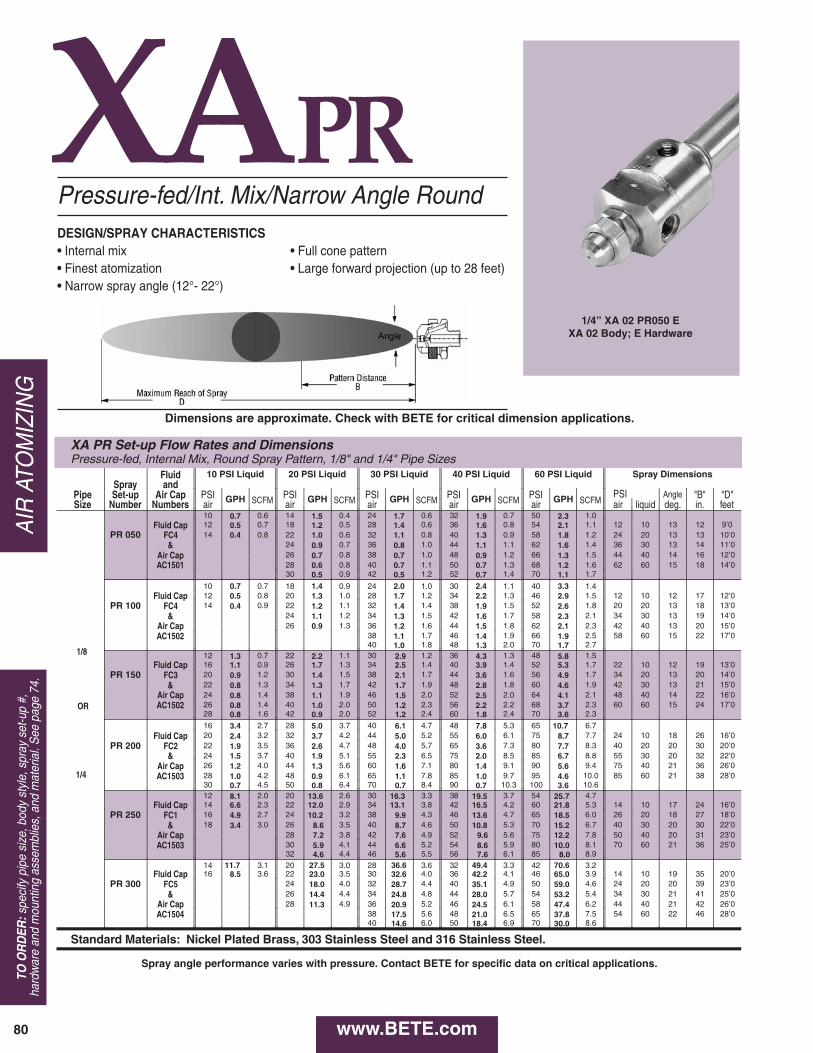
XAPR
XA PR Set-up Flow Rates and Dimensions Pressure-fed, Internal Mix, Round Spray Pattern, 1/8" and 1/4" Pipe Sizes
Fluid 10 PSI Liquid 20 PSI Liquid 30 PSI Liquid 40 PSI Liquid 60 PSI Liquid Spray Dimensions Spray and
Angle Pipe Set-up Air Cap PSI GPH SCFM PSI GPH SCFM PSI GPH SCFM PSI GPH SCFM PSI GPH SCFM "B" "D" Size Number Numbers air air air air air air liquid deg. in. feet
10 0.7 0.6 14 1.5 0.4 24 1.7 0.6 32 1.9 0.7 50 2.3 1.0 Fluid Cap 12 0.5 0.7 18 1.2 0.5 28 1.4 0.6 36 1.6 0.8 54 2.1 1.1 12 10 13 12 9’0
PR 050 FC4 14 0.4 0.8 22 1.0 0.6 32 1.1 0.8 40 1.3 0.9 58 1.8 1.2 24 20 13 13 10’0 & 24 0.9 0.7 36 0.8 1.0 44 1.1 1.1 62 1.6 1.4 36 30 13 14 11’0
Air Cap 26 0.7 0.8 38 0.7 1.0 48 0.9 1.2 66 1.3 1.5 44 40 14 16 12’0 AC1501 28 0.6 0.8 40 0.7 1.1 50 0.7 1.3 68 1.2 1.6 62 60 15 18 14’0
30 0.5 0.9 42 0.5 1.2 52 0.7 1.4 70 1.1 1.7
10 0.7 0.7 18 1.4 0.9 24 2.0 1.0 30 2.4 1.1 40 3.3 1.4 Fluid Cap 12 0.5 0.8 20 1.3 1.0 28 1.7 1.2 34 2.2 1.3 46 2.9 1.5 12 10 12 17 12’0
PR 100 FC4 14 0.4 0.9 22 1.2 1.1 32 1.4 1.4 38 1.9 1.5 52 2.6 1.8 20 20 13 18 13’0 & 24 1.1 1.2 34 1.3 1.5 42 1.6 1.7 58 2.3 2.1 34 30 13 19 14’0
Air Cap 26 0.9 1.3 36 1.2 1.6 44 1.5 1.8 62 2.1 2.3 42 40 13 20 15’0 AC1502 38 1.1 1.7 46 1.4 1.9 66 1.9 2.5 58 60 15 22 17’0
40 1.0 1.8 48 1.3 2.0 70 1.7 2.7 12 1.3 0.7 22 2.2 1.1 30 2.9 1.2 36 4.3 1.3 48 5.8 1.5
Fluid Cap 16 1.1 0.9 26 1.7 1.3 34 2.5 1.4 40 3.9 1.4 52 5.3 1.7 22 10 12 19 13’0 PR 150 FC3 20 0.9 1.2 30 1.4 1.5 38 2.1 1.7 44 3.6 1.6 56 4.9 1.7 34 20 13 20 14’0
& 22 0.8 1.3 34 1.3 1.7 42 1.7 1.9 48 2.8 1.8 60 4.6 1.9 42 30 13 21 15’0 Air Cap 24 0.8 1.4 38 1.1 1.9 46 1.5 2.0 52 2.5 2.0 64 4.1 2.1 48 40 14 22 16’0
1/8
AC1502 26 0.8 1.4 40 1.0 2.0 50 1.2 2.3 56 2.2 2.2 68 3.7 2.3 60 60 15 24 17’0 28 0.8 1.6 42 0.9 2.0 52 1.2 2.4 60 1.8 2.4 70 3.6 2.3
OR
16 3.4 2.7 28 5.0 3.7 40 6.1 4.7 48 7.8 5.3 65 10.7 6.7 Fluid Cap 20 2.4 3.2 32 3.7 4.2 44 5.0 5.2 55 6.0 6.1 75 8.7 7.7 24 10 18 26 16’0
PR 200 FC2 22 1.9 3.5 36 2.6 4.7 48 4.0 5.7 65 3.6 7.3 80 7.7 8.3 40 20 20 30 20’0
1/4
& 24 1.5 3.7 40 1.9 5.1 55 2.3 6.5 75 2.0 8.5 85 6.7 8.8 55 30 20 32 22’0 Air Cap 26 1.2 4.0 44 1.3 5.6 60 1.6 7.1 80 1.4 9.1 90 5.6 9.4 75 40 21 36 26’0 AC1503 28 1.0 4.2 48 0.9 6.1 65 1.1 7.8 85 1.0 9.7 95 4.6 10.0 85 60 21 38 28’0
30 0.7 4.5 50 0.8 6.4 70 0.7 8.4 90 0.7 10.3 100 3.6 10.6 12 8.1 2.0 20 13.6 2.6 30 16.3 3.3 38 19.5 3.7 54 25.7 4.7
Fluid Cap 14 6.6 2.3 22 12.0 2.9 34 13.1 3.8 42 16.5 4.2 60 21.8 5.3 14 10 17 24 16’0 PR 250 FC1 16 4.9 2.7 24 10.2 3.2 38 9.9 4.3 46 13.6 4.7 65 18.5 6.0 26 20 18 27 18’0
& 18 3.4 3.0 26 8.6 3.5 40 8.7 4.6 50 10.8 5.3 70 15.2 6.7 40 30 20 30 22’0 Air Cap 28 7.2 3.8 42 7.6 4.9 52 9.6 5.6 75 12.2 7.8 50 40 20 31 23’0 AC1503 30 5.9 4.1 44 6.6 5.2 54 8.6 5.9 80 10.0 8.1 70 60 21 36 25’0
32 4.6 4.4 46 5.6 5.5 56 7.6 6.1 85 8.0 8.9 14 11.7 3.1 20 27.5 3.0 28 36.6 3.6 32 49.4 3.3 42 70.6 3.2
Fluid Cap 16 8.5 3.6 22 23.0 3.5 30 32.6 4.0 36 42.2 4.1 46 65.0 3.9 14 10 19 35 20’0 PR 300 FC5 24 18.0 4.0 32 28.7 4.4 40 35.1 4.9 50 59.0 4.6 24 20 20 39 23’0
& 26 14.4 4.4 34 24.8 4.8 44 28.0 5.7 54 53.2 5.4 34 30 21 41 25’0 Air Cap 28 11.3 4.9 36 20.9 5.2 46 24.5 6.1 58 47.4 6.2 44 40 21 42 26’0 AC1504 38 17.5 5.6 48 21.0 6.5 65 37.8 7.5 54 60 22 46 28’0
40 14.6 6.0 50 18.4 6.9 70 30.0 8.6
Standard Materials: Nickel Plated Brass, 303 Stainless Steel and 316 Stainless Steel.
PSI
Pressure-fed/Int. Mix/Narrow Angle RoundDESIGN/SPRAY CHARACTERISTICS• Internal mix• Finest atomization• Narrow spray angle (12°- 22°)
• Full cone pattern• Large forward projection (up to 28 feet)
1/4” XA 02 PR050 EXA 02 Body; E Hardware
Dimensions are approximate. Check with BETE for critical dimension applications.
Spray angle performance varies with pressure. Contact BETE for specific data on critical applications.
www.BETE.com80
AIR
ATO
MIZ
ING
TO O
RD
ER:s
peci
fy p
ipe
size
, bod
y st
yle,
spr
ay s
et-u
p #,
hard
war
e an
d m
ount
ing
asse
mbl
ies,
and
mat
eria
l. S
ee p
age
74.

XAPF
XA PF Set-up Flow Rates and Dimensions Pressure-fed, Internal Mix, Flat Spray Pattern, 1/8" and 1/4" Pipe Sizes, BSP or NPT
Fluid 10 PSI Liquid 20 PSI Liquid 30 PSI Liquid 40 PSI Liquid 60 PSI Liquid Spray Dimensions Spray and
Pipe Set-up Air Cap PSI GPH SCFM PSI GPH SCFM PSI GPH SCFM PSI GPH SCFM PSI GPH SCFM PSI A B C D
Size Number Numbers air air air air air air liquid (in.) (in.) (in.) (feet) 10 1.4 0.8 18 2.2 1.5 28 2.5 1.5 38 2.8 1.8 55 3.4 2.4
PF 050
Fluid Cap 12 1.3 1.0 22 1.8 1.6 32 2.2 1.6 42 2.5 2.0 65 2.8 2.9 16 10 10 14 18 8 FC4 14 1.1 1.1 26 1.5 1.8 36 1.9 1.8 46 2.2 2.2 75 2.3 3.3 30 20 14 20 26 9 & 16 0.9 1.2 30 1.2 2.0 40 1.6 2.0 50 1.9 2.4 85 1.7 3.7 40 30 14 20 30 10
Air Cap 18 0.8 1.3 34 0.9 2.2 44 1.3 2.2 60 1.3 2.8 90 1.4 3.9 50 40 18 24 34 11 AC1301 20 0.7 1.4 38 0.7 2.4 48 1.0 2.4 65 0.9 3.0 95 1.1 4.1 85 60 22 28 36 13
22 0.5 1.6 40 0.6 2.7 55 0.7 2.7 70 0.7 3.3 100 0.9 4.3 20 0.8 1.2 34 1.1 1.6 44 1.8 1.9 60 1.6 2.4 80 2.7 2.9
PF 100
Fluid Cap 22 0.6 1.3 36 0.9 1.7 46 1.6 1.9 65 1.2 2.6 85 2.2 3.1 22 10 10 14 18 6 FC3 24 0.5 1.4 38 0.7 1.8 48 1.4 2.0 70 0.8 2.9 90 1.8 3.4 38 20 14 20 28 6 & 26 0.4 1.5 40 0.6 1.9 50 1.1 2.1 46 30 23 28 36 7
Air Cap 28 0.3 1.6 42 0.5 2.0 55 0.7 2.4 60 40 24 28 37 7 AC1303 44 0.4 2.1 80 60 25 30 38 8
12 2.2 0.7 20 3.4 1.0 30 4.0 1.3 38 4.7 1.5 65 4.8 2.4
PF 150
Fluid Cap 14 1.8 0.8 24 2.7 1.1 34 3.4 1.5 42 4.1 1.7 70 4.2 2.6 16 10 14 18 28 7 FC3 16 1.5 1.0 28 2.1 1.3 38 2.9 1.6 46 3.6 1.9 75 3.6 2.9 30 20 16 24 32 8 & 18 1.1 1.1 30 1.8 1.5 42 2.3 1.9 50 3.1 2.1 80 3.1 3.1 42 30 20 26 35 8
Air Cap 20 0.8 1.2 32 1.4 1.6 46 1.7 2.1 60 1.8 2.6 85 2.5 3.4 50 40 22 28 38 9 AC1301 34 1.2 1.7 48 1.4 2.2 65 1.2 2.8 90 2.0 3.6 80 60 23 30 38 10
36 0.9 1.8 50 1.2 2.3 70 0.8 3.1 95 1.6 3.9 14 2.4 0.9 22 3.2 1.1 34 3.4 1.6 40 4.4 1.8 60 5.0 2.5
PF 200
Fluid Cap 16 2.1 1.1 26 2.8 1.4 38 2.9 1.9 44 3.8 2.0 65 4.4 2.7 20 10 4 5 7 10 FC3 18 1.7 1.1 30 2.1 1.6 42 2.3 2.1 48 3.3 2.2 70 3.9 3.0 34 20 5 6 8 12 & 20 1.4 1.3 34 1.5 1.9 46 1.8 2.4 54 2.6 2.6 75 3.4 3.3 46 30 5 7 9 13
1/8 Air Cap 24 0.8 1.5 38 1.2 2.1 50 1.4 2.6 60 1.9 3.0 80 3.0 3.6 54 40 6 9 11 14 AC1302 28 0.5 1.8 42 0.7 2.4 60 0.6 3.2 70 1.1 3.5 90 2.3 4.1 75 60 8 10 12 16
OR 32 0.3 2.0 48 0.4 2.7 70 0.3 3.7 85 0.4 4.3 100 2.0 4.7 16 3.0 1.9 28 4.5 2.7 38 5.9 3.2 46 7.5 3.7 65 9.7 4.8
1/4
PF 250 Fluid Cap 18 2.3 2.1 30 3.9 2.8 40 5.4 3.4 50 6.5 4.0 70 8.6 5.2 20 10 6 7 8 9
FC2 20 1.7 2.3 32 3.3 3.0 42 4.9 3.6 52 5.9 4.2 72 8.0 5.6 32 20 9 11 12 10 & 24 1.3 2.5 34 2.8 3.2 44 4.3 3.7 54 5.4 4.3 80 6.4 6.0 42 30 10 13 18 11
Air Cap 1.0 2.7 36 2.3 3.4 46 3.8 3.9 56 4.9 4.5 85 5.3 6.5 54 40 12 15 18 12 AC1304 48 3.3 4.1 58 4.3 4.7 90 4.3 7.0 75 60 13 16 19 13
60 3.8 4.9 12 7.0 1.2 22 11.5 1.7 34 12.4 2.2 46 13.7 2.8 65 18.3 3.6
PF 300
Fluid Cap 14 5.4 1.4 26 8.3 2.0 38 9.8 2.6 50 10.9 3.1 75 12.6 4.5 16 10 7 9 12 10 FC1 16 4.2 1.6 30 6.0 2.4 42 7.8 3.0 54 8.7 3.5 80 10.6 5.0 32 20 9 12 14 11 & 18 3.3 1.7 32 5.1 2.6 46 5.9 3.3 56 7.8 3.7 85 8.7 5.4 46 30 10 13 16 12
Air Cap 20 2.7 2.0 34 4.3 2.8 48 5.0 3.5 60 6.4 4.1 90 6.9 5.9 56 40 12 15 19 12 AC1304 22 2.0 2.2 36 3.6 3.0 50 4.3 3.7 65 4.6 4.5 95 5.5 6.3 85 60 13 16 20 14
38 3.0 3.2 52 3.7 3.9 70 3.3 5.0 100 4.5 6.8 14 4.5 0.8 24 7.5 1.2 34 9.5 1.7 44 11.1 2.2 56 19.8 2.6
PF 350
Fluid Cap 16 2.9 1.0 26 6.0 1.4 36 7.8 2.0 46 9.7 2.5 60 16.7 3.0 16 10 4 5 6 8 FC1 18 2.0 1.2 28 4.5 1.7 38 6.5 2.2 48 8.4 2.7 65 13.5 3.5 30 20 4 5 7 10 & 20 0.8 1.4 30 3.4 1.8 40 5.2 2.5 52 5.7 3.3 70 9.7 4.3 40 30 5 7 9 11
Air Cap 32 2.4 2.1 42 4.1 2.7 56 3.9 3.8 80 4.8 5.7 52 40 6 8 11 12 AC1305 34 1.3 2.3 46 2.6 3.3 60 2.4 4.4 90 1.8 7.4 70 60 8 10 12 13
36 0.8 2.6 50 1.1 3.7 65 1.1 5.0 95 0.7 8.4 14 7.7 3.2 26 10.5 4.6 34 20.8 4.8 42 29.4 5.2 58 44.7 6.1
PF 400
Fluid Cap 16 5.0 3.8 28 7.0 5.2 36 16.6 5.3 44 25.1 5.6 60 41.0 6.4 14 10 7 8 10 11 FC5 38 12.8 5.8 46 20.8 6.1 65 31.4 7.5 26 20 10 12 16 12 & 40 9.5 6.4 48 16.7 6.6 70 22.5 8.8 38 30 10 12 18 14
Air Cap 42 6.7 6.9 50 13.1 7.2 75 15.0 10.1 48 40 12 16 20 15 AC1306 52 10.1 7.8 80 8.7 11.5 70 60 14 17 23 16
7.3 8.3
Standard Materials: Nickel Plated Brass, 303 Stainless Steel and 316 Stainless Steel.
Pressure-fed/Internal Mix/Flat Fan
• Flat fan, wide angle spray patterns(between 80° and 90°)
DESIGN/SPRAY CHARACTERISTICS• Internal mix• Finest atomization
1/4” XA PF300 AXA 00 Body; A Hardware
Dimensions are approximate. Check with BETE for critical dimension applications.
Spray angle performance varies with pressure. Contact BETE for specific data on critical applications.
CA
LL 413-772-0846C
all for the name of your nearest B
ET
E representative.
81
AIR
ATOM
IZING
www.BETE.com

XASR
XA SR Set-up Flow Rates and Dimensions Siphon-fed, External Mix, Round Spray Pattern, 1/8" and 1/4" Pipe Sizes
Liquid Capacity in GPH ( G allons P er H our) Spray Dimensions at 8" Siphon Height
ATOMIZING Fluid AIR Gravity Head Siphon Height Spray and Air
Pipe Set-up Air Cap PSI Capacity PSI Angle B D Size Number Numbers air SCFM 18" 12" 6" 4" 8" 12" 24" 36" air deg. in. feet
Fluid Cap 10 0.4 0.4 0.4 0.3 0.2 0.2 0.1 0.1
10 18 11 6 SR 050 FC7 20 0.6 0.5 0.4 0.4 0.3 0.3 0.3
0.320 18 11 6
& 40 1.0 0.5 0.5 0.5 0.4 0.4 0.4 0.3
0.2 40 18 12 7 Air Cap 60 1.3 0.6 0.5 0.5 0.4 0.4 0.4 0.2 60 18 14 8 AC1201
Fluid Cap 10 0.8 0.7 0.6 0.5 0.4 0.4 0.3 10 18 12 8 SR 200 FC4 20 1.2 0.8 0.7 0.6 0.6 0.5 0.4 0.2 20 18 13 9
& 40 1.9 0.9 0.9 0.8 0.8 0.7 0.7 0.5 0.3 40 19 15 11 1/8 Air Cap 60 2.7 1.0 1.0 0.9 0.9 0.9 0.8 0.7 0.6 60 20 17 12
AC1202 or
1/4 Fluid Cap 10 0.7 1.2 1.1 0.9 0.6 0.5 0.4 10 21 15 10
SR 250 FC3 20 1.0 1.4 1.3 1.1 0.9 0.8 0.7 0.5 20 21 16 11 & 40 1.7 1.6 1.5 1.3 1.2 1.1 0.9 0.6 0.3 40 21 18 12
Air Cap 60 2.4 1.5 1.4 1.3 1.1 1.0 0.9 0.7 0.5 60 22 20 14 AC1202
Fluid Cap 20 1.9 5.8 5.2 4.2 3.1 2.7 1.9 0.6 20 17 18 12 SR 400 FC1 40 3.0 6.5 6.0 5.1 4.3 3.7 3.0 1.7 0.7 40 18 20 13
& 60 4.1 6.8 6.4 5.6 4.9 4.2 3.5 2.2 1.3 60 18 21 15 Air Cap 80 5.2 6.8 6.4 5.8 5.2 4.5 3.9 2.6 1.6 80 19 23 16 AC1204
Fluid Cap 30 5.3 7.2 6.0 4.6 30 20 20 22 SR 450 FC5 40 6.5 7.8 6.8 5.3 40 20 21 23
& 60 8.8 11.4 10.6 8.3 7.4 6.2 3.2 60 21 23 25 Air Cap 80 11.1 11.6 11.0 10.3 8.3 7.5 6.4 3.6 2.2 80 22 25 27 AC1205
Standard Materials: Nickel Plated Brass, 303 Stainless Steel and 316 Stainless Steel.
Fluid Cap 10 0.5 0.6 0.6 0.5 0.4 0.3 0.2 10 18 12 7 SR 150 FC4 20 0.7 0.7 0.7 0.6 0.5 0.5 0.4 0.2 20 18 13 8
& 40 1.1 0.9 0.8 0.8 0.7 0.7 0.6 0.4 0.3 40 18 15 9 Air Cap 60 1.5 1.0 0.9 0.9 0.8 0.8 0.7 0.6 0.4 60 19 17 10 AC1201
0.1
Siphon-fed Round
• Full cone pattern• Short to moderate forward spray
projection
DESIGN FEATURES• Lowest flow available• Very fine atomization• Narrow spray angle (12°- 22°)
1/4”XA SR 200 BXA 00 Body; B Hardware
Dimensions are approximate. Check with BETE for critical dimension applications.
Spray angle performance varies with pressure. Contact BETE for specific data on critical applications.
www.BETE.com82
AIR
ATO
MIZ
ING
TO O
RD
ER:s
peci
fy p
ipe
size
, bod
y st
yle,
spr
ay s
et-u
p #,
hard
war
e an
d m
ount
ing
asse
mbl
ies,
and
mat
eria
l. S
ee p
age
74.

XASF
XA SF Set-up Flow Rates and DimensionsSiphon-fed, Internal Mix, Flat Fan Spray Pattern, 1/8" and 1/4" Pipe Sizes
Liquid Capacity in GPH (Gallons Per Hour) Spray Dimensions at 8" Siphon Height
ATOMIZINGFluid AIR Gravity Head Siphon HeightSpray and Air
Pipe Set-up Air Cap PSI Capacity PSI "A" "B" "C" "D"Size Number Numbers air SCFM 18" 12" 6" 4" 8" 12" 24" 36" air in in. in feet
Fluid Cap 10 1.0 0.4 0.3 0.3 0.3 0.3 0.2 0.2 0.1 10 8 11 15 7’0SF 050 FC3 20 1.4 0.3 0.3 0.3 0.3 0.3 0.2 0.2 0.2 20 9 12 15 7’0
& 30 1.8 0.2 0.2 0.2 0.1 0.1 30 9 12 15 6’0Air CapAC1101
Fluid Cap 20 1.9 1.0 1.0 0.9 0.8 0.7 0.7 0.6 0.6 20 9 13 15 8’0SF 100 FC6 30 2.4 0.9 0.8 0.8 0.8 0.7 0.7 0.6 0.6 30 10 14 17 9’0
& 40 3.0 0.8 0.7 0.7 0.7 0.6 0.6 0.5 0.5 40 11 15 18 10’01/8 Air Cap 60 4.1 0.4 0.4 0.4 0.3 0.3 0.3 60 11 16 19 9’0
AC1102or
1/4Fluid Cap 20 2.3 1.4 1.3 1.2 1.0 1.0 0.9 0.8 0.6 20 8 9 11 10’0
SF 150 FC2 30 2.9 1.3 1.2 1.1 0.9 0.9 0.8 0.7 0.6 30 8 10 11 11’0& 40 3.5 1.0 0.9 0.9 0.7 0.6 0.5 0.4 40 9 11 12 10’0
Air Cap 50 4.1 0.6 0.5 0.4AC1103
Fluid Cap 20 2.1 2.0 1.9 1.7 1.5 1.4 1.3 1.2 0.9 20 7 9 11 10’0SF 200 FC2 30 2.7 2.0 1.9 1.8 1.6 1.5 1.5 1.3 1.0 30 7 9 12 11’0
& 40 3.3 1.8 1.7 1.6 1.4 1.3 1.2 1.0 40 8 11 13 11’0Air Cap 50 3.9 1.1 1.0 0.9 0.7AC1104
Standard Materials: Nickel Plated Brass, 303 Stainless Steel and 316 Stainless Steel.
Siphon-fed Flat FanDESIGN/SPRAY CHARACTERISTICS• Lowest flow available• Very fine atomization• Flat fan spray pattern
• Moderate spray angle (60° - 85°)• Moderate forward projection• Siphon-fed
1/4”XA02 SF 050 FXA 02 Body; F Hardware
Dimensions are approximate. Check with BETE for critical dimension applications.
Spray angle performance varies with pressure. Contact BETE for specific data on critical applications.
CA
LL 413-772-0846C
all for the name of your nearest B
ET
E representative.
83
AIR
ATOM
IZING
www.BETE.com
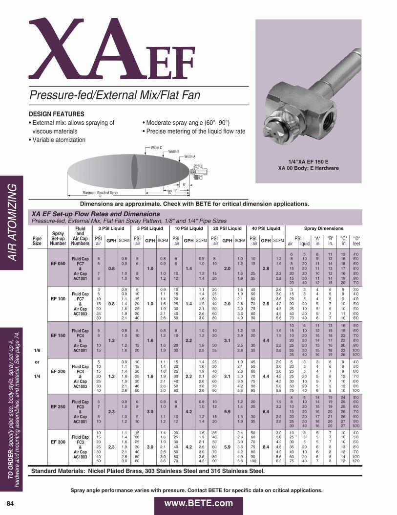
XAEF
XA EF Set-up Flow Rates and Dimensions Pressure-fed, External Mix, Flat Fan Spray Pattern, 1/8" and 1/4" Pipe Sizes
Fluid 3 PSI Liquid 5 PSI Liquid 10 PSI Liquid 20 PSI Liquid 40 PSI Liquid Spray Dimensions Spray and
Pipe Set-up Air Cap PSI GPH SCFM PSI GPH SCFM PSI GPH SCFM PSI GPH SCFM PSI GPH SCFM P S I "A" "B" " C " " D " Size Number Numbers air air air air air air liquid i n . i n . in. feet
6 5 8 1 1 1 3 4’0 Fluid Cap 5 0.8 5 0.8 6 0.9 8 1.0 1 0 1.2 8 1 0 9 1 2 1 6 6’0
EF 050 FC7 6 0.9 6 0.9 8 1.0 1 0 1.2 1 5 1.6 8 2 0 1 1 1 4 1 8 6’0 & 0.8 1.0 1.4 2.0 2.8 15 2 0 11 1 3 17 8 ’ 0
Air Cap 7 1.0 8 1.0 1 0 1.2 1 5 1.6 2 5 2.2 2 0 2 0 1 0 1 2 1 6 8’0 AC1001 8 1.0 1 0 1.2 1 2 1.4 2 0 1.9 3 5 2.8 1 5 3 0 1 1 1 4 1 9 9’0
20 40 12 1 5 20 7 ’ 0
3 0.9 5 0.9 1 0 1.1 2 0 1.6 4 0 2.6 3 3 4 6 9 3’0 Fluid Cap 5 0.9 1 0 1.1 1 5 1.4 2 5 1.9 5 0 3.0 1 5 3 4 6 9 4’0
EF 100 FC7 1 0 1.1 1 5 1.4 2 0 1.6 3 0 2.1 6 0 3.6 2 0 5 4 6 9 4’0 & 15 0.8 1.4 2 0 1.0 1.6 2 5 1.4 1.9 4 0 2.0 2.6 7 0 2.8 4 . 2 20 2 0 5 7 10 5 ’ 0
Air Cap 2 0 1.6 2 5 1.9 3 0 2.1 5 0 3.0 7 5 4.5 2 5 1 0 5 6 1 0 5’0 AC1003 2 5 1.9 3 0 2.1 4 0 2.6 6 0 3.6 8 0 4.9 4 0 2 0 5 7 1 1 6’0
3 0 2.1 4 0 2.6 5 0 3.0 8 0 4.9 9 0 5.6 7 0 4 0 6 7 1 0 8’0
1 0 5 1 1 1 3 1 6 5’0 Fluid Cap 5 0.8 5 0.8 8 1.0 1 0 1.2 1 5 1.6 1 5 1 0 1 2 1 5 1 9 6’0
EF 150 FC4 8 1.0 1 0 1.2 1 0 1.2 2 0 2.9 2 0 1.9 1 0 2 0 1 5 1 8 2 3 7’0 & 1.2 1.6 2.2 3.1 4.4 20 2 0 14 1 7 22 8 ’ 0
Air Cap 1 0 1.2 1 5 1.6 2 0 1.9 3 0 2.5 3 0 2.5 2 5 2 0 1 3 1 6 2 0 9’0 1/8 AC1001 1 5 1 . 6 2 0 1 . 9 3 0 2 . 5 3 5 2 . 8 3 5 2 . 8 2 5 3 0 1 5 1 8 2 3 10’0
2 5 4 0 1 6 1 9 2 6 10’0
or 5 0.9 1 0 1.1 1 5 1.4 2 5 1.9 4 5 2.9 5 3 3 6 9 4’0 Fluid Cap 1 0 1.1 1 5 1.4 2 0 1.6 3 0 2.1 5 0 3.0 2 0 3 4 6 9 5’0
EF 200 FC4 1 5 1.4 2 0 1.6 2 5 1.9 4 0 2.6 6 0 3.6 2 5 5 4 7 9 6’0 1/4 & 20 1.2 1.6 2 5 1.6 1.9 3 0 2.2 2.1 5 0 3.1 3.0 7 0 4.4 4 . 2 25 2 0 5 8 12 7 ’ 0
Air Cap 2 5 1.9 3 0 2.1 4 0 2.6 6 0 3.6 7 5 4.5 3 0 1 0 5 7 1 0 6’0 AC1003 3 0 2.1 4 0 2.6 5 0 3.0 7 0 4.2 9 0 5.6 5 0 2 0 5 9 1 2 8’0
4 0 2 . 6 5 0 3 . 0 6 0 3 . 6 9 0 5 . 6 9 5 5 . 8 7 5 4 0 6 8 1 0 10’0
8 5 14 1 9 24 5 ’ 0 Fluid Cap 6 0.9 6 0.9 6 0.9 1 0 1.2 2 0 1.9 8 1 0 1 4 1 9 2 5 6’0
EF 250 FC3 7 1.0 8 1.0 8 1.0 1 2 1.4 2 5 2.2 1 0 2 0 1 5 1 9 2 5 6’0 & 2.3 3.0 4.2 5.9 8.4 15 2 0 16 2 0 26 7 ’ 0
Air Cap 8 1.0 9 1.1 1 0 1.2 1 5 1.6 3 0 2.5 2 0 2 0 1 7 2 1 2 6 8’0 AC1001 1 0 1.2 1 0 1.2 1 2 1.4 2 0 1.9 3 5 2.8 2 5 3 0 1 6 2 0 2 7 9’0
3 0 4 0 1 6 2 0 2 7 10’0
1 0 1.1 1 5 1.4 2 0 1.6 3 5 2.4 5 0 3.0 1 0 3 5 7 1 0 4’0 Fluid Cap 1 5 1.4 2 0 1.6 2 5 1.9 4 0 2.6 6 0 3.6 2 5 3 5 7 1 0 5’0
EF 300 FC3 2 0 1.6 2 5 1.9 3 0 2.1 5 0 3.0 7 0 4.2 3 0 5 5 7 1 0 6’0 & 25 2.3 1.9 3 0 3.0 2.1 4 0 4.2 2.6 6 0 5.9 3.6 7 5 8.4 4 . 5 35 2 0 6 8 13 8 ’ 0
Air Cap 3 0 2.1 4 0 2.6 5 0 3.0 7 0 4.2 8 0 4.9 4 0 1 0 6 8 1 2 7’0 AC1003 4 0 2 . 6 5 0 3 . 0 6 0 3 . 6 8 0 4 . 9 9 0 5 . 6 6 0 2 0 6 8 1 4 10’0
5 0 3 . 0 6 0 3 . 6 7 0 4 . 2 9 0 5 . 6 1 0 0 6 . 2 7 5 4 0 7 8 1 2 12’0
Standard Materials: Nickel Plated Brass, 303 Stainless Steel and 316 Stainless Steel.
Pressure-fed/External Mix/Flat Fan
• Moderate spray angle (60°- 90°)• Precise metering of the liquid flow rate
DESIGN FEATURES• External mix: allows spraying of
viscous materials• Variable atomization
1/4”XA EF 150 EXA 00 Body; E Hardware
Dimensions are approximate. Check with BETE for critical dimension applications.
Spray angle performance varies with pressure. Contact BETE for specific data on critical applications.
www.BETE.com84
AIR
ATO
MIZ
ING
TO O
RD
ER:s
peci
fy p
ipe
size
, bod
y st
yle,
spr
ay s
et-u
p #,
hard
war
e an
d m
ount
ing
asse
mbl
ies,
and
mat
eria
l. S
ee p
age
74.

XA EF Set-up Flow Rates and Dimensions Pressure-fed, External Mix, Flat Fan Spray Pattern, 1/8" and 1/4" Pipe Sizes
Fluid 3 PSI Liquid 5 PSI Liquid 10 PSI Liquid 20 PSI Liquid 40 PSI Liquid Spray Dimensions Spray and
Pipe Set-up Air Cap PSI GPH SCFM PSI GPH SCFM PSI GPH SCFM PSI GPH SCFM PSI GPH SCFM P S I "A" "B" " C " " D " Size Number Numbers air air air air air air liquid i n . i n . i n . feet
2 0 5 1 3 1 5 1 9 10’0 Fluid Cap 8 3 . 2 1 0 3 . 6 2 0 5 . 5 3 0 7 4 5 1 0 3 0 1 0 1 3 1 6 2 2 12’0
EF 350 FC6 1 0 3 . 6 1 5 4 . 6 3 0 7 . 4 4 0 9 6 0 1 3 3 0 2 0 1 4 1 8 2 3 13’0 & 3.6 4.7 6.6 9.3 13.2 4 5 2 0 1 5 1 9 2 6 14’0
Air Cap 1 5 4 . 6 2 5 6 . 5 3 5 8 . 3 5 0 1 1 7 5 1 5 6 0 2 0 1 5 1 9 2 5 15’0 AC1002 2 0 5 . 5 3 0 7 . 4 4 0 9 . 1 6 0 1 3 8 0 1 6 5 5 3 0 1 6 2 0 2 7 15’0
6 0 4 0 1 5 2 0 2 8 16’0
1 0 3.0 1 5 3.6 2 0 4.1 3 5 6 4 5 8 1 0 3 5 8 1 0 6’0 Fluid Cap 1 5 3.6 2 0 4.1 2 5 4.9 4 0 7 5 0 8 2 5 3 5 8 1 0 8’0
EF 400 FC6 2 0 4 . 1 2 5 4 . 9 3 0 5 . 5 5 0 8 5 5 9 3 0 5 6 8 1 1 10’0 & 25 3.6 4.9 3 0 4.7 5.5 3 5 6.6 6.3 6 0 9.3 9 6 0 13.2 1 0 3 5 1 0 6 9 1 1 11’0
Air Cap 3 0 5 . 5 4 0 6 . 9 4 0 6 . 9 7 0 1 1 7 0 1 1 3 5 2 0 7 9 1 4 12’0 AC1004 4 0 6 . 9 5 0 8 . 0 5 0 8 . 0 8 0 1 3 8 0 1 3 6 0 2 0 7 9 1 5 13’0
5 0 8 . 0 6 0 9 . 4 6 0 9 . 4 9 0 1 5 9 0 1 5 7 0 4 0 7 9 1 3 15’0
1 5 3 1 3 1 5 2 0 11’0Fluid Cap 8 3 . 2 1 0 3 . 6 1 5 4 . 6 3 5 8 5 0 1 1 2 5 1 0 1 4 1 9 2 5 10’0
EF 450 FC2 1 5 4 . 6 2 0 5 . 5 2 5 6 . 5 4 5 1 0 6 5 1 4 3 5 2 0 1 5 1 8 2 5 12’0 & 4.8 6.2 8.7 12.3 17.4 4 5 2 0 1 3 1 7 2 4 14’0
Air Cap 2 0 5 . 5 2 5 6 . 5 3 5 8 . 3 5 5 1 2 8 5 1 7 6 0 2 0 1 2 1 7 2 3 16’0 AC1002 2 5 6 . 5 3 0 7 . 4 4 0 9 . 1 6 0 1 3 9 5 1 9 6 0 3 0 1 3 1 7 2 4 16’0
7 0 4 0 1 3 1 7 2 4 14’0
1/8 1 0 3.0 2 0 4.1 2 5 4.9 4 0 7 5 0 8 1 0 3 6 8 1 1 7’0 Fluid Cap 1 5 3 . 6 2 5 4 . 9 3 0 5 . 5 4 5 8 6 0 1 0 2 5 3 6 8 1 1 10’0
EF 500 FC2 2 0 4 . 1 3 0 5 . 5 3 5 6 . 3 5 0 8 7 0 1 1 3 5 5 6 9 1 3 11’0 or & 25 4.8 4.9 3 5 6.1 6.3 4 0 8.7 6.9 6 0 12.3 9 7 5 17.4 1 2 4 0 1 0 6 9 1 4 12’0
Air Cap 3 0 5 . 5 4 0 6 . 9 5 0 8 . 0 7 0 1 1 8 0 1 3 4 0 2 0 7 1 0 1 5 13’0 AC1004 4 0 6 . 9 5 0 8 . 0 6 0 9 . 4 8 0 1 3 9 0 1 5 6 0 2 0 7 1 0 1 5 14’0
1/4 5 0 8 . 0 6 0 9 . 4 7 0 11.0 9 0 1 5 9 5 1 5 7 5 4 0 7 9 1 4 17’0
3 0 5 1 6 2 2 3 0 11’0 Fluid Cap 1 0 3 . 6 1 5 4 . 6 2 5 6 . 5 4 5 1 0 7 5 1 5 4 0 1 0 1 8 2 3 3 2 13’0
EF 550 FC1 1 5 4 . 6 2 0 5 . 5 3 0 7 . 4 5 0 1 1 8 5 1 7 4 5 2 0 1 9 2 3 3 1 14’0 & 9.9 12.7 18.0 25.5 36.0 6 5 2 0 1 7 2 1 3 0 16’0
Air Cap 2 0 5 . 5 3 0 7 . 4 4 0 9 . 1 7 0 1 4 9 5 1 9 8 0 2 0 1 5 2 0 2 6 19’0 AC1002 2 5 6 . 5 3 5 8 . 3 4 5 10.0 8 0 1 6 100 1 9 5 5 3 0 1 9 2 5 3 3 14’0
9 0 4 0 1 6 2 2 3 1 18’0
1 5 3.6 2 5 4.9 3 5 6 4 5 8 5 5 9 1 5 3 6 8 1 0 8’0 Fluid Cap 2 0 4 . 1 3 0 5 . 5 4 0 7 5 0 8 6 0 1 0 3 0 3 6 9 1 2 10’0
EF 600 FC1 2 5 4 . 9 3 5 6 . 3 4 5 8 5 5 9 6 5 1 1 4 0 5 7 1 0 1 4 11’0 & 30 9.9 5.5 4 0 12.7 6.9 5 0 18.0 8 6 0 25.5 9 7 0 36.0 1 1 4 5 2 0 8 1 1 1 6 12’0
Air Cap 3 5 6 . 3 4 5 7 . 5 6 0 9 7 0 1 1 8 0 1 3 5 0 1 0 8 1 1 1 5 13’0 AC1004 4 0 6 . 9 5 0 8 . 0 7 0 1 1 8 0 1 3 9 0 1 5 6 0 2 0 8 1 1 1 6 14’0
5 0 8 . 0 6 0 9 . 4 8 0 1 3 9 0 1 5 1 0 0 1 6 8 0 4 0 7 1 0 1 5 18’0
2 5 8 2 5 8 3 5 1 1 5 5 1 5 2 5 3 6 8 1 2 10’0 Fluid Cap 3 0 9 3 0 9 4 0 1 2 6 0 1 6 4 0 3 6 8 1 2 11’0
EF 650 FC8 3 5 1 1 3 5 1 1 4 5 1 3 6 5 1 7 4 0 5 6 8 1 2 13’0 & 40 10.0 12 4 0 12.9 12 50 18.0 13 7 0 25.5 1 8 5 0 1 0 7 9 1 3 14’0
Air Cap 4 5 1 3 4 5 1 3 5 5 1 5 7 5 2 0 5 5 2 0 7 9 1 4 15’0 AC1005 5 0 1 3 5 0 1 3 6 0 1 6 8 0 2 1 6 0 1 5 7 9 1 3 15’0
6 0 1 6 6 0 1 6 7 0 1 8 9 0 2 4 7 0 2 0 7 9 1 4 18’0
3 0 9 4 0 1 2 5 5 1 5 7 0 1 8 3 0 3 7 1 0 1 4 11’0 Fluid Cap 3 5 1 1 4 5 1 3 6 0 1 6 7 5 2 0 4 5 3 7 1 0 1 4 13’0
EF 700 FC9 4 0 1 2 5 0 1 3 6 5 1 7 8 0 2 1 5 5 5 7 1 0 1 4 14’0 & 45 17.4 13 5 5 22.5 15 70 31.5 18 8 5 44.7 2 3 7 0 1 0 7 1 0 1 4 17’0
Air Cap 5 0 1 3 6 0 1 6 7 5 2 0 9 0 2 4 7 0 2 0 8 1 0 1 5 18’0 AC1005 6 0 1 6 7 0 1 8 8 0 2 1 7 5 1 5 7 1 0 1 5 18’0
7 0 1 8 8 0 2 1 9 0 2 4 8 0 2 0 8 1 0 1 5 19’0
4 0 1 2 5 0 1 3 6 5 1 7 8 0 2 1 4 0 3 8 1 0 1 4 14’0 Fluid Cap 4 5 1 3 5 5 1 5 7 0 1 8 8 5 2 3 5 5 3 8 1 0 1 5 15’0
EF 750 FC5 5 0 1 3 6 0 1 6 7 5 2 0 9 0 2 4 6 5 5 8 1 0 1 5 17’0 & 55 27.9 15 6 5 36.0 17 80 50.6 21 72.0 7 5 1 0 9 1 1 1 5 18’0
Air Cap 6 0 1 6 7 0 1 8 8 5 2 3 8 0 1 5 9 1 1 1 6 18’0 AC1005 6 5 1 7 7 5 2 0 9 0 2 4 8 0 2 0 9 1 1 1 6 19’0
7 0 1 8 8 0 2 1 8 5 2 0 9 1 1 1 6 19’0
Standard Materials: Nickel Plated Brass, 303 Stainless Steel and 316 Stainless Steel.
Dimensions are approximate. Check with BETE for critical dimension applications.
Spray angle performance varies with pressure. Contact BETE for specific data on critical applications.
CA
LL 413-772-0846C
all for the name of your nearest B
ET
E representative.
85
AIR
ATOM
IZING
www.BETE.com

XAERPressure-fed/Ext. Mix/Narrow Angle Round
1/4” XAER850AXA 00 Body; A Hardware
Dimensions are approximate. Check with BETE for critical dimension applications.
Spray angle performance varies with pressure. Contact BETE for specific data on critical applications.
XA ER Set-up Flow Rates and Spray DimensionsPressure-fed, External Mix, Narrow Round Spray Pattern, 1/8" and 1/4" Pipe Sizes
PipeSize
Spray Fluid and 3 PSI Liquid 5 PSI Liquid 10 PSI Liquid 20 PSI Liquid 40 PSI Liquid Spray DimensionsSet-up Air Cap PSI PSI PSI PSI PSI PSI A B C D
Number Numbers air GPH SCFM air GPH SCFM air GPH SCFM air GPH SCFM air GPH SCFM Liquid Air in in in ft5 0.8 10 1.2 20 1.8 3 10 2 4 5 8
Fluid Cap 5 0.8 5 0.8 10 1.2 20 1.8 30 2.3 5 20 3 4 4 10ER 050 FC7 10 0.7 1.2 10 0.8 1.2 20 1.2 1.8 30 1.7 2.3 40 2.4 2.9 5 40 2 4 5 12
& 20 1.8 20 1.8 30 2.3 40 2.9 50 3.5 10 40 2 3 5 16Air Cap 30 2.3 30 2.3 40 2.9 50 3.5 60 4.0 20 20 3 2 3 14AC1801 40 2.9 50 3.5 60 4.0 70 4.7 20 40 2 3 4 18
80 5.3 90 5.9 40 60 3 3 4 205 0.8 10 1.2 20 1.8 20 1.8 3 10 2 3 3 10
Fluid Cap 5 0.8 10 1.2 20 1.8 30 2.3 30 2.3 5 20 3 3 3 14ER 150 FC4 10 1.0 1.2 20 1.3 1.8 30 2.0 2.3 40 2.7 2.9 40 4.0 2.9 5 40 2 3 5 16
& 20 1.8 30 2.3 40 2.9 50 3.5 50 3.5 10 40 3 3 4 18Air Cap 30 2.3 40 2.9 50 3.5 60 4 60 4.0 20 20 3 3 5 13AC1801 40 2.9 50 3.5 60 4.0 70 4.7 70 4.7 20 40 3 4 4 18
90 5.9 90 5.9 40 60 3 4 6 206 0.9 10 1.2 10 1.2 20 1.8 40 2.9 3 10 3 4 4 10
Fluid Cap 10 1.2 20 1.8 20 1.8 30 2.3 50 3.5 5 20 3 3 5 14ER 250 FC3 20 2.0 1.8 30 2.7 2.3 30 4.0 2.3 40 4.5 2.9 60 6.0 4.0 5 40 3 3 5 14
& 30 2.3 40 2.9 40 2.9 50 3.5 70 4.7 10 40 3 4 5 17Air Cap 40 2.9 50 3.5 50 3.5 60 4.0 80 5.3 20 20 3 4 4 18AC1801 50 3.5 60 4.0 60 4.0 70 4.7 90 5.9 20 40 3 4 5 16
90 5.9 40 60 4 4 5 1710 3.4 10 3.4 30 7.2 40 8.9 3 10 3 5 6 9
Fluid Cap 15 4.5 20 5.5 20 5.5 40 8.9 50 10.6 5 20 3 4 6 11ER 350 FC6 20 3.3 5.5 30 4.1 7.2 30 5.7 7.2 50 8.3 10.6 60 11.9 12.2 5 40 3 4 6 16
& 30 7.2 40 8.9 40 8.9 60 12.2 70 13.9 10 40 3 4 6 16Air Cap 40 8.9 50 10.6 50 10.6 70 13.9 80 15.6 20 30 3 4 6 15AC1802 50 10.6 60 12.2 60 12.2 80 15.6 90 16.7 20 60 3 5 7 17
90 16.7 40 60 3 5 6 1810 3.4 10 3.4 15 4.5 30 7.2 3 10 4 6 9 14
Fluid Cap 15 4.5 15 4.5 20 5.5 40 8.9 40 8.9 5 20 4 5 6 18ER 450 FC2 20 5.0 5.5 20 6.4 5.5 30 8.8 7.2 50 13 10.6 50 18 10.6 5 40 4 5 6 21
& 30 7.2 30 7.2 40 8.9 60 12.2 60 12.2 10 40 5 5 7 22Air Cap 40 8.9 40 8.9 50 10.6 70 13.9 70 13.9 20 30 5 5 6 20AC1802 50 10.6 50 10.6 60 12.2 80 15.6 80 15.6 20 60 4 5 7 22
60 12.2 70 13.9 40 60 4 4 7 2230 7.2 3 20 6 6 9 16
Fluid Cap 15 4.5 20 5.5 40 8.9 40 8.9 50 10.6 5 20 5 6 9 15ER 550 FC1 20 10 5.5 30 13 7.2 50 18 10.6 50 25 10.6 60 30 12.2 5 40 5 7 7 21
& 30 7.2 40 8.9 60 12.2 60 12.2 70 13.9 10 60 6 6 10 22Air Cap 40 8.9 50 10.6 70 13.9 70 13.9 80 15.6 20 40 5 6 7 22AC1802 50 10.6 60 12.2 80 15.6 80 15.6 20 60 5 5 7 22
40 80 4 5 6 2215 7.2 20 8.8 30 11.7 50 17.2 3 20 5 6 8 17
Fluid Cap 20 8.8 25 10.3 40 14.5 55 18.5 5 30 6 6 6 22ER650 FC8 25 10 10.3 30 13 11.7 50 18 17.2 60 25 19.8 5 50 5 5 6 22
& 30 11.7 40 14.5 55 18.5 65 21.1 10 60 5 6 7 22Air Cap 40 14.5 50 17.2 60 19.8 70 22.5 20 50 5 6 6 22AC1803 50 17.2 55 18.5 65 21.1 80 25.2 20 70 4 5 7 18
60 19.8 60 19.8 70 22.5 90 27.9 20 90 4 5 7 1820 8.8 30 11.7 40 14.5 50 17.2 3 20 6 6 9 19
Fluid Cap 30 11.7 40 14.5 50 17.2 55 18.5 5 30 6 6 8 21ER750 FC9 40 17 14.5 50 20 17.2 60 29 19.8 60 42 19.8 5 60 6 7 7 22
& 50 17.2 60 19.8 65 21.1 65 21.1 10 60 5 5 7 22Air Cap 55 18.5 65 21.1 70 22.5 70 22.5 20 50 5 6 8 20AC1803 60 19.8 70 22.5 80 25.2 80 25.2 20 70 4 5 8 19
70 22.5 80 25.2 90 27.9 90 27.9 20 90 4 6 8 1917.2 3 40 6 6 7 22
Fluid Cap 40 14.5 55 18.5 65 21.1 5 70 4 5 7 20ER850 FC5 50 25 17.2 60 29 19.8 70 42 22.5 80 61 25.2 10 80 4 5 7 18
& 55 18.5 65 21.1 80 25.2 90 27.9 10 90 3 4 6 18Air Cap 60 19.8 70 22.5 90 27.9 20 80 4 4 6 18AC1803 65 21.1 80 25.2 20 90 3 4 6 19
1/8”
or
1/4”
DESIGN/SPRAY CHARACTERISTICS• External mix: allows spraying of viscous liquids
• Variable atomization
• Narrow spray angle (10°- 30°)• Precise metering of liquid flow rate
Standard Materials: Nickel Plated Brass, 303 Stainless Steel, and 316 Stainless Steel.
www.BETE.com86
AIR
ATO
MIZ
ING
TO O
RD
ER:s
peci
fy p
ipe
size
, bod
y st
yle,
spr
ay s
et-u
p #,
hard
war
e an
d m
ount
ing
asse
mbl
ies,
and
mat
eria
l. S
ee p
age
74.

XAFFPressure-fed/Int. Mix/Deflected Flat Fan
XAXWPressure-fed/Int. Mix/Extra-wide AngleDESIGN/SPRAY CHARACTERISTICS• Internal mix• 180° Extra-wide hollow cone
DESIGN/SPRAY CHARACTERISTICS• Internal mix• Deflected flat fan spray pattern
1/4”XA 01 FF050 FXA01 Body; F Hardware
1/4”XA 03 XW050 AXA 03 Body; A Hardware
XA FF Set-up Flow RatesPressure-fed, Internal Mix, Deflected Flat Fan Spray Pattern, 1/8" and 1/4" Pipe Sizes
Fluid 10 PSI Liquid 20 PSI Liquid 30 PSI Liquid 40 PSI Liquid 60 PSI LiquidSpray and
Pipe Set-up Air Cap PSI GPH SCFM PSI GPH SCFM PSI GPH SCFM PSI GPH SCFM PSI GPH SCFMSize Number Numbers air air air air air
1/8 Fluid Cap 6 2.9 1.6 14 3.9 2.6 22 4.7 3.3 26 5.8 3.6 38 7.4 4.6FC10 8 2.5 1.9 16 3.5 2.8 24 4.3 3.6 32 4.8 4.4 46 6.4 5.5
or FF 050 & 10 2.0 2.3 18 3.1 3.1 26 4.0 3.8 38 3.8 5.3 54 5.3 6.6Air Cap 12 1.5 2.7 20 2.8 3.5 30 3.3 4.5 44 2.8 6.2 62 4.2 7.8
1/4 AC1701 22 2.3 3.8 34 2.3 5.2 46 2.3 6.6 70 2.8 9.4
XA XW Set-up Flow RatesPressure-fed, Internal Mix, Extra-Wide Spray pattern, 1/8" and 1/4" Pipe Sizes
Fluid 10 PSI Liquid 20 PSI Liquid 30 PSI Liquid 40 PSI Liquid 60 PSI LiquidSpray and
Pipe Set-up Air Cap PSI GPH SCFM PSI GPH SCFM PSI GPH SCFM PSI GPH SCFM PSI GPH SCFMSize Number Numbers air air air air air
Fluid Cap 20 4.0 2.5 34 6.6 4.1 50 7.1 6.4 60 11.0 7.6 85 14.4 11.81/8 FC8 22 2.8 2.7 38 4.4 4.8 52 6.2 6.8 65 8.3 8.6 90 12.0 13.0or XW 050 & 24 2.0 3.0 42 2.8 5.5 56 4.4 7.6 70 6.1 9.8 95 9.8 14.11/4 Air Cap 26 1.5 3.3 46 1.7 6.3 60 3.2 8.4 80 3.1 12.4 100 7.8 15.4
AC1401 28 1.1 3.6 48 1.3 6.9 70 1.3 11.8 90 1.4 15.4
Standard Materials: Nickel Plated Brass, 303 Stainless Steel and 316 Stainless Steel.
CA
LL 413-772-0846C
all for the name of your nearest B
ET
E representative.
87
AIR
ATOM
IZING
www.BETE.com
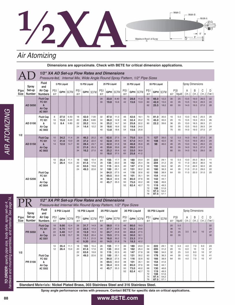
½XA
1/2" XA AD Set-up Flow Rates and DimensionsPressure-fed, Internal Mix, Wide Angle Round Spray Pattern, 1/2" Pipe Sizes
Pipe PS I GPH PS I GPH PS I GPH PS I GPH PS I GPH PSI A B C DSize air air a ir a ir air air liquid ( in .) ( in .) ( in .) ( f ee t )
28 33.0 8.40 40 28.8 11.3 58 66.0 12.2 30 25 13.5 19.0 26.5 2230 19.8 10.8 42 15.6 13.9 60 42.0 15.0 40 35 13.5 19.0 26.5 24
AD 5050 62 25.5 18.2 60 55 14.0 19.5 27.0 28
8 27.0 6.50 18 42.0 7.00 32 47.0 11.0 46 42.6 18.1 70 81.0 30.0 10 5.0 13.0 18.5 25.5 2010 15.0 8.20 20 29.4 8.80 34 36.0 12.8 48 32.4 20.2 75 45.0 35.0 20 15 13.5 19.0 25.5 26
AD 5100 12 8.4 9.80 22 20.2 10.5 36 25.2 14.7 50 25.8 22.2 80 22.2 39.6 36 25 13.0 18.5 26.5 2124 14.4 12.2 38 18.6 16.6 52 19.8 24.0 50 35 13.5 19.0 26.5 24
40 13.8 18.6 54 15.6 25.8 75 55 14.0 19.0 27.0 27
1/210 34.2 11.4 26 46.2 20.2 40 62.6 27.5 54 75.6 32.6 75 127 39.0 12 5.0 14.0 19.5 27.0 2612 21.6 13.0 28 37.2 22.0 42 52.8 29.6 56 57.0 34.3 80 108 42.0 30 15 13.5 19.0 26.5 24
AD 5150 14 12.0 14.7 30 28.4 23.7 44 42.0 31.6 58 46.8 35.8 85 98 46.0 46 25 13.0 18.5 26.0 2332 21.6 25.3 46 33.6 33.6 60 39.0 37.3 60 35 14.0 19.5 27.0 2834 16.2 27.0 48 25.2 35.6 62 33.0 38.8 80 55 14.0 19.5 28.0 30
50 18.0 37.5 65 25.8 41.2
10 35.4 11.1 18 103 15.4 26 155 17.7 36 180 23.0 54 222 29.1 10 5.0 13.0 25.0 36.0 1112 26.4 13.4 20 81.6 17.6 28 135 20.0 38 162 25.4 56 204 31.2 20 15 11.0 26.0 36.0 16
22 63.6 19.8 30 115 22.5 40 147 27.8 58 192 34.0 32 25 11.0 22.0 32.0 2024 49.3 22.6 32 100 25.1 42 131 30.2 60 180 36.3 44 35 11.0 21.0 29.0 22
34 84.0 27.5 44 116 32.6 62 166 38.9 64 55 11.0 22.0 31.0 2536 69.5 30.0 46 101 35.1 64 154 41.6
AD 5200 38 56.4 32.6 48 85.0 37.6 66 142 44.140 45.7 35.3 50 75.0 40.2 68 130 46.6
52 62.4 42.7 70 119 49.372 108 51.674 97.4 54.276 87.5 57.1
1/2" XA PR Set-up Flow Rates and DimensionsPressure-fed Internal Mix Round Spray Pattern, 1/2" Pipe Sizes
5 PSI Liquid 15 PSI Liquid 25 PSI Liquid 35 PSI Liquid 55 PSI Liquid
Pipe PS I GPH PS I GPH PS I GPH PS I GPH PS I GPH PSI A B C DSize air air a ir a ir air air liquid ( in .) ( in .) ( in .) ( f ee t )
18 9.00 12.4 28 31.7 14.9 38 58.0 17.3 48 80.0 19.3 20 5.0
3.5 6.5 10
2220 6.70 13.7 32 22.5 17.0 44 37.7 20.8 54 55.2 23.6 36 15 24
PR 5050 22 5.40 14.7 38 15.9 19.3 50 24.7 24.8 60 40.0 27.5 50 25 2724 4.10 15.7 36 13.2 20.4 54 19.5 27.5 66 30.0 32.1 60 35 30
1/2
40 11.1 21.5 58 16.0 30.2 72 23.3 37.042 9.20 22.6 60 14.5 31.8 78 18.3 42.2
10 35.4 11.1 18 103 15.4 26 155 17.7 36 180 23.0 54 222 29.1 10 5.0 4.0 7.0 9.0 2312 26.4 13.4 20 81.6 17.6 28 135 20.0 36 162 25.4 56 205 31.2 20 15 6.0 10 13 21
22 63.6 19.8 30 115 22.5 40 147 27.8 58 190 34.0 32 25 5.0 8.0 10 3724 49.3 22.6 32 100 25.1 42 131 30.2 60 178 36.3 44 35 4.0 7.0 10 41
34 84.0 27.5 44 116 32.6 62 166 38.9 64 55 4.0 7.0 10 47
PR 5100 36 69.5 30.0 48 101 35.1 64 154 41.638 56.4 32.6 48 85.0 37.6 66 142 44.140 45.7 35.3 50 73.0 40.2 68 130 46.6
52 62.4 42.7 70 119 49.372 108 51.674 97.4 54.276 87.5 57.1
Standard Materials : Nickel Plated Brass, 303 Stainless Steel and 316 Stainless Steel.
SCFM SCFM SCFM SCFM SCFM
SCFMSCFMSCFMSCFMSCFM
5 PSI Liquid 15 PSI Liquid 25 PSI Liquid 35 PSI Liquid 55 PSI Liquid Spray Dimensions
Spray Dimensions
Fluid CapFC 501
&Air CapAC 5601
Fluid CapFC 501
&Air CapAC 5602
Fluid CapFC 501
&Air CapAC 5603
Fluid CapFC 501
&Air CapAC 5604
Fluid CapFC 501
&Air CapAC 5501
Fluid CapFC 502
&Air CapAC 5502
Fluidand
Air CapNumbers
SpraySet-up
Number
Fluidand
Air CapNumbers
SpraySet-up
Number
AD
PR
Air AtomizingDimensions are approximate. Check with BETE for critical dimension applications.
Spray angle performance varies with pressure. Contact BETE for specific data on critical applications.
www.BETE.com88
AIR
ATO
MIZ
ING
TO O
RD
ER:s
peci
fy p
ipe
size
, bod
y st
yle,
spr
ay s
et-u
p #,
hard
war
e an
d m
ount
ing
asse
mbl
ies,
and
mat
eria
l. S
ee p
age
74.
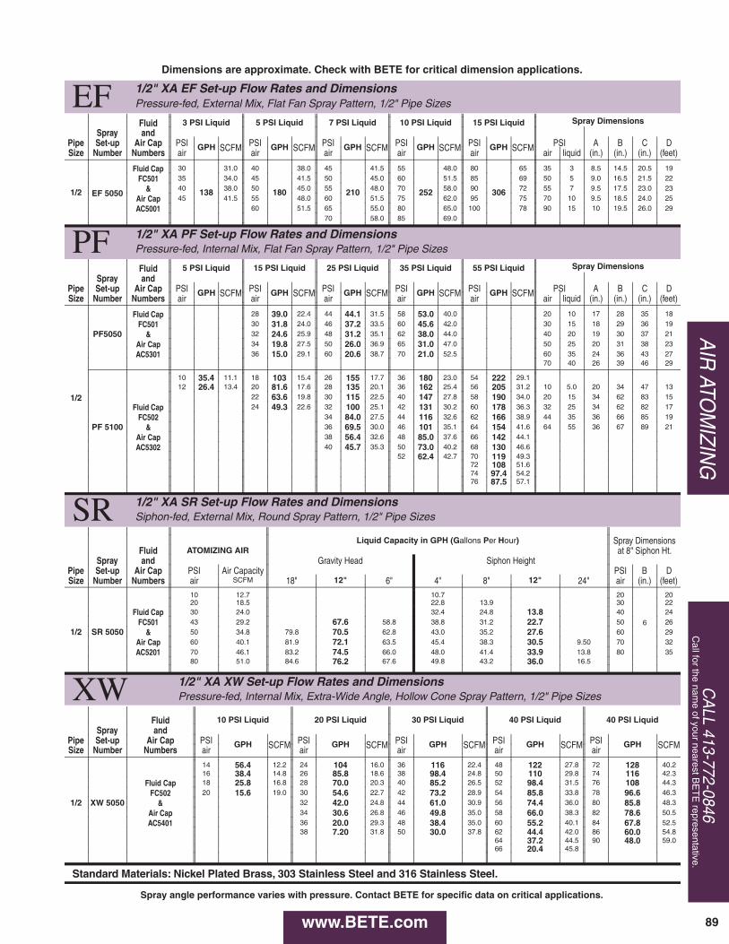
EF 1/2" XA EF Set-up Flow Rates and Dimensions Pressure-fed, External Mix, Flat Fan Spray Pattern, 1/2" Pipe Sizes
Spray Dimensions Fluid 3 PSI Liquid 5 PSI Liquid 7 PSI Liquid 10 PSI Liquid 15 PSI Liquid Spray and
Pipe Set-up Air Cap PSI GPH SCFM PSI GPH SCFM PSI GPH SCFM PSI GPH SCFM PSI GPH SCFM PSI A B C D Size Number Numbers air air air air air air liquid (in.) (in.) (in.) (feet)
1/2
Fluid Cap 30
138
31.0 40
180
38.0 45
210
41.5 55
252
48.0 80
306
65 35 3 8.5 14.5 20.5 19
FC501 35 34.0 45 41.5 50 45.0 60 51.5 85 69 50 5 9.0 16.5 21.5 22
EF 5050 & 40 38.0 50 45.0 55 48.0 70 58.0 90 72 55 7 9.5 17.5 23.0 23
Air Cap 45 41.5 55 48.0 60 51.5 75 62.0 95 75 70 10 9.5 18.5 24.0 25
AC5001 60 51.5 65 55.0 80 65.0 100 78 90 15 10 19.5 26.0 29 70 58.0 85 69.0
PF 1/2" XA PF Set-up Flow Rates and Dimensions Pressure-fed, Internal Mix, Flat Fan Spray Pattern, 1/2" Pipe Sizes
Spray Dimensions Fluid 5 PSI Liquid 15 PSI Liquid 25 PSI Liquid 35 PSI Liquid 55 PSI Liquid Spray and
Pipe Set-up Air Cap PSI GPH SCFM PSI GPH SCFM PSI GPH SCFM PSI GPH SCFM PSI GPH SCFM PSI A B C D Size Number Numbers air air air air air air liquid (in.) (in.) (in.) (feet)
Fluid Cap 28 39.0 22.4 44 44.1 31.5 58 53.0 40.0 20 10 17 28 35 18
FC501 30 31.8 24.0 46 37.2 33.5 60 45.6 42.0 30 15 18 29 36 19
PF5050 & 32 24.6 25.9 48 31.2 35.1 62 38.0 44.0 40 20 19 30 37 21
Air Cap 34 19.8 27.5 50 26.0 36.9 65 31.0 47.0 50 25 20 31 38 23
1/2
AC5301 36 15.0 29.1 60 20.6 38.7 70 21.0 52.5 60 35 24 36 43 27 70 40 26 39 46 29
10 35.4 11.1 18 103 15.4 26 155 17.7 36 180 23.0 54 222 29.1 12 26.4 13.4 20 81.6 17.6 28 135 20.1 36 162 25.4 56 205 31.2 10 5.0 20 34 47 13
22 63.6 19.8 30 115 22.5 40 147 27.8 58 190 34.0 20 15 34 62 83 15
Fluid Cap 24 49.3 22.6 32 100 25.1 42 131 30.2 60 178 36.3 32 25 34 62 82 17
FC502 34 84.0 27.5 44 116 32.6 62 166 38.9 44 35 36 66 85 19
PF 5100 & 36 69.5 30.0 46 101 35.1 64 154 41.6 64 55 36 67 89 21
Air Cap 38 56.4 32.6 48 85.0 37.6 66 142 44.1
AC5302 40 45.7 35.3 50 73.0 40.2 68 130 46.6 52 62.4 42.7 70 119 49.3
72 108 51.6 74 97.4 54.2 76 87.5 57.1
SR 1/2" XA SR Set-up Flow Rates and Dimensions Siphon-fed, External Mix, Round Spray Pattern, 1/2" Pipe Sizes
Liquid Capacity in GPH (G allons P er H our ) Spray Dimensions Fluid ATOMIZING AIR at 8" Siphon Ht.
Spray and Gravity Head Siphon Height Pipe Set-up Air Cap PSI Air Capacity PSI B D Size Number Numbers air SCFM 18" 12" 6" 4" 8" 12" 24" air (in.) (feet)
10 12.7 10.7 20
6
20 20 18.5 22.8 13.9 30 22
Fluid Cap 30 24.0 32.4 24.8 13.8 40 24
FC501 43 29.2 67.6 58.8 38.8 31.2 22.7 50 26 1/2 SR 5050 & 50 34.8 79.8 70.5 62.8 43.0 35.2 27.6 60 29
Air Cap 60 40.1 81.9 72.1 63.5 45.4 38.3 30.5 9.50 70 32
AC5201 70 46.1 83.2 74.5 66.0 48.0 41.4 33.9 13.8 80 35 80 51.0 84.6 76.2 67.6 49.8 43.2 36.0 16.5
XW 1/2" XA XW Set-up Flow Rates and Dimensions Pressure-fed, Internal Mix, Extra-Wide Angle, Hollow Cone Spray Pattern, 1/2" Pipe Sizes
Fluid 10 PSI Liquid 20 PSI Liquid 30 PSI Liquid 40 PSI Liquid 40 PSI Liquid Spray and
Pipe Set-up Air Cap PSI GPH SCFM PSI GPH SCFM PSI GPH SCFM PSI GPH SCFM PSI GPH SCFM Size Number Numbers air air air air air
14 56.4 12.2 24 104 16.0 36 116 22.4 48 122 27.8 72 128 40.2 16 38.4 14.8 26 85.8 18.6 38 98.4 24.8 50 110 29.8 74 116 42.3
Fluid Cap 18 25.8 16.8 28 70.0 20.3 40 85.2 26.5 52 98.4 31.5 76 108 44.3
FC502 20 15.6 19.0 30 54.6 22.7 42 73.2 28.9 54 85.8 33.8 78 96.6 46.3
1/2 XW 5050 & 32 42.0 24.8 44 61.0 30.9 56 74.4 36.0 80 85.8 48.3
Air Cap 34 30.6 26.8 46 49.8 35.0 58 66.0 38.3 82 78.6 50.5
AC5401 36 20.0 29.3 48 38.4 35.0 60 55.2 40.1 84 67.8 52.5 38 7.20 31.8 50 30.0 37.8 62 44.4 42.0 86 60.0 54.8
64 37.2 44.5 90 48.0 59.0 66 20.4 45.8
Standard Materials: Nickel Plated Brass, 303 Stainless Steel and 316 Stainless Steel.
Dimensions are approximate. Check with BETE for critical dimension applications.
Spray angle performance varies with pressure. Contact BETE for specific data on critical applications.
CA
LL 413-772-0846C
all for the name of your nearest B
ET
E representative.
89
AIR
ATOM
IZING
www.BETE.com