xantrex prowatt 1750 owners guide
TRANSCRIPT
Owner’s Guide
PROwatt 1750 Inverter

About XantrexXantrex Technology Inc. is a world-leading supplier of advanced power electronics and controls with products from 50 watt mobile units to 1 MW utility-scale systems for wind, solar, batteries, fuel cells, microturbines, and backup power applications in both grid-connected and standalone systems. Xantrex products include inverters, battery chargers, programmable power supplies, and variable speed drives that convert, supply, control, clean, and distribute electrical power.
TrademarksPROwatt is a trademark of Xantrex International. Xantrex is a registered trademark of Xantrex Technology Inc.Other trademarks, registered trademarks, and product names are the property of their respective owners and are used herein for identification purposes only.
Notice of copyrightPROwatt 1750 Inverter Owner’s Guide © January 2001 Xantrex International. All rights reserved.
DisclaimerWhile every precaution has been taken to ensure the accuracy of the contents of this guide, Xantrex International assumes no responsibility for errors or omissions. Note as well that specifications and product functionality may change without notice.
Date and RevisionMarch 2001, Revision 2
Part number445-0117-01-01
Contact InformationWeb: www.xantrex.comEmail: [email protected]: 1-800-670-0707Fax: 1-800-994-7828

About This Guide
PurposeThe PROwatt 1750 Inverter Owner’s Guide contains information that enables individuals to install, operate, and troubleshoot the PROwatt™ 1750 Inverter.
ScopeThe guide provides safety guidelines, detailed information for designing an installation, procedures for installing the inverter, as well as information about operating and troubleshooting the unit. It does not provide details about particular brands of batteries. You need to consult individual battery manufacturers for this information.
AudienceThe guide is intended for anyone who needs to install and operate the Prowatt 1750. Installers should be certified technicians or electricians.
OrganizationThis guide is organized into five chapters, four appendixes, and an index.
Chapter 1, “Introduction”, outlines the main performance and safety features of the Prowatt 1750. Reading this chapter will give you a clear understanding of the inverter’s capabilities.
Chapter 2, “PROwatt 1750 Features”, outlines the main physical features of the inverter and the components that are shipped with it. This chapter will give you a good orientation to the product before you install it.
iii
About This Guide
Chapter 3, “Installation”, begins by explaining how to plan an effective installation. (Read this chapter in conjunction with Appendix B and Appendix C.) It goes on to give detailed procedures for installing the inverter.
Chapter 4, “Operation”, provides information for turning on and operating the inverter. Details are provided about how to read the front panel indicators to monitor system performance. The chapter also provides information about battery charging frequency and routine maintenance.
Chapter 5, “Troubleshooting”, explains how to solve problems that can occur with the inverter.
Appendix A, “Specifications”, provides electrical, physical, and performance specifications for the inverter and physical specifications for the remote On/Off switch.
Appendix B, “Battery Types and Sizes”, provides background information about battery types as well as information that will help you calculate the size and number of batteries your system requires.
Appendix C, “Alternators and Charging Systems”, describes the components in charging systems and explains how to design a charging system for your installation.
Appendix D, “Product and System Information”, contains the product’s warranty, explains how to return a product for service, and describes how to prepare for a call to Xantrex Customer Service.
The Index provides a valuable means of looking up specific information topics and tasks.
iv
About This Guide
Conventions UsedThe following conventions are used in this guide.
Related InformationYou can find more information about Xantrex Technology Inc. as well as its products and services at www.xantrex.com
WARNING
Warnings identify conditions that could result in personal injury or loss of life.
CAUTION
Cautions identify conditions or practices that could result in damage to the Prowatt 1750 or other equipment.
Note: Notes describe additional information which may add to your understanding of how to use the inverter.
v

vi
vii
Important Safety Information
General Precautions
1. Before installing and using the inverter, read all appropriate sections of this guide as well as all instructions and cautionary markings on the inverter and the batteries.
2. Do not operate the inverter if it has received a sharp blow, been dropped, or otherwise damaged. If the unit is damaged, see “Warranty” on page D–2 and “Return Material Authorization Policy” on page D–3.
3. Do not dismantle the inverter; it contains no user-serviceable components. Attempting to service the unit yourself could cause electrical shock or fire. Internal capacitors remain charged after all power is disconnected.
4. To reduce the risk of electrical shock, disconnect AC and DC power from the inverter before working on any circuits connected to the inverter. Turning off controls will not reduce this risk.
5. Do not expose the inverter to rain, snow, spray, or bilge water.6. To reduce the risk of overheating or fire, do not obstruct the
ventilation openings, and do not install the inverter in a zero-clearance compartment.
Explosive Gas Precautions
1. Batteries generate explosive gases during normal operation. Be sure to read this guide and follow the instructions exactly before installing or using your inverter.
2. This equipment contains components which tend to produce arcs or sparks. To prevent fire or explosion, do not install the inverter in compartments containing batteries or flammable materials or in
WARNING
Before installing and using your PROwatt™ 1750 Inverter, be sure to read and save these safety instructions.
Important Safety Information
locations that require ignition-protected equipment. This includes any space containing gasoline-powered machinery, fuel tanks, as well as joints, fittings, or other connections between components of the fuel system.
Precautions When Working With Batteries
1. Follow all instructions published by the battery manufacturer and the manufacturer of the equipment in which the battery is installed.
2. Make sure the area around the battery is well ventilated.3. Never smoke or allow a spark or flame near the engine or batteries.4. Use caution to reduce the risk of dropping a metal tool on the
battery. It could spark or short circuit the battery or other electrical parts and could cause an explosion.
5. Remove metal items like rings, bracelets, and watches when working with lead-acid batteries. Lead-acid batteries produce a short-circuit current high enough to weld a ring or the like to metal, and thus cause a severe burn.
6. If you need to remove a battery, always remove the ground terminal from the battery first. Make sure all accessories are off so you don’t cause an arc.
Precautions For Using Rechargeable Appliances
Most battery-operated equipment uses a separate charger or transformer that is plugged into an AC receptacle and produces a low voltage output. If the label on the AC adapter or charger states that the adapter or charger produces a low voltage AC or DC output (less than 30 volts), the Prowatt 1750 can power this charger or adapter safely.
Some chargers for small nickel-cadmium batteries can be damaged if connected to the Prowatt 1750. Do not use the following with the PROwatt 1750:
• Small battery-operated appliances like flashlights, razors, and night lights that can be plugged directly into an AC receptacle to recharge
• Chargers for battery packs used in hand power tools. These chargers display a warning label stating that dangerous voltages are present at the battery terminals.
viii

Contents
Important Safety InformationGeneral Precautions - - - - - - - - - - - - - - - - - - - - - - - - - - - - - - - - - - - - - - - - - - viiExplosive Gas Precautions- - - - - - - - - - - - - - - - - - - - - - - - - - - - - - - - - - - - - - viiPrecautions When Working With Batteries - - - - - - - - - - - - - - - - - - - - - - - - - viiiPrecautions For Using Rechargeable Appliances- - - - - - - - - - - - - - - - - - - - - - - viii
1 IntroductionQuality Power - - - - - - - - - - - - - - - - - - - - - - - - - - - - - - - - - - - - - - - - - - - - - 1–2Ease of Use - - - - - - - - - - - - - - - - - - - - - - - - - - - - - - - - - - - - - - - - - - - - - - - 1–2Comprehensive Protection- - - - - - - - - - - - - - - - - - - - - - - - - - - - - - - - - - - - - 1–3
2 PROwatt 1750 FeaturesMaterials List - - - - - - - - - - - - - - - - - - - - - - - - - - - - - - - - - - - - - - - - - - - - - 2–2Front Panel (AC End) - - - - - - - - - - - - - - - - - - - - - - - - - - - - - - - - - - - - - - - - 2–3Back Panel (DC End) - - - - - - - - - - - - - - - - - - - - - - - - - - - - - - - - - - - - - - - - 2–4Remote On/Off Switch - - - - - - - - - - - - - - - - - - - - - - - - - - - - - - - - - - - - - - - 2–5
3 InstallationSafety Instructions - - - - - - - - - - - - - - - - - - - - - - - - - - - - - - - - - - - - - - - - - - 3–2Installation Codes - - - - - - - - - - - - - - - - - - - - - - - - - - - - - - - - - - - - - - - - - - 3–2Installation Tools and Materials - - - - - - - - - - - - - - - - - - - - - - - - - - - - - - - - - 3–2
Tools- - - - - - - - - - - - - - - - - - - - - - - - - - - - - - - - - - - - - - - - - - - - - - - - - - 3–2Materials - - - - - - - - - - - - - - - - - - - - - - - - - - - - - - - - - - - - - - - - - - - - - - - 3–2
Overview of Installation Steps - - - - - - - - - - - - - - - - - - - - - - - - - - - - - - - - - - 3–3Designing Your Installation - - - - - - - - - - - - - - - - - - - - - - - - - - - - - - - - - - - - 3–4
Calculating Battery Requirements - - - - - - - - - - - - - - - - - - - - - - - - - - - - - - 3–4Choosing a Charging System- - - - - - - - - - - - - - - - - - - - - - - - - - - - - - - - - - 3–4
Choosing a Location- - - - - - - - - - - - - - - - - - - - - - - - - - - - - - - - - - - - - - - - - 3–5Connecting to an Existing AC Circuit - - - - - - - - - - - - - - - - - - - - - - - - - - - - - 3–6
AC Wiring Precautions - - - - - - - - - - - - - - - - - - - - - - - - - - - - - - - - - - - - - 3–6
ix
Contents
AC Wiring Procedure- - - - - - - - - - - - - - - - - - - - - - - - - - - - - - - - - - - - - - - 3–7Installing Transfer Switches in AC Circuits - - - - - - - - - - - - - - - - - - - - - - - - 3–8
Installing the Remote On/Off Switch- - - - - - - - - - - - - - - - - - - - - - - - - - - - - 3–10Mounting the Inverter - - - - - - - - - - - - - - - - - - - - - - - - - - - - - - - - - - - - - - - 3–10Connecting the Chassis Ground - - - - - - - - - - - - - - - - - - - - - - - - - - - - - - - - 3–11
Grounding Locations - - - - - - - - - - - - - - - - - - - - - - - - - - - - - - - - - - - - - - 3–11Connecting DC Cables - - - - - - - - - - - - - - - - - - - - - - - - - - - - - - - - - - - - - - 3–12
Cabling Guidelines - - - - - - - - - - - - - - - - - - - - - - - - - - - - - - - - - - - - - - - 3–12Fuse/Circuit Breaker Sizing Guidelines- - - - - - - - - - - - - - - - - - - - - - - - - - 3–13Cabling Procedure - - - - - - - - - - - - - - - - - - - - - - - - - - - - - - - - - - - - - - - - 3–14
4 OperationTurning the Inverter On and Off - - - - - - - - - - - - - - - - - - - - - - - - - - - - - - - - - 4–2Operating Several Loads at Once - - - - - - - - - - - - - - - - - - - - - - - - - - - - - - - - 4–2Turning the Inverter Off Between Charges - - - - - - - - - - - - - - - - - - - - - - - - - - 4–2Using the Remote On/Off Switch - - - - - - - - - - - - - - - - - - - - - - - - - - - - - - - - 4–3Testing the GFCI-Protected AC Outlet - - - - - - - - - - - - - - - - - - - - - - - - - - - - 4–3Reading the Front Panel Indicators - - - - - - - - - - - - - - - - - - - - - - - - - - - - - - - 4–4
Battery Voltage Indicator - - - - - - - - - - - - - - - - - - - - - - - - - - - - - - - - - - - - 4–4Battery Current Indicator - - - - - - - - - - - - - - - - - - - - - - - - - - - - - - - - - - - - 4–4OVER TEMP Indicator - - - - - - - - - - - - - - - - - - - - - - - - - - - - - - - - - - - - - 4–4OVER LOAD Indicator - - - - - - - - - - - - - - - - - - - - - - - - - - - - - - - - - - - - - 4–4
Operating Limits - - - - - - - - - - - - - - - - - - - - - - - - - - - - - - - - - - - - - - - - - - - 4–5Power Output - - - - - - - - - - - - - - - - - - - - - - - - - - - - - - - - - - - - - - - - - - - - 4–5Input Voltage - - - - - - - - - - - - - - - - - - - - - - - - - - - - - - - - - - - - - - - - - - - - 4–5
Inverter Loads - - - - - - - - - - - - - - - - - - - - - - - - - - - - - - - - - - - - - - - - - - - - - 4–6Problem Loads - - - - - - - - - - - - - - - - - - - - - - - - - - - - - - - - - - - - - - - - - - - 4–6Trouble Loads- - - - - - - - - - - - - - - - - - - - - - - - - - - - - - - - - - - - - - - - - - - - 4–6
Battery Charging Frequency - - - - - - - - - - - - - - - - - - - - - - - - - - - - - - - - - - - 4–7Routine Maintenance - - - - - - - - - - - - - - - - - - - - - - - - - - - - - - - - - - - - - - - - 4–7
5 TroubleshootingCommon Problems- - - - - - - - - - - - - - - - - - - - - - - - - - - - - - - - - - - - - - - - - - 5–2
Buzz in Audio Equipment- - - - - - - - - - - - - - - - - - - - - - - - - - - - - - - - - - - - 5–2Television Reception - - - - - - - - - - - - - - - - - - - - - - - - - - - - - - - - - - - - - - - 5–2
Troubleshooting Reference - - - - - - - - - - - - - - - - - - - - - - - - - - - - - - - - - - - - 5–3
x
Contents
A SpecificationsElectrical Performance (Inverter) - - - - - - - - - - - - - - - - - - - - - - - - - - - - - - - - A–2Physical (Inverter) - - - - - - - - - - - - - - - - - - - - - - - - - - - - - - - - - - - - - - - - - - A–2Dimensions (Remote On/Off Switch) - - - - - - - - - - - - - - - - - - - - - - - - - - - - - A–2
B Battery Types and SizesBattery Types - - - - - - - - - - - - - - - - - - - - - - - - - - - - - - - - - - - - - - - - - - - - - B–2
Automotive Starting Batteries - - - - - - - - - - - - - - - - - - - - - - - - - - - - - - - - - B–2Deep-Cycle Lead-Acid Batteries - - - - - - - - - - - - - - - - - - - - - - - - - - - - - - - B–2
Battery Size - - - - - - - - - - - - - - - - - - - - - - - - - - - - - - - - - - - - - - - - - - - - - - B–3Estimating Battery Requirements - - - - - - - - - - - - - - - - - - - - - - - - - - - - - - - - B–4
Battery Sizing Example - - - - - - - - - - - - - - - - - - - - - - - - - - - - - - - - - - - - - B–4Battery Sizing Worksheet - - - - - - - - - - - - - - - - - - - - - - - - - - - - - - - - - - - - B–5
Using Multiple Batteries - - - - - - - - - - - - - - - - - - - - - - - - - - - - - - - - - - - - - - B–6Two Batteries Connected In Parallel- - - - - - - - - - - - - - - - - - - - - - - - - - - - - B–6Two Separate Battery Banks - - - - - - - - - - - - - - - - - - - - - - - - - - - - - - - - - - B–7
Battery Tips - - - - - - - - - - - - - - - - - - - - - - - - - - - - - - - - - - - - - - - - - - - - - - B–8
C Alternators and Charging SystemsCharging System Requirements - - - - - - - - - - - - - - - - - - - - - - - - - - - - - - - - - C–2Charging With an Engine Alternator - - - - - - - - - - - - - - - - - - - - - - - - - - - - - - C–2
Using a Standard Vehicle Alternator- - - - - - - - - - - - - - - - - - - - - - - - - - - - - C–2Using an Alternator Controller - - - - - - - - - - - - - - - - - - - - - - - - - - - - - - - - C–3Using a High-Output Alternator- - - - - - - - - - - - - - - - - - - - - - - - - - - - - - - - C–3
Charging From AC Power - - - - - - - - - - - - - - - - - - - - - - - - - - - - - - - - - - - - - C–3Charging From Alternative Energy Sources - - - - - - - - - - - - - - - - - - - - - - - - - C–3
D Product and System InformationWarranty - - - - - - - - - - - - - - - - - - - - - - - - - - - - - - - - - - - - - - - - - - - - - - - - D–2Return Material Authorization Policy - - - - - - - - - - - - - - - - - - - - - - - - - - - - - D–3Return Material Procedure- - - - - - - - - - - - - - - - - - - - - - - - - - - - - - - - - - - - - D–3Information About Your System- - - - - - - - - - - - - - - - - - - - - - - - - - - - - - - - - D–4Remote On/Off Switch Mounting Template - - - - - - - - - - - - - - - - - - - - - - - - - D–5
Index - - - - - - - - - - - - - - - - - - - - - - - - - - - - - - - - - - - - - - - - - - - - - - 1
xi

xii

1 Introduction
Congratulations on your purchase of the PROwatt 1750 Inverter! As part of the PROwatt Inverter family, the PROwatt 1750 has been designed to give you quality power, ease of use, and outstanding reliability.Please take a few moments to read this chapter to familiarize yourself with the PROwatt 1750’s main performance and protection features.
Introduction
Quality Power
The Prowatt 1750 is a premium-quality inverter designed for high power and industrial applications including large microwaves, TVs, VCRs, small air compressors, power tools, and small air conditioners.
• The Prowatt 1750 provides up to 1750 watts of continuous power, making it ideal for large single loads, intermittent loads, or multiple smaller loads.
• The inverter’s high surge capability lets you handle many hard-to-start loads, including large TVs, refrigerators, and freezers.
• The unit’s low standby battery demand means you don’t have to worry about excessive drain on your battery if you leave the inverter on for a few days. When the inverter is on but no power is being supplied to a load, the inverter draws less than 500 mA from the battery.
• For more efficient power use, the fan shuts down automatically when no loads are attached to the inverter.
Ease of Use
Superior features and rugged durability have been combined with extreme ease of use:
• The unit is compact, light weight, and easy to install.• You can power loads directly from the dual GFCI receptacles on the
front panel, or you can hardwire the unit into an existing AC electrical system using the built-in terminal blocks.
• Easy-to-read indicators on the front panel let you monitor system performance at a glance.
• The remote On/Off switch lets you control the inverter from a convenient location—up to 20 feet (6 m) away—while the inverter itself is mounted out of sight and close to the batteries.
1–2
Comprehensive Protection
Comprehensive Protection
The Prowatt 1750 is equipped with numerous protection features to guarantee safe and trouble-free operation:
Low battery alarm Alerts you if the battery has become discharged to 10.7 V or lower.
Low voltage shutdown Automatically shuts the inverter down if the battery voltage drops below 10 V. This feature protects the battery from being completely discharged.
High voltage shutdown Shuts the inverter down automatically if the input voltage rises to 15 V or more.
Overload shutdown Shuts the unit down automatically if a short circuit occurs or if the loads attached to the inverter exceed the operating limits.
Over temperature shutdown Turns the inverter off if its temperature rises above an acceptable level.
GFCI protection De-energizes the AC circuits and thereby protects the user from electric shock if a ground fault occurs.
1–3

1–4
2 PROwatt 1750 Features
Chapter 2 describes the main features of the Prowatt 1750. Xantrex recommends that you familiarize yourself with them before installing and operating the inverter.

PROwatt 1750 Features
Materials List
Your Prowatt 1750 package includes:
• 1 PROwatt 1750 Inverter• 2 plastic terminal connector covers (boots)—red for positive and
black for negative• 1 Remote On/Off switch and a 20 foot (6 m) communications cable• 1 Owner’s Guide
If any of these materials are missing or are unsatisfactory in any way, please contact Customer Service:
As soon as you unpack your inverter, be sure to record the product information asked for on page D–4.
Phone: 1-800-670-0707Fax: 1-800-994-7828Email: [email protected]
2–2
Front Panel (AC End)
Front Panel (AC End)
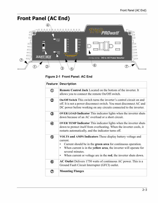
Figure 2-1 Front Panel: AC End
ON
OFF
➀
➆
➆
➃
➅➄
➁ ➂
Feature Description
➀➀➀➀ Remote Control Jack Located on the bottom of the inverter. It allows you to connect the remote On/Off switch.
➁➁➁➁ On/Off Switch This switch turns the inverter’s control circuit on and off. It is not a power disconnect switch. You must disconnect AC and DC power before working on any circuits connected to the inverter.
➂➂➂➂ OVER LOAD Indicator This indicator lights when the inverter shuts down because of an AC overload or a short circuit.
➃➃➃➃ OVER TEMP Indicator This indicator lights when the inverter shuts down to protect itself from overheating. When the inverter cools, it restarts automatically, and the indicator turns off.
➄➄➄➄ VOLTS and AMPS Indicators These display battery voltage and current.• Current should be in the green area for continuous operation.• When current is in the yellow area, the inverter will operate for
several minutes.• When current or voltage are in the red, the inverter shuts down.
➅➅➅➅ AC Outlet Delivers 1750 watts of continuous AC power. This is a Ground Fault Circuit Interrupter (GFCI) outlet.
➆➆➆➆ Mounting Flanges
2–3
PROwatt 1750 Features
Back Panel (DC End)
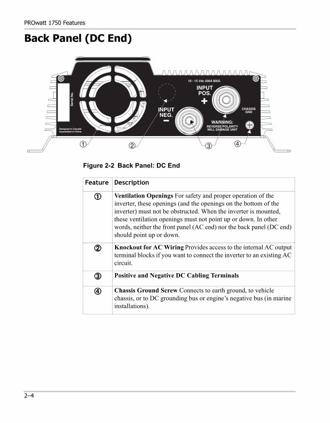
Figure 2-2 Back Panel: DC End
WARNING:REVERSE POLARITYWILL DAMAGE UNIT
Ser
ial N
o.
INPUTPOS.
CHASSISGND
Designed in CanadaAssembled in China
INPUTNEG.
10 - 15 Vdc 200A MAX.
WARNING:REVERSE POLARITYWILL DAMAGE UNIT
Ser
ial N
o.
INPUTPOS.
CHASSISGND
Designed in CanadaAssembled in China
INPUTNEG.
10 - 15 Vdc 200A MAX.
➀ ➁ ➃➂
Feature Description
➀➀➀➀ Ventilation Openings For safety and proper operation of the inverter, these openings (and the openings on the bottom of the inverter) must not be obstructed. When the inverter is mounted, these ventilation openings must not point up or down. In other words, neither the front panel (AC end) nor the back panel (DC end) should point up or down.
➁➁➁➁ Knockout for AC Wiring Provides access to the internal AC output terminal blocks if you want to connect the inverter to an existing AC circuit.
➂➂➂➂ Positive and Negative DC Cabling Terminals
➃➃➃➃ Chassis Ground Screw Connects to earth ground, to vehicle chassis, or to DC grounding bus or engine’s negative bus (in marine installations).
2–4
Remote On/Off Switch
Remote On/Off Switch
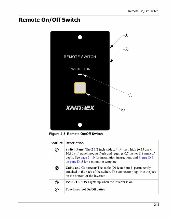
Figure 2-3 Remote On/Off Switch
Feature Description
➀➀➀➀ Switch Panel The 2 1/2 inch wide x 4 1/4 inch high (6.35 cm x 10.80 cm) panel mounts flush and requires 0.7 inches (18 mm) of depth. See page 3–10 for installation instructions and Figure D-1 on page D–5 for a mounting template.
➁➁➁➁ Cable and Connector The cable (20 feet; 6 m) is permanently attached to the back of the switch. The connector plugs into the jack on the bottom of the inverter.
➂➂➂➂ INVERTER ON Lights up when the inverter is on.
➃➃➃➃ Touch control On/Off button
INVERTER ON
REMOTE SWITCH
➀
➁
➂
➃
2–5

2–6
3 Installation
Chapter 3 explains how to install the PROwatt 1750.Xantrex recommends that you read the entire chapter so you can plan an installation that is suited to your power needs and then complete the installation procedures.
Installation
Safety Instructions
Before you start to install the PROwatt 1750:
• Review the “Important Safety Information” on page vii.• Do not attempt your own AC wiring unless you have the knowledge
and experience to do a safe job. Your RV dealer, boat dealer, or a licensed electrician can install the inverter if you do not wish to do your own wiring.
• Read and follow all Warnings and Cautions in this chapter.
Installation Codes
Governing installation codes vary depending on the location and type of installation. Electrical installations must meet local and national wiring codes and should be done by a qualified electrician.
Installation Tools and Materials
Tools
❐ Wire stripper
❐ Flat-head screwdriver
❐ Wrench for DC terminals
❐ Crimping tool for fastening lugs and terminals on DC cables. (You may find it more convenient to have the crimp connectors attached by the company that sells you the cable.)
❐ Drill
Materials
❐ 4 corrosion-resistant fasteners sized #10 or larger for mounting the inverter
❐ Copper DC cable, sized appropriately for load and application
❐ 2, 5/16 inch ring terminals sized for the cable diameter (or Ilsco or equivalent box-lug terminals) to connect the DC cables to the inverter
3–2
Overview of Installation Steps
❐ Lugs and terminals for the DC cables that connect to the battery and fuse holder(s)
❐ DC fuse(s) and fuse holder(s)
❐ AC cable (2-conductor-plus-ground cable), sized appropriately for load and application (if you are connecting to an existing AC circuit)
❐ 1/2 inch cable clamp (if connecting to an existing AC circuit)
❐ AC transfer switch (if connecting to an existing AC circuit that also uses power from another AC source)
❐ Appropriately sized copper cable for the chassis ground
❐ Battery isolator (if connecting to a multiple-battery system)
❐ Battery selector switch*
❐ Alternator controller*
❐ High-output alternator*
* Consult Appendix B and Appendix C to determine whether you need these components.
Overview of Installation Steps
Here’s a summary of the seven main steps:
1. Design the installation: calculate battery capacity and charging requirements.
2. Choose a location.3. Connect to an existing AC circuit (if required).4. Install the remote On/Off switch.5. Mount the inverter.6. Connect the chassis ground.7. Connect the DC cables.
3–3
Installation
Designing Your Installation
Before doing anything else, you need to determine how you are going to use your PROwatt 1750, and on the basis of that, design a power system that will give you maximum performance. The more thorough your planning, the better your power needs will be met. In particular, you need to:
• Calculate your battery requirements• Choose an effective charging system
Calculating Battery Requirements
Battery type and battery size strongly affect the performance of the PROwatt 1750. Therefore, you need to identify the type of loads your inverter will be powering and how much you will be using them between charges. Once you know how much power you will be using, you can determine how much battery capacity you need. Xantrex recommends that you purchase as much battery capacity as possible.
Consult Appendix B “Battery Types and Sizes” for a detailed explanation of how to determine the appropriate number and size of batteries for your needs.
Choosing a Charging System
The charging system must be appropriate for your particular installation. A well-designed charging system will ensure that power is available when you need it and that your batteries remain in top condition. Inadequate charging will degrade system performance, and the wrong type of charger will reduce battery life.
Consult Appendix C “Alternators and Charging Systems” for information about designing an effective charging system.
CAUTIONThe PROwatt 1750 must only be connected to a battery that has a nominal output of 12 volts. It will not operate if connected to a 6 volt battery and will be damaged if connected to a 24 volt battery.
3–4
Choosing a Location
Choosing a Location
The Prowatt 1750 must only be installed in a location that is:
WARNING
The PROwatt 1750 contains components that tend to produce arcs or sparks. To prevent fire or explosion, do not install the inverter in compartments containing batteries or flammable materials or in locations that require ignition-protected equipment.
WARNING
To reduce the risk of fire, do not cover or obstruct the ventilation openings. Do not install the PROwatt 1750 in a zero-clearance compartment. Overheating may result.
Dry Do not allow water or other liquids to drop or splash on it.
Cool Ambient air temperature should be between 32º F and 105º F (0º C and 40º C)—the cooler the better within this range.
Ventilated Allow at least 3 inches (7.5 cm) of clearance around the inverter for air flow. Ensure that ventilation openings on the DC end and the bottom of the unit are not obstructed.
Safe Do not install the inverter in the same compartment as batteries or in any compartment capable of storing flammable liquids like gasoline.
Close to battery
Do not use excessive DC cable lengths: they increase wire resistance and reduce input power. Longer AC wires are preferable to longer DC wires: wire resistance (and therefore voltage drop) is less and the cost is lower.
Protected from battery gases
Do not mount the inverter where it will be exposed to gases produced by the batteries. These gases are very corrosive, and prolonged exposure will damage the inverter.
3–5
Installation
Connecting to an Existing AC Circuit
You can plug loads directly into the AC receptacle on the front panel of the PROwatt 1750. You can also connect the inverter to an existing AC circuit and then plug loads into the receptacles connected to that circuit.
AC Wiring Precautions
If you are going to connect the inverter to existing AC wiring, observe the following precautions when installing and operating the inverter.
Maintain correct wiring polarity.
A modern 115 volt AC wiring system has three color-coded conductors:
• black = line (“hot”)• white = neutral (“common”)• green or bare = ground
Screws on terminals are typically color-coded as follows:
• brass = line• silver = neutral• green = ground
Do not connect the PROwatt 1750 and another AC source (such as a generator or utility power) to the AC wiring at the same time.
The PROwatt 1750 will not operate if its output is connected to AC voltage from another source, and potentially hazardous or damaging conditions may occur. These conditions can occur even if the inverter is switched off.
If you install the Prowatt 1750 into an electrical system that also uses power from a generator or a utility line, you must include a switch that prevents the inverter and the other power source from being connected to the AC distribution system at the same time. See “Installing Transfer Switches in AC Circuits” on page 3–8.
Do not connect the PROwatt 1750 to an AC branch circuit that has high-power consumption loads.
The PROwatt 1750 will not operate electric heaters, air conditioners, stoves, and other electrical appliances that consume more than 1750 watts.
3–6
Connecting to an Existing AC Circuit
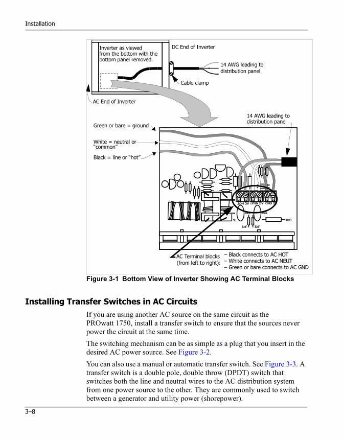
AC Wiring Procedure
To make a permanent connection to existing AC wiring:1. Make sure no DC voltage is being supplied to the inverter, and make
sure no AC voltage is present on the AC wiring.2. Remove the bottom plate from the inverter. This gives you access to
the AC terminal blocks. See Figure 3-1.3. Remove the knockout on the DC end of the inverter.4. Feed 3-conductor 14 AWG AC cable through the hole.5. Insert a cable clamp for electrical junction boxes to hold the cable in
place.6. Connect the ground lead of the AC cable (green or bare wire) to the
internal terminal block labelled AC GND. Connect the other end of the ground lead to a grounding point on a junction box or breaker panel. Make sure the ground lead is cut as short as possible and is not touching any component within the inverter.
7. Strip 1/4 inch (6 mm) of insulation from the line (black) and neutral (white) leads, and connect them to the AC output terminal blocks on the PROwatt 1750 circuit board. These terminal blocks are labeled AC HOT and AC NEUT respectively as shown in Figure 3-1.
Ensure that you have maintained correct polarity and that there are no loose strands of wire.
8. Replace the inverter’s bottom panel.
CAUTION: Reverse Polarity
Improper connections (connecting a line conductor to a neutral conductor, for example) will cause the PROwatt 1750 to malfunction and may permanently damage the inverter.
Damage caused by a reverse polarity connection is not covered by your warranty.
3–7
Installation
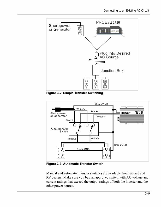
Installing Transfer Switches in AC CircuitsIf you are using another AC source on the same circuit as the PROwatt 1750, install a transfer switch to ensure that the sources never power the circuit at the same time.The switching mechanism can be as simple as a plug that you insert in the desired AC power source. See Figure 3-2.You can also use a manual or automatic transfer switch. See Figure 3-3. A transfer switch is a double pole, double throw (DPDT) switch that switches both the line and neutral wires to the AC distribution system from one power source to the other. They are commonly used to switch between a generator and utility power (shorepower).
Figure 3-1 Bottom View of Inverter Showing AC Terminal Blocks
Inverter as viewed from the bottom with thebottom panel removed.
DC End of Inverter
Cable clamp
14 AWG leading todistribution panel
AC End of Inverter
Black = line or “hot”
White = neutral or
Green or bare = ground
“common”
14 AWG leading todistribution panel
AC Terminal blocks– White connects to AC NEUT– Green or bare connects to AC GND
(from left to right):
– Black connects to AC HOT
3–8
Connecting to an Existing AC Circuit
Manual and automatic transfer switches are available from marine and RV dealers. Make sure you buy an approved switch with AC voltage and current ratings that exceed the output ratings of both the inverter and the other power source.
Figure 3-2 Simple Transfer Switching
Figure 3-3 Automatic Transfer Switch
1750
Shorepoweror Generator
Auto TransferSwitch
Black/L White/N
Black/L
White/NBlack/L
White/N
Green/GND
Green/GND
Green/GND
PROwatt 1750
3–9
Installation
Installing the Remote On/Off SwitchThe remote switch lets you turn the Prowatt 1750 on and off from a convenient location—up to 20 feet (6 m) away from the inverter—while the inverter is mounted out of sight and close to the batteries.
To install the remote On/Off switch:1. Cut out the template printed on page D–5 and position it on the wall
where you want to install the switch.The switch requires a minimum of 0.7 inches (18 mm) of clear depth.
2. Mark the location of the two screw holes and the area to be cut out.3. Pilot drill the two screw holes.4. Cut out the square area.5. Feed the communications cable and connector through the cut-out in
the panel, and route the cable to the jack on the bottom of the inverter.6. Plug the connector into the jack on the bottom of the inverter.7. Fasten the switch assembly using the two screws that are provided.
If you need more cable than the 20 feet (6 m) supplied, buy a 1:1 connector and a high-quality 4-conductor, telephone extension cable with an RJ-11 connector on each end.
You can use a total cable length of 100 feet (30.5 m) although 50 feet (15.25 m) is the maximum recommended.
Mounting the InverterTo mount the Prowatt 1750:1. Turn off the inverter’s On/Off switch.2. Select an appropriate mounting location and orientation. The Prowatt
1750 must be oriented in one of the following ways:• Horizontally on a vertical surface. (The ventilation openings on
the DC end must not point up or down.)• On or under a horizontal surface
3. Hold the inverter against the mounting surface, mark the positions of the mounting screws, and then remove the inverter.
4. Pilot-drill the four mounting holes.5. Fasten the inverter to the mounting surface using corrosion-resistant
hardware sized #10 or larger.
3–10
Connecting the Chassis Ground
Connecting the Chassis Ground
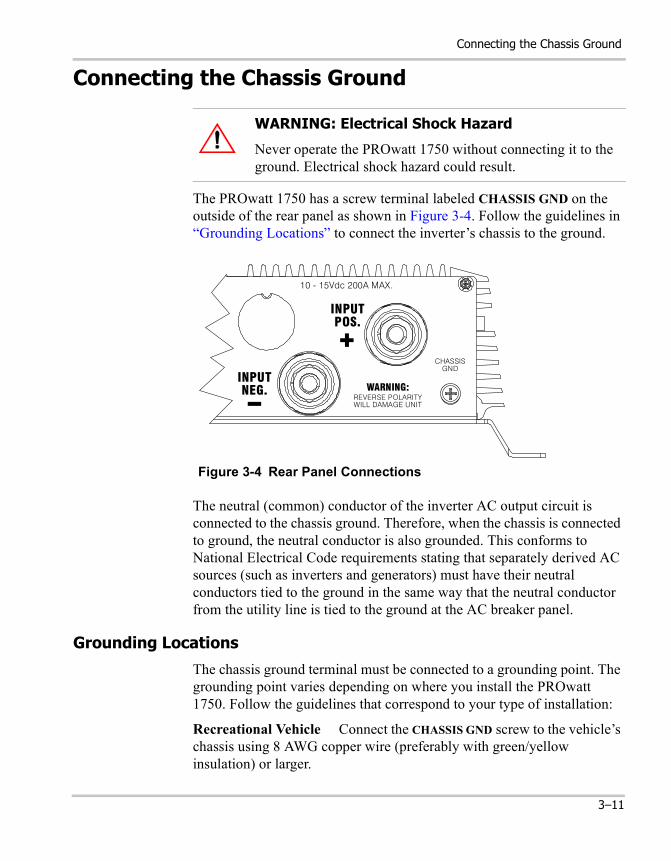
The PROwatt 1750 has a screw terminal labeled CHASSIS GND on the outside of the rear panel as shown in Figure 3-4. Follow the guidelines in “Grounding Locations” to connect the inverter’s chassis to the ground.
The neutral (common) conductor of the inverter AC output circuit is connected to the chassis ground. Therefore, when the chassis is connected to ground, the neutral conductor is also grounded. This conforms to National Electrical Code requirements stating that separately derived AC sources (such as inverters and generators) must have their neutral conductors tied to the ground in the same way that the neutral conductor from the utility line is tied to the ground at the AC breaker panel.
Grounding Locations
The chassis ground terminal must be connected to a grounding point. The grounding point varies depending on where you install the PROwatt 1750. Follow the guidelines that correspond to your type of installation:
Recreational Vehicle Connect the CHASSIS GND screw to the vehicle’s chassis using 8 AWG copper wire (preferably with green/yellow insulation) or larger.
WARNING: Electrical Shock Hazard
Never operate the PROwatt 1750 without connecting it to the ground. Electrical shock hazard could result.
Figure 3-4 Rear Panel Connections
WARNING:REVERSE POLARITYWILL DAMAGE UNIT
CHASSISGND
10 - 15Vdc 200A MAX.
INPUTPOS.
INPUTNEG.
3–11
Installation
Marine Connect the CHASSIS GND screw to the boat’s DC grounding bus or the engine’s negative bus using 2 AWG copper wire that is bare or has insulation rated at 90º C.
Fixed Location (residential, for example) Connect the CHASSIS GND screw to your system’s DC grounding point using 2 AWG wire. The system’s grounding point is usually the AC service entrance grounding point or a separate ground rod. For a solar PV (photovoltaic) installation, this is usually the same rod used to ground the PV array.
Connecting DC Cables
To operate safely and effectively, the PROwatt 1750 needs proper cables, wiring, and fuses. Because the PROwatt 1750 has low-voltage, high-current input, low-resistance wiring between the battery and the inverter is essential to deliver the maximum amount of usable energy to your load.
Cabling Guidelines
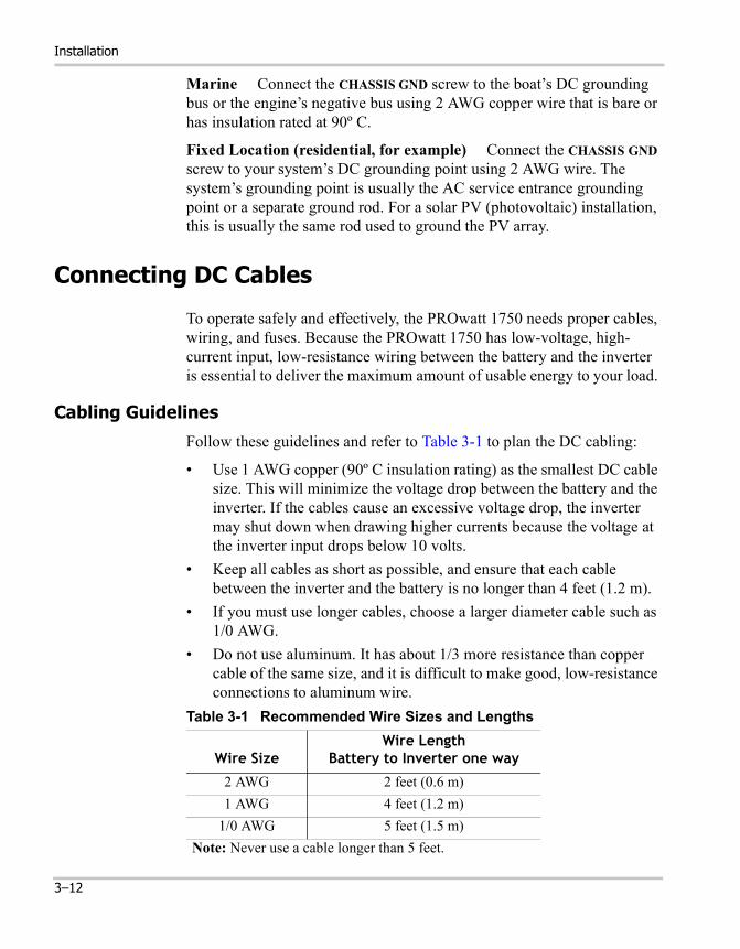
Follow these guidelines and refer to Table 3-1 to plan the DC cabling:
• Use 1 AWG copper (90º C insulation rating) as the smallest DC cable size. This will minimize the voltage drop between the battery and the inverter. If the cables cause an excessive voltage drop, the inverter may shut down when drawing higher currents because the voltage at the inverter input drops below 10 volts.
• Keep all cables as short as possible, and ensure that each cable between the inverter and the battery is no longer than 4 feet (1.2 m).
• If you must use longer cables, choose a larger diameter cable such as 1/0 AWG.
• Do not use aluminum. It has about 1/3 more resistance than copper cable of the same size, and it is difficult to make good, low-resistance connections to aluminum wire.
Table 3-1 Recommended Wire Sizes and Lengths
Wire SizeWire Length
Battery to Inverter one way
2 AWG 2 feet (0.6 m)1 AWG 4 feet (1.2 m)
1/0 AWG 5 feet (1.5 m)Note: Never use a cable longer than 5 feet.
3–12
Connecting DC Cables
Fuse/Circuit Breaker Sizing Guidelines
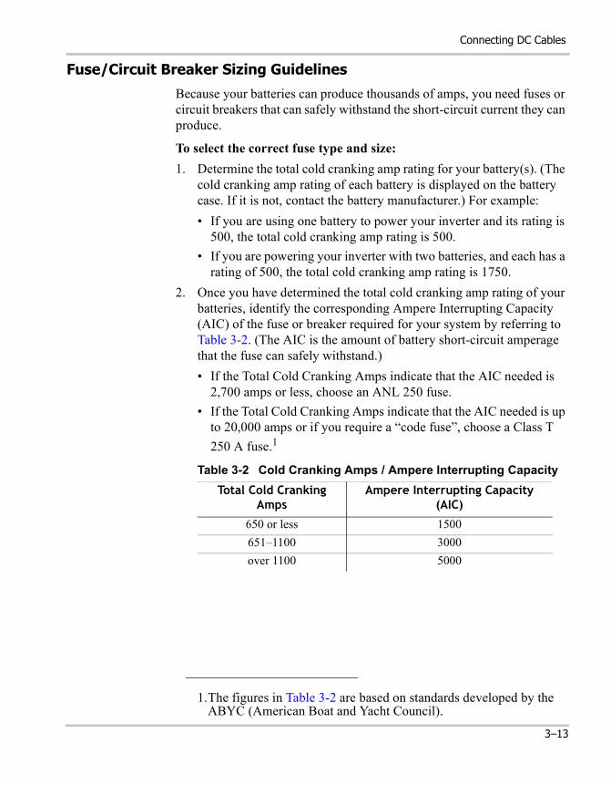
Because your batteries can produce thousands of amps, you need fuses or circuit breakers that can safely withstand the short-circuit current they can produce.
To select the correct fuse type and size:1. Determine the total cold cranking amp rating for your battery(s). (The
cold cranking amp rating of each battery is displayed on the battery case. If it is not, contact the battery manufacturer.) For example:• If you are using one battery to power your inverter and its rating is
500, the total cold cranking amp rating is 500.• If you are powering your inverter with two batteries, and each has a
rating of 500, the total cold cranking amp rating is 1750.2. Once you have determined the total cold cranking amp rating of your
batteries, identify the corresponding Ampere Interrupting Capacity (AIC) of the fuse or breaker required for your system by referring to Table 3-2. (The AIC is the amount of battery short-circuit amperage that the fuse can safely withstand.)• If the Total Cold Cranking Amps indicate that the AIC needed is
2,700 amps or less, choose an ANL 250 fuse.• If the Total Cold Cranking Amps indicate that the AIC needed is up
to 20,000 amps or if you require a “code fuse”, choose a Class T 250 A fuse.1
Table 3-2 Cold Cranking Amps / Ampere Interrupting CapacityTotal Cold Cranking
AmpsAmpere Interrupting Capacity
(AIC)
650 or less 1500651–1100 3000over 1100 5000
1.The figures in Table 3-2 are based on standards developed by the ABYC (American Boat and Yacht Council).
3–13
Installation
Cabling Procedure
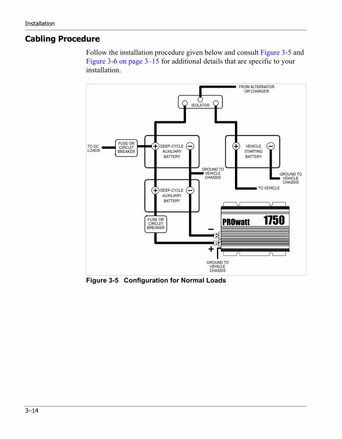
Follow the installation procedure given below and consult Figure 3-5 and Figure 3-6 on page 3–15 for additional details that are specific to your installation.
Figure 3-5 Configuration for Normal Loads
FROM ALTERNATOROR CHARGER
DEEP-CYCLEAUXILIARYBATTERY
VEHICLESTARTINGBATTERY
ISOLATOR
GROUND TOVEHICLECHASSIS
TO VEHICLE
GROUND TOVEHICLECHASSIS
TO DCLOADS
FUSE ORCIRCUIT
BREAKER
DEEP-CYCLEAUXILIARYBATTERY
PROwatt 1750
GROUND TOVEHICLECHASSIS
FUSE ORCIRCUIT
BREAKER
3–14
Connecting DC Cables
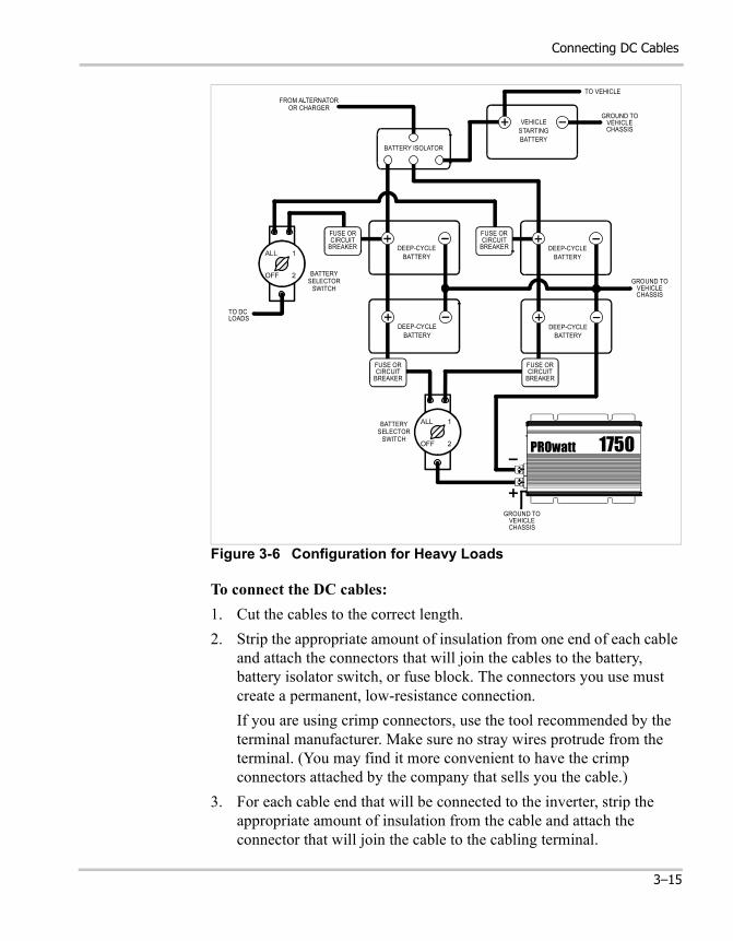
To connect the DC cables:1. Cut the cables to the correct length.2. Strip the appropriate amount of insulation from one end of each cable
and attach the connectors that will join the cables to the battery, battery isolator switch, or fuse block. The connectors you use must create a permanent, low-resistance connection.If you are using crimp connectors, use the tool recommended by the terminal manufacturer. Make sure no stray wires protrude from the terminal. (You may find it more convenient to have the crimp connectors attached by the company that sells you the cable.)
3. For each cable end that will be connected to the inverter, strip the appropriate amount of insulation from the cable and attach the connector that will join the cable to the cabling terminal.
Figure 3-6 Configuration for Heavy Loads
FROM ALTERNATOROR CHARGER
TO VEHICLE
VEHICLESTARTINGBATTERY
DEEP-CYCLEBATTERY
DEEP-CYCLEBATTERY
DEEP-CYCLEBATTERY
DEEP-CYCLEBATTERY
FUSE ORCIRCUIT
BREAKER
FUSE ORCIRCUIT
BREAKER
BATTERYSELECTOR
SWITCH
BATTERY ISOLATOR
BATTERYSELECTOR
SWITCH
TO DCLOADS
PROwatt 1750
GROUND TOVEHICLECHASSIS
GROUND TOVEHICLECHASSIS
GROUND TOVEHICLECHASSIS
ALL
OFF 2
1
ALL
OFF 2
1
FUSE ORCIRCUIT
BREAKER
FUSE ORCIRCUIT
BREAKER
3–15
Installation
4. Install a fuse and fuse holder in the cable that will be used for the positive side of the DC circuit. The fuse must be as close to the battery as possible, be rated for DC circuits, and have an Ampere Interrupting Capacity (AIC) that exceeds the short-circuit current available from the battery. (See “Fuse/Circuit Breaker Sizing Guidelines” on page 3–13.)
5. Slide the two plastic terminal connector covers (boots) over the ends of the cables that will be attached to the inverter (red on positive; black on negative).
6. For each cable, place the cable connector (ring terminal or box lug) on the appropriate cabling terminal on the inverter’s DC end (red on positive; black on negative), and then install the lock washer and nut that are supplied. Tighten the nut to a torque of 9–10 foot pounds (12–13 Nm). See Figure 3-4.
7. Slide the terminal connector covers over the cabling terminals. Slit the underside of the covers if you have trouble fitting them.
8. Attach the connector on the negative cable to the negative battery terminal. Make a secure connection. Loose connectors cause excessive voltage drop and may cause overheated wires and melted insulation.
9. Before proceeding, make sure that the cable you have just installed connects the negative terminal of the inverter to the negative terminal of the battery.
CAUTION: Reverse Polarity
Power connections to the PROwatt 1750 must be positive to positive and negative to negative.
A reverse polarity connection (positive to negative) will blow a fuse in the inverter and may permanently damage the unit. Damage caused by a reverse polarity connection is not covered by your warranty.
WARNING: Explosion or Fire
Do not complete the next step if flammable fumes are present. Explosion or fire may result. Thoroughly ventilate the battery compartment before making this connection.
3–16
Connecting DC Cables
10. Connect the cable from the positive (red) terminal of the PROwatt 1750 to the positive terminal of the battery.This is the last cable connection. A spark is normal when you make it.
11. If you have installed a battery selector switch, use it to select one of the batteries or battery banks.
12. Turn on the inverter’s On/Off switch.13. Check the front panel of the inverter. The VOLTS indicator should read
12–13 volts, depending on the voltage of the battery. If it does not, check your battery and the connection to the inverter. The other indicators should be off.
3–17

3–18
4 Operation
Chapter 4 explains how to operate the PROwatt 1750 most efficiently. Specifically, this chapter:• Gives procedures for operating the inverter
from the front panel and from the remote On/Off switch
• Discusses operating limits• Provides information about routine
maintenance• Discusses battery charging frequency
Operation
Turning the Inverter On and Off
The On/Off switch on the inverter’s front panel turns the control circuit in the PROwatt 1750 on and off.
To turn the inverter on and off from its front panel:• Turn the inverter’s On/Off switch on or off.
When the switch is Off, the inverter draws no current from the battery.
Operating Several Loads at Once
If you are going to operate several loads from the PROwatt 1750, turn them on separately after you have turned the inverter on.
This will ensure that the inverter does not have to deliver the starting current for all the loads at once.
Turning the Inverter Off Between Charges
When the On/Off switch is on but no power is being supplied to a load, the inverter draws less than 500 mA from the battery. This is a low current draw. It would take more than a week to discharge a 100 Ah battery at this current, so you don’t have to worry about excessive drain on your battery if you leave the inverter switched on for a few days.
If you are not planning to recharge your battery within a week or so, switch the inverter off.
CAUTION
The inverter’s On/Off switch does not disconnect power from the PROwatt.
4–2
Using the Remote On/Off Switch
Using the Remote On/Off Switch
To operate the inverter from the remote On/Off switch:1. Turn on the inverter’s On/Off switch.
2. Press the touch control button on the remote switch to turn the inverter on. The INVERTER ON indicator lights up.Press the button again if you want to turn the inverter off. The INVERTER ON indicator goes off.
Testing the GFCI-Protected AC Outlet
The AC outlet on the Prowatt 1750 is a Ground Fault Circuit Interrupter (GFCI) outlet. This protects you against hazardous electrical shocks that could be caused by dampness, faulty mechanism, worn insulation, etc. You might still feel shock, but the GFCI should cut it off quickly enough so an adult in normal health is not seriously injured (infants and small children may still be affected).
Test the GFCI periodically to make sure it is operating correctly.
To test the GFCI protection:1. Turn the inverter on.2. Plug a test lamp into the outlet.3. Push the TEST button.
The RESET button should pop out and the power should turn off (the lamp should go out). If the lamp remains lit, or if the RESET button does not pop out, return the inverter to the place of purchase for service.
If the GFCI trips by itself at any time, reset it and perform the preceding test.
Note: Leave this switch on during operation. Turning it off disables the remote switch.
4–3
Operation
Reading the Front Panel Indicators
Battery Voltage Indicator
The battery VOLTS indicator shows the voltage at the input terminals of the PROwatt 1750. At low input currents, this voltage is very close to the battery voltage. At high input currents, this voltage is lower than the battery voltage because of the voltage drop across the cable and connection.
• During operation, the voltage should remain in the green area.• If voltage goes into the top or bottom red area, the inverter may shut
down.
Battery Current Indicator
The AMPS indicator shows the current that the inverter is drawing from the battery. It does not indicate current drawn by other loads also connected to the battery.
• For long-term operation, the current should remain in the green area.• Short-term operation is possible with the current in the yellow area.• If the current rises to the red area, the inverter reduces its output
voltage to protect itself.
OVER TEMP Indicator
The OVER TEMP LED (light emitting diode) indicates that the inverter has shut itself down because it has overheated. The inverter may overheat because it has been operated at power levels above its continuous output rating, or because it has been installed in a location that does not allow it to dissipate heat properly. The inverter will restart automatically once it has cooled off.
OVER LOAD Indicator
The OVER LOAD LED indicates that the inverter has shut itself down because of severe overload, an AC wiring fault, or another AC voltage source connected to the output.
If the OVER LOAD LED comes on, turn off the On/Off switch, correct the fault condition, and then turn the switch back on.
Do not turn the inverter on again until you have corrected the fault condition.
4–4
Operating Limits
Operating Limits
Power Output
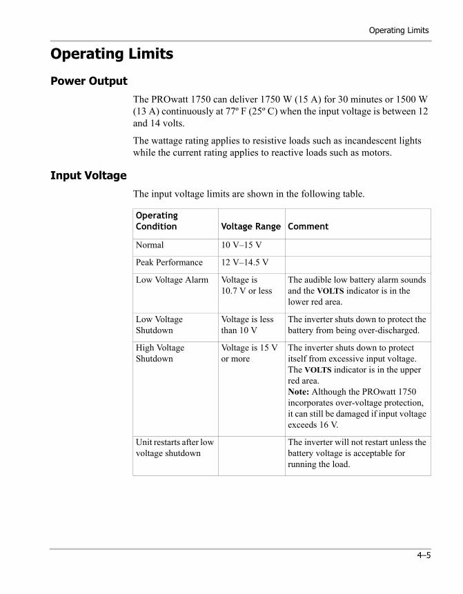
The PROwatt 1750 can deliver 1750 W (15 A) for 30 minutes or 1500 W (13 A) continuously at 77º F (25º C) when the input voltage is between 12 and 14 volts.
The wattage rating applies to resistive loads such as incandescent lights while the current rating applies to reactive loads such as motors.
Input Voltage
The input voltage limits are shown in the following table.
Operating Condition Voltage Range Comment
Normal 10 V–15 V
Peak Performance 12 V–14.5 V
Low Voltage Alarm Voltage is 10.7 V or less
The audible low battery alarm sounds and the VOLTS indicator is in the lower red area.
Low Voltage Shutdown
Voltage is less than 10 V
The inverter shuts down to protect the battery from being over-discharged.
High Voltage Shutdown
Voltage is 15 V or more
The inverter shuts down to protect itself from excessive input voltage. The VOLTS indicator is in the upper red area.Note: Although the PROwatt 1750 incorporates over-voltage protection, it can still be damaged if input voltage exceeds 16 V.
Unit restarts after low voltage shutdown
The inverter will not restart unless the battery voltage is acceptable for running the load.
4–5
Operation
Inverter Loads
The PROwatt 1750 will operate most AC loads within its power rating (1750 watts / 15 amps). However, some appliances and equipment may be difficult to operate, and other appliances may actually be damaged if you try to operate them with the PROwatt 1750. Please read “Problem Loads” and “Trouble Loads” carefully.
Problem Loads
Some induction motors used in freezers, pumps, and other motor-operated equipment need high surge currents to start. The PROwatt 1750 may not be able to start some of these motors even though their rated current draw is within the inverter’s limits. The PROwatt 1750 will normally start single-phase induction motors rated at 3/4 horsepower or less.
If a motor refuses to start, observe the VOLTS indicator while trying to start the motor. If the indicator drops below 11 V while the Prowatt 1750 is trying to start the motor, this may be why the motor won’t start. Make sure that the battery connections are good and that the battery is fully charged. If the connections are good and the battery is charged, but the voltage still drops below 11 V, you may need to use a larger battery.
Trouble Loads
Some appliances, including the types listed below, may be damaged if they are connected to the PROwatt 1750:• Electronics that modulate RF (radio frequency) signals on the AC line
will not work and may be damaged.• Speed controllers found in some fans, kitchen appliances, and other
loads may be damaged.• Some rechargers for small nickel-cadmium batteries can be damaged.
See “Precautions For Using Rechargeable Appliances” on page viii for details.
If you are unsure about powering any device with the PROwatt 1750, contact the manufacturer of the device.
CAUTIONSome equipment may be damaged by the PROwatt 1750’s quasi-square wave output.
4–6
Battery Charging Frequency
Battery Charging Frequency
When possible, recharge your batteries when they are about 50% discharged or earlier. This gives them a much longer life cycle than recharging when they are almost completely discharged. For information about battery chargers, see our web site at www.xantrex.com
Routine Maintenance
Minimal maintenance is required to keep your PROwatt 1750 operating properly. Periodically you should:
• Clean the exterior of the unit with a damp cloth to prevent the accumulation of dust and dirt
• Ensure that the DC cables are secure
4–7

4–8
5 Troubleshooting
Chapter 5 will help you identify the source of most problems that can occur with the PROwatt 1750.If you have a problem with the inverter, please review this chapter before contacting Xantrex Customer Service.If you are unable to solve a problem and need to contact Xantrex, record the information that is asked for in “Information About Your System” on page D–4. This will help our Customer Service Representatives give you better service.

Troubleshooting
Common Problems
Buzz in Audio Equipment
Some inexpensive stereo systems emit a buzzing noise from their loudspeakers when operated from the PROwatt 1750. This occurs because the power supply in the audio system does not adequately filter the modified sine wave produced by the inverter. The only solution is to use a sound system that has a higher quality power supply.
Television Reception
When operating, the PROwatt 1750 can interfere with television reception on some channels. If interference occurs, try the following:
1. Make sure that the chassis ground screw on the rear of the Prowatt 1750 is solidly connected to the ground system of your vehicle, boat, or home.
2. Make sure that the television antenna provides an adequate (“snow-free”) signal and that you are using good quality cable between the antenna and the television.
3. Keep the cables between the battery and the Prowatt 1750 as short as possible and twist them together with two to three twists per foot. (This minimizes radiated interference from the cables.)
4. Move the television as far away from the Prowatt 1750 as possible.5. Do not operate high power loads with the Prowatt 1750 while the
television is on.
5–2
Troubleshooting Reference
Troubleshooting Reference
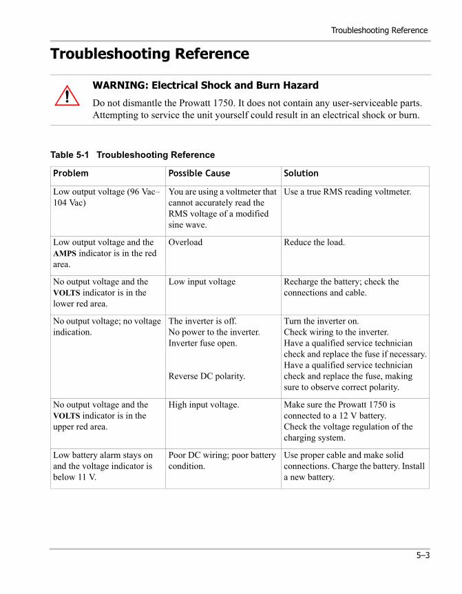
WARNING: Electrical Shock and Burn Hazard
Do not dismantle the Prowatt 1750. It does not contain any user-serviceable parts. Attempting to service the unit yourself could result in an electrical shock or burn.
Table 5-1 Troubleshooting Reference
Problem Possible Cause Solution
Low output voltage (96 Vac–104 Vac)
You are using a voltmeter that cannot accurately read the RMS voltage of a modified sine wave.
Use a true RMS reading voltmeter.
Low output voltage and the AMPS indicator is in the red area.
Overload Reduce the load.
No output voltage and the VOLTS indicator is in the lower red area.
Low input voltage Recharge the battery; check the connections and cable.
No output voltage; no voltage indication.
The inverter is off.No power to the inverter.Inverter fuse open.
Reverse DC polarity.
Turn the inverter on.Check wiring to the inverter.Have a qualified service technician check and replace the fuse if necessary.Have a qualified service technician check and replace the fuse, making sure to observe correct polarity.
No output voltage and the VOLTS indicator is in the upper red area.
High input voltage. Make sure the Prowatt 1750 is connected to a 12 V battery.Check the voltage regulation of the charging system.
Low battery alarm stays on and the voltage indicator is below 11 V.
Poor DC wiring; poor battery condition.
Use proper cable and make solid connections. Charge the battery. Install a new battery.
5–3
Troubleshooting
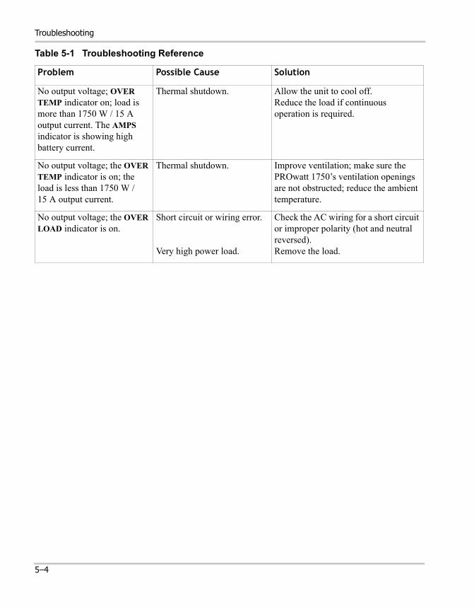
No output voltage; OVER TEMP indicator on; load is more than 1750 W / 15 A output current. The AMPS indicator is showing high battery current.
Thermal shutdown. Allow the unit to cool off.Reduce the load if continuous operation is required.
No output voltage; the OVER TEMP indicator is on; the load is less than 1750 W / 15 A output current.
Thermal shutdown. Improve ventilation; make sure the PROwatt 1750’s ventilation openings are not obstructed; reduce the ambient temperature.
No output voltage; the OVER LOAD indicator is on.
Short circuit or wiring error.
Very high power load.
Check the AC wiring for a short circuit or improper polarity (hot and neutral reversed).Remove the load.
Table 5-1 Troubleshooting Reference
Problem Possible Cause Solution
5–4

A Specifications
Appendix A contains electrical and physical specifications for the PROwatt 1750 and its remote On/Off switch.
Specifications
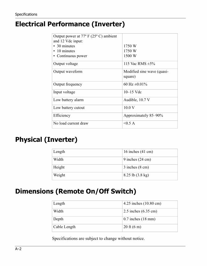
Electrical Performance (Inverter)
Physical (Inverter)
Dimensions (Remote On/Off Switch)
Specifications are subject to change without notice.
Output power at 77º F (25º C) ambient and 12 Vdc input:• 30 minutes• 10 minutes• Continuous power
1750 W1750 W1500 W
Output voltage 115 Vac RMS ±5%
Output waveform Modified sine wave (quasi-square)
Output frequency 60 Hz ±0.01%
Input voltage 10–15 Vdc
Low battery alarm Audible, 10.7 V
Low battery cutout 10.0 V
Efficiency Approximately 85–90%
No load current draw <0.5 A
Length 16 inches (41 cm)
Width 9 inches (24 cm)
Height 3 inches (8 cm)
Weight 8.25 lb (3.8 kg)
Length 4.25 inches (10.80 cm)
Width 2.5 inches (6.35 cm)
Depth 0.7 inches (18 mm)
Cable Length 20 ft (6 m)
A–2

B Battery Types and Sizes
The batteries you use strongly affect the performance of the PROwatt 1750. It is important to connect the inverter to the correct size and type of battery.The information in Appendix B will help you select, connect, and maintain batteries that are most appropriate for your application.
Battery Types and Sizes
Battery Types
Automotive Starting Batteries
The lead-acid battery you are most familiar with is probably the starting battery in your automobile. An automotive starting battery is designed to deliver a large amount of current for a short period of time (so it can start your engine). Only a small portion of the battery’s capacity is used when starting the engine, and it is quickly recharged by the running engine.
This type of battery is not designed for repeated cycles where the battery is almost completely discharged and then recharged. If it is used in this kind of deep discharge service, it will wear out very rapidly.
Deep-Cycle Lead-Acid Batteries
Deep-cycle lead-acid batteries are designed for deep discharge service where they will be repeatedly discharged and recharged. They are marketed for use in recreational vehicles, boats, and electric golf carts—so you may see them referred to as RV batteries, marine batteries, or golf cart batteries.
For most applications of the Prowatt 1750, Xantrex recommends that you use one or more deep-cycle batteries that are separated from the vehicle’s starting battery by a battery isolator.
A battery isolator is a solid-state electronic circuit that allows equipment to be operated from an auxiliary battery without danger of discharging the vehicle’s starting battery. During vehicle operation, the battery isolator automatically directs the charge from the alternator to the battery requiring the charge. Figure B-1 and Figure B-2 show a battery isolator in configurations for normal and heavy-duty loads.
Battery isolators are available at marine and RV dealers and most auto parts stores.
B–2

Battery Size
Battery Size
Importance Battery size or capacity is as important as the battery type for efficient operation of your loads. Xantrex recommends that you purchase as much battery capacity as possible.
Battery Capacity Standards
A number of different standards are used to rate battery energy storage capacity. Automotive and marine starting batteries are normally rated in cranking amps. This is not a relevant rating for continuous loads like an inverter. Deep-cycle batteries use a more suitable rating system, either “amp-hours” (“Ah”) or “reserve capacity” in minutes.
Battery Reserve Capacity Battery reserve capacity is a measure of how long a battery can deliver a certain amount of current—usually 25 amps. For example, a battery with a reserve capacity of 180 minutes can deliver 25 amps for 180 minutes before it is completely discharged.
Amp-hour (Ah) Capacity Amp-hour capacity is a measure of how many amps a battery can deliver for a specified length of time—usually 20 hours. For example, a typical marine or RV battery rated for 100 Ah can deliver 5 amps for 20 hours (5 A x 20 hours = 100 Ah).
This same battery can deliver a higher or lower current for less or more time, limited approximately by the 100 Ah figure (for example, 50 A for 2 hours, or 200 A for 1/2 hour), but usually the capacity figure given is only accurate at the specified rate (20 hours).
To calculate the battery capacity you require, read “Estimating Battery Requirements” on page B–4 and “Battery Sizing Example” on page B–4, and then complete the “Battery Sizing Worksheet” on page B–5.
CAUTIONThe PROwatt 1750 must only be connected to batteries with a nominal output voltage of 12 volts. The PROwatt 1750 will not operate from a 6 volt battery and will be damaged if connected to a 24 volt battery.
B–3

Battery Types and Sizes
Estimating Battery Requirements
To determine how much battery capacity you need:1. Determine how many watts are consumed by each appliance that you
will operate from the PROwatt 1750. You can normally find this on a label on the product. If only the current draw is given, multiply it by 115 to get the power consumption in watts.
2. Estimate how many hours each appliance will be operating each day.3. Calculate the daily watt-hours needed for each appliance.4. Add the total number of watt-hours needed for all the appliances and
multiply it by the number of days between charges.5. Divide the total watt-hours of AC load between charges by 10. This
gives the battery Ah used between charges.6. Double the total Ah used between charges to get the recommended
battery size in Ah.
See the battery sizing example that follows.
Battery Sizing ExampleThis battery sizing example illustrates a typical calculation, assuming an opportunity to charge the batteries every three days.
Appliance(A) Power
Consumption(B) Operating Time per Day
Daily watt-hours needed for this
appliance(= A x B)
TV & VCR 200 W 2 hours 400 Wh
Microwave oven 1400 W 15 min = 1/4 hour 350 Wh
3 lamps, 60 W each 180 W 4 hours 720 Wh
Coffee maker 600 W 15 min = 1/4 hour 150 Wh
Hair dryer 1500 W 6 min = 1/10 hour 150 Wh
Steam iron 700 W 6 min = 1/10 hour 70 Wh
Total daily watt-hours of AC load 1840 Wh
x Number of days between charges 3
= Total watt-hours of AC load between charges 5520 Wh
Battery Ah used between charges (divide by 10) 552 Ah
Recommended Battery Bank Size in Ah (multiply by 2) 1104 Ah
B–4
Estimating Battery Requirements
This example illustrates how quickly your battery needs can escalate. To reduce the required battery size, you can conserve energy by eliminating or reducing the use of some loads or by re-charging more frequently.
When sizing your battery, resist the temptation to skip the last step of this calculation (multiplying by 2). More capacity is better since you will have more reserve capacity, be better able to handle large loads and surge loads, and your battery won't be discharged as deeply. Battery life is directly dependent on how deeply the battery is discharged. The deeper the discharge, the shorter the battery life.
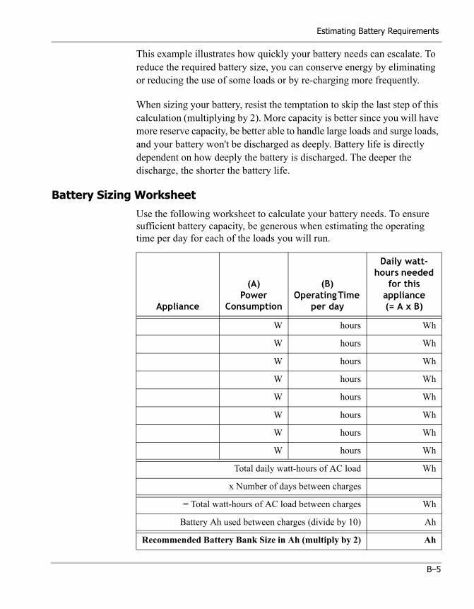
Battery Sizing Worksheet
Use the following worksheet to calculate your battery needs. To ensure sufficient battery capacity, be generous when estimating the operating time per day for each of the loads you will run.
Appliance
(A)Power
Consumption
(B)Operating Time
per day
Daily watt-hours needed
for this appliance(= A x B)
W hours Wh
W hours Wh
W hours Wh
W hours Wh
W hours Wh
W hours Wh
W hours Wh
W hours Wh
Total daily watt-hours of AC load Wh
x Number of days between charges
= Total watt-hours of AC load between charges Wh
Battery Ah used between charges (divide by 10) Ah
Recommended Battery Bank Size in Ah (multiply by 2) Ah
B–5
Battery Types and Sizes
Using Multiple Batteries
As your power requirements increase, you may need to use more than one battery to obtain sufficient capacity. Read “Two Batteries Connected In Parallel” and “Two Separate Battery Banks” to determine whether two batteries or two battery banks are more appropriate for your applications.
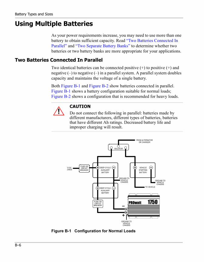
Two Batteries Connected In ParallelTwo identical batteries can be connected positive (+) to positive (+) and negative (–) to negative (–) in a parallel system. A parallel system doubles capacity and maintains the voltage of a single battery.
Both Figure B-1 and Figure B-2 show batteries connected in parallel. Figure B-1 shows a battery configuration suitable for normal loads; Figure B-2 shows a configuration that is recommended for heavy loads.
CAUTIONDo not connect the following in parallel: batteries made by different manufacturers, different types of batteries, batteries that have different Ah ratings. Decreased battery life and improper charging will result.
Figure B-1 Configuration for Normal Loads
FROM ALTERNATOROR CHARGER
DEEP-CYCLEAUXILIARYBATTERY
VEHICLESTARTINGBATTERY
ISOLATOR
GROUND TOVEHICLECHASSIS
TO VEHICLE
GROUND TOVEHICLECHASSIS
TO DCLOADS
FUSE ORCIRCUIT
BREAKER
DEEP-CYCLEAUXILIARYBATTERY
PROwatt 1750
GROUND TOVEHICLECHASSIS
FUSE ORCIRCUIT
BREAKER
B–6
Using Multiple Batteries
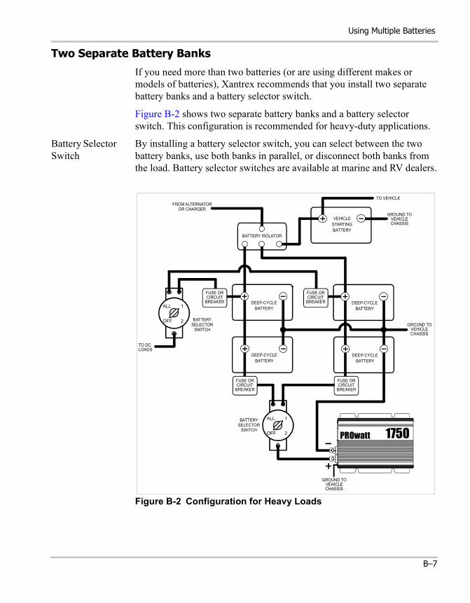
Two Separate Battery Banks
If you need more than two batteries (or are using different makes or models of batteries), Xantrex recommends that you install two separate battery banks and a battery selector switch.
Figure B-2 shows two separate battery banks and a battery selector switch. This configuration is recommended for heavy-duty applications.
Battery Selector Switch
By installing a battery selector switch, you can select between the two battery banks, use both banks in parallel, or disconnect both banks from the load. Battery selector switches are available at marine and RV dealers.
Figure B-2 Configuration for Heavy Loads
FROM ALTERNATOROR CHARGER
TO VEHICLE
VEHICLESTARTINGBATTERY
DEEP-CYCLEBATTERY
DEEP-CYCLEBATTERY
DEEP-CYCLEBATTERY
DEEP-CYCLEBATTERY
FUSE ORCIRCUIT
BREAKER
FUSE ORCIRCUIT
BREAKER
BATTERYSELECTOR
SWITCH
BATTERY ISOLATOR
BATTERYSELECTOR
SWITCH
TO DCLOADS
PROwatt 1750
GROUND TOVEHICLECHASSIS
GROUND TOVEHICLECHASSIS
GROUND TOVEHICLECHASSIS
ALL
OFF 2
1
ALL
OFF 2
1
FUSE ORCIRCUIT
BREAKER
FUSE ORCIRCUIT
BREAKER
B–7
Battery Types and Sizes
Battery Tips
Explosive/Corrosive Gases Lead-acid batteries may emit hydrogen, oxygen, and sulfuric acid fumes when recharging. To reduce the risk of explosion:
• Vent the battery compartment to prevent the accumulation of gases.• Do not install electronic or electrical equipment in the battery
compartment.• Do not smoke or use an open flame when working around batteries.Temperature Sensitivity The capacity of lead-acid batteries is temperature sensitive. Battery capacity is rated at 77º F (25º C). At 0º F (–20º C), the Ah capacity is about half the rated capacity. You should consider temperature when designing your system.
• Low Temperatures If extremely low temperatures are expected where the inverter is going to be located, you should consider a heated equipment room. If the system is located in an unheated space, an insulated battery enclosure is recommended.
• High Temperatures The batteries should also be protected from high temperatures. These can be caused by high ambient temperatures, solar heating of the battery enclosure, or heat released by a nearby engine or generator. High battery temperatures shorten battery life and therefore you should ventilate the enclosure and use shade and insulation as appropriate.
Discharged Batteries Do not leave batteries in a discharged state for more than a day or two. They will undergo a chemical process (sulfation) that can permanently damage the battery. As well, batteries self-discharge over a period of three to six months, so they should be recharged periodically even if they are not being used.
Electrolyte Level If your batteries are not the “maintenance-free” type, check the electrolyte level at least once a month. Excessive fluid loss is a sign of overcharging. Replenish the electrolyte using distilled water only.
WARNING
Review “Precautions When Working With Batteries” on page viii before you work with the batteries in your system.
B–8
Battery Tips
Battery Connections Connections to battery posts must be made with permanent connectors that provide a reliable, low-resistance connection. Do not use alligator clips. Clean the connections regularly and prevent corrosion by using a protective spray coating or vaseline.
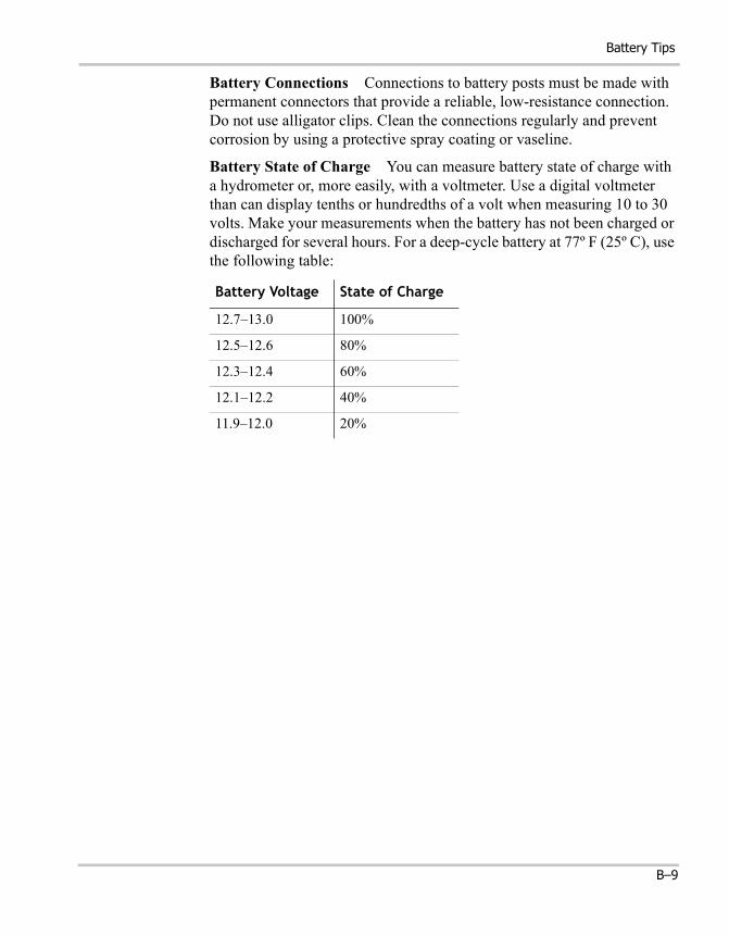
Battery State of Charge You can measure battery state of charge with a hydrometer or, more easily, with a voltmeter. Use a digital voltmeter than can display tenths or hundredths of a volt when measuring 10 to 30 volts. Make your measurements when the battery has not been charged or discharged for several hours. For a deep-cycle battery at 77º F (25º C), use the following table:
Battery Voltage State of Charge
12.7–13.0 100%
12.5–12.6 80%
12.3–12.4 60%
12.1–12.2 40%
11.9–12.0 20%
B–9

B–10

C Alternators and Charging Systems
A good charging system is important for the health of your batteries. Poor recharging methods can quickly damage them.Appendix C provides guidelines for recharging batteries from an alternator, from AC power, and from alternate energy sources.
Alternators and Charging Systems
Charging System Requirements
Your charging system should be capable of delivering a charging current equal to 25% of the amp-hour capacity of your battery. For example, if you have a 200 Ah battery, the charging system should be able to deliver 50 amps. The charging system must also be able to charge each 12 volt battery up to approximately 14.4 V and then drop back to a “float” voltage of 13.5–14 V (or shut off).
Charging With an Engine Alternator
Read the following information to determine whether your vehicle’s standard alternator will be adequate by itself, whether you should install an alternator controller, or whether you need a high-output alternator.
Using a Standard Vehicle Alternator
A typical engine alternator (12 volts) may not be able to meet the requirements outlined above if your system uses large capacity batteries. Alternators are typically rated for the current they can deliver when they are cold. In use, alternators heat up, and their output current capability drops by as much as 25%. Therefore, standard alternators with ratings of 40–105 amps only deliver a maximum of 30–80 amps in actual use and deliver even less as battery voltage rises. Many alternators cannot produce more than 13.6 volts when they are hot. As a result, a standard alternator may not be able to charge a large battery quickly and completely.
Two solutions are to install an alternator controller or to install a high-output alternator.
CAUTION
Never operate the PROwatt 1750 directly from an alternator. To work properly, the inverter must be connected to a battery or a well-regulated, high-current DC power supply.
C–2
Charging From AC Power
Using an Alternator Controller
If your regular alternator is inadequate by itself, you can install an alternator controller that bypasses the voltage regulator and boosts the alternator’s output voltage during charging. This will increase the alternator’s charging rate at higher battery voltages and ensure more rapid and complete charging.
Alternator controllers are available from marine product dealers.
Using a High-Output Alternator
Heavy-duty alternators rated from 100–140 A can replace standard alternators and produce the higher current and voltage required to charge multiple battery systems. They are available from RV and marine dealers as well as auto parts suppliers.
Charging From AC Power
When recharging from AC power, use a good quality marine battery charger or RV converter that meets the requirements outlined in “Charging System Requirements” on page C–2. For information about battery chargers, visit our web site at www.xantrex.com
Do not use chargers intended for occasional recharging of automotive starting batteries. These chargers are not intended for continuous use.
Charging From Alternative Energy Sources
You can also charge your batteries from alternative energy sources such as solar panels, wind, or hydro systems. Make sure you use the appropriate battery charge controller for your particular energy source.
CAUTION
Never operate the Prowatt 1750 directly from an energy source such as a solar panel. The inverter must be connected to a battery or a well-regulated, high-current DC power supply to work properly.
C–3

C–4

D Product and System Information
Appendix D contains the warranty for your Prowatt 1750 as well as instructions for returning the product for servicing.Appendix D also has a place where you can record information about your system in case you need to contact Customer Service.

Product and System Information
WarrantyWhat does this warranty cover? Xantrex manufactures its products from parts and components that are new or equivalent to new, in accordance with industry-standard practices. This warranty covers any defects in workmanship or materials.
How long does the coverage last? This warranty lasts for twelve months from the date of purchase. Implied warranties of merchantability and fitness for a particular purpose are limited to twelve months from the date of purchase. Some jurisdictions do not allow limitations on how long an implied warranty lasts, so the above limitation may not apply to you.
What does this warranty not cover? This warranty will not apply where the product has been misused, neglected, improperly installed, physically damaged or altered, either internally or externally, or damaged from improper use or use in an unsuitable environment. Xantrex does not warrant uninterrupted operation of its products. Xantrex shall not be liable for damages, whether direct, incidental, special, or consequential, or economic loss even though caused by the negligence or fault of Xantrex. Some jurisdictions do not allow the exclusion or limitation of incidental or consequential damages, so the above limitation or exclusion may not apply to you.
What will Xantrex do? Xantrex will, at its option, repair or replace the defective product free of charge. Xantrex will, at its own option, use new and/or reconditioned parts made by various manufacturers in performing warranty repair and building replacement products. If Xantrex repairs or replaces a product, its warranty term is not extended. Xantrex owns all parts removed from repaired products.
How do you get service? To qualify for the warranty, dated proof of purchase must be provided and the product must not be disassembled or modified without prior authorization by Xantrex. If your product requires warranty service, please return it to the place of purchase along with a copy of your dated proof of purchase. If you are unable to contact your merchant, or the merchant is unable to provide service, contact Xantrex directly at:
Phone: 1-800-670-0707Fax: 1-800-994-7828Email: [email protected]
D–2
Return Material Authorization Policy
Return Material Authorization PolicyYou must obtain a Return Material Authorization (RMA) number from Xantrex before returning a product directly to Xantrex. Products returned without an RMA number or shipped collect will be refused. When you contact Xantrex to obtain service, be prepared to supply:
• The serial number of your product• Its date of purchase• Information about the installation and use of the unit
Record these details in “Information About Your System” on page D–4.
Return Material ProcedureIf you are returning a product from the USA or Canada, follow this procedure:
1. Contact Xantrex to obtain an RMA number and a shipping address.2. Package the unit safely, preferably using the original box and packing
materials. Include the following:• The RMA number supplied by Xantrex• A copy of your dated proof of purchase• A return address where the repaired unit can be shipped• A contact telephone number• A brief description of the problem
3. Ship the unit freight prepaid to the address provided in step 1. Collect shipments will be refused.
How do other laws apply? This warranty gives you specific legal rights, and you may also have other rights which vary from jurisdiction to jurisdiction.
For our Canadian customers: When used herein “implied warranties of merchantability and fitness for a particular purpose” includes all warranties and conditions, express or implied, statutory or otherwise, including without limitation implied warranties and conditions of merchantability and fitness for a particular purpose.
D–3
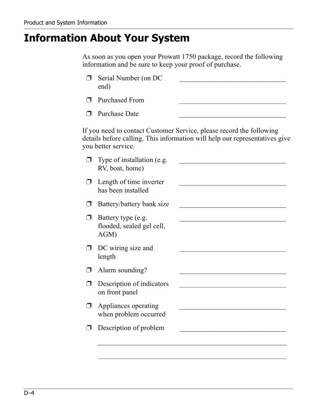
Product and System Information
Information About Your System
As soon as you open your Prowatt 1750 package, record the following information and be sure to keep your proof of purchase.
If you need to contact Customer Service, please record the following details before calling. This information will help our representatives give you better service.
❐ Serial Number (on DC end)
______________________________
❐ Purchased From ______________________________
❐ Purchase Date ______________________________
❐ Type of installation (e.g. RV, boat, home)
______________________________
❐ Length of time inverter has been installed
______________________________
❐ Battery/battery bank size ______________________________
❐ Battery type (e.g. flooded, sealed gel cell, AGM)
______________________________
❐ DC wiring size and length
______________________________
❐ Alarm sounding? ______________________________
❐ Description of indicators on front panel
______________________________
❐ Appliances operating when problem occurred
______________________________
❐ Description of problem ______________________________
_____________________________________________________
_____________________________________________________
D–4
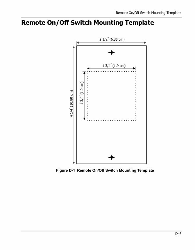
Remote On/Off Switch Mounting Template
Remote On/Off Switch Mounting Template
Figure D-1 Remote On/Off Switch Mounting Template
2 1/2″ (6.35 cm)
4 1/
4″ (10.
80 c
m)
1 3/4″ (1.9 cm)
1 3/
4″ (1.9
cm
)
D–5

D–6

Index
AABYC (American Boat and 3–13AC GND 3–7AC HOT 3–7AC NEUT 3–7AC wiring
color coding 3–6connecting to existing circuit 3–6, 3–7knockout for 2–4procedure 3–7terminal blocks 2–4, 3–7, 3–8
Ah. See amp-hour capacity.air compressors 1–2air conditioners 1–2alarm, low battery 1–3, 4–5, 5–3alternator
high-output 3–3, C–3vehicle alternator C–2
alternator controller 3–3described C–3installing C–3
ampere interrupting capacity 3–13, 3–16amp-hour (Ah) capacity B–3AMPS indicator 2–3, 4–4, 5–3, 5–4appliances
air conditioners 1–2battery-operated 1–viiicurrent draw B–4fans 4–6possible damage to 4–6power consumption B–4, B–5rechargeable 1–viiitelevisions 1–2VCRs 1–2
audio equipment, buzz in 5–2
Bbatteries
amp-hour (Ah) capacity B–3automotive starting B–2, B–3charging frequency 4–7cold cranking amp rating 3–13connecting 2 in parallel B–6deep-cycle lead-acid B–2depth of discharge B–5discharged B–8electrolyte level B–8golf cart B–2marine B–2nickel-cadmium viii, 4–6parallel connection illustrated B–6reserve capacity B–3, B–5routine maintenance 4–7RV B–2self-discharge B–8temperature sensitivity B–8using 2 battery banks B–7using multiple B–6
battery banksdescribed B–7illustrated B–7
battery chargers 4–7for nickel-cadmium batteries 1–viiirecommended types C–3
battery connections B–9battery demand, standby 1–2, 4–2, A–2battery isolator
component 3–3using B–2
battery reserve capacity B–3battery selector switch 3–17, B–7battery size
estimating example B–4
Index
estimating worksheet B–5estimating your needs 3–4, B–3, B–4
Ccable clamp 3–3, 3–7cables. See DC cables.charging
from AC power C–3from alternative energy sources C–3with engine alternator C–2
charging frequency for batteries 4–7charging systems
designing a system 3–4, C–2requirements C–2
chassis groundfor fixed locations 3–12for marine installations 3–12for photovoltaic (PV) installations 3–12for recreational vehicles 3–11guidelines for connecting 3–11
chassis ground screw 2–4, 3–11communications cable
described 2–5extending length 3–10in materials list 2–2maximum length 3–10
current draw, no load 1–2, 4–2, A–2Customer Service
email 2–2, D–2fax number 2–2, D–2phone number 2–2, D–2preparing to call D–4
DDC cables
avoiding excessive lengths 3–5correct polarity 3–16guidelines for selecting 3–12procedure for connecting 3–14recommended diameter and length 3–12
DC cabling terminals 2–4depth of discharge (DOD) B–5
Index–2
Eelectrolyte level B–8explosive gases vii, 3–16, B–8
Ffreezers 4–6fuses 3–3, 3–13
ampere interrupting capacity (AIC) 3–13, 3–16ANL 250 3–13Class T 250 A 3–13replacing 5–3type and size 3–13
Ggases
battery, venting 3–5explosive vii, 3–16, B–8
GFCI protection 1–3, 2–3, 4–3GFCI testing 4–3
Hhigh-output alternator
described C–3installing C–3mention 3–3
hydrometer B–9
Iindicators
AMPS 2–3, 4–4, 5–3, 5–4how to read 4–4INVERTER ON 2–5, 4–3OVER LOAD 2–3, 4–4, 5–4OVER TEMP 2–3, 4–4, 5–4VOLTS 2–3, 3–17, 4–4, 5–3
input voltage 4–5installation
codes 3–2, 3–11materials 3–2overview of steps 3–3
Index
planning 3–4tools 3–2
inverterback panel features described 2–4back panel illustrated 2–4connecting to existing AC circuit 3–6, 3–7date of purchase D–3electrical specifications A–2front panel features described 2–3front panel illustrated 2–3input voltage 4–5loads 4–6mounting location 3–5, 3–10mounting orientation 3–10operating several loads 4–2physical specifications A–2power output 4–5problem loads 4–6proof of purchase D–2purchase date D–4serial number D–3, D–4trouble loads 4–6turning off 4–2turning on 4–2
INVERTER ON indicator 2–5, 4–3
Jjack, to connect remote On/Off switch 2–3
Lloads
chargers 4–6electronics 4–6fans 4–6high-power consumption 3–6problem 4–6reactive 4–5resistive 4–5speed controllers 4–6trouble 4–6
low battery alarm 4–5, 5–3
Mmaterials list for PROwatt 1750 2–2motors
difficulty starting 4–6induction 4–6
mounting location 3–5mounting orientation 3–10
NNational Electrical Code requirements 3–11nickel-cadmium batteries viii, 4–6
OOn/Off switch (front panel)
illustration and description 2–3using 4–2
On/Off switch (remote)description 2–5illustrated 2–5installation procedure 3–10mounting template illustrated D–5operating inverter from 4–3part of materials list 2–2specifications A–2using 4–3
output voltage low 5–3OVER LOAD indicator 2–3, 4–4, 5–4OVER TEMP indicator 2–3, 4–4, 5–4
Ppolarity, correct 3–6, 3–7, 3–16, 5–3polarity, incorrect 5–4power output 4–5power tools 1–2power tools, battery-operated 1–viiiprecautions
explosive gas viiwhen using rechargeable appliances 1–viiiwhen working with batteries viii
product information, recording 2–2
Index–3

Index
proof of purchase D–2, D–4pumps 4–6purchase date D–4
Rreserve capacity B–3restart after shutdown 4–5Return Material Authorization number D–3returning products
how to package D–3policy D–3procedure D–3
Ssafety information vii, 3–2serial number D–3, D–4servicing
no user-serviceable parts 1–vii, 5–3obtaining service 2–2
shipping address D–3shutdown
from AC overload 1–3, 4–4from high or low voltage 1–3, 4–4from high temperature 1–3, 4–4restart after 4–5
specificationsinverter A–2remote On/Off switch A–2
starting batteries B–3state of charge B–9
Ttelevision reception 5–2televisions 1–2temperature
ideal ambient temperature 3–5reducing ambient temperature 5–4
template (remote switch)illustrated D–5installing 3–10
Index–4
terminal blocksAC GND 3–7AC HOT 3–7AC NEUT 3–7for AC wiring 2–4, 3–7, 3–8
transfer switch (AC)illustrated 3–9in materials list 3–3installing 3–8
transfer switching 3–6troubleshooting
buzz in audio equipment 5–2common problems 5–2reference table 5–3television reception 5–2
VVCRs 1–2ventilation vii, viii, 3–5, 5–4, B–8ventilation openings 2–4, 3–10, 5–4voltmeter B–9VOLTS indicator 2–3, 3–17, 4–4, 5–3
Wwarranty
and damage caused by 3–7, 3–16obtaining service D–2period of coverage D–2terms and conditions D–2
web site v, 4–7, C–3wiring. See AC wiring or DC cables.
XXantrex
email 2–2, D–2fax number 2–2, D–2phone number 2–2, D–2web site v, 4–7, C–3