xatioxal advisory commi!?tee for … · tiicez?ical notes xatioxal advisory commi!?tee for...
TRANSCRIPT

4
-.‘i.-
.
—. —.. . . ..—
——. ... —-
TIICEZ?ICAL NOTES
XATIOXAL ADVISORY COMMI!?TEE FOR AERONAUTICS
,(”
.
.
No. 820
..CA-
-.
. g\
s
THE AERODYHAXICS OF A WIKD-TUIWEL I’M.
By 31ake W. Corson$ Jr.Langley Menorial Aeronautical Laboratoryp p- q ?+m.~
:........=--,--:=
WashingtonAugust 1941
,
. ..? -- “=---’.-..5 r-. 3..4..- -.— .
.,,.1 - -..—
https://ntrs.nasa.gov/search.jsp?R=19930085187 2018-05-29T13:49:53+00:00Z

*,
“~
NATIONAL ADVISORY COMMITTEE FOR AERONAUTICS
TJ$CHNICAL NOTE NO. 820
THE AERODYNAMICS OF A WIND-TUNNEL FAN
By Blake W. Corson, Jr.
SUMMARY
The vortex %lade-element theory modified to apply toan axial fan working in a duct is reviewed, Thrust andpower coefficients for a fan are identified with the cor-responding coefficients for airplane propellers. Tho re-lation of prossuro producod by th? fan to the blade-elementcoefficients Is developed. The distribution of axial ve-locity of fluid through a fan Is assumed to he controlledby the fan itself. The radial distribution of tangentialvelocity imported by tho fan to fluid moving through thefan is shown to bo~indopendent of the axial-velocity dis-tribution.
A nondimensional coefficient, designated the rotationconstant, is introduced. This constant is based solelyupon design information. The use of the rotation constantin simplifying the design of a fan for a specific operat-ing condition is demonstrated. Based on the use of therotation constant, a graphical method ~s outlined by whichthe performance of a given fan in a given wind tunnel maybe predicted and ~y,which the .distributions of axial voloc-
.-
ity of the fluid through the fan under various oporatingconditions may bo established.
..., .:.,INTRODUCTION
--
...,
Comprehensive; tireatment .of factors bearing on the op-eration of axial fans have been made by several investi-gatt3rs. Following customary pro,cedure, ”each, investigatorassumed that the axial velocity of fluid through the fanwas uniform. Ignoring viscous distortion of the velocitydistribution, this assu.rnption is logical for the designcondition but may n“ot, of necessity, hold for all operat-ing conditions. Radially nonuniform axial velccity undersome operating conditions. is mentioned in roforonce 1,Porforrnanco estimation fora fan that must work ovor a
—...—

2 , NA CA....
range of operatingcedure which takes
Tqchni,cal Noto ~To. 820,..
conditions can Fe made only by some pro-account of the interrelation of axial
velocity and torque distributions
v
This paper deals only with the aerodynamics of thefan proper and dem?~strates the manner in.which the. radialdistribution of axial velocity of--fluid through a fan isgoverned. %y the geometry of the fan itself. Although SpO-cial reference is made to a wind-tunnel fan, the conclu.sions arrived at here apply to any single-stage fan work-ing in a close duct. Some of the derivations pu%lishod intho reforoncos aro ropeatod here, but a consistent notationis used to coordinate tho work of various authors. Thovortox blado-olombfit theory znodifiod to apply to a fan”work-ing in a duct is dov~lopod, A direct jrocodure is i,ndi-
catod for design of the optimum fan for a given combina-tion of mass flow, ,shaft speed, power, and fan dianeter.A relation is established between elemental torque coef!fi-
ciont, axial vel’oc$’ty, radius,.
and a rotation constantC .
Based. on this rela’tion, a method is giv”on by which porform- yante charts for a’,fiinmay bo prepared.
.,,,. ,9
SYMBOLS... .
,’
D diamotor of fan ‘.. .’
Do hub-housing diame’t’er,..
r radius of,any blade element under consideration,..
ro hub-housing riictitis., ..,... 1 ..
n shaft speedt revolutions per second
v axial velocity of fluid thTough fan
,W angu~,a.r.pyp.l,oc.i.tyimparte,~ to fluid. by fan .,!. .,.,.,.. . .,.
w’= wr, tangkritia~ vol”ocity at radius r iizp~rted’“to’.,,, fluid by f,~n ... .. . .-“
,. .
Vf final vQl,ocity .of air..:a:~$,&r””lOaving fan;’ +oc:o,r sum’of ...V and “w
,. ...... ..-.“f .“,,...’, ,-.,.”. ....,I
.
.
\,-
‘R velocity of fluid .,re’l~t’i,ti~e”td”blade elei.ae”nt;vectorsum o.f (V + %~.n “- w/2) ,-. .

P-●
✎
.
J
Jt
9
P
P.
a
b
h
B
L
CL
D
R
7
P
Q
Qc
Qc 1
CQ
NACA Technical,:lTote.lio. 820 3
slip function (V/nD) , significant only when basedon uniform axial velocity
slip function %ased OR axial velocity at a radius r
helix angle = tan-l —(2nrrtV- w/2)
blade angle
reference blade angle
angle of attack = @ - ~
blade width, or chord
airfoil SeCtiOZ3 thickness
number of blades
lift
lift coefficient
drag
resultant force, vector sum of L+D
tan-l D L/
mass density of air, slugs per cu%fc foot
torque
(p,%.)torque coefficient -
olemontal torque coefficient
0.5
BJ’;’W)=QCo
(~nQD5)torque coefficient —2
—

IT40A
elemental torqu
Technical
,e coeffic5
Not
.ent
e No ● 820
o
3f“r.
fan
5
CQ
/D
d CQI
P i npu t to
Cp power coeffici t (217CQen
T thrust , sha,ft tension
Tc thrust coefficient (*)Tcl elem ental thrus t coe ffi
o.
“.[‘o
cient
5
Tcl d
/D()r5=3 Tc
thrust coefficient (pn:.1)4).—elemental thr‘us
B
t ,effi
5
CT!
/D
Ci
d
ent
()$
-.
= crJ
ofile ef-ficien Cy
rotational efficiency
fan efficiency
mass flow through fan
(
Protation constant —
(nD)aB’M) .

NACA Technical, i?ote Ko. 820 ?5
..
,.
.
E
A
P
~~
A
c,
( 3 ATenergy ratio of wind tunnel
* PT VT
. P )
fan wind-tunnel constant (defined in appendix D)
static-press-are increment across fan
dynamic pressure due to rotational component of veloc.ity downstream from fan
area
c13 Ca, etc. constants
Subscripts:
E fan
T throat
Primed symbols refer to blade elomonts.
BLADE-ELEME?J?T THEORY
A vector diagram of forces and velocities acting on ablade element is shown in figure 1. The element is a se’c-tion of a fan blade at radius r and is of area b X dr.The rotational interference velocity, designated al (~rn)in reference 2, is assumed in this derivation to be T/2,one-half of the final rotational velocity imparted to theannulus of air by B blade elements at radius r, Thisassum~tion is used in references 1 and 30 The inflow ve-locity, av in reference 2, for a fan working in a ductis assumed to be zero. The torque, power, and thrustcharacteristics derived here ’are expressed as coefficientsidentical with tho propoll~r characteristics defined inroforonco 2.
..
dL
[
CL (b/D)dR=— =pVaD~”
Cos Y ] ()isin’$cosyd~

6 NACA Tuchn-teal;:.?Jo’:to”ITo* 820
For ono blado
dR =()
PVa D2K d;””
l?or B blades,
Define
Q&-~; sin (q -1-7) (1)
dQ = P V2 D3,()
BQcld!j
In a later analysis the axial velocity will be con-sidered nonuniform. Since over-all thrust and torque areobtained by integration along the radius of the elemental
, thrusts and torques, velocity varying with radius must re-main under tfi.ointegral sign. It is better, thoreforo, touse coofficionts that includo tho axial volocityc
dQ=Pn2D53Qc~GY ‘G)
..
(2),, “
0.5
Q = P n= D5 BJ%”(O :r. /D
Q =.P n2 D5 CQ
,..
.
(3)

NACA Technical l~oto No, 820 ‘
4
.
,“
Similarly for thrust f,or one blade,
dT = dR COS (@ + y)
Yor 3 blades,.
Define
. .
.“
dT=PVa D23Kcos(@+’Y)d@
Tc I =Kcos(@+Y)
dT =()
PVa Da BTcldrE
=Pn2 D* 3 Tcl (35)2 d (;)
=P 312 G)D4BCTtdr
q = p =2 D4 ~ ~5cTt d (;)
ro/13
T =Pn2D4CT .,. .
The cfficioncy of a blade elomont,
Tr =
., ,.,,
... -. .’T)’=
dT V-” ...-.
2trn“dQ. .
“v’
2rrrn tan (~,+ ‘Y),..
,.1 [~ - (s%) “’l
tan(@ +7)” *rm-~ J “’
,. ,.“l- (
,.Tf y’~.:: w/2
tan (~ + ?) )(2mm - ,~:~ 2vrn ). . . ‘..,..”:..”
,“ .,. . .
-“”.
---u 4:”>“-
(4)
(5)
(6)
(7) _. .
——

NACA Technical Note No..82O ‘
(8)
(In appendix A the factor 1 - L)W2 is shown to rep-21-rrn ~
resent the rotational efficiency of thee~blade element.
The ratio —~tan (~ + W
represents the profile efficiency
and is the expression arrived at by simple blade-elementtheory.
I?RYJSSURE RELATIONS,..
Consider a fan unit working in a closely fitting cyl-indrical duct and moving’s nonviscous incompressible fluid,Limit the length of the cylindrical portion of the duct toa short distance on each sido of the fan and lot the ductto$minato in infinitely ~~rgo conos oxpandiag upstream anddownstream. In order to avoid having to deal with rotationof the fluid, regard tho fan as an actuator disk. Tho as-sumption of incomprossiblo flow d.omands that thoro be nodiscontinuity of axial velocity at the fan. Useful energyimparted to the flow by the fan, therefore, must appear asincrease in static pressure.
At a distance upstream where the velocity of flow isnegligibly small, pressure energy in the fluid is entirelystatic pressure and is equal to the total pressure., Inas-much as there can be no pressure gradient in ~otionl~ss
flow (if gravity is ignored) the total pressure is con-stant for all streamlines, By Bernoulli”ls .ti~eorem the to-tal pressure is constant along any one streamline; hence,the total pressure is constant thro-~hout the flow at allpoints upstream from the fan. The same reasoning can beapplied to show that the total prossuro is”constantthroughout the flow downstream from the fan. It then fol-lows that the increment in total pressure across the fanmust be constant o’v”erthe. entir”e fan disk and must appearonly as an increase in,.s-taticpressurd; . .
.. . .
The fact that the static-pressure increment acrossthe fan is constant over the disk places no restrictionson the distribtit.i~n of s.tat.ic,pressure and axial velocity,which is governed by the relativo amounts of work beingdono by various rogionq of tbti fan, Zf tho tip portion oftho fan is working harder than tho portion near tho hub.
.
.
,

NACA Technical Note No, 820 9
.
I
.
:4
an axial velocity greater than the mean is induced throughthe region of the tip and is accompanied by corresponding-ly lower static pressure in that region on both sides of’the propeller disk. The portion near tho hub, doing rel-atively less work, cannot maintain an axial velocity asgroat as the moan; consequently, highor static prossuroson bot’h sides of the propoller disk exist in this region.Tho static-pressure incromont across tho fan, however, iseverywhere tho same and the axial velocity through anyregion is directly proportional to the relativo amount of~ork being done by that portion of the fan.
In the design of a fan, the distribution of axialvelocity must be assmned and is often regarded as uniform-If diameter and shaft speed are known, the optimum fan canbe designed for the given value of J? Whenever the fanis required to work at a valuo of J other than the due-”sign value, some portion of tho fan is forcod to do rela-tively more work than another and a nonuniform axial-velocity distribution results. Aerodynamic chnracter5.s-tics of the fan, therefore, cannot %0 predicted %Y theassumption of a uniform axial-velocity distribution underall operating conditions.
The conclusion that a constant static-pressure incre-ment exists over the entire propeller disk was based onthe assumption that no rotation was imparted to the fluidas it passed through the fan. Consider a single fan, with-out counterpanes. If the fact is acknowledged that “the”torque driving the fan reacts only on the fluid and thatthe fan does impart rotation to the fluid, then account-must bo taken of variation in tho static-prossuro incre-ment across the fan disk, due to centrifugal pressure.The axial velocity of a fluid particle (in incompressibleflow) is not changed during passage of the particle throughthe fan. The absolute velocity of the fluid particle,however, is increased because of tho rotational velocityimparted to it by tho f~n. Snsopara%lo from this rotationis an accompanying centrifugal pressure dovnistream fromthe fan, which is manifest as static pressure- The “cent-rifugal pressure increases radially from hub housing toduct wall and at any radius is equal to the integratedcentrifugal pressure increments from the hub housing tothat radius. It is now apparent that the fan imparts en-ergy to the fluid as an increase both in- static pressureand in absoluto dynamic pressure and that tho static-prossuro increment being partly centrifugal cannot be con-stant over tho ontiro fan, Investigation of tho distri-
L
10 NACA Technical: l’$o}pe-,~o.820,.. ”-”....<.J.:..-
●
hu,t$on of ,these pressure increments over, the, fan. disk isnow ‘in order, The flow patternj %“ein& assurnbd symmkt”rical
‘about .tlibj-fan axis, iti+estigat,ion aa~- 30’ con”fiiod’”t’o“apiano’ through tho axis’ in the’-re~io’n ‘Kbtwodn tho htib’h~~s-ing .~+~,dybt” wall. ($0.U f,ig’.’”2.’) ● : ~ “. . : ,.””,. ....“,,’.. . .. ..... .:”----‘.. . ..: .“:
... ,., ‘Th:b:only.’’’radialvariation of. the st.atic-”presiure” ln-‘c’renie”nt“through the fan is the variation of tke centrifu-“’gal-’pre”i”sure; k-ence the static~pr”d’ssur~ “g!ra”diobt“is theceht’rtfuga’l-pressure gradient, which ‘is : ““ “...,...
dp— = pwardr
,.”dp = Piu2r dr” ~ . . .
Tha blade-element theory, equation (5), shows theprossuro at radius r to %0
If equations (1) and (4) are combined and K is eliminated,expressions for Tct and p can, he obtained
.Qc’Tel, =
$ tan. ‘(~ +- ‘Y) ,“.“
..- .,
~v2,~”Qcf ..P= “
()
a“-:- ‘““-” (lo)
,’ 21-f “~ . tan (.@ +.yj” ““ ,. - ,.. .-. , .,.,, . .... .
,.Inasmuch-as, t-he .g.~ii~en{ of.pressure ino,rement is
given as a function ot.-thq .an,gular,velocity imparted tothe fluid by the fan~ it would be useful, to.know the pres-sure increment ~in tqrms of tho same parame,tor. The torque
. .
.,. .
..
.>
.-.“. . .
NACA ~echnical Note No. 820 11
.
requtred to impart. angular velocity w to an annulus offluid at radius r is given W _
dQ = 2mr dr Wrwr
By blade-element theory,
dQ=PVa
() (D)PvaD3B. Qc!d ; =~pL)3 =2 ()Wr d ~
r2
()Qct V3=2TT3 wr
Qc’ V Bwr = —=W
()
a (11)
2Tr~
If the values in equation (11) are substituted inequation (10), the pressure increment is expressed as afunction of angular velocity and radius-
“pYwr.... . _
P= ta~ (~ + 7)
.,t . .
~wr p++)’” ‘.. . ‘- . , 7 “ “.
,,
P ““.=
:-titan (q + Y)L(, ) 1
*rn . ~ i,,,.2. ,. “..,...4...,:.,:... .....- ,.....
:.,., .” ‘-,”.”; -w-=’”:P“%u r. ,- ( )2rrrn - ‘$ - :.tan:.@. -. ...‘:tan.($i.+m”.”” :-.- ..,. . . ..” . . . . . .
. . . . . . . . . . . . . .
.. . . . . .
p f= pWr2 ( )%fn-’~ Tjol’ ‘“” ‘“
..>-
, ‘“
. ..,.: . ● ✍ ✎✎✎✎✍ ✎ ✎✎✎✎✎ ✎✌✎ ✎ ..”-
It is not feasible to express the profile efficiency qs afunction of either of the independent variables in equti-.tion (12). The profile efficiency may be assumed to beunity (that is, 7 = 0°) without introducing much error,In order to determine the extent of its influence, however,profile efficiency will be retained and regarded as a con-stant.
12 NAM Technical Noto Ko. 820
The differential of pressure increment, from” equation(12),. is
dp=~olp ~r’ (- %) + (z~~
dp = To ‘ P (- ‘~dw ,:+%nWWdr
. .
dp =(
~o\.P r - rwdu) + %nuiir
If dp is eliminat~d between
.:, ,,
-L& )( )],,.
2~2umdr + radw
+ 2rrnra dw.-wa rdr w 2.dw)““’”T ‘“
.,.,
+ 2?mrdw - w2dr).
(13)
equations (9) and (13),
(Wa dr = ~ot - wrdw + &nwdr + 2nnrdw - W2 dr)
(14)
The steps followed in solv,ing equation (14) are givenin appendi~ B; the solution is stated .in the followingequation:
., 1-TO
“w ( acj 1+-%r.2- =. c —. w
2rrn l+qo )=’(15)
Observation will show that, for r6a-80nable values of w,
1-%.
( ao l-lqon, and Vo, the ftinotion — - ...
I+mo ‘),ie always
. . . 2nn j,:“
nearly equal to Unity. The error introduced by assumingperfect profile efficiency is much less than 1 -.“.,. To. Thesimplifying-~~ij$ti~.~tl’ofi.tliat 7 = 0° made in references 1and 3 is found” ~usti’fiab~”e for equation (15) and will be
~used here; therefore. ra —#n
is a consta,ptg The expres-
sion %m is a constant” for all radii.. . .. . . : ,..,. .,
,.,, ‘#w “ ,? “’5’1 . . ..... ‘ (1s).. ‘“..,... .’”. L,.“..“.“ ,,~ . . - :. “.‘,-’~:(l7)
, . .,’..’:,.,
?w = -
r~ . ; : ,- : .-.:”8:”.”-:... :,......,,... ,:. . ,,,. . ..’. .. . .“
..,,,.. :,.”:’*,-?
*’,”
.
.
..
r

.
.
..
NACA Technical Note No. 820 13
Equation (17) shows that, as the fluid travels down-stream from the fan, its tangential velocity is Inverselyproportional to the radius, This expression was derivedby considering the interrelation of thrust, torque, tangen-tial velocity, and pressure. Although, individually, thesequantities are ’functions of the axial velocity of the fluidat the radius of the blade element, the final expressionis indopondent of axial velocitY. Equation (17) will hoconsidered to hold for any radial distribution of axial ve-locity.
A useful relation %etween elemental torque coefficientand radius can %e obtained by combining equations (11) and(17).
Multiplying through by gives(n;)‘
(n)2
= 2TTC2 r VQct + —-—
B nD D nD(18)
From equation (17) it can tie seen that the dimensions ofthe constant C2 are in feet per second. The constant
2TTC2is therefore nondimensional.
HThe rotation constant
2i-rcadefined as T = ~ holds for over”y “operatin& sect-ion a~
the propeller at a givm instant. Since V/nD for ablade element is J1 , equation (18) becomes
.,~ ! = .~J! ~“Q
(1”9),.
It is desirable to define the rotation constant interms of basic wind-tunnel fan information. Thu S ,
. :. - 0.51 . .
P =2~n Q=2~n Pna“ BJ;: ‘(s) - ““”” ““-

14 NACA Technical Note No. 820
O*5
P =2Tr Pn3D5”Br “()
TJl;d ;
PT (20)
= (nD)” B 1!
As might be expected, the rotation constant is also oneof the many possible power coefficients.
By use of equation (19), other blade-element coeffic-ients become .,
Usually 1 > COS y >0.998.
(21)
(22)
A point of interest, brought out’in references 1 and3, is that the increment of total pressure across the fandisk is constant at all radii. Centrifugal pressure atany r/D station is
If equation (17) and the definition of T are used,,,.
.
.
..
,

NACA Technical Note No. 820
TBnw= ~
()2’IT :
... ‘4.—
15
(23)
2d
(3’Bn D
dp=Pm )4$
P: ,3;.) 2;-.$]”=.—
,
The accompanying absolute dynamic pressure increment is
.
.
..
P P.
(
TBn D21qw=-w2’:—
2 m )
(J;
P“+ qw.
If’ counterpanespressure is constant,
.-
(24) -
are ueed, the increment in staticover the entire fan-
upon which the coefficient derivationsThe assumptionsare haeed do not hold in practice. ~i~d-tunnel fane workin air, a viscous compreesiblo fluid. Owing to viscositya boundary layer having a radial gradient of axial velocityQxists. This distortion of tho axial velocity pattern isIndependent of tho influonco of the. fan Zind makes null thoconclusion that tho total :pressuro.is constant for” a~lstroamlinos. Bocauso mass flow through ovory cross sec-tion of tho system must bo tho same, tho compressible airmust docolorate slightly during pas$age. through tho faninto a.rogiop of higher pressure. ,,-~o fact.that profiloofficioncy is 10SS than unity has already boon discussodeNOZM3 of thoso discropancios is boliovod to,bo of suffi-cient’ con$oquo~co,.to invalidate tho,rcaso?ing. by which thodorivatioas” wereobtainod. ,, .-.
-.
.-
.
16
\;
.
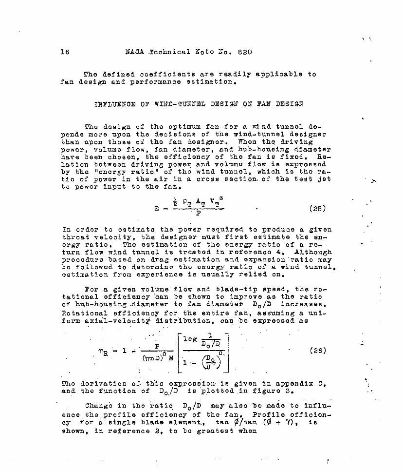
The defined coefficients are readily applicable tofan design and performance estimation.
INI’LU13NCIIOF WIND-TUNNEL! ilNSIGN 01? FAN DESIGN
The design of the optimum fan for a wind tunnel de-pends more upon the decisions of tile wind-tunnel designerthan upon those of the fan designer. When the drivingpower, volume flow, fan diameter, and hub-housing diameterhave been chosen, the efficiency of the fan is fixed. Re-lation between driving power and volumo flow is exprossodby the IIonergy ratio 11of tho wind tunnel, which is tho ra-tio of powor in the air in a cross section, of the test jetto power input to the fan.
>
In order to estimate the power required to produce a given..
throat velocity, the designer must first estimate the en-ergy ratio, The estimation of th-o energy ratio of a ro- .
turn flow wind tunnel is treated in roforenco 4. Althoughprocodure based on drag estimation and oxpansion”ratio maybo followod to detormi,no tho onorgy ratio of a wind tunnel, ,estimation from experience is usually relied on.
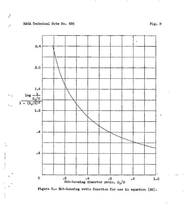
For a given volume flow and 31ade-tip speed, the ro-tational effieiency~can be shown to improve as the ratioof hub-housing diameter to fan diametefi Do /IJ increases,
Rotational efficiency for the entire fan, assuming a uni-form axial-velocit,j distribution, can ‘be expressed”as
,, ,.
p F-+ti ‘. .
,.. ,. .
1. 1.~0..%=’.l .’= ~o.. “ (26)
(u)1- -“
..
The der~vation of t.h’iseq?res{ion”is given in amendi~ ~,and the function of Do./D is plotted .in figure 3.
.
.,.
Change in the ra~io, Do/D may also be “made to influ-
ence the,.profile efficiency of the fan~ Profile officion-Cy for a single blade element,, tan @/tan (@ + 7), Is
shown, in reference 2, to ‘bo greatest when
1
i
..’
..
.
14
NACA Technical Nota No, 820 17
The value of ‘Y can be estimated with very small error.If volume flow, fan diameter, and rotational speed arefixed, an arrangement similar to that shown in figure 4will give high profile cfficie.ncy as WO1l as high rotation-al efficiency. Tho abrupt incroaso in tunnel-wall diame-ter pcrnits the uso 6f tho prodotormined Iarge-diamotcrfan at a location where the air velocity (assunod uniform)will at some noan radius givo a desirably’ largo helix an-gle. Tho hub Rousing is shaped to prosorve the contiriui~yof flow area for tho correct rate of ,diffusion.
Limitations to the gain. in efficiency obtainable byincreasing Do/D must be learned by experience. The di-vergence of the wind-tunnel mall ahead of tho fan shouldnot be so abrupt as to cause tho flow to separate from thetunnel wall. If countorvanos ar”o to be used in con~unc-tion with the fan, the rotational efficiency bocomos ofsecondary intcr~st because the rotational loss is rogainodexcept for tho small profile loss in the countorvanos thom-Solvos. Presumably tho advorso effect of increased ~ottedarea would, at some ~otnt~ offset the benefit of increased
efficiency. Influence’of the hub-housing diameter ratioDo/D is discussed in reference 1;
.-.
OPTIWM FAN DESIGN
‘tOptimum’fan N here implies a fan whose blado elementswork at the high”ost lift-drag ratio of tho air<oil socli6-n~A distribution .o’faxial velocity undistorted by the fan isalso implied. Design of a wind-tunnel fan is begun withthe information furnished by the wind-tunnel designer:volume flow, air density, drive poiwr, shaft speed, fan di-amctor, and hub-housing diameter. Tho number of bladesused is assumed not to influonco aerodynamic boh-avior ofth~ fan and is to be dotorminod chiefly from considerationsof ~lade strength, Blqde interference and number of bladesare dealt with in reference 1 and ‘blade strengt-h is dis-cussed in reference 5S Choice of nuwhcr of blades com-pletes the information noedod to computo the rotation con-stant of tho fan~ From equation (20.) .
P -,.T
= (nII)= B ~ ‘“

18 ITAGA Technical Note No,” 820
The first assumption to be made by the designer mustbe with regard to the di6tributiori) of axial velocitythrough the fan. An axial-velocity distribution%can be es-tablished by a judicious-use ,o& information con.tainod inrofercnces 6 and ‘7C This procedure” involv~,s .,cornpuiatiou
.
of the velocities in “tho boundary layer near a wall and inthe vicinity of, a body of given sQape and ai.jusirnent ofthe vel~c.ities t.o.give, the correct volume f-low, After muchwork, however, ‘the designer. will still have only an approx- ,‘imation. For mostwind-tunn.el-fan designs, the assumptionof un.ifo,rmaxial,velocity reduces labor and, except in ex-trenie cases+ does not introduae serious error. Detormlna-tion of helix angle, l)lado shape, and” bl”ado twist is moroor less straightforward and is.adapted to. ta%nila$iona
ECha helix anglo for each radial station can bo c’omputodfrom tho definition,
,, .
-1 . .
~ . tan - —--L—~rn-~. .,
.,
If equation (23) is substituted for W, fl tecomos afunction of J! and T.
1
●✎
(27)
After selection of the blade airfoil.profil~s, blade shaneand orientation can be determined fro~ equation (21), -
i
CLb=2D T sins $’r.. . .... J JsiIl (p+ 77 “. ‘
‘“.
Either lift coefficient or blade .width may be arbitrarilychosene For the optimum fan; the lift coefficient ischosen to correspond to the smallest.ialue of the
. .~/~
ratiO, shown by airfoil characteristics, and the bladewidth “is computed.. If the blad”e-w~dth ’distrib”ution is .
fixed, as is sometimes desirable:from strength co~sidera~.
tions, the lift coefficient can bo coqnzted by succossivoapproximations made with,.puq~~p,a.iva,lyassumed values of ‘Y-Usually two approximations, givq tho corroct lift cooffi-
.
.
.i-
9
. .lTACA Technical Hote Ho. 820 19
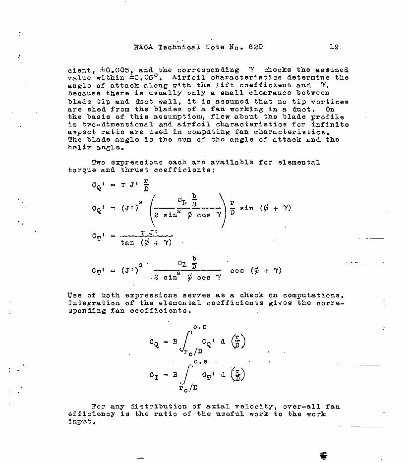
cie~t, &O O005, and the corresponding ?’ checks the assumedvalue within +0,05°. Airfoil characteristics determine theangle of attack along with the lift coefficient and ‘Y,Because there is usually only a small clearance %etmeenblade tip and duct wall, it is assumed that no tip vorticesare shed from the blades of a fan working in a duct. Onthe %asis of this assumption, flow about the blade profileis two-dimensional and airfoil characteristics for infiniteaspect ratio are used in computing fan characteristics.The blade angle is the sum of tho angle of attack and thehelix angle.
Two expressions each are available for elementaltorque and thrust coefficients:
Use of both expressions serves as a check on computations-Integration of the elemental coefficients gives the corre-sponding fan coefficients.
For any distribution of axial velocity, over-all fanefficiency is the ratio of the useful work to the workinput,
—

f
,,,VAT
.. .. . ,.. . ..:.,.,.. - ,+
T=
r
-,
2~n AQ’”\ .,
The torque” and.,tnrust, .increm.ents are given in equqtions(2) and (6) ,
m=
0.5
f
.
0Vpn2D43CTld~
r~/.D
D@ermination of the thrust and the efficiency of a fanfor a given power and the size ant the shape of the bladescomplotos tho aorodyqamic ‘dosigu..
,,
.
,.
(28)-
. .
NAOA l!e”chnical Note No. 820 21.
.-
,
.
.
it:-
. .FAN-PEZWORU.LN03! ‘ESTIMATION
Per form&rice estimation, as opposed to design, includesthe determination of power absorbed, thrust, mass flow, andefficiency of a fan, the size and the shape- of which arealready known. Fan performance, as well as design, dependsdirectly upon the energy ratio of the wind tunnel in whichtho fan works. Tho method of porformanc? ostirnation out-lined” here is based on the following assumptions: (1) Atany given time,”all elements of a fan operate at the samevalue of the ‘rotation constant; (2) the distribution ofaxial velocity, through the fan is controlled ?Jy the fanitself; and (3) a, different distribution exists for eachvalue of t-he rotation constant. This procedure is as a-p-pltcable to wrialle-pitch fans as to those having fixedblades, and in the case of either is laborious.
When information at hand consists only of the dimen-sions of the fan and the wind tunnel and the energy ratioof the wind tunnel, the analyst knows nothing of the fan~soperation except that a certain thrust will accoapany acertain mass flow. This fact is known from the wind-tunnelcharacteristics and leads to the following equation. (forderivation, see appendix D):
(29)
where the fan wind-tunnel constant
The design efficiency Tdesign in tho foregoing expression
is the fan efficiency that was assumed in coaputing theenergy ratio.
The relation involving the thrust-torque-rotation con-stant, expressed by equation (29), coupled with the perti-nent assumption that all blade elements operate at thesame value of tho rotation constant at a given instant fur-nishes means for a systematic analysis. Tho first stop is toprepare, for each r/D station, charts of CQ1 and CT ~
‘ 22 NACA Techni c&liNo”t.e.(No. 820
plotted against. J~ :(.flg.‘5)...’”TMeGe “:charts show values
of cQt , CTt S and ~t for constant blada angles and for
constant values of ,tho rotation, Constqpt T.,:. .,
Basic design infor,matiog,’~ill show whethqr tho %ladoangles are fixed or variab,le arid will indicate “the rangeof Jf and T over mhikh t.be blade olemehts’ will be ro-quirod to work. Ono s?t of co.mputdtions fixqs, CQl , CT~,
and the blade angle for. a sorios of aSsW~’d J: values atono valuo of T at onf3 r/D station. Fpr tho givoa r/Dstation,, a reasonable value of T is choson and sovoralJI values are. soloctod, which bracket. the worktng rangeof the sectione An outline of a sample computation pre-paring CQ1 and CT1 ,charts follows.
. .,..
,.,..”.
.
, ,...,,
—

.
.
. .
..
.
23
h-=b
T = Ka
Jt
tan
sin
M=
0.4
..
0.8
= T
=———.
1.6
24
,, ,.
NAOA Technical Note No. 823
---
-.—— .
----
/
,. —-
‘\.
7“”\----t---/J’”
/-?’
-----.
-- ‘.-
-- [7---;/‘---
---
--
-+
26 25°
= .08
● 06
.04
.02
.
..
%
.
,,.
,
. . .

KACA Technical Note Xo. .820 ‘M
.
..
.-
.“
When values 03? Cqf” &ria .ql are plotted, the corre-
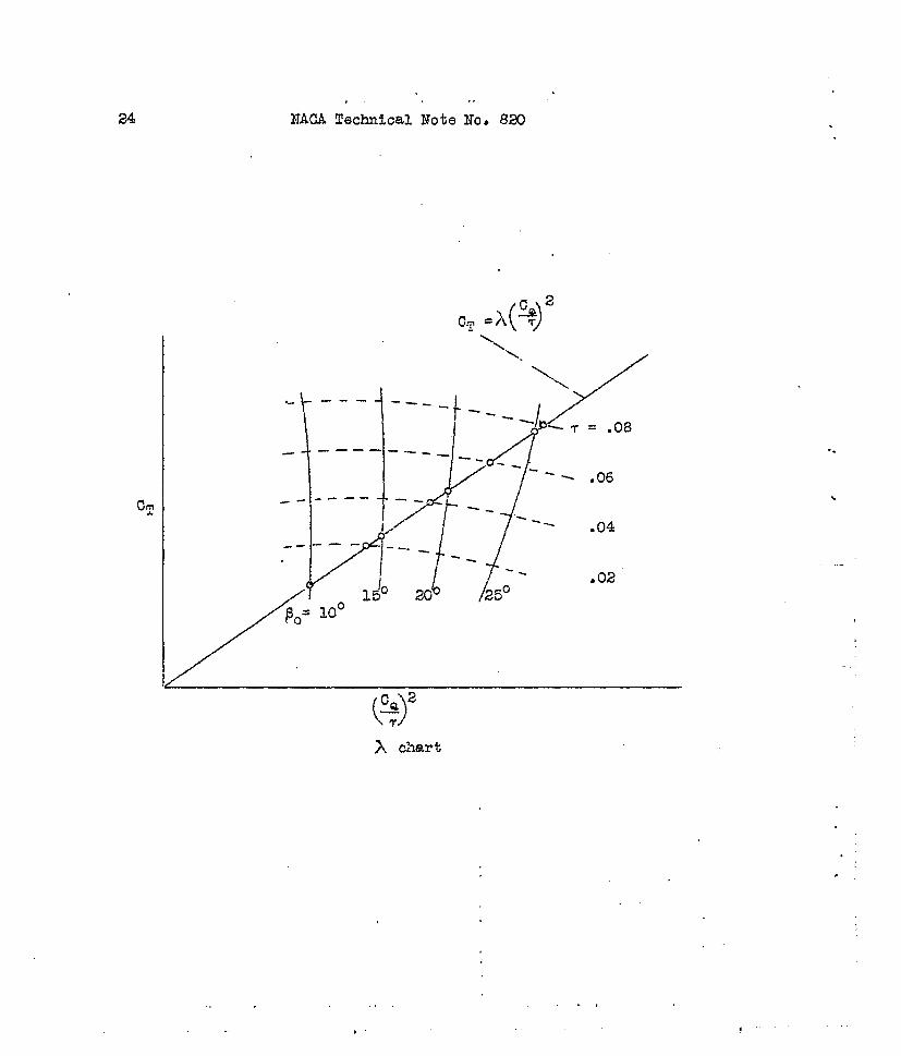
sponding values of. th8’b.1~.de a~n.glea“re”noted. The fore-”going cornpu%tion mist bp.rep.pate,d for. enbugh v’alues “of Tto cover the work”ing range of t,he fa-n. Curves for constantvalues of T Curves for constantcan be faired” dir”ectly.
.—
blade angles must be fa-ireilby imtbrpolating the valuesnoted in plotting. .Stmila5 chart’s must be.prepared f“or-fivo or six r/D stations. ,
.Consider performance estimation for a fixed-p&ch fan.
-.
The blade angle at each r/D station will be known. Forthe proper blade angle at each r~D station, read fromthe ~Q1 and ~T~ charts values of CQ1 and c~l corre-
sponding to a singlo value .of T. The value of JI willvary from station to station if the distributio~ of axialvelocity is not uniform. Integrate CQI and CT! to get
cQ. and CT* Repeat the foregoing procedure for two other. d
values of T and plot CT0
against + . On the same
chart plot equation (29). The iptorsoctton of the twocurves, shown in the following diagram called the A bhartj– ““—gives
CQ’ CTand, by interpolation, gives tho T V’aluo
under whit-h the fan operates at tho spot.ifiod blade-anglosottinga —-.
Tho chart shozm is for d “.variablo-pitch fan. For afixed-pitch, fan only ono $() curve cxistso .... .
Tabulate onc.ircled ‘points on A chart and computotho efficiency and tho mass f.lowi Tho form following is asimplo ono fo~ this purposo:. —,.
. .
IPo
T CT Cq ‘T~
(dog) . :. N
10.0 ~..
14.1
15.0
18.2
)

..
26 NACA Zochnical’ Noto No-. 820
-.
Further desirable information includes the efficiency,the axial-velocity distribution, and the mass flow, Axial-velocity distribution varies directly as J1. As the work-ing T is now known, as well as the blade angle, values ofCTI and Jt can be taken directly from tho CT I charts
and the integrated product J! (JTI can be used in equation
(28) to determine the fan efficiency. Mass flow can be ‘ ~computed from equation (30), which is derived from the def-inition of the rotation constant.
(30)
Throat velocity must be computed from the mass flowe Inas-much as fan diameter D is included in the primary infor-mation, all performance characteristics are now known interms of shaft speed. n. The shaft speed depends entirelyon the type of driving power rotating the fan. If the typeof driving power is ‘kn’own,tho thrust, tho po~or, ti~e of-ficioncy, and tho mass flow can bo found iumodiatoly forone blado-anglo setting.
If the wind-tunnel fan is of the variable-pitch type,analysts at each of a series of blade-angle settings willbe necessary. The A chart will then carry a curve foreach blade-angle setting as shown, Becauso the distribu.tion of ,axial velocity through tho fan is assumed to bononuniform and to vary with oporating conditions, tho slipfunction V/nil 10s0s some of its moaning. 3f3ttor paran-oters for expressing wind-tunnel fan characteristics areblado anglo f3 or rotation constant T. Final informa-tion, including shaft spood, powor, thrust, efficiency,and volumo flow, again is dopendont upon the type of driv-ing power.
Langley Memorial Aeronautical L.nboratory~National Advisory Comnittee for Aeronautics,
Langley Field, Vs., June 21, 1941.
..
“.
“,

\.& tio= +ApA&,@.Ldd(f~ - ‘. \4[rb - -
. hy.q.—o.A+——NACA Technical -Note
.
APPZNDIX A
When fluid moves through a fan with axial velocity Vat radius r , the force required to inpart continuously atangential velocity w to an annulus of fluid of thicknessAr is
AI’ = (mr Ar)PVw
If this force is Supplied,hy the fan rotating at shaftspeed n, pcz%verexpended in rotating the annulus of fluidis
AP = 2flrn AF= .%rn(%rr PVAr)w
.-
. .
.
,
Rotational energy in the annulus of fluid leaving thefan in unit time is
AE = (2Tr r P V A r)w~
which is equal to the power lost.
The rotational efficiency ofradius r is
power ioss~R]=l-——
power input
(2TTr P
the fan-blade element at
..-—
w’VAr)~
n#=l-Z
21T r n (%r PV Ar) w
‘J-lR’= 1 - -E.E--2mrn.’
.,
AFPEKDIX 3.
w’dr = qol (- wrdw + 43mwdr + %zrdw - w2dr) (14)
28 NACA Technical Note No. 820
Let
(1 -!-vo’) uadr = ?’10! (- wrti + %nwdr + %nrdw)
1 i-notwadr + wrdw - 2TTn (2wdr + rdw) = O
no 1
1
~wadr + 2w2dr - w2dr + ~d~ .- ~n ([email protected]+rd~) = o
1 -no’w2dr -+ w(2Wir + rd.u))- L~n (2Wdr+rdU}) = 0
To ‘
1 - qqol
To ‘w2dr + (2Wdr + rdu.))(w - 3TJ1) = O
1 - ?-[OI 2
()W ( w—. dr+2—To ‘ 2nn 2’i-rlldr’r%)(+-l)=o
and w
%Z=X
Then, ax~dr -I-(2xdr + rdx) (x - 1) = O
azz dr + 2xdr + riix = Ox-1
(x~
ax=+2X)
dr+rdx=O.
‘rr-+--k~— = o.—ax” + 2X( X.- 1)
dr~l— —
dx dx.—. = 0‘ax + 2(X -’1) axa + 2Xa - 2x
*+(a+2y~- 2-x[(a+d~)x-2J ‘0
Lot (a+2)=b
Then,
. .
. .
—
-,
r
.-
,

,.
NACk4 Technical Note No. 820 29
log r-f-~f
- ax
—+~Jti=”’”gc42X-.b
(2210gr+~-
log r2 x
1) log (: - x)+ log x = log c.
‘ x = c (; -‘$ ,-To
~-(:) (2T0 W
= c —. .l+~o 2Trn)
(15)
APPENDIX c
If a uniform distributidri” of axial velocity is as-sumed, the rotational efficiency of the entire fan i.s
j mass flow througlhannulus (at radius r) x elemental ~
%= M
.
. .
r .J +BD2 2mPVrTR = $,
21-rrPVdr -8TT2ra
-. -- .-
dr
.——

30 NACA ‘Technical Note No. 820 “
E’rom equation (20)
P= T B (IlD)2 M
~R=l-PVP
%.2. {PvnDa [0.25 - (~y]}
(26)
APPllNDIX D
The resistance of the interior of a wind tunnel toair flow through the tunnel is assumed here to increase asthe square of the throat velocity. The powor in a crosssection at the throat is
“$ PT & ATVT
The energy ratio is
~’ *“PTVT3AT ~=
P“
—
.
In order to indicate the effectiveness of the wind-tunneltube as a diffuser, tke” fan’”efficitincy ~design with
which the drive power is applied, must be stated. Thissame value of efficiency was assumed in computing the onor-fW ratio of tho wind tunnel.
*.
IIACA .Techn’ical :To.te’llo..:S20 31
.
“.
-.
.
.
E x shaft power ‘. 3 A~ = ~ M.,VT2* ~g VT .. .,,... . ...- .-
thrust power M TT=EX =
~design 2....,
(2
‘r%~T2 . — x mean velocity through fanPT AT )
[
PF AF 21TDa
‘Ta = — ‘-PT AT AE ~:;;, d G) ]2
o
— 2.
[
‘ 0.6Pr AF %mDzB
~T2= r ()]~ld: .
PT AT T 3Ay ~ Q
(r/D)~
.
(PF A.F 2nnD3
‘T2 7 n-
..- Tdesign ‘M. Thrust power =“ VT2
.2E
Thrust power = AT M
+~”x volume flow thrqugh fan = —PF AF ..,
. . . ..
M .~design ~’i.v~PF n2 D4 CT - =
.pF AF i 2E , T,. .
,.. . .

32
Let
NACA Technical Note ITo. 820
. .
REFERENCES
.,
1. Keller, Curt, Marks, Lionel S., and Weske, John R-:The Theory and Performance of Axial Flow Fans,McGraw-Hill Book Co.,. Inc., 1937.
2. Weibk, Fred E.: Aircraft Propeller Designe McGraw-Hill Book Co., Inc., 1930.
3. Glauert, H.: Fans . vol. IV, div. L, SOC, 6, ch, XIof Aerodynamic T’heory, ,lf.F. Durand, od., JuliusSpringer (Berlin), 1935,. pp. 338-341C
4. Wattendorf, FFank L. The Efficiency of Return FlowWind Tunnels. Reps. Nos, 4 & 5, Sci. Rep, Nat,Tsing Hua Univ, (Peiping), ser. A, vol. III, July1936, pp. 377-.402.
5. Oollar, A. R.: The Design of Wind Tunnel Fans. R-& MaNo. 1889, British A.R.C., 1940.
6. von K&rm&n, Th.:: Turbulence and Skin Friction, Jour,Aero, SCi., vol. 1, no. 1, Jan, 1934, PP. 1-200
,“
..
.
7. Zahm, A, F,: Flow and Drag Formulas for Simple Quad-rics. Rep. No. 253, lIACA, 13270
1

*.
NACA Technical Nofe No. 820 2
..
“s
“.
..
*
.
v
Y
.-— --
I
+’-+4
Figs. 1,
.—
.
.
NACA Technioal Note No. 820 Fig. 3*
‘,
“.
s.
,
2.4 “
2.0 [-
1.6 \
log ~Do/D ..
1- (Do/D)2 \
1.2 “
.8 —
.4 –—
0 .2 .4 .6 ●8 1.0Hub-housing dianeter ratio, Do/D
Figure 3.- ~b-housing ratio function for use in equation (26).
o
.

3,
* ,.
\ *
-,
*.
*.
NACA Technical NoTe Na 820 Figs.
72f127e/wall
,
4,5
.,. —
—
---- —-.
—