xbee wi-fi rf module user guide - digi international · sb(stopbits) 158 rocommand 158...
TRANSCRIPT

XBee® Wi-Fi RF ModuleS6B
User Guide

Revision history—90002180
Revision Date Description
L September2015
Fixed an error related to instructions for DIO13/DOUT. Added note to thePull Direction in the AT command table. Updated to new template.
M September2015
Added serial data interface and serial data throughput to the RFspecifications.
N April 2016 Updated Device Cloud and XCTU information. Explained the use of Zigbeeframes in the firmware. Added New Zealand certification information.
P May 2017 Added information on the Associate LED. Revised the manual. ChangedDevice Cloud to Remote Manager. Updated frame 0x20 Transmit options bitdescription.
R June 2017 Modified regulatory and certification information as required by RED (RadioEquipment Directive).
Trademarks and copyrightDigi, Digi International, and the Digi logo are trademarks or registered trademarks in the UnitedStates and other countries worldwide. All other trademarks mentioned in this document are theproperty of their respective owners.© 2017 Digi International Inc. All rights reserved.
DisclaimersInformation in this document is subject to change without notice and does not represent acommitment on the part of Digi International. Digi provides this document “as is,” without warranty ofany kind, expressed or implied, including, but not limited to, the implied warranties of fitness ormerchantability for a particular purpose. Digi may make improvements and/or changes in this manualor in the product(s) and/or the program(s) described in this manual at any time.
WarrantyTo view product warranty information, go to the following website:www.digi.com/howtobuy/terms
Send commentsDocumentation feedback: To provide feedback on this document, send your comments [email protected].
Customer supportDigi Technical Support: Digi offers multiple technical support plans and service packages to help ourcustomers get the most out of their Digi product. For information on Technical Support plans and
XBee Wi-Fi RF Module User Guide 2

pricing, contact us at +1 952.912.3444 or visit us at www.digi.com/support.
XBee Wi-Fi RF Module User Guide 3

Contents
Applicable firmware and hardware 12
Technical specificationsGeneral specifications 14RF characteristics 14RF data rates 14Receiver sensitivity 15RF transmit power - typical 16Error vector magnitude (EVM) maximum output power - typical 17Electrical specifications 18Serial communication specifications 19
UART pin assignments 20SPI pin assignments 20
GPIO specifications 20Regulatory conformity summary 21
HardwareMechanical drawings 23
Through-hole device 23Surface-mount device 24
Pin signals 24Design notes 26
Power supply 26Pin connection recommendations 27Board layout 27Antenna performance 27
Design notes for RF pad devices 29Mounting considerations 32
OperationSerial interface 34UART data flow 34Serial data 34SPI communications 35
Select the SPI port 36Serial buffers 36
Serial receive buffer 37
XBee Wi-Fi RF Module User Guide 4

XBee Wi-Fi RF Module User Guide 5
Serial transmit buffer 37UART flow control 37
CTS flow control 37RTS flow control 37
The Commissioning Button 38Connection indicators 39
The Associate LED 39TCP connection indicator 39Remote Manager connection indicator 40
Perform a serial firmware update 40
ModesSerial modes 42
Transparent operating mode 42API operating mode 42Commandmode 45
Modes of operation 47Idle mode 47Transmit mode 47Receive mode 47Configuration mode 47Sleepmode 49
Sleepmodes 49Soft AP mode 49
Enable Soft AP mode 49Station (STA) connection in Soft AP Provisioning mode 50Use the webpage to configure a connected device 50Station (STA) connection in Soft AP Pass Through mode 50
Sleep modesAbout sleepmodes 53Use the UART Sleepmode 53Use SPI Sleepmode 53AP Associated Sleepmode 54
Pin Sleepmode 54Cyclic Sleepmode 54
Deep Sleep (Non-Associated Sleep) mode 54Pin Sleepmode 55Cyclic Sleepmode 55
Use sleepmodes to sample data 55
802.11 bgn networksInfrastructure networks 57
Infrastructure Wireless Network 57Ad Hoc networks 57
Set Ad Hoc creator parameters 57Set Ad Hoc joiner parameters 58
Network basics 58802.11 standards 58Encryption 59
XBee Wi-Fi RF Module User Guide 6
Authentication 59Open authentication 59Shared Key 59Channels 59
IP servicesXBee Application Service 62
Local host access 62Network client access 63
Serial Communication Service 68Transparent mode 68UDP 68TCP 69API mode 69UDP mode 69TCP mode 69
I/O supportAnalog and digital I/O lines 71
Through-hole device 71Surface-mount device 71
Configure I/O functions 72I/O sampling 73Queried sampling 74Periodic I/O sampling 74Change detection sampling 75
Example 75RSSI PWM 75
Wi-Fi Protected Setup (WPS)Enable WPS 78Use WPS 78Pre-shared key (PSK) mode security 78
General Purpose Flash MemoryGeneral Purpose Flash Memory 80Work with flash memory 80Access General Purpose Flash Memory 80General Purpose Flash Memory commands 81
PLATFORM_INFO_REQUEST (0x00) 82PLATFORM_INFO (0x80) 82ERASE (0x01) 82ERASE_RESPONSE (0x81) 83WRITE (0x02) and ERASE_THEN_WRITE (0x03) 84WRITE _RESPONSE (0x82) and ERASE_THEN_WRITE_RESPONSE (0x83) 84READ (0x04) 85READ_RESPONSE (0x84) 85FIRMWARE_VERIFY (0x05) and FIRMWARE_VERIFY_AND_INSTALL(0x06) 86FIRMWARE_VERIFY_RESPONSE (0x85) 87
XBee Wi-Fi RF Module User Guide 7
FIRMWARE_VERIFY _AND_INSTALL_RESPONSE (0x86) 87Update the firmware over-the-air 88
Over-the-air firmware updates 89Distribute the new application 89Verify the new application 90Install the application 90
Configure the XBee Wi-Fi RF Module using Digi Remote ManagerUse XCTU to enable Remote Manager 92Configure the device 92Output control 93IO command bits 93Send I/O samples to Remote Manager 94View I/O samples in Remote Manager 94Update the firmware 95Send data requests 95Enable messages to the host 95About the device request and frame ID 96Populate and send a Device Request frame (0xB9) 96Transparent mode data 97
Send data to Remote Manager 97AT command settings to put serial data in Remote Manager 97Send files 98Send binary data points 98Receive data from Remote Manager 99
Operate in API modeAPI mode overview 101Use the AP command to set the operation mode 101API frame format 101
API operation (AP parameter = 1) 101API operation with escaped characters (AP parameter = 2) 102
API serial exchanges 105AT command frames 105Transmit and receive RF data 105Remote AT commands 106
Frame descriptions 107TX (Transmit) Request: 64-bit - 0x00 107Remote AT Command Request - 0x07 109AT Command Frame - 0x08 111Zigbee Transmit Packet - 0x10 112Zigbee Explicit Transmit Packet - 0x11 114Zigbee Remote AT Command - 0x17 117Transmit (TX) Request: IPv4 - 0x20 119Send Data Request - 0x28 121Device Response - 0x2A 123Rx (Receive) Packet: 64-bit - 0x80 124Remote Command Response - 0x87 126AT Command Response frame - 0x88 128Transmission Status frame - 0x89 129Modem Status frame - 0x8A 130Zigbee TX Status frame - 0x8B 131
XBee Wi-Fi RF Module User Guide 8
I/O Data Sample RX Indicator frame - 0x8F 133Zigbee Receive Packet frame 0x90 135Explicit Zigbee Receive Packet frame - 0x91 137Zigbee Remote AT Command Response frame - 0x97 139RX (Receive) Packet: IPv4 - 0xB0 141Send Data Response frame - 0xB8 143Device Request frame - 0xB9 144Device Response Status frame - 0xBA 145Frame Error - 0xFE 146
AT commandsAddressing commands 148
EQ (Device Cloud FQDN) 148Lookup IP Address of FQDN 148PG (Ping an IP Address) 148NS (DNS Address) 148DL command 149MY command 149MK command 149GW command 149SH command 150SL command 150NI (Node Identifier) 150DE command 150KP (Device Description) 150KC (Device Cloud Contact) 151KL (Device Location) 151C0 (Serial Communication Service Port) 151DD command 151NP (Maximum RF Payload Bytes) 152
Network commands 152DO command 152ID (SSID) 153AH (Network Type) 153IP (IP Protocol) 153MA (IP Addressing Mode) 153TM (Timeout) 154TS (TCP Server Socket Timeout) 154CE (Infrastructure Mode) 154
Security commands 154EE (Encryption Enable) 154PK command 155
RF interfacing commands 155PL (Power Level) 155CH (Channel) 156
Serial interfacing commands 156API Enable 156AO command 156BD (Baud Rate) 157NB (Serial Parity) 157SB (Stop Bits) 158RO command 158FT (Flow Control Threshold) 158D7 (DIO7 Configuration) 159
XBee Wi-Fi RF Module User Guide 9
D6 (DIO6 Configuration) 159I/O settings commands 160
IS command 160IR (I/O Sample Rate) 160IC (Digital Change Detection) 160IF (Sample from Sleep Rate) 161P0 (DIO10 Configuration) 161P1 (DIO11 Configuration) 161P2 (DIO12 Configuration) 162P3 (DOUT) 162P4 DIN 163P5 (DIO15 Configuration) 163P6 (DIO16 Configuration) 163P7 (DIO17 Configuration) 164P8 (DIO18 Configuration) 164P9 (DIO19 Configuration) 165D0 (DIO0/AD0/ CB Configuration) 165D1 (DIO1/AD1 Configuration) 165D2 (DIO2/AD2 Configuration) 166D3 (DIO3/AD3 Configuration) 166D4 (DIO4/AD4 Configuration) 167D5 (DIO5 Configuration) 167D8 (DIO8 Configuration) 168LT command 169PR (Pull-up Resistor) 169PD (Pull Direction) 170DS (Drive Strength) 170AV (Analog Voltage Reference) 171M0 (PWM0 Duty Cycle) 171M1 (PWM1 Duty Cycle) 171RP (RSSI PWM Timer) 171
Output Control 172IO command 172OM (Output Mask) 172T0 (Set time to hold DIO0) 172T1 (Set time to hold DIO1) 172T2 (Set time to hold DIO2) 173T3 (Set time to hold DIO3) 173T4 (Set time to hold DIO4) 173T5 (Set time to hold DIO5) 173T6 (Set time to hold DIO6) 173T7 (Set time to hold DIO7) 174T8 (Set time to hold DIO8) 174T9 (Set time to hold DIO9) 174Q0 (Set time to hold DIO10) 174Q1 (Set time to hold DIO11) 174Q2 (Set time to hold DIO12) 175Q3 (Set time to hold DIO13) 175Q4 (Set time to hold DIO14) 175Q5 (Set time to hold DIO15) 175Q6 (Set time to hold DIO16) 176Q7 (Set time to hold DIO17) 176Q8 (Set time to hold DIO18) 176Q9 (Set time to hold DIO19) 176
Diagnostics interfacing 177
XBee Wi-Fi RF Module User Guide 10
VR command 177HV command 177HS (Hardware Series) 177AI (Association Indication) 178DI (Device Cloud Indicator) 178AS command 179TP command 179CK (Configuration Code) 179%V (Supply Voltage) 180LM (Link Margin) 180
Commandmode options 180CT command 180CN command 180GT command 181CC (Command Mode Character) 181
Sleep commands 181SM (Sleep Mode) 181SP (Sleep Period) 182SO command 182WH (Wake Host) 182ST (Wake Time) 183SA command 183
Execution commands 183AC (Apply Changes) 183WR command 183RE command 184FR (Software Reset) 184NR (Network Reset) 184CB command 184
Regulatory informationUnited States (FCC) 187
OEM labeling requirements 187FCC notices 187FCC-approved antennas (2.4 GHz) 189RF exposure 194
Europe (CE) 195Maximum power and frequency specifications 195OEM labeling requirements 195Declarations of conformity 196Approved antennas 196
Canada (IC) 197Labeling requirements 197Transmitters with detachable antennas 197Detachable antenna 197
Australia (RCM)/New Zealand (R-NZ) 198Brazil (ANATEL) 198
Manufacturing informationRecommended solder reflow cycle 200Recommended footprint 200Mount the devices 202

XBee Wi-Fi RF Module User Guide 11
Flux and cleaning 203Rework 204
XBee Wi-Fi RF Module User Guide
The XBee Wi-Fi RF Module provides wireless connectivity to end-point devices in 802.11 bgn networks.Using the 802.11 feature set, these modules are interoperable with other 802.11 bgn devices,including devices from other vendors. With XBee Wi-Fi RF Module, you can have an 802.11 bgn networkup and running in a matter of minutes.The XBee Wi-Fi RF Modules are compatible with other devices that use 802.11 bgn technology. Theseinclude Digi external 802.11x devices like the ConnectPort products and the Digi Connect Wi-SP, aswell as embedded products like the ConnectCore series and Digi Connect series of products.
Applicable firmware and hardwareThis manual supports the following firmware:
n x202x
It supports the following hardware:n XB2B-WFxx-xxx
XBee Wi-Fi RF Module User Guide 12

Technical specifications
General specifications 14RF characteristics 14RF data rates 14Receiver sensitivity 15RF transmit power - typical 16Error vector magnitude (EVM) maximum output power - typical 17Electrical specifications 18Serial communication specifications 19GPIO specifications 20Regulatory conformity summary 21
XBee Wi-Fi RF Module User Guide 13
Technical specifications General specifications
XBee Wi-Fi RF Module User Guide 14
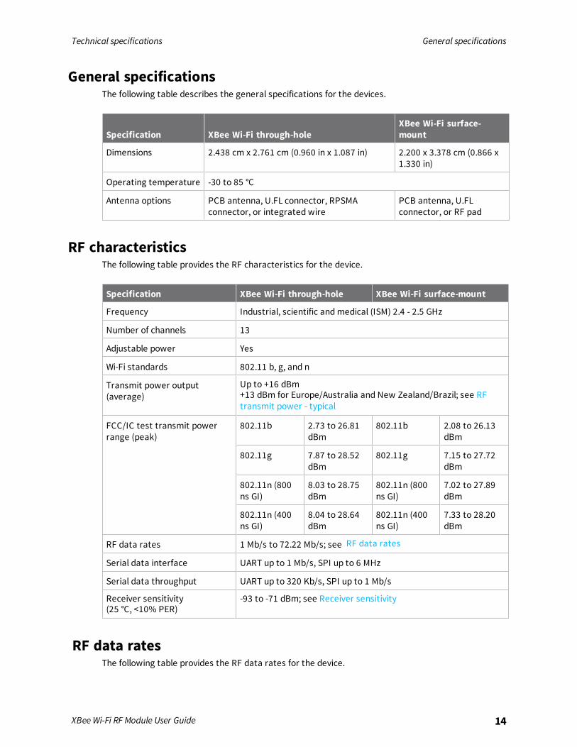
General specificationsThe following table describes the general specifications for the devices.
Specification XBee Wi-Fi through-holeXBee Wi-Fi surface-mount
Dimensions 2.438 cm x 2.761 cm (0.960 in x 1.087 in) 2.200 x 3.378 cm (0.866 x1.330 in)
Operating temperature -30 to 85 °C
Antenna options PCB antenna, U.FL connector, RPSMAconnector, or integrated wire
PCB antenna, U.FLconnector, or RF pad
RF characteristicsThe following table provides the RF characteristics for the device.
Specification XBee Wi-Fi through-hole XBee Wi-Fi surface-mount
Frequency Industrial, scientific andmedical (ISM) 2.4 - 2.5 GHz
Number of channels 13
Adjustable power Yes
Wi-Fi standards 802.11 b, g, and n
Transmit power output(average)
Up to +16 dBm+13 dBm for Europe/Australia and New Zealand/Brazil; see RFtransmit power - typical
FCC/IC test transmit powerrange (peak)
802.11b 2.73 to 26.81dBm
802.11b 2.08 to 26.13dBm
802.11g 7.87 to 28.52dBm
802.11g 7.15 to 27.72dBm
802.11n (800ns GI)
8.03 to 28.75dBm
802.11n (800ns GI)
7.02 to 27.89dBm
802.11n (400ns GI)
8.04 to 28.64dBm
802.11n (400ns GI)
7.33 to 28.20dBm
RF data rates 1 Mb/s to 72.22 Mb/s; see RF data rates
Serial data interface UART up to 1 Mb/s, SPI up to 6 MHz
Serial data throughput UART up to 320 Kb/s, SPI up to 1 Mb/s
Receiver sensitivity(25 °C, <10% PER)
-93 to -71 dBm; see Receiver sensitivity
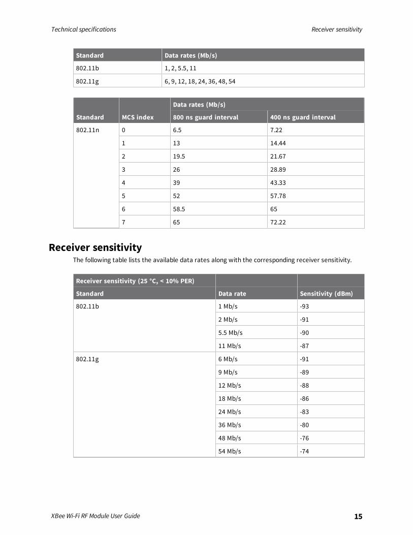
RF data ratesThe following table provides the RF data rates for the device.
Technical specifications Receiver sensitivity
XBee Wi-Fi RF Module User Guide 15
Standard Data rates (Mb/s)
802.11b 1, 2, 5.5, 11
802.11g 6, 9, 12, 18, 24, 36, 48, 54
Standard MCS index
Data rates (Mb/s)
800 ns guard interval 400 ns guard interval
802.11n 0 6.5 7.22
1 13 14.44
2 19.5 21.67
3 26 28.89
4 39 43.33
5 52 57.78
6 58.5 65
7 65 72.22
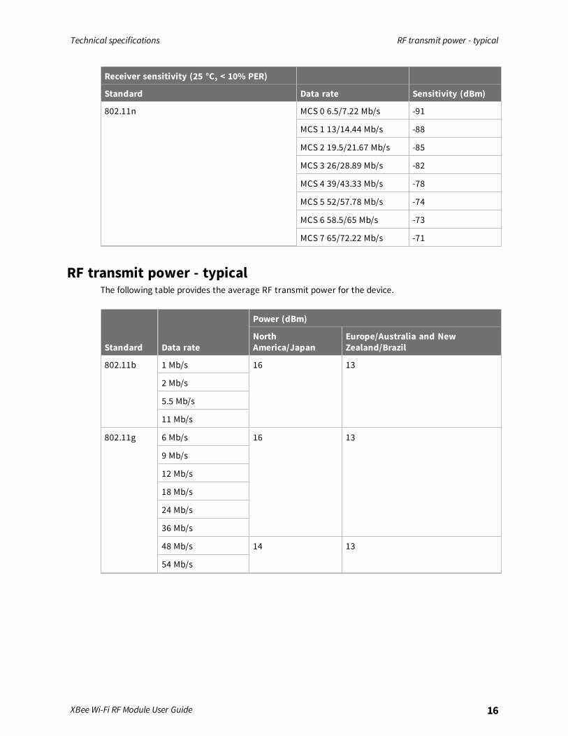
Receiver sensitivityThe following table lists the available data rates along with the corresponding receiver sensitivity.
Receiver sensitivity (25 °C, < 10% PER)
Standard Data rate Sensitivity (dBm)
802.11b 1 Mb/s -93
2 Mb/s -91
5.5 Mb/s -90
11 Mb/s -87
802.11g 6 Mb/s -91
9 Mb/s -89
12 Mb/s -88
18 Mb/s -86
24 Mb/s -83
36 Mb/s -80
48 Mb/s -76
54 Mb/s -74
Technical specifications RF transmit power - typical
XBee Wi-Fi RF Module User Guide 16
Receiver sensitivity (25 °C, < 10% PER)
Standard Data rate Sensitivity (dBm)
802.11n MCS 0 6.5/7.22 Mb/s -91
MCS 1 13/14.44 Mb/s -88
MCS 2 19.5/21.67 Mb/s -85
MCS 3 26/28.89 Mb/s -82
MCS 4 39/43.33 Mb/s -78
MCS 5 52/57.78 Mb/s -74
MCS 6 58.5/65 Mb/s -73
MCS 7 65/72.22 Mb/s -71
RF transmit power - typicalThe following table provides the average RF transmit power for the device.
Standard Data rate
Power (dBm)
NorthAmerica/Japan
Europe/Australia and NewZealand/Brazil
802.11b 1 Mb/s 16 13
2 Mb/s
5.5 Mb/s
11 Mb/s
802.11g 6 Mb/s 16 13
9 Mb/s
12 Mb/s
18 Mb/s
24 Mb/s
36 Mb/s
48 Mb/s 14 13
54 Mb/s

Technical specifications Error vector magnitude (EVM) maximum output power - typical
XBee Wi-Fi RF Module User Guide 17
Standard Data rate
Power (dBm)
NorthAmerica/Japan
Europe/Australia and NewZealand/Brazil
802.11n MCS 0 6.5/7.22 Mb/s 15 13
MCS 1 13/14.44 Mb/s
MCS 2 19.5/21.67Mb/s
MCS 3 26/28.89 Mb/s
MCS 4 39/43.33 Mb/s
MCS 5 52/57.78 Mb/s
MCS 6 58.5/65 Mb/s 14 13
MCS 7 65/72.22 Mb/s 8.5 8.5
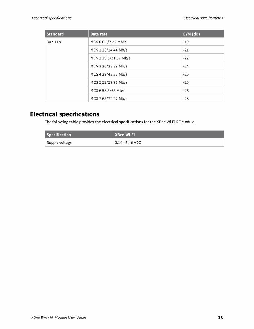
Error vector magnitude (EVM) maximum output power - typicalThe following table shows the EVM at 25 °C, maximum output power.
Standard Data rate EVM (dB)
802.11b 1 Mb/s -40
2 Mb/s -40
5.5 Mb/s -38
11 Mb/s -36
802.11g 6 Mb/s -18
9 Mb/s -20
12 Mb/s -21
18 Mb/s -22
24 Mb/s -22
36 Mb/s -23
48 Mb/s -25
54 Mb/s -26
Technical specifications Electrical specifications
XBee Wi-Fi RF Module User Guide 18
Standard Data rate EVM (dB)
802.11n MCS 0 6.5/7.22 Mb/s -19
MCS 1 13/14.44 Mb/s -21
MCS 2 19.5/21.67 Mb/s -22
MCS 3 26/28.89 Mb/s -24
MCS 4 39/43.33 Mb/s -25
MCS 5 52/57.78 Mb/s -25
MCS 6 58.5/65 Mb/s -26
MCS 7 65/72.22 Mb/s -28
Electrical specificationsThe following table provides the electrical specifications for the XBee Wi-Fi RF Module.
Specification XBee Wi-Fi
Supply voltage 3.14 - 3.46 VDC

Technical specifications Serial communication specifications
XBee Wi-Fi RF Module User Guide 19
Specification XBee Wi-Fi
Operating current (transmit,maximum output power)
802.11b 1 Mb/s 309 mA
2 Mb/s
5.5 Mb/s
11 Mb/s
802.11g 6 Mb/s 271 mA
9 Mb/s
12 Mb/s
18 Mb/s
24 Mb/s
36 Mb/s
48 Mb/s 225 mA
54 Mb/s
802.11n MCS 0 6.5/7.22 Mb/s 260 mA
MCS 1 13/14.44 Mb/s
MCS 2 19.5/21.67 Mb/s
MCS 3 26/28.89 Mb/s
MCS 4 39/43.33 Mb/s
MCS 5 52/57.78 Mb/s
MCS 6 58.5/65 Mb/s 217 mA
MCS 7 65/72.22 Mb/s 184 mA
Operating current (receive) 100 mA
Deep sleep current 6 µA @ 25 °C
Associated sleep current 2 mA asleep, 100 mA awake. For more information, see APAssociated Sleepmode.
Serial communication specificationsThe XBee Wi-Fi RF Module supports both Universal Asynchronous Receiver / Transmitter (UART) andSerial Peripheral Interface (SPI) serial connections.
Technical specifications GPIO specifications
XBee Wi-Fi RF Module User Guide 20
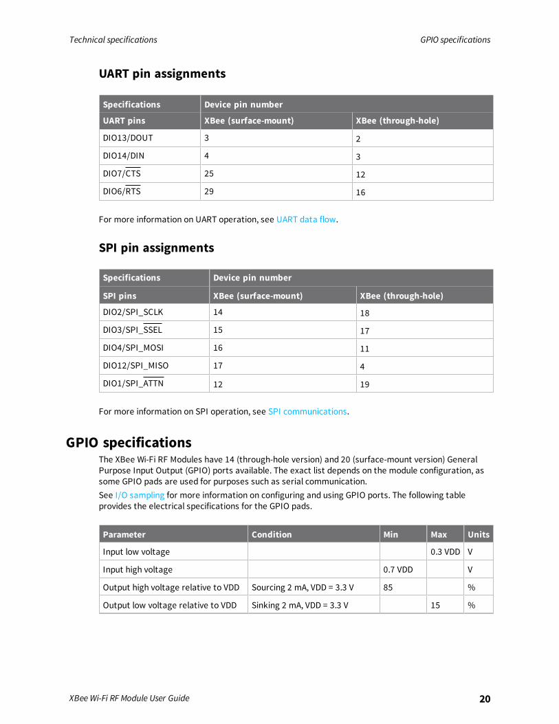
UART pin assignments
Specifications Device pin number
UART pins XBee (surface-mount) XBee (through-hole)
DIO13/DOUT 3 2
DIO14/DIN 4 3
DIO7/CTS 25 12
DIO6/RTS 29 16
For more information on UART operation, see UART data flow.
SPI pin assignments
Specifications Device pin number
SPI pins XBee (surface-mount) XBee (through-hole)
DIO2/SPI_SCLK 14 18
DIO3/SPI_SSEL 15 17
DIO4/SPI_MOSI 16 11
DIO12/SPI_MISO 17 4
DIO1/SPI_ATTN 12 19
For more information on SPI operation, see SPI communications.
GPIO specificationsThe XBee Wi-Fi RF Modules have 14 (through-hole version) and 20 (surface-mount version) GeneralPurpose Input Output (GPIO) ports available. The exact list depends on the module configuration, assome GPIO pads are used for purposes such as serial communication.See I/O sampling for more information on configuring and using GPIO ports. The following tableprovides the electrical specifications for the GPIO pads.
Parameter Condition Min Max Units
Input low voltage 0.3 VDD V
Input high voltage 0.7 VDD V
Output high voltage relative to VDD Sourcing 2 mA, VDD = 3.3 V 85 %
Output low voltage relative to VDD Sinking 2 mA, VDD = 3.3 V 15 %

Technical specifications Regulatory conformity summary
XBee Wi-Fi RF Module User Guide 21
Parameter Condition Min Max Units
Output fall time 2 mA drive strength and loadcapacitance CL= 350 - 600 pF.
20 +0.1 CL 250 ns
I/O pin hysteresis(VIOTHR+ - VIOTHR-)
VDD = 3.14 to 3.46 V 0.1 VDD V
Pulse width of pulses to be removedby the glitch suppression filter
10 50 ns
Regulatory conformity summaryThis table describes the agency approvals for the devices.
Country XBee Wi-Fi through-hole XBee Wi-Fi surface-mount
United States (FCC Part 15.247) FCC ID: MCQ-XBS6B FCC ID: MCQ-S6BSM
Industry Canada (IC) IC: 1846A-XBS6B IC: 1846A-S6BSM
Europe (CE) Yes Yes
Australia RCM RCM
New Zealand R-NZ R-NZ
Brazil ANATEL: 2672-13-1209 ANATEL: 2672-13-1209
Japan R210-101056 R210-101057
For details about FCC Approval (USA), see Regulatory information.

Hardware
Mechanical drawings 23Pin signals 24Design notes 26Design notes for RF pad devices 29Mounting considerations 32
XBee Wi-Fi RF Module User Guide 22

Hardware Mechanical drawings
XBee Wi-Fi RF Module User Guide 23
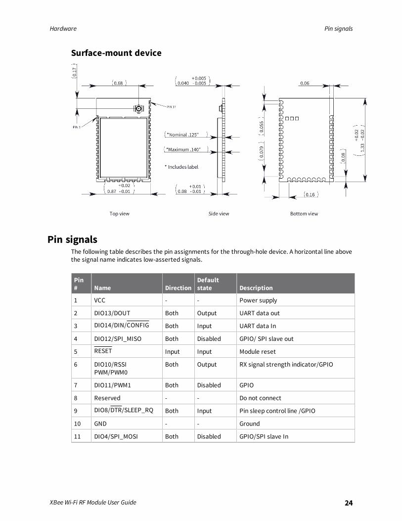
Mechanical drawingsThe following figures show the mechanical drawings for the XBee Wi-Fi RF Module. The drawings donot show antenna options. All dimensions are in inches.
Through-hole device
Hardware Pin signals
XBee Wi-Fi RF Module User Guide 24
Surface-mount device
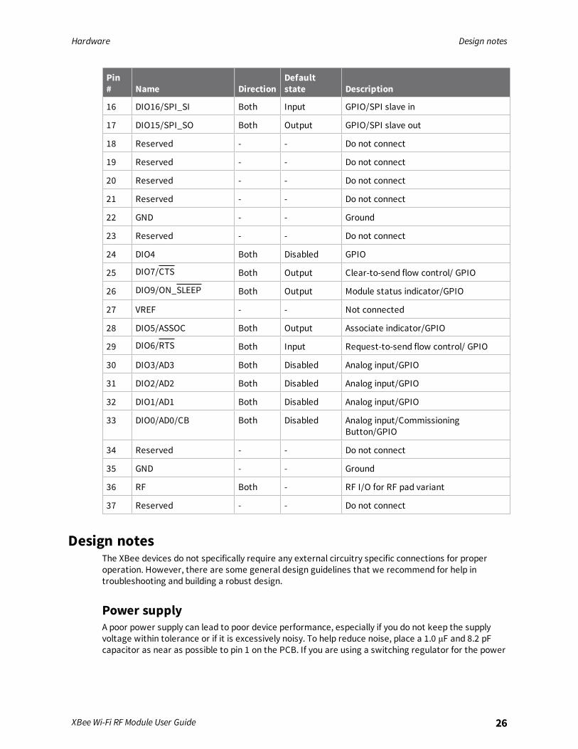
Pin signalsThe following table describes the pin assignments for the through-hole device. A horizontal line abovethe signal name indicates low-asserted signals.
Pin# Name Direction
Defaultstate Description
1 VCC - - Power supply
2 DIO13/DOUT Both Output UART data out
3 DIO14/DIN/CONFIG Both Input UART data In
4 DIO12/SPI_MISO Both Disabled GPIO/ SPI slave out
5 RESET Input Input Module reset
6 DIO10/RSSIPWM/PWM0
Both Output RX signal strength indicator/GPIO
7 DIO11/PWM1 Both Disabled GPIO
8 Reserved - - Do not connect
9 DIO8/DTR/SLEEP_RQ Both Input Pin sleep control line /GPIO
10 GND - - Ground
11 DIO4/SPI_MOSI Both Disabled GPIO/SPI slave In

Hardware Pin signals
XBee Wi-Fi RF Module User Guide 25
Pin# Name Direction
Defaultstate Description
12 DIO7/CTS Both Output Clear-to-send flow control/GPIO
13 DIO9/ON_SLEEP Both Output Module status indicator/GPIO
14 VREF - - Not connected
15 DIO5/ASSOCIATE Both Output Associate indicator/GPIO
16 DIO6/RTS Both Input Request-to-send flow control/GPIO
17 DIO3/AD3 /SPI_SSEL Both Disabled Analog input/GPIO/SPI slave select
18 DIO2/AD2 /SPI_CLK Both Disabled Analog input/GPIO/SPI clock
19 DIO1/AD1 /SPI_ATTN Both Disabled Analog input/GPIO/SPI attention
20 DIO0/AD0/CB Both Disabled Analog Input/CommissioningButton/GPIO
The following table describes the pin assignments for the surface-mount device. A horizontal lineabove the signal name indicates low-asserted signals.
Pin# Name Direction
Defaultstate Description
1 GND - - Ground
2 VCC - - Power supply
3 DIO13/DOUT Both Output UART data out
4 DIO14/DIN/CONFIG Both Input UART data in
5 DIO12 Both Disabled GPIO
6 RESET Input Input Module reset
7 DIO10/ RSSIPWM/PWM0
Both Output RX signal strength indicator/GPIO
8 DIO11/PWM1 Both Disabled GPIO
9 Reserved - - Do not connect
10 DIO8/DTR/SLEEP_RQ Both Input GPIO
11 GND - - Ground
12 DIO19/SPI_ATTN Both Output GPIO/SPI attention
13 GND - - Ground
14 DIO18/SPI_CLK Both Input GPIO/SPI clock
15 DIO17/SPI_SSEL Both Input GPIO/SPI slave select
Hardware Design notes
XBee Wi-Fi RF Module User Guide 26
Pin# Name Direction
Defaultstate Description
16 DIO16/SPI_SI Both Input GPIO/SPI slave in
17 DIO15/SPI_SO Both Output GPIO/SPI slave out
18 Reserved - - Do not connect
19 Reserved - - Do not connect
20 Reserved - - Do not connect
21 Reserved - - Do not connect
22 GND - - Ground
23 Reserved - - Do not connect
24 DIO4 Both Disabled GPIO
25 DIO7/CTS Both Output Clear-to-send flow control/ GPIO
26 DIO9/ON_SLEEP Both Output Module status indicator/GPIO
27 VREF - - Not connected
28 DIO5/ASSOC Both Output Associate indicator/GPIO
29 DIO6/RTS Both Input Request-to-send flow control/ GPIO
30 DIO3/AD3 Both Disabled Analog input/GPIO
31 DIO2/AD2 Both Disabled Analog input/GPIO
32 DIO1/AD1 Both Disabled Analog input/GPIO
33 DIO0/AD0/CB Both Disabled Analog input/CommissioningButton/GPIO
34 Reserved - - Do not connect
35 GND - - Ground
36 RF Both - RF I/O for RF pad variant
37 Reserved - - Do not connect
Design notesThe XBee devices do not specifically require any external circuitry specific connections for properoperation. However, there are some general design guidelines that we recommend for help introubleshooting and building a robust design.
Power supplyA poor power supply can lead to poor device performance, especially if you do not keep the supplyvoltage within tolerance or if it is excessively noisy. To help reduce noise, place a 1.0 μF and 8.2 pFcapacitor as near as possible to pin 1 on the PCB. If you are using a switching regulator for the power
Hardware Design notes
XBee Wi-Fi RF Module User Guide 27
supply, switch the frequencies above 500 kHz. Limit the power supply ripple to a maximum 50 mVpeak to peak.
Pin connection recommendationsThe only required pin connections are VCC, GND, and either DOUT and DIN or SPI_CLK, SPI_SSEL, SPI_MOSI, and SPI MISO. To support serial firmware updates, you should connect VCC, GND, DOUT, DIN,RTS, and DTR.Leave all unused pins disconnected. Use the PR command to pull all of the inputs on the device highusing 40 k internal pull-up resistors. You do not need a specific treatment for unused outputs.For applications that need to ensure the lowest sleep current, never leave inputs floating. Use internalor external pull-up or pull-down resistors, or set the unused I/O lines to outputs. You can achieve thedeep sleep (pin sleep) current specification using a standard XBee Interface Board with the XBee Wi-FiRF Module's pull-up and pull-down resistors configured as default.You can connect other pins to external circuitry for convenience of operation. For example, theAssociate signal (TH pin 15/SMT pin 28) and the ON_SLEEP signal (TH pin 13/SMT pin 26) will changelevel or behavior based on the state of the device.
Board layoutWhen designing the host PCB, account for the device dimensions shown in Mechanical drawings. SeeManufacturing information for the recommended footprints and required keepout areas. Use gooddesign practices when connecting power and ground, making those traces wide enough tocomfortably support the maximum currents or using planes if possible.
Antenna performanceAntenna location is important for optimal performance. The following suggestions help you achieveoptimal antenna performance. Point the antenna up vertically (upright). Antennas radiate and receivethe best signal perpendicular to the direction they point, so a vertical antenna's omnidirectionalradiation pattern is strongest across the horizon.Position the antennas away from metal objects whenever possible. Metal objects between thetransmitter and receiver can block the radiation path or reduce the transmission distance. Objectsthat are often overlooked include:
n metal poles
n metal studs
n structure beams
n concrete, which is usually reinforced with metal rods
If you place the device inside a metal enclosure, use an external antenna. Common objects that havemetal enclosures include:
n vehicles
n elevators
n ventilation ducts
n refrigerators
n microwave ovens
n batteries
n tall electrolytic capacitors

Hardware Design notes
XBee Wi-Fi RF Module User Guide 28
Do not place XBee devices with the chip or integrated PCB antenna inside a metal enclosure.Do not place any ground planes or metal objects above or below the antenna.For the best results, mount the device at the edge of the host PCB. Ensure that the ground, power,and signal planes are vacant immediately below the antenna section.
Keepout areaThe following drawings show important recommendations for designing with the PCB antennamodule using the through-hole and surface-mount devices. Do not mount the surface-mount PCBantenna module on the RF Pad footprint because that footprint requires a ground plane within thekeepout area.
Through-hole keepout
Notes1. We recommend non-metal enclosures. For metal enclosures, use an external antenna.
2. Keepmetal chassis or mounting structures in the keepout area at least 2.54 cm (1 in) from theantenna.
3. Maximize the distance between the antenna andmetal objects that might be mounted in thekeepout area.

Hardware Design notes for RF pad devices
XBee Wi-Fi RF Module User Guide 29
4. These keepout area guidelines do not apply for wire whip antennas or external RF connectors.Wire whip antennas radiate best over the center of a ground plane.
Surface-mount keepout
Notes1. We recommend non-metal enclosures. For metal enclosures, use an external antenna.
2. Keepmetal chassis or mounting structures in the keepout area at least 2.54 cm (1 in) from theantenna.
3. Maximize the distance between the antenna andmetal objects that might be mounted in thekeepout area.
4. These keepout area guidelines do not apply for wire whip antennas or external RF connectors.Wire whip antennas radiate best over the center of a ground plane.
Design notes for RF pad devicesThe RF pad is a soldered antenna connection. The RF signal travels from pin 33 the RF pad connection(pad 33 onmicro modules and pad 36 on surface-mount modules) on the device to the antenna

Hardware Design notes for RF pad devices
XBee Wi-Fi RF Module User Guide 30
through an RF trace transmission line on the PCB. Any additional components between the device andantenna violates modular certification. The controlled impedance for the RF trace is 50 Ω.We recommend using a microstrip trace, although you can also use a coplanar waveguide if you needmore isolation. A microstrip generally requires less area on the PCB than a coplanar waveguide. We donot recommend using a stripline because sending the signal to different PCB layers can introducematching and performance problems.Following good design practices is essential when implementing the RF trace on a PCB. Consider thefollowing points:
n Minimize the length of the trace by placing the RPSMA jack close to the device.
n Connect all of the grounds on the jack and the device to the ground planes directly or throughclosely placed vias.
n Space any ground fill on the top layer at least twice the distance d (in this case, at least 0.028")from the microstrip to minimize their interaction.
Additional considerations:n The top two layers of the PCB have a controlled thickness dielectric material in between.
n The second layer has a ground plane which runs underneath the entire RF pad area. Thisground plane is a distance d, the thickness of the dielectric, below the top layer.
n The top layer has an RF trace running from pin 33 of the device to the RF pin of the RPSMAconnector.
n The RF trace width determines the impedance of the transmission line with relation to theground plane. Many online tools can estimate this value, although you should consult the PCBmanufacturer for the exact width.
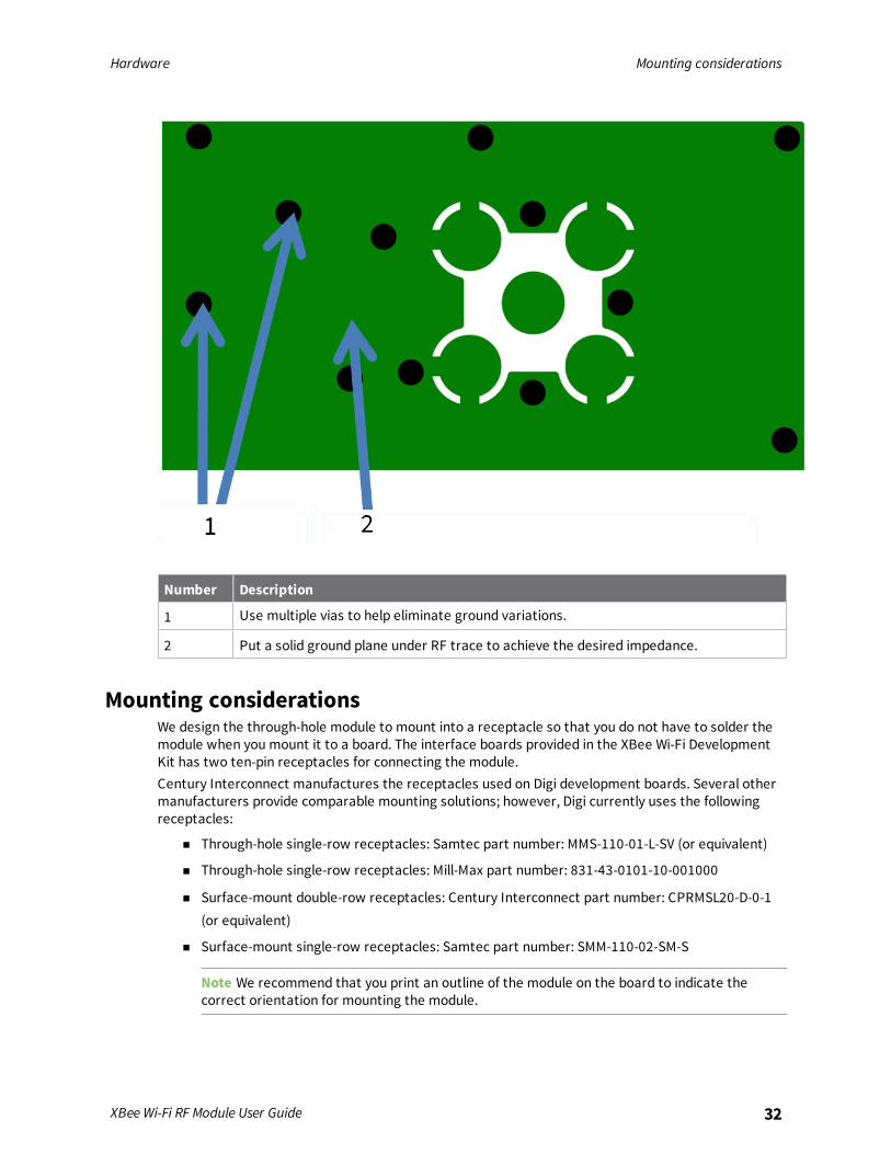
Implementing these design suggestions helps ensure that the RF pad device performs to itsspecifications.The following figures show a layout example of a host PCB that connects an RF pad device to a rightangle, through-hole RPSMA jack.

Hardware Design notes for RF pad devices
XBee Wi-Fi RF Module User Guide 31
Number Description
1 Maintain a distance of at least 2 d betweenmicrostrip and ground fill.
2 Device pin 33.
2 RF pad pin.
3 50 Ω microstrip trace.
4 RF connection of RPSMA jack.
The width in this example is approximately 0.025 in for a 50 Ω trace, assuming d = 0.014 in, and thatthe dielectric has a relative permittivity of 4.4. This trace width is a good fit with the device footprint's0.335" pad width.
Note We do not recommend using a trace wider than the pad width, and using a very narrow trace(under 0.010") can cause unwanted RF loss.
The following illustration shows PCB layer 2 of an example RF layout.
Hardware Mounting considerations
XBee Wi-Fi RF Module User Guide 32
Number Description
1 Use multiple vias to help eliminate ground variations.
2 Put a solid ground plane under RF trace to achieve the desired impedance.
Mounting considerationsWe design the through-hole module to mount into a receptacle so that you do not have to solder themodule when you mount it to a board. The interface boards provided in the XBee Wi-Fi DevelopmentKit has two ten-pin receptacles for connecting the module.Century Interconnect manufactures the receptacles used on Digi development boards. Several othermanufacturers provide comparable mounting solutions; however, Digi currently uses the followingreceptacles:
n Through-hole single-row receptacles: Samtec part number: MMS-110-01-L-SV (or equivalent)
n Through-hole single-row receptacles: Mill-Max part number: 831-43-0101-10-001000
n Surface-mount double-row receptacles: Century Interconnect part number: CPRMSL20-D-0-1(or equivalent)
n Surface-mount single-row receptacles: Samtec part number: SMM-110-02-SM-S
Note We recommend that you print an outline of the module on the board to indicate thecorrect orientation for mounting the module.

Operation
Serial interface 34UART data flow 34Serial data 34SPI communications 35Serial buffers 36UART flow control 37The Commissioning Button 38Connection indicators 39Perform a serial firmware update 40
XBee Wi-Fi RF Module User Guide 33

Operation Serial interface
XBee Wi-Fi RF Module User Guide 34
Serial interfaceThe XBee Wi-Fi RF Module interfaces to a host device through a serial port. The device cancommunicate through its serial port with:
n Through logic and voltage compatible universal asynchronous receiver/transmitter (UART).
n Through a level translator to any serial device, for example, through an RS-232 or USBinterface board.
n Through a serial peripheral interface (SPI) port.
UART data flowDevices that have a UART interface connect directly to the pins of the XBee Wi-Fi RF Module as shownin the following figure. The figure shows system data flow in a UART-interfaced environment. Low-asserted signals have a horizontal line over the signal name.
Serial dataA device sends data to the XBee Wi-Fi RF Module's UART through TH pin 3/SMT pin 4 DIN as anasynchronous serial signal. When the device is not transmitting data, the signals should idle high.For serial communication to occur, you must configure the UART of both devices (the microcontrollerand the XBee Wi-Fi RF Module) with compatible settings for the baud rate, parity, start bits, stop bits,and data bits.Each data byte consists of a start bit (low), 8 data bits (least significant bit first) and a stop bit (high).The following diagram illustrates the serial bit pattern of data passing through the device. Thediagram shows UART data packet 0x1F (decimal number 31) as transmitted through the device.
You can configure the UART baud rate, parity, and stop bits settings on the device with the BD, NB,and SB commands respectively. For more information, see Serial interfacing commands.
Operation SPI communications
XBee Wi-Fi RF Module User Guide 35
In the rare case that a device has been configured with the UART disabled, you can recover the deviceto UART operation by holding DIN low at reset time. DIN forces a default configuration on the UART at9600 baud and it brings the device up in Commandmode on the UART port. You can then send theappropriate commands to the device to configure it for UART operation. If those parameters arewritten, the device comes up with the UART enabled on the next reset.
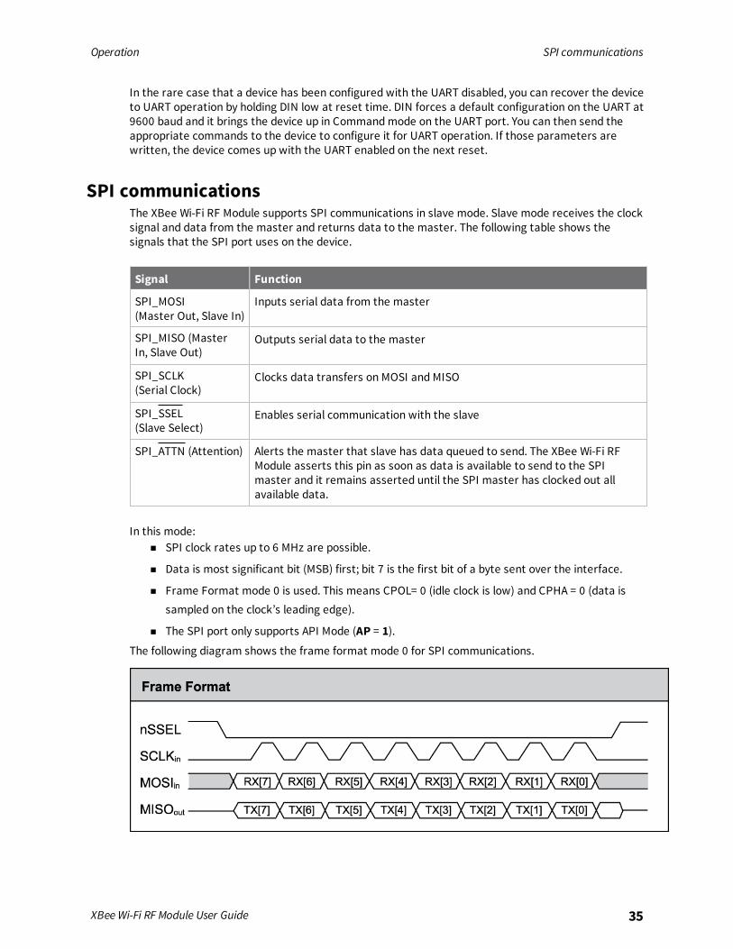
SPI communicationsThe XBee Wi-Fi RF Module supports SPI communications in slave mode. Slave mode receives the clocksignal and data from the master and returns data to the master. The following table shows thesignals that the SPI port uses on the device.
Signal Function
SPI_MOSI(Master Out, Slave In)
Inputs serial data from the master
SPI_MISO (MasterIn, Slave Out)
Outputs serial data to the master
SPI_SCLK (Serial Clock)
Clocks data transfers on MOSI and MISO
SPI_SSEL(Slave Select)
Enables serial communication with the slave
SPI_ATTN (Attention) Alerts the master that slave has data queued to send. The XBee Wi-Fi RFModule asserts this pin as soon as data is available to send to the SPImaster and it remains asserted until the SPI master has clocked out allavailable data.
In this mode:n SPI clock rates up to 6 MHz are possible.
n Data is most significant bit (MSB) first; bit 7 is the first bit of a byte sent over the interface.
n Frame Format mode 0 is used. This means CPOL= 0 (idle clock is low) and CPHA = 0 (data issampled on the clock’s leading edge).
n The SPI port only supports API Mode (AP = 1).The following diagram shows the frame format mode 0 for SPI communications.
Operation Serial buffers
XBee Wi-Fi RF Module User Guide 36
SPI mode is chip to chip communication. We do not supply a SPI communication option on the devicedevelopment evaluation boards.
Select the SPI portOn the through-hole devices, you can force SPI mode by holding DOUT/DIO13 low while resetting thedevice until SPI_ATTN asserts. This causes the device to disable the UART and go straight into SPIcommunication mode. Once configuration is complete, the device queues a modem status frame tothe SPI port, which causes the SPI_ATTN line to assert. The host can use this to determine that theSPI port is configured properly. This method forces the configuration to provide full SPI support for thefollowing parameters:
n D1 (This parameter will only be changed if it is at a default of zero when the method isinvoked.)
n D2
n D3
n D4
n P2As long as the host does not issue a WR command, these configuration values revert to previousvalues after a power-on reset. If the host issues a WR command while in SPI mode, these sameparameters are written to flash. After a reset, parameters that were forced and then written to flashbecome the mode of operation.If the UART is disabled and the SPI is enabled in the written configuration, then the device comes up inSPI mode without forcing it by holding DOUT low. If both the UART and the SPI are enabled at the timeof reset, then output goes to the UART until the host sends the first input. If that first input comes onthe SPI port, then all subsequent output goes to the SPI port and the UART is disabled. If the firstinput comes on the UART, then all subsequent output goes to the UART and the SPI is disabled.Once you select a serial port (UART or SPI), all subsequent output goes to that port, even if you apply anew configuration. The only way to switch the selected serial port is to reset the device. On surface-mount devices, forcing DOUT low at the time of reset has no effect. To use SPI mode on the SMTmodules, assert the SPI_SSEL (TH pin 17/SMT pin 15) low after reset and before any UART data isinput.When the master asserts the slave select (SPI_SSEL) signal, SPI transmit data is driven to the outputpin SPI_MISO, and SPI data is received from the input pin SPI_MOSI. The SPI_SSEL pin has to beasserted to enable the transmit serializer to drive data to the output signal SPI_MISO. A rising edgeon SPI_SSEL causes the SPI_MISO line to be tri-stated such that another slave device can drive it, if sodesired.If the output buffer is empty, the SPI serializer transmits the last valid bit repeatedly, which may beeither high or low. Otherwise, the device formats all output in API mode 1 format, as described inOperate in API mode. The attached host is expected to ignore all data that is not part of a formattedAPI frame.
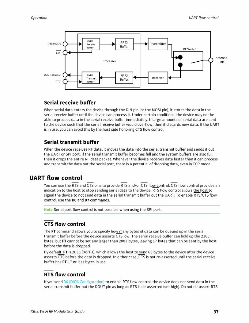
Serial buffersThe XBee Wi-Fi RF Module maintains internal buffers to collect serial and RF data that it receives. Theserial receive buffer collects incoming serial characters and holds them until the device can processthem. The serial transmit buffer collects the data it receives via the RF link until it transmits that dataout the UART or SPI port. The following figure shows the process of device buffers collecting receivedserial data.
Operation UART flow control
XBee Wi-Fi RF Module User Guide 37
Serial receive bufferWhen serial data enters the device through the DIN pin (or the MOSI pin), it stores the data in theserial receive buffer until the device can process it. Under certain conditions, the device may not beable to process data in the serial receive buffer immediately. If large amounts of serial data are sentto the device such that the serial receive buffer would overflow, then it discards new data. If the UARTis in use, you can avoid this by the host side honoring CTS flow control.
Serial transmit bufferWhen the device receives RF data, it moves the data into the serial transmit buffer and sends it outthe UART or SPI port. If the serial transmit buffer becomes full and the system buffers are also full,then it drops the entire RF data packet. Whenever the device receives data faster than it can processand transmit the data out the serial port, there is a potential of dropping data, even in TCP mode.
UART flow controlYou can use the RTS and CTS pins to provide RTS and/or CTS flow control. CTS flow control provides anindication to the host to stop sending serial data to the device. RTS flow control allows the host tosignal the device to not send data in the serial transmit buffer out the UART. To enable RTS/CTS flowcontrol, use the D6 and D7 commands.
Note Serial port flow control is not possible when using the SPI port.
CTS flow controlThe FT command allows you to specify how many bytes of data can be queued up in the serialtransmit buffer before the device asserts CTS low. The serial receive buffer can hold up the 2100bytes, but FT cannot be set any larger than 2083 bytes, leaving 17 bytes that can be sent by the hostbefore the data is dropped.By default, FT is 2035 (0x7F3), which allows the host to send 65 bytes to the device after the deviceasserts CTS before the data is dropped. In either case, CTS is not re-asserted until the serial receivebuffer has FT-17 or less bytes in use.
RTS flow controlIf you send D6 (DIO6 Configuration) to enable RTS flow control, the device does not send data in theserial transmit buffer out the DOUT pin as long as RTS is de-asserted (set high). Do not de-assert RTS
Operation The Commissioning Button
XBee Wi-Fi RF Module User Guide 38
for long periods of time or the serial transmit buffer will fill. If the device receives an RF data packetand the serial transmit buffer does not have enough space for all of the data bytes, it discards theentire RF data packet.If the device sends data out the UART when RTS is de-asserted (set high) the device could send up tofour characters out the UART port after RTS is de-asserted. This means your application needs to de-assert RTS by the time its receive capacity is within 4 bytes of full.
The Commissioning ButtonThe XBee Wi-Fi RF Module supports a set of commissioning and LED functions to help you deploy andcommission devices. These functions include the Commissioning Button definitions and the associatedLED functions.To enable the Commissioning Button functionality on TH pin 20/SMT pin 33, set DO command to 1. Thefunctionality is enabled by default.Use the CB command to simulate button presses in software. Send CB with a parameter set to thenumber of button presses to perform. For example, if you send CB2, the device performs the action(s)associated with two button presses, CB4 is four button presses. See CB command.It provides two different services:
n Two button presses in fast sequence invoke WPS; see Wi-Fi Protected Setup (WPS).
n Four button presses in fast sequence force the device into Soft AP Provisioning mode byclearing the SSID and security parameters. It also ensures that Soft AP mode is enabled. Afterthe four button presses clear the security parameters, they are NOT written. Send a separateWR command, if desired.
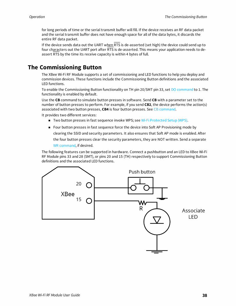
The following features can be supported in hardware. Connect a pushbutton and an LED to XBee Wi-FiRF Module pins 33 and 28 (SMT), or pins 20 and 15 (TH) respectively to support Commissioning Buttondefinitions and the associated LED functions.

Operation Connection indicators
XBee Wi-Fi RF Module User Guide 39
Connection indicatorsThere are four connection indicators in this software:
n AI (Association Indication)
n The Associate LED
n TCP connection indicator
n Remote Manager connection indicator
The Associate LEDThe Associate pin (TH pin 15/SMT pin 28) provides an indication of when the device associates with anaccess point (AP). To take advantage of these indications, connect an LED to the Associate pin.To enable the Associate LED functionality, set D5 (DIO5 Configuration) to 1; it is enabled by default. Ifenabled, the Associate pin is configured as an output.Use LT command to override the blink rate of the Associate pin. If you set LT to 0, the device uses thedefault blink time: 250 ms.
TCP connection indicatorIn Transparent mode, only one TCP connection is allowed and you can configure DIO12 (also known asCD) to indicate whether or not that TCP socket is connected. To enable DIO12, set P2 (DIO12Configuration) to 6. When so configured, DIO12 outputs a low signal when the TCP socket is connectedand it outputs a high signal when the TCP socket is disconnected. The high signal remains whenoperating in UDP mode because there is never be a TCP connection.

Operation Perform a serial firmware update
XBee Wi-Fi RF Module User Guide 40
Remote Manager connection indicatorAI (Association Indication) and the Associate LED indicate when the device is fully associated with theaccess point (AP), but there is another level of connectivity provided by DI (Device Cloud Indicator) thattells whether or not the TCP socket to Digi Remote Manager is connected. The values defined for DIare:
n 0 = Connected to Remote Manager
n 1 = Configured, but not yet associated to AP
n 2 = Associated to AP, but not yet connected to Remote Manager
n 3 = Disconnecting from Remote Manager
n 4 = Not configured to connect to Remote Manager
When DI is either 2 or 3, the Associate LED has a different blink pattern that looks like this:
Where the low signal means LED off and the high signal means LED on.The normal association LED signal alternates evenly between high and low as shown below:
Perform a serial firmware updateSerial firmware updates use the XBee bootloader which ships in all devices. This bootloader allows youto update the firmware. Normally, the running application can be told to invoke the bootloaderthrough a command from XCTU. If that command is not available in the currently loaded firmware, thebootloader includes a modified entry mechanism using pins TH pin 3/SMT pin 4, TH pin 9/SMT pin 10,and TH pin 16/SMT pin 29 (DIN, DTR, and RTS, respectively).To force the XBee bootloader to run and load a new version of the firmware, at the time the device isreset:
1. Drive DIN low.
2. Drive DTR low.
3. Drive RTS high.
This method works even when the current firmware version does not support the firmware upgradefeature. XCTU can update firmware on the XBee Wi-Fi RF Module over the UART port, but not over theSPI port. Contact Digi support for details.
Modes
Serial modes 42Modes of operation 47Sleepmodes 49Soft AP mode 49
XBee Wi-Fi RF Module User Guide 41
Modes Serial modes
XBee Wi-Fi RF Module User Guide 42
Serial modesThe firmware operates in several different modes. Two top-level modes establish how the devicecommunicates with other devices through its serial interface: Transparent operating mode and APIoperating mode. Use the AP command to choose Serial mode. XBee Wi-Fi RF Modules use Transparentoperation as the default serial mode.The following modes describe how the serial port sends and receives data.
Transparent operating modeDevices operate in this mode by default. The device acts as a serial line replacement when it is inTransparent operating mode. The device queues all UART data it receives through the DIN pin for RFtransmission. When a device receives RF data, it sends the data out through the DOUT pin. You can setthe configuration parameters using Commandmode.
Note Transparent operating mode is not available when using the SPI interface; see SPIcommunications.
Serial-to-RF packetizationThe device buffers data in the serial receive buffer until one of the following causes the data to bepacketized and transmitted:
n The device receives no serial characters for the amount of time determined by the RO(Packetization Timeout) parameter. If RO = 0, packetization begins when a character isreceived. If RO is non-zero, the data is packetized after RO character times of no transitions onthe DIN pin. However, if the time required for RO characters is less than 100 microseconds,then DIN must still be idle for at least 100 microseconds, which is the minimal idle timerequired for packetizing packets at any baud rate.
n The device receives the Command Mode Sequence (GT + CC + GT). Any character buffered inthe serial receive buffer before the sequence is transmitted.
n The device receives the maximum number of characters that fits in an RF packet (100 bytes).
API operating modeApplication programming interface (API) operating mode is an alternative to Transparent mode. It ishelpful in managing larger networks and is more appropriate for performing tasks such as collectingdata from multiple locations or controlling multiple devices remotely. API mode is a frame-basedprotocol that allows you to direct data on a packet basis. It can be particularly useful in largenetworks where you need control over the operation of the radio network or when you need to knowwhich node a data packet is from. The device communicates UART or SPI data in packets, also knownas API frames. This mode allows for structured communications with serial devices.The application programming interface (API) provides alternative means of configuring devices androuting data at the host application layer. A host application can send data frames to the device thatcontain address and payload information instead of using Commandmode to modify addresses. Thedevice sends data frames to the application containing status packets, as well as source and payloadinformation from received data packets.For more information, see API mode overview.

Modes Serial modes
XBee Wi-Fi RF Module User Guide 43
Comparing Transparent and API modesThe XBee Wi-Fi RF Module can use its serial connection in two ways: Transparent mode or APIoperating mode. You can use a mixture of devices running API mode and transparent mode in anetwork.The following table compares the advantages of transparent and API modes of operation:
Feature Description
Transparent mode features
Simple interface All received serial data is transmitted unless the device is in Commandmode
Easy to support It is easier for an application to support Transparent operation andCommandmode
API mode features
Easy to manage datatransmissions tomultiple destinations
Transmitting RF data to multiple remote devices only requires theapplication to change the address in the API frame. This process is muchfaster than in Transparent mode where the application must enterCommandmode, change the address, exit Commandmode, and thentransmit data.
Each API transmissioncan return a transmitstatus frame indicatingthe success or reasonfor failure
Because acknowledgments are sent out of the serial interface, thisprovides more information about the health of the RF network and canbe used to debug issues after the network has been deployed.
Received data framesindicate the sender'saddress
All received RF data API frames indicate the source address
Advanced addressingsupport
API transmit and receive frames can expose addressing fields includingsource and destination endpoints, cluster ID, and profile ID
Advanced networkingdiagnostics
API frames can provide indication of I/O samples from remote devices,and node identification messages. Some network diagnostic tools such asTrace Route, NACK, and Link Testing can only be performed in API mode.
Remote Configuration Set/read configuration commands can be sent to remote devices toconfigure them as needed using the API
We recommend API mode when a device:n Sends RF data to multiple destinations
n Sends remote configuration commands to manage devices in the network
n Receives RF data packets from multiple devices, and the application needs to know whichdevice sent which packet
n Must support multiple endpoints, cluster IDs, and/or profile IDs
n Uses the Device Profile services
API mode is required when:

Modes Serial modes
XBee Wi-Fi RF Module User Guide 44
n Receiving I/O samples from remote devices
n Using SPI for the serial port
n Sends RF data to multiple destinations
n Sends remote configuration commands to manage devices in the network
n Receives IO samples from remote devices
n Receives RF data packets from multiple devices, and the application needs to know whichdevice sent which packet
n Needs to use the send data request and device request features of Remote Manager
If the conditions listed above do not apply (for example, a sensor node, router, or a simple application),then Transparent operation might be suitable. It is acceptable to use a mixture of devices running APImode and Transparent mode in a network.The following table provides a comparison of the two modes.
Transparent operating mode API operating mode
When to use:n The conditions for using API mode
do not apply.
When to use:n The device sends wireless data to multiple
destinations.
n The device configures remote devices in thenetwork.
n The device receives wireless data packets frommultiple XBee devices, and the application needsto identify which devices send each packet.
n The device receives I/O samples from remoteXBee devices.
Advantages:n Provides a simple interface.
n It is easy for an application tosupport; what you send is exactlywhat other modules get, and viceversa.
n Works very well for two-waycommunication between XBeedevices.
Advantages:n You can set or read the configuration of remote
XBee devices in the network.
n You can transmit data to one or multipledestinations; this is much faster thanTransparent mode where the configuration mustbe updated to establish a new destination.
n Received data includes the sender's address.
n Received data includes transmission details andreasons for success or failure.
n This mode has several advanced features, suchas advanced networking diagnostics, andfirmware upgrades.

Modes Serial modes
XBee Wi-Fi RF Module User Guide 45
Transparent operating mode API operating mode
Disadvantages:n You cannot set or read the
configuration of remote XBeedevices in the network.
n You must first update theconfiguration to establish a newdestination and transmit data.
n You cannot identify the source ofreceived data, as it does notinclude the sender's address.
n Received data does not includetransmission details or thereasons for success or failure.
n This mode does not offer theadvanced features of API mode,including advanced networkingdiagnostics, and firmwareupgrades.
Disadvantages:n The interface is more complex; data is
structured in packets with a specific format.
n This mode is more difficult to support;transmissions are structured in packets thatneed to be parsed (to get data) or created (totransmit data).
n Sent data and received data are not identical;received packets include some control data andXTend vB information.
Command modeCommandmode is a state in which the firmware interprets incoming characters as commands. Itallows you to modify or read the device’s firmware using parameters you can set using AT commands.See Operate in API mode for an alternate means of configuring devices, which is the only methodavailable for SPI mode.Commandmode is available on the UART interface in both Transparent and API modes. You cannotuse the SPI interface to enter Commandmode.
Enter Command modeTo get a device to switch into this mode, you must issue the following sequence: GT + CC(+++) + GT.When the device sees a full second of silence in the data stream (the guard time) followed by thestring +++ (without Enter or Return) and another full second of silence, it knows to stop sending datathrough and start accepting commands locally.
Note Do not press Return or Enter after typing +++ because it will interrupt the guard time silenceand prevent you from entering Commandmode.
When you send the Commandmode sequence, the device sends OK out the UART pin. The device maydelay sending the OK if it has not transmitted all of the serial data it received.When the device is in Commandmode, it listens for user input and is able to receive AT commands onthe UART. If CT time (default is 10 seconds) passes without any user input, the device drops out ofCommandmode and returns to Receive mode.
Modes Serial modes
XBee Wi-Fi RF Module User Guide 46
You can customize the guard times and timeout in the device’s configuration settings. For informationon how to do this, see CC (Command Mode Character), CT command and GT command.
TroubleshootingFailure to enter Commandmode is often due to baud rate mismatch. Ensure that the baud rate of theconnection matches the baud rate of the device. By default, the BD parameter = 3 (9600 b/s).
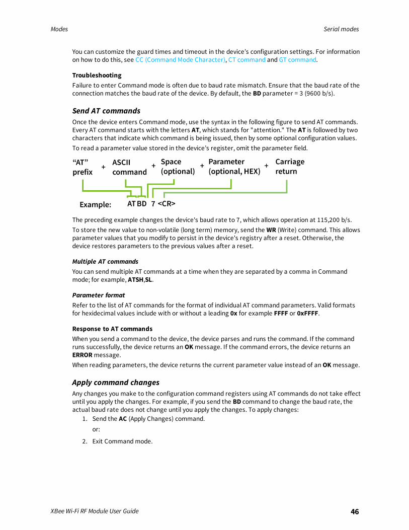
Send AT commandsOnce the device enters Commandmode, use the syntax in the following figure to send AT commands.Every AT command starts with the letters AT, which stands for "attention." The AT is followed by twocharacters that indicate which command is being issued, then by some optional configuration values.To read a parameter value stored in the device’s register, omit the parameter field.
The preceding example changes the device's baud rate to 7, which allows operation at 115,200 b/s.To store the new value to non-volatile (long term) memory, send the WR (Write) command. This allowsparameter values that you modify to persist in the device's registry after a reset. Otherwise, thedevice restores parameters to the previous values after a reset.
Multiple AT commandsYou can sendmultiple AT commands at a time when they are separated by a comma in Commandmode; for example, ATSH,SL.
Parameter formatRefer to the list of AT commands for the format of individual AT command parameters. Valid formatsfor hexidecimal values include with or without a leading 0x for example FFFF or 0xFFFF.
Response to AT commandsWhen you send a command to the device, the device parses and runs the command. If the commandruns successfully, the device returns anOKmessage. If the command errors, the device returns anERRORmessage.When reading parameters, the device returns the current parameter value instead of anOKmessage.
Apply command changesAny changes you make to the configuration command registers using AT commands do not take effectuntil you apply the changes. For example, if you send the BD command to change the baud rate, theactual baud rate does not change until you apply the changes. To apply changes:
1. Send the AC (Apply Changes) command.or:
2. Exit Commandmode.

Modes Modes of operation
XBee Wi-Fi RF Module User Guide 47
Exit Command mode1. Send the CN (Exit Command Mode) command followed by a carriage return.
or:
2. If the device does not receive any valid AT commands within the time specified by CT(Command Mode Timeout), it returns to Idle Mode.
For an example of programming the device using AT Commands and descriptions of each configurableparameter, see AT commands.
Modes of operation
Idle modeWhen not receiving or transmitting data, the device is in Idle mode. During Idle mode, the devicelistens for valid data on both the RF and serial ports.The device shifts into the other modes of operation under the following conditions:
n Transmit mode (serial data in the serial receive buffer is ready to be packetized).
n Receive mode (valid RF data received through the antenna).
n Sleepmode (Sleepmode condition is met).
n Commandmode (Commandmode sequence issued).
Transmit modeWhen the device receives serial data and is ready to packetize it, the device attempts to transmit theserial data. The destination address determines which node(s) will receive and send the data.
Receive modeThis is the default mode for the XBee Wi-Fi RF Module. The device is in Receive mode when it is nottransmitting data. If a destination node receives a valid RF packet, the destination node transfers thedata to its serial transmit buffer.
Configuration modeYou may not always know the parameters that the XBee Wi-Fi RF Module is configured with. If thoseparameters affect how the XBee Wi-Fi RF Module enters Commandmode, and if the parameters werepreviously written to non-volatile memory, then Commandmode is not available to either read theparameters or to set them to known values. This makes configuring the device difficult unless you cansuccessfully guess the configuration to allow it to enter Commandmode.An example of this problem is when the UART baud rate is unknown. In this case, the +++ sequence toenter Commandmode is not recognized due to a baud rate mismatch, preventing the device fromentering Commandmode.
Force the device to enter Configuration modeTo overcome the issue of unknown configuration parameters, you can force the XBee Wi-Fi RF Moduleinto Commandmode with a known configuration as follows:While holding DIN low (asserting the break key), reset the device.

Modes Modes of operation
XBee Wi-Fi RF Module User Guide 48
Rather than coming up in Transparent mode, which is normal, it comes up in Commandmode andissues the OK prompt with the following default parameters applied for operation while in Commandmode:
Parameter setting Meaning
P3 = 1, P4 = 1 UART enabled—only set for SPI-enabled devices
BD = 3 9600 baud rate
SB = 0 One stop bit
NB = 0 No parity
RO = 3 Three character times with no change on DIN before transmission
D6 = 0 No RTS flow control
D7 = 1 CTS flow control
FT 65 characters left in transmission buffer before CTS is turned off
CC = 0x2b + is used for Commandmode character
GT = 0x3e8 One second guard time
CT = 0x64 Ten second Commandmode timeout
If the XBee Wi-Fi RF Module exits Configuration mode without changing any parameter values, then allparameters revert to their previous unknown state after it exits Commandmode. Also, any valuesthat you query return the previously written settings rather than the temporarily applied defaultsettings described above.
Recover from an unknown configurationTo recover from an unknown configuration to a known configuration, do the following:
1. Set up the interface to the XBee Wi-Fi RF Module to match the default configuration describedin Force the device to enter Configuration mode.
2. Press and hold DIN low while resetting the XBee Wi-Fi RF Module.
3. Release DIN (let it be pulled high) so the device can receive UART data.
4. At the OK prompt, enter the desired configuration settings. If desired, configuration settingswhich were unknownmay be read before setting them in this state.
5. Use the WR command to write the desired configuration to non-volatile memory.
6. Set up the interface to the XBee Wi-Fi RF Module to match the configuration just written tonon-volatile memory.
7. Optionally, reset the device and begin operation in the new mode.
Use XCTU to enter Configuration modeXCTU is designed to support a forced configuration on a UART interface using the followinginstructions. XCTU does not work directly over a SPI interface.

Modes Sleep modes
XBee Wi-Fi RF Module User Guide 49
1. Connect an asynchronous serial port of the PC (either RS-232 or USB) to the developmentboard that the XBee Wi-Fi RF Module is plugged into.
2. Open XCTU.
3. To add your device to XCTU, see Add radio modules to XCTU in the XCTU User Guide.
4. The device(s) appear under the Radio Modules section on the left of the display.
5. To configure the settings, see Configure your modules in the XCTU User Guide.
6. When you are done entering the parameters, click the Write module settings button.When the write is complete, all of the settings on the device are updated.Click the Consoles working mode button on the toolbar and begin normal Transparent operation.
Sleep modeSleepmodes allow the device to enter states of low power consumption when not in use. The XBeeWi-Fi RF Module supports both pin sleep (Sleepmode entered on pin transition) and cyclic sleep(device sleeps for a fixed time).
Sleep modesSleepmodes allow the device to enter states of low power consumption when not in use. The XBeeWi-Fi RF Module supports both pin sleep (sleepmode entered on pin transition) and cyclic sleep (devicesleeps for a fixed time). For both pin sleep and cyclic sleep the sleep level may be either deep sleep orassociated sleep. See Sleepmodes for more information.
Soft AP modeThe XBee Wi-Fi RF Module can operate in Soft AP mode, also known as Wi-Fi Direct. In this mode theXBee Wi-Fi RF Module emulates an access point (AP) rather than a station (STA). This allows anotherWi-Fi client device (STA) to connect to the XBee device directly without requiring a separate AP. WPA2security is available in Soft AP mode, but not WPA or WEP security. By default, Soft AP operates withno security.
Enable Soft AP modeThe device operates in Soft AP mode in two different ways:
1. Provisioning mode
2. Pass through mode
You enable these two modes differently. To enable Pass through mode:Set CE (Infrastructure Mode) to 1, which is not the default configuration. When CE is 1, it overridesparameters for Provisioning mode.Provisioning mode is enabled by default. To disable it:Clear bit 1 of DO command.To enable Provisioning mode, SSID must be NULL. SSID is NULL by default and you can force it to NULLby issuing NR (Network Reset).

Modes Soft AP mode
XBee Wi-Fi RF Module User Guide 50
Station (STA) connection in Soft AP Provisioning modeWhen the device operates in Soft AP Provisioning mode, it waits for a connection from a STA device.Because the Service Set Identifier (SSID) is not configured, AI (Association Indication) is 0x23. The STAdevice must:
n Support Wi-Fi
n Have an HTTP browser operating on TCP port 80
Examples of devices that might connect to the XBee Wi-Fi RF Module operating in Soft AP mode aresmart phones, tablets, and laptop computers.The connecting STA device should scan for an AP. The XBee Wi-Fi RF Module advertises an SSID of:
xbee<MAC>where <MAC> is the 6 byte MAC address of the XBee Wi-Fi RF Module formatted as follows:
xbee-XXXXXXXXXXXXwhere each X represents a hex digit.The STA needs to connect to that SSID, and then open a browser by entering 192.168.1.10 into theaddress bar. This opens the webpage from the XBee Wi-Fi RF Module to allow you to configure it asdesired. The primary purpose of this webpage is to configure the XBee Wi-Fi RF Module to connect tothe desired access point with the desired security settings. The secondary purpose is to configure anyother parameters.
Use the webpage to configure a connected deviceThe webpage displays the current value of each configuration field.
1. Enter the desired parameters.
2. Click the Apply button at the bottom of the page.
The selected parameters are written to the non-volatile memory on the XBee Wi-Fi RF Module.However, the network access parameters are only written if you enter a valid set of parameters. Thedevice tests the validity of those parameters by attempting to connect to the given access point.
n The Soft AP webpage provides the same configuration options that are available in XCTU.
n The webpage is divided into sections that expand or collapse by clicking Show or Hide. The onlysection expanded by default is the Network Access section.
n All fields proceeded with 0x must be hex values.
Note Do not programmatically configure the device in Soft AP mode because it is subject to change.
Station (STA) connection in Soft AP Pass Through modeWhen the XBee Wi-Fi RF Module operates in Soft AP Pass Through mode, it does not use HTTP on port80 and it operates the same as it would in STA mode with a few exceptions:
n Only one device may connect and the connecting device must be operating in STA mode.
n A TCP listening socket on the port specified by C0 (Serial Communication Service Port) is opento accept connections, but no UDP listening socket is available.
n ID (SSID) specifies the SSID sent by the XBee Wi-Fi RF Module in the beacon, but if ID is NULL, itadvertises an SSID based on the device’s MAC address. For details, see Enable Soft AP mode.

Modes Soft AP mode
XBee Wi-Fi RF Module User Guide 51
n AI (Association Indication) is 0x23 while in Soft AP Provisioning mode (because ID is NULL), butAI is 0 in Soft AP Pass Through mode as soon as the XBee Wi-Fi RF Module is ready to accept aconnection from a STA device. This is true whether or not ID is null.

Sleep modes
About sleepmodes 53Use the UART Sleepmode 53Use SPI Sleepmode 53AP Associated Sleepmode 54Deep Sleep (Non-Associated Sleep) mode 54Use sleepmodes to sample data 55
XBee Wi-Fi RF Module User Guide 52
Sleep modes About sleep modes
XBee Wi-Fi RF Module User Guide 53
About sleep modesThe XBee Wi-Fi RF Module supports two different sleepmodes:
n Pin Sleep
n Cyclic Sleep
In addition, you can modify the sleepmode current draw with the following sleep options:n AP Associated Sleep
n Deep Sleep
Pin sleep allows an external microcontroller to determine when the XBee Wi-Fi RF Module shouldsleep and when it should wake by using either the SLEEP_RQ pin (default) or the SPI_SSEL pin. Incontrast, cyclic sleep allows the sleep period and wake times to be configured using AT commands.The device can stay associated to the access point or can enter a deeper sleep and associate to theaccess point for each sleep/wake occurrence. The sleepmode is configurable with the SM and SOcommands.Each of the sleepmodes operate differently based on the serial interface (UART or SPI).
Use the UART Sleep modeWhen the serial interface is UART, the ON_SLEEP pin is used to indicate that the device is enteringsleepmode, unless it is configured for a different usage. If you configure Sets or displays the DIO9configuration (TH pin 13/SMT pin 26). for ON_SLEEP, then it is driven low when asleep and high whenawake, whether using pin sleep or cyclic sleep.If you enable CTS hardware flow control with D7 (DIO7 Configuration), the CTS pin is de-asserted(high) when entering sleep to indicate that serial data should not be sent to the device. The device willnot respond to serial or RF data when it is sleeping. Applications that use the UART are encouraged toobserve CTS flow control in any of the sleepmodes. When the XBee Wi-Fi RF Module wakes from sleepwith flow control enabled, the CTS pin is asserted (low).If using pin sleep, you must configure D8 (DIO8 Configuration) for SLEEP_RQ to put the device to sleep.Otherwise, there is no sleep at all, meaning the device always stays awake in full power mode. Whenyou configure D8 for SLEEP_RQ, the host should drive SLEEP_RQ high to put the device to sleep, andthe host should drive SLEEP_RQ low to wake up the device.
Use SPI Sleep modeWhen the serial interface is SPI, SPI_ATTN is used as an attention indicator to tell the SPI masterwhen it has data to send. Since SPI only operates in API mode, it asserts SPI_ATTN and sends out amodem status indicator after initialization. The host can use this to know when the device is ready tooperate as a SPI slave. Since the function of SPI_ATTN is to indicate when the device has data to sendto the host, it may legitimately be driven high or low while the device is awake.When using SPI, you can use either SLEEP_RQ or SPI_SSEL for pin sleep. If D8 (DIO8 Configuration) isconfigured as a peripheral (1), then it is used for pin sleep. If not, and SPI_SSEL is configured as aperipheral (which it must be to enable SPI operation), then SPI_SSEL is used for pin sleep.Using SPI_SSEL for pin sleep has the advantage of requiring one less physical pin connection toimplement pin sleep on SPI. It has the disadvantage of putting the device to sleep whenever the SPImaster negates SPI_SSEL, even if that was not the intent. Therefore, if you can control SPI_SSEL,whether or not data needs to be transmitted, then sharing the pin may be a good option. It makes theSLEEP_RQ pin available for another purpose, or it simply requires one less pin to the SPI interface.

Sleep modes AP Associated Sleep mode
XBee Wi-Fi RF Module User Guide 54
AP Associated Sleep modeThis option allows the device to sync up with beacons sent from the Access Point (AP) which containsthe Delivery Traffic Indication Message (DTIM). The DTIM indicates when broadcast andmulticast datais sent on the network. This property is configured on the AP and is typically configured as the numberof beacons between each beacon with DTIM.The current draw in Associated Sleepmode varies significantly. When the device is awake it drawsapproximately 100 mA. When it is asleep, it draws approximately 2 mA. Total current draw increaseswhen the DTIM rate is higher and it decreases when the DTIM rate is lower on the access point.The sleepmodes described in this user guide have this option enabled.
Pin Sleep modeUART data can be received in pin sleepmode, whether or not the host asserts the SLEEP_RQ pin. Forexample, if RF data is received by the device while SLEEP_RQ is asserted, the device wakes up longenough to send the data out the UART and then immediately resumes sleeping. If wake host isconfigured, the device asserts the appropriate I/O lines (indicating that it is awake), then waits forwake host timer to expire, then outputs the data, and then immediately resumes sleeping.In this mode, when SLEEP_RQ is asserted the device powers down the Wi-Fi circuitry. When SLEEP_RQis de-asserted, the Wi-Fi circuitry is powered up. This causes the device to associate to the accesspoint for each wake event. If the device was associated when it went to sleep, it should be ready totransmit data as soon as the ON_SLEEP pin indicates that the device is awake. If the device was notassociated when it went to sleep, the host must wait until the device is associated before atransmission can occur. In API mode, a modem status frame is received when the device becomesassociated. Outside of API mode, the AI commandmust be used to determine when the device isassociated.SPI operation is similar except that the device asserts ATTN when data becomes available and thenthe local host is expected to assert SPI_SSEL and to provide a clock until the data available is sent out.When the local UART host needs to send data it de-asserts SLEEP_RQ. Once the appropriate statusI/O lines are asserted (CTS and/or ON_SLEEP) the device is ready to accept data. However data willbe queued and not sent until the next DTIM.When the local SPI host needs to send data it asserts SPI_SSEL. If SPI_SSEL is being used for pin sleep,asserting SPI_SSEL is enough to awaken the device to receive the incoming data. But, if SLEEP_RQ isbeing used to control sleep, then SPI_SSELmust be asserted and SLEEP_RQ must be de-asserted toawaken the device to receive the data. This wakes up the device, which then accepts the incomingdata; however, data is queued and not sent until the next DTIM.
Cyclic Sleep modeThe device remains associated to the Access Point (AP) and sleeps based on the SP (Sleep Period)parameter. After SP expires, the device wakes for 30 milliseconds to check for data from the AP andto allow the host to send data or commands. This time is factored in as part of the overall ST time.When data is received or sent within 30 ms, the device remains awake for ST time and any furtheractivity does not restart this time. When no data is received or sent within 30 ms, the device resumessleep immediately, without waiting for ST time-out.
Deep Sleep (Non-Associated Sleep) modeThis option allows the Wi-Fi circuitry to be powered down resulting in the lowest sleep current (about6 µA) but at the expense of losing packets received during the time the device is asleep. This is

Sleep modes Use sleep modes to sample data
XBee Wi-Fi RF Module User Guide 55
because the Access Point behaves like the device is in full power mode while it is asleep and it will nothold back packets until the device wakes up.
Pin Sleep modeIn this mode when SLEEP_RQ is asserted the device powers down the Wi-Fi circuitry. When SLEEP_RQis de-asserted the Wi-Fi circuitry is powered up. This causes the device to associate to the accesspoint for each wake event. If the device was associated when it went to sleep, it should be ready totransmit data as soon as the ON_SLEEP pin indicates that the device is awake. If the device was notassociated when it went to sleep, the host must wait until the device is associated before atransmission can occur. In API mode, a modem status frame is received when the device becomesassociated. Outside of API mode, AI (Association Indication) must be used to determine when thedevice is associated.
Cyclic Sleep modeIn this mode the device enters and exits sleep based on the SP (Sleep Period), ST (Wake Time), and SAcommand commands. SP specifies the sleep time and ST specifies the wake time of the device after itis associated. SA specifies the maximum time to wait for association before starting the ST timer. IfSA expires before the association process completes, then the device sleeps anyway. When it wakesfrom this state, then it starts the SA timer again to seek to establish association.Under normal conditions, SA is used for a time out for the first association following reset and ST isused for short wake cycles thereafter. To conserve battery power, SA should be long enough forassociation and ST should be as short as possible for the application.
Use sleep modes to sample dataTo sample data when waking from any sleepmode:
1. Enable an ADC or digital input.
2. Set IR (I/O Sample Rate) appropriately with respect to ST (Wake Time) to obtain the desirednumber of samples.
If you want multiple samples during the wake period then user IR. This provides ST/IR+1 samples.Each sample is sent separately.WH (Wake Host) delays UART and sample data from being initiated until the timer has expired. Thisallows the host to wake up before receiving data or a sensor to power up before an I/O sample istaken.Digital outputs and special function outputs such as ON_SLEEP and CTS are not affected byWH. This isto allow these signals to be used to wake up devices.For deep sleep,WHmust be expired and the device must be associated before I/O samples are taken.
802.11 bgn networks
Infrastructure networks 57Ad Hoc networks 57Network basics 58802.11 standards 58Encryption 59Authentication 59Open authentication 59Shared Key 59Channels 59
XBee Wi-Fi RF Module User Guide 56

802.11 bgn networks Infrastructure networks
XBee Wi-Fi RF Module User Guide 57
Infrastructure networksThe main type of wireless network involve a number of wireless devices called stations talkingthrough a master wireless device known as an access point (AP) or station (STA). This type of setup iscalled an Infrastructure or Basic Service Set (BSS) network. Most wireless networks are of this type.The following illustration is an example of an infrastructure wireless network.
Infrastructure Wireless NetworkBy default, the XBee Wi-Fi RF Module operates as a STA in the infrastructure network, which means itassociates to an AP and all data to and from the device goes through that AP.If you configure CE (Infrastructure Mode) to 1, the device takes the position of an AP in the network,allowing STA devices to associate to the XBee Wi-Fi RF Module operating in Soft AP mode.
Ad Hoc networksWireless devices can join a wireless network without an access point. This is called an Ad Hoc orIndependent Basic Service Set (IBSS) network.
Note Ad Hoc networks are point to point: there can only be two nodes in the network, a creator and ajoiner. Set up the creator first, and then the joiner.
Set Ad Hoc creator parametersSet the following parameters for the creator:
Parameter Function
AH1 Designates the node as an Ad Hoc creator.
MA1 Specifies the static IP addresses. No DHCP is supported in Ad Hoc mode.
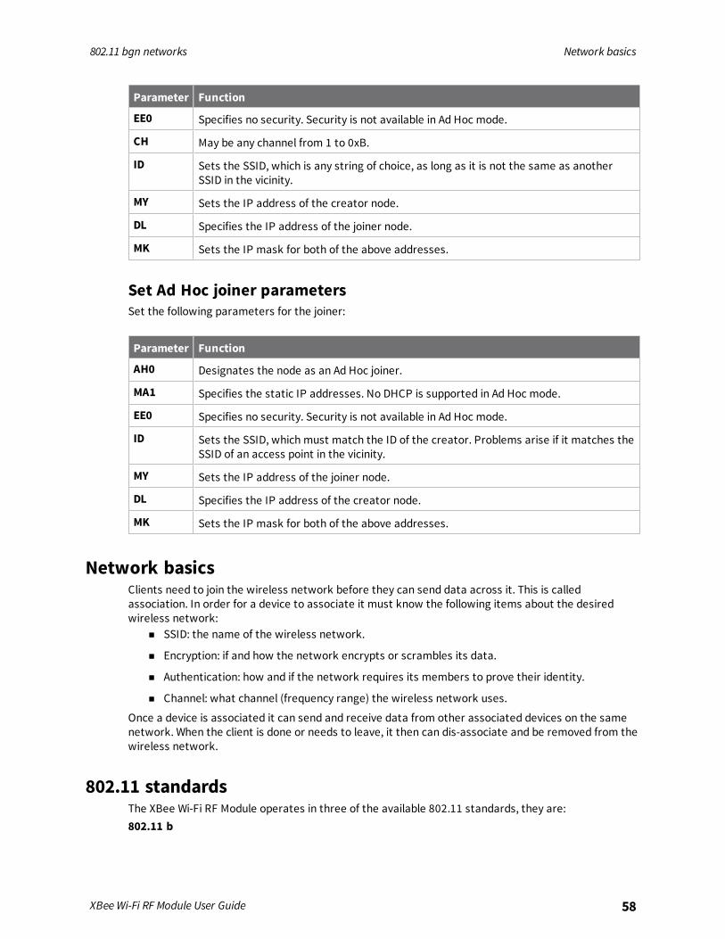
802.11 bgn networks Network basics
XBee Wi-Fi RF Module User Guide 58
Parameter Function
EE0 Specifies no security. Security is not available in Ad Hoc mode.
CH May be any channel from 1 to 0xB.
ID Sets the SSID, which is any string of choice, as long as it is not the same as anotherSSID in the vicinity.
MY Sets the IP address of the creator node.
DL Specifies the IP address of the joiner node.
MK Sets the IP mask for both of the above addresses.
Set Ad Hoc joiner parametersSet the following parameters for the joiner:
Parameter Function
AH0 Designates the node as an Ad Hoc joiner.
MA1 Specifies the static IP addresses. No DHCP is supported in Ad Hoc mode.
EE0 Specifies no security. Security is not available in Ad Hoc mode.
ID Sets the SSID, which must match the ID of the creator. Problems arise if it matches theSSID of an access point in the vicinity.
MY Sets the IP address of the joiner node.
DL Specifies the IP address of the creator node.
MK Sets the IP mask for both of the above addresses.
Network basicsClients need to join the wireless network before they can send data across it. This is calledassociation. In order for a device to associate it must know the following items about the desiredwireless network:
n SSID: the name of the wireless network.
n Encryption: if and how the network encrypts or scrambles its data.
n Authentication: how and if the network requires its members to prove their identity.
n Channel: what channel (frequency range) the wireless network uses.
Once a device is associated it can send and receive data from other associated devices on the samenetwork. When the client is done or needs to leave, it then can dis-associate and be removed from thewireless network.
802.11 standardsThe XBee Wi-Fi RF Module operates in three of the available 802.11 standards, they are:802.11 b

802.11 bgn networks Encryption
XBee Wi-Fi RF Module User Guide 59
The 802.11b standard was approved in July 1999 and can be considered the second generation.802.11b operates in the 2.4 GHz frequency ISM band. The data rate is from 1 to 11 Mb/s.802.11 gThe 802.11g standard was approved in 2003. It provides a maximum data rate of 54 Mb/s. In addition,the standard is also fully backwards-compatible with existing 802.11b wireless networks.802.11 nThe 802.11n standard was approved in 2009. It provides for data rates up to 300 Mb/s. The XBee Wi-Fimodule uses the single stream nmode with 20 MHz bandwidth and is capable of up to 72.2 Mb/s overthe air in n mode.
EncryptionEncryption is a method of scrambling a message that makes it unreadable to unwanted parties,adding a degree of secure communications. There are different protocols for providing encryption, andthe XBee Wi-Fi RF Module supports WPA, WPA2, andWEP.
AuthenticationAuthentication deals with proving the identity of the wireless device attempting to associate with thenetwork. There are different methods of doing this. The XBee Wi-Fi RF Module supports Open andShared Key authentication in WEP mode and it only supports shared key authentication in WPA andWPA2 modes.
Open authenticationOpen authentication is when the access point simply accepts the wireless devices identity withoutverifying or proving it. The benefits to this are simplicity and compatibility (all devices can do it). In thismode, which is only available when using WEP, a connection to the access point occurs even if the WEPkey is wrong. However, no real communication can occur because of mismatched keys. If DHCP isconfigured, it fails too, causing the AI indicator to get stuck in the AI 41 state.If, on the other hand, the AP is configured for shared key authentication, no connection occurs with anincorrect WEP key. Instead, AI gets stuck in the FF state, indicating scanning. Although shared keyauthentication sounds better, it exposes a big security flaw with WEP. The challenge text, itsencrypted result, and a success/failure result are passed in the clear and can easily be caught over theair to determine the WEP key.
Shared KeyShared Key is when the wireless devices must present the proper key to get on the network. AlthoughShared Key has more security than Open authentication it should not be considered secure. One ofthe benefits of Shared Key authentication is simplicity.
ChannelsThe XBee Wi-Fi RF Module operates in the 2412 - 2472 MHz range. The frequency range is brokendown into thirteen channels. Data is transmitted on a channel by radio frequencies over a certainfrequency range. In order to avoid bad performance caused by the overlapping (collision) of channelfrequencies in a wireless LAN environment, it is very important that you select the channels ofneighboring access points accordingly.

802.11 bgn networks Channels
XBee Wi-Fi RF Module User Guide 60
The center frequencies of the thirteen possible channels range from 2412 to 2472 MHz, with eachchannel being 22 MHz wide and centered in 5 MHz intervals. This means that only 3 channels (1, 6, and11) in North America are not subject to overlapping.

IP services
The XBee Wi-Fi RF Module provides services using Internet Protocol (IP) for XBee and other clients onthe network. IP services provide functionality to allow XBee device configuration and direct serial portaccess. There are two XBee services:
XBee Application Service 62Serial Communication Service 68
XBee Wi-Fi RF Module User Guide 61
IP services XBee Application Service
XBee Wi-Fi RF Module User Guide 62
XBee Application ServiceThis service primarily provides for XBee device configuration. It also provides API compatibility forcustomers who have designed around other XBee devices. It uses UDP to transfer packets to andfrom port number 0xBEE. Packets are optionally acknowledged by the service but retries are notavailable. An extra header is added to the packet data to define commands for configuration andserial data transfer.Access the service from a local host or network client. Use C0 (Serial Communication Service Port)and DE command to configure the source and destination ports for the serial communication service.The XBee application service uses hard coded port 0xBEE for both source and destination and there isno option to configure another port.
Note Do not configure C0 and/or DE to 0xBEE to use the XBee Application Service. Doing so causes anerror (AI = 42), and the transceiver will neither send nor receive data.
Local host accessFrom a local host, access XBee Application Service using API frames. There are remote AT commandframes as well as transmission frames. The API frames are:
n TX (Transmit) Request: 64-bit - 0x00
n Rx (Receive) Packet: 64-bit - 0x80 (This frame is generated by the XBee Wi-Fi RF Module)
n Remote AT Command Request - 0x07
n General Purpose Memory command (Access General Purpose Flash Memory)
TX64 and RX64 API framesThe transmit and receive 64-bit API frames provide a standardized set of API frames to use for a pointto multipoint network—a closed network of XBee Wi-Fi RF Modules. The format of these frames isstandardized to work with other XBee products, such as the API frames of the 802.15.4 device.
Note The XBee Wi-Fi RF Module cannot communicate with an XBee 802.15.4 module.
Transmit and receive data
Transmit dataThe local host uses the TX64 frame to send data to another XBee device using this service. When thedevice receives the frame through the serial port it converts the contents of the frame to a serial datatransfer command as defined by the XBee Application Service.
Receive dataA received serial data transfer command goes to the serial port. The serial port's mode determinesthe data format. When in API mode, the data is sent to the host using the RX 64-bit frame.
Note We do not recommended using this service to send data to a network client. Use the serialcommunication service.
Change configuration on a remote deviceUse the Remote AT command frame to change configuration on a remote device. See Remote ATCommand Request - 0x07 for more information.

IP services XBee Application Service
XBee Wi-Fi RF Module User Guide 63
Update the firmwareTo perform firmware updates from the local host, send Zigbee explicit API frames (type 0x11) to the IPaddress of the desired node with cluster ID 0x23. For details about the sequence of operations tofollow for firmware updates, see Update the firmware over-the-air.Zigbee Explicit Transmit Packet - 0x11 has this name because it has fields that are uniquely Zigbee,such as endpoint and cluster ID. To perform firmware updates the same on all XBee devices, we chosethis frame type, even though all XBee devices (including the XBee Wi-Fi RF Module) do not support theZigbee standard.The XBee Wi-Fi RF Module also supports other Zigbee frame types. These are frame types 0x10, 0x17,0x8B, 0x90, 0x91, and 0x97. These frame types do not allow XBee Wi-Fi RF Modules to execute theZigbee protocol and they do not allow OTA compatibility between the two protocols. If you want toimplement these API frame types on your host program, you can continue to use them, even with theXBee Wi-Fi RF Module. If you are developing a new host program for the XBee Wi-Fi RF Module, youshould not use these frame types because the WiFi frame types (0x20, and 0xB0) make more senseand have less API overhead.Frame 0x11 is required across all protocols for firmware updates.
Network client accessTo access this port, send a packet from the client using the UDP protocol on port 0xBEE. Data sent tothis port must have an additional header preceding the data. See the following table for the header'sdescription.
Field name OffsetFieldlength Description
Number1 0 2 Can be any random number
Number2 2 2 Number1 ^ 0x4242 (Exclusive OR of Number1 and constant0x4242)
PacketID 4 1 Reserved for later use (0 for now)
EncPad 5 1 Reserved for later use (0 for now)
Command ID 6 1 0x00 = Data0x02 = Remote Command0x03 = General Purpose Memory Command0x04 = I/O Sample0x80 = Data Acknowledgment0x82 = Response to remote command0x83 = Response to General Purpose Memory Command
Commandoptions
7 1 bit 0 – encrypted if set (Reserved for later use)bit 1 – set to request an ACKbits 2:7 - unused (Set to 0 for forward compatibility.)
All of the commands and command responses that follow are preceded with this application header.

IP services XBee Application Service
XBee Wi-Fi RF Module User Guide 64
Send configuration commandsA network client can send AT commands to the XBee Wi-Fi RF Module. The following packet structuredemonstrates how to query the SSID from a network client:
Packet fields Offset Example Description
Application header Number1 0 0x4242
Number2 2 0x0000 Number1 ^ Number2 = 0x4242.
Packet ID 4 0x00 Reserved for later use (0 for now).
Encryptionpad
5 0x00
Command ID 6 0x02 Indicates remote AT command.
Commandoptions
7 0x00 Options are not available for this command.
Command-specific data
Frame ID 8 0x01
Configurationoptions
9 0x02 0 – Queue command parameter. Must sendAC command or use apply changes option toapply changes.2 – Apply changes to all changed commands.
AT command 10 0x49 (I) Command Name - Two ASCII charactersthat identify the AT command.
11 0x44(D)
Parametervalue
12 If present, indicates the requestedparameter value to set the given command.If no characters present, command isqueried.
The response is sent back to the host with the following bytes.
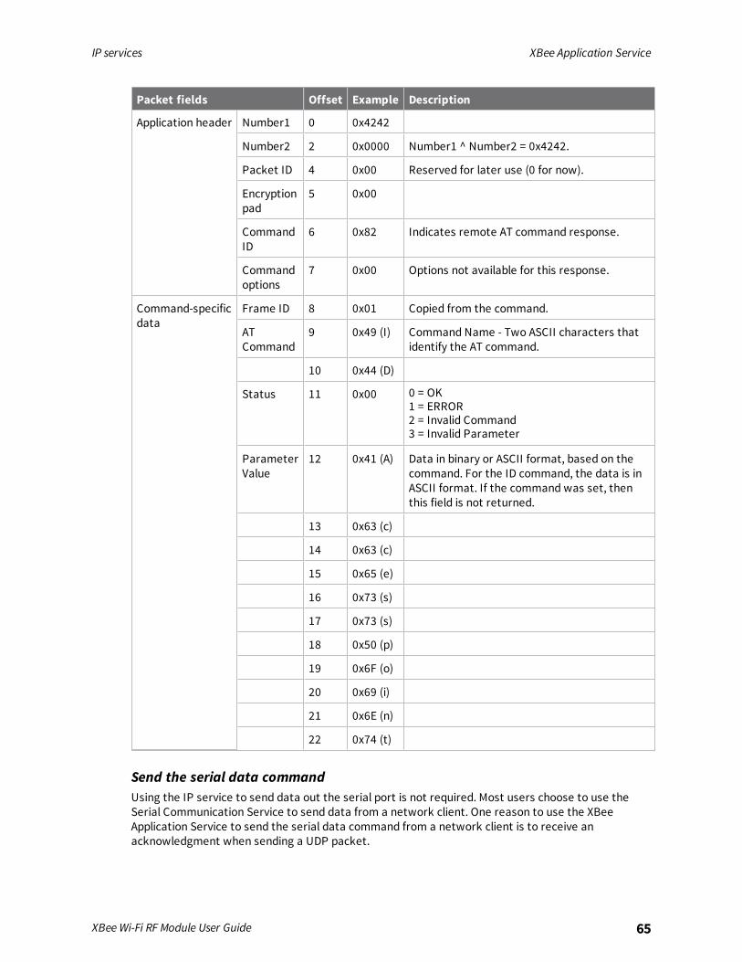
IP services XBee Application Service
XBee Wi-Fi RF Module User Guide 65
Packet fields Offset Example Description
Application header Number1 0 0x4242
Number2 2 0x0000 Number1 ^ Number2 = 0x4242.
Packet ID 4 0x00 Reserved for later use (0 for now).
Encryptionpad
5 0x00
CommandID
6 0x82 Indicates remote AT command response.
Commandoptions
7 0x00 Options not available for this response.
Command-specificdata
Frame ID 8 0x01 Copied from the command.
ATCommand
9 0x49 (I) Command Name - Two ASCII characters thatidentify the AT command.
10 0x44 (D)
Status 11 0x00 0 = OK1 = ERROR2 = Invalid Command3 = Invalid Parameter
ParameterValue
12 0x41 (A) Data in binary or ASCII format, based on thecommand. For the ID command, the data is inASCII format. If the command was set, thenthis field is not returned.
13 0x63 (c)
14 0x63 (c)
15 0x65 (e)
16 0x73 (s)
17 0x73 (s)
18 0x50 (p)
19 0x6F (o)
20 0x69 (i)
21 0x6E (n)
22 0x74 (t)
Send the serial data commandUsing the IP service to send data out the serial port is not required. Most users choose to use theSerial Communication Service to send data from a network client. One reason to use the XBeeApplication Service to send the serial data command from a network client is to receive anacknowledgment when sending a UDP packet.
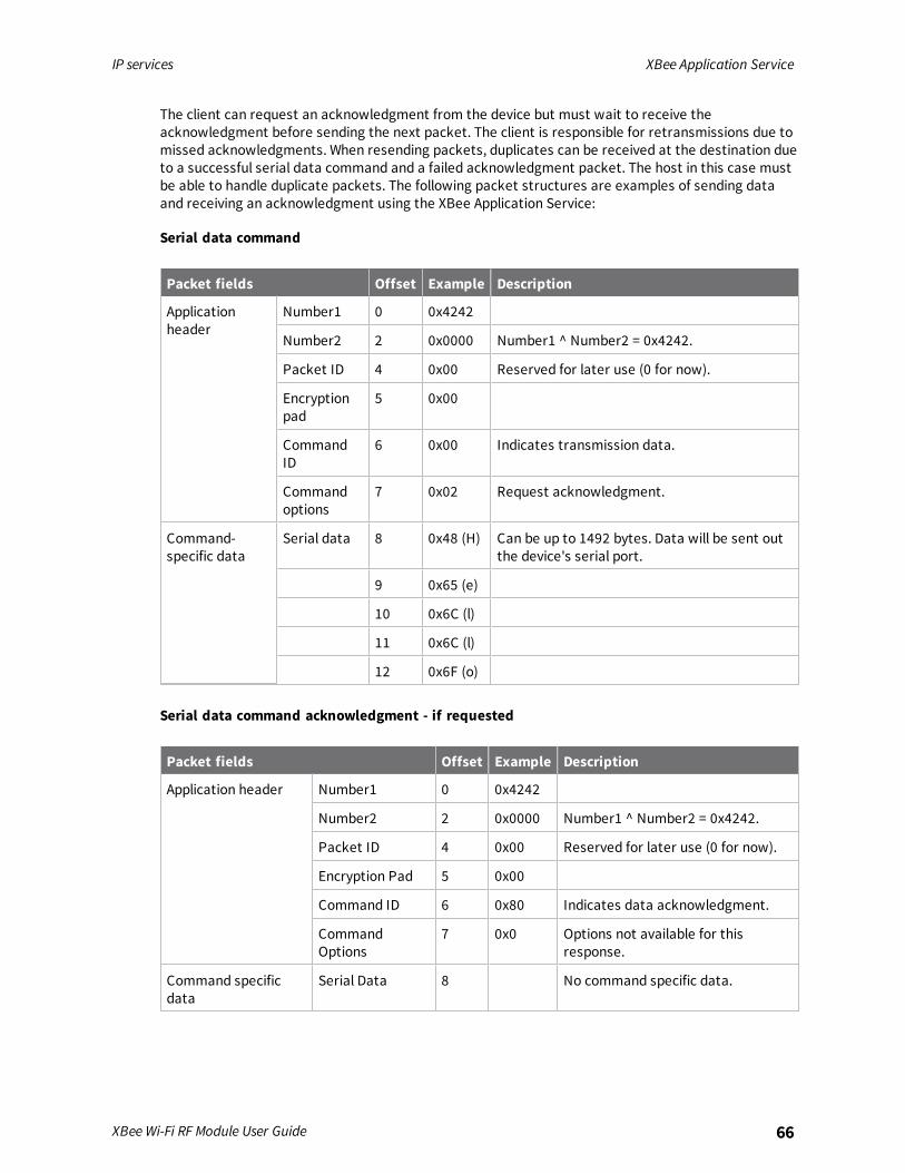
IP services XBee Application Service
XBee Wi-Fi RF Module User Guide 66
The client can request an acknowledgment from the device but must wait to receive theacknowledgment before sending the next packet. The client is responsible for retransmissions due tomissed acknowledgments. When resending packets, duplicates can be received at the destination dueto a successful serial data command and a failed acknowledgment packet. The host in this case mustbe able to handle duplicate packets. The following packet structures are examples of sending dataand receiving an acknowledgment using the XBee Application Service:
Serial data command
Packet fields Offset Example Description
Applicationheader
Number1 0 0x4242
Number2 2 0x0000 Number1 ^ Number2 = 0x4242.
Packet ID 4 0x00 Reserved for later use (0 for now).
Encryptionpad
5 0x00
CommandID
6 0x00 Indicates transmission data.
Commandoptions
7 0x02 Request acknowledgment.
Command-specific data
Serial data 8 0x48 (H) Can be up to 1492 bytes. Data will be sent outthe device's serial port.
9 0x65 (e)
10 0x6C (l)
11 0x6C (l)
12 0x6F (o)
Serial data command acknowledgment - if requested
Packet fields Offset Example Description
Application header Number1 0 0x4242
Number2 2 0x0000 Number1 ^ Number2 = 0x4242.
Packet ID 4 0x00 Reserved for later use (0 for now).
Encryption Pad 5 0x00
Command ID 6 0x80 Indicates data acknowledgment.
CommandOptions
7 0x0 Options not available for thisresponse.
Command specificdata
Serial Data 8 No command specific data.

IP services XBee Application Service
XBee Wi-Fi RF Module User Guide 67
Receive I/O sample dataSample data generated by the device is sent to the address configured by the DL commands. Thisdata can be sent to another XBee device or to a network client. It is sent using UDP from the 0xBEEport as with other XBee Application services. Sample data is received by the client as follows:
Frame fields Offset Example Description
Application header Number1 0 0x4242
Number2 2 0x0000 Number1 ^ Number2 = 0x4242.
Packet ID 4 0x00 Reserved for later use (0 for now).
Encryptionpad
5 0x00
CommandID
6 0x04 Indicates I/O sample data.
Commandoptions
7 0x00 Options not available for this response.
Command-specificdata
Number ofSamples
8 0x01 Indicates one sample set.
DigitalMask
MSB 9 0x01 Bit Mask. Each bit represents an enabled DIOline starting with DIO0 at bit 0.
LSB 10 0x01
AnalogMask
11 0x02 Bit Mask. Each bit represents an enabled ADCstarting with ADC0 at bit 0. This selects ADC1for analog sampling.
DigitalSample
MSB12
0x00 This field is only present if at least one DIO lineis enabled in the digital mask specified above.Each bit represents a DIO line. Start with bit 0for DIO0.
LSB 13 0x01
AnalogSample
MSB14
0x02 0x200 indicates that reading is half of VREF.For a default VREF of 2.5 V, 0x200 represents1.25 volts on ADC1 in this example.
LSB 15 0x00
Send over-the-air firmware updatesA network client can also use the XBee IP services to send a firmware update to the device. This isdone by sending a frame formatted with an application header, followed by a GPM header, followed byGPM data. The format of the application header is provided in Network client access. See GeneralPurpose Flash Memory for details about GPM headers format options. Make sure each GPM header ispreceded by an application header. The following table shows an example of the final step of afirmware update process.

IP services Serial Communication Service
XBee Wi-Fi RF Module User Guide 68
Packet fields Offset Example Description
Applicationheader
Number1 0 0x4242 This is an easy number to create anaccepted frame.
Number2 2 0x0000 Number1 ^ Number2 = 0x4242 (This is aneasy way to send a frame that software willnot reject).
Packet ID 4 0x00 Reserved for later use (0 for now).
EncPad 5 0x00
Command ID 6 0x03 General Purpose Memory Command.
Command Options 7 0x00 Do not request an acknowledgment.
Command-specific data
GPM_CMD_ID 8 0x06 Firmware verify and install command.
GPM_OPTIONS 9 0x00 Reserved for later use (0 for now).
GPM_BLOCK_NUM
10 0x00
GPM_START_INDEX
12 0x00
GPM_NUM_BYTES 14 0x0000
GPM_DATA 16 This field is unused for this command.
Serial Communication ServiceThe Serial Communication Service connects an IP port to the serial peripheral (UART or SPI) of theXBee Wi-Fi RF Module. No additional formatting or header is required and data is transferred betweenthe RF hardware and Serial Communication hardware as received.Use C0 (Serial Communication Service Port) and DE command to configure the IP ports. Port 0xBEE isreserved for the XBee Application Service and should not be used for the Serial CommunicationService. The behavior of this service varies based on the mode of the serial port.
Transparent modeIn Transparent mode, only one port is available, and that port may be either UDP or TCP depending onthe configuration specified in IP (IP Protocol). Data received on the serial port is packetized and sentto the RF port and data received on the RF port is sent to the serial port without any formatting of thedata. For details about how data is packetized, see Transparent operating mode.
UDPWhen IP (IP Protocol) is configured for User Datagram Protocol (UDP), serial data is sent to the IPaddress specified by DL command and it is sent to the UDP port specified by DE command. The sourceof the packet is defined by C0 (Serial Communication Service Port). No connection is established

IP services Serial Communication Service
XBee Wi-Fi RF Module User Guide 69
TCPWhen IP (IP Protocol) is configured for Transmission Control Protocol (TCP), only one connection isallowed at a time. If a transmission is attempted while a TCP connection exists, the data is sent onthat connection, ignoring the DL command and DE command parameters. This connection can beinitiated by a local host or by a network client.A local host initiates a connection by sending data to the serial port. A connection is created based onthe DL and DE commands. However, if DL is a broadcast address, then UDP is used, ignoring the TCPconfiguration.A network client establishing a TCP connection to the XBee Wi-Fi RF Module uses the port defined byC0 (Serial Communication Service Port). When established, any data sent by the local host does notcreate a new connection based on DL and DE, but rather uses the existing connection.
API modeAPI mode allows you to specify the protocol (UDP or TCP) destination address, destination port, andsource port for transmission.
UDP modeIf you specify UDP mode in the Transmit (TX) Request: IPv4 - 0x20, no connection is made to thedestination address and port. Instead, the data is packetized and sent directly, providing the sourceport matches the local port specified by C0 (Serial Communication Service Port).
TCP modeIn API mode, multiple TCP connections are allowed simultaneously. A TCP connection is fully definedby these four entities:
n Local IP address
n Local port number
n Remote IP address
n Remote port number
When an Transmit (TX) Request: IPv4 - 0x20 is sent to the device, it specifies a destination address andport. To send data on an existing TCP connection, the destination address and port given in the APIframe must match the remote address and port of an existing TCP connection. The search for amatching connection ignores the source port number given in the API frame. This means that only oneTCP connection is allowed per remote port.The source port matters in the event that a matching TCP connection is not found. If it is 0, then anattempt is made to create a new connection prior to sending the data. If not, the data is dropped withan error.For purposes of the following discussion, a client requests a TCP connection of a server and a serveraccepts a TCP connection request from a client.As a client, the best strategy is to specify a source port of 0 and a destination port to match thelistening socket [C0 (Serial Communication Service Port)] of the receiving device or the server port forany other network device. This way, if a connection is not found, a new one is created.As a server, the best strategy is to swap the source and destination ports found in the IPv4 receivepacket and place them in the response, which is an IPv4 transmit packet. This allows the response tobe sent back on the same socket as the received data. If the data is sent to the listening socket of theother device rather than to the source socket given in the IPv4 receive packet, then an extra socket iscreated. While this still works, it unnecessarily creates an extra socket connection.
I/O support
The following topics describe analog and digital I/O line support, line passing and output control.
Analog and digital I/O lines 71Configure I/O functions 72I/O sampling 73Queried sampling 74Periodic I/O sampling 74Change detection sampling 75RSSI PWM 75
XBee Wi-Fi RF Module User Guide 70

I/O support Analog and digital I/O lines
XBee Wi-Fi RF Module User Guide 71
Analog and digital I/O linesXBee Wi-Fi RF Module firmware supports a number of analog and digital I/O pins that are configuredthrough software commands. You can set or query analog and digital I/O lines. The following tables listthe configurable I/O pins and the corresponding configuration commands.
Through-hole device
Pin names Device pin AT command Command range Default value
DIO1/AD1/ SPI_ATTN 19 D1 0-5 0
DIO2/AD2/SPI_CLK 18 D2 0-5 0
DIO3/AD3/SPI_SSEL 17 D3 0-5 0
DIO4/SPI_MOSI 11 D4 0-1, 3-5 0
DIO5/ASSOCIATE 15 D5 0-1, 3-5 1
DIO6/RTS 16 D6 0-1, 3-5 0
DIO7/CTS 12 D7 0-1, 3-7 1
DIO8/DTR/SLEEP_RQ 9 D8 0-1, 3-5 1
DIO9/On_SLEEP 13 D9 0-1, 3-5 1
DIO10/RSSI PWM/PWM0 6 P0 0-5 1
DIO11/PWM1 7 P1 0, 2-5 0
DIO12/SPI_MISO 4 P2 0-1, 3-5 0
DIO13/DOUT 2 P3 0-1 1
DIO14/DIN/CONFIG 3 P4 0-1 1
Surface-mount device
Pin names Device pin AT command Command range Default value
DIO1/AD1 32 D1 0, 2-5 0
DIO2/AD2 31 D2 0, 2-5 0
DIO3/AD3 30 D3 0, 2-5 0
DIO4 24 D4 0, 3-5 0
DIO5/ASSOCIATE 28 D5 0-1, 3-5 1
DIO6/RTS 29 D6 0-1, 3-5 0
DIO7/CTS 25 D7 0-1, 3-7 1
I/O support Configure I/O functions
XBee Wi-Fi RF Module User Guide 72
Pin names Device pin AT command Command range Default value
DIO8/DTR/SLEEP_RQ 10 D8 0-1, 3-5 1
DIO9/On_SLEEP 26 D9 0-1, 3-5 1
DIO10/RSSI PWM/PWM0 7 P0 0-5 1
DIO11/PWM1 8 P1 0, 2-5 0
DIO12 5 P2 0, 3-5 0
DIO13/DOUT 3 P3 0-1 1
DIO14/DIN/CONFIG 4 P4 0-1 1
DIO15/SPI_MISO 17 P5 0-1, 4-5 1
DIO16/SPI_MOSI 16 P6 0-1, 4-5 1
DIO17/SPI_SSEL 15 P7 0-1, 4-5 1
DIO18/SPI_CLK 14 P8 0-1, 4-5 1
DIO19/SPI_ATTN 12 P9 0-1, 4-6 1
Configure I/O functionsTo enable an analog or digital I/O function on one or more device pin(s):
1. Issue the appropriate configuration command with the correct parameter.
2. Apply the changes on the device for the I/O settings to take effect.
You can use PR (Pull-up Resistor) to set pull-up/down resistors for each digital input line. The PR valueenables or disables the pull-up/down resistors, and PD (Pull Direction) determines if a pull-up or pull-down is used. Internal pull-up/down resistors are not available for digital output pins, analog inputpins, or for disabled pins.
Pin command parameter Description
0 Disabled
1 Peripheral control
2 Analog input or PWM output
3 Data in monitored
4 Data out default low
5 Data out default High
6 RS-485 enable low
7 RS-485 enable high
>7 Unsupported

I/O support I/O sampling
XBee Wi-Fi RF Module User Guide 73
I/O samplingThe XBee Wi-Fi RF Module has the ability to monitor and sample the analog and digital I/O lines. I/Osamples indicate the current state of I/O lines. These samples may be output on the local (serial) port,transmitted to a remote device, or sent to Remote Manager.There are three ways to obtain I/O samples, either locally or remotely:
n Queried sampling
n Periodic sampling
n Change detection sampling
I/O sample data is formatted as shown in following table.
Bytes Name Description
1 Sample Sets Number of sample sets in the packet. Always set to 1.
2 Digital channel mask Digital I/O line on the device.bit 0 = DIO0bit 1 = DIO1bit 2 = DIO2bit 3 = DIO3bit 4 = DIO4bit 5 = DIO5bit 6 = DIO6bit 7 = DIO7bit 8 = DIO8bit 9 = DIO9bit 10 = DIO10bit 11 = DIO11bit 12 = DIO12For example, a digital channel mask of 0x002F means DIO0 1, 2, 3,and 5 are enabled as digital I/O.
1 Analog channelmask
Indicates which lines have analog inputs enabled for sampling.Each bit in the analog channel mask corresponds to one analoginput channel.bit 0 = AD0bit 1 = AD1bit 2 = AD2bit 3 = AD3
Variable Sampled data set If any digital I/O lines are enabled, the first two bytes of the dataset indicate the state of all enabled digital I/O. Only digitalchannels that are enabled in the Digital channel mask bytes haveany meaning in the sample set. If no digital IO is enabled on thedevice, these two bytes will be omitted.Following the digital I/O data (if any), each enabled analog channelwill return two bytes. The data starts with AD0 and continuessequentially for each enabled analog input channel up to AD3.
The sampled data set includes two bytes of digital I/O data only if one or more I/O lines on the deviceare configured as digital I/O. If no pins are configured as digital I/O, these two bytes are omitted.The digital I/O data is only relevant if the same bit is enabled in the digital I/O mask.

I/O support Queried sampling
XBee Wi-Fi RF Module User Guide 74
Analog samples are 10 bit values and aligned on a 16 bit boundary. The analog reading is scaled suchthat 0x0000 represents 0 V, and 0x3FF = VREF. VREF may be either 1.25 V or 2.5 V based on the settingof AV (Analog Voltage Reference), where 2.5 V is the default. The analog inputs on the device arecapped at 0x3FF. Analog samples are returned in order starting with AD0 and finishing with AD3. Onlyenabled analog input channels return data as shown in the example below.To convert the A/D reading to mV, do the following:
AD (mV) = (A/D reading (converted to decimal) * VREF) / 1023 where VREF may be 1250 or 2500Assuming that AV is set to the default value, the reading in the sample frame represents voltageinputs of 2385.14 mV (0x3D0) and 713.59 mV (0x124) for AD0 and AD1 respectively.
Queried samplingIS command can be sent to a device locally, or to a remote device using Remote AT Command Request- 0x07. When the IS command is sent and at least one I/O line is enabled as an input or an output, thereceiving device samples all enabled digital I/O and analog input channels and returns an I/O sample.When no I/O line is enabled, IS returns an error. If IS is sent locally, the I/O sample is sent out theUART or SPI port. If the IS command was received as a remote command, the I/O sample is sent over-the-air to the device that sent the IS command.If the IS command is issued in Commandmode, the device returns a carriage return-delimited listcontaining the above-listed fields. If the IS command is issued in API mode, the device returns an APIcommand response packet with the I/O data included in the command data portion of the responseframe.The following table shows an example of the fields in an IS response.
Example Sample AT response
0x01 [1 sample set]
0x0C0C [Digital Inputs: DIO 2, 3, 10, 11 selected]
0x03 [Analog Inputs; A/D 0,1]
0x0408 [Digital input states: DIO 3,10 high, DIO 2,11 low]
0x03D0 [Analog input ADIO 0=0x3D0]
0x0124 [Analog input ADIO 1=0x120]
Periodic I/O samplingPeriodic sampling allows the XBee Wi-Fi RF Module to take an I/O sample and transmit it to a remotedevice at a periodic rate. The periodic sample rate is set by IR (I/O Sample Rate). If IR is set to 0 orthere are no active I/O lines, periodic sampling is disabled. For all other values of IR, data is sampledafter IRmilliseconds have elapsed and transmitted to a remote device. However, the device cannotkeep up with transmitting an I/O sample more often than every three milliseconds. Therefore, whenIR is set to 1 or 2, many samples are lost.When Remote Manager is enabled (see Network commands), samples are sent as a data stream. SeeTransparent mode data to learn how to view the data streams. When DO bits 0 and 3 are both set(0x09), I/O samples are sent to the Remote Manager and to DL.When Remote Manager is not enabled, the I/O sample is sent to the address specified by DLcommand. When DL points to another device, that device must have API mode enabled. Otherwise,the data is dropped by the receiving device and is not sent out the serial port.
I/O support Change detection sampling
XBee Wi-Fi RF Module User Guide 75
When DL points to a network client, the I/O sample is sent to that network client. See Network clientaccess for the format of I/O samples sent to a network client.IR can be used with sleep. A device transmits periodic I/O samples at the IR rate until the deviceresumes sleeping. Even if the IR rate is set longer than the ST defined wake time, at least one I/Osample is still sent before the device returns to sleep because it sends one immediately upon wakeup. If it is not desired that a sample is sent every wake cycle, IF (Sample from Sleep Rate) can be usedto configure how many wake cycles should elapse before sending I/O samples at the IR rate.
Change detection samplingDevices can be configured to transmit a data sample immediately whenever a monitored digital I/Opin changes state. Change detect sampling cannot be triggered by an enabled analog input. IC (DigitalChange Detection) is a bitmask that can be used to set which digital I/O lines should be monitored fora state change. If one or more bits in IC is set, an I/O sample is transmitted as soon as a state changeis observed in one of the monitored digital IO lines. Change detection samples are transmitted to theIPv4 address specified by DL command, to Remote Manager, or to both, depending on the setting ofDO command. Viewing I/O samples on the remote device or Remote Manager is the same for changedetect sampling as it is for periodic sampling.
ExampleConfigure the following I/O settings on the XBee Wi-Fi RF Module:
1. To configure DIO1/AD1 as a digital input, issue D1 (DIO1/AD1 Configuration) with a parameterof 3 (ATD13).
2. To enable pull-up resistors on the same pin, issue PR (Pull-up Resistor) with bit 3 set (forexample ATPR8, ATPR1FFF, and so forth).
3. To configure DIO2/AD2 as an analog input, issue D2 (DIO2/AD2 Configuration) with a parameterof 2 to enable the analog input (ATD22).
4. To configure DIO4 as a digital output, driving high, issue D4 (DIO4/AD4 Configuration) with aparameter value of 5 (ATD45).
5. After issuing these commands, apply the changes so the device's I/O pins update to the newstates. Issue AC (Apply Changes) or CN command to apply the changes.
RSSI PWMThe XBee Wi-Fi RF Module features an RSSI/PWM pin (TH pin 6/SMT pin 7) that, if enabled, adjusts thePWM output to indicate the signal strength of the last received packet. Use P0 (DIO10 Configuration)to enable the RSSI pulse width modulation (PWM) output on the pin. If P0 is set to 1, the RSSI/PWM pinoutputs a PWM signal where the frequency is adjusted based on the received signal strength of thelast packet.When a data packet is received, if P0 is set to enable the RSSI/PWM feature, the RSSI PWM output isadjusted based on the link margin of the last packet. The RSSI/PWM output is enabled for a timebased on RP (RSSI PWM Timer). Each time an RF packet is received, the RSSI/PWM output is adjustedbased on the link margin of the new packet, and the RSSI timer is reset. If the RSSI timer expires, theRSSI/PWM pin is driven low. RP is measured in 100 ms units and defaults to a value of 40 (4 seconds).If running on the XBIB development board, DIO10 is connected to the RSSI LEDs, which may beinterpreted as follows:

I/O support RSSI PWM
XBee Wi-Fi RF Module User Guide 76
PWM duty cycle Number of LEDs turned on Link margin
79.39% or more 3 30 db or more
62.42% to 79.39% 2 20 db to 30 db
45.45% to 62.42% 1 10 db to 20 db
Less than 45.45% 0 Less than 10 db or no reception for RP time
Wi-Fi Protected Setup (WPS)
The XBee Wi-Fi RF Module may be configured using Wi-Fi Protected Setup (WPS). WPS allows for easyestablishment of a secure wireless network because security parameters are learned from a nearbyaccess point without having to enter themmanually. The device only supports WPS with the pushbutton method. There are security concerns with using WPS with the pin method because the securityinformation is passed in the clear.
Enable WPS 78Use WPS 78Pre-shared key (PSK) mode security 78
XBee Wi-Fi RF Module User Guide 77
Wi-Fi Protected Setup (WPS) Enable WPS
XBee Wi-Fi RF Module User Guide 78
Enable WPSWPS is enabled by default, but it is disabled if SSID is configured [ID (SSID) is not NULL] or if the deviceis connected in Soft AP mode.To use WPS with the Commissioning button, enable it by configuring D0 (DIO0/AD0/ CB Configuration)to 1.
Use WPSTo invoke WPS:
1. Press the Commissioning button twice if D0 (DIO0/AD0/ CB Configuration) is set to 1.
or1. Enter CB2 to use the CB command command.
2. Then, you must press a corresponding WPS button on a nearby WPS-capable access point (AP) ,which allows the security parameters to be exchanged and the connection to the AP to occur.
Pre-shared key (PSK) mode securityPre-shared key (PSK) mode, also known as Personal mode, is designed for home and small officenetworks that do not require the complexity of an 802.1X authentication server. Each wirelessnetwork device encrypts the network traffic using a 256 bit key. You can enter this key either as astring of 64 hexadecimal digits, or as a passphrase of 8 to 63 printable ASCII characters. If you useASCII characters, the 256 bit key is calculated by applying the PBKDF2 key derivation function to thepassphrase, using the SSID as the salt and 4096 iterations of HMAC-SHA1.

General Purpose Flash Memory
General Purpose Flash Memory 80Work with flash memory 80Access General Purpose Flash Memory 80General Purpose Flash Memory commands 81Update the firmware over-the-air 88
XBee Wi-Fi RF Module User Guide 79
General Purpose Flash Memory General Purpose Flash Memory
XBee Wi-Fi RF Module User Guide 80
General Purpose Flash MemoryXBee Wi-Fi RF Modules provide 160 4096-byte blocks of flash memory that an application can read andwrite to. This memory provides a non-volatile data storage area that an application uses for manypurposes. Some common uses of this data storage include:
n Storing logged sensor data
n Buffering firmware update data for a host microcontroller
n Storing and retrieving data tables needed for calculations performed by a host microcontroller
The General Purpose Memory (GPM) is also used to store a firmware update file for over-the-airfirmware updates of the device itself.
Work with flash memoryWhen working with the General Purpose Memory, observe the following limitations:
n Flash memory write operations are only capable of changing binary 1s to binary 0s. Only theerase operation can change binary 0s to binary 1s. For this reason, you should erase a flashblock before performing a write operation.
n When performing an erase operation, you must erase the entire flash memory block—youcannot erase parts of a flash memory block.
n Flash memory has a limited lifetime. The flash memory on which the GPM is based is rated at20,000 erase cycles before failure. Take care to ensure that the frequency of erase/writeoperations allows for the desired product lifetime. Digi's warranty does not cover products thathave exceeded the allowed number of erase cycles.
n Over-the-air firmware upgrades erase the entire GPM. Any user data stored in the GPM will belost during an over-the-air upgrade.
Access General Purpose Flash MemoryThe GPM of a target node can be accessed from the XBee Wi-Fi RF Module's serial port or from a non-XBee network client.To access the GPM of a target node locally or over-the-air, send commands to the MEMORY_ACCESScluster ID (0x23) on the DIGI_DEVICE endpoint (0xE6) of the target node using explicit API frames.Explicit API frames have frame identifier 0x11. For a description of Explicit API frames, see Operate inAPI mode.Access from a non-XBee network client is performed by sending UDP frames to the target node onport 0x0BEE. The payload begins with an application header followed by the GPM header describedbelow. See Network client access to learn how to format the application header.Use the following header to generate a GPM command. Use it whether you use serial port access ornetwork client access. For network client access, an application header needs to precede the GPMheader. This section describes the perspective of serial port access, without the application header.Do not forget to precede each frame with an application header if you use a network client for GPMaccess.

General Purpose Flash Memory General Purpose Flash Memory commands
XBee Wi-Fi RF Module User Guide 81
Byte offsetin payload
Number ofbytes Field name General field description
0 1 GPM_CMD_ID Specific GPM commands are describedin detail in the topics that follow.
1 1 GPM_OPTIONS Command-specific options.
2 2* GPM_BLOCK_NUM The block number addressed in theGPM.. Ranges from 0 to 159 (0x9F).
4 2* GPM_START_INDEX The byte index within the addressedGPM block.
6 2* GPM_NUM_BYTES The number of bytes in the GPM_DATAfield, or in the case of a READ, thenumber of bytes requested.
8 varies GPM_DATA
* Specify multi-byte parameters with big-endian byte ordering.
When a device sends a GPM command to another device via a unicast, the receiving device sends aunicast response back to the requesting device's source endpoint specified in the request packet. Itdoes not send a response for broadcast requests. If the source endpoint is set to the DIGI_DEVICEendpoint (0xE6) or Explicit API mode is enabled on the requesting device, then the requesting nodeoutputs a GPM response as an explicit API RX indicator frame (assuming it has API mode enabled).The format of the response is similar to the request packet:
Byte offset inpayload
Number ofbytes Field name General field description
0 1 GPM_CMD_ID This field is the same as the requestfield.
1 1 GPM_STATUS Status indicating whether thecommand was successful.
2 2* GPM_BLOCK_NUM The block number addressed in theGPM.. Ranges from 0 to 159 (0x9F).
4 2* GPM_START_INDEX The byte index within the addressedGPM block.
6 2* GPM_NUM_BYTES The number of bytes in the GPM_DATA field.
8 varies GPM_DATA
* Specify multi-byte parameters with big-endian byte ordering.
General Purpose Flash Memory commandsThis section provides information about commands that interact with GPM:

General Purpose Flash Memory General Purpose Flash Memory commands
XBee Wi-Fi RF Module User Guide 82
PLATFORM_INFO_REQUEST (0x00)A PLATFORM_INFO_REQUEST frame can be sent to query details of the GPM structure.
Field name Command-specific description
GPM_CMD_ID Should be set to PLATFORM_INFO_REQUEST (0x00).
GPM_OPTIONS This field is unused for this command. Set to 0.
GPM_BLOCK_NUM This field is unused for this command. Set to 0.
GPM_START_INDEX This field is unused for this command. Set to 0.
GPM_NUM_BYTES This field is unused for this command. Set to 0.
GPM_DATA No data bytes should be specified for this command.
PLATFORM_INFO (0x80)When a PLATFORM_INFO_REQUEST command request has been unicast to a node, that node sends aresponse in the following format to the source endpoint specified in the requesting frame.
Field name Command-specific description
GPM_CMD_ID Should be set to PLATFORM_INFO (0x80).
GPM_STATUS A 1 in the least significant bit indicates an error occurred. All otherbits are reserved at this time.
GPM_BLOCK_NUM Indicates the number of GPM blocks available.
GPM_START_INDEX Indicates the size, in bytes, of a GPM block.
GPM_NUM_BYTES The number of bytes in the GPM_DATA field. For this command,this field will be set to 0.
GPM_DATA No data bytes are specified for this command.
ExampleA PLATFORM_INFO_REQUEST sent to a device with a serial number of 0x0013a200407402AC shouldbe formatted as follows (spaces added to delineate fields):
7E 001C 11 01 0013A200407402AC FFFE E6 E6 0023 C105 00 00 00 00 0000 0000 0000 24Assuming all transmissions were successful, the following API packets would be output the sourcenode's serial interface:
7E 0007 8B 01 FFFE 00 00 00 767E 001A 91 0013A200407402AC FFFE E6 E6 0023 C105 C1 80 00 0077 0200 0000 EB
ERASE (0x01)The ERASE command erases (writes all bits to binary 1) one or all of the GPM flash blocks. You can alsouse the ERASE command to erase all blocks of the GPM by setting the GPM_NUM_BYTES field to 0.
General Purpose Flash Memory General Purpose Flash Memory commands
XBee Wi-Fi RF Module User Guide 83
Field name Command-specific description
GPM_CMD_ID Should be set to ERASE (0x01).
GPM_OPTIONS There are currently no options defined for the ERASE command.Set this field to 0.
GPM_BLOCK_NUM Set to the index of the GPM block that should be erased. Whenerasing all GPM blocks, this field is ignored (set to 0).
GPM_START_INDEX The ERASE command only works on complete GPM blocks. Thecommand cannot be used to erase part of a GPM block. For thisreason GPM_START_INDEX is unused (set to 0).
GPM_NUM_BYTES Setting GPM_NUM_BYTES to 0 has a special meaning. It indicatesthat every flash block in the GPM should be erased (not just theone specified with GPM_BLOCK_NUM). In all other cases, theGPM_NUM_BYTES field should be set to the GPM flash block size.
GPM_DATA No data bytes are specified for this command.
ERASE_RESPONSE (0x81)When an ERASE command request has been unicast to a node, that node sends a response in thefollowing format to the source endpoint specified in the requesting frame.
Field name Command-specific description
GPM_CMD_ID Should be set to ERASE_RESPONSE (0x81).
GPM_STATUS A 1 in the least significant bit indicates an error occurred. Allother bits are reserved at this time.
GPM_BLOCK_NUM Matches the parameter passed in the request frame.
GPM_START_INDEX Matches the parameter passed in the request frame.
GPM_NUM_BYTES The number of bytes in the GPM_DATA field. For this command,this field will be set to 0.
GPM_DATA No data bytes are specified for this command.
ExampleTo erase flash block 42 of a target radio with serial number of 0x0013a200407402ac format an ERASEpacket as follows (spaces added to delineate fields):
7E 001C 11 01 0013A200407402AC FFFE E6 E6 0023 C105 00 C0 01 00 002A 0000 0200 37Assuming all transmissions were successful, the following API packets would be output the sourcenode's serial interface:
7E 0007 8B 01 FFFE 00 00 00 767E 001A 91 0013A200407402AC FFFE E6 E6 0023 C105 C1 81 00 002A 0000 0000 39
General Purpose Flash Memory General Purpose Flash Memory commands
XBee Wi-Fi RF Module User Guide 84
WRITE (0x02) and ERASE_THEN_WRITE (0x03)The WRITE command writes the specified bytes to the GPM location specified. Before writing bytes toa GPM block it is important that the bytes have been erased previously. The ERASE_THEN_WRITEcommand performs an ERASE of the entire GPM block specified with the GPM_BLOCK_NUM field priorto doing a WRITE.
Field name Command-specific description
GPM_CMD_ID Should be set to WRITE (0x02) or ERASE_THEN_WRITE (0x03).
GPM_OPTIONS There are currently no options defined for this command. Set thisfield to 0.
GPM_BLOCK_NUM Set to the index of the GPM block that should be written. Rangesfrom 0 to 159 (0x9F).
GPM_START_INDEX Set to the byte index within the GPM block where the given datashould be written.
GPM_NUM_BYTES Set to the number of bytes specified in the GPM_DATA field. If thecommand is ERASE_THEN_WRITE (0x03), the GPM is erasedbefore it is written. For the WRITE (0x02) command, the areabeing written should have previously been erased.
Note If this parameter is zero, the command erases the entireGPM and writes nothing.
Only one GPM block can be operated on per command. For thisreason, GPM_START_INDEX + GPM_NUM_BYTES cannot begreater than the GPM block size. The number of bytes sent in anexplicit API frame (including the GPM command fields) cannotexceed the maximum payload size of the device. The maximumpayload size can be queried with the NP command.
GPM_DATA The data to be written.
WRITE _RESPONSE (0x82) and ERASE_THEN_WRITE_RESPONSE (0x83)When a WRITE or ERASE_THEN_WRITE command request has been unicast to a node, that node sendsa response in the following format to the source endpoint specified in the requesting frame.
Field name Command-specific description
GPM_CMD_ID Should be set to WRITE_RESPONSE (0x82) or ERASE_THEN_WRITE_RESPONSE (0x83)
GPM_STATUS A 1 in the least significant bit indicates an error occurred. All otherbits are reserved at this time
GPM_BLOCK_NUM Matches the parameter passed in the request frame
GPM_START_INDEX Matches the parameter passed in the request frame

General Purpose Flash Memory General Purpose Flash Memory commands
XBee Wi-Fi RF Module User Guide 85
Field name Command-specific description
GPM_NUM_BYTES The number of bytes in the GPM_DATA field. For this command, thisfield will be set to 0
GPM_DATA No data bytes are specified for these commands
ExampleTo write 15 bytes of incrementing data to flash block 22 of a target radio with serial number of0x0013a200407402ac a WRITE packet should be formatted as follows (spaces added to delineatefields):
7E 002B 11 01 0013A200407402AC FFFE E6 E6 0023 C105 00 C0 02 00 0016 0000 000F0102030405060708090A0B0C0D0E0F C5
Assuming all transmissions were successful and that flash block 22 was previously erased, thefollowing API packets would be output the source node's serial interface:
7E 0007 8B 01 FFFE 00 00 00 767E 001A 91 0013A200407402AC FFFE E6 E6 0023 C105 C1 82 00 0016 0000 0000 4C
READ (0x04)You can use the READ command to read the specified number of bytes from the GPM locationspecified. Data can be queried from only one GPM block per command.
Field name Command-specific description
GPM_CMD_ID Should be set to READ (0x04).
GPM_OPTIONS There are currently no options defined for this command. Set thisfield to 0.
GPM_BLOCK_NUM Set to the index of the GPM block that should be read. Ranges from0 to 159 (0x9F).
GPM_START_INDEX Set to the byte index within the GPM block where the given datashould be read.
GPM_NUM_BYTES Set to the number of data bytes to be read. Only one GPM block canbe operated on per command. For this reason, GPM_START_INDEX +GPM_NUM_BYTES cannot be greater than the GPM block size. Thenumber of bytes sent in an explicit API frame (including the GPMcommand fields) cannot exceed the maximum payload size of thedevice. You can query the maximum payload size with the NP ATcommand.
GPM_DATA No data bytes should be specified for this command.
READ_RESPONSE (0x84)When a READ command request has been unicast to a node, that node sends a response in thefollowing format to the source endpoint specified in the requesting frame.
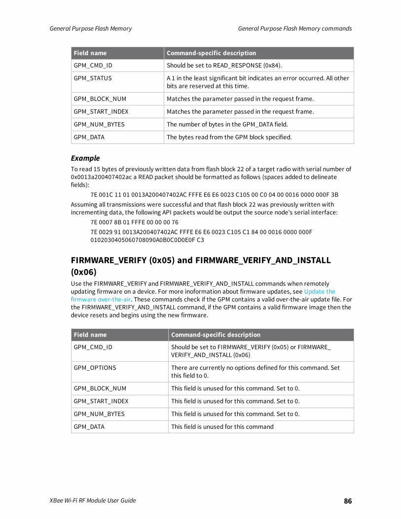
General Purpose Flash Memory General Purpose Flash Memory commands
XBee Wi-Fi RF Module User Guide 86
Field name Command-specific description
GPM_CMD_ID Should be set to READ_RESPONSE (0x84).
GPM_STATUS A 1 in the least significant bit indicates an error occurred. All otherbits are reserved at this time.
GPM_BLOCK_NUM Matches the parameter passed in the request frame.
GPM_START_INDEX Matches the parameter passed in the request frame.
GPM_NUM_BYTES The number of bytes in the GPM_DATA field.
GPM_DATA The bytes read from the GPM block specified.
ExampleTo read 15 bytes of previously written data from flash block 22 of a target radio with serial number of0x0013a200407402ac a READ packet should be formatted as follows (spaces added to delineatefields):
7E 001C 11 01 0013A200407402AC FFFE E6 E6 0023 C105 00 C0 04 00 0016 0000 000F 3BAssuming all transmissions were successful and that flash block 22 was previously written withincrementing data, the following API packets would be output the source node's serial interface:
7E 0007 8B 01 FFFE 00 00 00 767E 0029 91 0013A200407402AC FFFE E6 E6 0023 C105 C1 84 00 0016 0000 000F0102030405060708090A0B0C0D0E0F C3
FIRMWARE_VERIFY (0x05) and FIRMWARE_VERIFY_AND_INSTALL(0x06)Use the FIRMWARE_VERIFY and FIRMWARE_VERIFY_AND_INSTALL commands when remotelyupdating firmware on a device. For more inoformation about firmware updates, see Update thefirmware over-the-air. These commands check if the GPM contains a valid over-the-air update file. Forthe FIRMWARE_VERIFY_AND_INSTALL command, if the GPM contains a valid firmware image then thedevice resets and begins using the new firmware.
Field name Command-specific description
GPM_CMD_ID Should be set to FIRMWARE_VERIFY (0x05) or FIRMWARE_VERIFY_AND_INSTALL (0x06)
GPM_OPTIONS There are currently no options defined for this command. Setthis field to 0.
GPM_BLOCK_NUM This field is unused for this command. Set to 0.
GPM_START_INDEX This field is unused for this command. Set to 0.
GPM_NUM_BYTES This field is unused for this command. Set to 0.
GPM_DATA This field is unused for this command

General Purpose Flash Memory General Purpose Flash Memory commands
XBee Wi-Fi RF Module User Guide 87
FIRMWARE_VERIFY_RESPONSE (0x85)When a FIRMWARE_VERIFY command request has been unicast to a node, that node sends a responsein the following format to the source endpoint specified in the requesting frame.
Field name Command-specific description
GPM_CMD_ID Should be set to FIRMWARE_VERIFY_RESPONSE (0x85)
GPM_STATUS A 1 in the least significant bit indicates the GPM does not contain avalid firmware image. A 0 in the least significant bit indicates theGPM does contain a valid firmware image. All other bits arereserved at this time.
GPM_BLOCK_NUM This field is unused for this command. Set to 0.
GPM_START_INDEX This field is unused for this command. Set to 0.
GPM_NUM_BYTES This field is unused for this command. Set to 0.
GPM_DATA This field is unused for this command
FIRMWARE_VERIFY _AND_INSTALL_RESPONSE (0x86)When a FIRMWARE_VERIFY_AND_INSTALL command request has been unicast to a node, that nodesends a response in the following format to the source endpoint specified in the requesting frame onlyif the GPM memory does not contain a valid image. If the image is valid, the device resets and beginsusing the new firmware.
Field name Command-specific description
GPM_CMD_ID Should be set to FIRMWARE_VERIFY_AND_INSTALL_RESPONSE(0x86).
GPM_STATUS A 1 in the least significant bit indicates the GPM does not contain avalid firmware image. All other bits are reserved at this time.
GPM_BLOCK_NUM This field is unused for this command. Set to 0.
GPM_START_INDEX This field is unused for this command. Set to 0.
GPM_NUM_BYTES This field is unused for this command. Set to 0.
GPM_DATA This field is unused for this command.
ExampleTo verify a firmware image previously loaded into the GPM on a target device with serial number0x0013a200407402ac, format a FIRMWARE_VERIFY packet as follows (spaces added to delineatefields):
7E 001C 11 01 0013A200407402AC FFFE E6 E6 0023 C105 00 00 05 00 0000 0000 0000 1FAssuming all transmissions were successful and that the firmware image previously loaded into theGPM is valid, the following API packets would be output the source node's serial interface:
7E 0007 8B 01 FFFE 00 00 00 767E 001A 91 0013A200407402AC FFFE E6 E6 0023 C105 C1 85 00 0000 0000 0000 5F

General Purpose Flash Memory Update the firmware over-the-air
XBee Wi-Fi RF Module User Guide 88
Update the firmware over-the-airThis section provides instruction on how to update your firmware using wired updates and over-the-air updates.
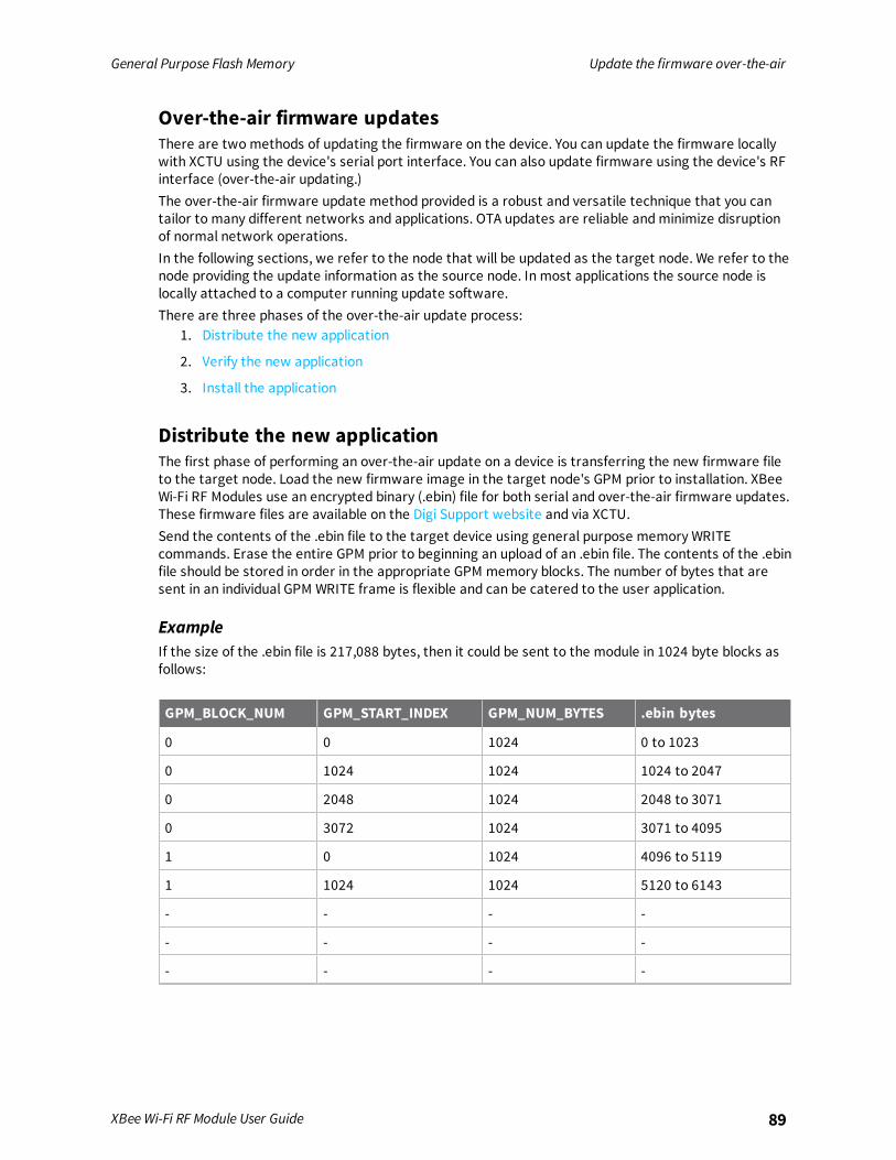
General Purpose Flash Memory Update the firmware over-the-air
XBee Wi-Fi RF Module User Guide 89
Over-the-air firmware updatesThere are two methods of updating the firmware on the device. You can update the firmware locallywith XCTU using the device's serial port interface. You can also update firmware using the device's RFinterface (over-the-air updating.)The over-the-air firmware update method provided is a robust and versatile technique that you cantailor to many different networks and applications. OTA updates are reliable andminimize disruptionof normal network operations.In the following sections, we refer to the node that will be updated as the target node. We refer to thenode providing the update information as the source node. In most applications the source node islocally attached to a computer running update software.There are three phases of the over-the-air update process:
1. Distribute the new application
2. Verify the new application
3. Install the application
Distribute the new applicationThe first phase of performing an over-the-air update on a device is transferring the new firmware fileto the target node. Load the new firmware image in the target node's GPM prior to installation. XBeeWi-Fi RF Modules use an encrypted binary (.ebin) file for both serial and over-the-air firmware updates.These firmware files are available on the Digi Support website and via XCTU.Send the contents of the .ebin file to the target device using general purpose memory WRITEcommands. Erase the entire GPM prior to beginning an upload of an .ebin file. The contents of the .ebinfile should be stored in order in the appropriate GPM memory blocks. The number of bytes that aresent in an individual GPM WRITE frame is flexible and can be catered to the user application.
ExampleIf the size of the .ebin file is 217,088 bytes, then it could be sent to the module in 1024 byte blocks asfollows:
GPM_BLOCK_NUM GPM_START_INDEX GPM_NUM_BYTES .ebin bytes
0 0 1024 0 to 1023
0 1024 1024 1024 to 2047
0 2048 1024 2048 to 3071
0 3072 1024 3071 to 4095
1 0 1024 4096 to 5119
1 1024 1024 5120 to 6143
- - - -
- - - -
- - - -

General Purpose Flash Memory Update the firmware over-the-air
XBee Wi-Fi RF Module User Guide 90
GPM_BLOCK_NUM GPM_START_INDEX GPM_NUM_BYTES .ebin bytes
52 1024 214,016 to 215,039
52 2048 215,040 to 216,063
52 3072 216,064 to 217,087
Verify the new applicationFor an uploaded application to function correctly, every single byte from the .ebin file must be properlytransferred to the GPM. To guarantee that this is the case, GPM VERIFY functions exist to ensure thatall bytes are properly in place. The FIRMWARE_VERIFY function reports whether or not the uploadeddata is valid. The FIRMWARE_VERIFY_AND_INSTALL command reports if the uploaded data is invalid. Ifthe data is valid, it begins installing the application. No installation takes place on invalid data.
Install the applicationWhen the entire .ebin file is uploaded to the GPM of the target node, you can issue a FIRMWARE_VERIFY_AND_INSTALL command. Once the target receives the command it verifies the .ebin fileloaded in the GPM. If it is valid, then the device installs the new firmware. This installation process cantake up to eight seconds. During the installation the device is unresponsive to both serial and RFcommunication. To complete the installation, the target module resets. AT parameter settings whichhave not been written to flash using the WR command will be lost.
Important considerationsThe firmware upgrade process requires that the device resets itself. Because of this reset parameterswhich have not been written to flash are lost after the reset. To avoid this, write all parameters withthe WR command before doing a firmware upgrade.Because explicit API Tx frames can be addressed to a local node (accessible via the SPI or UART) or aremote node (accessible over the RF port) the same process can be used to update firmware on adevice in either case.
Configure the XBee Wi-Fi RF Module using DigiRemote Manager
Use Digi Remote Manager (https://remotemanager.digi.com/) to perform the operations in thissection. Each operation requires that you enable Remote Manager with the DO command and thatyou connect the XBee Wi-Fi RF Module to an access point that has an external Internet connection toallow access to Digi Remote Manager.
Note Digi is consolidating our cloud services, Digi Device Cloud and Digi Remote Manager®, under theRemote Manager name. This phased process does not affect device functionality or the functionalityof the web services and other features. However, customers will find that some user interface andfirmware functionality mention both Device Cloud and Digi Remote Manager.
Use XCTU to enable Remote Manager 92Configure the device 92Output control 93IO command bits 93Send I/O samples to Remote Manager 94View I/O samples in Remote Manager 94Update the firmware 95Send data requests 95Enable messages to the host 95About the device request and frame ID 96Populate and send a Device Request frame (0xB9) 96Transparent mode data 97
XBee Wi-Fi RF Module User Guide 91
Configure the XBee Wi-Fi RF Module using Digi Remote Manager Use XCTU to enable Remote Manager
XBee Wi-Fi RF Module User Guide 92
Use XCTU to enable Remote ManagerTo enable an XBee Wi-Fi RF Module connected to XCTU for Remote Manager:
1. Select the device in the Radio Modules list.
2. In the Working area of XCTU, type 1 in the DO (Device Options) command field; this enablesRemote Manager for the device.
3. Click the Write button.
Configure the deviceIf your XBee devices are connected to Remote Manager, you can query and configure the XBee Wi-FiRF Module through Remote Manager. To do this:
1. Log in to Remote Manager.
2. Click the Device Management tab.
3. Click the XBee Networks tab.
4. Double click the device you want to configure.
5. Click Configuration. A list of AT command types displays.
6. Click the category of AT commands that you want to modify, Network Settings for example.
7. Change the settings of the appropriate AT command(s).
8. Click the Refresh button to query the current configuration.
9. Click the Save button to save the current configuration changes. If the changes are valid,Remote Manager writes them to non-volatile memory and applies them.
10. If you want to apply these changes later, click the drop-down arrow on the Save button andselect Schedule.
11. The Save Device Properties dialog allows you to schedule changes to connected devices to beeither:
a. Immediate (default)
b. One-Time: Schedule a one-time reboot at a specified date and time.
c. Recurring: Set a recurring reboot schedule, with start and end dates and times, aswell as frequency.
d. Schedule Offline: Queue device reboot to occur the next time this device connectsto Remote Manager.
12. Click the Export button to export the device’s settings; the Export Properties dialog appears.
13. Choose the Export all option (default) or Export all except unique network and deviceidentity properties.
14. Click OK. A message appears, asking whether you want to open or save the downloaded file.

Configure the XBee Wi-Fi RF Module using Digi Remote Manager Output control
XBee Wi-Fi RF Module User Guide 93
Output controlYou can find Executable Commands in Device Management. Select an XBee Wi-Fi RF Module and clickSystem Information. The executable commands are the IO (Set Output Pins) andOM (Output Mask)commands.
1. Log in to Remote Manager.
2. Click the Device Management tab.
3. Click the XBee Networks tab.
4. Double click the device you want to configure.
5. Click System Information. A list of AT command types displays.
6. Click Executable commands.
7. In the (IO) Set output pins field, configure the pins that you want to set the output to thedesired level. None of the pins are configured for output by default. The parameter given to theIO command is a bit map that specifies which IO lines are set to which levels; see IO commandbits for details on the bits.
8. In the (OM) Set mask for IO command field set the bits you want to control.The OM command is an output mask that enables (1) or disables (0) the corresponding bit inthe IO command. To control the output level of a pin with an IO command, you set thecorresponding bit in the OM command and you configure the corresponding pin (for exampleDIO2 for bit 2) as an output low (4) or output high (5).
9. Send the IO command to set the output to the desired level. (0 sets it low and 1 sets it high.)
Each pin also has an associated timer to be used in conjunction with the IO command. The timerdetermines how long the IO command remains effective for each IO pin that is set to a level differentthan its configured value. If the timer is set to a default value of 0, then the IO command remains ineffect until it is overridden by another IO command or you reset the module. Otherwise, the timerspecifies the number of tenth second (100 ms) units that the device stays at the selected level beforereverting to its configured level. The maximum value allowed is 6000 (0x1770), which allows for tenminutes.The AT commands for these timers are T0 through T9 for pins DIO0 through DIO9 andQ0 through Q9for pins DIO10 through DIO19. To modify these commands, click Configuration > Input and OutputSettings and use the choice menu to modify the time.
IO command bitsThe IO command sets the level of output pins to high or low. The parameter you give to the IOcommand is a bit map that specifies which I/O pins are set to which levels. The following table showsthe bits and the corresponding pin.No pins are configured for output by default.
Bit I/O pin
0 DIO0
1 DIO1
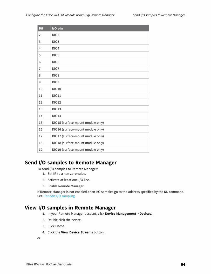
Configure the XBee Wi-Fi RF Module using Digi Remote Manager Send I/O samples to Remote Manager
XBee Wi-Fi RF Module User Guide 94
Bit I/O pin
2 DIO2
3 DIO3
4 DIO4
5 DIO5
6 DIO6
7 DIO7
8 DIO8
9 DIO9
10 DIO10
11 DIO11
12 DIO12
13 DIO13
14 DIO14
15 DIO15 (surface-mount module only)
16 DIO16 (surface-mount module only)
17 DIO17 (surface-mount module only)
18 DIO18 (surface-mount module only)
19 DIO19 (surface-mount module only)
Send I/O samples to Remote ManagerTo send I/O samples to Remote Manager:
1. Set IR to a non-zero value.
2. Activate at least one I/O line.
3. Enable Remote Manager.
If Remote Manager is not enabled, then I/O samples go to the address specified by the DL command.See Periodic I/O sampling.
View I/O samples in Remote Manager1. In your Remote Manager account, click Device Management > Devices.
2. Double click the device.
3. Click Home.
4. Click the View Device Streams button.or

Configure the XBee Wi-Fi RF Module using Digi Remote Manager Update the firmware
XBee Wi-Fi RF Module User Guide 95
1. Click Data Services > Data Streams.
2. In the Stream column, click the MAC address of the module/serial/0.
The data streams are organized by the serial number of the sending device and then by the signal linebeing monitored.
Update the firmwareThe XBee Wi-Fi RF Module supports Remote Manager firmware updates. To perform a firmwareupdate, use the following steps.
1. Download the updated firmware file for your device from the manufacturer's site.
2. In your Remote Manager account, click Device Management > Devices.
3. Select the first device you want to update.
4. To select multiple devices (must be of the same type), press the Control key and selectadditional devices.
5. Click More in the Devices toolbar and select Update Firmware from the Update category ofthe More menu. The Update Firmware dialog appears.
6. Click Browse to select the appropriate firmware file for the device. The file must have a .ebinextension, which indicates an encrypted binary file. This same file is normally zipped up withthe .mxi file of each firmware release.
7. Click Update Firmware. The updated devices will automatically reboot when the updates arecomplete.
Send data requestsThe Send Data request allows the host to use the XBee Wi-Fi RF Module to send a file to RemoteManager. To send a request, a host connected to the serial port of the device sends a Send DataRequest - 0x28 API frame.
Enable messages to the hostIf you have a host application connected to the serial port of the XBee Wi-Fi RF Module, you can enableRemote Manager to send a message to the host, as the following sequence shows.
1. In Remote Manager, send the Device Request frame - 0xB9 to the host.
2. If the Device Request frame (0xB9) ID is non-zero, then after the Device Request frame (0xB9)goes out the serial port, the host has up to five seconds to send back a Device Response frame(0x2A).
3. If the host does not send a Device Response - 0x2A, the XBee Wi-Fi RF Module sends a timeoutresponse to Remote Manager.
4. After the host sends a Device Response frame (0x2A), the XBee Wi-Fi RF Module sends a DeviceResponse Status frame - 0xBA to the host.

Configure the XBee Wi-Fi RF Module using Digi Remote Manager About the device request and frame ID
XBee Wi-Fi RF Module User Guide 96
About the device request and frame IDThe firmware uses two identifiers in these three frames to correlate the messages:
1. The device request ID identifies the device request
2. The frame ID identifies the device response
The host reads the Device Request frame (0xB9) ID when it is received on the serial port. If the devicerequest ID is non-zero, it generates a device response containing that same device request ID. Amismatch causes an error. In addition to the Device Request frame (0xB9) ID, the Device Responseframe (0x2A) that the host generates contains a frame ID. A frame ID of 0 instructs the XBee devicenot to send a Device Response Status frame (0xBA). A non-zero frame ID is a request for a DeviceResponse Status frame (0xBA), which includes the designated frame ID. Therefore, a Device Requestframe (0xB9) contains a device request ID, a Device Response frame (0x2A) contains a device requestID and a frame ID, and a Device Response Status frame (0xBA) contains only a frame ID.
Populate and send a Device Request frame (0xB9)1. In Remote Manager, click Documentation > API Explorer.
2. Click Examples > SCI > Data Service > Send request. A sample XML file that you can modifyappears as seen in the following code sample:
<sci_request version="1.0"><data_service>
<targets><device id="00000000-00000000-00000000-00000000"/>
</targets><requests>
<device_request target_name="myTarget">my payload string</device_request>
</requests></data_service>
</sci_request>
3. Under <targets> type the MAC address of the XBee Wi-Fi RF Module in this format:
00000000-00000000-010203FF-FF040506where 01 to 06 are the first through sixth bytes of the MAC address, respectively, and 00 andFF are literally 00 and FF. In Remote Manager, you can find the device MAC address in thisformat in the device’s Home field.

Configure the XBee Wi-Fi RF Module using Digi Remote Manager Transparent mode data
XBee Wi-Fi RF Module User Guide 97
4. Under <requests>, you can type a target name as desired, but any target name beginning withXBee (case insensitive) is reserved for use on the XBee device itself and will not be sent out theserial port.
5. Type the string that will be output in the device request. Both the target name and the devicerequest string depend on your application and the XBee device passes these strings on,unmodified.
6. In the HTTP Method field, select the POST option button.
7. Click Send. The device response appears in the Web Services Responses pane.
Transparent mode dataThe XBee Wi-Fi RF Module also supports Remote Manager transmissions and receptions inTransparent mode. Transparent data is sent to Remote Manager using the Send Data interface andTransparent data is received from Remote Manager using the Device Request interface. Some partsof those interfaces are lost due to not using the API interface.
Send data to Remote ManagerThe device can send serial data to Remote Manager as files or as binary data points. To make thisselection, use bit 4 of DO command. If you set DO bit 4, then the serially-connected host sendsTransparent data to Remote Manager as binary data points. Otherwise, it sends the data as a file.Files are static and permanent. Data streams are dynamic and you can graph them to understandchanges.
AT command settings to put serial data in Remote ManagerAPI Enable command:
0: Transparent Mode1: API Mode without escapes2: API Mode with escapes
EQ (Device Cloud FQDN) command:The URL for Remote Manager must be my.devicecloud.com or devicecloud.digi.com
DO command command:

Configure the XBee Wi-Fi RF Module using Digi Remote Manager Transparent mode data
XBee Wi-Fi RF Module User Guide 98
Bits 0-7: Encoded in Hex.0: Enable Remote Manager (1), Disable (0).1: Soft AP when ID = None. This has nothing to do with Remote Manager.2: Send Transparent Data to Remote Manager (1), send to DL (0).3: Send IO both to Remote Manager and DL (1), Remote Manager only (0).4: Send Transparent data as a data stream (1), file data (0) – must have bit 2.5: If bit 4 is 0, replace file (1), append to file (0).
Hence, the following values:00: Do not use Remote Manager at all.05: Send Transparent data to Remote Manager as a file which is appended (00000101).
/ws/FileData/~/00000000-00000000-00409DFF-FFxxxxxx/serial/025: Send transparent data to Remote Manager as a file which is overwritten (00100101)
/ws/FileData/~/00000000-00000000-00409DFF-FFxxxxxx/serial/015: Send transparent data to Remote Manager as a data point – encoded in BINARY
/ws/v1/streams/inventory/00000000-00000000-00409DFF-FF5DB54F/serial/0/ws/DataPoint/00000000-00000000-00409DFF-FF5DB54F/serial/0/ws/DataStream/00000000-00000000-00409DFF-FF5DB54F/serial/0
01: Connect to Remote Manager, but send Transparent data to the address and port of DL/DE usingthe protocol in IP.
This is convenient if you want to use the TCP or UDP method for posting at datapoint.
Send filesThe file name that is written on Remote Manager is named serial/0. The file type is text/plain. DOcommand bit 5 selects whether to append to an existing file or to replace it. If replacing an existing fileand the size of the data being sent exceeds the maximum frame size allowed (1400 bytes), then thatframe isbroken up and only the last part shows up in the file because the last part will replace ratherthan append to the first part.
Send binary data pointsTo send binary data points to Remote Manager in Transparent mode: set DO command to 0x15 or0x17, which means:
n Set DO to bit 4.
n Set DO bit 0 to enable Remote Manager.
n Set DO bit 2 so Transparent data goes to Remote Manager.
To view the files:1. Double click the device.
2. Click Home.
3. Click the View Device Streams button.or
1. Click Data Services > Data Streams.
2. In the Stream column, click the MAC address of the module/serial/0.

Configure the XBee Wi-Fi RF Module using Digi Remote Manager Transparent mode data
XBee Wi-Fi RF Module User Guide 99
Receive data from Remote ManagerTransparent data is received from Remote Manager using the Device Request interface if the device isoperating in Transparent mode (AP = 0) and Remote Manager is enabled with DO bit 0. Only the rawdata is seen on the serial interface and the target string to which Remote Manager sent the data isnot available.You must use API mode to see the target string. In Transparent mode, Remote Manager should notrequest a response because none is given.
Operate in API mode
API mode overview 101Use the AP command to set the operation mode 101API frame format 101API serial exchanges 105Frame descriptions 107
XBee Wi-Fi RF Module User Guide 100
Operate in API mode API mode overview
XBee Wi-Fi RF Module User Guide 101
API mode overviewAs an alternative to Transparent operating mode, you can use API operating mode. API mode providesa structured interface where data is communicated through the serial interface in organized packetsand in a determined order. This enables you to establish complex communication between deviceswithout having to define your own protocol. The API specifies how commands, command responsesand device status messages are sent and received from the device using the serial interface or theSPI interface.We may add new frame types to future versions of firmware, so build the ability to filter out additionalAPI frames with unknown frame types into your software interface.
Use the AP command to set the operation modeUse API Enable to specify the operation mode:
AP commandsetting Description
AP = 0 Transparent operating mode, UART serial line replacement with API modesdisabled. This is the default option.
AP = 1 API operation.
AP = 2 API operation with escaped characters (only possible on UART).
The API data frame structure differs depending on what mode you choose.
API frame formatAn API frame consists of the following:
n Start delimeter
n Length
n Frame data
n Checksum
API operation (AP parameter = 1)This is the recommended API mode for most applications. The following table shows the data framestructure when you enable this mode:
Frame fields Byte Description
Start delimiter 1 0x7E
Length 2 - 3 Most Significant Byte, Least Significant Byte
Frame data 4 - number (n) API-specific structure
Checksum n + 1 1 byte

Operate in API mode API frame format
XBee Wi-Fi RF Module User Guide 102
Any data received prior to the start delimiter is silently discarded. If the frame is not received correctlyor if the checksum fails, the XBee replies with a radio status frame indicating the nature of the failure.
API operation with escaped characters (AP parameter = 2)Setting API to 2 allows escaped control characters in the API frame. Due to its increased complexity,we only recommend this API mode in specific circumstances. API 2 may help improve reliability if theserial interface to the device is unstable or malformed frames are frequently being generated.When operating in API 2, if an unescaped 0x7E byte is observed, it is treated as the start of a new APIframe and all data received prior to this delimiter is silently discarded. For more information on usingthis API mode, see the Escaped Characters and API Mode 2 in the Digi Knowledge base.API escaped operating mode works similarly to API mode. The only difference is that when working inAPI escapedmode, the software must escape any payload bytes that match API frame specific data,such as the start-of-frame byte (0x7E). The following table shows the structure of an API frame withescaped characters:
Frame fields Byte Description
Start delimiter 1 0x7E
Length 2 - 3 Most Significant Byte, Least Significant Byte Characters escaped if needed
Frame data 4 - n API-specific structure
Checksum n + 1 1 byte
Escaped characters in API framesIf operating in API mode with escaped characters (AP parameter = 2), when sending or receiving aserial data frame, specific data values must be escaped (flagged) so they do not interfere with thedata frame sequencing. To escape an interfering data byte, insert 0x7D and follow it with the byte tobe escaped (XORed with 0x20).The following data bytes need to be escaped:
n 0x7E: start delimiter
n 0x7D: escape character
n 0x11: XON
n 0x13: XOFF
To escape a character:1. Insert 0x7D (escape character).
2. Append it with the byte you want to escape, XORed with 0x20.
In API mode with escaped characters, the length field does not include any escape characters in theframe and the firmware calculates the checksum with non-escaped data.
Example: escape an API frameTo express the following API non-escaped frame in API operating mode with escaped characters:
Start delimiter Length Frame typeFrame Data
ChecksumData
7E 00 0F 17 01 00 13 A2 00 40 AD 14 2E FF FE 02 4E 49 6D
You must escape the 0x13 byte:

Operate in API mode API frame format
XBee Wi-Fi RF Module User Guide 103
1. Insert a 0x7D.
2. XOR byte 0x13 with 0x20: 13 ⊕ 20 = 33
The following figure shows the resulting frame. Note that the length and checksum are the same asthe non-escaped frame.
Start delimiter Length Frame typeFrame Data
ChecksumData
7E 00 0F 17 01 00 7D 33 A2 00 40 AD 14 2E FF FE 02 4E 49 6D
The length field has a two-byte value that specifies the number of bytes in the frame data field. It doesnot include the checksum field.
Start delimiter fieldThis field indicates the beginning of a frame. It is always 0x7E. This allows the device to easily detect anew incoming frame.
Length fieldThe length field is a two-byte value that specifies the number of bytes contained in the frame datafield. It does not include the checksum field.
Frame dataThis field contains the information that a device receives or will transmit. The structure of frame datadepends on the purpose of the API frame:
Length
Frame data
Data
1 2 3 4 5 6 7 8 9 ... n n+1
0x7E MSB LSB Data
n Frame type is the API frame type identifier. It determines the type of API frame and indicateshow the Data field organizes the information.
n Data contains the data itself. This information and its order depend on the what type of framethat the Frame type field defines.
Multi-byte values are sent big-endian.
Calculate and verify checksumsTo calculate the checksum of an API frame:
1. Add all bytes of the packet, except the start delimiter 0x7E and the length (the second andthird bytes).
2. Keep only the lowest 8 bits from the result.
3. Subtract this quantity from 0xFF.
To verify the checksum of an API frame:1. Add all bytes including the checksum; do not include the delimiter and length.
2. If the checksum is correct, the last two digits on the far right of the sum equal 0xFF.
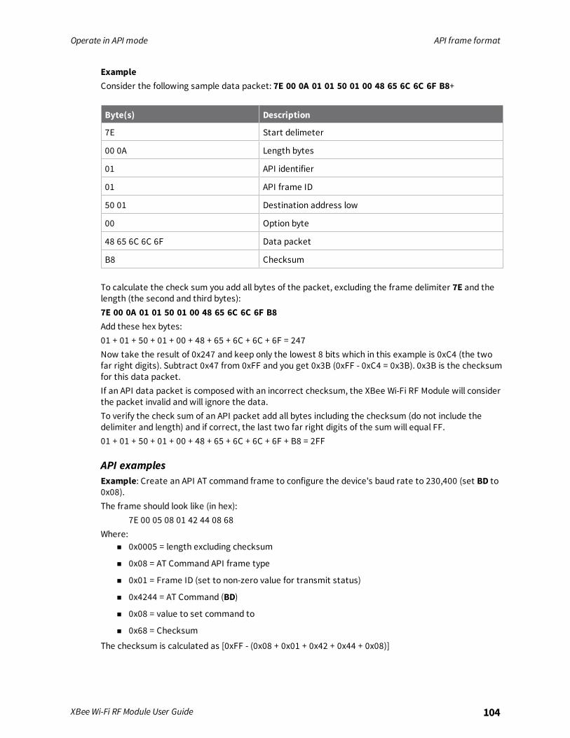
Operate in API mode API frame format
XBee Wi-Fi RF Module User Guide 104
ExampleConsider the following sample data packet: 7E 00 0A 01 01 50 01 00 48 65 6C 6C 6F B8+
Byte(s) Description
7E Start delimeter
00 0A Length bytes
01 API identifier
01 API frame ID
50 01 Destination address low
00 Option byte
48 65 6C 6C 6F Data packet
B8 Checksum
To calculate the check sum you add all bytes of the packet, excluding the frame delimiter 7E and thelength (the second and third bytes):7E 00 0A 01 01 50 01 00 48 65 6C 6C 6F B8Add these hex bytes:01 + 01 + 50 + 01 + 00 + 48 + 65 + 6C + 6C + 6F = 247Now take the result of 0x247 and keep only the lowest 8 bits which in this example is 0xC4 (the twofar right digits). Subtract 0x47 from 0xFF and you get 0x3B (0xFF - 0xC4 = 0x3B). 0x3B is the checksumfor this data packet.If an API data packet is composed with an incorrect checksum, the XBee Wi-Fi RF Module will considerthe packet invalid and will ignore the data.To verify the check sum of an API packet add all bytes including the checksum (do not include thedelimiter and length) and if correct, the last two far right digits of the sum will equal FF.01 + 01 + 50 + 01 + 00 + 48 + 65 + 6C + 6C + 6F + B8 = 2FF
API examplesExample: Create an API AT command frame to configure the device's baud rate to 230,400 (set BD to0x08).The frame should look like (in hex):
7E 00 05 08 01 42 44 08 68Where:
n 0x0005 = length excluding checksum
n 0x08 = AT Command API frame type
n 0x01 = Frame ID (set to non-zero value for transmit status)
n 0x4244 = AT Command (BD)
n 0x08 = value to set command to
n 0x68 = Checksum
The checksum is calculated as [0xFF - (0x08 + 0x01 + 0x42 + 0x44 + 0x08)]

Operate in API mode API serial exchanges
XBee Wi-Fi RF Module User Guide 105
Example: Send a remote command to a device with the IP address 192.168.0.103 (C0 A8 00 67) to setDIO1/AD1 as a digital input (D1=3) and apply changes to force the IO update. The API remotecommand frame should look like (in hex):
7E 00 0E 07 01 00 00 00 00 C0 A8 01 64 02 44 31 03 B0Where:
n 0x000E = length (14 bytes excluding checksum)
n 0x07 = Remote Command API frame type
n 0x01 = Frame ID
n 0x00000000 C0A80067 = Remote address (pad first 4 bytes with 00)
n 0x02 = Apply Changes (Remote Command Options)
n 0x4431 = AT command (D1)
n 0xB0 = Checksum
API serial exchangesYou can use the Frame ID field to assign an identifier to each outgoing API frame. This Frame ID, ifnon-zero, can correlate between the outgoing frames and the associated responses.
AT command framesThe following image shows the API frame exchange that takes place at the UART or SPI interfacewhen sending an AT command request to read or set an XBee parameter. To disable the response, setthe frame ID to 0 in the request.
Transmit and receive RF dataThe following image shows the API exchanges that take place at the serial interface when sending RFdata to another device. The transmit status frame is always sent at the end of a data transmissionunless the frame ID is set to 0 in the TX request. If the packet cannot be delivered to the destination,the transmit status frame indicates the cause of failure. The received data frame type (standard 0x90,or explicit 0x91) is set by the AP command.

Operate in API mode API serial exchanges
XBee Wi-Fi RF Module User Guide 106
Remote AT commandsThe following image shows the API frame exchanges that take place at the serial interface whensending a remote AT command. A remote command response frame is not sent out the serialinterface if the remote device does not receive the remote command.
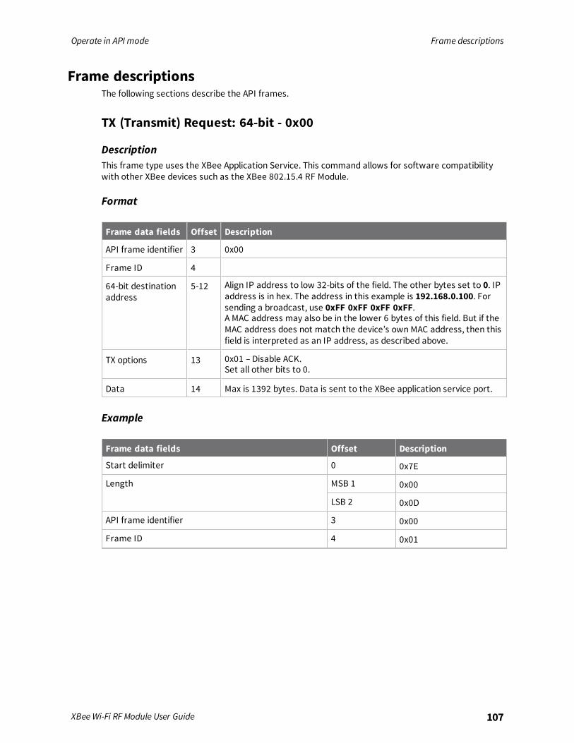
Operate in API mode Frame descriptions
XBee Wi-Fi RF Module User Guide 107
Frame descriptionsThe following sections describe the API frames.
TX (Transmit) Request: 64-bit - 0x00
DescriptionThis frame type uses the XBee Application Service. This command allows for software compatibilitywith other XBee devices such as the XBee 802.15.4 RF Module.
Format
Frame data fields Offset Description
API frame identifier 3 0x00
Frame ID 4
64-bit destinationaddress
5-12 Align IP address to low 32-bits of the field. The other bytes set to 0. IPaddress is in hex. The address in this example is 192.168.0.100. Forsending a broadcast, use 0xFF 0xFF 0xFF 0xFF.A MAC address may also be in the lower 6 bytes of this field. But if theMAC address does not match the device’s own MAC address, then thisfield is interpreted as an IP address, as described above.
TX options 13 0x01 – Disable ACK.Set all other bits to 0.
Data 14 Max is 1392 bytes. Data is sent to the XBee application service port.
Example
Frame data fields Offset Description
Start delimiter 0 0x7E
Length MSB 1 0x00
LSB 2 0x0D
API frame identifier 3 0x00
Frame ID 4 0x01
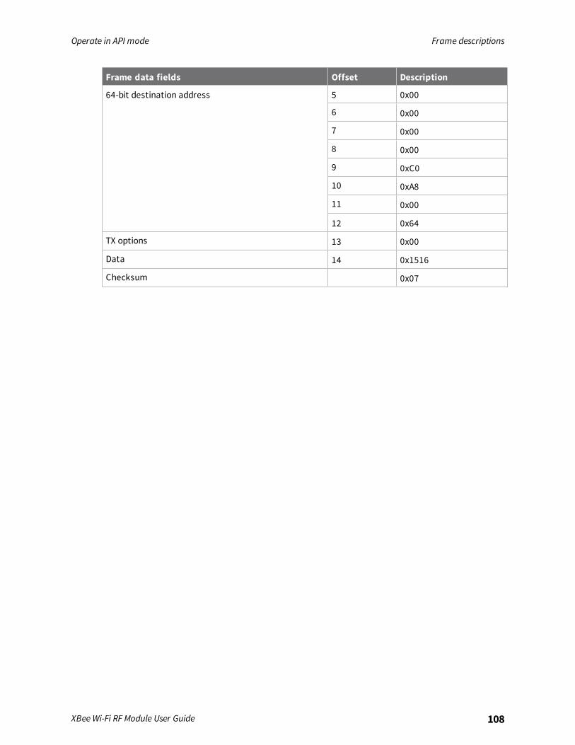
Operate in API mode Frame descriptions
XBee Wi-Fi RF Module User Guide 108
Frame data fields Offset Description
64-bit destination address 5 0x00
6 0x00
7 0x00
8 0x00
9 0xC0
10 0xA8
11 0x00
12 0x64
TX options 13 0x00
Data 14 0x1516
Checksum 0x07

Operate in API mode Frame descriptions
XBee Wi-Fi RF Module User Guide 109
Remote AT Command Request - 0x07
DescriptionUsed to query or set module parameters on a remote module. For parameter changes on the remotemodule to take effect, changes must be applied, either by setting the apply changes options bit, or bysending an AC command to the remote.
Format
Frame datafields Offset Description
API frameidentifier
3
Frame ID 4
64-bit destinationaddress
5 Align IP address to low 32-bits of the field. Set the other bytes to 0. TheIP address is in hex.
A MAC address may also be in the lower 6 bytes of this field. But if theMAC address doesnot match the device’s own MAC address, then thisfield is interpreted as an IP address, as described above.
6
7
8
9
10
11
12
Commandoptions
13 0x02 – Apply changes on the remote. If not set, then the AC commandmust be sent or the last remote command sent must set this option.
AT command MSB 14 Command name: two ASCII characters that identify the AT command.
LSB 15
Parameter value - If present, indicates the requested parameter value to set the givenregister. If no characters are present, the register is queried.
ExampleSend a remote command to query the DL register on a remote device. In this example, the IP addressof the remote is 192.168.0.100.
Frame data fields Offset Description
Start delimiter 0 0x7E

Operate in API mode Frame descriptions
XBee Wi-Fi RF Module User Guide 110
Frame data fields Offset Description
Length MSB 1 0x00
LSB 2 0x0D
API frame identifier 3 0x07
Frame ID 4 0x01
64-bit destination address 5 0x00
6 0x00
7 0x00
8 0x00
9 0xC0
10 0xA8
11 0x00
12 0x64
Command options 13 0x02
AT command MSB 14 0x44 (D)
LSB 15 0x4C (L)
Parameter value -- --
Checksum 16 0x99

Operate in API mode Frame descriptions
XBee Wi-Fi RF Module User Guide 111
AT Command Frame - 0x08
DescriptionUse this frame to query or set device parameters on the local device. This API command applieschanges after running the command. You can query parameter values by sending the 0x08 ATCommand frame with no parameter value field (the two-byte AT command is immediately followed bythe frame checksum).
FormatThe following table provides the contents of the frame.
Framedatafields Offset Description
Frametype
3 0x08
Frame ID 4
ATcommand
5-6 Command name: two ASCII characters that identify the AT command.
Parametervalue
7-n If present, indicates the requested parameter value to set the given register.If no characters are present, it queries the register.
ExampleThe following example illustrates an AT Command frame when you modify the device's NI parametervalue.
Frame data fields Offset Example
Start delimiter 0 0x7E
Length MSB 1 0x00
LSB 2 0x05
Frame type 3 0x08
Frame ID 4 0x01
AT command 5 0x4E (N)
6 0x49 (I)
Parameter value 7 -
Checksum 8 0x5E
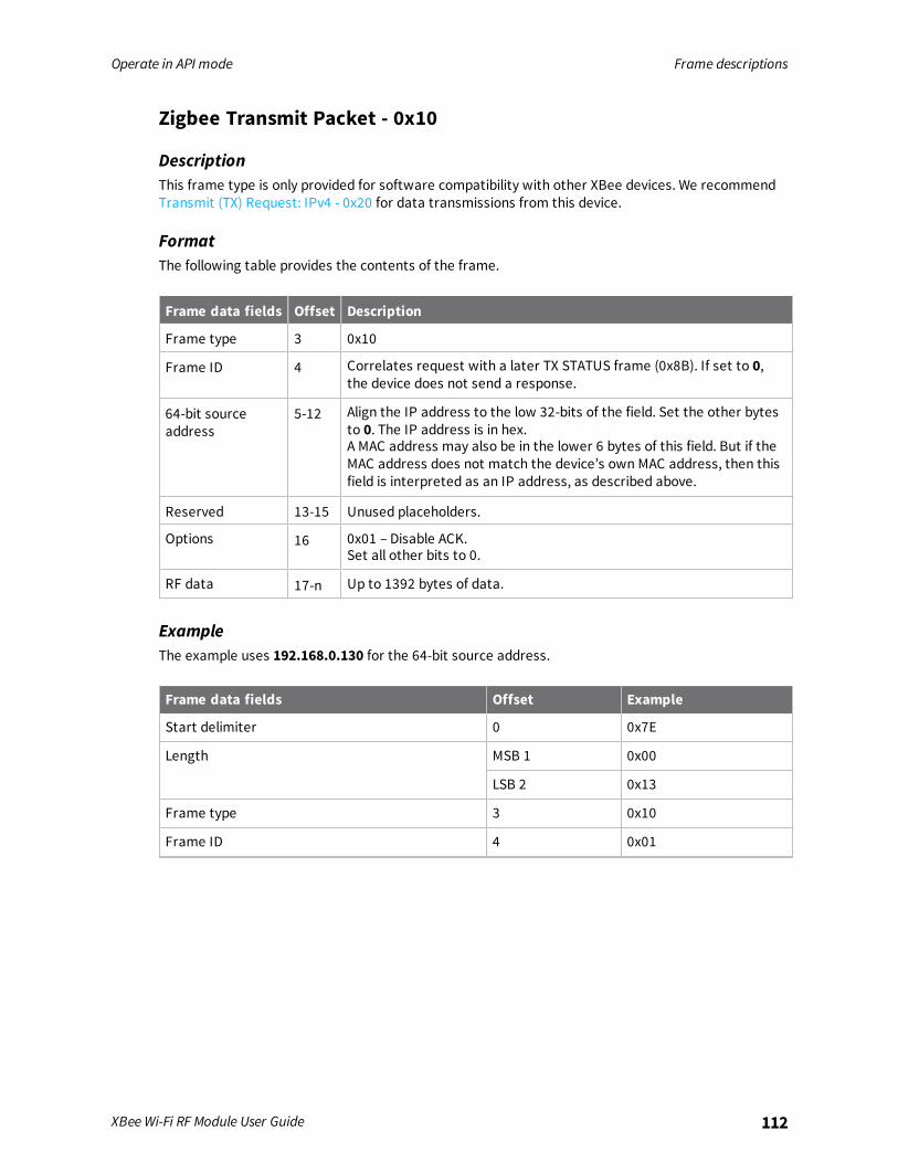
Operate in API mode Frame descriptions
XBee Wi-Fi RF Module User Guide 112
Zigbee Transmit Packet - 0x10
DescriptionThis frame type is only provided for software compatibility with other XBee devices. We recommendTransmit (TX) Request: IPv4 - 0x20 for data transmissions from this device.
FormatThe following table provides the contents of the frame.
Frame data fields Offset Description
Frame type 3 0x10
Frame ID 4 Correlates request with a later TX STATUS frame (0x8B). If set to 0,the device does not send a response.
64-bit sourceaddress
5-12 Align the IP address to the low 32-bits of the field. Set the other bytesto 0. The IP address is in hex.A MAC address may also be in the lower 6 bytes of this field. But if theMAC address does not match the device’s own MAC address, then thisfield is interpreted as an IP address, as described above.
Reserved 13-15 Unused placeholders.
Options 16 0x01 – Disable ACK.Set all other bits to 0.
RF data 17-n Up to 1392 bytes of data.
ExampleThe example uses 192.168.0.130 for the 64-bit source address.
Frame data fields Offset Example
Start delimiter 0 0x7E
Length MSB 1 0x00
LSB 2 0x13
Frame type 3 0x10
Frame ID 4 0x01
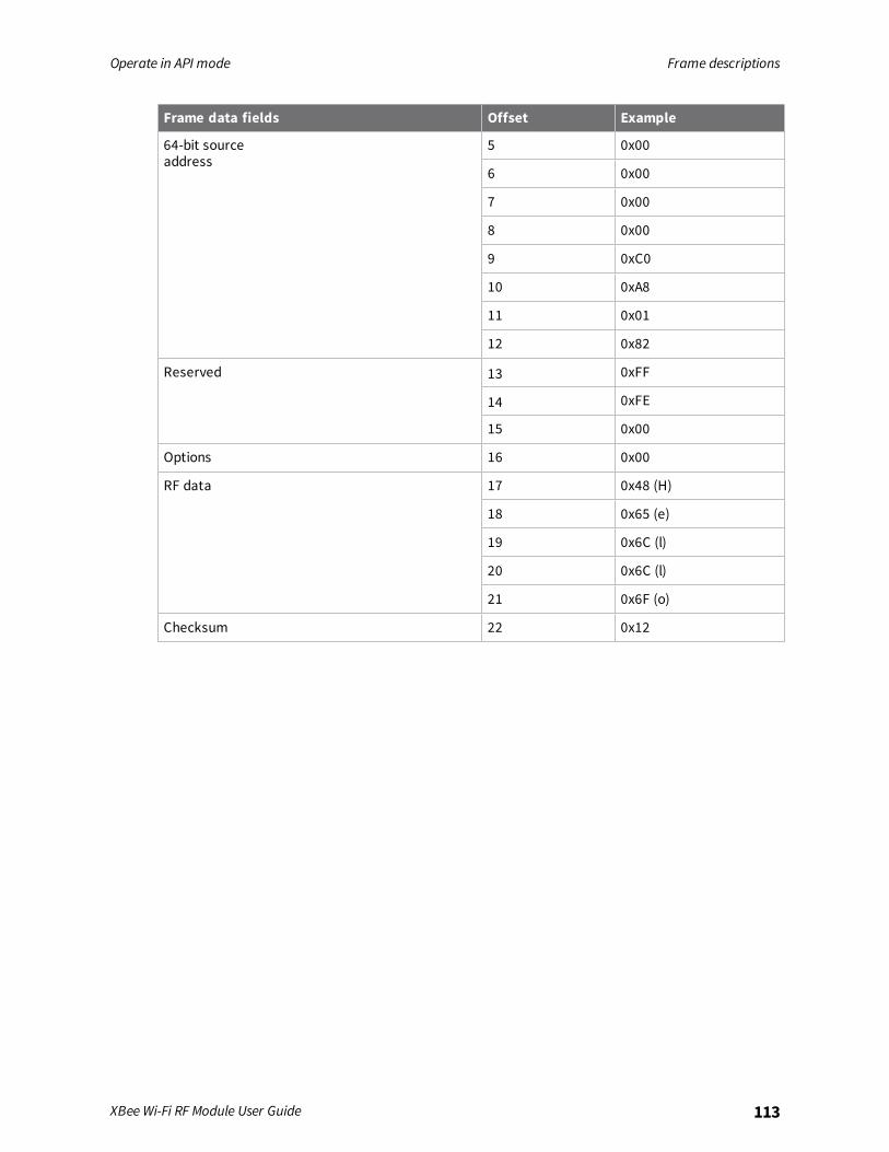
Operate in API mode Frame descriptions
XBee Wi-Fi RF Module User Guide 113
Frame data fields Offset Example
64-bit sourceaddress
5 0x00
6 0x00
7 0x00
8 0x00
9 0xC0
10 0xA8
11 0x01
12 0x82
Reserved 13 0xFF
14 0xFE
15 0x00
Options 16 0x00
RF data 17 0x48 (H)
18 0x65 (e)
19 0x6C (l)
20 0x6C (l)
21 0x6F (o)
Checksum 22 0x12
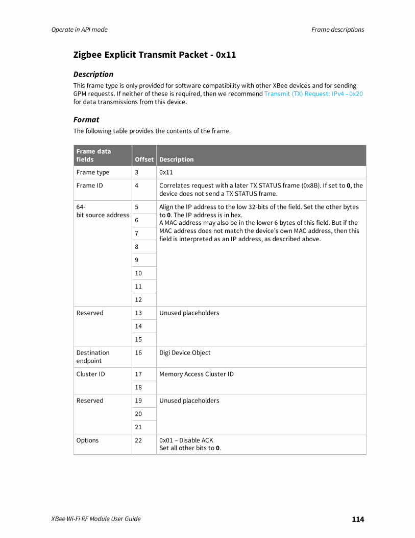
Operate in API mode Frame descriptions
XBee Wi-Fi RF Module User Guide 114
Zigbee Explicit Transmit Packet - 0x11
DescriptionThis frame type is only provided for software compatibility with other XBee devices and for sendingGPM requests. If neither of these is required, then we recommend Transmit (TX) Request: IPv4 - 0x20for data transmissions from this device.
FormatThe following table provides the contents of the frame.
Frame datafields Offset Description
Frame type 3 0x11
Frame ID 4 Correlates request with a later TX STATUS frame (0x8B). If set to 0, thedevice does not send a TX STATUS frame.
64-bit source address
5 Align the IP address to the low 32-bits of the field. Set the other bytesto 0. The IP address is in hex.A MAC address may also be in the lower 6 bytes of this field. But if theMAC address does not match the device’s own MAC address, then thisfield is interpreted as an IP address, as described above.
6
7
8
9
10
11
12
Reserved 13 Unused placeholders
14
15
Destinationendpoint
16 Digi Device Object
Cluster ID 17 Memory Access Cluster ID
18
Reserved 19 Unused placeholders
20
21
Options 22 0x01 – Disable ACKSet all other bits to 0.
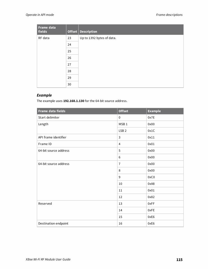
Operate in API mode Frame descriptions
XBee Wi-Fi RF Module User Guide 115
Frame datafields Offset Description
RF data 23 Up to 1392 bytes of data.
24
25
26
27
28
29
30
ExampleThe example uses 192.168.1.130 for the 64-bit source address.
Frame data fields Offset Example
Start delimiter 0 0x7E
Length MSB 1 0x00
LSB 2 0x1C
API frame identifier 3 0x11
Frame ID 4 0x01
64-bit source address 5 0x00
6 0x00
64-bit source address 7 0x00
8 0x00
9 0xC0
10 0xA8
11 0x01
12 0x82
Reserved 13 0xFF
14 0xFE
15 0xE6
Destination endpoint 16 0xE6

Operate in API mode Frame descriptions
XBee Wi-Fi RF Module User Guide 116
Frame data fields Offset Example
Cluster ID 17 0x00
18 0x23
Reserved 19 0xC1
20 0x05
21 0x00
Options 22 0x00
RF data 23 0x00
24 0x00
25 0x00
26 0x00
27 0x00
28 0x00
29 0x00
30 0x00
Checksum 31 0x50

Operate in API mode Frame descriptions
XBee Wi-Fi RF Module User Guide 117
Zigbee Remote AT Command - 0x17
DescriptionThis frame type is only provided for software compatibility with other XBee devices. We recommendRemote AT Command Request - 0x07 for sending remote commands from this device.
FormatThe following table provides the contents of the frame.
Frame data fields Offset Description
Frame type 3 0x17
Frame ID 4
64-bit source address 5 Align the IP address to the low 32-bits of the field. Set the otherbytes to 0. The IP address is in hex.
6
7
8
9
10
11
12
Reserved 13 Unused placeholders
14
Command options 15 0x02 – Apply changes on remote.If not set, then you must send the AC command or the last remotecommand sent must set this option.
AT command 16 Two ASCII characters representing the command name (DL in theexample below).
17
Parameter value 18 Sets DL to 192.168.1.140 in the example below.The parameter value field does not exist on a query.
19
20
21
ExampleThe example uses 192.168.1.130 for the 64-bit source address.
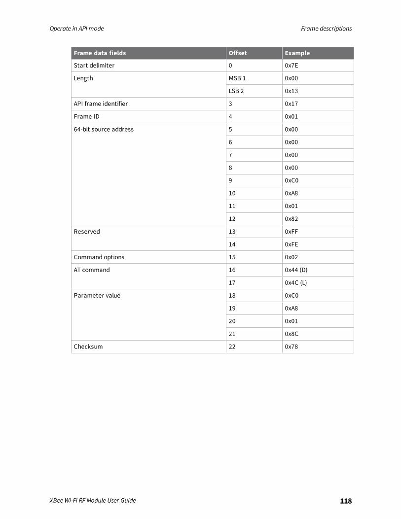
Operate in API mode Frame descriptions
XBee Wi-Fi RF Module User Guide 118
Frame data fields Offset Example
Start delimiter 0 0x7E
Length MSB 1 0x00
LSB 2 0x13
API frame identifier 3 0x17
Frame ID 4 0x01
64-bit source address 5 0x00
6 0x00
7 0x00
8 0x00
9 0xC0
10 0xA8
11 0x01
12 0x82
Reserved 13 0xFF
14 0xFE
Command options 15 0x02
AT command 16 0x44 (D)
17 0x4C (L)
Parameter value 18 0xC0
19 0xA8
20 0x01
21 0x8C
Checksum 22 0x78
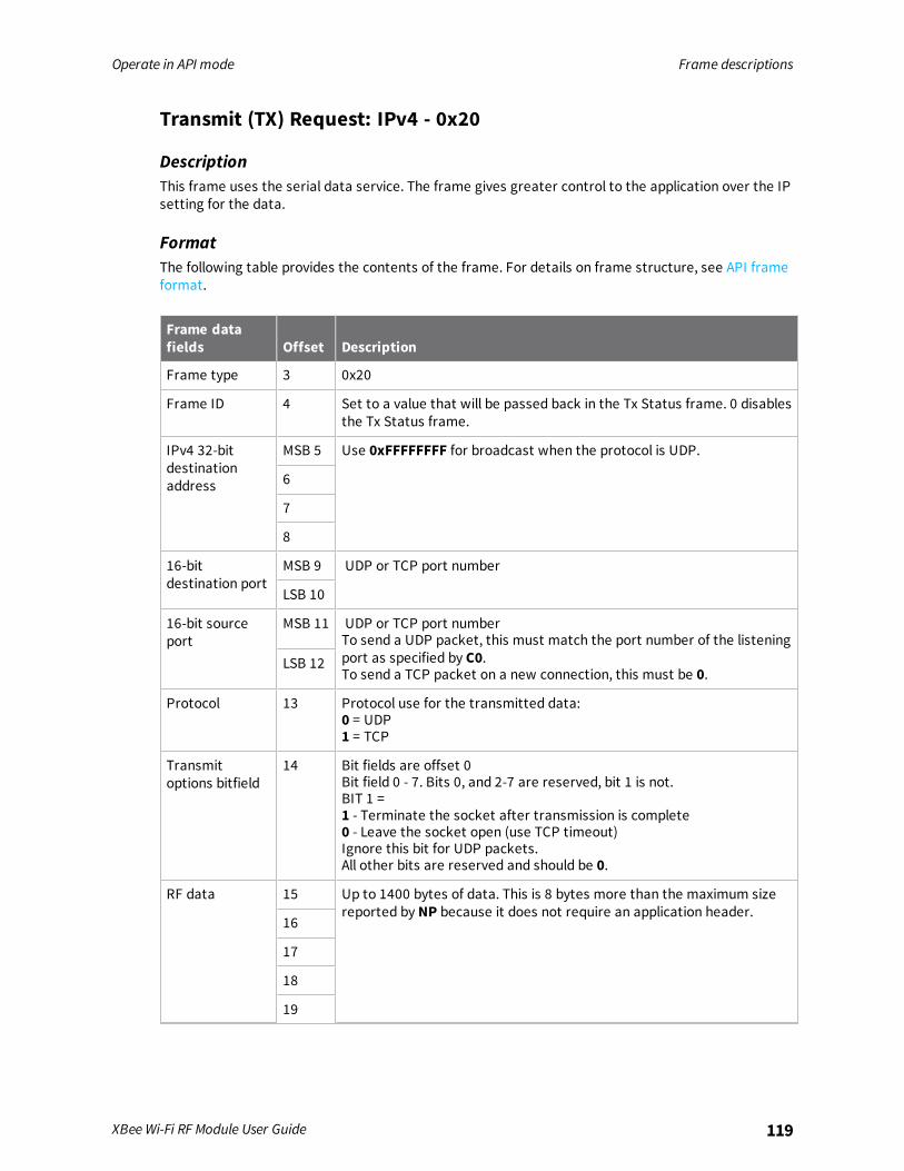
Operate in API mode Frame descriptions
XBee Wi-Fi RF Module User Guide 119
Transmit (TX) Request: IPv4 - 0x20
DescriptionThis frame uses the serial data service. The frame gives greater control to the application over the IPsetting for the data.
FormatThe following table provides the contents of the frame. For details on frame structure, see API frameformat.
Frame datafields Offset Description
Frame type 3 0x20
Frame ID 4 Set to a value that will be passed back in the Tx Status frame. 0 disablesthe Tx Status frame.
IPv4 32-bitdestinationaddress
MSB 5 Use 0xFFFFFFFF for broadcast when the protocol is UDP.
6
7
8
16-bitdestination port
MSB 9 UDP or TCP port number
LSB 10
16-bit sourceport
MSB 11 UDP or TCP port numberTo send a UDP packet, this must match the port number of the listeningport as specified by C0.To send a TCP packet on a new connection, this must be 0.
LSB 12
Protocol 13 Protocol use for the transmitted data:0 = UDP1 = TCP
Transmitoptions bitfield
14 Bit fields are offset 0Bit field 0 - 7. Bits 0, and 2-7 are reserved, bit 1 is not.BIT 1 =1 - Terminate the socket after transmission is complete0 - Leave the socket open (use TCP timeout)Ignore this bit for UDP packets.All other bits are reserved and should be 0.
RF data 15 Up to 1400 bytes of data. This is 8 bytes more than the maximum sizereported by NP because it does not require an application header.
16
17
18
19
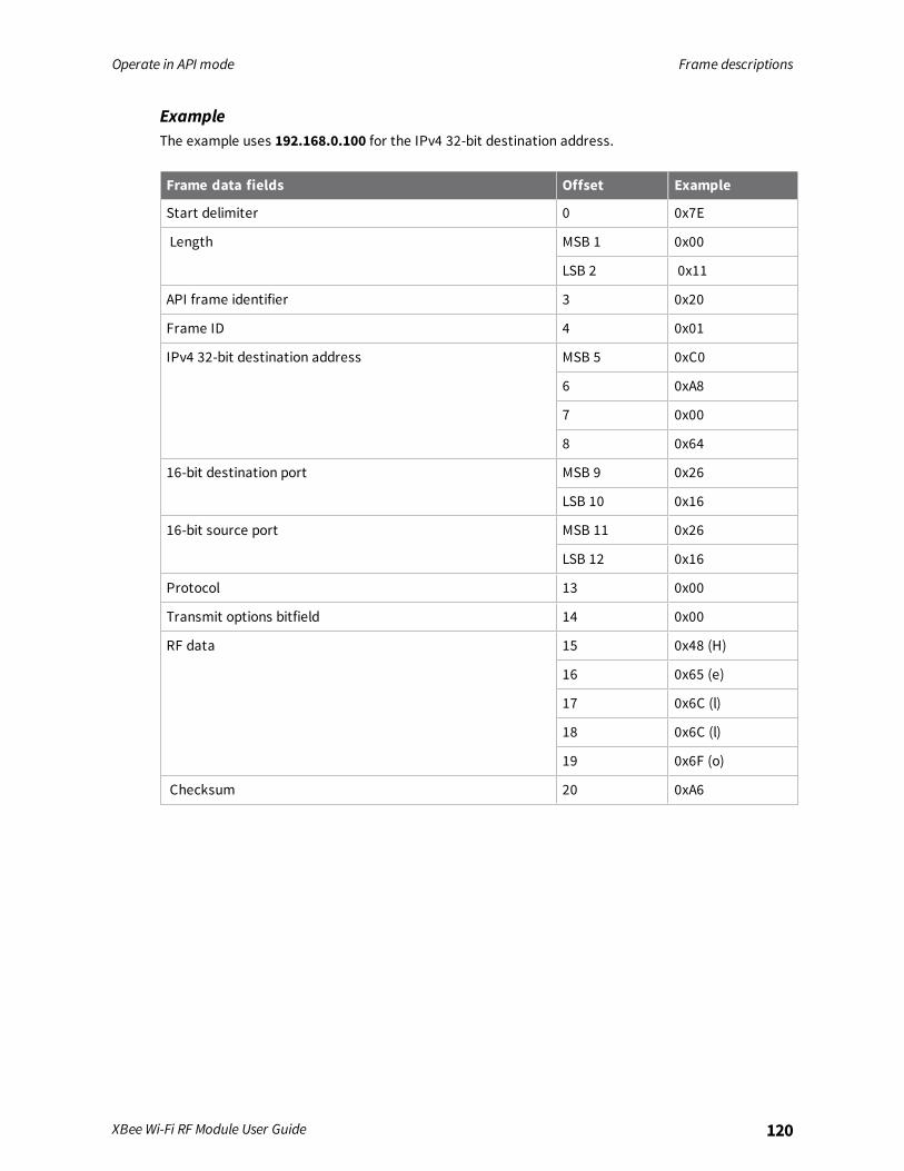
Operate in API mode Frame descriptions
XBee Wi-Fi RF Module User Guide 120
ExampleThe example uses 192.168.0.100 for the IPv4 32-bit destination address.
Frame data fields Offset Example
Start delimiter 0 0x7E
Length MSB 1 0x00
LSB 2 0x11
API frame identifier 3 0x20
Frame ID 4 0x01
IPv4 32-bit destination address MSB 5 0xC0
6 0xA8
7 0x00
8 0x64
16-bit destination port MSB 9 0x26
LSB 10 0x16
16-bit source port MSB 11 0x26
LSB 12 0x16
Protocol 13 0x00
Transmit options bitfield 14 0x00
RF data 15 0x48 (H)
16 0x65 (e)
17 0x6C (l)
18 0x6C (l)
19 0x6F (o)
Checksum 20 0xA6
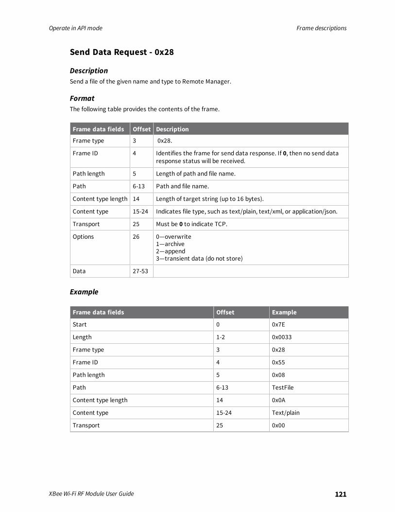
Operate in API mode Frame descriptions
XBee Wi-Fi RF Module User Guide 121
Send Data Request - 0x28
DescriptionSend a file of the given name and type to Remote Manager.
FormatThe following table provides the contents of the frame.
Frame data fields Offset Description
Frame type 3 0x28.
Frame ID 4 Identifies the frame for send data response. If 0, then no send dataresponse status will be received.
Path length 5 Length of path and file name.
Path 6-13 Path and file name.
Content type length 14 Length of target string (up to 16 bytes).
Content type 15-24 Indicates file type, such as text/plain, text/xml, or application/json.
Transport 25 Must be 0 to indicate TCP.
Options 26 0—overwrite1—archive2—append3—transient data (do not store)
Data 27-53
Example
Frame data fields Offset Example
Start 0 0x7E
Length 1-2 0x0033
Frame type 3 0x28
Frame ID 4 0x55
Path length 5 0x08
Path 6-13 TestFile
Content type length 14 0x0A
Content type 15-24 Text/plain
Transport 25 0x00

Operate in API mode Frame descriptions
XBee Wi-Fi RF Module User Guide 122
Frame data fields Offset Example
Options 26 0x00
Data 27-53 abcdefghijklmnopqrstuvwxya
Checksum 54 0x49
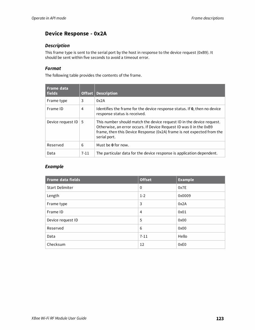
Operate in API mode Frame descriptions
XBee Wi-Fi RF Module User Guide 123
Device Response - 0x2A
DescriptionThis frame type is sent to the serial port by the host in response to the device request (0xB9). Itshould be sent within five seconds to avoid a timeout error.
FormatThe following table provides the contents of the frame.
Frame datafields Offset Description
Frame type 3 0x2A
Frame ID 4 Identifies the frame for the device response status. If 0, then no deviceresponse status is received.
Device request ID 5 This number should match the device request ID in the device request.Otherwise, an error occurs. If Device Request ID was 0 in the 0xB9frame, then this Device Response (0x2A) frame is not expected from theserial port.
Reserved 6 Must be 0 for now.
Data 7-11 The particular data for the device response is application dependent.
Example
Frame data fields Offset Example
Start Delimiter 0 0x7E
Length 1-2 0x0009
Frame type 3 0x2A
Frame ID 4 0x01
Device request ID 5 0x00
Reserved 6 0x00
Data 7-11 Hello
Checksum 12 0xE0
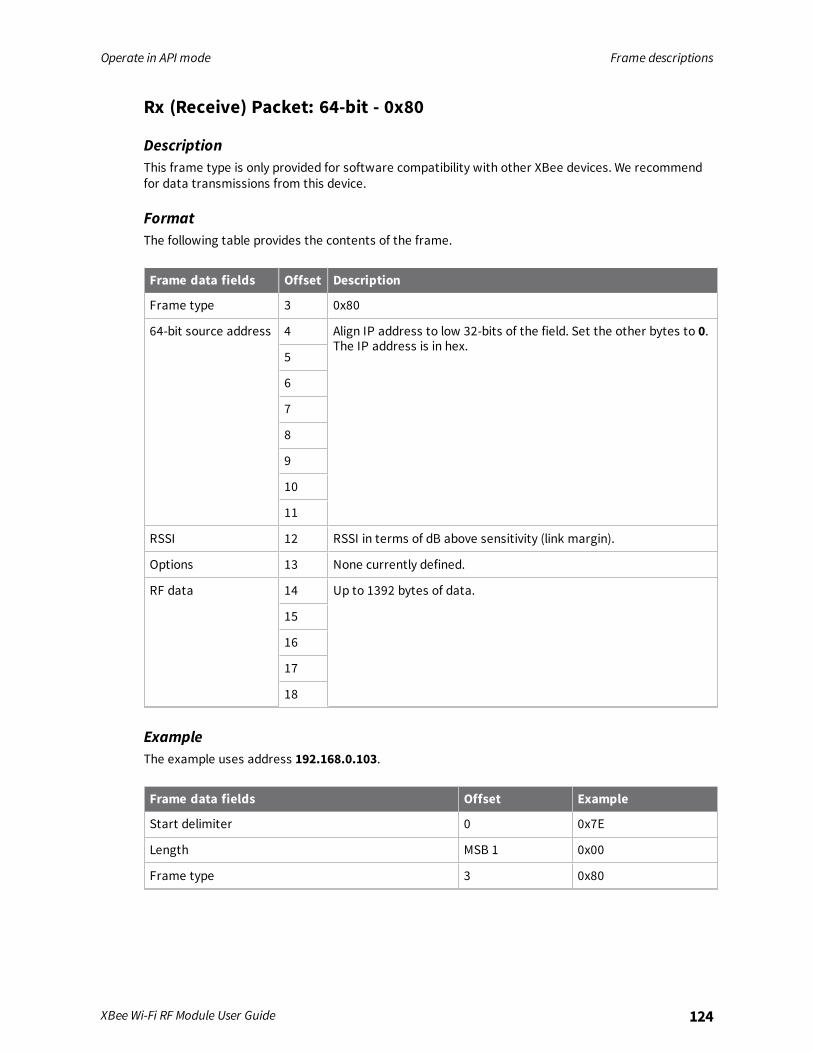
Operate in API mode Frame descriptions
XBee Wi-Fi RF Module User Guide 124
Rx (Receive) Packet: 64-bit - 0x80
DescriptionThis frame type is only provided for software compatibility with other XBee devices. We recommendfor data transmissions from this device.
FormatThe following table provides the contents of the frame.
Frame data fields Offset Description
Frame type 3 0x80
64-bit source address 4 Align IP address to low 32-bits of the field. Set the other bytes to 0.The IP address is in hex.
5
6
7
8
9
10
11
RSSI 12 RSSI in terms of dB above sensitivity (link margin).
Options 13 None currently defined.
RF data 14 Up to 1392 bytes of data.
15
16
17
18
ExampleThe example uses address 192.168.0.103.
Frame data fields Offset Example
Start delimiter 0 0x7E
Length MSB 1 0x00
Frame type 3 0x80
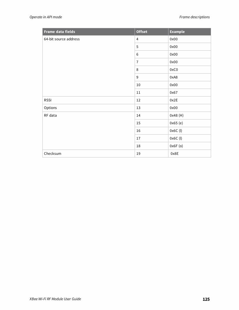
Operate in API mode Frame descriptions
XBee Wi-Fi RF Module User Guide 125
Frame data fields Offset Example
64-bit source address 4 0x00
5 0x00
6 0x00
7 0x00
8 0xC0
9 0xA8
10 0x00
11 0x67
RSSI 12 0x2E
Options 13 0x00
RF data 14 0x48 (H)
15 0x65 (e)
16 0x6C (l)
17 0x6C (l)
18 0x6F (o)
Checksum 19 0x8E
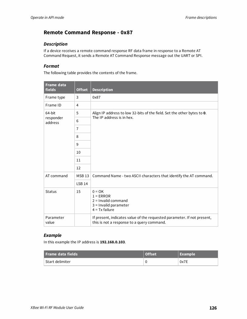
Operate in API mode Frame descriptions
XBee Wi-Fi RF Module User Guide 126
Remote Command Response - 0x87
DescriptionIf a device receives a remote command response RF data frame in response to a Remote ATCommand Request, it sends a Remote AT Command Response message out the UART or SPI.
FormatThe following table provides the contents of the frame.
Frame datafields Offset Description
Frame type 3 0x87
Frame ID 4
64-bitresponderaddress
5 Align IP address to low 32-bits of the field. Set the other bytes to 0.The IP address is in hex.
6
7
8
9
10
11
12
AT command MSB 13 Command Name - two ASCII characters that identify the AT command.
LSB 14
Status 15 0 = OK1 = ERROR2 = Invalid command3 = Invalid parameter4 = Tx failure
Parametervalue
If present, indicates value of the requested parameter. If not present,this is not a response to a query command.
ExampleIn this example the IP address is 192.168.0.103.
Frame data fields Offset Example
Start delimiter 0 0x7E
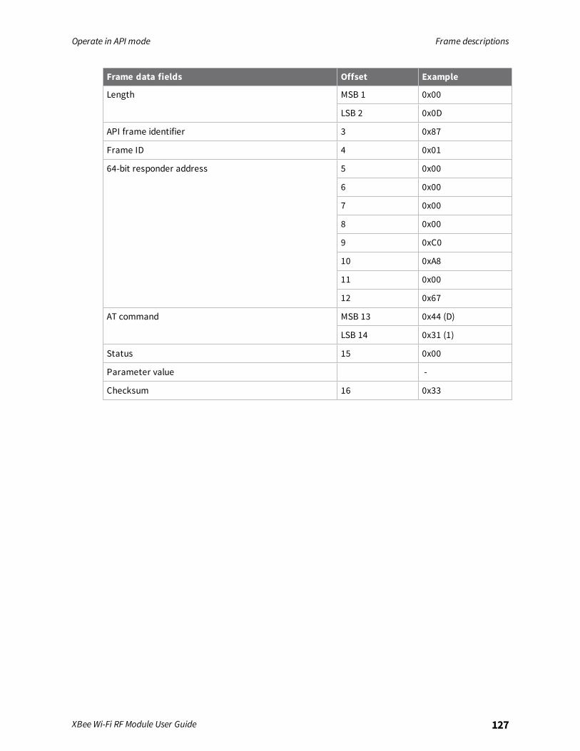
Operate in API mode Frame descriptions
XBee Wi-Fi RF Module User Guide 127
Frame data fields Offset Example
Length MSB 1 0x00
LSB 2 0x0D
API frame identifier 3 0x87
Frame ID 4 0x01
64-bit responder address 5 0x00
6 0x00
7 0x00
8 0x00
9 0xC0
10 0xA8
11 0x00
12 0x67
AT command MSB 13 0x44 (D)
LSB 14 0x31 (1)
Status 15 0x00
Parameter value -
Checksum 16 0x33

Operate in API mode Frame descriptions
XBee Wi-Fi RF Module User Guide 128
AT Command Response frame - 0x88
DescriptionA device sends this frame in response to an AT Commandmessage. Some commands send backmultiple frames (for example, the AS (Active Scan) command).
FormatThe following table provides the contents of the frame.
Frame datafields Offset Description
Frame type 3 0x88
Frame ID 4
AT command 5-6 Command name: two ASCII characters that identify the command.
Commandstatus
0 = OK1 = ERROR2 = Invalid command3 = Invalid parameter
Parametervalue
7 The register data in binary format. If the host sets the register, the devicedoes not return this field.
ExampleIf you change the BD parameter on a local device with a frame ID of 0x01, and the parameter is valid,the user receives the following response.
Frame data fields Offset Example
Start delimiter 0 0x7E
Length MSB 1 0x00
LSB 2 0x05
Frame type 3 0x88
Frame ID 4 0x01
AT command 5 0x42 (B)
6 0x44 (D)
Command status 7 0x00
Command data
Checksum 8 0xF0
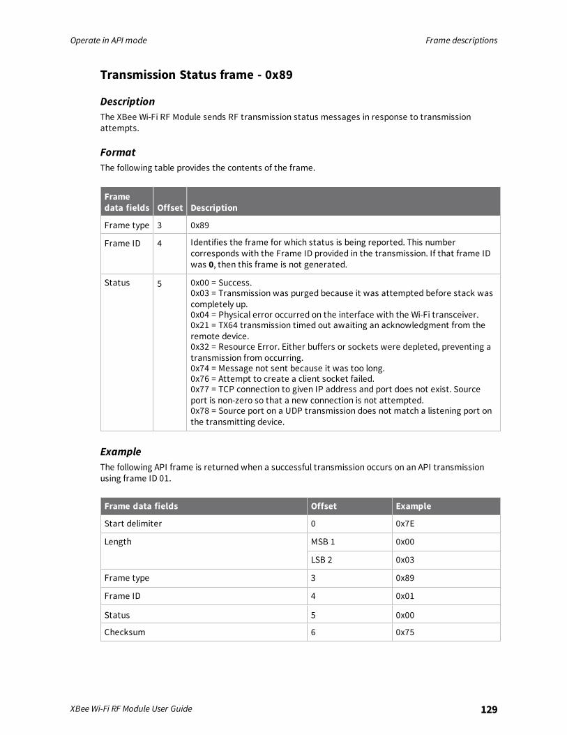
Operate in API mode Frame descriptions
XBee Wi-Fi RF Module User Guide 129
Transmission Status frame - 0x89
DescriptionThe XBee Wi-Fi RF Module sends RF transmission status messages in response to transmissionattempts.
FormatThe following table provides the contents of the frame.
Framedata fields Offset Description
Frame type 3 0x89
Frame ID 4 Identifies the frame for which status is being reported. This numbercorresponds with the Frame ID provided in the transmission. If that frame IDwas 0, then this frame is not generated.
Status 5 0x00 = Success.0x03 = Transmission was purged because it was attempted before stack wascompletely up.0x04 = Physical error occurred on the interface with the Wi-Fi transceiver.0x21 = TX64 transmission timed out awaiting an acknowledgment from theremote device.0x32 = Resource Error. Either buffers or sockets were depleted, preventing atransmission from occurring.0x74 = Message not sent because it was too long.0x76 = Attempt to create a client socket failed.0x77 = TCP connection to given IP address and port does not exist. Sourceport is non-zero so that a new connection is not attempted.0x78 = Source port on a UDP transmission does not match a listening port onthe transmitting device.
ExampleThe following API frame is returned when a successful transmission occurs on an API transmissionusing frame ID 01.
Frame data fields Offset Example
Start delimiter 0 0x7E
Length MSB 1 0x00
LSB 2 0x03
Frame type 3 0x89
Frame ID 4 0x01
Status 5 0x00
Checksum 6 0x75

Operate in API mode Frame descriptions
XBee Wi-Fi RF Module User Guide 130
Modem Status frame - 0x8A
DescriptionDevices send the status messages in this frame in response to specific conditions.
FormatThe following table provides the contents of the frame.
Frame data fields Offset Description
Frame type 3 0x8A
Status 4 0 = Hardware reset or power up1 = Watchdog timer reset2 = Joined3 = No longer joined to access point0x0E = Remote Manager connected0x0F = Remote Manager disconnected
ExampleThe XBee Wi-Fi RF Module returns the following API frame when it is powered on in API mode.
Frame data fields Offset Example
Start delimiter 0 0x7E
Length MSB 1 0x00
LSB 2 LSB 2 0x02
Frame type 3 0x8A
Status 4 0x00
Checksum 5 0x75
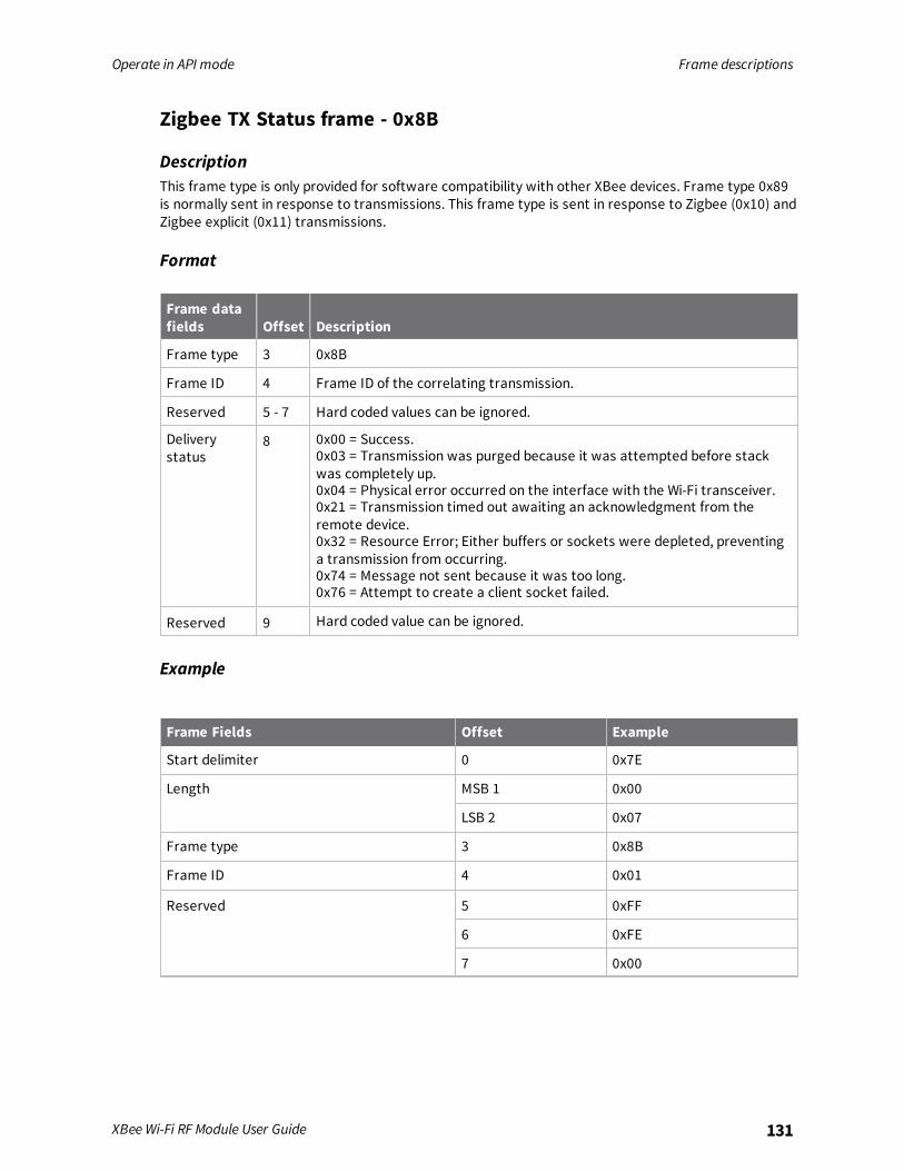
Operate in API mode Frame descriptions
XBee Wi-Fi RF Module User Guide 131
Zigbee TX Status frame - 0x8B
DescriptionThis frame type is only provided for software compatibility with other XBee devices. Frame type 0x89is normally sent in response to transmissions. This frame type is sent in response to Zigbee (0x10) andZigbee explicit (0x11) transmissions.
Format
Frame datafields Offset Description
Frame type 3 0x8B
Frame ID 4 Frame ID of the correlating transmission.
Reserved 5 - 7 Hard coded values can be ignored.
Deliverystatus
8 0x00 = Success.0x03 = Transmission was purged because it was attempted before stackwas completely up.0x04 = Physical error occurred on the interface with the Wi-Fi transceiver.0x21 = Transmission timed out awaiting an acknowledgment from theremote device.0x32 = Resource Error; Either buffers or sockets were depleted, preventinga transmission from occurring.0x74 = Message not sent because it was too long.0x76 = Attempt to create a client socket failed.
Reserved 9 Hard coded value can be ignored.
Example
Frame Fields Offset Example
Start delimiter 0 0x7E
Length MSB 1 0x00
LSB 2 0x07
Frame type 3 0x8B
Frame ID 4 0x01
Reserved 5 0xFF
6 0xFE
7 0x00

Operate in API mode Frame descriptions
XBee Wi-Fi RF Module User Guide 132
Frame Fields Offset Example
Status 8 0x00
Reserved 9 0x00
Checksum 10 0x76

Operate in API mode Frame descriptions
XBee Wi-Fi RF Module User Guide 133
I/O Data Sample RX Indicator frame - 0x8F
DescriptionWhen the XBee Wi-Fi RF Module receives an I/O sample frame from a remote device, it sends thesample out the UART or SPI using this frame type. Only devices running API mode are able to receiveI/O samples.
Format
Frame fields Offset Description
Frame type 3 0x8F
64-bit sourceaddress
4 - 11 Align IP address to low 32-bits of the field. Set the other bytes to 0.The IP address is in hex. The example below uses address192.168.0.103.
RSSI in terms of linkmargin
12
Receive options 13 None currently defined.
Number of samples 14 Number of sample sets included in the payload. Always set to 1.
Digital Channel Mask(see below)
MSB 15 Bitmask field that indicates which digital I/O lines on the remotehave sampling enabled (if any). In the example below, DIO8 isactive.LSB 16
Analog ChannelMask(see below)
17 Bitmask field that indicates which analog I/O lines on the remotehave sampling enabled (if any). The most significant bit signals thatthe Vcc value are included in the frame. In the example below,Analog input 1 and Vcc are active.
Digital Samples (ifincluded)
MSB 18 If the sample set includes any digital I/O lines (Digital Channel Mask> 0), these two bytes contain samples for all enabled digital I/Olines. DIO lines that do not have sampling enabled return 0. The bitsin these 2 bytes map the same as they do in the Digital ChannelsMask field. In the example below, DIO8 has value 0.
LSB 19
Analog Sample MSB 20 If the sample set includes any analog input lines (Analog ChannelMask > 0), each enabled analog input returns a 2-byte valueindicating the A/D measurement of that input. Analog samples areordered sequentially from DIO0/AD0 to DIO3/AD3.
LSB 21
Digital Channel bitmask
N/A N/A N/A CD/DIO12 PWM/DIO11 RSSI/DIO10 N/A N/A
CTS/DIO7 RTS/DIO6 ASSOC/DIO5 DIO4 AD3/DIO3 AD2/DIO2 AD1/DIO1 AD0/DIO0
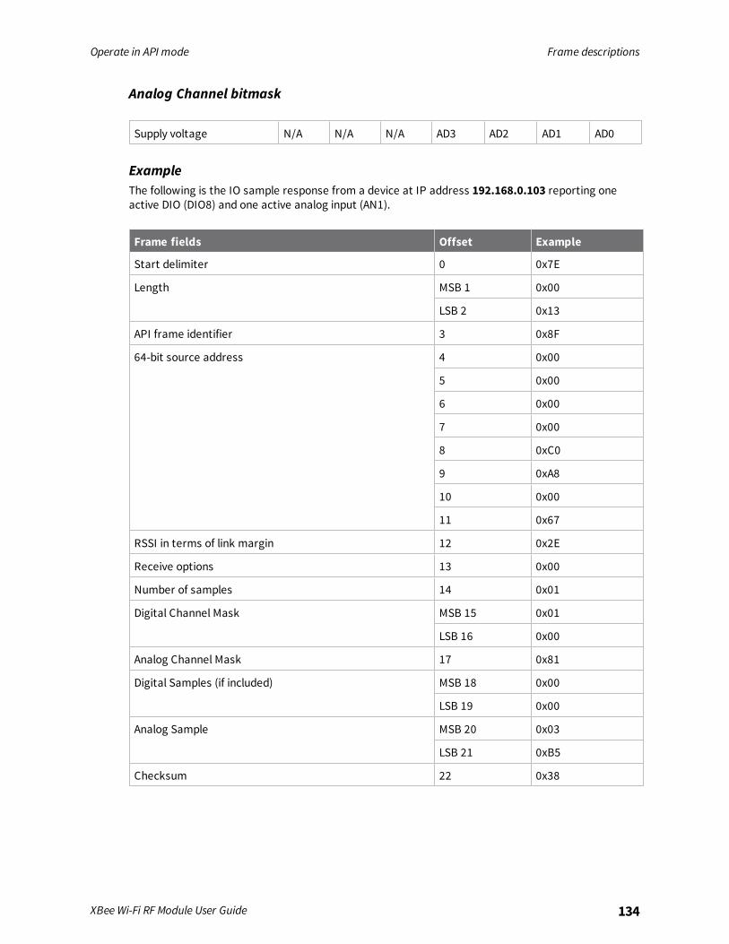
Operate in API mode Frame descriptions
XBee Wi-Fi RF Module User Guide 134
Analog Channel bitmask
Supply voltage N/A N/A N/A AD3 AD2 AD1 AD0
ExampleThe following is the IO sample response from a device at IP address 192.168.0.103 reporting oneactive DIO (DIO8) and one active analog input (AN1).
Frame fields Offset Example
Start delimiter 0 0x7E
Length MSB 1 0x00
LSB 2 0x13
API frame identifier 3 0x8F
64-bit source address 4 0x00
5 0x00
6 0x00
7 0x00
8 0xC0
9 0xA8
10 0x00
11 0x67
RSSI in terms of link margin 12 0x2E
Receive options 13 0x00
Number of samples 14 0x01
Digital Channel Mask MSB 15 0x01
LSB 16 0x00
Analog Channel Mask 17 0x81
Digital Samples (if included) MSB 18 0x00
LSB 19 0x00
Analog Sample MSB 20 0x03
LSB 21 0xB5
Checksum 22 0x38

Operate in API mode Frame descriptions
XBee Wi-Fi RF Module User Guide 135
Zigbee Receive Packet frame 0x90
DescriptionThe XBee Wi-Fi RF Module uses this frame when it receives RF data using the XBee application serviceand AO = 0. It is not generally used, but it allows for software compatibility with other XBee devices ifdesired.
Format
Frame datafields Offset Description
Frame type 3 0x90
64-bit sourceaddress
4-11 Align the IP address to low 32-bits of the field. Set the other bytes to 0.The IP address is in hex.
Reserved 12-13 Unused placeholder.
Options 14 Bit 1: Broadcast packet.
RF data 15-n Up to 1392 bytes of data.
ExampleIn the following example, a device with a 64-bit address of 0x0013A200 40522BAA sends a unicastdata transmission to a remote device with payload RxData. If AO=0 on the receiving device, it sendsthe following frame out its serial interface.
Frame data fields Offset Example
Start delimiter 0 0x7E
Length MSB 1 0x00
LSB 2 0x11
Frame type 3 0x90
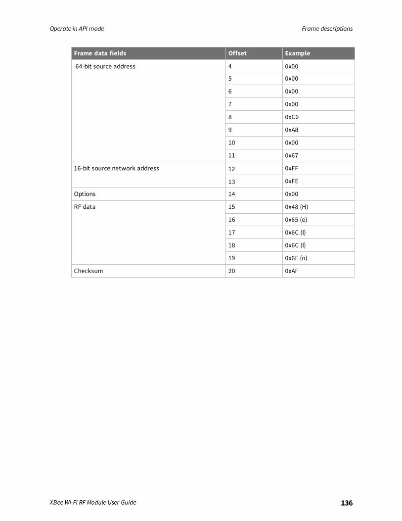
Operate in API mode Frame descriptions
XBee Wi-Fi RF Module User Guide 136
Frame data fields Offset Example
64-bit source address 4 0x00
5 0x00
6 0x00
7 0x00
8 0xC0
9 0xA8
10 0x00
11 0x67
16-bit source network address 12 0xFF
13 0xFE
Options 14 0x00
RF data 15 0x48 (H)
16 0x65 (e)
17 0x6C (l)
18 0x6C (l)
19 0x6F (o)
Checksum 20 0xAF
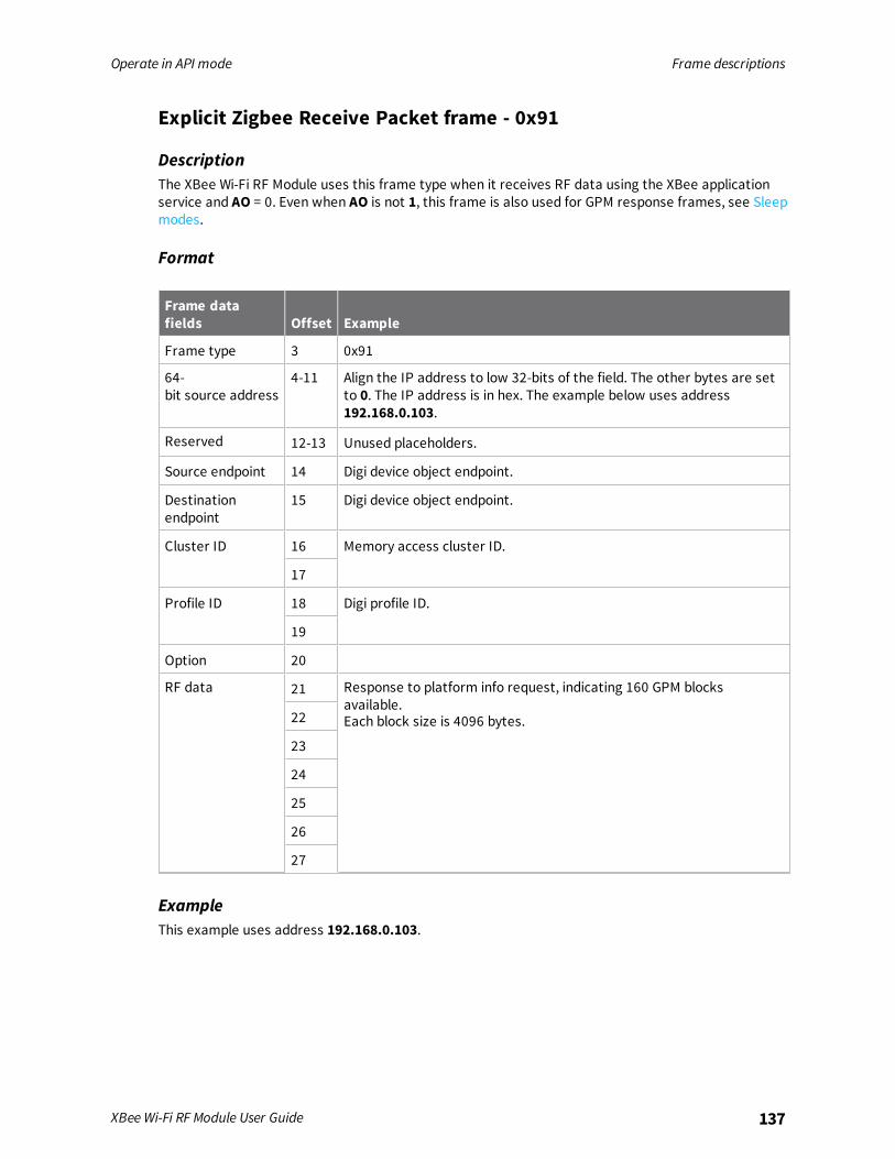
Operate in API mode Frame descriptions
XBee Wi-Fi RF Module User Guide 137
Explicit Zigbee Receive Packet frame - 0x91
DescriptionThe XBee Wi-Fi RF Module uses this frame type when it receives RF data using the XBee applicationservice and AO = 0. Even when AO is not 1, this frame is also used for GPM response frames, see Sleepmodes.
Format
Frame datafields Offset Example
Frame type 3 0x91
64-bit source address
4-11 Align the IP address to low 32-bits of the field. The other bytes are setto 0. The IP address is in hex. The example below uses address192.168.0.103.
Reserved 12-13 Unused placeholders.
Source endpoint 14 Digi device object endpoint.
Destinationendpoint
15 Digi device object endpoint.
Cluster ID 16 Memory access cluster ID.
17
Profile ID 18 Digi profile ID.
19
Option 20
RF data 21 Response to platform info request, indicating 160 GPM blocksavailable.Each block size is 4096 bytes.22
23
24
25
26
27
ExampleThis example uses address 192.168.0.103.
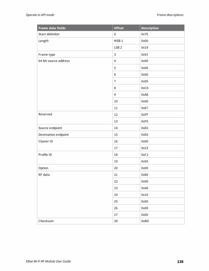
Operate in API mode Frame descriptions
XBee Wi-Fi RF Module User Guide 138
Frame data fields Offset Description
Start delimiter 0 0x7E
Length MSB 1 0x00
LSB 2 0x19
Frame type 3 0x91
64-bit source address 4 0x00
5 0x00
6 0x00
7 0x00
8 0xC0
9 0xA8
10 0x00
11 0x67
Reserved 12 0xFF
13 0xFE
Source endpoint 14 0xE6
Destination endpoint 15 0xE6
Cluster ID 16 0x00
17 0x23
Profile ID 18 0xC1
19 0x05
Option 20 0x00
RF data 21 0x80
22 0x00
23 0xA0
24 0x10
25 0x00
26 0x00
27 0x00
Checksum 28 0xBD

Operate in API mode Frame descriptions
XBee Wi-Fi RF Module User Guide 139
Zigbee Remote AT Command Response frame - 0x97
DescriptionThis frame type is only provided for software compatibility with other XBee devices. It generates aresponse to the Zigbee Remote AT Command - 0x17 frame. Normally, customer use Remote ATCommand Request - 0x07 instead with Remote Command Response - 0x87.
Format
Frame data fields Offset Description
Frame type 3 0x97
Frame ID 4
64-bit source (remote)address
5-12 The address of the remote device returning this response.Align the IP address to the low 32-bits of the field. Set theother bytes to 0.The Value is in hex. In the example below, the IP address is192.168.0.103.
Reserved 13-14 Unused placeholder.
AT command 15-16 The name of the command.
Command status 17 0 = OK1 = ERROR2 = Invalid command3 = Invalid parameter
Command data 18-n If present, indicates the value of the requested parametervalue.If not present, this is not a response to a query command.
ExampleIn the example below, the IP address is 192.168.0.103.
Frame data fields Offset Example
Start delimiter 0 0x7E
Length MSB 1 0x00
LSB 2 0x0F
Frame type 3 0x97
Frame ID 4 0x01
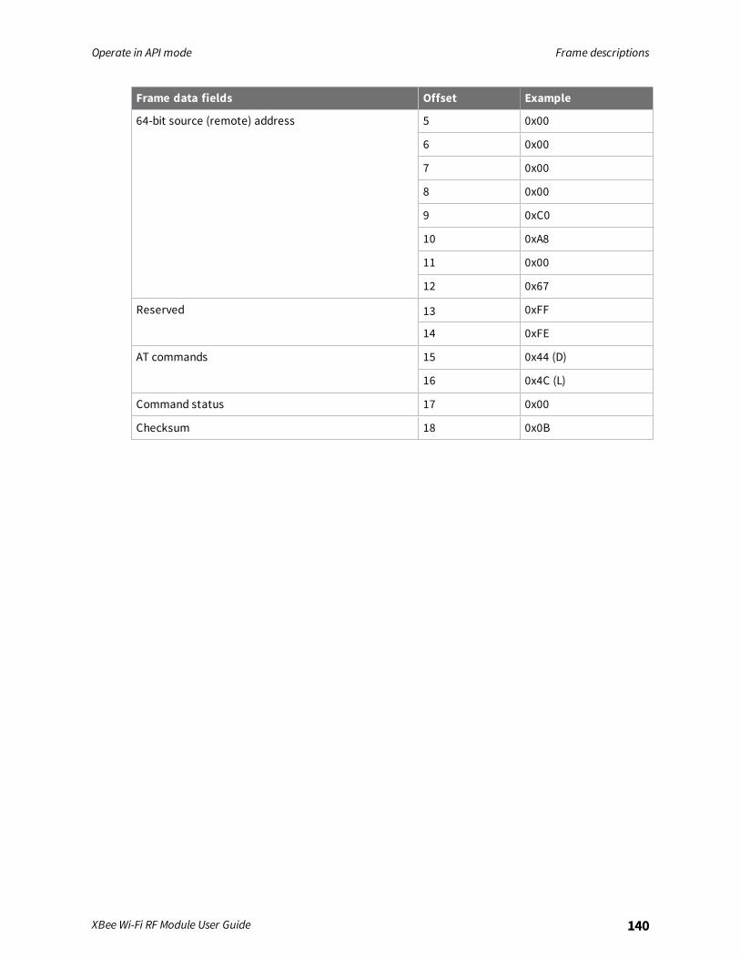
Operate in API mode Frame descriptions
XBee Wi-Fi RF Module User Guide 140
Frame data fields Offset Example
64-bit source (remote) address 5 0x00
6 0x00
7 0x00
8 0x00
9 0xC0
10 0xA8
11 0x00
12 0x67
Reserved 13 0xFF
14 0xFE
AT commands 15 0x44 (D)
16 0x4C (L)
Command status 17 0x00
Checksum 18 0x0B

Operate in API mode Frame descriptions
XBee Wi-Fi RF Module User Guide 141
RX (Receive) Packet: IPv4 - 0xB0
DescriptionThis frame is used by the XBee Wi-Fi RF Module it receives RF data using the Serial Data service on theport defined by C0 (Serial Communication Service Port).
FormatThe following table provides the contents of the frame. For details on frame structure, see API frameformat.
Frame data fields Offset Description
Frame type 3 0xB0
IPv4 32-bit sourceaddress
MSB 4 The address in the example below is for a source address of192.168.0.104.
5
6
7
16-bit destinationport
MSB 8 Same value as the C0 command.
LSB 9
16-bit source port MSB10
LSB11
Protocol MSB12
0 = UDP1 = TCP - Protocol use for the transmitted data
Status 13 Reserved
RF data 14 Up to 1400 bytes of data.This is 8 bytes more than the max size reported by the NP commandbecause no application header is needed.15
16
17
18
ExampleWhen a device in API mode receives an IPv4 transmission, it produces an RX notification (0xB0) andsends it out the UART or SPI port. This example is the response to a UDP transmission to IP address192.168.0.103 with data Hello from the source address 192.168.0.104.

Operate in API mode Frame descriptions
XBee Wi-Fi RF Module User Guide 142
Frame data fields Offset Example
Start delimiter 0 0x7E
Length MSB 1 0x00
Frame type 3 0xB0
IPv4 32-bit source address MSB 4 0xC0
5 0xA8
6 0x00
7 0x68
16-bit destination port MSB 8 0x26
LSB 9 0x16
16-bit source port MSB 10 0x26
LSB 11 0x16
Protocol MSB 12 0x00
Status 13 0x00
RF data 14 0x48 (H)
15 0x65 (e)
16 0x6C (l)
17 0x6C (l)
18 0x6F (o)
Checksum 19 0x13

Operate in API mode Frame descriptions
XBee Wi-Fi RF Module User Guide 143
Send Data Response frame - 0xB8
DescriptionThis frame type is sent out the serial port in response to Send Data Request - 0x28, providing its frameID is non-zero.
FormatThe following table provides the contents of the frame.
Frame data fields Offset Description
Frame type 3 0xB8
Frame ID 4 Identifies the frame ID of the corresponding send data request.
Status 5 0x00 = Success0x01 = Bad request0x02 = Response unavailable0x03 = Remote Manager Error0x40 = Unknown error
Example
Frame data fields Offset Example
Start delimiter 0 0x7E
Length 1-2 0x0003
Frame type 3 0xB8
Frame ID 4 0x55
Status 5 0x00
Checksum 6 0xF2
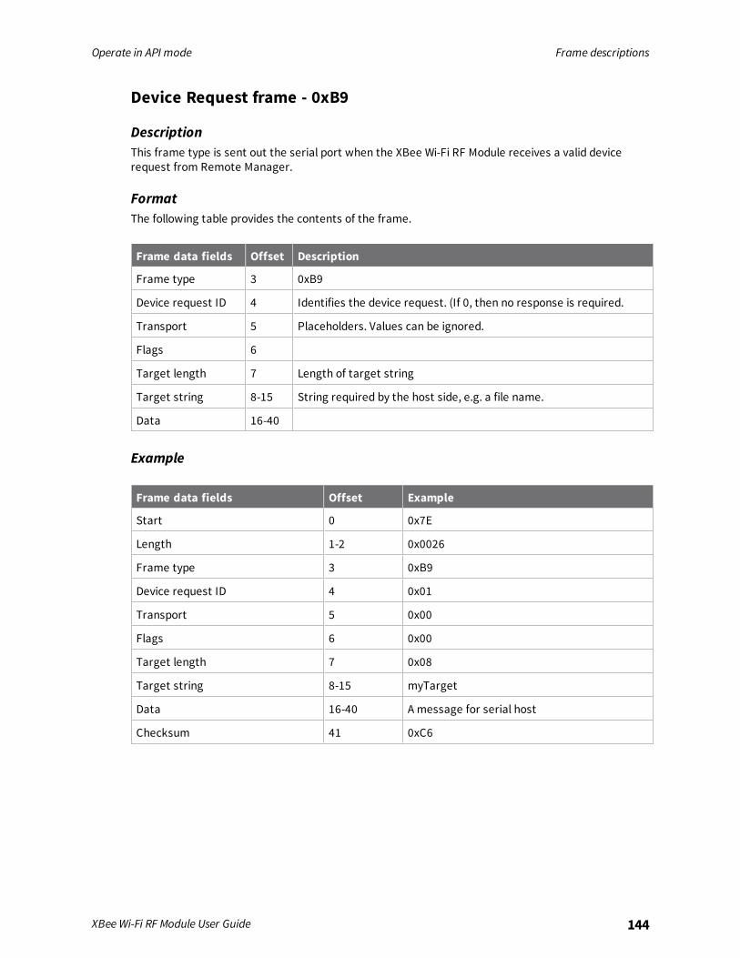
Operate in API mode Frame descriptions
XBee Wi-Fi RF Module User Guide 144
Device Request frame - 0xB9
DescriptionThis frame type is sent out the serial port when the XBee Wi-Fi RF Module receives a valid devicerequest from Remote Manager.
FormatThe following table provides the contents of the frame.
Frame data fields Offset Description
Frame type 3 0xB9
Device request ID 4 Identifies the device request. (If 0, then no response is required.
Transport 5 Placeholders. Values can be ignored.
Flags 6
Target length 7 Length of target string
Target string 8-15 String required by the host side, e.g. a file name.
Data 16-40
Example
Frame data fields Offset Example
Start 0 0x7E
Length 1-2 0x0026
Frame type 3 0xB9
Device request ID 4 0x01
Transport 5 0x00
Flags 6 0x00
Target length 7 0x08
Target string 8-15 myTarget
Data 16-40 A message for serial host
Checksum 41 0xC6
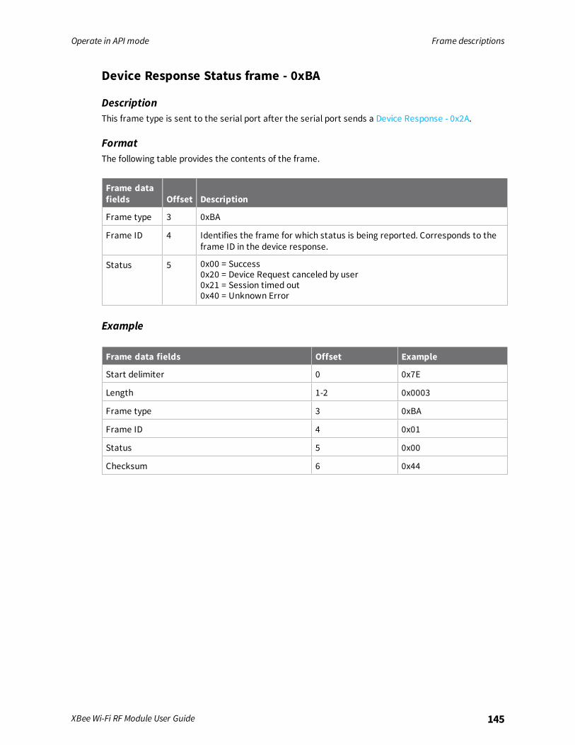
Operate in API mode Frame descriptions
XBee Wi-Fi RF Module User Guide 145
Device Response Status frame - 0xBA
DescriptionThis frame type is sent to the serial port after the serial port sends a Device Response - 0x2A.
FormatThe following table provides the contents of the frame.
Frame datafields Offset Description
Frame type 3 0xBA
Frame ID 4 Identifies the frame for which status is being reported. Corresponds to theframe ID in the device response.
Status 5 0x00 = Success0x20 = Device Request canceled by user0x21 = Session timed out0x40 = Unknown Error
Example
Frame data fields Offset Example
Start delimiter 0 0x7E
Length 1-2 0x0003
Frame type 3 0xBA
Frame ID 4 0x01
Status 5 0x00
Checksum 6 0x44

Operate in API mode Frame descriptions
XBee Wi-Fi RF Module User Guide 146
Frame Error - 0xFE
DescriptionThis frame is sent to the serial port for any type of frame error.
Note This frame may be sent out the serial port in addition to a Device Response - 0x2A.
FormatThe following table provides the contents of the frame.
Framedata fields Offset Description
Frame type 3 0xFE
Status 4 0x02 = Invalid frame type.0x03 = Invalid frame length.0x04 = Erroneous Checksum on last frame.0x05 = payload of last API frame was too big to fit into a buffer.0x06 = string entry was too big on last API frame sent.0x07 = Wrong state to receive frame (for example, a device response wassent out without first receiving a device request).0x08 = Device request ID of device response didn’t match the number in therequest.
Example
Frame data fields Offset Example
Start delimiter 0 0x7E
Length MSB 1 0x00
LSB 2 0x02
Frame type 3 0xFE
Status 4 0x07
Checksum 6 0xFA

AT commands
Addressing commands 148Network commands 152Security commands 154RF interfacing commands 155Serial interfacing commands 156I/O settings commands 160Output Control 172Diagnostics interfacing 177Commandmode options 180Sleep commands 181Execution commands 183
XBee Wi-Fi RF Module User Guide 147
AT commands Addressing commands
XBee Wi-Fi RF Module User Guide 148
Addressing commandsThe following AT commands are addressing commands.
EQ (Device Cloud FQDN)Sets or display the fully qualified domain name of the Remote Manager server.
RangeValid fully qualified domain name (FQDN).From 0 through 63 ASCII characters.
Defaultdevicecloud.digi.com
Lookup IP Address of FQDNPerforms a DNS lookup of the given fully qualified domain name (FQDN) and outputs its IP address.When you issue the command in API mode, the IP address is formatted in binary four byte big-endiannumeric value. In all other cases (for example, Commandmode) the format is dotted decimal notation.
RangeValid FQDNFrom 0 through 63 ASCII characters
Default-
PG (Ping an IP Address)Ping a given IP address and indicate the response time or an error indication on failure. Response isalways a string.
Parameter rangeValid IPv4 address in either dotted decimal notation or binary format.
Default-
NS (DNS Address)Sets or displays the address of the DNS server. When reading API mode, the format is binary. In allother cases (for example Commandmode), the read format is dotted decimal notation.
RangeValid IPv4 address in dotted decimal notation
Default208.67.222.222 (address of openDNS)

AT commands Addressing commands
XBee Wi-Fi RF Module User Guide 149
DL commandSets or displays the 32 bits of the IPv4 destination address. When setting, the format may be eitherdotted decimal (for example 192.168.0.100) or binary (for example C0A80064). When reading in APImode, the format is binary. In all other cases (for example Commandmode), the read format is dotteddecimal notation.
Parameter range0.0.0.0 – 255.255.255.255
Default255.255.255.255
MY commandRead the 32-bit network address of the device when using DHCP. Sets or displays values when usingstatic IP address. When setting, the format may be either dotted decimal (for example 192.168.0.100)or binary (for example C0A80064). When reading in API mode, the format is binary. In all other cases(for example Commandmode) the read format is dotted decimal notation.
Parameter range0.0.0.0 – 255.255.255.255
Default0.0.0.0
MK commandThis command is read-only when DHCP is enabled and it is read / write when using static IPaddresses. When setting, the format may be either dotted decimal (for example 255.255.255.0) orbinary (for example FFFFFF00). When reading in API mode, the format is binary. In all other cases (forexample Commandmode) the read format is dotted decimal notation.
Range0.0.0.0 - 255.255.255.255.
Default0.0.0.0
GW commandThis command is read-only when DHCP is enabled and it is read / write when using static IPaddresses. When setting, the format may be either dotted decimal (for example 192.168.0.1) or binary(for example C0A80001). When reading in API mode, the format is binary. In all other cases (forexample Commandmode) the read format is dotted decimal notation.
Range0.0.0.0 - 255.255.255.255.
Default0.0.0.0
AT commands Addressing commands
XBee Wi-Fi RF Module User Guide 150
SH commandReads the high 16 bits of the device's unique 48-bit address.
Parameter range0 - 0xFFFFFFFF [read-only]
DefaultSet in the factory
SL commandRead the low 32 bits of the device's unique 48-bit address.
Parameter range0 - 0xFFFFFFFF [read-only]
DefaultSet in the factory
NI (Node Identifier)Stores a string identifier. The register only accepts printable ASCII data. In Commandmode, a stringcannot start with a space. A carriage return ends the command. The command automatically endswhenmaximum bytes for the string have been entered.
Parameter rangeA string of case-sensitive ASCII printable characters from 0 to 20 bytes in length.
DefaultOne ASCII space character (0x20)
DE commandSets or displays the destination UDP/TCP port value.
Parameter range0x0 - 0xFFFF
Default0x2616
KP (Device Description)Sets or displays a user-defined description for the XBee displayed in Remote Manager.
RangeUp to 20 ASCII characters
DefaultOne ASCII space character (0x20)

AT commands Addressing commands
XBee Wi-Fi RF Module User Guide 151
KC (Device Cloud Contact)Sets or displays a user-defined contact for the XBee displayed in Remote Manager.
RangeUp to 20 ASCII characters
DefaultOne ASCII space character (0x20).
KL (Device Location)Sets or displays a user-defined physical location for the XBee displayed in Remote Manager and webconfiguration interfaces.
RangeUp to 20 ASCII characters
DefaultOne ASCII space character (0x20).
C0 (Serial Communication Service Port)Set or get the port number used to provide the serial communication service. Data received by thisport on the network is transmitted on the XBee Wi-Fi RF Module's serial port.IP (IP Protocol) sets the protocol used when UART is in Transparent mode.
Parameter range0 - 0xFFFF
Value Description
0 Disabled
Non-0 Enabled on that port
Default0x2616
DD commandStores the Digi device type identifier value. Use this value to differentiate between multiple XBeedevices.Digi reserves the range 0 - 0xFFFFFF.
Parameter range0 - 0xFFFFFFFF [read-only]
Default0x90000

AT commands Network commands
XBee Wi-Fi RF Module User Guide 152
NP (Maximum RF Payload Bytes)Reads the maximum number of payload bytes that you can send in a unicast RF transmission based onthe device's current configuration.
Note NP returns a hexadecimal value. For example, if NP returns 0x54, this is equivalent to 84 bytes.
The maximum payload is 8 bytes more than the value in the NP parameter when using the native IPv4frames, because an application header does not precede the payload.
Parameter range0 - 0xFFFF (bytes) [read-only]
Default[read-only]
Network commandsThe following commands are network commands.
DO commandSets or displays the device options.
Bit field:
Bit Description
0 Enable Remote Manager.
1 Enable SoftAP when ID is NULL.
2 Enable sending transparent data to Remote Manager.
3 Send I/O samples to both Remote Manager and to DL if Remote Manager is enabled.
4 Send transparent data as binary data points rather than to a file.
5 Replace a Remote Manager file (1) rather than append to a file (0).
6, 7 Reserved. This should be 0.
Note In Transparent mode, if DO is 0x25 and over 1400 bytes are sent at once, the Remote Managerfile is overwritten twice, losing the first 1400 bytes.
Parameter range0x03F
Default1
AT commands Network commands
XBee Wi-Fi RF Module User Guide 153
ID (SSID)Set or read the SSID of the access point, which may be up to 31 ASCII characters.
Parameter rangeUp to 31 bytes of printable ASCII
DefaultNULL
AH (Network Type)Set or read the network type. The Network types supported are Infrastructure (using an access point)and Ad hoc (IBSS).
Parameter range0 - IBSS Joiner1 - IBSS Creator2 - Infrastructure
Default2
IP (IP Protocol)Set or displays the protocol used for the serial communication service. This is the port used by the C0command.
Parameter range0, 1
Value Description
0x0 UDP
0x1 TCP
Default0x0
MA (IP Addressing Mode)Sets or displays the IP addressing mode: DHCP or static.
Range
Value Description
0 DHCP addressing mode.
1 Static addressing mode.

AT commands Security commands
XBee Wi-Fi RF Module User Guide 154
Default0
TM (Timeout)Set or displays the timeout for connection on TCP client sockets. If 0, socket closes immediately afterdata sent.
Parameter range0 - 0xFFFF [x 100 ms]
Default0x64
TS (TCP Server Socket Timeout)Set or read the timeout for a connection on a TCP server socket. The connection for this socket wasinitiated at the other end.
Parameter Range0x000A– 0xFFFF (* 100 ms)S
Default0x0258 (1 minute)
CE (Infrastructure Mode)Selects AP mode (1) or STA mode (2). For more information, see Enable Soft AP mode.
Parameter range1 - Soft AP Mode2 - STA Mode
Default2
Security commandsThe following AT commands are security commands.
EE (Encryption Enable)Set or read the encryption enable setting.
Parameter range0 - 3
AT commands RF interfacing commands
XBee Wi-Fi RF Module User Guide 155
Parameter Description
0 No security
1 WPA
2 WPA2
3 WEP
Default0
PK commandSet the security key used for WEP, WPA, andWPA2 security. This command is write only. PK cannot beread.
Note The PK parameter cannot include a comma. A comma is used to signify the start of the nextcommand when sending multiple commands at a time when in commandmode. A comma can beincluded when PK is set through an API frame.
Parameter Range8-63 ASCII or 64 hexadigit characters for WPA andWPA2.WEP keys can be either 40 bits or 104 bits. Enter 40-bit WEP keys with 5 ASCII characters or 10 hexcharacters.Enter 104-bit WEP keys with 13 ASCII characters or 26 hex characters.
DefaultN/A
RF interfacing commandsThe following AT commands are RF interfacing commands.
PL (Power Level)Sets or displays the power level at which the device transmits conducted power.
Parameter range0 - 4
Parameterrange Default
0 0 dBm
1 5 dBm
2 10 dBm

AT commands Serial interfacing commands
XBee Wi-Fi RF Module User Guide 156
Parameterrange Default
3 15 dBm
4 Maximum power. See Electricalspecifications.
Default4
CH (Channel)Read the channel number of the access point or 0xFF if is not associated. You can set the channelwhen AH is configured for Ad hoc creator mode.
Note When using Ad hoc mode, not all channels are available in all countries. It is the responsibility ofthe installer to use the appropriate channels.
Parameter range1 - 0xB
Default[read-only]
Serial interfacing commandsThe following AT commands are serial interfacing commands.
API EnableEnables API Mode.
Parameter range0 - 2
Parameter Description
0 Transparent mode
1 API-enabled
2 API-enabled (with escaped control characters)
Default0
AO commandDisplays the type of frame to output when receiving data on the IP services port.
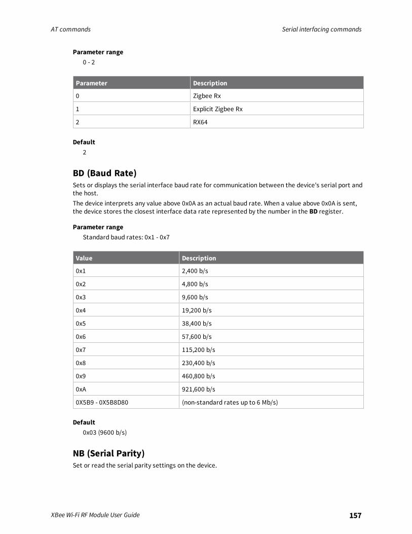
AT commands Serial interfacing commands
XBee Wi-Fi RF Module User Guide 157
Parameter range0 - 2
Parameter Description
0 Zigbee Rx
1 Explicit Zigbee Rx
2 RX64
Default2
BD (Baud Rate)Sets or displays the serial interface baud rate for communication between the device's serial port andthe host.The device interprets any value above 0x0A as an actual baud rate. When a value above 0x0A is sent,the device stores the closest interface data rate represented by the number in the BD register.
Parameter rangeStandard baud rates: 0x1 - 0x7
Value Description
0x1 2,400 b/s
0x2 4,800 b/s
0x3 9,600 b/s
0x4 19,200 b/s
0x5 38,400 b/s
0x6 57,600 b/s
0x7 115,200 b/s
0x8 230,400 b/s
0x9 460,800 b/s
0xA 921,600 b/s
0X5B9 - 0X5B8D80 (non-standard rates up to 6 Mb/s)
Default0x03 (9600 b/s)
NB (Serial Parity)Set or read the serial parity settings on the device.
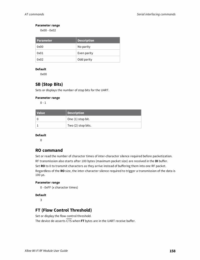
AT commands Serial interfacing commands
XBee Wi-Fi RF Module User Guide 158
Parameter range0x00 - 0x02
Parameter Description
0x00 No parity
0x01 Even parity
0x02 Odd parity
Default0x00
SB (Stop Bits)Sets or displays the number of stop bits for the UART.
Parameter range0 - 1
Value Description
0 One (1) stop bit.
1 Two (2) stop bits.
Default0
RO commandSet or read the number of character times of inter-character silence required before packetization.RF transmission also starts after 100 bytes (maximum packet size) are received in the DI buffer.Set RO to 0 to transmit characters as they arrive instead of buffering them into one RF packet.Regardless of the RO size, the inter-character silence required to trigger a transmission of the data is100 µs.
Parameter range0 - 0xFF (x character times)
Default3
FT (Flow Control Threshold)Set or display the flow control threshold.The device de-asserts CTS when FT bytes are in the UART receive buffer.

AT commands Serial interfacing commands
XBee Wi-Fi RF Module User Guide 159
Parameter range0x11 - 0x823
Default0x7F3
D7 (DIO7 Configuration)Sets or displays the DIO7/CTS configuration (TH pin 12/SMT pin 25).
Parameter range0, 1, 3 - 5
Parameter Description
0 Disabled
1 CTS flow control
3 Digital input
4 Digital output, low
5 Digital output, high
6 RS-485 Tx enable (low enable)
7 RS-485 Tx enable (high enable)
Default0x1
D6 (DIO6 Configuration)Sets or displays the DIO6/RTS configuration (TH pin 16/SMT pin 29).
Parameter range0, 1, 3 - 5
Parameter Description
0 Disabled
1 RTS flow control
2 N/A
3 Digital input
4 Digital output, low
5 Digital output, high
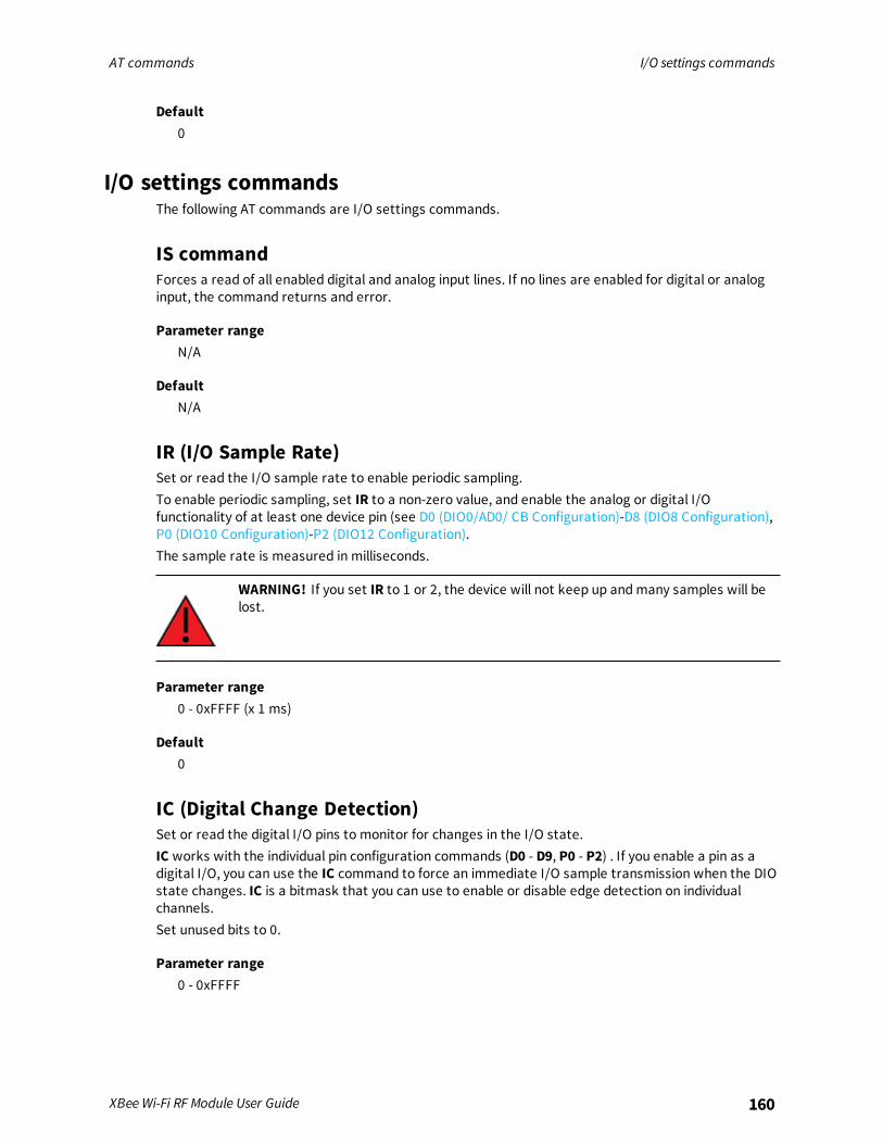
AT commands I/O settings commands
XBee Wi-Fi RF Module User Guide 160
Default0
I/O settings commandsThe following AT commands are I/O settings commands.
IS commandForces a read of all enabled digital and analog input lines. If no lines are enabled for digital or analoginput, the command returns and error.
Parameter rangeN/A
DefaultN/A
IR (I/O Sample Rate)Set or read the I/O sample rate to enable periodic sampling.To enable periodic sampling, set IR to a non-zero value, and enable the analog or digital I/Ofunctionality of at least one device pin (see D0 (DIO0/AD0/ CB Configuration)-D8 (DIO8 Configuration),P0 (DIO10 Configuration)-P2 (DIO12 Configuration).The sample rate is measured in milliseconds.
WARNING! If you set IR to 1 or 2, the device will not keep up andmany samples will belost.
Parameter range0 - 0xFFFF (x 1 ms)
Default0
IC (Digital Change Detection)Set or read the digital I/O pins to monitor for changes in the I/O state.IC works with the individual pin configuration commands (D0 - D9, P0 - P2) . If you enable a pin as adigital I/O, you can use the IC command to force an immediate I/O sample transmission when the DIOstate changes. IC is a bitmask that you can use to enable or disable edge detection on individualchannels.Set unused bits to 0.
Parameter range0 - 0xFFFF
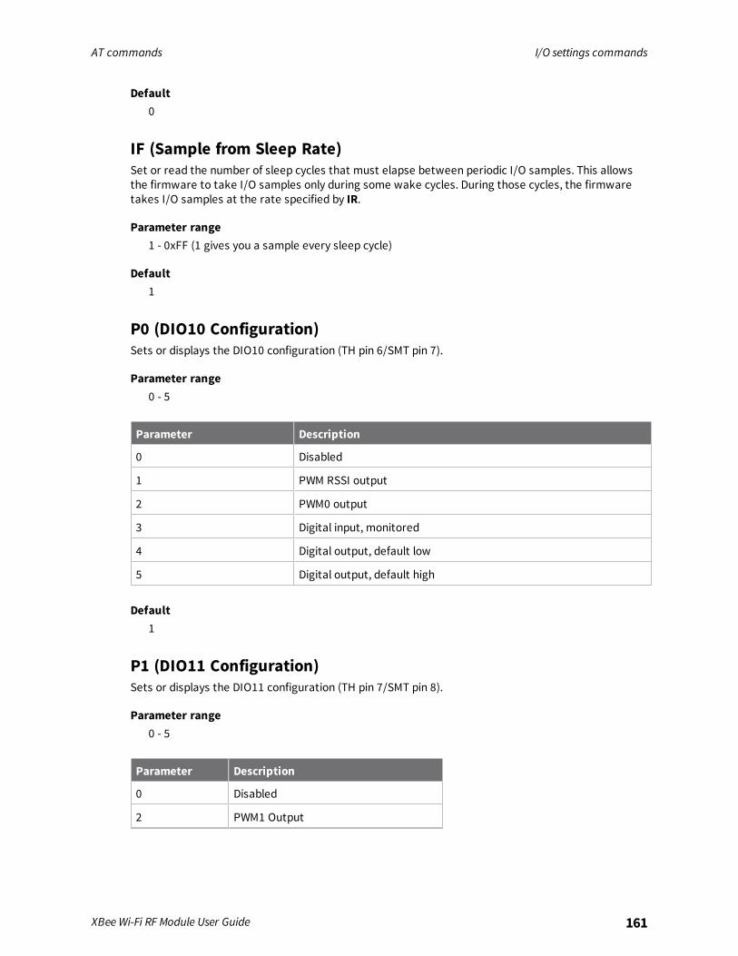
AT commands I/O settings commands
XBee Wi-Fi RF Module User Guide 161
Default0
IF (Sample from Sleep Rate)Set or read the number of sleep cycles that must elapse between periodic I/O samples. This allowsthe firmware to take I/O samples only during some wake cycles. During those cycles, the firmwaretakes I/O samples at the rate specified by IR.
Parameter range1 - 0xFF (1 gives you a sample every sleep cycle)
Default1
P0 (DIO10 Configuration)Sets or displays the DIO10 configuration (TH pin 6/SMT pin 7).
Parameter range0 - 5
Parameter Description
0 Disabled
1 PWM RSSI output
2 PWM0 output
3 Digital input, monitored
4 Digital output, default low
5 Digital output, default high
Default1
P1 (DIO11 Configuration)Sets or displays the DIO11 configuration (TH pin 7/SMT pin 8).
Parameter range0 - 5
Parameter Description
0 Disabled
2 PWM1 Output

AT commands I/O settings commands
XBee Wi-Fi RF Module User Guide 162
Parameter Description
3 Digital input, monitored
4 Digital output, default low
5 Digital output, default high
Default0
P2 (DIO12 Configuration)Sets or displays the DIO10 configuration (TH pin 6/SMT pin 7).
Parameter range0, 1, 3-6
Parameter Description
0 Disabled
1 SPI_MISO1
3 Digital input, monitored
4 Digital output, default low
5 Digital output, default high
6 TCP connection indicator
Default0
P3 (DOUT)Enables or disables output on the UART port.
Parameter range0, 1
Parameter Description
0 Disabled
1 Enabled
Default1
1Indicates that the option is available on the TH module, but not the SMT module.

AT commands I/O settings commands
XBee Wi-Fi RF Module User Guide 163
P4 DINEnables or disables input on UART port.
Parameter range0 - 1
Parameter Description
0 Disabled
1 Enabled
Default1
P5 (DIO15 Configuration)Sets or displays the DIO15 configuration (TH pin 4/SMT pin 17).This only applies to surface-mount devices.
Parameter range0, 1, 4, 5
Parameter Description
0 Disabled
1 SPI_MISO
4 Digital output, default low
5 Digital output, default high
Default1
P6 (DIO16 Configuration)Sets or displays the DIO16/SPI_MOSI configuration (TH pin 11/SMT pin 16).This only applies to surface-mount devices.
Parameter range0, 1, 4, 5
Parameter Description
0 Disabled
1 SPI_MOSI

AT commands I/O settings commands
XBee Wi-Fi RF Module User Guide 164
Parameter Description
4 Digital output, default low
5 Digital output, default high
Default1
P7 (DIO17 Configuration)Sets or displays the DIO17 configuration (TH pin 17/SMT pin 15).This only applies to surface-mount devices.
Parameter range0, 1, 4, 5
Parameter Description
0 Disabled
1 SPI_SSEL
4 Digital output, default low
5 Digital output, default high
Default1
P8 (DIO18 Configuration)Sets or displays the DIO18/SPI_CLK configuration (TH pin 18/SMT pin 14).This only applies to surface-mount devices.
Parameter range0, 1, 4, 5
Parameter Description
0 Disabled
1 SPI_CLK
4 Digital output, default low
5 Digital output, default high
Default1
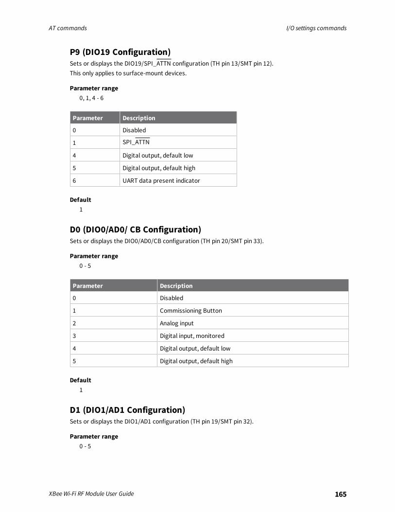
AT commands I/O settings commands
XBee Wi-Fi RF Module User Guide 165
P9 (DIO19 Configuration)Sets or displays the DIO19/SPI_ATTN configuration (TH pin 13/SMT pin 12).This only applies to surface-mount devices.
Parameter range0, 1, 4 - 6
Parameter Description
0 Disabled
1 SPI_ATTN
4 Digital output, default low
5 Digital output, default high
6 UART data present indicator
Default1
D0 (DIO0/AD0/ CB Configuration)Sets or displays the DIO0/AD0/CB configuration (TH pin 20/SMT pin 33).
Parameter range0 - 5
Parameter Description
0 Disabled
1 Commissioning Button
2 Analog input
3 Digital input, monitored
4 Digital output, default low
5 Digital output, default high
Default1
D1 (DIO1/AD1 Configuration)Sets or displays the DIO1/AD1 configuration (TH pin 19/SMT pin 32).
Parameter range0 - 5
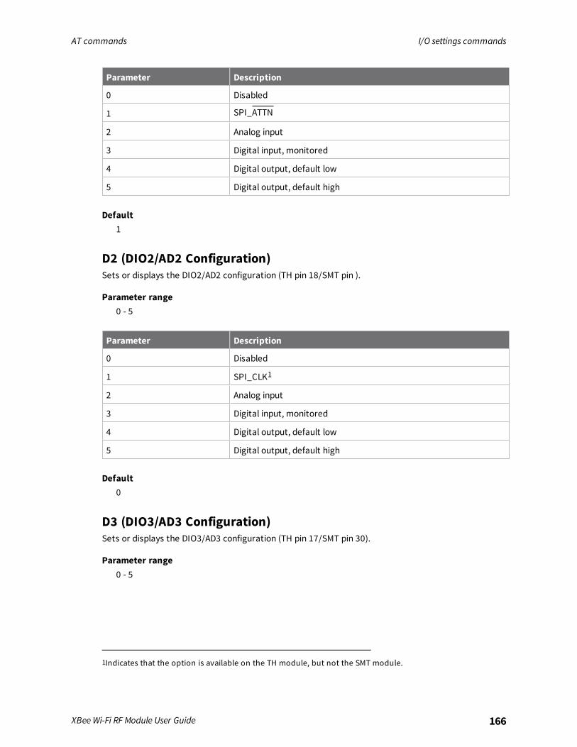
AT commands I/O settings commands
XBee Wi-Fi RF Module User Guide 166
Parameter Description
0 Disabled
1 SPI_ATTN
2 Analog input
3 Digital input, monitored
4 Digital output, default low
5 Digital output, default high
Default1
D2 (DIO2/AD2 Configuration)Sets or displays the DIO2/AD2 configuration (TH pin 18/SMT pin ).
Parameter range0 - 5
Parameter Description
0 Disabled
1 SPI_CLK1
2 Analog input
3 Digital input, monitored
4 Digital output, default low
5 Digital output, default high
Default0
D3 (DIO3/AD3 Configuration)Sets or displays the DIO3/AD3 configuration (TH pin 17/SMT pin 30).
Parameter range0 - 5
1Indicates that the option is available on the TH module, but not the SMT module.

AT commands I/O settings commands
XBee Wi-Fi RF Module User Guide 167
Parameter Description
0 Disabled
1 SPI Slave Select1
2 Analog input
3 Digital input, monitored
4 Digital output, default low
5 Digital output, default high
Default0
D4 (DIO4/AD4 Configuration)Sets or displays the DIO4/AD4 configuration (TH pin 11/SMT pin 24).
Parameter range0 - 5
Parameter Description
0 Disabled
1 SPI Slave Select2
2 Analog input
3 Digital input, monitored
4 Digital output, default low
5 Digital output, default high
Default0
D5 (DIO5 Configuration)Sets or displays the DIO5 configuration (TH pin 15/SMT pin 28).
Parameter range0, 1, 3 - 5
1Indicates that the option is available on the TH module, but not the SMT module.2Indicates that the option is available on the TH module, but not the SMT module.
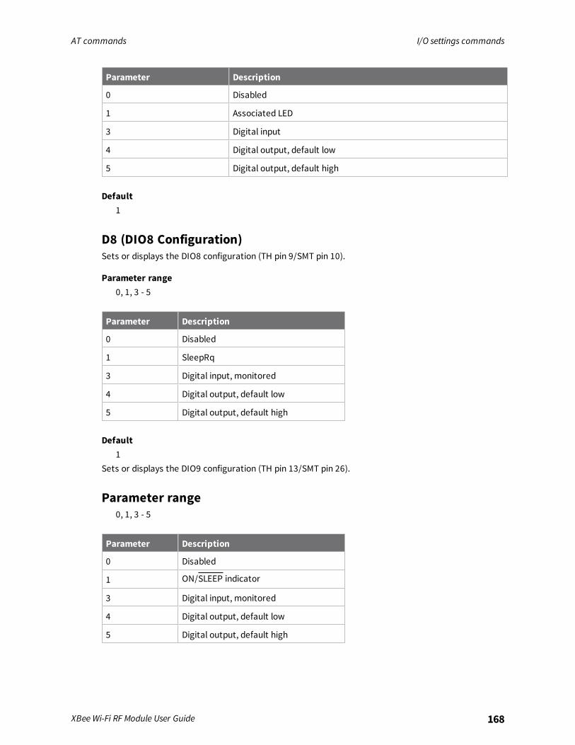
AT commands I/O settings commands
XBee Wi-Fi RF Module User Guide 168
Parameter Description
0 Disabled
1 Associated LED
3 Digital input
4 Digital output, default low
5 Digital output, default high
Default1
D8 (DIO8 Configuration)Sets or displays the DIO8 configuration (TH pin 9/SMT pin 10).
Parameter range0, 1, 3 - 5
Parameter Description
0 Disabled
1 SleepRq
3 Digital input, monitored
4 Digital output, default low
5 Digital output, default high
Default1
Sets or displays the DIO9 configuration (TH pin 13/SMT pin 26).
Parameter range0, 1, 3 - 5
Parameter Description
0 Disabled
1 ON/SLEEP indicator
3 Digital input, monitored
4 Digital output, default low
5 Digital output, default high
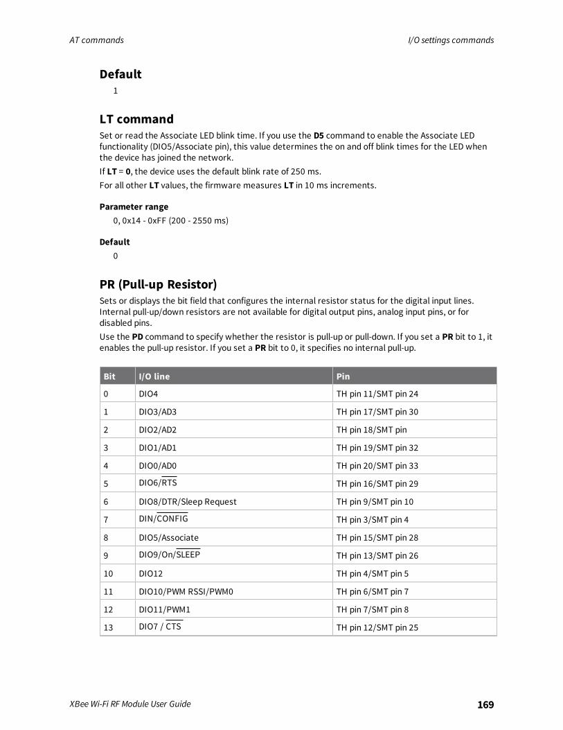
AT commands I/O settings commands
XBee Wi-Fi RF Module User Guide 169
Default1
LT commandSet or read the Associate LED blink time. If you use the D5 command to enable the Associate LEDfunctionality (DIO5/Associate pin), this value determines the on and off blink times for the LED whenthe device has joined the network.If LT = 0, the device uses the default blink rate of 250 ms.For all other LT values, the firmware measures LT in 10 ms increments.
Parameter range0, 0x14 - 0xFF (200 - 2550 ms)
Default0
PR (Pull-up Resistor)Sets or displays the bit field that configures the internal resistor status for the digital input lines.Internal pull-up/down resistors are not available for digital output pins, analog input pins, or fordisabled pins.Use the PD command to specify whether the resistor is pull-up or pull-down. If you set a PR bit to 1, itenables the pull-up resistor. If you set a PR bit to 0, it specifies no internal pull-up.
Bit I/O line Pin
0 DIO4 TH pin 11/SMT pin 24
1 DIO3/AD3 TH pin 17/SMT pin 30
2 DIO2/AD2 TH pin 18/SMT pin
3 DIO1/AD1 TH pin 19/SMT pin 32
4 DIO0/AD0 TH pin 20/SMT pin 33
5 DIO6/RTS TH pin 16/SMT pin 29
6 DIO8/DTR/Sleep Request TH pin 9/SMT pin 10
7 DIN/CONFIG TH pin 3/SMT pin 4
8 DIO5/Associate TH pin 15/SMT pin 28
9 DIO9/On/SLEEP TH pin 13/SMT pin 26
10 DIO12 TH pin 4/SMT pin 5
11 DIO10/PWM RSSI/PWM0 TH pin 6/SMT pin 7
12 DIO11/PWM1 TH pin 7/SMT pin 8
13 DIO7 / CTS TH pin 12/SMT pin 25
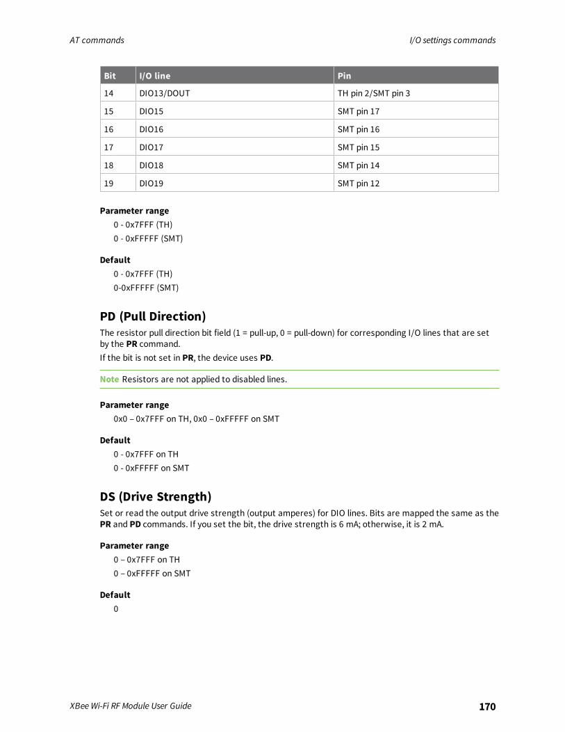
AT commands I/O settings commands
XBee Wi-Fi RF Module User Guide 170
Bit I/O line Pin
14 DIO13/DOUT TH pin 2/SMT pin 3
15 DIO15 SMT pin 17
16 DIO16 SMT pin 16
17 DIO17 SMT pin 15
18 DIO18 SMT pin 14
19 DIO19 SMT pin 12
Parameter range0 - 0x7FFF (TH)0 - 0xFFFFF (SMT)
Default0 - 0x7FFF (TH)0-0xFFFFF (SMT)
PD (Pull Direction)The resistor pull direction bit field (1 = pull-up, 0 = pull-down) for corresponding I/O lines that are setby the PR command.If the bit is not set in PR, the device uses PD.
Note Resistors are not applied to disabled lines.
Parameter range0x0 – 0x7FFF on TH, 0x0 – 0xFFFFF on SMT
Default0 - 0x7FFF on TH0 - 0xFFFFF on SMT
DS (Drive Strength)Set or read the output drive strength (output amperes) for DIO lines. Bits are mapped the same as thePR and PD commands. If you set the bit, the drive strength is 6 mA; otherwise, it is 2 mA.
Parameter range0 – 0x7FFF on TH0 – 0xFFFFF on SMT
Default0

AT commands I/O settings commands
XBee Wi-Fi RF Module User Guide 171
AV (Analog Voltage Reference)Set or read the analog voltage reference. This specifies the volts for an analog reading of 0X03FF,where a reading of 0x200 indicates a voltage input that is half of VREF. VREF may be one of the valuesin the following table.
Parameter range0, 1
Parameter Description
0 1.25 V reference
1 2.5 V reference
Default1
M0 (PWM0 Duty Cycle)Sets the duty cycle of PWM0 (TH pin 6/SMT pin 7) for P0 = 2, where a value of 0x200 is a 50% dutycycle.
Parameter range0 - 0x3FF
Default0
M1 (PWM1 Duty Cycle)Sets the duty cycle of PWM1 for P1 = 2, where a value of 0x200 is a 50% duty cycle.
Parameter range0 - 0x3FF
Default0
RP (RSSI PWM Timer)The PWM timer expiration in 0.1 seconds. RP sets the duration of pulse width modulation (PWM) signaloutput on the RSSI pin.
Parameter range0 - 0xFF (x 100 ms)
Default0x28 (four seconds)
AT commands Output Control
XBee Wi-Fi RF Module User Guide 172
Output ControlThe following AT commands are output control commands.
IO commandSet output pins to the designated level. Bit 0 corresponds with DIO0 and bit 1 with DIO1, up to bit 19that corresponds with DIO19. See Output control for a functional description.
Parameter range0 to 0x7FFF on through-hole0 to 0xFFFFF on surface-mount
DefaultN/A
OM (Output Mask)Sets the output mask for the IO command. If you set a bit, the corresponding bit in the IO command isenabled. If it is clear, then that same bit has no effect in the IO command.
Parameter range0 to 0x7FFF on through-hole0 to 0xFFFFF on surface-mount
Default0 to 0x7FFF on through-hole0 to 0xFFFFF on surface-mount
T0 (Set time to hold DIO0)Sets how long an output level programmed by bit 0 of the IO command is held in the selected statebefore reverting to its configured level. See Output control for a functional description.
Parameter range0 - 0x1770 (x 100 ms)
Default0
T1 (Set time to hold DIO1)Sets how long an output level programmed by bit 1 of the IO command is held in the selected statebefore reverting to its configured level. See Output control for a functional description.
Parameter range0 - 0x1770 (x 100 ms)
Default0
AT commands Output Control
XBee Wi-Fi RF Module User Guide 173
T2 (Set time to hold DIO2)Sets how long an output level programmed by bit 2 of the IO command is held in the selected statebefore reverting to its configured level. See Output control for a functional description.
Parameter range0 - 0x1770 (x 100 ms)
Default0
T3 (Set time to hold DIO3)Sets how long an output level programmed by bit 3 of the IO command is held in the selected statebefore reverting to its configured level. See Output control for a functional description.
Parameter range0 - 0x1770 (x 100 ms)
Default0
T4 (Set time to hold DIO4)Sets how long an output level programmed by bit 4 of the IO command is held in the selected statebefore reverting to its configured level. See Output control for a functional description.
Parameter range0 - 0x1770 (x 100 ms)
Default0
T5 (Set time to hold DIO5)Sets how long an output level programmed by bit 5 of the IO command is held in the selected statebefore reverting to its configured level. See Output control for a functional description.
Parameter range0 - 0x1770 (x 100 ms)
Default0
T6 (Set time to hold DIO6)Sets how long an output level programmed by bit 6 of the IO command is held in the selected statebefore reverting to its configured level. See Output control for a functional description.
Parameter range0 - 0x1770 (x 100 ms)
AT commands Output Control
XBee Wi-Fi RF Module User Guide 174
Default0
T7 (Set time to hold DIO7)Sets how long an output level programmed by bit 7 of the IO command is held in the selected statebefore reverting to its configured level. See Output control for a functional description.
Parameter range0 - 0x1770 (x 100 ms)
Default0
T8 (Set time to hold DIO8)Sets how long an output level programmed by bit 8 of the IO command is held in the selected statebefore reverting to its configured level. See Output control for a functional description.
Parameter range0 - 0x1770 (x 100 ms)
Default0
T9 (Set time to hold DIO9)Sets how long an output level programmed by bit 9 of the IO command is held in the selected statebefore reverting to its configured level. See Output control for a functional description.
Parameter range0 - 0x1770 (x 100 ms)
Default0
Q0 (Set time to hold DIO10)Sets how long an output level programmed by bit 10 of the IO command is held in the selected statebefore reverting to its configured level. See Output control for a functional description.
Parameter range0 - 0x1770 (x 100 ms)
Default0
Q1 (Set time to hold DIO11)Sets how long an output level programmed by bit 11 of the IO command is held in the selected statebefore reverting to its configured level. See Output control for a functional description.
AT commands Output Control
XBee Wi-Fi RF Module User Guide 175
Parameter range0 - 0x1770 (x 100 ms)
Default0
Q2 (Set time to hold DIO12)Sets how long an output level programmed by bit 12 of the IO command is held in the selected statebefore reverting to its configured level. See Output control for a functional description.
Parameter range0 - 0x1770 (x 100 ms)
Default0
Q3 (Set time to hold DIO13)Sets how long an output level programmed by bit 13 of the IO command is held in the selected statebefore reverting to its configured level. See Output control for a functional description.
Parameter range0 - 0x1770 (x 100 ms)
Default0
Q4 (Set time to hold DIO14)Sets how long an output level programmed by bit 14 of the IO command is held in the selected statebefore reverting to its configured level. See Output control for a functional description.
Parameter range0 - 0x1770 (x 100 ms)
Default0
Q5 (Set time to hold DIO15)Sets how long an output level programmed by bit 15 of the IO command is held in the selected statebefore reverting to its configured level. See Output control for a functional description.
Note This option is available on the SMT module, but not the TH module.
Parameter range0 - 0x1770 (x 100 ms)

AT commands Output Control
XBee Wi-Fi RF Module User Guide 176
Default0
Q6 (Set time to hold DIO16)Sets how long an output level programmed by bit 16 of the IO command is held in the selected statebefore reverting to its configured level. See Output control for a functional description.
Note This option is available on the SMT module, but not the TH module.
Parameter range0 - 0x1770 (x 100 ms)
Default0
Q7 (Set time to hold DIO17)Sets how long an output level programmed by bit 17 of the IO command is held in the selected statebefore reverting to its configured level. See Output control for a functional description.
Note This option is available on the SMT module, but not the TH module.
Parameter range0 - 0x1770 (x 100 ms)
Default0
Q8 (Set time to hold DIO18)Sets how long an output level programmed by bit 18 of the IO command is held in the selected statebefore reverting to its configured level. See Output control for a functional description.
Note This option is available on the SMT module, but not the TH module.
Parameter range0 - 0x1770 (x 100 ms)
Default0
Q9 (Set time to hold DIO19)Sets how long an output level programmed by bit 19 of IO command is held in the selected statebefore reverting to its configured level. See Output control for a functional description.
Note This option is available on the SMT device, but not the TH device.
AT commands Diagnostics interfacing
XBee Wi-Fi RF Module User Guide 177
Parameter range0 - 0x1770 (x 100 ms)
Default0
Diagnostics interfacingThe following AT commands are diagnostic commands.
VR commandReads the firmware version on a device.The firmware version returns four hexadecimal values (2 bytes) ABCD. Digits ABC are the main releasenumber and D is the revision number from the main release. B is a variant designator where 0meansstandard release.
Parameter range0 - 0xFFFF [read-only]
DefaultSet in firmware
HV commandRead the device's hardware version. Use this command to distinguish between different hardwareplatforms. The upper byte returns a value that is unique to each device type. The lower byte indicatesthe hardware revision.
Note XBee Wi-Fi RF Modules return 0x1Fxx for the HV command.
Parameter range0 - 0xFFFF [read-only]
DefaultSet in firmware
HS (Hardware Series)Read the device's hardware series number.The XBee Wi-Fi RF Module should return 0x601 for S6B.
Parameter rangeN/A
DefaultN/A

AT commands Diagnostics interfacing
XBee Wi-Fi RF Module User Guide 178
AI (Association Indication)Read information regarding last node join request.
Status code Meaning
0x00 Successfully joined an access point, established IP addresses and IP listening sockets.
0x01 Wi-Fi transceiver initialization in progress.
0x02 Wi-Fi transceiver initialized, but not yet scanning for access point.
0x13 Disconnecting from access point.
0x23 SSID not configured.
0x24 Encryption key invalid (either NULL or invalid length for WEP).
0x27 SSID was found, but join failed.
0x40 Waiting for WPA or WPA2 Authentication.
0x41 Device joined a network and is waiting for IP configuration to complete, which usuallymeans it is waiting for a DHCP provided address.
0x42 Device is joined, IP is configured, and listening sockets are being set up.
0xFF Device is currently scanning for the configured SSID.
Note New non-zero AI values may be added in later firmware versions. Applications should read AIuntil it returns 0x00, indicating a successful startup.
Parameter range0 - 0xFF [read-only]
DefaultN/A
DI (Device Cloud Indicator)Displays the current Remote Manager status for the XBee Wi-Fi RF Module.
Parameter range0 - 4
Value Description
0 Remote Manager is connected
1 Initial state
2 Attempting to connect to Remote Manager
3 Disconnecting from Remote Manager
4 Remote Manager not configured

AT commands Diagnostics interfacing
XBee Wi-Fi RF Module User Guide 179
DefaultN/A
AS commandScan for access points in the vicinity. Issue this command in commandmode or API mode to return thefollowing information:02 - Indicates scan type of 802.11 in this format unique to S6B.CH - Channel number in use by access point.ST - Security type where: 00=open, 01=WPA, 02=WPA2, and 03=WEP.LM - Link Margin (Signal strength in dB above sensitivity).ID - SSID of access point found.When you issue this command in commandmode, this record is displayed, one per line for each accesspoint found. Readable ASCII characters are outputs with a carriage return and each field on a newline.When you issue the command in API mode, each record (that is, each access point) outputs a separateAT Command Response frame - 0x88 with the above fields in binary format. The command terminateswith a null AT Command Response packet.In Commandmode, the AS command terminates with an additional carriage return.
Note This command is not available as a remote command. Also, this command gives an error ifassociated to an access point. AImust be 0x23 for this command to work which may be achieved byfirst using the NR command.
Parameter rangeN/A
DefaultN/A
TP commandDisplays the temperature of the XBee Wi-Fi RF Module in degrees Celsius. The temperature value isdisplayed in 8-bit two’s compliment format. For example, 0x1A = 26 °C, and 0xF6 = -10 °C.
Parameter range-30 to 85 °C
DefaultN/A
CK (Configuration Code)Reads the configuration code associated with the current AT command configuration.
Parameter range2 bytes

AT commands Command mode options
XBee Wi-Fi RF Module User Guide 180
DefaultN/A
%V (Supply Voltage)Displays the supply voltage of the device in mV units.
Parameter range3.1 to 3.5 V
DefaultN/A
LM (Link Margin)Reads the received signal strength (RSSI) in terms of dB units above sensitivity and reports 0xFF untilthe first reception after connection to access point.
Parameter range0 - 0xFF
DefaultN/A
Command mode optionsThe following commands are Commandmode option commands.
CT commandSets or displays the period of inactivity (that is, no valid commands received) after which the RFmodule automatically exits Command Mode and returns to Idle Mode. This time period can be up toten minutes.
Parameter range2 - 0x1770 (x 100 ms)
Default0x64 (10 seconds)
CN commandImmediately exits Command Mode and applies pending changes.
Note Whether Commandmode is exited using the CN command or by CT timing out, changes areapplied upon exit.
Parameter rangeN/A

AT commands Sleep commands
XBee Wi-Fi RF Module User Guide 181
DefaultN/A
GT commandSet the required period of silence before and after the command sequence characters of theCommandmode sequence (GT + CC + GT). The period of silence prevents inadvertently enteringCommandmode.
Parameter range0x2 - 0x0576 [x 1 ms] (max of 1.4 seconds)
Default0x3E8 (one second)
CC (Command Mode Character)Sets or displays the commandmode character used between guard times of the Commandmodesequence (GT + CC + CC + CC + GT). This sequence allows the device to enter into Commandmode.
Parameter range0 - 0xFF
Default0x2B (the ASCII plus character: +)
Sleep commandsThe following AT commands are sleep commands.
SM (Sleep Mode)Sets or displays the sleepmode of the device.The sleepmode determines how the device enters and exits a power saving sleep.Sleepmode is also affected by the SO command, option bit 6. See Sleepmodes for more informationabout sleepmodes.
Parameter range0, 1, 4, 5
Parameter Description
0 Normal. In this mode the device never sleeps.
1 Pin Sleep. In this modethe device honors the SLEEP_RQ pin. Set D8 (DIO8 Configuration) to the sleep requestfunction: 1.

AT commands Sleep commands
XBee Wi-Fi RF Module User Guide 182
Parameter Description
4 Cyclic Sleep. In this modethe device repeatedly sleeps for the value specified by SP and spends ST time awake.
5 Cyclic Sleep with Pin Wake. In this mode the device acts as in Cyclic Sleep but does notsleep if the SLEEP_RQ pin is inactive, allowing the device to be kept awake or woken bythe connected system.
Default0
SP (Sleep Period)This value determines how long the device sleeps, up to 24 hours or 86,400 seconds. This correspondsto 0x83d600 in 10 ms units.
Parameter range0x1 - 0x83D600 (x 10 ms)
Default0xC8 (2 seconds)
SO commandSet or read the sleepmode options.
Bit Option
0x40 Stay associated with AP during sleep. Draw more current during sleep with this optionenabled, but also avoid data loss.
0x100 For cyclic sleep, ST specifies the time before returning to sleep. With this bit set, newreceptions from either the serial or the RF port do not restart the ST timer. Currentimplementation does not support this bit being turned off.
Parameter range0 - 0x01FF
Default0x100
WH (Wake Host)Sets or displays the wake host timer value.If you set WH to a non-zero value, this timer specifies a time in milliseconds that the device delaysafter waking from sleep before sending data out the UART or transmitting an I/O sample. If the devicereceives serial characters, the WH timer stops immediately.
Parameter range0 - 0xFFFF (x 1 ms)
AT commands Execution commands
XBee Wi-Fi RF Module User Guide 183
Default0
ST (Wake Time)Sets or displays the time to spend awake in cyclic sleepmodes.If there is data to transmit or receive after ST expires, those actions occur before the module goes tosleep. The maximum wake time is 3600 seconds.
Parameter range0x1 - 0x36EE80 (x 1 ms)
Default0x7D0 (3 seconds)
SA commandTime to wait for association before entering deep sleep. Wakeup from deep sleep is much faster ifassociation occurs before going to sleep.
Parameter range0x1 – 0x36EE80 (x1 ms)
Default0x2710 (10 seconds)
Execution commandsThe location where most AT commands set or query register values, execution commands execute anaction on the device. Execution commands are executed immediately and do not require changes tobe applied.
AC (Apply Changes)Applies changes to all command registers and applies queued command register values. For example,changing the serial interface rate with the BD command does not change the UART interface rateuntil changes are applied with the AC command. The CN command and 0x08 API command frame alsoapply changes.
Parameter rangeN/A
DefaultN/A
WR commandWrites parameter values to non-volatile memory so that parameter modifications persist throughsubsequent resets.
AT commands Execution commands
XBee Wi-Fi RF Module User Guide 184
Note Once you issue a WR command, do not send any additional characters to the device until afteryou receive the OK response. Use the WR command sparingly to preserve flash.
Parameter rangeN/A
DefaultN/A
RE commandRestore device parameters to factory defaults.
Parameter rangeN/A
DefaultN/A
FR (Software Reset)Resets the device. The device responds immediately with anOK and performs a software resetapproximately two seconds later.
Parameter rangeN/A
DefaultN/A
NR (Network Reset)Resets the network layer. For Wi-Fi, this means disassociating from the access point and set SSID toNULL, thereby preventing the node from immediately establishing the same connection with the sameaccess point. This command also clears security settings (EE and PK).
Note NR andNR0 both perform the same function andmay be used interchangeably.
Parameter range0
DefaultN/A
CB commandUse CB to simulate commissioning pushbutton presses in software. You can issue the CB commandeven if the Commissioning Button functionality is disabled (D0 is not set to 1).See The Commissioning Button.
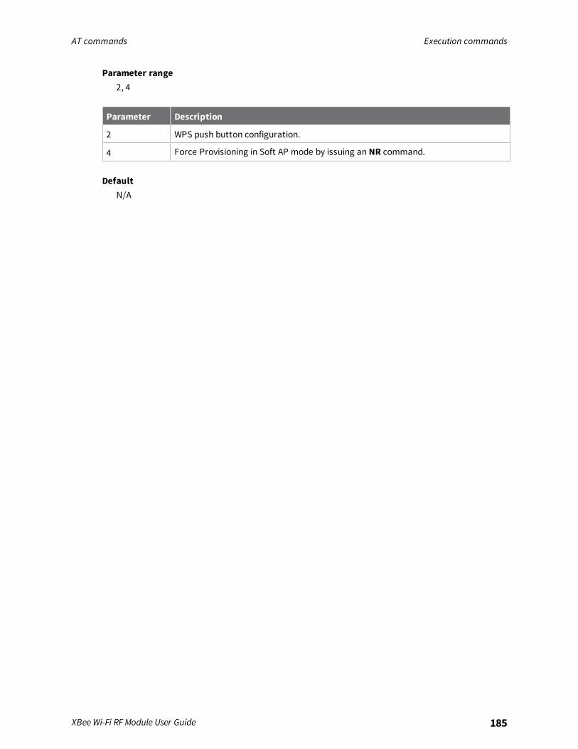
AT commands Execution commands
XBee Wi-Fi RF Module User Guide 185
Parameter range2, 4
Parameter Description
2 WPS push button configuration.
4 Force Provisioning in Soft AP mode by issuing an NR command.
DefaultN/A
Regulatory information
Systems that contain XBee Wi-Fi RF Modules inherit Digi certifications.
United States (FCC) 187Europe (CE) 195Canada (IC) 197Australia (RCM)/New Zealand (R-NZ) 198Brazil (ANATEL) 198
XBee Wi-Fi RF Module User Guide 186
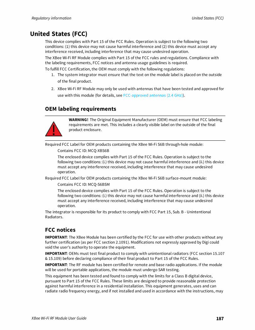
Regulatory information United States (FCC)
XBee Wi-Fi RF Module User Guide 187
United States (FCC)This device complies with Part 15 of the FCC Rules. Operation is subject to the following twoconditions: (1) this device may not cause harmful interference and (2) this device must accept anyinterference received, including interference that may cause undesired operation.The XBee Wi-Fi RF Module complies with Part 15 of the FCC rules and regulations. Compliance withthe labeling requirements, FCC notices and antenna usage guidelines is required.To fulfill FCC Certification, the OEM must comply with the following regulations:
1. The system integrator must ensure that the text on the module label is placed on the outsideof the final product.
2. XBee Wi-Fi RF Module may only be used with antennas that have been tested and approved foruse with this module (for details, see FCC-approved antennas (2.4 GHz)).
OEM labeling requirements
WARNING! The Original Equipment Manufacturer (OEM) must ensure that FCC labelingrequirements are met. This includes a clearly visible label on the outside of the finalproduct enclosure.
Required FCC Label for OEM products containing the XBee Wi-Fi S6B through-hole module:Contains FCC ID: MCQ-XBS6BThe enclosed device complies with Part 15 of the FCC Rules. Operation is subject to thefollowing two conditions: (i.) this device may not cause harmful interference and (ii.) this devicemust accept any interference received, including interference that may cause undesiredoperation.
Required FCC Label for OEM products containing the XBee Wi-Fi S6B surface-mount module:Contains FCC ID: MCQ-S6BSMThe enclosed device complies with Part 15 of the FCC Rules. Operation is subject to thefollowing two conditions: (i.) this device may not cause harmful interference and (ii.) this devicemust accept any interference received, including interference that may cause undesiredoperation.
The integrator is responsible for its product to comply with FCC Part 15, Sub. B - UnintentionalRadiators.
FCC noticesIMPORTANT: The XBee Module has been certified by the FCC for use with other products without anyfurther certification (as per FCC section 2.1091). Modifications not expressly approved by Digi couldvoid the user's authority to operate the equipment.IMPORTANT: OEMs must test final product to comply with unintentional radiators (FCC section 15.107& 15.109) before declaring compliance of their final product to Part 15 of the FCC Rules.IMPORTANT: The RF module has been certified for remote and base radio applications. If the modulewill be used for portable applications, the module must undergo SAR testing.This equipment has been tested and found to comply with the limits for a Class B digital device,pursuant to Part 15 of the FCC Rules. These limits are designed to provide reasonable protectionagainst harmful interference in a residential installation. This equipment generates, uses and canradiate radio frequency energy, and if not installed and used in accordance with the instructions, may

Regulatory information United States (FCC)
XBee Wi-Fi RF Module User Guide 188
cause harmful interference to radio communications. However, there is no guarantee thatinterference will not occur in a particular installation.If this equipment does cause harmful interference to radio or television reception, which can bedetermined by turning the equipment off and on, the user is encouraged to try to correct theinterference by one or more of the following measures: Re-orient or relocate the receiving antenna,Increase the separation between the equipment and receiver, Connect equipment and receiver tooutlets on different circuits, or Consult the dealer or an experienced radio/TV technician for help.
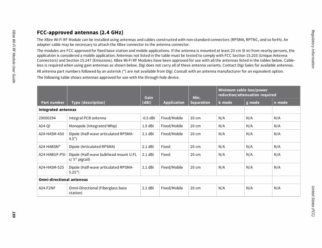
Regulatoryinform
ationUnited
States(FCC)
XBeeWi-FiRF
Module
UserGuide189
FCC-approved antennas (2.4 GHz)The XBee Wi-Fi RF Module can be installed using antennas and cables constructed with non-standard connectors (RPSMA, RPTNC, and so forth). Anadapter cable may be necessary to attach the XBee connector to the antenna connector.The modules are FCC approved for fixed base station andmobile applications. If the antenna is mounted at least 20 cm (8 in) from nearby persons, theapplication is considered a mobile application. Antennas not listed in the table must be tested to comply with FCC Section 15.203 (Unique AntennaConnectors) and Section 15.247 (Emissions). XBee Wi-Fi RF Modules have been approved for use with all the antennas listed in the tables below. Cable-loss is required when using gain antennas as shown below. Digi does not carry all of these antenna variants. Contact Digi Sales for available antennas.All antenna part numbers followed by an asterisk (*) are not available from Digi. Consult with an antenna manufacturer for an equivalent option.The following table shows antennas approved for use with the through-hole device.
Part number Type (description)Gain
(dBi) ApplicationMin.
Separation
Minimum cable loss/powerreduction/attenuation required
b mode g mode n mode
Integrated antennas
29000294 Integral PCB antenna -0.5 dBi Fixed/Mobile 20 cm N/A N/A N/A
A24-QI Monopole (Integrated Whip) 1.5 dBi Fixed/Mobile 20 cm N/A N/A N/A
A24-HASM-450 Dipole (Half-wave articulated RPSMA-4.5")
2.1 dBi Fixed/Mobile 20 cm N/A N/A N/A
A24-HABSM* Dipole (Articulated RPSMA) 2.1 dBi Fixed 20 cm N/A N/A N/A
A24-HABUF-P5I Dipole (Half-wave bulkheadmount U.FLs/ 5" pigtail)
2.1 dBi Fixed 20 cm N/A N/A N/A
A24-HASM-525 Dipole (Half-wave articulated RPSMA-5.25")
2.1 dBi Fixed/Mobile 20 cm N/A N/A N/A
Omni-directional antennas
A24-F2NF Omni-Directional (Fiberglass basestation)
2.1 dBi Fixed/Mobile 20 cm N/A N/A N/A

Regulatoryinform
ationUnited
States(FCC)
XBeeWi-FiRF
Module
UserGuide190
Part number Type (description)Gain
(dBi) ApplicationMin.
Separation
Minimum cable loss/powerreduction/attenuation required
b mode g mode n mode
A24-F3NF Omni-Directional (Fiberglass basestation)
3.0 dBi Fixed/Mobile 20 cm N/A N/A N/A
A24-F5NF Omni-Directional (Fiberglass basestation)
5.0 dBi Fixed 20 cm N/A N/A N/A
A24-F8NF Omni-Directional (Fiberglass basestation)
8.0 dBi Fixed 2 m N/A 0.4 dB 0.4 dB
A24-F9NF Omni-Directional (Fiberglass basestation)
9.5 dBi Fixed 2 m 0.4 dB 2.4 dB 2.4 dB
A24-F10NF Omni-Directional (Fiberglass basestation)
10 dBi Fixed 2 m 0.9 dB 2.9 dB 2.9 dB
A24-F12NF Omni-Directional (Fiberglass basestation)
12 dBi Fixed 2 m 2.9 dB 4.9 dB 4.9 dB
A24-F15NF Omni-Directional (Fiberglass basestation)
15 dBi Fixed 2 m 5.9 dB 7.9 dB 7.9 dB
A24-W7NF Omni-Directional (base station) 7.2 dBi Fixed 2 m N/A 0.1 dB 0.1 dB
A24-M7NF Omni-directional (Mag-mount basestation)
7.2 dBi Fixed 2 m N/A 0.1 dB 0.1 dB
Panel class antennas
A24-P8SF Flat Panel 8.5 dBi Fixed 2 m N/A 1.4 dB 1.4 dB
A24-P8NF Flat Panel 8.5 dBi Fixed 3 m N/A 1.4 dB 1.4 dB
A24-P13NF Flat Panel 13 dBi Fixed 4 m 3.9 dB 5.9 dB 5.9 dB
A24-P14NF Flat Panel 14 dBi Fixed 5 m 4.9 dB 6.9 dB 6.9 dB
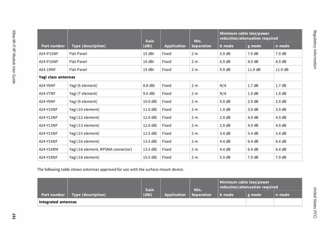
Regulatoryinform
ationUnited
States(FCC)
XBeeWi-FiRF
Module
UserGuide191
Part number Type (description)Gain
(dBi) ApplicationMin.
Separation
Minimum cable loss/powerreduction/attenuation required
b mode g mode n mode
A24-P15NF Flat Panel 15 dBi Fixed 2 m 5.9 dB 7.9 dB 7.9 dB
A24-P16NF Flat Panel 16 dBi Fixed 2 m 6.9 dB 8.9 dB 8.9 dB
A24-19NF Flat Panel 19 dBi Fixed 2 m 9.9 dB 11.9 dB 11.9 dB
Yagi class antennas
A24-Y6NF Yagi (6 element) 8.8 dBi Fixed 2 m N/A 1.7 dB 1.7 dB
A24-Y7NF Yagi (7 element) 9.0 dBi Fixed 2 m N/A 1.9 dB 1.9 dB
A24-Y9NF Yagi (9 element) 10.0 dBi Fixed 2 m 0.9 dB 2.9 dB 2.9 dB
A24-Y10NF Yagi (10 element) 11.0 dBi Fixed 2 m 1.9 dB 3.9 dB 3.9 dB
A24-Y12NF Yagi (12 element) 12.0 dBi Fixed 2 m 2.9 dB 4.9 dB 4.9 dB
A24-Y13NF Yagi (13 element) 12.0 dBi Fixed 2 m 2.9 dB 4.9 dB 4.9 dB
A24-Y15NF Yagi (15 element) 12.5 dBi Fixed 2 m 3.4 dB 5.4 dB 5.4 dB
A24-Y16NF Yagi (16 element) 13.5 dBi Fixed 2 m 4.4 dB 6.4 dB 6.4 dB
A24-Y16RM Yagi (16 element, RPSMA connector) 13.5 dBi Fixed 2 m 4.4 dB 6.4 dB 6.4 dB
A24-Y18NF Yagi (18 element) 15.0 dBi Fixed 2 m 5.9 dB 7.9 dB 7.9 dB
The following table shows antennas approved for use with the surface-mount device.
Part number Type (description)Gain
(dBi) ApplicationMin.
Separation
Minimum cable loss/powerreduction/attenuation required
b mode g mode n mode
Integrated antennas
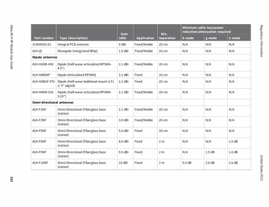
Regulatoryinform
ationUnited
States(FCC)
XBeeWi-FiRF
Module
UserGuide192
Part number Type (description)Gain
(dBi) ApplicationMin.
Separation
Minimum cable loss/powerreduction/attenuation required
b mode g mode n mode
31000005-01 Integral PCB antenna 0 dBi Fixed/Mobile 20 cm N/A N/A N/A
A24-QI Monopole (Integrated Whip) 1.5 dBi Fixed/Mobile 20 cm N/A N/A N/A
Dipole antennas
A24-HASM-450 Dipole (Half-wave articulated RPSMA-4.5")
2.1 dBi Fixed/Mobile 20 cm N/A N/A N/A
A24-HABSM* Dipole (Articulated RPSMA) 2.1 dBi Fixed 20 cm N/A N/A N/A
A24-HABUF-P5I Dipole (Half-wave bulkheadmount U.FLs/ 5" pigtail)
2.1 dBi Fixed 20 cm N/A N/A N/A
A24-HASM-525 Dipole (Half-wave articulated RPSMA-5.25")
2.1 dBi Fixed/Mobile 20 cm N/A N/A N/A
Omni-directional antennas
A24-F2NF Omni-Directional (Fiberglass basestation)
2.1 dBi Fixed/Mobile 20 cm N/A N/A N/A
A24-F3NF Omni-Directional (Fiberglass basestation)
3.0 dBi Fixed/Mobile 20 cm N/A N/A N/A
A24-F5NF Omni-Directional (Fiberglass basestation)
5.0 dBi Fixed 20 cm N/A N/A N/A
A24-F8NF Omni-Directional (Fiberglass basestation)
8.0 dBi Fixed 2 m N/A N/A 1.5 dB
A24-F9NF Omni-Directional (Fiberglass basestation)
9.5 dBi Fixed 2 m N/A 1.5 dB 1.0 dB
A24-F10NF Omni-Directional (Fiberglass basestation)
10 dBi Fixed 2 m 0.5 dB 2.0 dB 2.5 dB
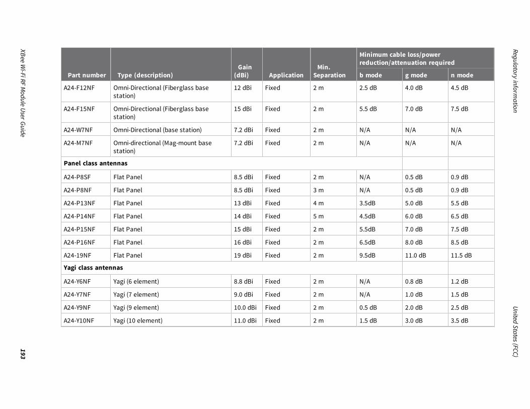
Regulatoryinform
ationUnited
States(FCC)
XBeeWi-FiRF
Module
UserGuide193
Part number Type (description)Gain
(dBi) ApplicationMin.
Separation
Minimum cable loss/powerreduction/attenuation required
b mode g mode n mode
A24-F12NF Omni-Directional (Fiberglass basestation)
12 dBi Fixed 2 m 2.5 dB 4.0 dB 4.5 dB
A24-F15NF Omni-Directional (Fiberglass basestation)
15 dBi Fixed 2 m 5.5 dB 7.0 dB 7.5 dB
A24-W7NF Omni-Directional (base station) 7.2 dBi Fixed 2 m N/A N/A N/A
A24-M7NF Omni-directional (Mag-mount basestation)
7.2 dBi Fixed 2 m N/A N/A N/A
Panel class antennas
A24-P8SF Flat Panel 8.5 dBi Fixed 2 m N/A 0.5 dB 0.9 dB
A24-P8NF Flat Panel 8.5 dBi Fixed 3 m N/A 0.5 dB 0.9 dB
A24-P13NF Flat Panel 13 dBi Fixed 4 m 3.5dB 5.0 dB 5.5 dB
A24-P14NF Flat Panel 14 dBi Fixed 5 m 4.5dB 6.0 dB 6.5 dB
A24-P15NF Flat Panel 15 dBi Fixed 2 m 5.5dB 7.0 dB 7.5 dB
A24-P16NF Flat Panel 16 dBi Fixed 2 m 6.5dB 8.0 dB 8.5 dB
A24-19NF Flat Panel 19 dBi Fixed 2 m 9.5dB 11.0 dB 11.5 dB
Yagi class antennas
A24-Y6NF Yagi (6 element) 8.8 dBi Fixed 2 m N/A 0.8 dB 1.2 dB
A24-Y7NF Yagi (7 element) 9.0 dBi Fixed 2 m N/A 1.0 dB 1.5 dB
A24-Y9NF Yagi (9 element) 10.0 dBi Fixed 2 m 0.5 dB 2.0 dB 2.5 dB
A24-Y10NF Yagi (10 element) 11.0 dBi Fixed 2 m 1.5 dB 3.0 dB 3.5 dB
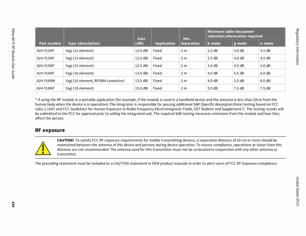
Regulatoryinform
ationUnited
States(FCC)
XBeeWi-FiRF
Module
UserGuide194
Part number Type (description)Gain
(dBi) ApplicationMin.
Separation
Minimum cable loss/powerreduction/attenuation required
b mode g mode n mode
A24-Y12NF Yagi (12 element) 12.0 dBi Fixed 2 m 2.5 dB 4.0 dB 4.5 dB
A24-Y13NF Yagi (13 element) 12.0 dBi Fixed 2 m 2.5 dB 4.0 dB 4.5 dB
A24-Y15NF Yagi (15 element) 12.5 dBi Fixed 2 m 3.0 dB 4.5 dB 5.0 dB
A24-Y16NF Yagi (16 element) 13.5 dBi Fixed 2 m 4.0 dB 5.5 dB 6.0 dB
A24-Y16RM Yagi (16 element, RPSMA connector) 13.5 dBi Fixed 2 m 4.0 dB 5.5 dB 6.0 dB
A24-Y18NF Yagi (18 element) 15.0 dBi Fixed 2 m 5.5 dB 7.0 dB 7.5 dB
* If using the RF module in a portable application (for example, if the module is used in a handheld device and the antenna is less than 20cm from thehuman body when the device is in operation): The integrator is responsible for passing additional SAR (Specific Absorption Rate) testing based on FCCrules 2.1091 and FCC Guidelines for Human Exposure to Radio Frequency Electromagnetic Fields, OET Bulletin and Supplement C. The testing results willbe submitted to the FCC for approval prior to selling the integrated unit. The required SAR testing measures emissions from the module and how theyaffect the person.
RF exposure
CAUTION! To satisfy FCC RF exposure requirements for mobile transmitting devices, a separation distance of 20 cm or more should bemaintained between the antenna of this device and persons during device operation. To ensure compliance, operations at closer than thisdistance are not recommended. The antenna used for this transmitter must not be co-located in conjunction with any other antenna ortransmitter.
The preceding statement must be included as a CAUTION statement in OEM product manuals in order to alert users of FCC RF Exposure compliance.
Regulatory information Europe (CE)
XBee Wi-Fi RF Module User Guide 195
Europe (CE)The XBee Wi-Fi RF radio modules are certified for use in several European countries. For a completelist, refer to www.digi.com/resources/certifications.If the XBee Wi-Fi is incorporated into a product, the manufacturer must ensure compliance of the finalproduct with articles 3.1a and 3.1b of the RE Directive (Radio Equipment Directive). A Declaration ofConformity must be issued for each of these standards and kept on file as described in the REDirective (Radio Equipment Directive).Furthermore, the manufacturer must maintain a copy of the XBee Wi-Fi user manual documentationand ensure the final product does not exceed the specified power ratings, antenna specifications,and/or installation requirements as specified in the user manual. If any of these specifications areexceeded in the final product, a submission must be made to a notified body for compliance testing toall required standards.
Maximum power and frequency specificationsFor the XBee S6B through-hole device:
n Maximum RF output power: 95.06 mW (19.78 dBm) Equivalent Isotropically Radiated Power(EIRP).
The radio can transmit on the following 13 802.11 channels:n 2412, 2417, 2422, 2427, 2432, 2437, 2442, 2447, 2452, 2457, 2462, 2467, 2472.
For the XBee S6B surface-mount device:n Maximum RF output power: 81.47 mW (19.11 dBm) EIRP.
The radio can transmit on the following 13 802.11 channels:n 2412, 2417, 2422, 2427, 2432, 2437, 2442, 2447, 2452, 2457, 2462, 2467, 2472.
OEM labeling requirementsThe 'CE' marking must be affixed to a visible location on the OEM product.

Regulatory information Europe (CE)
XBee Wi-Fi RF Module User Guide 196
CE labeling requirements
The CE mark shall consist of the initials “CE” taking the following form:n If the CE marking is reduced or enlarged, the proportions given in the above graduated
drawing must be respected.
n The CE marking must have a height of at least 5 mm except where this is not possible onaccount of the nature of the apparatus.
n The CE marking must be affixed visibly, legibly, and indelibly.
Declarations of conformityDigi has issued Declarations of Conformity for the (product name) concerning emissions, EMC, andsafety. For more information, see www.digi.com/resources/certifications.
Important noteDigi customers assume full responsibility for learning andmeeting the required guidelines for eachcountry in their distribution market. Refer to the radio regulatory agency in the desired countries ofoperation for more information.
Approved antennasWhen integrating high-gain antennas, European regulations stipulate EIRP power maximums.All antenna part numbers followed by an asterisk (*) are not available from Digi. Consult with anantenna manufacturer for an equivalent option.The following antennas are approved for use with the XBee Wi-Fi RF Module:
n Dipole (2.1 dBi, omni-directional, articulated RPSMA, Digi part number A24-HABSM*)
n PCB antenna (0 dBi)
n Wire whip antenna (1.5 dBi)

Regulatory information Canada (IC)
XBee Wi-Fi RF Module User Guide 197
Canada (IC)This device complies with Industry Canada licence-exempt RSS standard(s). Operation is subject tothe following two conditions: (1) this device may not cause interference, and (2) this device mustaccept any interference, including interference that may cause undesired operation of the device.Le présent appareil est conforme aux CNR d'Industrie Canada applicables aux appareils radio exemptsde licence. L'exploitation est autorisée aux deux conditions suivantes: (1) l'appareil ne doit pasproduire de brouillage, et (2) l'utilisateur de l'appareil doit accepter tout brouillage radioélectriquesubi, même si le brouillage est susceptible d'en compromettre le fonctionnement.
Labeling requirementsLabeling requirements for Industry Canada are similar to those of the FCC. A clearly visible label onthe outside of the final product enclosure must display the following text.XBee Wi-Fi Through-hole:Contains Model XBEES6B Radio, IC: 1846A-XBS6BXBee Wi-Fi Surface Mount:Contains Model S6BSM Radio, IC: 1846A-S6BSMThe integrator is responsible for its product to comply with IC ICES-003 & FCC Part 15, Sub. B -Unintentional Radiators. ICES-003 is the same as FCC Part 15 Sub. B and Industry Canada acceptsFCC test report or CISPR 22 test report for compliance with ICES-003.
Transmitters with detachable antennasThis radio transmitter (IC: 1846A-XBS6B and IC: 1846A-S6BSM) has been approved by Industry Canadato operate with the antenna types listed in the tables above with the maximum permissible gain andrequired antenna impedance for each antenna type indicated. Antenna types not included in this list,having a gain greater than the maximum gain indicated for that type, are strictly prohibited for usewith this device.Le présent émetteur radio (IC: 1846A-XBS6B et IC: 1846A-S6BSM) a été approuvé par IndustrieCanada pour fonctionner avec les types d'antenne énumérés ci-dessous et ayant un gain admissiblemaximal et l'impédance requise pour chaque type d'antenne. Les types d'antenne non inclus danscette liste, ou dont le gain est supérieur au gain maximal indiqué, sont strictement interdits pourl'exploitation de l'émetteur.
Detachable antennaUnder Industry Canada regulations, this radio transmitter may only operate using an antenna of atype andmaximum (or lesser) gain approved for the transmitter by Industry Canada. To reducepotential radio interference to other users, the antenna type and its gain should be so chosen that theequivalent isotropically radiated power (EIRP) is not more than that necessary for successfulcommunication.Conformément à la réglementation d'Industrie Canada, le présent émetteur radio peut fonctionneravec une antenne d'un type et d'un gain maximal (ou inférieur) approuvé pour l'émetteur par IndustrieCanada. Dans le but de réduire les risques de brouillage radioélectrique à l'intention des autresutilisateurs, il faut choisir le type d'antenne et son gain de sorte que la puissance isotrope rayonnéeéquivalente (p.i.r.e.) ne dépasse pas l'intensité nécessaire àl'établissement d'une communicationsatisfaisante.

Regulatory information Australia (RCM)/New Zealand (R-NZ)
XBee Wi-Fi RF Module User Guide 198
Australia (RCM)/New Zealand (R-NZ)These modules comply with requirements to be used in end products in Australia and New Zealand. Allproducts with EMC and radio communications must have registered RCM and R-NZ marks.Registration to use the compliance mark will only be accepted from Australia or New Zealandmanufacturers or importers, or their agents.In order to have a RCM or R-NZ mark on an end product, a company must comply with a or b below.
a. have a company presence in Australia or New Zealand.
b. have a company/distributor/agent in Australia or New Zealand that will sponsor the importingof the end product.
Contact Digi for questions related to locating a contact in Australia and New Zealand.
Brazil (ANATEL)These modules comply with Brazil ANATEL standards in Resolution No. 506. The following informationis required in the user manual for the product containing the radio and on the product containing theradio (in Portuguese):Anatel homologation number to be stamped on product label:
ANATEL: 2672-13-1209Anatel homologation label to be stamped on the user manual.
Resolution 506 warning to be stamped on the user manual:

Manufacturing information
The XBee Wi-Fi RF Module is designed for surface-mounting on the OEM PCB. It has castellated padsto allow for easy solder attaching and inspection. The pads are all located on the edge of the device sothere are no hidden solder joints on these devices.
Recommended solder reflow cycle 200Recommended footprint 200Mount the devices 202Flux and cleaning 203Rework 204
XBee Wi-Fi RF Module User Guide 199

Manufacturing information Recommended solder reflow cycle
XBee Wi-Fi RF Module User Guide 200
Recommended solder reflow cycleThe following table lists the recommended solder reflow cycle. The chart shows the temperaturesetting and the time to reach the temperature.
Time (seconds) Temperature (°C)
30 65
60 100
90 135
120 160
150 195
180 240
210 260
The maximum temperature should not exceed 260 °C.The device reflows during this cycle, andmust not be reflowed upside down. Be careful not to jar thedevice while the solder is molten, as parts inside the device can be removed from their requiredlocations.Hand soldering is possible and should be done in accordance with approved standards.This device has a Moisture Sensitivity Level (MSL) of 3.
Recommended footprintWe recommend that you use the PCB footprints in the following drawings for surface mounting. Thefirst drawing shows the surface mount module.
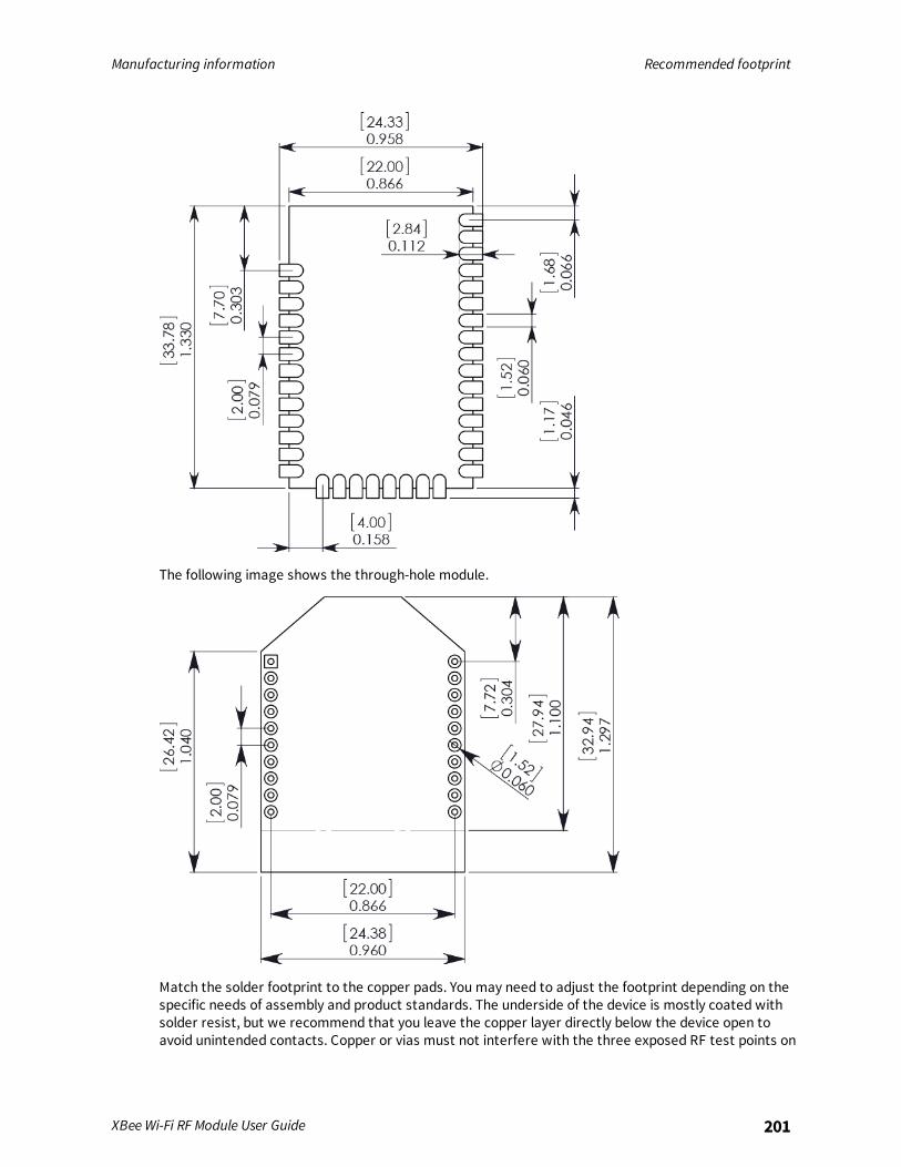
Manufacturing information Recommended footprint
XBee Wi-Fi RF Module User Guide 201
The following image shows the through-hole module.
Match the solder footprint to the copper pads. You may need to adjust the footprint depending on thespecific needs of assembly and product standards. The underside of the device is mostly coated withsolder resist, but we recommend that you leave the copper layer directly below the device open toavoid unintended contacts. Copper or vias must not interfere with the three exposed RF test points on
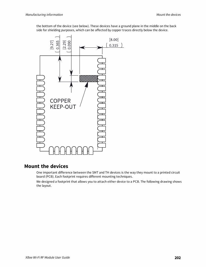
Manufacturing information Mount the devices
XBee Wi-Fi RF Module User Guide 202
the bottom of the device (see below). These devices have a ground plane in the middle on the backside for shielding purposes, which can be affected by copper traces directly below the device.
Mount the devicesOne important difference between the SMT and TH devices is the way they mount to a printed circuitboard (PCB). Each footprint requires different mounting techniques.We designed a footprint that allows you to attach either device to a PCB. The following drawing showsthe layout.
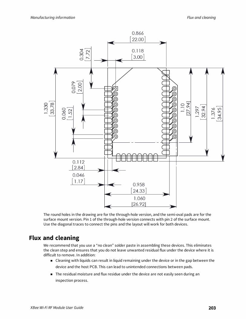
Manufacturing information Flux and cleaning
XBee Wi-Fi RF Module User Guide 203
The round holes in the drawing are for the through-hole version, and the semi-oval pads are for thesurface mount version. Pin 1 of the through-hole version connects with pin 2 of the surface mount.Use the diagonal traces to connect the pins and the layout will work for both devices.
Flux and cleaningWe recommend that you use a “no clean” solder paste in assembling these devices. This eliminatesthe clean step and ensures that you do not leave unwanted residual flux under the device where it isdifficult to remove. In addition:
n Cleaning with liquids can result in liquid remaining under the device or in the gap between thedevice and the host PCB. This can lead to unintended connections between pads.
n The residual moisture and flux residue under the device are not easily seen during aninspection process.

Manufacturing information Rework
XBee Wi-Fi RF Module User Guide 204
Note The best practice is to use a “no clean” solder paste to avoid the issues above and ensureproper module operation.
ReworkCAUTION! Any modification to the device voids the warranty coverage and certifications.
Rework should never be performed on the module itself. The module has been optimized to give thebest possible performance, and reworking the module itself will void warranty coverage andcertifications. We recognize that some customers will choose to rework and void the warranty; thefollowing information is given as a guideline in such cases to increase the chances of success duringrework, though the warranty is still voided.The module may be removed from the OEM PCB by the use of a hot air rework station, or hot plate.Care should be taken not to overheat the module. During rework, the module temperature may riseabove its internal solder melting point and care should be taken not to dislodge internal componentsfrom their intended positions.