xilinx pg178 logicore ip video to sdi tx bridge v1.0, · pdf file · 2018-01-10the...
TRANSCRIPT
LogiCORE IP Video to SDI TX Bridge v1.0
Product Guide for Vivado Design Suite
PG178 October 2, 2013
Discontinued IP

Video to SDI TX Bridge v1.0 www.xilinx.com 2PG178 October 2, 2013
Table of ContentsIP Facts
Chapter 1: OverviewFeature Summary. . . . . . . . . . . . . . . . . . . . . . . . . . . . . . . . . . . . . . . . . . . . . . . . . . . . . . . . . . . . . . . . . . 6Applications . . . . . . . . . . . . . . . . . . . . . . . . . . . . . . . . . . . . . . . . . . . . . . . . . . . . . . . . . . . . . . . . . . . . . . 6Licensing and Ordering Information . . . . . . . . . . . . . . . . . . . . . . . . . . . . . . . . . . . . . . . . . . . . . . . . . . . 7
Chapter 2: Product SpecificationPerformance. . . . . . . . . . . . . . . . . . . . . . . . . . . . . . . . . . . . . . . . . . . . . . . . . . . . . . . . . . . . . . . . . . . . . . 8Resource Utilization. . . . . . . . . . . . . . . . . . . . . . . . . . . . . . . . . . . . . . . . . . . . . . . . . . . . . . . . . . . . . . . . 8Interface Descriptions . . . . . . . . . . . . . . . . . . . . . . . . . . . . . . . . . . . . . . . . . . . . . . . . . . . . . . . . . . . . . . 9
Chapter 3: Designing with the CoreGeneral Design Guidelines . . . . . . . . . . . . . . . . . . . . . . . . . . . . . . . . . . . . . . . . . . . . . . . . . . . . . . . . . 12Clocking. . . . . . . . . . . . . . . . . . . . . . . . . . . . . . . . . . . . . . . . . . . . . . . . . . . . . . . . . . . . . . . . . . . . . . . . . 19Resets . . . . . . . . . . . . . . . . . . . . . . . . . . . . . . . . . . . . . . . . . . . . . . . . . . . . . . . . . . . . . . . . . . . . . . . . . . 19
Chapter 4: Customizing and Generating the CoreVivado Integrated Design Environment (IDE) . . . . . . . . . . . . . . . . . . . . . . . . . . . . . . . . . . . . . . . . . . 20Output Generation. . . . . . . . . . . . . . . . . . . . . . . . . . . . . . . . . . . . . . . . . . . . . . . . . . . . . . . . . . . . . . . . 21
Chapter 5: Constraining the CoreRequired Constraints . . . . . . . . . . . . . . . . . . . . . . . . . . . . . . . . . . . . . . . . . . . . . . . . . . . . . . . . . . . . . . 22Clock Frequencies . . . . . . . . . . . . . . . . . . . . . . . . . . . . . . . . . . . . . . . . . . . . . . . . . . . . . . . . . . . . . . . . 22Clock Management . . . . . . . . . . . . . . . . . . . . . . . . . . . . . . . . . . . . . . . . . . . . . . . . . . . . . . . . . . . . . . . 22Clock Placement. . . . . . . . . . . . . . . . . . . . . . . . . . . . . . . . . . . . . . . . . . . . . . . . . . . . . . . . . . . . . . . . . . 22Banking . . . . . . . . . . . . . . . . . . . . . . . . . . . . . . . . . . . . . . . . . . . . . . . . . . . . . . . . . . . . . . . . . . . . . . . . . 22Transceiver Placement . . . . . . . . . . . . . . . . . . . . . . . . . . . . . . . . . . . . . . . . . . . . . . . . . . . . . . . . . . . . 23I/O Standard and Placement. . . . . . . . . . . . . . . . . . . . . . . . . . . . . . . . . . . . . . . . . . . . . . . . . . . . . . . . 23
Send Feedback
Discontinued IP

Video to SDI TX Bridge v1.0 www.xilinx.com 3PG178 October 2, 2013
Chapter 6: Simulation
Chapter 7: Synthesis and Implementation
Chapter 8: Test BenchDirectory and File Contents. . . . . . . . . . . . . . . . . . . . . . . . . . . . . . . . . . . . . . . . . . . . . . . . . . . . . . . . . 26
Appendix A: Verification, Compliance, and InteroperabilitySimulation . . . . . . . . . . . . . . . . . . . . . . . . . . . . . . . . . . . . . . . . . . . . . . . . . . . . . . . . . . . . . . . . . . . . . . 28Hardware Testing. . . . . . . . . . . . . . . . . . . . . . . . . . . . . . . . . . . . . . . . . . . . . . . . . . . . . . . . . . . . . . . . . 28Interoperability . . . . . . . . . . . . . . . . . . . . . . . . . . . . . . . . . . . . . . . . . . . . . . . . . . . . . . . . . . . . . . . . . . 29
Appendix B: DebuggingFinding Help on Xilinx.com . . . . . . . . . . . . . . . . . . . . . . . . . . . . . . . . . . . . . . . . . . . . . . . . . . . . . . . . . 30Debug Tools . . . . . . . . . . . . . . . . . . . . . . . . . . . . . . . . . . . . . . . . . . . . . . . . . . . . . . . . . . . . . . . . . . . . . 31Hardware Debug . . . . . . . . . . . . . . . . . . . . . . . . . . . . . . . . . . . . . . . . . . . . . . . . . . . . . . . . . . . . . . . . . 32
Appendix C: Additional ResourcesXilinx Resources . . . . . . . . . . . . . . . . . . . . . . . . . . . . . . . . . . . . . . . . . . . . . . . . . . . . . . . . . . . . . . . . . . 33References . . . . . . . . . . . . . . . . . . . . . . . . . . . . . . . . . . . . . . . . . . . . . . . . . . . . . . . . . . . . . . . . . . . . . . 33Revision History . . . . . . . . . . . . . . . . . . . . . . . . . . . . . . . . . . . . . . . . . . . . . . . . . . . . . . . . . . . . . . . . . . 33Notice of Disclaimer. . . . . . . . . . . . . . . . . . . . . . . . . . . . . . . . . . . . . . . . . . . . . . . . . . . . . . . . . . . . . . . 34
Send Feedback
Discontinued IP

Video to SDI TX Bridge v1.0 www.xilinx.com 4PG178 October 2, 2013 Product Specification
IntroductionThe LogiCORE IP Video to SDI TX Bridge connects the video output of the AXI4-Stream to Video Output core to the SDI transmitter input of the SMPTE SDI core. The input is Video data with explicit synchronization signals. The output is an SDI virtual interface with one to four 10-bit data streams and embedded synchronization.
Features• Embeds synchronization signals into the
SDI data stream.
• Creates and embeds line numbers into the SDI data stream.
• Generates clock enables for SDI-SDI and 3G-SDI level B modes.
• Supports YCbCr data format at 10-bits per component.
• Supports SD-SDI, HD-SDI, 3G-SDI Level A, and 3G-SDI Level B.
• Re-orders sequential video data to parallel data in 3G Level B.
• Supports interlaced and progressive line standards.
IP Facts
LogiCORE IP Facts Table
Core SpecificsSupported Device Family(1) Zynq®-7000, Artix®-7, Virtex®-7, Kintex®-7
Supported User Interfaces N/A
Resources See Table 2-1.
Provided with CoreDesign Files Verilog Source Code
Example Design Not Provided
Test Bench Verilog
Constraints File XDC
Simulation Model Verilog Source Code
Supported S/W Driver N/A
Tested Design Flows(2)
Design EntryVivado® Design Suite
IP Integrator
Simulation For support simulators, see the Xilinx DesignTools: Release Notes Guide.
Synthesis Vivado Synthesis
SupportProvided by Xilinx @ www.xilinx.com/support
Notes: 1. For a complete list of supported devices, see Vivado IP
catalog.2. For the supported versions of the tools, see the Xilinx Design
Tools: Release Notes Guide.
Send Feedback
Discontinued IP
Video to SDI TX Bridge v1.0 www.xilinx.com 5PG178 October 2, 2013
Chapter 1
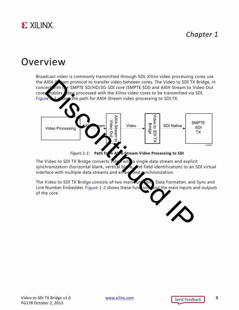
OverviewBroadcast video is commonly transmitted through SDI. Xilinx video processing cores use the AXI4-Stream protocol to transfer video between cores. The Video to SDI TX Bridge, in concert with the SMPTE SD/HD/3G-SDI core (SMPTE SDI) and AXI4-Stream to Video Out core, enables video processed with the Xilinx video cores to be transmitted via SDI. Figure 1-1 shows the path for AXI4-Stream video processing to SDI TX.
The Video to SDI TX Bridge converts video with a single data stream and explicit synchronization (horizontal blank, vertical blank, and f ield identif ication) to an SDI virtual interface with multiple data streams and embedded synchronization.
The Video to SDI TX Bridge consists of two main functions: Data Formatter, and Sync and Line Number Embedder. Figure 1-2 shows these functions and the main inputs and outputs of the core.
X-Ref Target - Figure 1-1
Figure 1-1: Path from AXI4-Stream Video Processing to SDI
Send Feedback
Discontinued IP

Video to SDI TX Bridge v1.0 www.xilinx.com 6PG178 October 2, 2013
Chapter 1: Overview
Feature SummaryThe Video to SDI TX Bridge core converts video input (consisting of parallel video data), video blanks and a video clock enable, to an SDI virtual interface data. The core is designed to interface between the AXI4-Stream to Video Output core and the SMPTE-SDI core. It can also be connected to other cores that have SDI virtual interfaces or video interfaces.
The core embeds synchronization packets into the SDI data stream. It creates and embeds line numbers into the SDI data stream. It supports SD-SDI, HD-SDI, 3G-SDI Level A, and 3G-SDI Level B. In addition, it supports YCbCr data format at 10 bits per component. For SDI-SDI and 3G-SDI level B modes, it generates the required clock enables. It automatically re-orders sequential video data to parallel data in 3G Level B. It supports interlaced and progressive line standards.
Applications• Video input with parallel, clocked, video and timing
° Video to AXI4 Stream core
° DVI
° HDMI
° Other clocked, parallel video sources
X-Ref Target - Figure 1-2
Figure 1-2: Top Level Block Diagram of Video to SDI TX Bridge
Send Feedback
Discontinued IP

Video to SDI TX Bridge v1.0 www.xilinx.com 7PG178 October 2, 2013
Chapter 1: Overview
• SDI virtual interface output
° SMPTE SDI RX
° Other SDI virtual interface sinks
Licensing and Ordering InformationThis Xilinx LogiCORE™ IP module is provided at no additional cost with the Xilinx® Vivado Design Suite under the terms of the Xilinx End User License. Information about this and other Xilinx LogiCORE IP modules is available at the Xilinx Intellectual Property page. For information about pricing and availability of other Xilinx LogiCORE IP modules and tools, contact your local Xilinx sales representative.
Send Feedback
Discontinued IP

Video to SDI TX Bridge v1.0 www.xilinx.com 8PG178 October 2, 2013
Chapter 2
Product SpecificationThis chapter includes details about the performance of this core.
PerformanceThe following sections detail the performance characteristics of the SDI RX to Video Bridge.
Maximum FrequenciesThe target frequency is 150 MHz to support 3G-SDI rates. The maximum achievable clock frequency can vary. The maximum achievable clock frequency and all resource counts can be affected by tool options, additional logic in the FPGA device, using a different version of Xilinx tools and other factors.
LatencyFor modes other than 3G-SDI Level B, the latency is f ive clock cycles as shown in Figure 3-6. For 3G-Level B, the latency is slightly more than one line as shown in Figure 3-7.
ThroughputOne pixel is output for every clock in which clock enable is asserted. Therefore the nominal throughput is the same as the clock frequency. The target throughput is 150 Mp/s to support 3G-SDI rates.
Resource UtilizationThe information presented in Table 2-1 is a guide to the resource utilization and maximum clock frequency of the Video to SDI TX Bridge core for Virtex-7, Kintex-7, Artix-7, and Zynq-7000 device families using the lowest speed grade.
The FMAX rate is for reference only since clock rate used on this core will be determined by the SDI mode. The highest SDI clock rate is 148.5 MHz, which is met in all supported
Send Feedback
Discontinued IP

Video to SDI TX Bridge v1.0 www.xilinx.com 9PG178 October 2, 2013
Chapter 2: Product Specification
families. This core does not use any dedicated I/O or CLK resources. The design was tested using Vivado Design Suite tools with default tool options for characterization data.
Interface DescriptionsThe Video to SDI TX Bridge uses industry standard control and data interfaces to connect to other system components. This section describes the various interfaces available with the core.
Common InterfaceTable 2-2 lists the common interface signals.
Video InterfaceTable 2-3 lists the video interface signals.
Table 2-1: Resource Utilization
Family LUTs FFs 36k BRAMs 18k BRAMs FMAX (MHz)
Artix-7 305 595 2 2 219
Kintex-7 305 595 2 2 312
Virtex-7 305 595 2 2 304
Zynq-7000 305 595 2 2 304
Table 2-2: Common Interface Signals
Signal Name Direction Width Description
tx_usrclk In 1 System clock.
rst In 1 System reset.
vid_ce Out 2 Video clock enable. Two identical clock enable outputs are provided for signal loading purposes.
Table 2-3: Video Interface Signals
Signal Name Direction Width Description
vid_active_video In 1 Video data enable.• 1 = active video• 0 = blanked video
vid_vblank In 1 Vertical blank video timing signal. Active High.
vid_hblank In 1 Horizontal blank video timing signal. Active High.
Send Feedback
Discontinued IP

Video to SDI TX Bridge v1.0 www.xilinx.com 10PG178 October 2, 2013
Chapter 2: Product Specification
Video Data
The 20-bit video data output, vid_data, carries two 10-bit components and is packed with the chroma data in the MSBs and the luma data in the LSBs, as shown in Figure 2-1.
SDI Virtual InterfaceTable 2-4 lists the SDI virtual interface signals.
vid_field_id In 1 Field identif ication bit. • 0 = f ield 1• 1 = f ield 2
vid_data In 20 Parallel video data. See Video Data.
X-Ref Target - Figure 2-1
Figure 2-1: Video Data Format
Table 2-4: SDI Interface Signals
Signal Name Direction Width Description
tx_video_a_y Out 10 This is the data stream A Y input. The data on this port depends on the SDI mode:• SD-SDI: Multiplexed Y/C data stream.• HD-SDI: Y component.• 3G-SDI level A: Data stream 1.• Dual link HD-SDI or 3G-SDI level B-DL: Data stream 1 of link
A.
tx_video_a_c Out 10 This is the data stream A C input. The data on this port depends on the SDI mode.• SD-SDI: Unused.• HD-SDI: Interleaved CB and CR components.• 3G-SDI level A: Data stream 2.• Dual link HD-SDI or 3G-SDI level B-DL: Data stream 2 of link
A.
tx_video_b_y Out 10 This is the data stream B Y input. The data stream on this port depends on the SDI mode:• 3G-SDI level B-DL: Data stream 1 of link B.For other SDI modes, this input port is unused.
tx_video_b_c Out 10 This is the data stream B C input: The data stream on this port depends on the SDI mode.• 3G-SDI level B-DL: Data stream 2 of link BFor other SDI modes, this input port is unused.
tx_eav Indicates the presence of the XYZ character with the H bit high.
Table 2-3: Video Interface Signals (Cont’d)
Signal Name Direction Width Description
Send Feedback
Discontinued IP
Video to SDI TX Bridge v1.0 www.xilinx.com 11PG178 October 2, 2013
Chapter 2: Product Specification
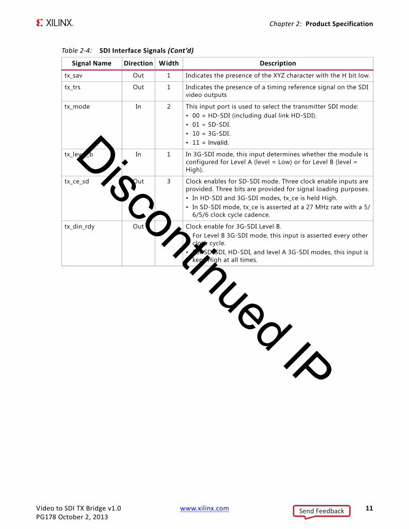
tx_sav Out 1 Indicates the presence of the XYZ character with the H bit low.
tx_trs Out 1 Indicates the presence of a timing reference signal on the SDI video outputs
tx_mode In 2 This input port is used to select the transmitter SDI mode:• 00 = HD-SDI (including dual link HD-SDI).• 01 = SD-SDI.• 10 = 3G-SDI.• 11 = Invalid.
tx_level_b In 1 In 3G-SDI mode, this input determines whether the module is configured for Level A (level = Low) or for Level B (level = High).
tx_ce_sd Out 3 Clock enables for SD-SDI mode. Three clock enable inputs are provided. Three bits are provided for signal loading purposes.• In HD-SDI and 3G-SDI modes, tx_ce is held High. • In SD-SDI mode, tx_ce is asserted at a 27 MHz rate with a 5/
6/5/6 clock cycle cadence.
tx_din_rdy Out 1 Clock enable for 3G-SDI Level B. • For Level B 3G-SDI mode, this input is asserted every other
clock cycle. • For SD-SDI, HD-SDI, and level A 3G-SDI modes, this input is
kept High at all times.
Table 2-4: SDI Interface Signals (Cont’d)
Signal Name Direction Width Description
Send Feedback
Discontinued IP
Video to SDI TX Bridge v1.0 www.xilinx.com 12PG178 October 2, 2013
Chapter 3
Designing with the CoreThis chapter includes guidelines and additional information to facilitate designing with the core.
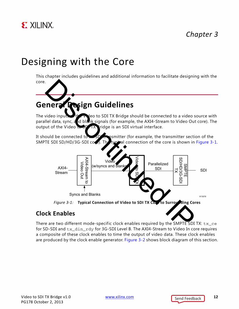
General Design GuidelinesThe video inputs of the Video to SDI TX Bridge should be connected to a video source with parallel data, sync, and blank signals (for example, the AXI4-Stream to Video Out core). The output of the Video to SDI TX Bridge is an SDI virtual interface.
It should be connected to an SDI transmitter (for example, the transmitter section of the SMPTE SDI SD/HD/3G-SDI core). The typical connection of the core is shown in Figure 3-1.
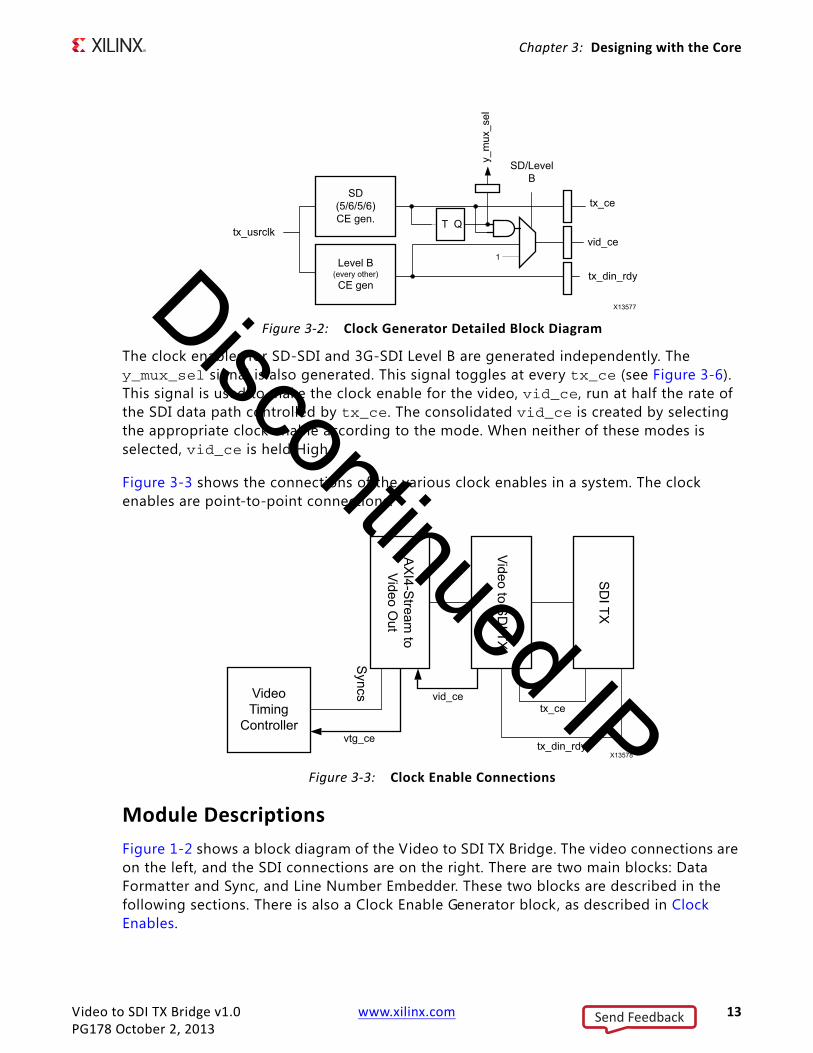
Clock EnablesThere are two different mode-specif ic clock enables required by the SMPTE SDI TX: tx_ce for SD-SDI and tx_din_rdy for 3G-SDI Level B. The AXI4-Stream to Video In core requires a composite of these clock enables to time the output of video data. These clock enables are produced by the clock enable generator. Figure 3-2 shows block diagram of this section.
X-Ref Target - Figure 3-1
Figure 3-1: Typical Connection of Video to SDI TX Core to Surrounding Cores
Send Feedback
Discontinued IP
Video to SDI TX Bridge v1.0 www.xilinx.com 13PG178 October 2, 2013
Chapter 3: Designing with the Core
The clock enables for SD-SDI and 3G-SDI Level B are generated independently. The y_mux_sel signal is also generated. This signal toggles at every tx_ce (see Figure 3-6). This signal is used to make the clock enable for the video, vid_ce, run at half the rate of the SDI data path controlled by tx_ce. The consolidated vid_ce is created by selecting the appropriate clock enable according to the mode. When neither of these modes is selected, vid_ce is held High.
Figure 3-3 shows the connections of the various clock enables in a system. The clock enables are point-to-point connections.
Module DescriptionsFigure 1-2 shows a block diagram of the Video to SDI TX Bridge. The video connections are on the left, and the SDI connections are on the right. There are two main blocks: Data Formatter and Sync, and Line Number Embedder. These two blocks are described in the following sections. There is also a Clock Enable Generator block, as described in Clock Enables.
X-Ref Target - Figure 3-2
Figure 3-2: Clock Generator Detailed Block Diagram
X-Ref Target - Figure 3-3
Figure 3-3: Clock Enable Connections
Send Feedback
Discontinued IP

Video to SDI TX Bridge v1.0 www.xilinx.com 14PG178 October 2, 2013
Chapter 3: Designing with the Core
Data Formatter
The Data Formatter splits the single video input data stream into as many as four SDI data streams, as shown in Figure 3-4.
The video data is 10 bits wide, carrying the Y component in 10 bits and the Cb/Cr component in the other 10 bits. The output format depends on the SDI mode. In HD-SDI and 3G-SDI Level A, the output is 20 bits wide, allowing the video to be passed virtually straight through. However, in SD-SDI mode, the output is only 10 bits wide, alternating Y words with Cb/Cr words. Thus the video is reformatted to 10-bits wide at double the rate. In 3G-SDI Level B mode, the output data is 40 bits wide. The format of the data is two lines in parallel, each 20 bits wide. The data for one line is carried on tx_ds1a and tx_ds2a, and data for the other is carried on tx_ds1b and tx_ds2b. Data for these two lines is captured serially in FIFOs so that it can be output with two lines in parallel. Figure 3-5 shows a block diagram of the Data Formatter.
Figure 3-6 is a timing diagram of SD-SDI mapping from 20 bits of video_data to 10 bits of SD-SDI. There is an internally generated enable, y_mux_sel, that is created internal to the core, but not shown in the block diagram.
X-Ref Target - Figure 3-4
Figure 3-4: Data Formatter I/O
X-Ref Target - Figure 3-5
Figure 3-5: Data Formatter Detailed Block Diagram
Send Feedback
Discontinued IP

Video to SDI TX Bridge v1.0 www.xilinx.com 15PG178 October 2, 2013
Chapter 3: Designing with the Core
Figure 3-7 is a timing diagram of 3G-SDI Level B mapping from lines received sequentially, one line at a time, to two lines transmitted in parallel. Note that Link B only has to store slightly more than half of a line because it starts outputting just after data starts coming in on Link B. Because the data comes in twice as fast as it goes out, half a line must be stored up by the time the Link B line input is f inished. Alternatively, the Link A FIFO must store slightly more than an entire line before the f irst pixels are read from it. This is why the Link B FIFO is only half as deep as the Link A FIFO.
Sync and Line Number Embedder
The Sync and Line Number Embedder creates line numbers and timing reference symbol (TRS) packets from the video input and embeds these into the video stream for SDI. The SDI data stream requires end of active video (EAV) and start of active video (SAV) timing signals embedded as TRS packets. In addition, a field identif ier bit is also included in each TRS. For HD-SDI and 3G-SDI, the EAV packet includes a line number. The TRS packets are embedded in each data stream of SDI. Figure 3-8 shows the inputs and output of the Sync and Line Number Embedder.
X-Ref Target - Figure 3-6
Figure 3-6: Timing Diagram for SD-SDI Data Format Reformatting
X-Ref Target - Figure 3-7
Figure 3-7: Timing Diagram of 3G-SDI Level B Data Reformatting
Send Feedback
Discontinued IP

Video to SDI TX Bridge v1.0 www.xilinx.com 16PG178 October 2, 2013
Chapter 3: Designing with the Core
Figure 3-9 shows a block diagram of the Sync and Line Number Embedder. The Line Counter counts lines based on the video blanking signals. Likewise, the TRS generator creates TRS packets of the appropriate type based on the video blanks. These packets are inserted into the video stream at the appropriate time, and line numbers are inserted in EAV packets under control of the TRS generator.
X-Ref Target - Figure 3-8
Figure 3-8: Sync and Line Number Embedder I/O
X-Ref Target - Figure 3-9
Figure 3-9: Sync and Line Number Embedder Block Diagram
Send Feedback
Discontinued IP

Video to SDI TX Bridge v1.0 www.xilinx.com 17PG178 October 2, 2013
Chapter 3: Designing with the Core
TRS packets are placed in the horizontal blanking periods. The SAV packet immediately precedes active video. Because of this, active video data must be suff iciently delayed so that the packet can be embedded after the blank is received and before the start of active video. This is shown in Figure 3-10.
EAV immediately follows active video, as shown in Figure 3-11. The two-line number words immediately follow the XYZ word.
X-Ref Target - Figure 3-10
Figure 3-10: Timing Diagram for SAV
Send Feedback
Discontinued IP

Video to SDI TX Bridge v1.0 www.xilinx.com 18PG178 October 2, 2013
Chapter 3: Designing with the Core
Clock Enable GeneratorThe Clock Enable Generator produces the clock enables required for the SDI TX core and the AXI4-Stream to Video out core. It also produces output_ce, a clock enable that is used internally. The cadence of these clock enables depends on the mode. Figure 3-12 details the Clock Enable Generator.
X-Ref Target - Figure 3-11
Figure 3-11: Timing Diagram for EAV
Send Feedback
Discontinued IP

Video to SDI TX Bridge v1.0 www.xilinx.com 19PG178 October 2, 2013
Chapter 3: Designing with the Core
ClockingThe Video to SDI TX Bridge core uses one clock, vid_io_in_clk . This clock is the same as tx_usrclk on the SDI SD/HD/3G-SDI core, clk on the Video Timing Controller, and the vid_io_out_clk on the AXI4-Stream to Video Out core. There are three clock enables: one input and two outputs. The functionality and connections for these are described in Clock Enables.
ResetsAn external reset, rst, is provided to reset the entire core. This reset is synchronous with the clock.
X-Ref Target - Figure 3-12
Figure 3-12: Clock Enable Generator
Send Feedback
Discontinued IP

Video to SDI TX Bridge v1.0 www.xilinx.com 20PG178 October 2, 2013
Chapter 4
Customizing and Generating the CoreThis chapter includes information about using Xilinx tools to customize and generate the core in the Vivado® Design Suite.
Vivado Integrated Design Environment (IDE)You can customize the IP for use in your design by specifying values for the various parameters associated with the IP core using the following steps:
1. Select the IP from the IP catalog.
2. Double-click the selected IP or select the Customize IP command from the toolbar or popup menu.
For details, see the sections, “Working with IP” and “Customizing IP for the Design” in the Vivado Design Suite User Guide: Designing with IP (UG896) [Ref 6] and the “Working with the Vivado IDE” section in the Vivado Design Suite User Guide: Getting Started (UG910) [Ref 7].
Note: Figures in this chapter are illustrations of the Vivado IDE. This layout might vary from the current version.
Send Feedback
Discontinued IP

Video to SDI TX Bridge v1.0 www.xilinx.com 21PG178 October 2, 2013
Chapter 4: Customizing and Generating the Core
The Vivado IDE displays a representation of the IP symbol on the left side, and the parameter assignments on the right side. Because the SDI mode changes are handled dynamically, there is only one parameter: Component Name. The component name is used as the base name of output files generated for the module. Names must begin with a letter and must be composed from characters: a to z, 0 to 9 and "_".
Output GenerationFor complete instructions and standard file output, see “Generating IP Output Products” in the Vivado Design Suite User Guide: Designing with IP (UG896) [Ref 3].
X-Ref Target - Figure 4-1
Figure 4-1: Video to SDI TX Bridge IDE
Send Feedback
Discontinued IP

Video to SDI TX Bridge v1.0 www.xilinx.com 22PG178 October 2, 2013
Chapter 5
Constraining the CoreThis chapter contains information about constraining the core in the Vivado® Design Suite environment.
Required ConstraintsThe only constraint required is a clock frequency constraint for the video clock, tx_usrclk . An example of this constraint is generated automatically for 150 MHz when the core is compiled out of context:
create_clock -add -name tx_usrclk -period 6.666 [get_ports tx_usrclk]
Clock FrequenciesThe pixel clock frequency is the required frequency for this core. See Maximum Frequencies in Chapter 2.
Clock ManagementThere are no specific clock management constraints required for this core.
Clock PlacementThere are no specific clock placement requirements for this core.
BankingThere are no specific banking rules for this core.
Send Feedback
Discontinued IP
Video to SDI TX Bridge v1.0 www.xilinx.com 23PG178 October 2, 2013
Chapter 5: Constraining the Core
Transceiver PlacementThere are no transceiver placement requirements for this core.
I/O Standard and PlacementThere are no specific I/O standards and placement requirements for this core.
Send Feedback
Discontinued IP

Video to SDI TX Bridge v1.0 www.xilinx.com 24PG178 October 2, 2013
Chapter 6
SimulationThis chapter contains information about simulating in the Vivado® Design Suite environment. For details, see the Vivado Design Suite User Guide: Logic Simulation (UG900) [Ref 1].
Send Feedback
Discontinued IP
Video to SDI TX Bridge v1.0 www.xilinx.com 25PG178 October 2, 2013
Chapter 7
Synthesis and ImplementationThis chapter contains information about synthesis and implementation in the Vivado® Design Suite environment.
For details about synthesis and implementation, see “Synthesizing IP” and “Implementing IP” in the Vivado Design Suite User Guide: Designing with IP (UG896) [Ref 3].
Send Feedback
Discontinued IP

Video to SDI TX Bridge v1.0 www.xilinx.com 26PG178 October 2, 2013
Chapter 8
Test BenchThis chapter contains information about the provided test bench in the Vivado® Design Suite environment. The test bench provided enables you to observe core behavior in an example scenario. You can observe various signals within the design to gain detailed insight into its operation.
There are no stimulus or results f iles, but the test bench module generates input and expected data, and performs the comparison of output data to the expected data. Several small frames of parallel video are generated with different timing parameters and applied to the core. Video data is generated by the test bench and input to the Video to SDI TX Bridge as the device under test. The core outputs an SDI virtual interface that is sent to the SDI RX to Video Bridge for conversion from SDI virtual interface back to video with syncs. When the output has stabilized, the video data output is compared to the expected parallel video data.
Directory and File ContentsThe demonstration test bench generates tb_<IP_instance_name>.v in the output directory. Other test modules include:
• video_gen.v
• video_test.v
• video_check.v
The RX Bridge Behavioral Model includes:
• rx_bridge/v_sdi_rx_vid_bridge_v1_0_top.v
• rx_bridge/v_sdi_rx_vid_bridge_v1_0_ce_gen.v
• rx_bridge/v_sdi_rx_vid_bridge_v1_0_fifo.v
• rx_bridge/v_sdi_rx_vid_bridge_v1_0_formatter.v
• rx_bridge/v_sdi_rx_vid_bridge_v1_0_sync_extract.v
• rx_bridge/v_sdi_rx_vid_bridge_v1_0_trs_decode.v
Send Feedback
Discontinued IP

Video to SDI TX Bridge v1.0 www.xilinx.com 27PG178 October 2, 2013
Chapter 8: Test Bench
Table 8-1 shows the test bench structure.
X-Ref Target - Figure 8-1
Figure 8-1: Test Bench Structure
Send Feedback
Discontinued IP

Video to SDI TX Bridge v1.0 www.xilinx.com 28PG178 October 2, 2013
Appendix A
Verification, Compliance, and Interoperability
This appendix includes information about how the IP was tested for compliance with the protocol to which it was designed.
SimulationThe test bench used to test the SDI RX to Video Bridge included the following:
• Testing with multiple frames of data with many different frame sizes.
• Testing for operation in SD-SDI, HD-SDI, 3G-SDI Level A, and 3G-SDI Level B.
• Testing of locking and re-locking after input interruption and format changes.
Simulation was done on a pass-through video system consisting of the Video to SDI TX Bridge in a system with the SDI RX to Video core.
Hardware TestingThe Video to SDI TX Bridge has been validated in hardware using a complete pass-through design: SMPTE SDI RX → SDI RX to Video Bridge → Video to SDI TX Bridge → SMPTE SDI TX. The test used an external SDI video source as an input and an SDI video analyzer to verify the output. Output re-synchronization was tested by removing and re-applying the video source multiple times, and by repeatedly changing line standards and modes.
Send Feedback
Discontinued IP

Video to SDI TX Bridge v1.0 www.xilinx.com 29PG178 October 2, 2013
Appendix A: Verification, Compliance, and Interoperability
InteroperabilityThe video input is compatible with devices that accept data in the format provided: component video data, syncs, blanks, and data valid. Examples include the AXI4-Stream to Video core and digital video PHYs, such as DVI and HDMI. The SDI output interface is compatible with devices that input SDI virtual interface in the manner of the SMPTE SDI core TX.
Send Feedback
Discontinued IP

Video to SDI TX Bridge v1.0 www.xilinx.com 30PG178 October 2, 2013
Appendix B
DebuggingThis appendix includes details about resources available on the Xilinx Support website and debugging tools.
Finding Help on Xilinx.comTo help in the design and debug process when using the Video to SDI TX Bridge, the Xilinx Support web page (www.xilinx.com/support) contains key resources such as product documentation, release notes, answer records, information about known issues, and links for obtaining further product support.
DocumentationThis product guide is the main document associated with the Video to SDI TX Bridge. This guide, along with documentation related to all products that aid in the design process, can be found on the Xilinx Support web page (www.xilinx.com/support) or by using the Xilinx Documentation Navigator.
Download the Xilinx Documentation Navigator from the Design Tools tab on the Downloads page (www.xilinx.com/download). For more information about this tool and the features available, open the online help after installation.
Answer RecordsAnswer Records include information about commonly encountered problems, helpful information on how to resolve these problems, and any known issues with a Xilinx product. Answer Records are created and maintained daily ensuring that users have access to the most accurate information available.
Answer Records for this core can also be located by using the Search Support box on the main Xilinx support web page. To maximize your search results, use proper keywords such as
• Product name
• Tool message(s)
Send Feedback
Discontinued IP

Video to SDI TX Bridge v1.0 www.xilinx.com 31PG178 October 2, 2013
Appendix B: Debugging
• Summary of the issue encountered
A filter search is available after results are returned to further target the results.
Master Answer Record for the Video to SDI TX Bridge Core
AR: 54544
Contacting Technical SupportXilinx provides technical support at www.xilinx.com/support for this LogiCORE™ IP product when used as described in the product documentation. Xilinx cannot guarantee timing, functionality, or support of product if implemented in devices that are not defined in the documentation, if customized beyond that allowed in the product documentation, or if changes are made to any section of the design labeled DO NOT MODIFY.
To contact Xilinx Technical Support:
1. Navigate to www.xilinx.com/support.
2. Open a WebCase by selecting the WebCase link located under Additional Resources.
When opening a WebCase, include:
• Target FPGA including package and speed grade.
• All applicable Xilinx Design Tools and simulator software versions.
• Additional f iles based on the specif ic issue might also be required. See the relevant sections in this debug guide for guidelines about which f ile(s) to include with the WebCase.
Note: Access to WebCase is not available in all cases. Login to the WebCase tool to see your specif ic support options.
Debug ToolsThere are many tools available to address Video to SDI TX Bridge design issues. It is important to know which tools are useful for debugging various situations.
Vivado Lab ToolsVivado® lab tools insert logic analyzer and virtual I/O cores directly into your design. Vivado lab tools allow you to set trigger conditions to capture application and integrated block port signals in hardware. Captured signals can then be analyzed. This feature represents the functionality in the Vivado IDE that is used for logic debugging and validation of a design running in Xilinx devices in hardware.
Send Feedback
Discontinued IP
Video to SDI TX Bridge v1.0 www.xilinx.com 32PG178 October 2, 2013
Appendix B: Debugging
The Vivado lab tools logic analyzer is used to interact with the logic debug LogiCORE IP cores, including:
• ILA 2.0 (and later versions)
• VIO 2.0 (and later versions)
See Vivado Design Suite User Guide: Programming and Debugging (UG908) [Ref 4].
Hardware DebugThis section provides debug steps for common hardware issues. The Vivado lab tools are a valuable resource to use in hardware debug. The signal names mentioned in the following individual sections can be probed using the Vivado lab tools for debugging the specific problems.
General ChecksEnsure that all the timing constraints for the core were properly incorporated from the example design and that all constraints were met during implementation.
• Does it work in post-place and route timing simulation? If problems are seen in hardware but not in timing simulation, this could indicate a PCB issue. Ensure that all clock sources are active and clean.
• If using MMCMs in the design, ensure that all MMCMs have obtained lock by monitoring the LOCKED port.
• Check that the clock is present with the expected frequency.
• Check that resets have been de-asserted.
• Check that clock enable inputs are asserting.
Send Feedback
Discontinued IP

Video to SDI TX Bridge v1.0 www.xilinx.com 33PG178 October 2, 2013
Appendix C
Additional Resources
Xilinx ResourcesFor support resources such as Answers, Documentation, Downloads, and Forums, see the Xilinx Support website at:
www.xilinx.com/support.
For a glossary of technical terms used in Xilinx documentation, see:
www.xilinx.com/company/terms.htm.
ReferencesThese documents provide supplemental material useful with this product guide:
1. Vivado Design Suite User Guide: Logic Simulation (UG900)
2. Vivado Design Suite User Guide: Implementation (UG904)
3. Vivado Design Suite User Guide: Designing with IP (UG896)
4. Vivado Design Suite User Guide: Programming and Debugging (UG908)
5. Vivado Design Suite User Guide: Getting Started (UG910)
Revision HistoryThe following table shows the revision history for this document.
Date Version Revision
10/02/2013 1.0 Initial Xilinx release.
Send Feedback
Discontinued IP
Video to SDI TX Bridge v1.0 www.xilinx.com 34PG178 October 2, 2013
Appendix C: Additional Resources
Notice of DisclaimerThe information disclosed to you hereunder (the “Materials”) is provided solely for the selection and use of Xilinx products. To the maximum extent permitted by applicable law: (1) Materials are made available “AS IS” and with all faults, Xilinx hereby DISCLAIMS ALL WARRANTIES AND CONDITIONS, EXPRESS, IMPLIED, OR STATUTORY, INCLUDING BUT NOT LIMITED TO WARRANTIES OF MERCHANTABILITY, NON-INFRINGEMENT, OR FITNESS FOR ANY PARTICULAR PURPOSE; and (2) Xilinx shall not be liable (whether in contract or tort, including negligence, or under any other theory of liability) for any loss or damage of any kind or nature related to, arising under, or in connection with, the Materials (including your use of the Materials), including for any direct, indirect, special, incidental, or consequential loss or damage (including loss of data, profits, goodwill, or any type of loss or damage suffered as a result of any action brought by a third party) even if such damage or loss was reasonably foreseeable or Xilinx had been advised of the possibility of the same. Xilinx assumes no obligation to correct any errors contained in the Materials or to notify you of updates to the Materials or to product specifications. You may not reproduce, modify, distribute, or publicly display the Materials without prior written consent. Certain products are subject to the terms and conditions of the Limited Warranties which can be viewed at http://www.xilinx.com/warranty.htm; IP cores may be subject to warranty and support terms contained in a license issued to you by Xilinx. Xilinx products are not designed or intended to be fail-safe or for use in any application requiring fail-safe performance; you assume sole risk and liability for use of Xilinx products in Critical Applications: http://www.xilinx.com/warranty.htm#critapps.© Copyright 2013 Xilinx, Inc. Xilinx, the Xilinx logo, Artix, ISE, Kintex, Spartan, Virtex, Vivado, Zynq, and other designated brands included herein are trademarks of Xilinx in the United States and other countries. All other trademarks are the property of their respective owners.
Send Feedback
Discontinued IP