xilinx ug182, spi-4.2 lite v5.1 (v6.0), getting started guide · chapter 3: quick start example...
TRANSCRIPT
LogiCORE™ IP SPI-4.2 Lite v5.2
Getting Started Guide
UG182 April 19, 2010
Discontinued IP

SPI-4.2 Lite v5.2 Getting Started Guide www.xilinx.com UG182 April 19, 2010
Xilinx is providing this product documentation, hereinafter “Information,” to you “AS IS” with no warranty of any kind, express or implied. Xilinx makes no representation that the Information, or any particular implementation thereof, is free from any claims of infringement. You are responsible for obtaining any rights you may require for any implementation based on the Information. All specifications are subject to change without notice.
XILINX EXPRESSLY DISCLAIMS ANY WARRANTY WHATSOEVER WITH RESPECT TO THE ADEQUACY OF THE INFORMATION OR ANY IMPLEMENTATION BASED THEREON, INCLUDING BUT NOT LIMITED TO ANY WARRANTIES OR REPRESENTATIONS THAT THIS IMPLEMENTATION IS FREE FROM CLAIMS OF INFRINGEMENT AND ANY IMPLIED WARRANTIES OF MERCHANTABILITY OR FITNESS FOR A PARTICULAR PURPOSE.
Except as stated herein, none of the Information may be copied, reproduced, distributed, republished, downloaded, displayed, posted, or transmitted in any form or by any means including, but not limited to, electronic, mechanical, photocopying, recording, or otherwise, without the prior written consent of Xilinx.
© 2005-2010 Xilinx, Inc. XILINX, the Xilinx logo, Virtex, Spartan, ISE, and other designated brands included herein are trademarks of Xilinx in the United States and other countries. All other trademarks are the property of their respective owners.
Discontinued IP

UG182 April 19, 2010 www.xilinx.com SPI-4.2 Lite v5.2 Getting Started Guide
Revision HistoryThe following table shows the revision history for this document.
Date Version Revision
8/31/05 1.1 Initial Xilinx release.
01/18/06 1.2 Updated release version number, Xilinx tool version, and release date.
07/13/06 2.0 Updated version number, ISE support to v8.2i, release date
02/15/07 3.0 Updated version number, ISE support to v9.1i, added support for Spartan-3A
4/02/07 3.1 Added support for Spartan-3A DSP devices.
6/27/08 4.0 Added information for using VCS to simulate the example design, added vcs simulation signals and descriptions.
4/24/09 4.4 Updated core to v4.4 and ISE to v11.1.
6/24/09 5.1 Updated core to v5.1, ISE to v11.2, and added support for Virtex-6 and Spartan-6 devices.
4/19/10 6.0 Updated core to v5.2 and ISE to v12.1.
Discontinued IP
SPI-4.2 Lite v5.2 Getting Started Guide www.xilinx.com UG182 April 19, 2010
Discontinued IP

SPI-4.2 Lite v5.2 Getting Started Guide www.xilinx.com 5UG182 April 19, 2010
Schedule of Tables . . . . . . . . . . . . . . . . . . . . . . . . . . . . . . . . . . . . . . . . . . . . . . . . . . . . . . . . . . . 7
Preface: About This GuideContents . . . . . . . . . . . . . . . . . . . . . . . . . . . . . . . . . . . . . . . . . . . . . . . . . . . . . . . . . . . . . . . . . . . . . 9Additional Resources . . . . . . . . . . . . . . . . . . . . . . . . . . . . . . . . . . . . . . . . . . . . . . . . . . . . . . . 10Conventions . . . . . . . . . . . . . . . . . . . . . . . . . . . . . . . . . . . . . . . . . . . . . . . . . . . . . . . . . . . . . . . . 11
Typographical . . . . . . . . . . . . . . . . . . . . . . . . . . . . . . . . . . . . . . . . . . . . . . . . . . . . . . . . . . . . 11Online Document . . . . . . . . . . . . . . . . . . . . . . . . . . . . . . . . . . . . . . . . . . . . . . . . . . . . . . . . . 12
Chapter 1: IntroductionAbout the Core . . . . . . . . . . . . . . . . . . . . . . . . . . . . . . . . . . . . . . . . . . . . . . . . . . . . . . . . . . . . . . 13System Requirements . . . . . . . . . . . . . . . . . . . . . . . . . . . . . . . . . . . . . . . . . . . . . . . . . . . . . . . 13Recommended Design Experience . . . . . . . . . . . . . . . . . . . . . . . . . . . . . . . . . . . . . . . . . . . 14Additional Core Resources . . . . . . . . . . . . . . . . . . . . . . . . . . . . . . . . . . . . . . . . . . . . . . . . . . 14Technical Support. . . . . . . . . . . . . . . . . . . . . . . . . . . . . . . . . . . . . . . . . . . . . . . . . . . . . . . . . . . 14Feedback. . . . . . . . . . . . . . . . . . . . . . . . . . . . . . . . . . . . . . . . . . . . . . . . . . . . . . . . . . . . . . . . . . . . 14
Core . . . . . . . . . . . . . . . . . . . . . . . . . . . . . . . . . . . . . . . . . . . . . . . . . . . . . . . . . . . . . . . . . . . . 14Document . . . . . . . . . . . . . . . . . . . . . . . . . . . . . . . . . . . . . . . . . . . . . . . . . . . . . . . . . . . . . . . 15
Chapter 2: Licensing the CoreBefore you Begin . . . . . . . . . . . . . . . . . . . . . . . . . . . . . . . . . . . . . . . . . . . . . . . . . . . . . . . . . . . . 17License Options . . . . . . . . . . . . . . . . . . . . . . . . . . . . . . . . . . . . . . . . . . . . . . . . . . . . . . . . . . . . . 17
Simulation Only . . . . . . . . . . . . . . . . . . . . . . . . . . . . . . . . . . . . . . . . . . . . . . . . . . . . . . . . . . 17Full System Hardware Evaluation . . . . . . . . . . . . . . . . . . . . . . . . . . . . . . . . . . . . . . . . . . 17Full . . . . . . . . . . . . . . . . . . . . . . . . . . . . . . . . . . . . . . . . . . . . . . . . . . . . . . . . . . . . . . . . . . . . . 18
Obtaining Your License Key. . . . . . . . . . . . . . . . . . . . . . . . . . . . . . . . . . . . . . . . . . . . . . . . . 18Simulation License . . . . . . . . . . . . . . . . . . . . . . . . . . . . . . . . . . . . . . . . . . . . . . . . . . . . . . . . 18Full System Hardware Evaluation License . . . . . . . . . . . . . . . . . . . . . . . . . . . . . . . . . . . 18Full License . . . . . . . . . . . . . . . . . . . . . . . . . . . . . . . . . . . . . . . . . . . . . . . . . . . . . . . . . . . . . . 18
Installing Your License File . . . . . . . . . . . . . . . . . . . . . . . . . . . . . . . . . . . . . . . . . . . . . . . . . 18
Chapter 3: Quick Start Example DesignOverview . . . . . . . . . . . . . . . . . . . . . . . . . . . . . . . . . . . . . . . . . . . . . . . . . . . . . . . . . . . . . . . . . . . 19Generating the Core . . . . . . . . . . . . . . . . . . . . . . . . . . . . . . . . . . . . . . . . . . . . . . . . . . . . . . . . . 19Implementing the Example Design . . . . . . . . . . . . . . . . . . . . . . . . . . . . . . . . . . . . . . . . . . 21Running the Simulation . . . . . . . . . . . . . . . . . . . . . . . . . . . . . . . . . . . . . . . . . . . . . . . . . . . . . 21
Setting up for Simulation . . . . . . . . . . . . . . . . . . . . . . . . . . . . . . . . . . . . . . . . . . . . . . . . . . 21Functional Simulation . . . . . . . . . . . . . . . . . . . . . . . . . . . . . . . . . . . . . . . . . . . . . . . . . . . . . 21Timing Simulation . . . . . . . . . . . . . . . . . . . . . . . . . . . . . . . . . . . . . . . . . . . . . . . . . . . . . . . . 22
Table of Contents
Discontinued IP
6 www.xilinx.com SPI-4.2 Lite v5.2 Getting Started GuideUG182 April 19, 2010
Chapter 4: Detailed Example DesignDirectory Structure . . . . . . . . . . . . . . . . . . . . . . . . . . . . . . . . . . . . . . . . . . . . . . . . . . . . . . . . . . 25Directory and File Contents . . . . . . . . . . . . . . . . . . . . . . . . . . . . . . . . . . . . . . . . . . . . . . . . . 26
<project directory> . . . . . . . . . . . . . . . . . . . . . . . . . . . . . . . . . . . . . . . . . . . . . . . . . . . . . . . 26<project directory>/<component name> . . . . . . . . . . . . . . . . . . . . . . . . . . . . . . . . . . . . 26<component name>/example design . . . . . . . . . . . . . . . . . . . . . . . . . . . . . . . . . . . . . . . . 27<component name>/doc . . . . . . . . . . . . . . . . . . . . . . . . . . . . . . . . . . . . . . . . . . . . . . . . . . 27<component name>/implement . . . . . . . . . . . . . . . . . . . . . . . . . . . . . . . . . . . . . . . . . . . . 28implement/results . . . . . . . . . . . . . . . . . . . . . . . . . . . . . . . . . . . . . . . . . . . . . . . . . . . . . . . . 28<component name>/simulation . . . . . . . . . . . . . . . . . . . . . . . . . . . . . . . . . . . . . . . . . . . . 29simulation/functional . . . . . . . . . . . . . . . . . . . . . . . . . . . . . . . . . . . . . . . . . . . . . . . . . . . . . 29simulation/timing . . . . . . . . . . . . . . . . . . . . . . . . . . . . . . . . . . . . . . . . . . . . . . . . . . . . . . . . 31
Implementation and Simulation Scripts . . . . . . . . . . . . . . . . . . . . . . . . . . . . . . . . . . . . . 31Simulation Script Details. . . . . . . . . . . . . . . . . . . . . . . . . . . . . . . . . . . . . . . . . . . . . . . . . . . 32
Example Design Configuration . . . . . . . . . . . . . . . . . . . . . . . . . . . . . . . . . . . . . . . . . . . . . . 32Loopback Module . . . . . . . . . . . . . . . . . . . . . . . . . . . . . . . . . . . . . . . . . . . . . . . . . . . . . . . . 33Basic Loopback Operation . . . . . . . . . . . . . . . . . . . . . . . . . . . . . . . . . . . . . . . . . . . . . . . . . 33
Demonstration Test Bench . . . . . . . . . . . . . . . . . . . . . . . . . . . . . . . . . . . . . . . . . . . . . . . . . . 34Clock Generator . . . . . . . . . . . . . . . . . . . . . . . . . . . . . . . . . . . . . . . . . . . . . . . . . . . . . . . . . . 35Startup Module. . . . . . . . . . . . . . . . . . . . . . . . . . . . . . . . . . . . . . . . . . . . . . . . . . . . . . . . . . . 36Stimulus Module . . . . . . . . . . . . . . . . . . . . . . . . . . . . . . . . . . . . . . . . . . . . . . . . . . . . . . . . . 37Procedures Module . . . . . . . . . . . . . . . . . . . . . . . . . . . . . . . . . . . . . . . . . . . . . . . . . . . . . . . 37Data Monitor . . . . . . . . . . . . . . . . . . . . . . . . . . . . . . . . . . . . . . . . . . . . . . . . . . . . . . . . . . . . . 38Status Monitor . . . . . . . . . . . . . . . . . . . . . . . . . . . . . . . . . . . . . . . . . . . . . . . . . . . . . . . . . . . 38Customizing the Demonstration Test Bench . . . . . . . . . . . . . . . . . . . . . . . . . . . . . . . . . . 39Testcase Package . . . . . . . . . . . . . . . . . . . . . . . . . . . . . . . . . . . . . . . . . . . . . . . . . . . . . . . . . 39Testcase Module . . . . . . . . . . . . . . . . . . . . . . . . . . . . . . . . . . . . . . . . . . . . . . . . . . . . . . . . . . 41Calendar Sequence Files (Sink and Source) . . . . . . . . . . . . . . . . . . . . . . . . . . . . . . . . . . . 43
Appendix A: VHDL DetailsProcedures Module . . . . . . . . . . . . . . . . . . . . . . . . . . . . . . . . . . . . . . . . . . . . . . . . . . . . . . . . . 45
Appendix B: Verilog DetailsProcedures Module . . . . . . . . . . . . . . . . . . . . . . . . . . . . . . . . . . . . . . . . . . . . . . . . . . . . . . . . . 49Random Testcase Sample Code. . . . . . . . . . . . . . . . . . . . . . . . . . . . . . . . . . . . . . . . . . . . . . 51
Appendix C: Data and Status Monitor Warnings
Appendix D: Simulation Warning and Error Messages
Discontinued IP
SPI-4.2 Lite v5.2 Getting Started Guide www.xilinx.com 7UG182 April 19, 2010
Chapter 1: Introduction
Chapter 2: Licensing the Core
Chapter 3: Quick Start Example Design
Chapter 4: Detailed Example DesignTable 4-1: Project Directory. . . . . . . . . . . . . . . . . . . . . . . . . . . . . . . . . . . . . . . . . . . . . . . . . . . . . 26Table 4-2: Component Name Directory . . . . . . . . . . . . . . . . . . . . . . . . . . . . . . . . . . . . . . . . . . 26Table 4-3: Example Design Directory . . . . . . . . . . . . . . . . . . . . . . . . . . . . . . . . . . . . . . . . . . . . 27Table 4-4: Doc Directory . . . . . . . . . . . . . . . . . . . . . . . . . . . . . . . . . . . . . . . . . . . . . . . . . . . . . . . 27Table 4-5: Implement Directory . . . . . . . . . . . . . . . . . . . . . . . . . . . . . . . . . . . . . . . . . . . . . . . . . 28Table 4-6: Results Directory . . . . . . . . . . . . . . . . . . . . . . . . . . . . . . . . . . . . . . . . . . . . . . . . . . . . 28Table 4-7: Simulation Directory . . . . . . . . . . . . . . . . . . . . . . . . . . . . . . . . . . . . . . . . . . . . . . . . . 29Table 4-8: Functional Directory . . . . . . . . . . . . . . . . . . . . . . . . . . . . . . . . . . . . . . . . . . . . . . . . . 29Table 4-9: Timing Directory . . . . . . . . . . . . . . . . . . . . . . . . . . . . . . . . . . . . . . . . . . . . . . . . . . . . 31Table 4-10: Testcase Package User-defined Constants . . . . . . . . . . . . . . . . . . . . . . . . . . . . . 39Table 4-11: Useful Testcase Signals. . . . . . . . . . . . . . . . . . . . . . . . . . . . . . . . . . . . . . . . . . . . . . 41Table 4-12: Testcase Module Requests . . . . . . . . . . . . . . . . . . . . . . . . . . . . . . . . . . . . . . . . . . . 42
Appendix A: VHDL DetailsTable A-1: send_packet (PBr, addr, bytes) Inputs. . . . . . . . . . . . . . . . . . . . . . . . . . . . . . . . . . 45Table A-2: send_user_data (PBr, SOP, EOP, Err, Addr, bytes) Inputs . . . . . . . . . . . . . . . . 46Table A-3: send_idles (PBr, cycles) Inputs . . . . . . . . . . . . . . . . . . . . . . . . . . . . . . . . . . . . . . . . 46Table A-4: send_training (PBr, patterns) Inputs . . . . . . . . . . . . . . . . . . . . . . . . . . . . . . . . . . . 46Table A-5: sop_spacing (PBr, Bytes1, Err1, Addr1, EOP2, Err2, Addr2, Bytes2,
num_cycles) Inputs . . . . . . . . . . . . . . . . . . . . . . . . . . . . . . . . . . . . . . . . . . . . . . . . . . 46Table A-6: send_status (PBt, channel, value) Inputs . . . . . . . . . . . . . . . . . . . . . . . . . . . . . . . 47Table A-7: get_status (PBt, channel) Inputs . . . . . . . . . . . . . . . . . . . . . . . . . . . . . . . . . . . . . . . 47
Appendix B: Verilog DetailsTable B-1: send_packet (Addr, bytes) Inputs. . . . . . . . . . . . . . . . . . . . . . . . . . . . . . . . . . . . . . 49Table B-2: send_user_data (SOP, EOP, Err, Addr, bytes) Inputs . . . . . . . . . . . . . . . . . . . . . 50Table B-3: send_idles (cycles) Inputs . . . . . . . . . . . . . . . . . . . . . . . . . . . . . . . . . . . . . . . . . . . . 50Table B-4: send_training (patterns) Inputs . . . . . . . . . . . . . . . . . . . . . . . . . . . . . . . . . . . . . . . 50Table B-5: sop_spacing (Bytes1, Err1, Addr1, EOP2, Err2, Addr2, Bytes2,
num_cycles) Inputs . . . . . . . . . . . . . . . . . . . . . . . . . . . . . . . . . . . . . . . . . . . . . . . . . . 50Table B-6: send_status (channel, value) Inputs. . . . . . . . . . . . . . . . . . . . . . . . . . . . . . . . . . . . 51
Schedule of Tables
Discontinued IP

8 www.xilinx.com SPI-4.2 Lite v5.2 Getting Started GuideUG182 April 19, 2010
Table B-7: get_status (channel) Inputs . . . . . . . . . . . . . . . . . . . . . . . . . . . . . . . . . . . . . . . . . . . 51
Appendix C: Data and Status Monitor Warnings
Appendix D: Simulation Warning and Error Messages
Discontinued IP
SPI-4.2 Lite v5.2 Getting Started Guide www.xilinx.com 9UG182 April 19, 2010
Preface
About This Guide
This SPI-4.2 Lite v5.2 Getting Started Guide provides information about generating the SPI-4.2 (PL4) Lite core, customizing and simulating the core using the provided example design, and running the design files through implementation using the Xilinx tools.
ContentsThis guide contains the following chapters:
• Preface, “About this Guide” introduces the organization and purpose of the Getting Started Guide and the conventions used in this document.
• Chapter 1, “Introduction” describes the core and related information, including recommended design experience, technical support, and submitting feedback to Xilinx.
• Chapter 2, “Licensing the Core” provides information about installing and licensing the core.
• Chapter 3, “Quick Start Example Design” provides instructions to quickly generate the core and run the example design through implementation and simulation using the default settings.
• Chapter 4, “Detailed Example Design” describes the demonstration test bench in detail and provides directions for customizing the demonstration test bench for use in an application.
• Appendix A, “VHDL Details” provides details about the VHDL demonstration test bench and how to customize it.
• Appendix B, “Verilog Details” provides details about the Verilog demonstration test bench and how to customize it.
• Appendix C, “Data and Status Monitor Warnings” defines common demonstration test bench warnings.
• Appendix D, “Simulation Warning and Error Messages” provides details about warning and error messages that may occur when simulating the demonstration test bench.
Discontinued IP

10 www.xilinx.com SPI-4.2 Lite v5.2 Getting Started GuideUG182 April 19, 2010
Preface: About This Guide
Additional ResourcesTo find additional documentation, see the Xilinx website at:
http://www.xilinx.com/support/documentation/index.htm.
To search the Answer Database of silicon, software, and IP questions and answers, or to create a technical support WebCase, see the Xilinx website at:
http://www.xilinx.com/support/mysupport.htm.
Discontinued IP

SPI-4.2 Lite v5.2 Getting Started Guide www.xilinx.com 11UG182 April 19, 2010
Conventions
ConventionsThis document uses the following conventions. An example illustrates each convention.
TypographicalThe following typographical conventions are used in this document:
Convention Meaning or Use Example
Courier fontMessages, prompts, and program files that the system displays. Signal names also.
speed grade: - 100
Courier boldLiteral commands that you enter in a syntactical statement
ngdbuild design_name
Helvetica bold
Commands that you select from a menu
File → Open
Keyboard shortcuts Ctrl+C
Italic font
Variables in a syntax statement for which you must supply values
ngdbuild design_name
References to other manuals See the User Guide for more information.
Emphasis in textIf a wire is drawn so that it overlaps the pin of a symbol, the two nets are not connected.
Dark ShadingItems that are not supported or reserved
This feature is not supported
Square brackets [ ]
An optional entry or parameter. However, in bus specifications, such as bus[7:0], they are required.
ngdbuild [option_name] design_name
Braces { } A list of items from which you must choose one or more
lowpwr ={on|off}
Vertical bar | Separates items in a list of choices
lowpwr ={on|off}
Angle brackets < > User-defined variable or in code samples
<directory name>
Vertical ellipsis...
Repetitive material that has been omitted
IOB #1: Name = QOUT’ IOB #2: Name = CLKIN’...
Horizontal ellipsis . . .Repetitive material that has been omitted
allow block block_name loc1 loc2 ... locn;
Discontinued IP

12 www.xilinx.com SPI-4.2 Lite v5.2 Getting Started GuideUG182 April 19, 2010
Preface: About This Guide
Online DocumentThe following conventions are used in this document:
Notations
The prefix ‘0x’ or the suffix ‘h’ indicate hexadecimal notation
A read of address 0x00112975 returned 45524943h.
An ‘_n’ means the signal is active low usr_teof_n is active low.
Convention Meaning or Use Example
Convention Meaning or Use Example
Blue textCross-reference link to a location in the current document
See the section “Guide Contents” for details.
Refer to “Title Formats” in Chapter 1 for details.
Blue, underlined text Hyperlink to a website (URL)Go to http://www.xilinx.com for the latest speed files.
Discontinued IP

SPI-4.2 Lite v5.2 Getting Started Guide www.xilinx.com 13UG182 April 19, 2010
Chapter 1
Introduction
The SPI-4.2 Lite core implements and is functionally compliant with the OIF-SP14-02.1 System Packet Interface Phase 2 Standard. The core is a fully verified design solution that supports Verilog and VHDL. The example design in this guide is provided in both Verilog and VHDL.
This chapter introduces the SPI-4.2 Lite core and provides related information, including recommended design experience, additional resources, technical support, and submitting feedback to Xilinx.
About the CoreThe SPI-4.2 Lite core is a Xilinx CORE Generator™ IP core, included in the latest IP Update on the Xilinx IP Center.
For detailed information about the core, see:
www.xilinx.com/products/ipcenter/DO-DI-POSL4MC.htm
For information about licensing options, see Chapter 2, “Licensing the Core.”
System Requirements
Windows
• Windows XP® Professional 32-bit/64-bit
• Windows Vista® Business 32-bit/64-bit
Linux
• Red Hat® Enterprise Linux WS v4.0 32-bit/64-bit
• Red Hat® Enterprise Desktop v5.0 32-bit/64-bit (with Workstation Option)
• SUSE Linux Enterprise (SLE) v10.1 32-bit/64-bit
Software
• ISE® v12.1
• Mentor Graphics ModelSim v6.5c and above
• Cadence Incisive Enterprise Simulator (IES) v9.2 and above
• Synopsys VCS and VCS MX 2009.12 and above
Discontinued IP
14 www.xilinx.com SPI-4.2 Lite v5.2 Getting Started GuideUG182 April 19, 2010
Chapter 1: Introduction
Check the release notes for the required Service Pack; ISE Service Packs can be downloaded from www.xilinx.com/support/download/index.htm.
Recommended Design ExperienceAlthough the SPI-4.2 Lite core is a fully verified solution, the challenge associated with implementing a complete design varies depending on the configuration and functionality of the application. For best results, previous experience building high performance, pipelined FPGA designs using Xilinx implementation software and user-constraints files (UCF) is recommended.
Contact your local Xilinx representative for a closer review and estimation for your specific requirements.
Additional Core ResourcesFor detailed information and updates about the SPI-4.2 Lite core, see the following additional documents produced when a core is generated, and also located on the SPI-4.2 Lite product page at:
www.xilinx.com/products/ipcenter/DO-DI-POSL4MC.htm
• SPI-4.2 Lite Data Sheet
• SPI-4.2 Lite Release Notes
• SPI-4.2 Lite User Guide
For updates to this document, see the LogiCORE IP SPI-4.2 Lite Getting Started Guide, also located on the Xilinx SPI-4.2 Lite product page.
Technical SupportTo obtain technical support specific to the SPI-4.2 Lite core, visit www.xilinx.com/support. Questions are routed to a team of engineers with expertise using the SPI-4.2 Lite core.
Xilinx will provide technical support for use of this product as described in the SPI-4.2 Lite User Guide and the SPI-4.2 Lite Getting Started Guide. Xilinx cannot guarantee timing, functionality, or support of this product for designs that do not follow these guidelines.
FeedbackXilinx welcomes comments and suggestions about the SPI-4.2 Lite core and the documentation provided with the core.
CoreFor comments or suggestions about the SPI-4.2 Lite core, please submit a WebCase from www.xilinx.com/support/clearexpress/websupport.htm. Be sure to include the following information:
• Product name
• Core version number
• Explanation of your comments
Discontinued IP

SPI-4.2 Lite v5.2 Getting Started Guide www.xilinx.com 15UG182 April 19, 2010
Feedback
DocumentFor comments or suggestions about this document, please submit a WebCase from www.xilinx.com/support/clearexpress/websupport.htm. Be sure to include the following information:
• Document title
• Document number
• Page number(s) to which your comments refer
• Explanation of your commentsDiscontinued IP

16 www.xilinx.com SPI-4.2 Lite v5.2 Getting Started GuideUG182 April 19, 2010
Chapter 1: Introduction
Discontinued IP
SPI-4.2 Lite v5.2 Getting Started Guide www.xilinx.com 17UG182 April 19, 2010
Chapter 2
Licensing the Core
This chapter provides instructions for licensing the SPI-4.2 Lite core, which you must do before using the core in your designs. The SPI-4.2 Lite core is provided under the terms of the Xilinx LogiCORE Site License Agreement, which conforms to the terms of the SignOnce IP License standard defined by the Common License Consortium. Purchase of the core entitles you to technical support and access to updates for a period of one year.
Before you BeginThis chapter assumes that you have installed the core by performing a manual installation after downloading the core from the Web. For more information about installing the core, see the SPI product page at:
www.xilinx.com/products/ipcenter/DO-DI-POSL4MC.htm
License Options The SPI-4.2 Lite core provides three licensing options. After installing the required Xilinx ISE software and IP Service Packs, choose a license option.
Simulation Only The Simulation Only Evaluation license key is provided with the Xilinx CORE Generator tool. This key lets you assess core functionality with either the example design provided with the SPI-4.2 Lite core, or alongside your own design and demonstrates the various interfaces to the core in simulation. (Functional simulation is supported by a dynamically generated HDL structural model.)
Full System Hardware Evaluation The Full System Hardware Evaluation license is available at no cost and lets you fully integrate the core into an FPGA design, place-and-route the design, evaluate timing, and perform functional simulation of the SPI-4.2 Lite core using the example design and demonstration test bench provided with the core.
In addition, the license key lets you generate a bitstream from the placed and routed design, which can then be downloaded to a supported device and tested in hardware. The core can be tested in the target device for a limited time before timing out (ceasing to function), at which time it can be reactivated by reconfiguring the device.
Discontinued IP

18 www.xilinx.com SPI-4.2 Lite v5.2 Getting Started GuideUG182 April 19, 2010
Chapter 2: Licensing the Core
Full The Full license key is available when you purchase the core and provides full access to all core functionality both in simulation and in hardware, including:
• Functional simulation support • Full implementation support including place and route and bitstream generation • Full functionality in the programmed device with no time outs
Obtaining Your License KeyThis section contains information about obtaining a simulation, full system hardware, and full license keys.
Simulation License No action is required to obtain the Simulation Only Evaluation license key; it is provided by default with the Xilinx CORE Generator software.
Full System Hardware Evaluation LicenseTo obtain a Full System Hardware Evaluation license, do the following:
1. Navigate to the product page for this core: www.xilinx.com/products/ipcenter/DO-DI-POSL4MC.htm
2. Click Evaluate. 3. Follow the instructions to install the required Xilinx ISE software and IP Service Packs.
Full LicenseTo obtain a Full license key, you must purchase a license for the core. After doing so, click the “Access Core” link on the Xilinx.com IP core product page for further instructions.
Installing Your License FileThe Simulation Only Evaluation license key is provided with the ISE CORE Generator system and does not require installation of an additional license file. For the Full System Hardware Evaluation license and the Full license, an email will be sent to you containing instructions for installing your license file. Additional details about IP license key installation can be found in the ISE Design Suite Installation, Licensing and Release Notes document.
Discontinued IP

SPI-4.2 Lite v5.2 Getting Started Guide www.xilinx.com 19UG182 April 19, 2010
Chapter 3
Quick Start Example Design
The quick start steps let you quickly generate a SPI-4.2 Lite core, run the design through implementation with the Xilinx tools, and simulate the example design using the provided demonstration test bench. For a detailed information about the example design, see Chapter 4, “Detailed Example Design.”
OverviewThe SPI-4.2 Lite example design consists of the following:
• SPI-4.2 Lite Sink and Source core netlists
• SPI-4.2 Lite Sink and Source core simulation models
• Example HDL wrapper (which instantiates the cores and example design)
• Customizable demonstration test bench to simulate the example design
Generating the CoreTo generate a SPI-4.2 Lite core with default values using the Xilinx CORE Generator tool, do the following:
1. Start the CORE Generator software.
For help starting and using the CORE Generator software, see the Xilinx CORE Generator Guide, available from the ISE documentation.
2. Choose File > New Project.
3. Type a directory name. In this example, the directory name design is used.
4. Do the following to set project options:
♦ Part Options
- From Target Architecture, select one of the following: Spartan®-3, Spartan-3A/3AN/3A DSP, Spartan-3E, Spartan-6, Virtex®-4, Virtex-5, and Virtex-6 devices.
Note: If an unsupported silicon family is selected, the SPI-4.2 Lite core will not appear in the taxonomy tree.
Note: The Device, Package and Speed Grade selected in the Part Options tab have no effect on the generated core. The core is delivered with an example UCF targeting a particular device in each family. This device is an example, and can be modified along with the other constraints in the example UCF.
Discontinued IP

20 www.xilinx.com SPI-4.2 Lite v5.2 Getting Started GuideUG182 April 19, 2010
Chapter 3: Quick Start Example Design
♦ Generation Options
- For Design Entry, select either VHDL or Verilog.
- For Vendor, select Synplicity or Other (for XST).
5. After creating the project, locate the directory containing the SPI-4.2 Lite core in the taxonomy tree, check the “All Versions” checkbox, then find the core under Communications & Networking > Telecommunications > SPI-4.2 Lite.
6. Double-click the core to bring up the customization GUI (Figure 3-1).
7. In the Component Name field, enter a name for the core instance. (In this chapter, the name quickstart is used.)
8. After selecting the desired features and parameters from the GUI screens, click Generate.
The cores and supporting files, including the example design, are generated in the project directory. For detailed information and an illustration of the example design files and directories produced, see “Implementation and Simulation Scripts” in Chapter 4.
X-Ref Target - Figure 3-1
Figure 3-1: Core Customization GUI Main Window
Discontinued IP

SPI-4.2 Lite v5.2 Getting Started Guide www.xilinx.com 21UG182 April 19, 2010
Implementing the Example Design
Implementing the Example DesignAfter generating a core with a Full System Hardware Evaluation or Full license, the netlists and the example design can be processed by the Xilinx implementation tools. The generated output files include scripts to assist the user in running the Xilinx tools.
To implement the SPI-4.2 Lite example design, open a command prompt or terminal window and type the following commands:
For Windows
ms-dos> cd <proj>\<quickstart>\implementms-dos> implement.bat
For Linux
shell% cd <proj>/<quickstart>/implementshell% ./implement.sh
These commands execute a script that synthesizes, builds, maps, and place-and-routes the example design. The script then generates a post-par simulation model for use in timing simulation. The resulting files are placed in the results directory.
Running the Simulation Using the provided example design, the user can quickly simulate and observe the behavior of the SPI-4.2 Lite core. There are two different simulation types, functional and timing. The simulation models provided are either in VHDL or Verilog, depending on the CORE Generator Design Entry project option selected by the user.
Setting up for SimulationThe Xilinx UniSim and SimPrim libraries must be mapped into the simulator. If the UniSim or SimPrim libraries are not set for the test environment, please refer to the Xilinx Synthesis and Simulation Design Guide for the current release available from the Xilinx Documentation page.
Functional SimulationInstructions for running a functional simulation of the SPI-4.2 Lite core using either VHDL or Verilog are given below. Functional simulation models are provided when the core is generated. Note that implementing the core before simulating the functional models is not required. If a configuration file (referenced in the CORE Generator GUI as the COE file) was used to program the calendar, special steps are required to include the calendar sequence in the simulation. See the SPI-4.2 Lite Core User Guide for details on including the calendar initialization values in simulation.
To run a VHDL or Verilog functional simulation of the example design using MTI:
1. Set the current directory to:
<quickstart>/simulation/functional/
2. Launch the ModelSim® simulator.
3. Launch the simulation script:
modelsim> do simulate_mti.do
Discontinued IP

22 www.xilinx.com SPI-4.2 Lite v5.2 Getting Started GuideUG182 April 19, 2010
Chapter 3: Quick Start Example Design
To run a VHDL or Verilog functional simulation of the example design using IES:
1. Set the current directory to:
<quickstart>/simulation/functional/
2. Execute the simulation script:
% simulate_ncsim.shms-dos> simulate_ncsim.bat
To run a Verilog functional simulation of the example design using VCS:
1. Set the current directory to:
<quickstart>/simulation/functional/
2. Execute the simulation script:
% simulate_vcs.sh
The simulation script compiles the functional simulation models, the loopback and the demonstration test bench, adds relevant signals to the wave window, and runs the simulation. To observe the operation of the core, inspect the simulation transcript and the waveform.
Timing SimulationTiming simulation is available only with purchase of the core (Full license) or with access to the Full System Hardware Evaluation license. With a Simulation Only Evaluation license the core cannot be run through the implementation tools, which is required for timing based simulation.
Instructions for running a timing simulation of the SPI-4.2 Lite core using either VHDL or Verilog are given below. The implementation script provided with the core implements the core through the Xilinx tools, and then generates a timing simulation model. This script must be run prior to running a timing simulation. Calendar information specified in a COE file is included in the timing simulation netlist.
To run a VHDL or Verilog simulation of the example design using MTI:
1. Set the current directory to:
<quickstart>/simulation/timing/
2. Launch the ModelSim simulator.
3. Launch the simulation script:
modelsim> do simulate_mti.do
To run a VHDL or Verilog timing simulation of the example design using IES:
1. Set the current directory to:
<quickstart>/simulation/timing/
2. Execute the simulation script:
% simulate_ncsim.shms-dos> simulate_ncsim.bat
To run a Verilog simulation of the example design using VCS:
1. Set the current directory to :
<quickstart>/simulation/timing/
2. Execute the simulation script:
% simulate_vcs.sh
Discontinued IP
SPI-4.2 Lite v5.2 Getting Started Guide www.xilinx.com 23UG182 April 19, 2010
Running the Simulation
The simulation script compiles the timing simulation model and the demonstration test bench, adds relevant signals to the wave window, and runs the simulation. To observe the operation of the core, inspect the simulation transcript and the waveform.
Discontinued IP

24 www.xilinx.com SPI-4.2 Lite v5.2 Getting Started GuideUG182 April 19, 2010
Chapter 3: Quick Start Example Design
Discontinued IP

SPI-4.2 Lite v5.2 Getting Started Guide www.xilinx.com 25UG182 April 19, 2010
Chapter 4
Detailed Example Design
This chapter provides detailed information about the example design. The example design includes a description of the files and the directory structure generated by the Xilinx CORE Generator software, the purpose and contents of the provided scripts, the contents of the example HDL wrappers, and the operation of the demonstration test bench.
Directory Structure<project directory> Top-level project directory; name is user-defined.
<project directory>/<component name> Core readme file.
<component name>/doc Product documentation.
<component name>/example designVerilog and VHDL design files.
<component name>/implementImplementation script files.
implement/results Results directory, created after implementation scripts are run, and contains implement script results.
<component name>/simulationSimulation scripts.
simulation/functionalFunctional simulation files.
simulation/timingTiming Simulation files.
Discontinued IP

26 www.xilinx.com SPI-4.2 Lite v5.2 Getting Started GuideUG182 April 19, 2010
Chapter 4: Detailed Example Design
Directory and File Contents
<project directory> The CORE Generator tool provides the resulting Sink and Source core files in the <proj_dir> directory. The NGC files are the resulting core netlists, the VHDL and Verilog files are the functional simulation models, and the VHO and VEO files are instantiation templates. See the SPI-4.2 Lite User Guide for detailed information about each file.
<project directory>/<component name>The <component name> directory contains the release notes file provided with the core, and may include last-minute changes and updates.
Table 4-1: Project Directory
Name Description
<project_dir>
<component_name>_pl4_lite_snk_top.ngc Top-level netlist for Sink core. Required for implementation.
<component_name>_pl4_lite_src_top.ngc Top-level netlist for Source core. Required for implementation.
<component_name>_pl4_lite_snk_top.v[ho|eo] VHDL or Verilog instantiation template for the Sink core.
<component_name>_pl4_lite_src_top.v[ho|eo] VHDL or Verilog instantiation template for the Source core.
<component_name>_pl4_lite_snk_top.v[hd] Verilog or VHDL functional simulation model for Sink core.
<component_name>_pl4_lite_src_top.v[hd] Verilog or VHDL functional simulation model for Source core.
<component_name>.xco CORE Generator project-specific option file.
<component_name>_flist.txt List of files delivered with the core.
Back to Top
Table 4-2: Component Name Directory
Name Description
<project_dir>/<component_name>
spi4_2_lite_readme.txt Release notes text file.
Back to Top
Discontinued IP

SPI-4.2 Lite v5.2 Getting Started Guide www.xilinx.com 27UG182 April 19, 2010
Directory and File Contents
<component name>/example designThe example design directory contains the example design files provided with the core.
<component name>/docThe doc directory contains the PDF documentation provided with the core.
Table 4-3: Example Design Directory
Name Description
<project_dir>/<component_name>/example_design
<component_name>_top.ucf The user constraints file provides example constraints necessary for processing the SPI-4.2 Lite core with Xilinx implementation tools. This file can be modified to meet individual system requirements. The example UCF contains timing and placement constraints on both the Sink and Source cores. For additional information about constraints, see the SPI-4.2 Lite User Guide.
Note that the example UCF is generated only for Full System Hardware Evaluation and Full license types. Required for implementation.
<component_name>_top.v[hd] The VHDL or Verilog wrapper file for the example design; it instantiates the Sink and Source cores and the loopback module. This is the top-level synthesis file for the example design. Required for implementation.
pl4_lite_fifo_loopback.v[hd] FIFO Loopback VHDL or Verilog top-level file.
pl4_lite_fifo_loopback_read.v[hd] FIFO Loopback VHDL or Verilog read module.
pl4_lite_fifo_loopback_write.v[hd] FIFO Loopback VHDL or Verilog write module.
pl4_lite_src_clk.v[hd] Example clocking module used in the example design when the Source core is configured for slave or user clocking.
pl4_lite_snk_clk.v[hd] Example clocking module used in the example design when the Sink core is configured for user clocking.
Back to Top
Table 4-4: Doc Directory
Name Description
<project_dir>/<component_name>/doc
spi4_2_lite_ds502.pdf The SPI-4.2 Lite Data Sheet in PDF format.
Discontinued IP

28 www.xilinx.com SPI-4.2 Lite v5.2 Getting Started GuideUG182 April 19, 2010
Chapter 4: Detailed Example Design
<component name>/implementThe implement directory contains the core implementation script files. It is only generated for Full System Hardware Evaluation and Full license types. See Chapter 2, “Licensing the Core,” for more information regarding licensing.
implement/resultsThe results directory is created by the implement script, after which the implement script results are placed in the results directory.
spi4_2_lite_gsg182.pdf The SPI-4.2 Lite Getting Started Guide in PDF format.
spi4_2_lite_ug181.pdf The SPI-4.2 Lite User Guide in PDF format.
Back to Top
Table 4-4: Doc Directory (Cont’d)
Name Description
Table 4-5: Implement Directory
Name Description
<project_dir>/<component_name>/implement
implement.{sh|bat} A Windows (.bat) or Linux (.sh) script that processes the example design through the Xilinx tool flow.
xst.prj The XST project file for the example design; it lists all of the source files to be synthesized. It is only available when the CORE Generator vendor project option is set to “Other.”
xst.scr The XST script file for the example design that is used to synthesize the core. It is called from the implement script described above. This script is only available when the CORE Generator vendor project option is set to “Other.”
synplify.prj The Synplicity project file for the example design; it lists all of the source files to be synthesized. It is only available when the CORE Generator vendor project option is set to “Synplicity.”
Back to Top
Table 4-6: Results Directory
Name Description
<project_dir>/<component_name>/implement/results
Implement script result files.
Back to Top
Discontinued IP

SPI-4.2 Lite v5.2 Getting Started Guide www.xilinx.com 29UG182 April 19, 2010
Directory and File Contents
<component name>/simulationThe simulation directory contains the files necessary to test a VHDL or Verilog example design with the demonstration test bench. .
simulation/functionalThe functional directory contains functional simulation scripts provided with the core.
Table 4-7: Simulation Directory
Name Description
<project_dir>/<component_name>/simulation
data_file.dat Data file containing the data to be sent across the SPI-4.2 interface.
pl4_lite_clk_gen.v[hd] Demonstration test bench clock generator.
pl4_lite_data_monitor.v[hd] Demonstration test bench data monitor
pl4_lite_demo_testbench.v[hd] Demonstration test bench top-level module
pl4_lite_procedures.v[hd] Demonstration test bench procedures module.
pl4_lite_startup.v[hd] Demonstration test bench DCM or MMCM startup and calendar loader module
pl4_lite_status_monitor.v[hd] Demonstration test bench status monitor
pl4_lite_stimulus.v[hd] Demonstration test bench data and status stimulus module
pl4_lite_testcase.v[hd] Demonstration test bench test case module. Controls the operation of the demonstration test bench, and can be user-modified.
pl4_lite_testcase_pkg.v[hd] Demonstration test bench package file. Controls the operation of the demonstration test bench, and can be user-modified.
snk_calendar.dat Data file containing the calendar information for the Sink interface.
src_calendar.dat Data file containing the calendar information for the Source interface.
Back to Top
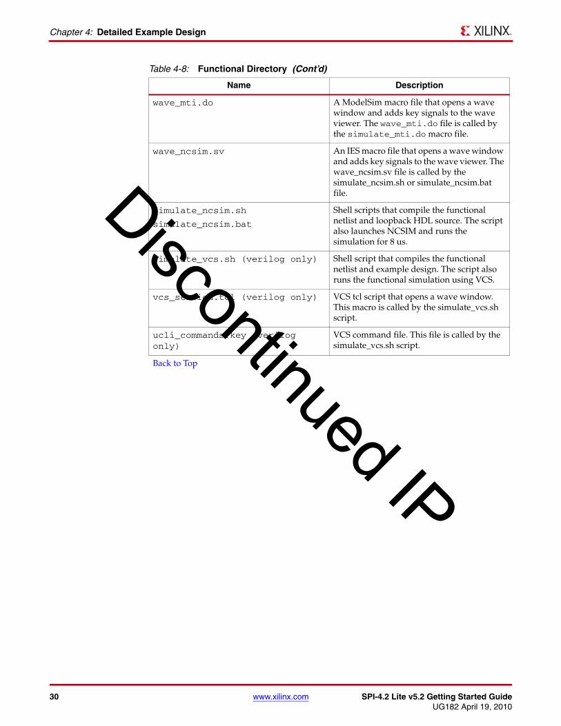
Table 4-8: Functional Directory
Name Description
<project_dir>/<component_name>/simulation/functional
simulate_mti.do A ModelSim macro file that compiles the functional netlist, loopback HDL and demo HDL source. The script also loads and runs the simulation for 8 μs.
Discontinued IP
30 www.xilinx.com SPI-4.2 Lite v5.2 Getting Started GuideUG182 April 19, 2010
Chapter 4: Detailed Example Design
wave_mti.do A ModelSim macro file that opens a wave window and adds key signals to the wave viewer. The wave_mti.do file is called by the simulate_mti.do macro file.
wave_ncsim.sv An IES macro file that opens a wave window and adds key signals to the wave viewer. The wave_ncsim.sv file is called by the simulate_ncsim.sh or simulate_ncsim.bat file.
simulate_ncsim.sh
simulate_ncsim.bat
Shell scripts that compile the functional netlist and loopback HDL source. The script also launches NCSIM and runs the simulation for 8 us.
simulate_vcs.sh (verilog only) Shell script that compiles the functional netlist and example design. The script also runs the functional simulation using VCS.
vcs_session.tcl (verilog only) VCS tcl script that opens a wave window. This macro is called by the simulate_vcs.sh script.
ucli_commands.key (verilog only)
VCS command file. This file is called by the simulate_vcs.sh script.
Back to Top
Table 4-8: Functional Directory (Cont’d)
Name Description
Discontinued IP

SPI-4.2 Lite v5.2 Getting Started Guide www.xilinx.com 31UG182 April 19, 2010
Implementation and Simulation Scripts
simulation/timingThe timing directory contains the timing simulation scripts.This directory is only generated for Full System Hardware Evaluation and Full license types.
Implementation and Simulation ScriptsThe implementation script is either a shell script or a batch file that runs the example design through the Xilinx tool flow. The scripts are located in the following directory:
<proj_dir>/<component_name>/implement/
The implementation scripts are parameterized based on the Design Entry Tool and Design Entry Language CORE Generator project options. If either of these project options are changed, the core must be regenerated to create the appropriate implementation scripts.
Table 4-9: Timing Directory
Name Description
<project_dir>/<component_name>/simulation/functional
simulate_mti.do A ModelSim macro file that compiles the post-par timing netlist and demo HDL source. The script also loads and runs the simulation for 8 μs.
wave_mti.do A ModelSim macro file that opens a wave window and adds key signals to the wave viewer. The wave_mti.do file is called by the simulate_mti.do macro file.
wave_ncsim.sv An IES macro file that opens a wave window and adds key signals to the wave viewer. The wave_ncsim.sv file is called by the simulate_ncsim.sh or simulate_ncsim.bat file.
simulate_ncsim.sh
simulate_ncsim.bat
Shell scripts that compile the post-par timing netlist and loopback HDL source. The script also launches NCSIM and runs the simulation for 8 us.
simulate_vcs.sh (verilog only) Shell script that compiles the post-par timing netlist and example design. The script also runs the functional simulation using VCS.
vcs_session.tcl (verilog only) VCS tcl script that opens a wave window. This macro is called by the simulate_vcs.sh script.
ucli_commands.key (verilog only)
VCS command file. This file is called by the simulate_vcs.sh script.
Back to Top
Discontinued IP
32 www.xilinx.com SPI-4.2 Lite v5.2 Getting Started GuideUG182 April 19, 2010
Chapter 4: Detailed Example Design
If the core was generated with the Full System Hardware Evaluation or the Full license, the implementation script is present and performs the following steps:
• Synthesizes the example design using the selected synthesis tool (Xilinx Synthesis Technology (XST) or Synplicity® Synplify)
• Runs ngdbuild to consolidate the core netlists, wrapper netlist, and constraints file into the common database
• Runs map to perform technology specific mapping of the design
• Runs par to perform place and route of the design
• Runs trce to perform static timing analysis of the routed design
• Runs bitgen to generate a bitstream for download to the target FPGA
• Runs netgen to generate a post-par simulation model for use in timing simulation
Simulation Script DetailsThe simulation scripts for ModelSim, IES, and VCS that simulate the demonstration test bench are located in one of the following directories:
<proj_dir>/<component_name>/simulation/{functional | timing }/
For functional simulation, the simulation script performs the following tasks.
• Compiles the simulation models provided with the core
• Compiles the loopback example design
• Compiles Source slave or user clocking module (if slave or user clocking is selected)
• Compiles Sink user clocking module (if user clocking is selected)
• Compiles the wrapper file, which instantiates the cores and the loopback
• Compiles the demonstration test bench
• Starts a simulation of the demonstration test bench
• Opens the waveform viewer and adds key signals
• Runs the simulation
For timing simulation, the simulation script performs the following tasks:
• Compiles the post-par design example, which includes the cores, the loopback, and the example clocking modules
• Compiles the demonstration test bench
• Starts a simulation of the demonstration test bench
• Opens the waveform viewer and adds key signals
• Runs the simulation
Example Design ConfigurationIn the example design, a Loopback Module is connected to the user interface of the SPI-4.2 Lite core. In a typical design, the user interface would be connected directly to the user’s design. The SPI-4.2 Interface, which is the interface defined by the OIF-SPI4-02.1 specification, typically connects to a SPI-4.2 PHY layer device or network processor. The
Discontinued IP

SPI-4.2 Lite v5.2 Getting Started Guide www.xilinx.com 33UG182 April 19, 2010
Example Design Configuration
architecture of the example design modules and their interfaces to the SPI-4.2 Lite core are shown in Figure 4-1.
Loopback ModuleThe Loopback Module connects to the user interface of the SPI-4.2 Lite Sink and Source cores. There is a Read Module that accesses packet data from the Sink FIFO and a Write Module that transfers data into the Source FIFO. The Read Module polls the status signals SnkFFEmpty_n and SnkFFAlmostEmpty_n to determine whether it can perform a read from the Sink FIFO. The Write Module polls SrcFFAlmostFull_n to determine whether it can transfer data into the Source FIFO.
Basic Loopback OperationWhen the Almost Full flag (SrcFFAlmostFull_n) is deasserted, the Write Module asserts a read request (RReq) that is sent to the Read Module. When a read request is received, the Read Module verifies that the FIFO is not empty and initiates a read from the Sink FIFO. On the next cycle, the data appears on SnkFFData and SnkFFValid is asserted. SnkFFValid drives the SrcFFWrEn_n signal directly, which enables the writing of data into the Source FIFO. The transfer of data continues until the Source FIFO becomes almost full or the Sink FIFO becomes empty. If the Source FIFO becomes almost full, all outstanding data is written into the Source FIFO and the transfer of data between the FIFOs is halted.
X-Ref Target - Figure 4-1
Figure 4-1: Example Design Configuration
SPI-4.2 Lite CoreLoopBack Module
SinkInterface
SourceInterface
Write Module
Read Module
SnkFFData
SnkFFAddr
SnkFFMod
SnkFFSOP
SnkFFEOP
SnkFFErr
SrcFFData
SrcFFAddr
SrcFFMod
SrcFFSOP
SrcFFEOP
SrcFFErr
SrcFFWrEn_n
SrcFFAlmostFull_n
SnkFFValid
WriteState
Machine
SnkFFAlmostEmpty_nSnkFFEmpty_n
SnkFFRdEn_nReadState
Machine
RegisterBank
RAck
RReq
Discontinued IP

34 www.xilinx.com SPI-4.2 Lite v5.2 Getting Started GuideUG182 April 19, 2010
Chapter 4: Detailed Example Design
Demonstration Test Bench The demonstration test bench emulates a PHY device by generating and receiving packet data across the SPI-4.2 interface. Figure 4-2 illustrates the interface between the demonstration test bench and the SPI-4.2 Lite core.
The modules for sending data and status are described in “Customizing the Demonstration Test Bench,” later in this section. As described below and shown in Figure 4-3, the demonstration test bench consists of the following modules:
• Clock Generator
• Startup Module
• Stimulus Module
• Procedures Module
• Data Monitor
X-Ref Target - Figure 4-2
Figure 4-2: Demonstration Test Bench Connections
DemonstrationTestbench
StimulusModule
DataMonitor
StatusMonitor
SPI-4.2 Lite Core
Sink Core
UserSink
Interface
SPI-4.2Sink
Interface
Source Core
UserSource
Interface
SPI-4.2Source
Interface
TCtl_N
TCtl_P
TDat_N
TDat_P
TSClk
TStat
TDClk_N
TDClk_P
RCtl_N
RCtl_P
RDat_N
RDat_P
RSClk
RStat
RDClk_N
RDClk_P
IdleRequest
TrainingRequest
SnkDip2ErrRequest
Source Static Config Signals
Sink Static Config Signals
SrcInFrame
SnkInFrame
Discontinued IP

SPI-4.2 Lite v5.2 Getting Started Guide www.xilinx.com 35UG182 April 19, 2010
Demonstration Test Bench
• Status Monitor
• Testcase Module
Clock GeneratorThe Clock Generator creates all of the clocks that are used in the Design Example, including SysClk, RDClk2x, UserClk, TSClk, and SnkIdelayRefClk (if regional clocking is selected for the Sink core). These clocks are described in more detail in Table 4-10.
X-Ref Target - Figure 4-3
Figure 4-3: Test Bench Modules
Demonstration Testbench
TestcaseModule
StimulusModule
Static Config. Signals
TCDat
TCCtl
TCStat
TCChan
TCIdleRequest
TCTrainingRequest
TCSinkDip2ErrRequest
TCDIP2Request
CtlFull
FFWriteEn
SopErr
GetStatusChan
GetStatus
FullVec
StatusMonitor
SnkInFrame
DataMonitor SrcInFrame
Procedures
TestcasePackage
ClockGenerator
Discontinued IP
36 www.xilinx.com SPI-4.2 Lite v5.2 Getting Started GuideUG182 April 19, 2010
Chapter 4: Detailed Example Design
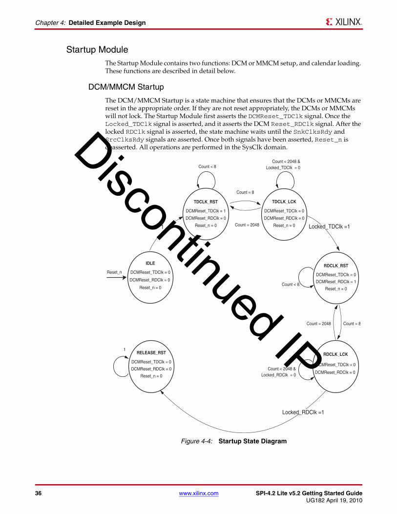
Startup ModuleThe Startup Module contains two functions: DCM or MMCM setup, and calendar loading. These functions are described in detail below.
DCM/MMCM Startup
The DCM/MMCM Startup is a state machine that ensures that the DCMs or MMCMs are reset in the appropriate order. If they are not reset appropriately, the DCMs or MMCMs will not lock. The Startup Module first asserts the DCMReset_TDClk signal. Once the Locked_TDClk signal is asserted, and it asserts the DCM Reset_RDClk signal. After the locked RDClk signal is asserted, the state machine waits until the SnkClksRdy and SrcClksRdy signals are asserted. Once both signals have been asserted, Reset_n is deasserted. All operations are performed in the SysClk domain.X-Ref Target - Figure 4-4
Figure 4-4: Startup State Diagram
IDLE
DCMReset_TDClk = 0
DCMReset_RDClk = 0
Reset_n = 0
TDCLK_RST
DCMReset_TDClk = 1
DCMReset_RDClk = 0
Reset_n = 0
DCMReset_TDClk = 0
DCMReset_RDClk = 0
Reset_n = 0
RDCLK_RST
DCMReset_TDClk = 0
DCMReset_RDClk = 1
Reset_n = 0
TDCLK_LCK
RDCLK_LCK
DCMReset_TDClk = 0
DCMReset_RDClk = 0 Reset_n = 0
Reset_n
Count < 8
Count = 8
Count = 8
1 Count = 2048
Count = 2048
Count < 8
1
Count < 2048 &Locked_TDClk = 0
Count < 2048 &Locked_RDClk = 0
RELEASE_RST
DCMReset_TDClk = 0
DCMReset_RDClk = 0
Locked_RDClk =1
Locked_TDClk =1
Discontinued IP

SPI-4.2 Lite v5.2 Getting Started Guide www.xilinx.com 37UG182 April 19, 2010
Demonstration Test Bench
Figure 4-4 illustrates the six states for the state machine.
• IDLE. Initial state after reset; DCMReset_TDClk is asserted.
• TDCLK_RST. Holds DCMReset_TDClk for eight cycles, then releases it.
• TDCLK_LCK. Waits for the Locked_TDClk signal.
• RDCLK_RST. Holds DCMReset_RDClk for eight cycles, then releases it.
• RDCLK_LCK. Waits for the Locked_RDClk signal.
• CLKS_RDY. Waits for SnkClksRdy and SrcClksRdy signals.
• RELEASE_RST. Deassert all of the DCMReset signals and release Reset_n.
Calendar Loader
The second function of the Startup module is the logic to load the calendars. The demonstration test bench reads the Sink calendar sequence and the Source calendar sequence from two different files and loads this information into the calendars of the Sink and Source cores and into the Stimulus module. It also loads the calendar into the Status Monitor so that it can identify which channel is receiving status. The calendar sequences can be modified as described in “Calendar Sequence Files (Sink and Source),” page 43.
Stimulus ModuleWhile the Testcase module in combination with the Procedures module are used to generate data and status, the Stimulus module is used to actually send this data to the SPI-4.2 Lite core. The Stimulus module either transmits data and status generated by the Testcase module, or it directly transmits training or idle data and framing status. In addition to sending status and data, the Stimulus module drives the Static Configuration Signals defined in the Testcase module. The behavior of the Stimulus module can be modified with constants defined in the Testcase package.
The Stimulus module also performs the following operations:
• Sends training or framing if the core is out of frame
• Inserts periodic training on RDat
• Ensures minimum SOP spacing is met
• Calculates DIP2 and DIP4 values
• Drives Source core request signals
• Merges SOP and EOP control words
The Stimulus module has two status inputs, SnkInFrame and SrcInFrame. If SnkInFrame is deasserted then the Stimulus module sends training patterns over RDat until SnkInFrame is asserted. If SrcInFrame is deasserted then the Stimulus module sends framing over TStat until SrcInFrame is asserted.
Procedures ModuleThe Procedures module is a package of functions instantiated in the Testcase module to simplify the sending of data and status to the Stimulus module. Using these functions, a user can create any desired sequence of data or status. The method by which the functions are called varies between languages and is described in the appendices.
Discontinued IP

38 www.xilinx.com SPI-4.2 Lite v5.2 Getting Started GuideUG182 April 19, 2010
Chapter 4: Detailed Example Design
The following supported functions are included in the Procedures module:
• send_packet
This procedure is used to transmit an entire packet of data. This procedure will always send an SOP control word before the burst of data and an EOP control word following the data burst.
• send_user_data
This procedure is used to transmit a burst of data. The presence of an SOP control word (before the burst of data) and an EOP control word (following the data burst) can be specified. The EOP can optionally specify an abort (ERR).
• send_idles
This procedure is used to send idle cycles.
• send_training
This procedure is used to send training patterns.
• sop_spacing
This procedure is used to send erred data by sending two SOP words in less than eight cycles. This function limits the number of cycles between the two SOPs to less than seven. This ensures that an SOP spacing error occurs.
• reset
This procedure, used to reset the interface to the stimulus module, should be called at the beginning of any testcase.
• send_status
This procedure is used to change the status (on TStat) for a particular channel.
• get_status
This procedure is called to check the status of a specific channel.
Data MonitorThe Data monitor is responsible for checking that the data sent from the demonstration test bench is the same as the data received from the core. This is accomplished by monitoring the RDat and RCtl signals that are input into the Sink core and comparing them to the TCtl and TDat signals output from the Source core. This is a simple comparison as long as the data being sent does not violate the OIF-SPI4-02.1 specification. If the specification is violated, the SPI-4.2 Lite cores modify the data to enforce compliance and the Data Monitor accounts for the modification before comparing TDat to RDat. In addition to the data, the monitor also verifies DIP4, SOP spacing, IDLE request, Training request, DATA_MAX_T, and ALPHA_DATA compliance. Changes in the testcase can create situations that cause the Data monitor to output warning messages. For more information on output warning messages, see Appendix C, “Data and Status Monitor Warnings.”
Status MonitorThe Status monitor inspects the RStat bus. In addition to verifying correct values for channel status, it compiles the current status for each channel into a vector, FullVec. FullVec is used by the Testcase module when the CHECK_RSTAT constant is set to stall data on RDat when the targeted channel is full. For more information on FullVec, see Table 4-11.
Discontinued IP

SPI-4.2 Lite v5.2 Getting Started Guide www.xilinx.com 39UG182 April 19, 2010
Demonstration Test Bench
In addition, the Status monitor calculates the DIP2 value for RStat and compares it with what is actually received. If there is an error it looks at the signal SnkDIP2ErrRequest to see if it was asserted and the error is expected.
Lastly, the signal SnkInFrame is created in the Status monitor by inverting SnkOof. This signal is used by the Stimulus module to send training. See Appendix C, “Data and Status Monitor Warnings.”
Customizing the Demonstration Test BenchThe Demonstration Test Bench can be used with default settings or customized to observe the behavior of the SPI-4.2 Lite core for different configurations.
The Demonstration Test Bench can be programmed to transmit a range of stimuli by modifying the following modules:
• Testcase Package: Contains constants used by the Testcase Module
• Testcase Module: Generates data and status
• Sink Calendar Sequence: Contains the channel order for the Sink core status
• Source Calendar Sequence: Contains the channel order for the Source core status
The following sections describe each module, including customization methods and the resulting behavior. The module descriptions are applicable to both VHDL and Verilog designs. Language specific details for VHDL are provided in Appendix A, “VHDL Details.” Language specific details and source code showing how to further randomize input to the SPI-4.2 Lite core for Verilog are provided in Appendix B, “Verilog Details.”
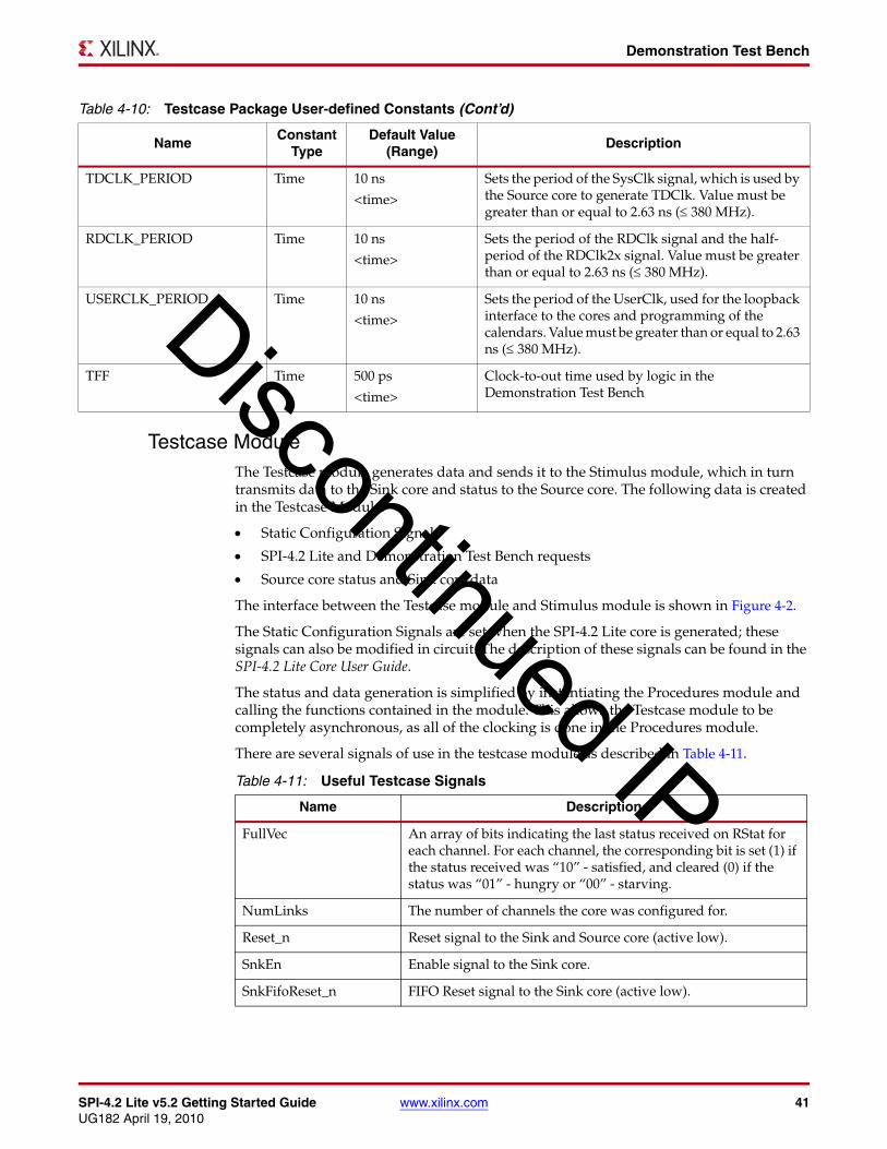
Testcase PackageThe Testcase package contains a list of constants that define the way in which the cores and demonstration test bench operate. Some of these are user defined, while others are defined when the core is generated. Table 4-10 provides test bench constants that can be modified. The remaining constants are set when the core is generated. Note that these can only be modified by regenerating the core in the CORE Generator tool.
Table 4-10: Testcase Package User-defined Constants
NameConstant
TypeDefault Value
(Range)Description
SNK_CAL_DATA String snk_calendar.dat
<filename>
Contains the name of the file with the Sink calendar sequence to be programmed.
SRC_CAL_DATA String src_calendar.dat
<filename>
Contains the name of the file with the Source calendar sequence to be programmed.
SNK_ALPHA_DATA Integer 3 <0 - 255> Sets the number of repetitions of the 20-word training pattern sent to the Sink core. (0 means do not send periodic training.)
SNK_DATA_MAX_T Integer 4000 <0-65535> Sets the number of cycles between training patterns sent to the Sink core. (0 means do not send periodic training.)
Discontinued IP

40 www.xilinx.com SPI-4.2 Lite v5.2 Getting Started GuideUG182 April 19, 2010
Chapter 4: Detailed Example Design
MERGE_PAYLOAD Integer 0 <0 or 1> Before data is sent on RDat, the Demonstration Test Bench can either merge an EOP and SOP control word into one payload control word, or it can leave them as two separate control words.
1: Merge EOP and SOP is enabled.
0: Merge EOP and SOP is disabled.
CHECK_RSTAT Integer 0 <0 or 1> The Demonstration Test Bench can operate in two modes with respect to the incoming status signal RStat. It either ignores the value on RStat or checks the value on RStat.
0: Ignore the value on RStat. The Test Bench continues to send data on RDat regardless of the status of the current channel.
1: Check the value on RStat. The Test Bench checks the status of the current channel before sending data to it. If the channel is satisfied (RStat = ‘10’), then the Test Bench does not send the packet of data and instead tries to send the next packet. The Test Bench sends the packet if the channel is starving or hungry (RStat = ‘01’ or ‘00’).
DATA_TYPE Integer 1 <0, 1, 2> Three types of data can be generated on RDat. The first type simply increments the data on each channel (e.g. sends 0, 1, 2 to channel 0, sends 0, 1, 2 to channel 1 , then sends 3, 4, 5 to channel 0). The second sends randomized data on RDat. The last type sends data read from the file <TEST_DATA_FILE>.
0: Send incremental data
1: Send random data
2: Send data read from file
TEST_DATA_FILE String data_file.dat
<filename>
Contains the name of the file to be read if DATA_TYPE = 2
RANDOM_SEED Integer (Verilog)
5431 <any 32-bit integer value>
Initial seed for the random number generator. To get different results between two runs of a random test bench, the seed must be changed. If the seed is not changed between runs, then every random number is the same as the previous run.
std_logic_vector(31 downto 0) (VHDL)
x”1537” <any 32-bit vector>
DATA_NUM_TRAIN_SEQ Integer 3 <0 - 255> Sets the number of complete training patterns that the Demonstration Test Bench has to receive on TDat (upon startup) before it stops sending framing sequences on TStat. Once this happens, the Demonstration Test Bench begins sending valid status.
Table 4-10: Testcase Package User-defined Constants (Cont’d)
NameConstant
TypeDefault Value
(Range)Description
Discontinued IP
SPI-4.2 Lite v5.2 Getting Started Guide www.xilinx.com 41UG182 April 19, 2010
Demonstration Test Bench
Testcase ModuleThe Testcase module generates data and sends it to the Stimulus module, which in turn transmits data to the Sink core and status to the Source core. The following data is created in the Testcase Module:
• Static Configuration Signals
• SPI-4.2 Lite and Demonstration Test Bench requests
• Source core status and Sink core data
The interface between the Testcase module and Stimulus module is shown in Figure 4-2.
The Static Configuration Signals are set when the SPI-4.2 Lite core is generated; these signals can also be modified in circuit. The description of these signals can be found in the SPI-4.2 Lite Core User Guide.
The status and data generation is simplified by instantiating the Procedures module and calling the functions contained in the module. This allows the Testcase module to be completely asynchronous, as all of the clocking is done in the Procedures module.
There are several signals of use in the testcase module as described in Table 4-11.
TDCLK_PERIOD Time 10 ns
<time>
Sets the period of the SysClk signal, which is used by the Source core to generate TDClk. Value must be greater than or equal to 2.63 ns (≤ 380 MHz).
RDCLK_PERIOD Time 10 ns
<time>
Sets the period of the RDClk signal and the half-period of the RDClk2x signal. Value must be greater than or equal to 2.63 ns (≤ 380 MHz).
USERCLK_PERIOD Time 10 ns
<time>
Sets the period of the UserClk, used for the loopback interface to the cores and programming of the calendars. Value must be greater than or equal to 2.63 ns (≤ 380 MHz).
TFF Time 500 ps
<time>
Clock-to-out time used by logic in the Demonstration Test Bench
Table 4-10: Testcase Package User-defined Constants (Cont’d)
NameConstant
TypeDefault Value
(Range)Description
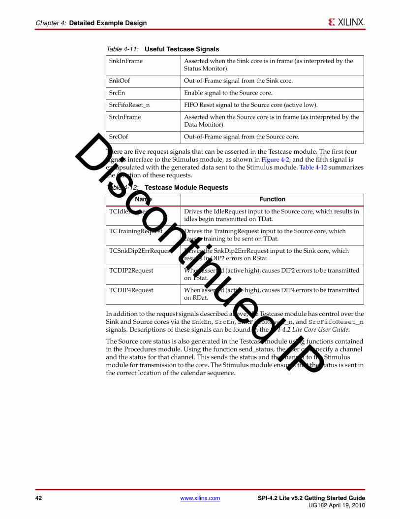
Table 4-11: Useful Testcase Signals
Name Description
FullVec An array of bits indicating the last status received on RStat for each channel. For each channel, the corresponding bit is set (1) if the status received was “10” - satisfied, and cleared (0) if the status was “01” - hungry or “00” - starving.
NumLinks The number of channels the core was configured for.
Reset_n Reset signal to the Sink and Source core (active low).
SnkEn Enable signal to the Sink core.
SnkFifoReset_n FIFO Reset signal to the Sink core (active low).
Discontinued IP
42 www.xilinx.com SPI-4.2 Lite v5.2 Getting Started GuideUG182 April 19, 2010
Chapter 4: Detailed Example Design
There are five request signals that can be asserted in the Testcase module. The first four signals interface to the Stimulus module, as shown in Figure 4-2, and the fifth signal is encapsulated with the generated data sent to the Stimulus module. Table 4-12 summarizes the function of these requests.
In addition to the request signals described above, the Testcase module has control over the Sink and Source cores via the SnkEn, SrcEn, SnkFifoReset_n, and SrcFifoReset_n signals. Descriptions of these signals can be found in the SPI-4.2 Lite Core User Guide.
The Source core status is also generated in the Testcase module using functions contained in the Procedures module. Using the function send_status, the user can specify a channel and the status for that channel. This sends the status and the channel to the Stimulus module for transmission to the core. The Stimulus module ensures that the status is sent in the correct location of the calendar sequence.
SnkInFrame Asserted when the Sink core is in frame (as interpreted by the Status Monitor).
SnkOof Out-of-Frame signal from the Sink core.
SrcEn Enable signal to the Source core.
SrcFifoReset_n FIFO Reset signal to the Source core (active low).
SrcInFrame Asserted when the Source core is in frame (as interpreted by the Data Monitor).
SrcOof Out-of-Frame signal from the Source core.
Table 4-12: Testcase Module Requests
Name Function
TCIdleRequest Drives the IdleRequest input to the Source core, which results in idles begin transmitted on TDat.
TCTrainingRequest Drives the TrainingRequest input to the Source core, which causes training to be sent on TDat.
TCSnkDip2ErrRequest Drives the SnkDip2ErrRequest input to the Sink core, which results in DIP2 errors on RStat.
TCDIP2Request When asserted (active high), causes DIP2 errors to be transmitted on TStat.
TCDIP4Request When asserted (active high), causes DIP4 errors to be transmitted on RDat.
Table 4-11: Useful Testcase Signals
Discontinued IP

SPI-4.2 Lite v5.2 Getting Started Guide www.xilinx.com 43UG182 April 19, 2010
Demonstration Test Bench
Calendar Sequence Files (Sink and Source) The snk_calendar.dat and src_calendar.dat files are used to define the order in which status is sent on the SPI-4.2 Lite Interface. The number of lines in a file is equal to the length of the calendar sequence (SnkCalendar_Len + 1 and SrcCalendar_Len +1). Each line of the file represents an 8-bit calendar entry in hexadecimal format. For example, a calendar that has a length of 5 and a sequence of <channel 0, channel 1, channel 0, channel 2, channel 3> can be generated by the following format:
0001000203
File names are defined in the Testcase package, and can be changed if desired. Discontinued IP
44 www.xilinx.com SPI-4.2 Lite v5.2 Getting Started GuideUG182 April 19, 2010
Chapter 4: Detailed Example Design
Discontinued IP

SPI-4.2 Lite v5.2 Getting Started Guide www.xilinx.com 45UG182 April 19, 2010
Appendix A
VHDL Details
Procedures ModuleThe Procedures module is a package of functions instantiated in the Testcase module to simplify the sending of data and status to the Stimulus module. By using these functions, the user can create any desired sequence of data or status. All functions are called from the Testcase module using the following format:
Format: <function name>(<IOBus>, <inputs>) Example: send_packet(ProBusR, 0, 40): A 40-byte long packet is sent on channel 0.
The Procedures module handles all clocking for the Testcase module. For an example of how these procedures are used, see the default file (pl4_lite_testcase.vhd) provided with the core.
All functions in the VHDL Procedures module utilize a passed-in record to inspect and modify the state of the interface with the Stimulus module. There are two such record types defined in the Procedures module: ProceduresRDClkBusType and ProceduresTSClkBusType, hereafter abbreviated PBr and PBt, respectively. For a usage example, see the provided testcase file (pl4_lite_testcase.vhd).
The tables in this section describe supported functions included in the Procedures module.
reset (PBr) and reset (PBt) procedures are used to initialize the PBr and PBt records. They must be called at the beginning of every testcase.
The send_packet procedure is used to transmit an entire packet of data. This procedure always sends a SOP control word before the burst of data and an EOP control word following the data burst. The EOPs (bits 14:13 of the control word following the burst) are automatically calculated from the number of bytes sent. See Table A-1.
Table A-1: send_packet (PBr, addr, bytes) Inputs
Name Range Description
ADDR 0 to 255 Channel on which the packet should be sent.
BYTES 1 to 255 Number of bytes to send on the selected channel.
Discontinued IP
46 www.xilinx.com SPI-4.2 Lite v5.2 Getting Started GuideUG182 April 19, 2010
Appendix A: VHDL Details
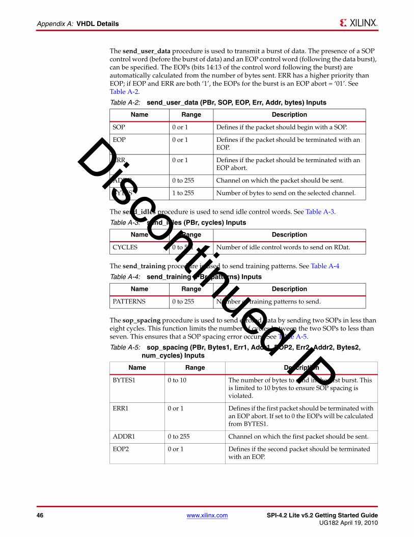
The send_user_data procedure is used to transmit a burst of data. The presence of a SOP control word (before the burst of data) and an EOP control word (following the data burst), can be specified. The EOPs (bits 14:13 of the control word following the burst) are automatically calculated from the number of bytes sent. ERR has a higher priority than EOP; if EOP and ERR are both ‘1’, the EOPs for the burst is an EOP abort = ‘01’. See Table A-2.
The send_idles procedure is used to send idle control words. See Table A-3.
The send_training procedure is used to send training patterns. See Table A-4
The sop_spacing procedure is used to send errored data by sending two SOPs in less than eight cycles. This function limits the number of cycles between the two SOPs to less than seven. This ensures that a SOP spacing error occurs. See Table A-5.
Table A-2: send_user_data (PBr, SOP, EOP, Err, Addr, bytes) Inputs
Name Range Description
SOP 0 or 1 Defines if the packet should begin with a SOP.
EOP 0 or 1 Defines if the packet should be terminated with an EOP.
ERR 0 or 1 Defines if the packet should be terminated with an EOP abort.
ADDR 0 to 255 Channel on which the packet should be sent.
BYTES 1 to 255 Number of bytes to send on the selected channel.
Table A-3: send_idles (PBr, cycles) Inputs
Name Range Description
CYCLES 0 to 511 Number of idle control words to send on RDat.
Table A-4: send_training (PBr, patterns) Inputs
Name Range Description
PATTERNS 0 to 255 Number of training patterns to send.
Table A-5: sop_spacing (PBr, Bytes1, Err1, Addr1, EOP2, Err2, Addr2, Bytes2, num_cycles) Inputs
Name Range Description
BYTES1 0 to 10 The number of bytes to send in the first burst. This is limited to 10 bytes to ensure SOP spacing is violated.
ERR1 0 or 1 Defines if the first packet should be terminated with an EOP abort. If set to 0 the EOPs will be calculated from BYTES1.
ADDR1 0 to 255 Channel on which the first packet should be sent.
EOP2 0 or 1 Defines if the second packet should be terminated with an EOP.
Discontinued IP
SPI-4.2 Lite v5.2 Getting Started Guide www.xilinx.com 47UG182 April 19, 2010
Procedures Module
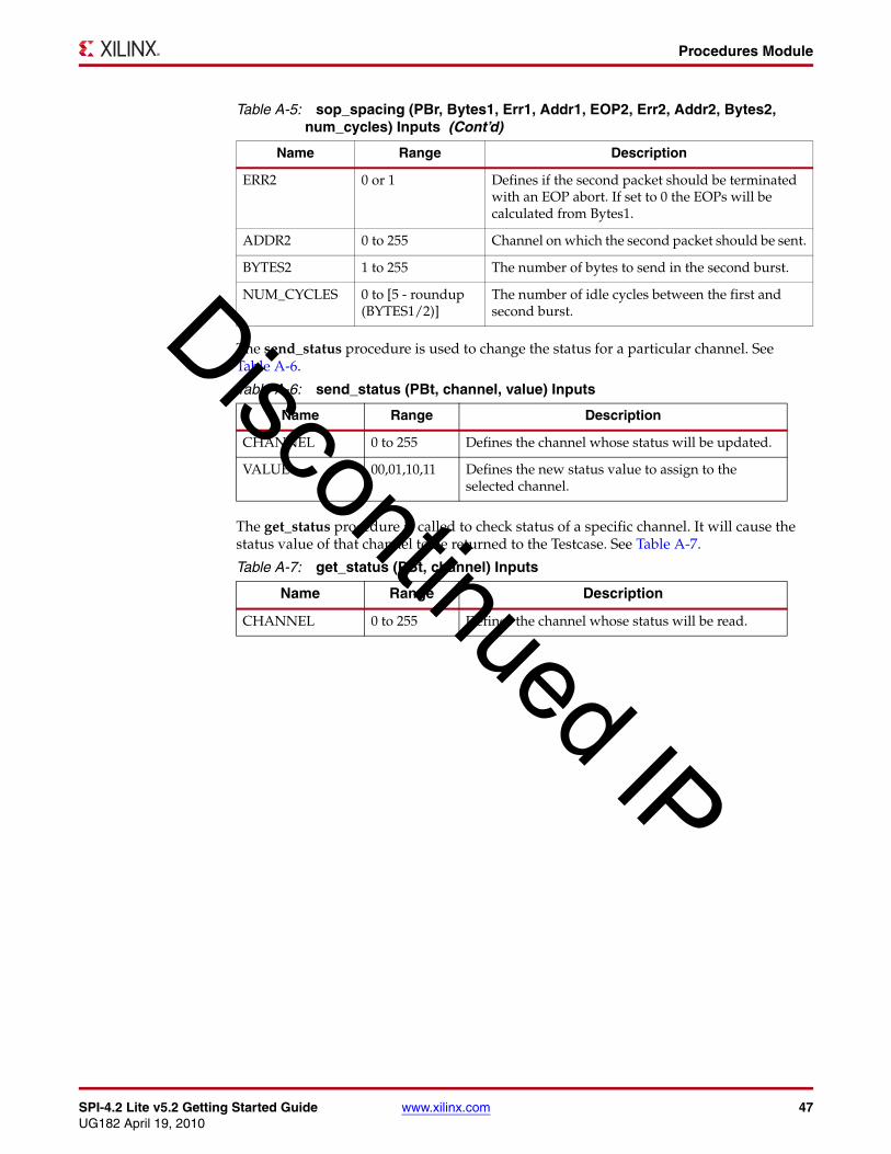
The send_status procedure is used to change the status for a particular channel. See Table A-6.
The get_status procedure is called to check status of a specific channel. It will cause the status value of that channel to be returned to the Testcase. See Table A-7.
ERR2 0 or 1 Defines if the second packet should be terminated with an EOP abort. If set to 0 the EOPs will be calculated from Bytes1.
ADDR2 0 to 255 Channel on which the second packet should be sent.
BYTES2 1 to 255 The number of bytes to send in the second burst.
NUM_CYCLES 0 to [5 - roundup (BYTES1/2)]
The number of idle cycles between the first and second burst.
Table A-6: send_status (PBt, channel, value) Inputs
Name Range Description
CHANNEL 0 to 255 Defines the channel whose status will be updated.
VALUE 00,01,10,11 Defines the new status value to assign to the selected channel.
Table A-7: get_status (PBt, channel) Inputs
Name Range Description
CHANNEL 0 to 255 Defines the channel whose status will be read.
Table A-5: sop_spacing (PBr, Bytes1, Err1, Addr1, EOP2, Err2, Addr2, Bytes2, num_cycles) Inputs (Cont’d)
Name Range Description
Discontinued IP

48 www.xilinx.com SPI-4.2 Lite v5.2 Getting Started GuideUG182 April 19, 2010
Appendix A: VHDL Details
Discontinued IP

SPI-4.2 Lite v5.2 Getting Started Guide www.xilinx.com 49UG182 April 19, 2010
Appendix B
Verilog Details
Procedures ModuleThe Procedures module is a package of functions instantiated in the Testcase module to simplify the sending of data and status to the Stimulus module. By using these functions, a user can create any desired sequence of data or status. All functions are called from the Testcase module using the following format:
Format: tasks.<function name>(<inputs>) Example: tasks.send_packet(0,40): A 40-byte long packet is sent on channel 0.
The Procedures module handles all clocking for the Testcase module. For an example of how these procedures are used, see the default file (pl4_lite_testcase.v) provided with the core.
The tables in this section describe the supported functions included in the Procedures module.
The reset procedure is used to reset the interface to the Stimulus Module. This procedure should be called at the beginning of any testcase.
The send_packet procedure is used to transmit an entire packet of data. This procedure will always send a SOP control word before the burst of data and an EOP control word following the data burst. The EOPS (bits 14:13 of the control word following the burst) are automatically calculated from the number of bytes sent. See Table B-1.
Table B-1: send_packet (Addr, bytes) Inputs
Name Range Description
ADDR 0 to 255 Channel on which the packet should be sent.
BYTES 1 to 255 Number of bytes to send on the selected channel.
Discontinued IP

50 www.xilinx.com SPI-4.2 Lite v5.2 Getting Started GuideUG182 April 19, 2010
Appendix B: Verilog Details
The send_user_data procedure is used to transmit a burst of data. The presence of a SOP control word (before the burst of data) and an EOP control word (following the data burst), can be specified. The EOPS (bits 14:13 of the control word following the burst) are automatically calculated from the number of bytes sent. ERR has a higher priority than EOP; if EOP and ERR are both ‘1’, the EOPs for the burst is an EOP abort = ‘01’. See Table B-2.
The send_idles procedure is used to send idle control words. See Table B-3
The send_training procedure is used to send training patterns. See Table B-4.
The sop_spacing procedure is used to send erred data by sending two SOPs in less than eight cycles. This function limits the number of cycles between the two SOPs to less than seven. This ensures that a SOP spacing error occurs. See Table B-5.
Table B-2: send_user_data (SOP, EOP, Err, Addr, bytes) Inputs
Name Range Description
SOP 0 or 1 Defines if the packet should begin with an SOP.
EOP 0 or 1 Defines if the packet should be terminated with an EOP.
ERR 0 or 1 Defines if the packet should be terminated with an EOP abort.
ADDR 0 to 255 Channel on which the packet should be sent.
BYTES 1 to 255 Number of bytes to send on the selected channel.
Table B-3: send_idles (cycles) Inputs
Name Range Description
CYCLES 0 to 511 Number of idle control words to send on RDat.
Table B-4: send_training (patterns) Inputs
Name Range Description
PATTERNS 0 to 255 Number of training patterns to send.
Table B-5: sop_spacing (Bytes1, Err1, Addr1, EOP2, Err2, Addr2, Bytes2, num_cycles) Inputs
Name Range Description
BYTES1 0 to 10 The number of bytes to send in the first burst. This is limited to 10 bytes to ensure SOP spacing is violated.
ERR1 0 or 1 Defines if the first packet should be terminated with an EOP abort. If set to 0 the EOPs will be calculated from BYTES1.
ADDR1 0 to 255 Channel on which the first packet should be sent.
EOP2 0 or 1 Defines if the second packet should be terminated with an EOP.
ERR2 0 or 1 Defines if the second packet should be terminated with an EOP abort. If set to 0 the EOPs will be calculated from Bytes1.
Discontinued IP
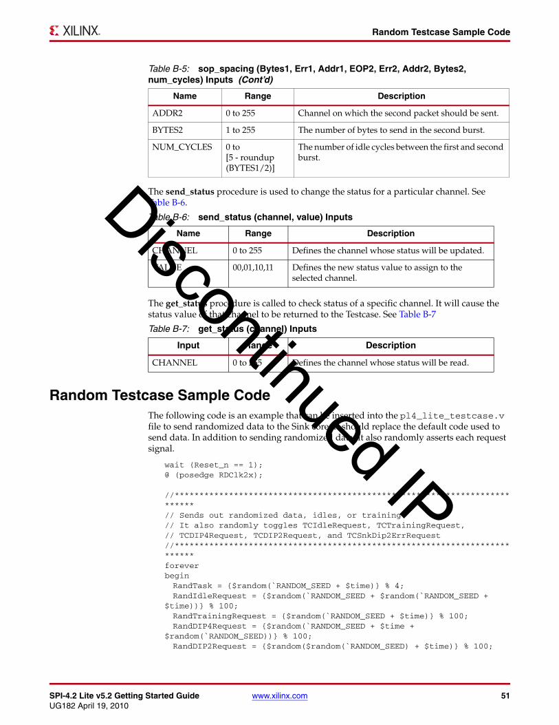
SPI-4.2 Lite v5.2 Getting Started Guide www.xilinx.com 51UG182 April 19, 2010
Random Testcase Sample Code
The send_status procedure is used to change the status for a particular channel. See Table B-6.
The get_status procedure is called to check status of a specific channel. It will cause the status value of that channel to be returned to the Testcase. See Table B-7
Random Testcase Sample CodeThe following code is an example that can be inserted into the pl4_lite_testcase.v file to send randomized data to the Sink core. It should replace the default code used to send data. In addition to sending randomized data, it also randomly asserts each request signal.
wait (Reset_n == 1);@ (posedge RDClk2x);
//**************************************************************************// Sends out randomized data, idles, or training.// It also randomly toggles TCIdleRequest, TCTrainingRequest,// TCDIP4Request, TCDIP2Request, and TCSnkDip2ErrRequest//**************************************************************************foreverbeginRandTask = {$random(`RANDOM_SEED + $time)} % 4;RandIdleRequest = {$random(`RANDOM_SEED + $random(`RANDOM_SEED +
$time))} % 100;RandTrainingRequest = {$random(`RANDOM_SEED + $time)} % 100;RandDIP4Request = {$random(`RANDOM_SEED + $time +
$random(`RANDOM_SEED))} % 100;RandDIP2Request = {$random($random(`RANDOM_SEED) + $time)} % 100;
ADDR2 0 to 255 Channel on which the second packet should be sent.
BYTES2 1 to 255 The number of bytes to send in the second burst.
NUM_CYCLES 0 to [5 - roundup (BYTES1/2)]
The number of idle cycles between the first and second burst.
Table B-6: send_status (channel, value) Inputs
Name Range Description
CHANNEL 0 to 255 Defines the channel whose status will be updated.
VALUE 00,01,10,11 Defines the new status value to assign to the selected channel.
Table B-7: get_status (channel) Inputs
Input Range Description
CHANNEL 0 to 255 Defines the channel whose status will be read.
Table B-5: sop_spacing (Bytes1, Err1, Addr1, EOP2, Err2, Addr2, Bytes2, num_cycles) Inputs (Cont’d)
Name Range Description
Discontinued IP

52 www.xilinx.com SPI-4.2 Lite v5.2 Getting Started GuideUG182 April 19, 2010
Appendix B: Verilog Details
RandSnkDip2ErrRequest = {$random(`RANDOM_SEED + $random($time))} % 100;
//Randomly set TCIdleRequest to 1if ((RandIdleRequest == 0) || (TCIdleRequest == 1))beginif (TCIdleRequest == 1)beginif (IdleRequestCnt > 0)beginIdleRequestCnt <= IdleRequestCnt - 1'b1;TCIdleRequest <= 1'b1;
endelsebeginIdleRequestCnt <= 'b0;TCIdleRequest <= 1'b0;
endendelsebeginTCIdleRequest <= 1'b1;IdleRequestCnt <= {$random(`RANDOM_SEED + $time)} % 9;
endend
//Randomly set TCTrainingRequest to 1if ((RandTrainingRequest == 0) || (TCTrainingRequest == 1))beginif (TCTrainingRequest == 1)beginif (TrainingRequestCnt > 0)beginTrainingRequestCnt <= TrainingRequestCnt - 1'b1;TCTrainingRequest <= 1'b1;
endelsebeginTrainingRequestCnt <= 'b0;TCTrainingRequest <= 1'b0;
endendelsebeginTCTrainingRequest <= 1'b1;TrainingRequestCnt <= {$random(`RANDOM_SEED + $time)} % 9;
endend
//Randomly set TCDIP4Request to 1if ((RandDIP4Request == 0) || (TCDIP4Request == 1))beginif (TCDIP4Request == 1)beginif (DIP4RequestCnt > 0)beginDIP4RequestCnt <= DIP4RequestCnt - 1'b1;TCDIP4Request <= 1'b1;
end
Discontinued IP
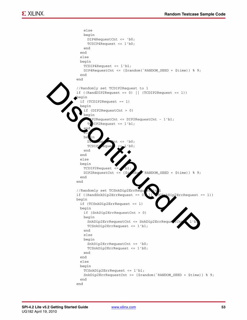
SPI-4.2 Lite v5.2 Getting Started Guide www.xilinx.com 53UG182 April 19, 2010
Random Testcase Sample Code
elsebeginDIP4RequestCnt <= 'b0;TCDIP4Request <= 1'b0;
endendelsebeginTCDIP4Request <= 1'b1;DIP4RequestCnt <= {$random(`RANDOM_SEED + $time)} % 9;
endend
//Randomly set TCDIP2Request to 1if ((RandDIP2Request == 0) || (TCDIP2Request == 1))beginif (TCDIP2Request == 1)beginif (DIP2RequestCnt > 0)beginDIP2RequestCnt <= DIP2RequestCnt - 1'b1;TCDIP2Request <= 1'b1;
endelsebeginDIP2RequestCnt <= 'b0;TCDIP2Request <= 1'b0;
endendelsebeginTCDIP2Request <= 1'b1;DIP2RequestCnt <= {$random(`RANDOM_SEED + $time)} % 9;
endend
//Randomly set TCSnkDip2ErrRequest to 1if ((RandSnkDip2ErrRequest == 0) || (TCSnkDip2ErrRequest == 1))beginif (TCSnkDip2ErrRequest == 1)beginif (SnkDip2ErrRequestCnt > 0)beginSnkDip2ErrRequestCnt <= SnkDip2ErrRequestCnt - 1'b1;TCSnkDip2ErrRequest <= 1'b1;
endelsebeginSnkDip2ErrRequestCnt <= 'b0;TCSnkDip2ErrRequest <= 1'b0;
endendelsebeginTCSnkDip2ErrRequest <= 1'b1;SnkDip2ErrRequestCnt <= {$random(`RANDOM_SEED + $time)} % 9;
endend
Discontinued IP

54 www.xilinx.com SPI-4.2 Lite v5.2 Getting Started GuideUG182 April 19, 2010
Appendix B: Verilog Details
//Sends a random sized packet to a random channelif (RandTask == 0)begintasks.send_packet({$random(`RANDOM_SEED + $time)} % (`NUM_CHANNELS
- 1), ($random(`RANDOM_SEED + $time) % 255) + 1'b1);end//Sends a random sized packet to a random channel. Also SOP, EOP, and//Err are randomizedelse if (RandTask == 1)begintasks.send_user_data({$random(`RANDOM_SEED + $time)} % 2,
{$random(`RANDOM_SEED + $time + $random(`RANDOM_SEED))} % 2, {$random(`RANDOM_SEED + $time + $random(`RANDOM_SEED + $time))} % 2, {$random(`RANDOM_SEED + $time)} % (`NUM_CHANNELS - 1), ($random(`RANDOM_SEED + $time) % 255) + 1'b1);end//Sends a random number of idles to the Sink Coreelse if (RandTask == 2)begintasks.send_idles(({$random(`RANDOM_SEED + $time)} % 10) + 1);
end//Sends a random number of training patterns to the sink coreelse if (RandTask == 3)begintasks.send_training(({$random(`RANDOM_SEED + $time)} % 10) + 1);
endelsebegin@ (posedge RDClk2x);$display("Out of Range: %0d", $time);
endend
Discontinued IP

SPI-4.2 Lite v5.2 Getting Started Guide www.xilinx.com 55UG182 April 19, 2010
Appendix C
Data and Status Monitor Warnings
The Data and Status monitors continuously check data sent to and received from the demonstration test bench. There are several common warnings that occur when the Testcase module is modified. The warnings are listed and described below.
• TDat Warning: Source is segmenting packets <simulation time>
This warning means that the Source core is sending payload resumes in the middle of sending a burst. This is acceptable operation if SrcBurstMode = 0. If SrcBurstMode = 1, this should only occur if the maximum burst length is reached (as defined by SrcBurstLen).
• RStat Info: Sink is out of frame. Expect TDat mismatches <simulation time>
This indicates that the Sink core went out of frame during operation. Unless training or idles are being sent on RDat when this occurs, there will be data errors on TDat. This is because what is being sent in on RDat is no longer being transferred to TDat.
• RStat Info: Expected DIP2 mismatch received: SnkDip2ErrReqFlag = 1 <simulation time>
This indicates that a DIP2 error was detected on RStat. It is only a note and not an error because SnkDip2ErrReq was asserted, which means that a DIP2 error is expected.
• RDat Warning: Protocol Violation #4. Idle follows data on a non-credit boundary <simulation time>
This indicates that the SPI-4.2 Lite protocol was violated when data was sent from the demonstration test bench. The most likely cause is that send_user_data was used to send data without an EOPS, which ended on a non-credit boundary, then an idle was sent using send_idles.
• RDat Warning: Protocol Violation
Any RDat protocol violation occurred because of incorrectly formatted data transmitted from the Testcase Module (they are user created).
Discontinued IP

56 www.xilinx.com SPI-4.2 Lite v5.2 Getting Started GuideUG182 April 19, 2010
Appendix C: Data and Status Monitor Warnings
Discontinued IP
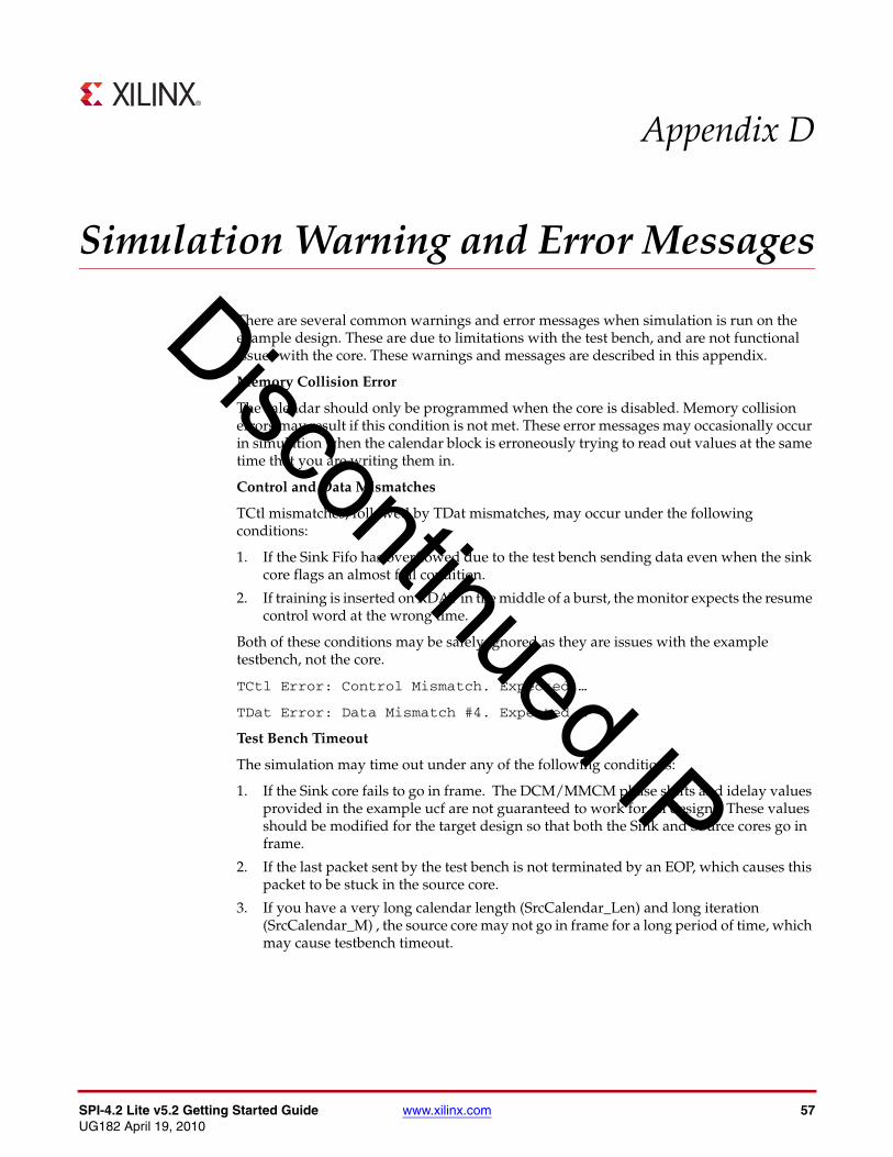
SPI-4.2 Lite v5.2 Getting Started Guide www.xilinx.com 57UG182 April 19, 2010
Appendix D
Simulation Warning and Error Messages
There are several common warnings and error messages when simulation is run on the example design. These are due to limitations with the test bench, and are not functional issues with the core. These warnings and messages are described in this appendix.
Memory Collision Error
The calendar should only be programmed when the core is disabled. Memory collision errors may result if this condition is not met. These error messages may occasionally occur in simulation when the calendar block is erroneously trying to read out values at the same time that you are writing them in.
Control and Data Mismatches
TCtl mismatches, followed by TDat mismatches, may occur under the following conditions:
1. If the Sink Fifo has overflowed due to the test bench sending data even when the sink core flags an almost full condition.
2. If training is inserted on RDAT in the middle of a burst, the monitor expects the resume control word at the wrong time.
Both of these conditions may be safely ignored as they are issues with the example testbench, not the core.
TCtl Error: Control Mismatch. Expected …
TDat Error: Data Mismatch #4. Expected …
Test Bench Timeout
The simulation may time out under any of the following conditions:
1. If the Sink core fails to go in frame. The DCM/MMCM phase shifts and idelay values provided in the example ucf are not guaranteed to work for all designs. These values should be modified for the target design so that both the Sink and Source cores go in frame.
2. If the last packet sent by the test bench is not terminated by an EOP, which causes this packet to be stuck in the source core.
3. If you have a very long calendar length (SrcCalendar_Len) and long iteration (SrcCalendar_M) , the source core may not go in frame for a long period of time, which may cause testbench timeout.
Discontinued IP

58 www.xilinx.com SPI-4.2 Lite v5.2 Getting Started GuideUG182 April 19, 2010
Appendix D: Simulation Warning and Error Messages
Discontinued IP