xilinx ug730 getting started with the virtex-6 fpga … getting started guide 5 ug730 (v1.1) june...
TRANSCRIPT
XPM 0402817-01
Getting Started with the Virtex-6 FPGA ML605 Embedded Kit
UG730 (v1.1) June 14, 2010
ML605 Getting Started Guide www.xilinx.com UG730 (v1.1) June 14, 2010
Xilinx is disclosing this user guide, manual, release note, and/or specification (the “Documentation”) to you solely for use in the development of designs to operate with Xilinx hardware devices. You may not reproduce, distribute, republish, download, display, post, or transmit the Documentation in any form or by any means including, but not limited to, electronic, mechanical, photocopying, recording, or otherwise, without the prior written consent of Xilinx. Xilinx expressly disclaims any liability arising out of your use of the Documentation. Xilinx reserves the right, at its sole discretion, to change the Documentation without notice at any time. Xilinx assumes no obligation to correct any errors contained in the Documentation, or to advise you of any corrections or updates. Xilinx expressly disclaims any liability in connection with technical support or assistance that may be provided to you in connection with the Information.
THE DOCUMENTATION IS DISCLOSED TO YOU “AS-IS” WITH NO WARRANTY OF ANY KIND. XILINX MAKES NO OTHER WARRANTIES, WHETHER EXPRESS, IMPLIED, OR STATUTORY, REGARDING THE DOCUMENTATION, INCLUDING ANY WARRANTIES OF MERCHANTABILITY, FITNESS FOR A PARTICULAR PURPOSE, OR NONINFRINGEMENT OF THIRD-PARTY RIGHTS. IN NO EVENT WILL XILINX BE LIABLE FOR ANY CONSEQUENTIAL, INDIRECT, EXEMPLARY, SPECIAL, OR INCIDENTAL DAMAGES, INCLUDING ANY LOSS OF DATA OR LOST PROFITS, ARISING FROM YOUR USE OF THE DOCUMENTATION.
© Copyright 2009–2010 Xilinx, Inc. XILINX, the Xilinx logo, Virtex, Spartan, ISE, and other designated brands included herein are trademarks of Xilinx in the United States and other countries. All other trademarks are the property of their respective owners.
Revision HistoryThe following table shows the revision history for this document.
Date Version Revision
12/08/09 1.0 Initial Xilinx release.
06/14/10 1.1 Changed “Embedded Development Kit” to “Embedded Kit” throughout. Updated ISE® software tool version from 11.1 to 12.1. Updated procedures and GUI screens for software version 12.1.
ML605 Getting Started Guide www.xilinx.com 3UG730 (v1.1) June 14, 2010
Revision History . . . . . . . . . . . . . . . . . . . . . . . . . . . . . . . . . . . . . . . . . . . . . . . . . . . . . . . . . . . . . 2
Preface: About This GuideAdditional Documentation . . . . . . . . . . . . . . . . . . . . . . . . . . . . . . . . . . . . . . . . . . . . . . . . . . . 5Additional Resources . . . . . . . . . . . . . . . . . . . . . . . . . . . . . . . . . . . . . . . . . . . . . . . . . . . . . . . . 6Conventions . . . . . . . . . . . . . . . . . . . . . . . . . . . . . . . . . . . . . . . . . . . . . . . . . . . . . . . . . . . . . . . . . 6
Typographical . . . . . . . . . . . . . . . . . . . . . . . . . . . . . . . . . . . . . . . . . . . . . . . . . . . . . . . . . . . . . 6Online Document . . . . . . . . . . . . . . . . . . . . . . . . . . . . . . . . . . . . . . . . . . . . . . . . . . . . . . . . . . 7
Getting Started with the Virtex-6 FPGA ML605 Embedded KitIntroduction . . . . . . . . . . . . . . . . . . . . . . . . . . . . . . . . . . . . . . . . . . . . . . . . . . . . . . . . . . . . . . . . . 9
ML605 Embedded Kit Contents . . . . . . . . . . . . . . . . . . . . . . . . . . . . . . . . . . . . . . . . . . . . . . 9What’s Inside the Box . . . . . . . . . . . . . . . . . . . . . . . . . . . . . . . . . . . . . . . . . . . . . . . . . . . . 9What’s Available Online . . . . . . . . . . . . . . . . . . . . . . . . . . . . . . . . . . . . . . . . . . . . . . . . . 10
Getting Started with the Video Demonstration . . . . . . . . . . . . . . . . . . . . . . . . . . . . . . . . 10Processor System Used for the Video Demo. . . . . . . . . . . . . . . . . . . . . . . . . . . . . . . . . . 10Video Demo Hardware Requirements . . . . . . . . . . . . . . . . . . . . . . . . . . . . . . . . . . . . . . 11Video Demo Hardware Setup Instructions. . . . . . . . . . . . . . . . . . . . . . . . . . . . . . . . . . . 11
Running the Video Demo . . . . . . . . . . . . . . . . . . . . . . . . . . . . . . . . . . . . . . . . . . . . . . . . . . 13Getting Started with the PetaLinux Demonstration . . . . . . . . . . . . . . . . . . . . . . . . . . . . 15
Processor System Used for the PetaLinux Demo . . . . . . . . . . . . . . . . . . . . . . . . . . . . . . 15PetaLinux Demo Hardware Setup Instructions . . . . . . . . . . . . . . . . . . . . . . . . . . . . . . . 16
Running the PetaLinux Demo . . . . . . . . . . . . . . . . . . . . . . . . . . . . . . . . . . . . . . . . . . . . . . 18Installation and Licensing of ISE Design Suite 12.1 . . . . . . . . . . . . . . . . . . . . . . . . . . 19
ISE 12.1 Software Installation . . . . . . . . . . . . . . . . . . . . . . . . . . . . . . . . . . . . . . . . . . . . . . . 19Downloading and Installing Tool Licenses . . . . . . . . . . . . . . . . . . . . . . . . . . . . . . . . . . . 24Communicating with the ML605 USB-UART . . . . . . . . . . . . . . . . . . . . . . . . . . . . . . . . . 29
Installing the USB-UART driver . . . . . . . . . . . . . . . . . . . . . . . . . . . . . . . . . . . . . . . . . . . 29Connecting to the ML605 UART. . . . . . . . . . . . . . . . . . . . . . . . . . . . . . . . . . . . . . . . . . . 29Configuring the Host Computer. . . . . . . . . . . . . . . . . . . . . . . . . . . . . . . . . . . . . . . . . . . 29Testing the USB-UART Driver Installation . . . . . . . . . . . . . . . . . . . . . . . . . . . . . . . . . . . 30
Next Steps . . . . . . . . . . . . . . . . . . . . . . . . . . . . . . . . . . . . . . . . . . . . . . . . . . . . . . . . . . . . . . . . . . 31Data Sheet . . . . . . . . . . . . . . . . . . . . . . . . . . . . . . . . . . . . . . . . . . . . . . . . . . . . . . . . . . . . . . . 33
DS758 ML605 Embedded Kit MicroBlaze Processor Subsystem Data Sheet . . . . . . . . . . 33Tutorials . . . . . . . . . . . . . . . . . . . . . . . . . . . . . . . . . . . . . . . . . . . . . . . . . . . . . . . . . . . . . . . . . 33
UG732 ML605 MicroBlaze Processor Subsystem Software Tutorial . . . . . . . . . . . . . . . . 33UG731 ML605 MicroBlaze Processor Subsystem Hardware Tutorial . . . . . . . . . . . . . . . 33
Reference Designs . . . . . . . . . . . . . . . . . . . . . . . . . . . . . . . . . . . . . . . . . . . . . . . . . . . . . . . . 33MicroBlaze Processor Subsystem . . . . . . . . . . . . . . . . . . . . . . . . . . . . . . . . . . . . . . . . . . 33MicroBlaze Processor Subsystem with Video Pipeline Demo. . . . . . . . . . . . . . . . . . . . . 33
Getting Help and Support . . . . . . . . . . . . . . . . . . . . . . . . . . . . . . . . . . . . . . . . . . . . . . . . . . . 34
Appendix A: Warranty
Table of Contents

ML605 Getting Started Guide www.xilinx.com 5UG730 (v1.1) June 14, 2010
Preface
About This Guide
This guide provides information for getting started with the Virtex®-6 FPGA ML605 Embedded Kit.
Additional DocumentationThe following documents are available for download athttp://www.xilinx.com/products/virtex6/.
• Virtex-6 Family Overview
This overview outlines the features and product selection of the Virtex-6 family.
• Virtex-6 FPGA Data Sheet: DC and Switching Characteristics
This data sheet contains the DC and switching characteristic specifications for the Virtex-6 family.
• Virtex-6 FPGA Packaging and Pinout Specifications
This specification includes the tables for device/package combinations and maximum I/Os, pin definitions, pinout tables, pinout diagrams, mechanical drawings, and thermal specifications.
• Virtex-6 FPGA Configuration User Guide
This all-encompassing configuration guide includes chapters on configuration interfaces (serial and parallel), multi-bitstream management, bitstream encryption, boundary-scan and JTAG configuration, and reconfiguration techniques.
• Virtex-6 FPGA SelectIO Resources User Guide
This guide describes the SelectIO™ resources available in all Virtex-6 devices.
• Virtex-6 FPGA Clocking Resources User Guide
This guide describes the clocking resources available in all the Virtex-6 devices, including the MMCM and Clock Buffers
• Virtex-6 FPGA Memory Resources User Guide
This guide describes the Virtex-6 device block RAM and FIFO capabilities.
• Virtex-6 FPGA GTH Transceivers User Guide
This guide describes the GTH transceivers available in all Virtex-6 HXT FPGAs except the XC6VHX250T and the XC6VHX380T in the FF1154 package.
• Virtex-6 FPGA GTX Transceivers User Guide
This guide describes the GTX transceivers available in all the Virtex-6 FPGAs except the XC6VLX760.
6 www.xilinx.com ML605 Getting Started GuideUG730 (v1.1) June 14, 2010
Preface: About This Guide
• Virtex-6 FPGA DSP48E1 Slice User Guide
This guide describes the DSP48E1 slice in Virtex-6 FPGAs and includes configuration examples.
• Virtex-6 FPGA Embedded Tri-Mode Ethernet MAC User Guide
This guide describes the dedicated tri-mode Ethernet media access controller (TEMAC) available in all the Virtex-6 FPGAs except the XC6VLX760.
• Virtex-6 FPGA System Monitor User Guide
This guide describes the System Monitor functionality.
• Virtex-6 FPGA PCB Designer’s Guide
This guide provides information on PCB design for Virtex-6 devices, with a focus on strategies for making design decisions at the PCB and interface level.
Additional ResourcesTo find additional documentation, see the Xilinx website at:
http://www.xilinx.com/support/documentation/index.htm.
To search the Answer Database of silicon, software, and IP questions and answers, or to create a technical support WebCase, see the Xilinx website at:
http://www.xilinx.com/support.
ConventionsThis document uses the following conventions. An example illustrates each convention.
TypographicalThe following typographical conventions are used in this document:
Convention Meaning or Use Example
Courier fontMessages, prompts, and program files that the system displays
speed grade: - 100
Courier boldLiteral commands that you enter in a syntactical statement
ngdbuild design_name
Helvetica bold
Commands that you select from a menu File → Open
Keyboard shortcuts Ctrl+C
ML605 Getting Started Guide www.xilinx.com 7UG730 (v1.1) June 14, 2010
Conventions
Online DocumentThe following conventions are used in this document:
Italic font
Variables in a syntax statement for which you must supply values
ngdbuild design_name
References to other manualsSee the Command Line Tools User Guide for more information.
Emphasis in textIf a wire is drawn so that it overlaps the pin of a symbol, the two nets are not connected.
Square brackets [ ]
An optional entry or parameter. However, in bus specifications, such as bus[7:0], they are required.
ngdbuild [option_name] design_name
Braces { }A list of items from which you must choose one or more lowpwr ={on|off}
Vertical bar |Separates items in a list of choices lowpwr ={on|off}
Vertical ellipsis...
Repetitive material that has been omitted
IOB #1: Name = QOUT’ IOB #2: Name = CLKIN’...
Horizontal ellipsis . . .Repetitive material that has been omitted
allow block block_name loc1 loc2 ... locn;
Convention Meaning or Use Example
Convention Meaning or Use Example
Blue textCross-reference link to a location in the current document
See the section “Additional Resources” for details.
Refer to “Title Formats” in Chapter 1 for details.
Blue, underlined text Hyperlink to a website (URL) Go to http://www.xilinx.com for the latest speed files.

8 www.xilinx.com ML605 Getting Started GuideUG730 (v1.1) June 14, 2010
Preface: About This Guide
ML605 Getting Started Guide www.xilinx.com 9UG730 (v1.1) June 14, 2010
Getting Started with the Virtex-6 FPGA ML605 Embedded Kit
IntroductionThe Virtex®-6 FPGA Embedded Kit conveniently delivers the key components of the Xilinx® Embedded Targeted Design Platform (TDP) required for developing embedded software and hardware in a wide range of applications in Broadcast, Industrial, Medical, Aerospace and Defense markets. For software developers, a familiar Eclipse-based IDE, GNU tools, OSes, libraries and a pre-verified reference design enables them to start programming right away. Similarly, hardware designers now have immediate access to a pre-integrated MicroBlaze™ processor subsystem that includes the most commonly used peripheral IP cores, enabling them to begin at once developing their custom logic.
This Getting Started Guide will walk you through the steps to set up the ML605 board and run the out-of-box video and Linux demonstrations that are designed to illustrate the flexibility and capability of a MicroBlaze processor subsystem for embedded design. Then, if you have not already installed the Xilinx ISE® software, you will be directed through the steps to install the software, get updates, and generate a license. Finally this guide will point you to next steps in using the embedded software and hardware tutorials included in this kit.
ML605 Embedded Kit Contents
What’s Inside the Box
• ML605 Evaluation Board with the XC6VLX240T-1FFG1156 FPGA along with:
• Power Supply
• Two USB Type-A to Mini-B 5-pin cables
• Ethernet Cable
• VGA to DVI Adapter
• CompactFlash card - 2 GB (with Embedded Kit demo)
• ISE Design Suite Embedded Edition: (device-locked) for Virtex-6 LX240T FPGA
• Xilinx ISE Design Suite 12.1 DVD which includes:
• ISE Foundation with ISE Simulator
• PlanAhead Design and Analysis Tool
• Embedded Development Kit (EDK)
• Xilinx Platform Studio (XPS)
10 www.xilinx.com ML605 Getting Started GuideUG730 (v1.1) June 14, 2010
Introduction
• Software Development Kit (SDK)
• ChipScope™ Pro logic analyzer
• Documentation
• ML605 Hardware Setup Guide
• UG730 Getting Started with the Virtex-6 FPGA ML605 Embedded Kit
• DS758 ML605 Embedded Kit MicroBlaze Processor Subsystem Data Sheet
• UG731 ML605 MicroBlaze Processor Subsystem Hardware Tutorial
• UG732 ML605 MicroBlaze Processor Subsystem Software Tutorial
• Reference Designs and Demonstrations
• Base MicroBlaze Processor Subsystem
• Video Demo
• Reference designs, demonstrations, documentation, and applications delivered on USB Flash drive to get started quickly
What’s Available Online
• License for ISE Design Suite 12.1 Embedded Edition
• http://www.xilinx.com/getproduct
• http://www.xilinx.com/tools/faq.htm
• Embedded Kit home page with Documentation and Reference Designs
• http://www.xilinx.com/v6embkit
• Technical Support
• http://www.xilinx.com/support/
Getting Started with the Video DemonstrationThis Virtex-6 Embedded Kit comes with a video demo available on the provided CompactFlash card. You can run this demo before installing any additional tools to get an overview of the features of the ML605 Evaluation Board using a MicroBlaze Processor Subsystem in the Virtex-6 LX240T FPGA.
Processor System Used for the Video Demo
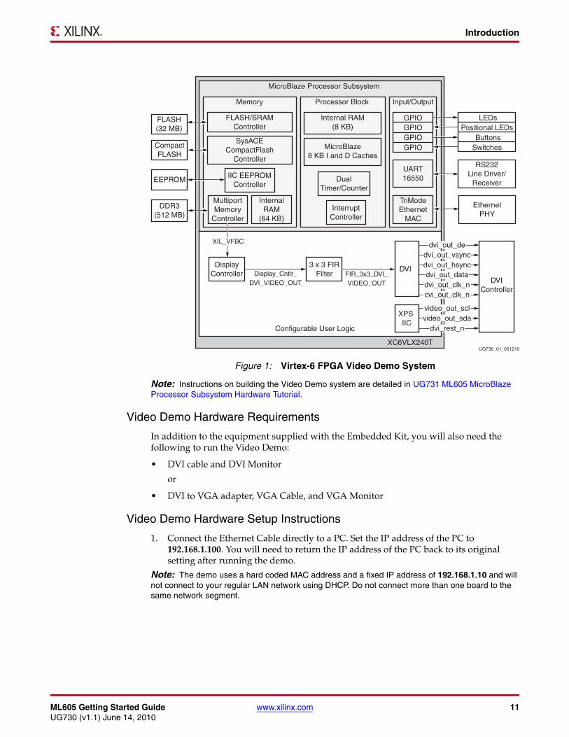
The provided demos use a pre-built Virtex-6 FPGA design (Figure 1) with the following features:
• MicroBlaze soft processor
• External DDR3 Memory Interface
• External Flash Memory Interface
• On-chip Memory (Block RAM)
• Integrated Tri-Mode Ethernet MAC (TEMAC)
• UART (connected from ML605 board via the USB-UART connector)
• Interrupt Controller (Intc) and Timer
• CompactFlash Interface (System ACE™ technology)
• GPIO (LEDs, LCD, Switches)
• Video Pipeline DSP Cores
ML605 Getting Started Guide www.xilinx.com 11UG730 (v1.1) June 14, 2010
Introduction
Note: Instructions on building the Video Demo system are detailed in UG731 ML605 MicroBlaze Processor Subsystem Hardware Tutorial.
Video Demo Hardware Requirements
In addition to the equipment supplied with the Embedded Kit, you will also need the following to run the Video Demo:
• DVI cable and DVI Monitor
or
• DVI to VGA adapter, VGA Cable, and VGA Monitor
Video Demo Hardware Setup Instructions
1. Connect the Ethernet Cable directly to a PC. Set the IP address of the PC to 192.168.1.100. You will need to return the IP address of the PC back to its original setting after running the demo.
Note: The demo uses a hard coded MAC address and a fixed IP address of 192.168.1.10 and will not connect to your regular LAN network using DHCP. Do not connect more than one board to the same network segment.
X-Ref Target - Figure 1
Figure 1: Virtex-6 FPGA Video Demo System
UG730_01_051210
Positional LEDsLEDs
UART16550
RS232Line Driver/
Receiver
EthernetPHY
TriModeEthernet
MAC
SwitchesButtons
Input/Output
MicroBlaze8 KB I and D Caches
Internal RAM(8 KB)
InterruptController
DualTimer/Counter
Processor Block
FLASH/SRAMController
SysACECompactFlash
Controller
MultiportMemory
Controller
InternalRAM
(64 KB)
IIC EEPROMController
FLASH(32 MB)
CompactFLASH
DDR3(512 MB)
EEPROM
Memory
MicroBlaze Processor Subsystem
XC6VLX240T
Configurable User Logic
GPIOGPIOGPIOGPIO
3 x 3 FIRFilter
dvi_out_dedvi_out_vsync
video_out_scl
dvi_rest_nvideo_out_sda
dvi_out_hsync
dvi_out_clk_ncvi_out_clk_n
dvi_out_dataDVI
Controller
XPS IIC
DVIDisplay
Controller FIR_3x3_DVI_VIDEO_OUT
Display_Cntlr_DVI_VIDEO_OUT
XIL_VFBC
12 www.xilinx.com ML605 Getting Started GuideUG730 (v1.1) June 14, 2010
Introduction
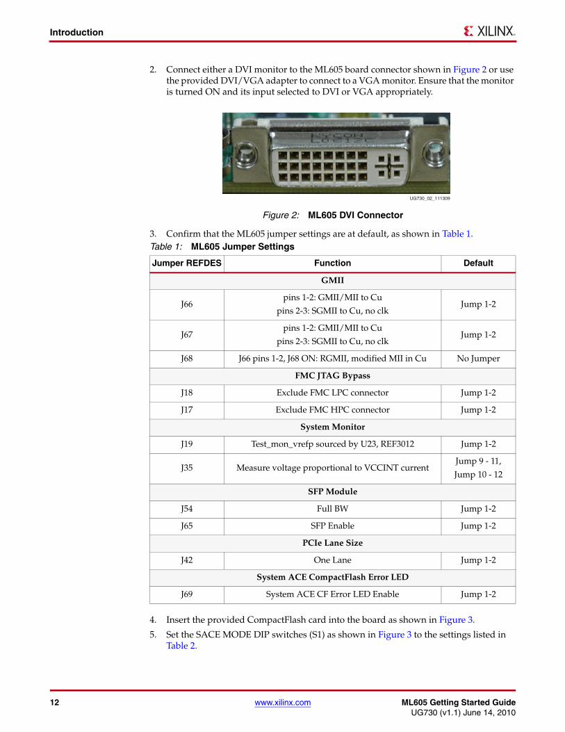
2. Connect either a DVI monitor to the ML605 board connector shown in Figure 2 or use the provided DVI/VGA adapter to connect to a VGA monitor. Ensure that the monitor is turned ON and its input selected to DVI or VGA appropriately.
3. Confirm that the ML605 jumper settings are at default, as shown in Table 1.
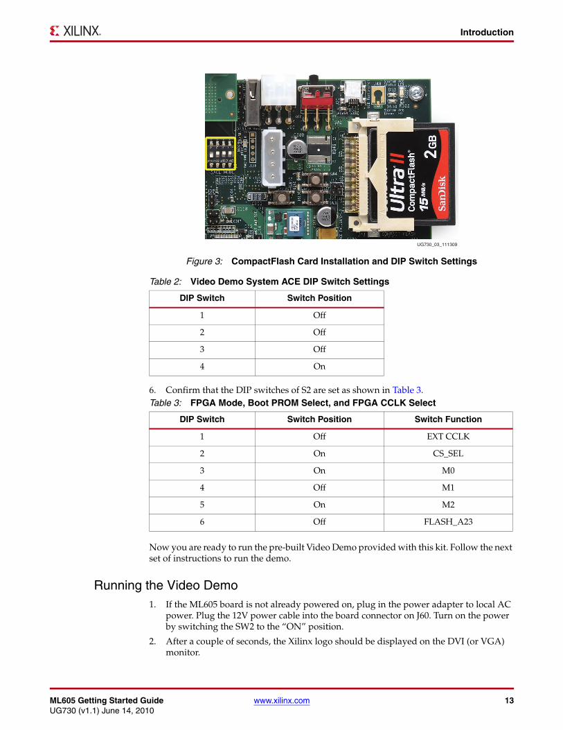
4. Insert the provided CompactFlash card into the board as shown in Figure 3.
5. Set the SACE MODE DIP switches (S1) as shown in Figure 3 to the settings listed in Table 2.
X-Ref Target - Figure 2
Figure 2: ML605 DVI Connector
Table 1: ML605 Jumper Settings
Jumper REFDES Function Default
GMII
J66pins 1-2: GMII/MII to Cu
pins 2-3: SGMII to Cu, no clkJump 1-2
J67pins 1-2: GMII/MII to Cu
pins 2-3: SGMII to Cu, no clkJump 1-2
J68 J66 pins 1-2, J68 ON: RGMII, modified MII in Cu No Jumper
FMC JTAG Bypass
J18 Exclude FMC LPC connector Jump 1-2
J17 Exclude FMC HPC connector Jump 1-2
System Monitor
J19 Test_mon_vrefp sourced by U23, REF3012 Jump 1-2
J35 Measure voltage proportional to VCCINT currentJump 9 - 11,
Jump 10 - 12
SFP Module
J54 Full BW Jump 1-2
J65 SFP Enable Jump 1-2
PCIe Lane Size
J42 One Lane Jump 1-2
System ACE CompactFlash Error LED
J69 System ACE CF Error LED Enable Jump 1-2
UG730_02_111309
ML605 Getting Started Guide www.xilinx.com 13UG730 (v1.1) June 14, 2010
Introduction
6. Confirm that the DIP switches of S2 are set as shown in Table 3.
Now you are ready to run the pre-built Video Demo provided with this kit. Follow the next set of instructions to run the demo.
Running the Video Demo1. If the ML605 board is not already powered on, plug in the power adapter to local AC
power. Plug the 12V power cable into the board connector on J60. Turn on the power by switching the SW2 to the “ON” position.
2. After a couple of seconds, the Xilinx logo should be displayed on the DVI (or VGA) monitor.
X-Ref Target - Figure 3
Figure 3: CompactFlash Card Installation and DIP Switch Settings
Table 2: Video Demo System ACE DIP Switch Settings
DIP Switch Switch Position
1 Off
2 Off
3 Off
4 On
Table 3: FPGA Mode, Boot PROM Select, and FPGA CCLK Select
DIP Switch Switch Position Switch Function
1 Off EXT CCLK
2 On CS_SEL
3 On M0
4 Off M1
5 On M2
6 Off FLASH_A23
UG730_03_111309
14 www.xilinx.com ML605 Getting Started GuideUG730 (v1.1) June 14, 2010
Introduction
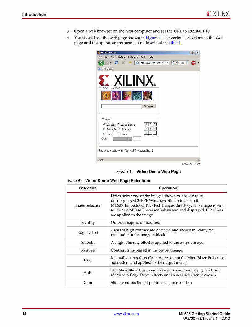
3. Open a web browser on the host computer and set the URL to 192.168.1.10.
4. You should see the web page shown in Figure 4. The various selections in the Web page and the operation performed are described in Table 4.
X-Ref Target - Figure 4
Figure 4: Video Demo Web Page
Table 4: Video Demo Web Page Selections
Selection Operation
Image Selection
Either select one of the images shown or browse to an uncompressed 24BPP Windows bitmap image in the ML605_Embedded_Kit\Test_Images directory. This image is sent to the MicroBlaze Processor Subsystem and displayed. FIR filters are applied to the image.
Identity Output image is unmodified.
Edge DetectAreas of high contrast are detected and shown in white; the remainder of the image is black.
Smooth A slight blurring effect is applied to the output image.
Sharpen Contrast is increased in the output image.
UserManually entered coefficients are sent to the MicroBlaze Processor Subsystem and applied to the output image.
AutoThe MicroBlaze Processor Subsystem continuously cycles from Identity to Edge Detect effects until a new selection is chosen.
Gain Slider controls the output image gain (0.0 - 1.0).
UG730_04_111309
ML605 Getting Started Guide www.xilinx.com 15UG730 (v1.1) June 14, 2010
Introduction
5. Try clicking the various options that adjust the image and notice the affect on the image displayed on the monitor.
6. Either select one of the displayed images or click Browse and select a new image from the ML605_Embedded_Kit\Test_Images directory.
The selected image should now be displayed on the DVI (or VGA) monitor.
7. Repeat step 5 and step 6 as desired.
Congratulations! You have now run a Video demo using the ML605 board with Virtex-6 LX240T FPGA and the MicroBlaze soft processor. Since you are provided with a fully configured MicroBlaze Processor Subsystem, you can start developing embedded software. Also since you are using an FPGA, you can fully customize this processor system. In order to do this, you have to install the ISE Design Suite 12.1 tools and the USB-UART driver on your computer. The Installation and Licensing of ISE Design Suite 12.1 section of this document will guide you through these steps.
Getting Started with the PetaLinux DemonstrationThis Virtex-6 Embedded Kit comes with a PetaLinux demo available on the provided CompactFlash card. PetaLinux is an Embedded Linux System Development Kit specifically targeting FPGA-based system-on-chip designs. You can run this demo to get an overview of the features of the ML605 Evaluation Board using a MicroBlaze Processor Subsystem in the Virtex-6 LX240T FPGA. More information about PetaLogix, including how to evaluate or purchase it, can be found at http://www.petalogix.com/petalinux.
Processor System Used for the PetaLinux Demo
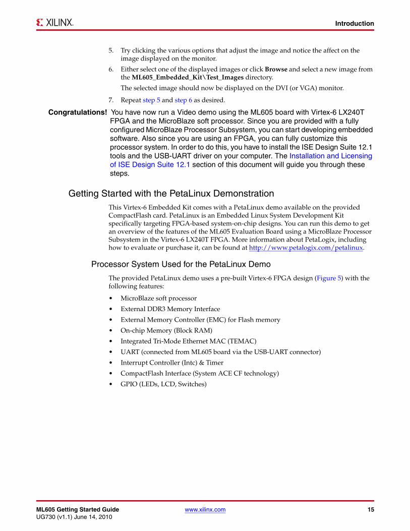
The provided PetaLinux demo uses a pre-built Virtex-6 FPGA design (Figure 5) with the following features:
• MicroBlaze soft processor
• External DDR3 Memory Interface
• External Memory Controller (EMC) for Flash memory
• On-chip Memory (Block RAM)
• Integrated Tri-Mode Ethernet MAC (TEMAC)
• UART (connected from ML605 board via the USB-UART connector)
• Interrupt Controller (Intc) & Timer
• CompactFlash Interface (System ACE CF technology)
• GPIO (LEDs, LCD, Switches)
16 www.xilinx.com ML605 Getting Started GuideUG730 (v1.1) June 14, 2010
Introduction
Note: Details about the system used for the PetaLinux demo can be found in DS758 ML605 Embedded Kit MicroBlaze Processor Subsystem Data Sheet.
PetaLinux Demo Hardware Setup Instructions
1. Install the USB-UART driver to your host computer by executing the steps specified in the Communicating with the ML605 USB-UART section.
2. Confirm that the ML605 jumper settings are at default, as shown in Table 5.
X-Ref Target - Figure 5
Figure 5: Virtex-6 FPGA PetaLinux System
UG730_05_051210
Positional LEDsLEDs
UART16550
RS232Line Driver/
Receiver
EthernetPHY
TriModeEthernet
MAC
SwitchesButtons
Input/Output
MicroBlaze8 KB I and D Caches
Internal RAM(8 KB)
InterruptController
DualTimer/Counter
Processor Block
FLASH/SRAMController
SysACECompactFlash
Controller
MultiportMemory
Controller
InternalRAM
(64 KB)
IIC EEPROMController
FLASH(32 MB
CompactFLASH
DDR3(512 MB)
EEPROM
Memory
MicroBlaze Processor Subsystem
XC6VLX240T
Configurable User Logic
User Access toExternal Memory
User Access toInternal Memory
User Interrupts
GPIOGPIOGPIOGPIO
Table 5: ML605 Jumper Settings
Jumper REFDES Function Default
GMII
J66pins 1-2: GMII/MII to Cu
pins 2-3: SGMII to Cu, no clkJump 1-2
J67pins 1-2: GMII/MII to Cu
pins 2-3: SGMII to Cu, no clkJump 1-2
J68 J66 pins 1-2, J68 ON: RGMII, modified MII in Cu No Jumper
FMC JTAG Bypass
J18 Exclude FMC LPC connector Jump 1-2
J17 Exclude FMC HPC connector Jump 1-2
ML605 Getting Started Guide www.xilinx.com 17UG730 (v1.1) June 14, 2010
Introduction
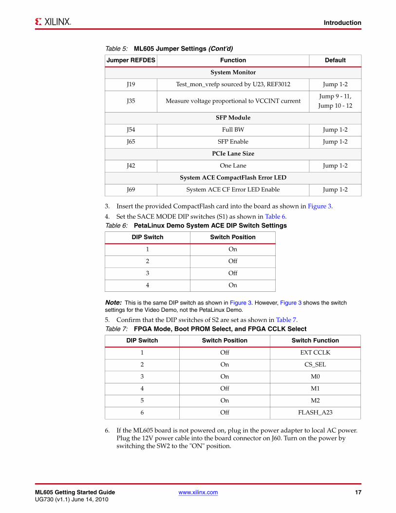
3. Insert the provided CompactFlash card into the board as shown in Figure 3.
4. Set the SACE MODE DIP switches (S1) as shown in Table 6.
Note: This is the same DIP switch as shown in Figure 3. However, Figure 3 shows the switch settings for the Video Demo, not the PetaLinux Demo.
5. Confirm that the DIP switches of S2 are set as shown in Table 7.
6. If the ML605 board is not powered on, plug in the power adapter to local AC power. Plug the 12V power cable into the board connector on J60. Turn on the power by switching the SW2 to the "ON" position.
System Monitor
J19 Test_mon_vrefp sourced by U23, REF3012 Jump 1-2
J35 Measure voltage proportional to VCCINT currentJump 9 - 11,
Jump 10 - 12
SFP Module
J54 Full BW Jump 1-2
J65 SFP Enable Jump 1-2
PCIe Lane Size
J42 One Lane Jump 1-2
System ACE CompactFlash Error LED
J69 System ACE CF Error LED Enable Jump 1-2
Table 6: PetaLinux Demo System ACE DIP Switch Settings
DIP Switch Switch Position
1 On
2 Off
3 Off
4 On
Table 7: FPGA Mode, Boot PROM Select, and FPGA CCLK Select
DIP Switch Switch Position Switch Function
1 Off EXT CCLK
2 On CS_SEL
3 On M0
4 Off M1
5 On M2
6 Off FLASH_A23
Table 5: ML605 Jumper Settings (Cont’d)
Jumper REFDES Function Default
18 www.xilinx.com ML605 Getting Started GuideUG730 (v1.1) June 14, 2010
Introduction
7. Open and configure a serial communications terminal utility program with the following settings:
• Baud Rate: 115200
• Data: 8 bit
• Parity: None
• Stop: 1 bit
• Flow Control: None
Note: Note: The baud rate (115200) for the PetaLinux demo is not the same baud rate (9600) used for the Video demo.
Now you are ready to run the PetaLinux pre-built demo provided with this kit. Follow the next set of instructions to run the demo.
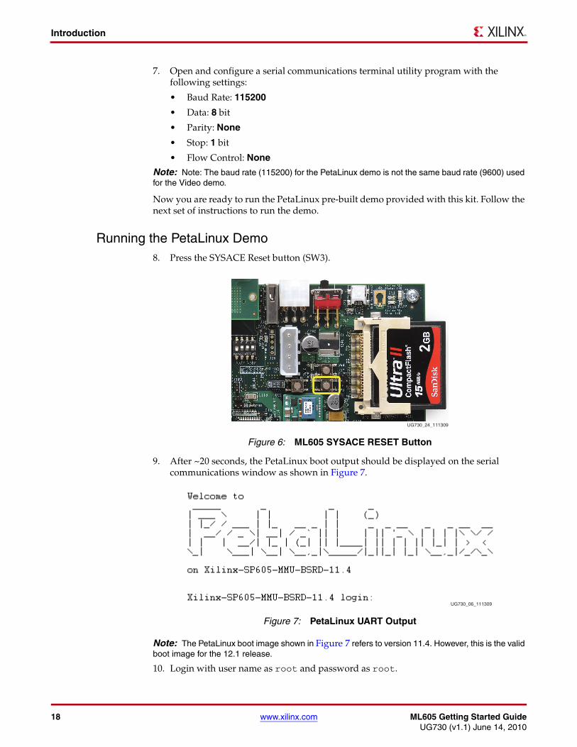
Running the PetaLinux Demo8. Press the SYSACE Reset button (SW3).
9. After ~20 seconds, the PetaLinux boot output should be displayed on the serial communications window as shown in Figure 7.
Note: The PetaLinux boot image shown in Figure 7 refers to version 11.4. However, this is the valid boot image for the 12.1 release.
10. Login with user name as root and password as root.
X-Ref Target - Figure 6
Figure 6: ML605 SYSACE RESET Button
X-Ref Target - Figure 7
Figure 7: PetaLinux UART Output
UG730_24_111309
UG730_06_111309
ML605 Getting Started Guide www.xilinx.com 19UG730 (v1.1) June 14, 2010
Installation and Licensing of ISE Design Suite 12.1
11. The PetaLinux image provided with the Embedded Kit supports many basic Linux commands. A list of some of the commands and tools available to be run can be found in the /bin directory.
Congratulations! You have now run the PetaLinux demo using the ML605 board with Virtex-6 LX240T FPGA and the MicroBlaze soft processor. Because you are provided with a fully configured MicroBlaze Processor Subsystem, you can start developing embedded software. Also because you are using an FPGA, you can fully customize this processor system. To do this, you have to install the ISE Design Suite 12.1 tools on your computer. The Installation and Licensing of ISE Design Suite 12.1 section of this document will guide you through these steps.
Installation and Licensing of ISE Design Suite 12.1This ML605 Embedded Kit comes with entitlement to a full seat of the ISE Design Suite: Embedded Edition that is device locked to a Virtex-6 LX240T. This software can be installed from the DVD or the Web installer can be downloaded fromhttp://www.xilinx.com/support/download/index.htm.
ISE 12.1 Software Installation1. Run the ISE Design Suite 12.1 Installer:
a. Option 1: Insert the ISE Design Suite 12.1 DVD included in this kit into your computer
- If the Installer does not start automatically, run the “xsetup” executable from the DVD
b. Option 2: Run the Web Installer that you can download fromhttp://www.xilinx.com/support/download/index.htm
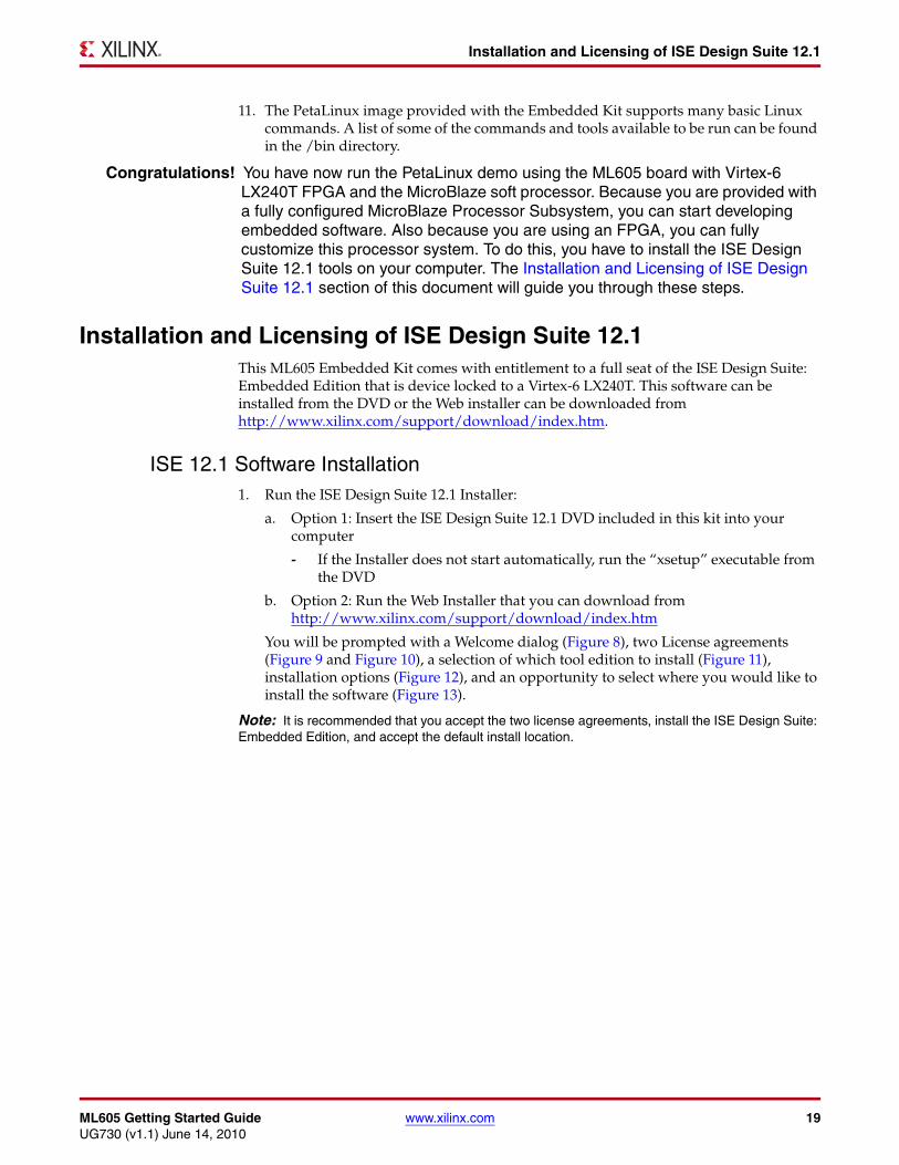
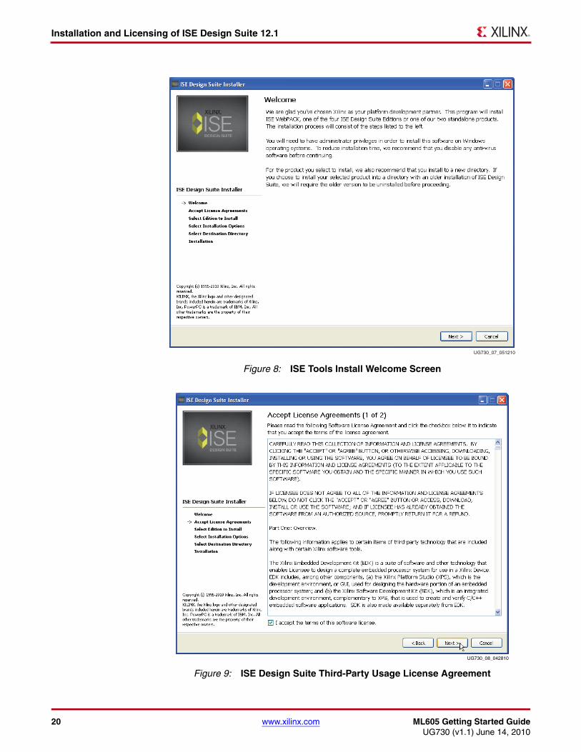
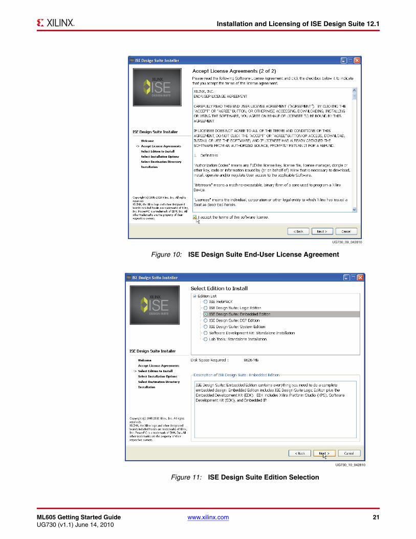
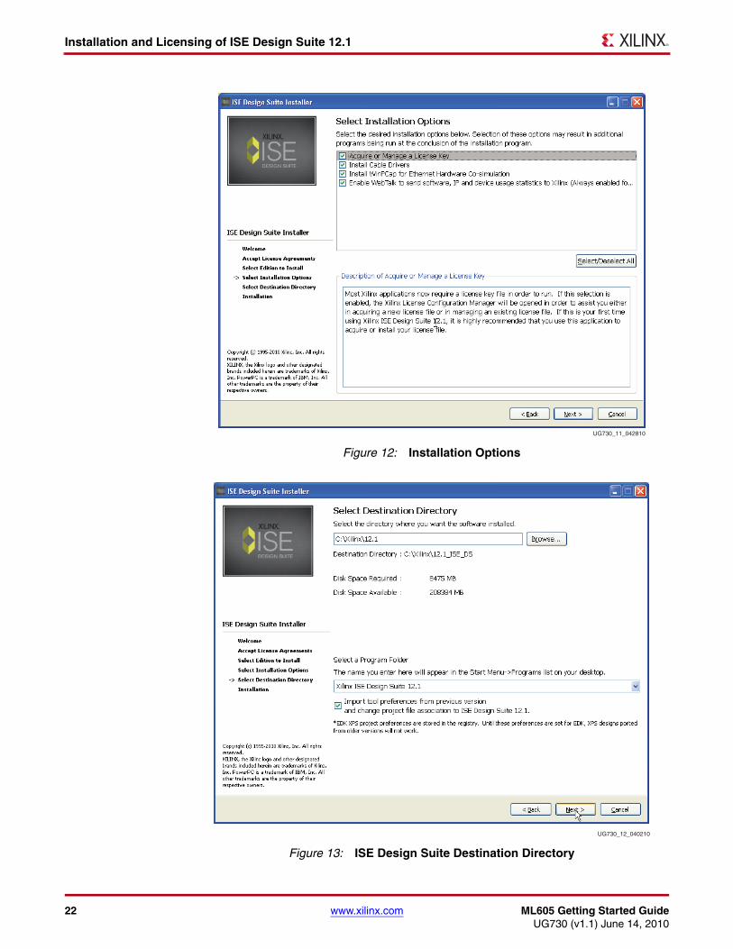
You will be prompted with a Welcome dialog (Figure 8), two License agreements (Figure 9 and Figure 10), a selection of which tool edition to install (Figure 11), installation options (Figure 12), and an opportunity to select where you would like to install the software (Figure 13).
Note: It is recommended that you accept the two license agreements, install the ISE Design Suite: Embedded Edition, and accept the default install location.
20 www.xilinx.com ML605 Getting Started GuideUG730 (v1.1) June 14, 2010
Installation and Licensing of ISE Design Suite 12.1
X-Ref Target - Figure 8
Figure 8: ISE Tools Install Welcome Screen
X-Ref Target - Figure 9
Figure 9: ISE Design Suite Third-Party Usage License Agreement
UG730_07_051210
UG730_08_042810
ML605 Getting Started Guide www.xilinx.com 21UG730 (v1.1) June 14, 2010
Installation and Licensing of ISE Design Suite 12.1
X-Ref Target - Figure 10
Figure 10: ISE Design Suite End-User License Agreement
X-Ref Target - Figure 11
Figure 11: ISE Design Suite Edition Selection
UG730_09_042810
UG730_10_042810
22 www.xilinx.com ML605 Getting Started GuideUG730 (v1.1) June 14, 2010
Installation and Licensing of ISE Design Suite 12.1
X-Ref Target - Figure 12
Figure 12: Installation Options
X-Ref Target - Figure 13
Figure 13: ISE Design Suite Destination Directory
UG730_11_042810
UG730_12_040210
ML605 Getting Started Guide www.xilinx.com 23UG730 (v1.1) June 14, 2010
Installation and Licensing of ISE Design Suite 12.1
2. Follow the rest of the steps presented by the installer, accepting the defaults to complete the installation.
Note: The DVD installation might take about one hour. The Web installation might take about three to ten hours based on Internet download speeds.
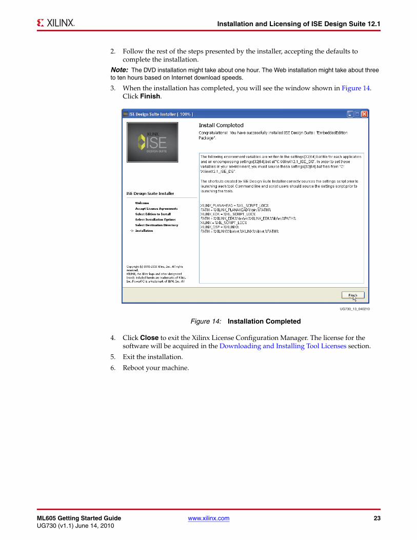
3. When the installation has completed, you will see the window shown in Figure 14. Click Finish.
4. Click Close to exit the Xilinx License Configuration Manager. The license for the software will be acquired in the Downloading and Installing Tool Licenses section.
5. Exit the installation.
6. Reboot your machine.
X-Ref Target - Figure 14
Figure 14: Installation Completed
UG730_13_040210
24 www.xilinx.com ML605 Getting Started GuideUG730 (v1.1) June 14, 2010
Installation and Licensing of ISE Design Suite 12.1
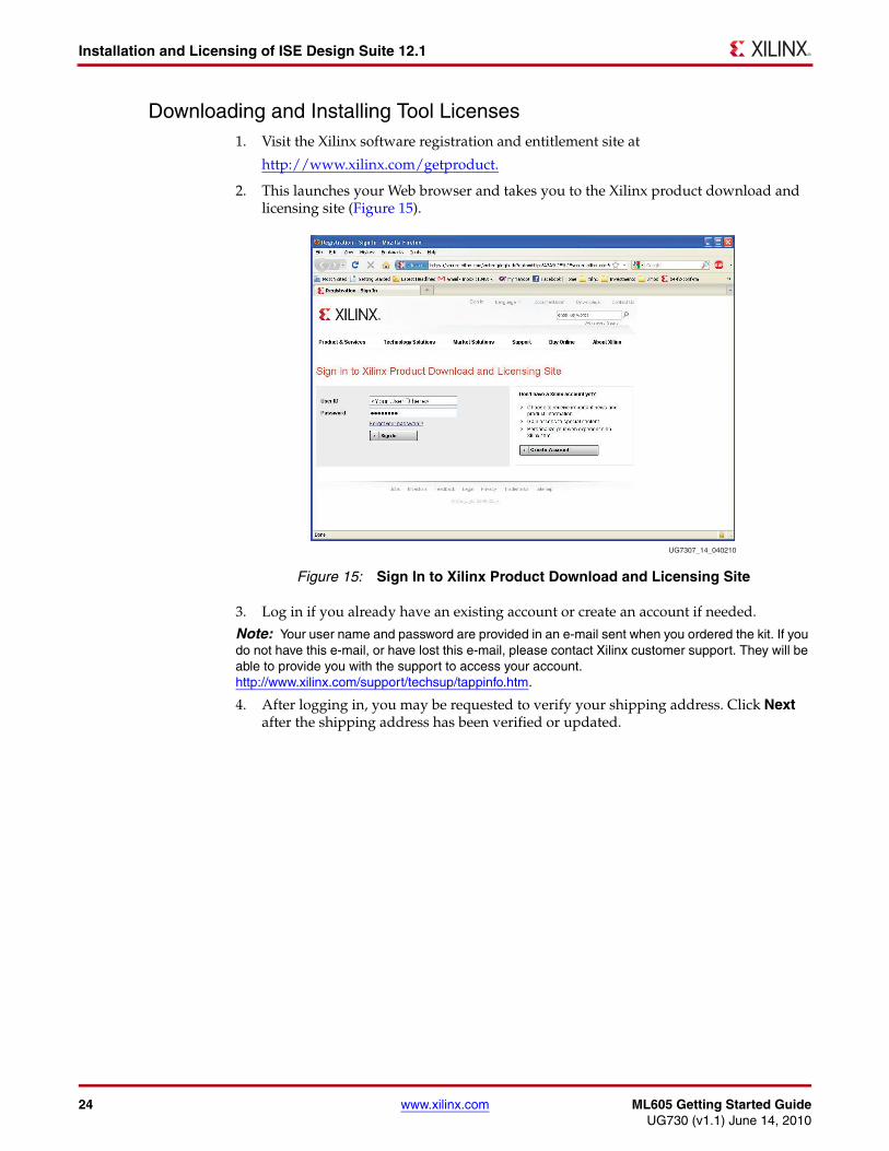
Downloading and Installing Tool Licenses1. Visit the Xilinx software registration and entitlement site at
http://www.xilinx.com/getproduct.
2. This launches your Web browser and takes you to the Xilinx product download and licensing site (Figure 15).
3. Log in if you already have an existing account or create an account if needed.
Note: Your user name and password are provided in an e-mail sent when you ordered the kit. If you do not have this e-mail, or have lost this e-mail, please contact Xilinx customer support. They will be able to provide you with the support to access your account.http://www.xilinx.com/support/techsup/tappinfo.htm.
4. After logging in, you may be requested to verify your shipping address. Click Next after the shipping address has been verified or updated.
X-Ref Target - Figure 15
Figure 15: Sign In to Xilinx Product Download and Licensing Site
UG7307_14_040210
ML605 Getting Started Guide www.xilinx.com 25UG730 (v1.1) June 14, 2010
Installation and Licensing of ISE Design Suite 12.1
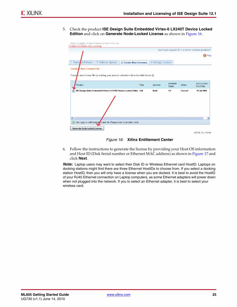
5. Check the product ISE Design Suite Embedded Virtex-6 LX240T Device Locked Edition and click on Generate Node-Locked License as shown in Figure 16.
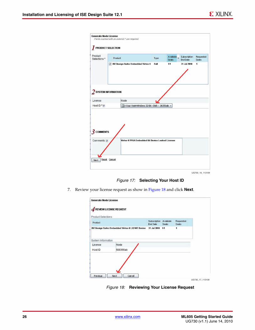
6. Follow the instructions to generate the license by providing your Host OS information and Host ID (Disk Serial number or Ethernet MAC address) as shown in Figure 17 and click Next.
Note: Laptop users may want to select their Disk ID or Wireless Ethernet card HostID. Laptops on docking stations might find there are three Ethernet HostIDs to choose from. If you select a docking station HostID, then you will only have a license when you are docked. It is best to avoid the HostID of your RJ45 Ethernet connection on Laptop computers, as some Ethernet adapters will power down when not plugged into the network. If you to select an Ethernet adapter, it is best to select your wireless card.
X-Ref Target - Figure 16
Figure 16: Xilinx Entitlement Center
UG730_15_113109
26 www.xilinx.com ML605 Getting Started GuideUG730 (v1.1) June 14, 2010
Installation and Licensing of ISE Design Suite 12.1
7. Review your license request as show in Figure 18 and click Next.
X-Ref Target - Figure 17
Figure 17: Selecting Your Host ID
X-Ref Target - Figure 18
Figure 18: Reviewing Your License Request
UG730_16_113109
UG730_17_113109
ML605 Getting Started Guide www.xilinx.com 27UG730 (v1.1) June 14, 2010
Installation and Licensing of ISE Design Suite 12.1
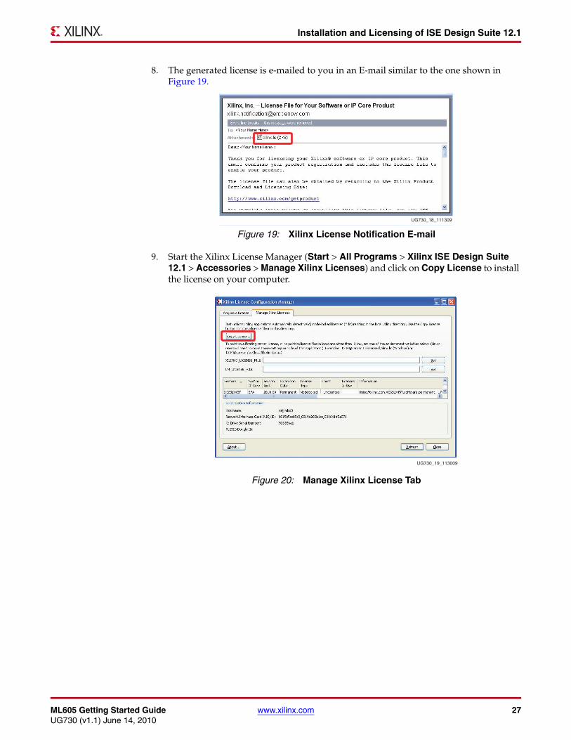
8. The generated license is e-mailed to you in an E-mail similar to the one shown in Figure 19.
9. Start the Xilinx License Manager (Start > All Programs > Xilinx ISE Design Suite 12.1 > Accessories > Manage Xilinx Licenses) and click on Copy License to install the license on your computer.
X-Ref Target - Figure 19
Figure 19: Xilinx License Notification E-mail
X-Ref Target - Figure 20
Figure 20: Manage Xilinx License Tab
UG730_18_111309
UG730_19_113009
28 www.xilinx.com ML605 Getting Started GuideUG730 (v1.1) June 14, 2010
Installation and Licensing of ISE Design Suite 12.1
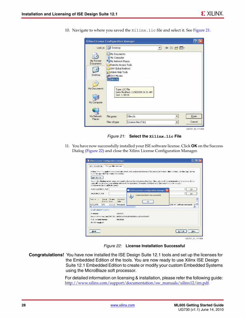
10. Navigate to where you saved the Xilinx.lic file and select it. See Figure 21.
11. You have now successfully installed your ISE software license. Click OK on the Success Dialog (Figure 22) and close the Xilinx License Configuration Manager.
Congratulations! You have now installed the ISE Design Suite 12.1 tools and set up the licenses for the Embedded Edition of the tools. You are now ready to use Xilinx ISE Design Suite 12.1 Embedded Edition to create or modify your custom Embedded Systems using the MicroBlaze soft processor.
For detailed information on licensing & installation, please refer the following guide: http://www.xilinx.com/support/documentation/sw_manuals/xilinx12/irn.pdf.
X-Ref Target - Figure 21
Figure 21: Select the Xilinx.lic File
X-Ref Target - Figure 22
Figure 22: License Installation Successful
UG727_20_111309
UG727_21_111309
ML605 Getting Started Guide www.xilinx.com 29UG730 (v1.1) June 14, 2010
Installation and Licensing of ISE Design Suite 12.1
Communicating with the ML605 USB-UART
Installing the USB-UART driver
1. Execute the installer for the Silicon Labs USB-UART Virtual COM Port (VCP) driver from the Drivers_and_Tools folder on the USB drive shipped with your ML605 Embedded Kit.
Drivers_and_Tools\CP210x_VCP_Win2K_XP_S2K3.exe
2. Follow the installer instructions. Restart your computer when instructed to do so.
Connecting to the ML605 UART
3. Connect a USB Type-A to Mini-B 5-pin cable between the ML605 USB-UART connector (J21) and the host computer.
4. Power on the ML605 Evaluation Board if it is not already powered on.
Configuring the Host Computer
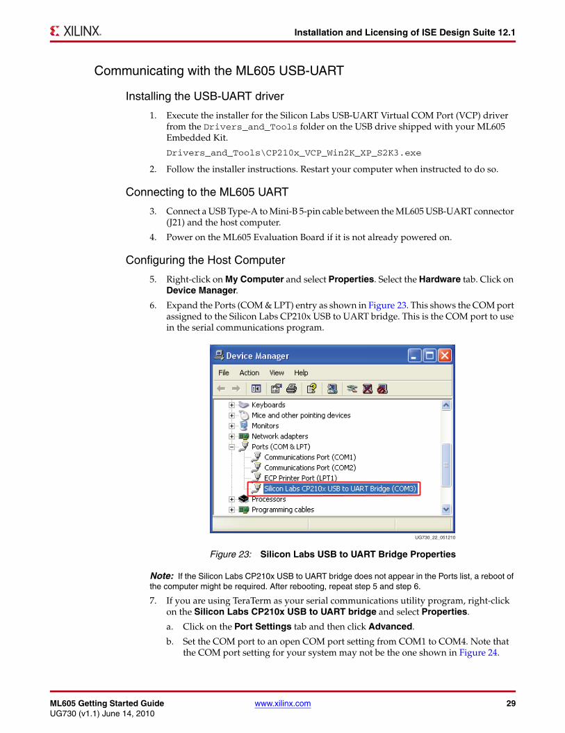
5. Right-click on My Computer and select Properties. Select the Hardware tab. Click on Device Manager.
6. Expand the Ports (COM & LPT) entry as shown in Figure 23. This shows the COM port assigned to the Silicon Labs CP210x USB to UART bridge. This is the COM port to use in the serial communications program.
Note: If the Silicon Labs CP210x USB to UART bridge does not appear in the Ports list, a reboot of the computer might be required. After rebooting, repeat step 5 and step 6.
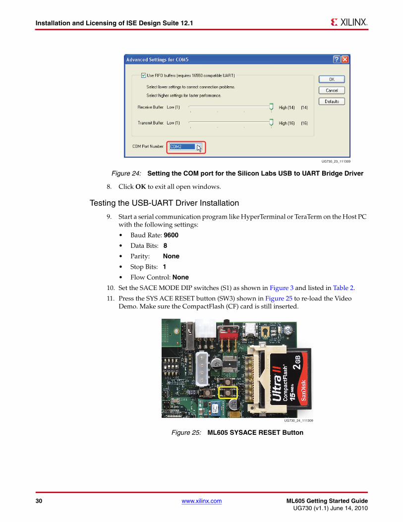
7. If you are using TeraTerm as your serial communications utility program, right-click on the Silicon Labs CP210x USB to UART bridge and select Properties.
a. Click on the Port Settings tab and then click Advanced.
b. Set the COM port to an open COM port setting from COM1 to COM4. Note that the COM port setting for your system may not be the one shown in Figure 24.
X-Ref Target - Figure 23
Figure 23: Silicon Labs USB to UART Bridge Properties
UG730_22_051210
30 www.xilinx.com ML605 Getting Started GuideUG730 (v1.1) June 14, 2010
Installation and Licensing of ISE Design Suite 12.1
8. Click OK to exit all open windows.
Testing the USB-UART Driver Installation
9. Start a serial communication program like HyperTerminal or TeraTerm on the Host PC with the following settings:
• Baud Rate: 9600
• Data Bits: 8
• Parity: None
• Stop Bits: 1
• Flow Control: None
10. Set the SACE MODE DIP switches (S1) as shown in Figure 3 and listed in Table 2.
11. Press the SYS ACE RESET button (SW3) shown in Figure 25 to re-load the Video Demo. Make sure the CompactFlash (CF) card is still inserted.
X-Ref Target - Figure 24
Figure 24: Setting the COM port for the Silicon Labs USB to UART Bridge Driver
UG730_23_111309
X-Ref Target - Figure 25
Figure 25: ML605 SYSACE RESET Button
UG730_24_111309
ML605 Getting Started Guide www.xilinx.com 31UG730 (v1.1) June 14, 2010
Next Steps
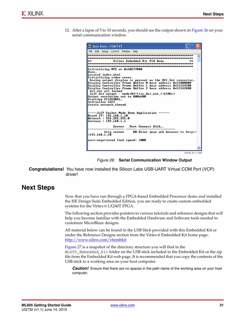
12. After a lapse of 5 to 10 seconds, you should see the output shown in Figure 26 on your serial communication window.
Congratulations! You have now installed the Silicon Labs USB-UART Virtual COM Port (VCP) driver!
Next StepsNow that you have run through a FPGA-based Embedded Processor demo and installed the ISE Design Suite Embedded Edition, you are ready to create custom embedded systems for the Virtex-6 LX240T FPGA.
The following section provides pointers to various tutorials and reference designs that will help you become familiar with the Embedded Hardware and Software tools needed to customize MicroBlaze designs.
All material below can be found in the USB Stick provided with this Embedded Kit or under the Reference Designs section from the Virtex-6 Embedded Kit home page:http://www.xilinx.com/v6embkit
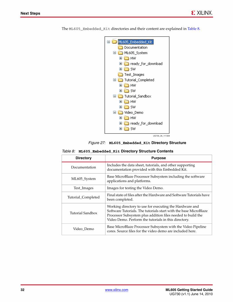
Figure 27 is a snapshot of the directory structure you will find in the ML605_Embedded_Kit folder on the USB stick included in the Embedded Kit or the zip file from the Embedded Kit web page. It is recommended that you copy the contents of the USB stick to a working area on your host computer.
Caution! Ensure that there are no spaces in the path name of the working area on your host computer.
X-Ref Target - Figure 26
Figure 26: Serial Communication Window Output
UG730_25_111309
32 www.xilinx.com ML605 Getting Started GuideUG730 (v1.1) June 14, 2010
Next Steps
The ML605_Embedded_Kit directories and their content are explained in Table 8.X-Ref Target - Figure 27
Figure 27: ML605_Embedded_Kit Directory Structure
Table 8: ML605_Embedded_Kit Directory Structure Contents
Directory Purpose
DocumentationIncludes the data sheet, tutorials, and other supporting documentation provided with this Embedded Kit.
ML605_SystemBase MicroBlaze Processor Subsystem including the software applications and platforms.
Test_Images Images for testing the Video Demo.
Tutorial_CompletedFinal state of files after the Hardware and Software Tutorials have been completed.
Tutorial Sandbox
Working directory to use for executing the Hardware and Software Tutorials. The tutorials start with the base MicroBlaze Processor Subsystem plus addition files needed to build the Video Demo. Perform the tutorials in this directory.
Video_Demo Base MicroBlaze Processor Subsystem with the Video Pipeline cores. Source files for the video demo are included here.
UG730_26_111309
ML605 Getting Started Guide www.xilinx.com 33UG730 (v1.1) June 14, 2010
Next Steps
Data Sheet
DS758 ML605 Embedded Kit MicroBlaze Processor Subsystem Data Sheet
• Documentation\ ds758_ML605_MicroBlaze_Processor_SubSystem_datasheet.pdf
• Detailed data sheet documentation of the MicroBlaze Processor Subsystem including block diagram, address map, pinout, FPGA design utilization and performance.
Tutorials
UG732 ML605 MicroBlaze Processor Subsystem Software Tutorial
• Documentation\ug732_ML605_software_tutorial.pdf
• This tutorial will guide you through the steps to start software development using Xilinx SDK (Eclipse IDE) and the MicroBlaze Processor Subsystem.
• This will show you how to create stand-alone (no OS) programs from simple Hello World designs to a more complex Board Test program.
• This will also show you how to boot a Linux platform for the MicroBlaze Processor Subsystem and provide pointers to start Linux development.
UG731 ML605 MicroBlaze Processor Subsystem Hardware Tutorial
• Documentation\ug731_ML605_hardware_tutorial.pdf
• This tutorial will guide you through the steps to open the MicroBlaze Processor Subsystem using Platform Studio and add the Video Pipeline DSP blocks to recreate the out-of-the-box Embedded Kit demo.
• This will also show you how to add ChipScope debug cores to monitor your embedded system using the ChipScope Logic Analyzer.
Reference Designs
MicroBlaze Processor Subsystem
• ML605_System
• This is the base MicroBlaze Processor Subsystem including the software applications and platforms.
MicroBlaze Processor Subsystem with Video Pipeline Demo
• Video_Demo
• This is the MicroBlaze Processor Subsystem with the Video Pipeline that was run as the power-on demo. Source files for the demo including the software application and platform are included here.

34 www.xilinx.com ML605 Getting Started GuideUG730 (v1.1) June 14, 2010
Getting Help and Support
Getting Help and SupportFor questions regarding products within your Product Entitlement Account, send an e-mail message to your regional Customer Service Representative:
• Canada, USA and South America - [email protected]
• Europe, Middle East, and Africa - [email protected]
• Asia Pacific including Japan - [email protected]
For technical support including the installation and use of your product license file you may contact Xilinx Online Technical Support at www.support.xilinx.com. On this site you will also find the following resources for assistance:
• Software, IP and Documentation Updates
• Access to Technical Support Web Tools
• Searchable Answer Database with Over 4,000 Solutions
• User Forums
• Training - Select instructor-led classes and recorded e-learning options
ML605 Getting Started Guide www.xilinx.com 35UG730 (v1.1) June 14, 2010
Appendix A
Warranty
THIS LIMITED WARRANTY applies solely to standard hardware development boards and standard hardware programming cables manufactured by or on behalf of Xilinx (“Development Systems”). Subject to the limitations herein, Xilinx warrants that Development Systems, when delivered by Xilinx or its authorized distributor, for ninety (90) days following the delivery date, will be free from defects in material and workmanship and will substantially conform to Xilinx publicly available specifications for such products in effect at the time of delivery. This limited warranty excludes: (i) engineering samples or beta versions of Development Systems (which are provided "AS-IS" without warranty); (ii) design defects or errors known as "errata"; (iii) Development Systems procured through unauthorized third parties; and (iv) Development Systems that have been subject to misuse, mishandling, accident, alteration, neglect, unauthorized repair or installation. Furthermore, this limited warranty shall not apply to the use of covered products in an application or environment that is not within Xilinx specifications or in the event of any act, error, neglect or default of Customer. For any breach by Xilinx of this limited warranty, the exclusive remedy of Customer and the sole liability of Xilinx shall be, at the option of Xilinx, to replace or repair the affected products, or to refund to Customer the price of the affected products. The availability of replacement products is subject to product discontinuation policies at Xilinx. Customer may not return product without first obtaining a customer return material authorization (RMA) number from Xilinx.
THE WARRANTIES SET FORTH HEREIN ARE EXCLUSIVE. XILINX DISCLAIMS ALL OTHER WARRANTIES, WHETHER EXPRESS, IMPLIED OR STATUTORY, INCLUDING, WITHOUT LIMITATION, ANY WARRANTY OF MERCHANTABILITY, FITNESS FOR A PARTICULAR PURPOSE, OR NON-INFRINGEMENT, AND ANY WARRANTY THAT MAY ARISE FROM COURSE OF DEALING, COURSE OF PERFORMANCE, OR USAGE OF TRADE. (2008.10)
Do not throw Xilinx products marked with the “crossed out wheelie bin” in the trash. Directive 2002/96/EC on waste electrical and electronic equipment (WEEE) requires the separate collection of WEEE. Your cooperation is essential in ensuring the proper management of WEEE and the protection of the environment and human health from potential effects arising from the presence of hazardous substances in WEEE. Return the marked products to Xilinx for proper disposal. Further information and instructions for free-of-charge return available at: http://www.xilinx.com/ehs/weee.htm.

36 www.xilinx.com ML605 Getting Started GuideUG730 (v1.1) June 14, 2010
Appendix A: Warranty