xilinx ug926 zynq-7000 all programmable soc: zc702 ... all programmable soc: zc702 evaluation kit...
TRANSCRIPT

0402905-01
Zynq-7000 All Programmable SoC:ZC702 Evaluation KitandVideo and Imaging Kit (ISE Design Suite 14.2)Getting Started Guide
UG926 (v2.0) September 18, 2012

Notice of DisclaimerThe information disclosed to you hereunder (the “Materials”) is provided solely for the selection and use of Xilinx products. To the maximum extent permitted by applicable law: (1) Materials are made available "AS IS" and with all faults, Xilinx hereby DISCLAIMS ALL WARRANTIES AND CONDITIONS, EXPRESS, IMPLIED, OR STATUTORY, INCLUDING BUT NOT LIMITED TO WARRANTIES OF MERCHANTABILITY, NON-INFRINGEMENT, OR FITNESS FOR ANY PARTICULAR PURPOSE; and (2) Xilinx shall not be liable (whether in contract or tort, including negligence, or under any other theory of liability) for any loss or damage of any kind or nature related to, arising under, or in connection with, the Materials (including your use of the Materials), including for any direct, indirect, special, incidental, or consequential loss or damage (including loss of data, profits, goodwill, or any type of loss or damage suffered as a result of any action brought by a third party) even if such damage or loss was reasonably foreseeable or Xilinx had been advised of the possibility of the same. Xilinx assumes no obligation to correct any errors contained in the Materials or to notify you of updates to the Materials or to product specifications. You may not reproduce, modify, distribute, or publicly display the Materials without prior written consent. Certain products are subject to the terms and conditions of the Limited Warranties which can be viewed at http://www.xilinx.com/warranty.htm; IP cores may be subject to warranty and support terms contained in a license issued to you by Xilinx. Xilinx products are not designed or intended to be fail-safe or for use in any application requiring fail-safe performance; you assume sole risk and liability for use of Xilinx products in Critical Applications: http://www.xilinx.com/warranty.htm#critapps.Automotive Applications DisclaimerXILINX PRODUCTS ARE NOT DESIGNED OR INTENDED TO BE FAIL-SAFE, OR FOR USE IN ANY APPLICATION REQUIRING FAIL-SAFE PERFORMANCE, SUCH AS APPLICATIONS RELATED TO: (I) THE DEPLOYMENT OF AIRBAGS, (II) CONTROL OF A VEHICLE, UNLESS THERE IS A FAIL-SAFE OR REDUNDANCY FEATURE (WHICH DOES NOT INCLUDE USE OF SOFTWARE IN THE XILINX DEVICE TO IMPLEMENT THE REDUNDANCY) AND A WARNING SIGNAL UPON FAILURE TO THE OPERATOR, OR (III) USES THAT COULD LEAD TO DEATH OR PERSONAL INJURY. CUSTOMER ASSUMES THE SOLE RISK AND LIABILITY OF ANY USE OF XILINX PRODUCTS IN SUCH APPLICATIONS. © Copyright 2012 Xilinx, Inc. Xilinx, the Xilinx logo, Artix, ISE, Kintex, Spartan, Virtex, Vivado, Zynq, and other designated brands included herein are trademarks of Xilinx in the United States and other countries. AMBA, AMBA Designer, ARM, ARM1176JZ-S, CoreSight, Cortex, and PrimeCell are trademarks of ARM in the EU and other countries. PCI, PCIe, and PCI Express are trademarks of PCI-SIG and used under license. HDMI, HDMI logo, and High-Definition Multimedia Interface are trademarks of HDMI Licensing LLC. All other trademarks are the property of their respective owners.
2 www.xilinx.com ZC702 and ZVIK Getting Started GuideUG926 (v2.0) September 18, 2012

Revision HistoryThe following table shows the revision history for this document.
Date Version Revision
05/25/2012 1.0 Initial Xilinx release.
05/29/2012 1.1 Added Figure 4-3 and the text just before and after it.
06/21/12 1.2 Chapter 1, Introduction: Added a “Reference Designs and Demonstrations” group to section ZC702 Evaluation Kit Contents, page 8. Changed cable from Digilent USB JTAG to Digilent USB-to-JTAG. Added that the SD MMC card contains bootable configuration files for the Base TRD demo design f iles and Linux applications platform. Updated USB JTAG interface information and added details to the clock sources list in section Key Features of the ZC702 Evaluation Board, page 10. Changed FMC1 and FMC2 connector types to LPC I/O expansion connectors. Added tables of default settings to the section Default Jumper and Switch Settings, page 13.Chapter 2, ZC702 Evaluation Kit Built-In Self-Test: Updated switch settings in the Introduction, page 17. Added bring-up details through the chapter. Settings were added to section Run the BIST Application, page 24.Added Chapter 3, Getting Started with the Base Targeted Reference Design.Added Chapter 4, Using the AMS101 Evaluation Card.Additional references were added through the book and to Appendix A, Additional Resources.
09/18/12 2.0 The ZC702 Evaluation kit now includes a USB Micro-B to female A adapter. Added information about the Zynq-7000 AP SoC Video and Imaging Kit (ZVIK) to the Overview, page 7 and a new section Zynq-7000 AP SoC Video and Imaging Kit Contents, page 10. Photos are updated in Figure 1-3: Feature Callout for the ZC702 Board and Figure 2-2: ZC702 with the UART and Power Cable Attached. The TRD Demonstration Procedure, page 31 adds information on how to demo the video application using an external video source supporting use of the ZVIK. Added Table 3-1 and Table 3-2. Added support for 720p video resolution in the video demo application in Running the Video Demonstration for 720p Video Resolution, page 38.
ZC702 and ZVIK Getting Started Guide www.xilinx.com 3UG926 (v2.0) September 18, 2012

4 www.xilinx.com ZC702 and ZVIK Getting Started GuideUG926 (v2.0) September 18, 2012
Table of ContentsRevision History . . . . . . . . . . . . . . . . . . . . . . . . . . . . . . . . . . . . . . . . . . . . . . . . . . . . . . . . . . . . . . . . . . . . 3
Chapter 1: IntroductionOverview . . . . . . . . . . . . . . . . . . . . . . . . . . . . . . . . . . . . . . . . . . . . . . . . . . . . . . . . . . . . . . . . . . . . . . . . 7ZC702 Evaluation Kit Contents . . . . . . . . . . . . . . . . . . . . . . . . . . . . . . . . . . . . . . . . . . . . . . . . . . . . . . . 8Zynq-7000 AP SoC Video and Imaging Kit Contents . . . . . . . . . . . . . . . . . . . . . . . . . . . . . . . . . . . . . 10Key Features of the ZC702 Evaluation Board . . . . . . . . . . . . . . . . . . . . . . . . . . . . . . . . . . . . . . . . . . . 10Key Features of the ZVIK . . . . . . . . . . . . . . . . . . . . . . . . . . . . . . . . . . . . . . . . . . . . . . . . . . . . . . . . . . . 12Default Jumper and Switch Settings . . . . . . . . . . . . . . . . . . . . . . . . . . . . . . . . . . . . . . . . . . . . . . . . . . 13
Chapter 2: ZC702 Evaluation Kit Built-In Self-TestIntroduction . . . . . . . . . . . . . . . . . . . . . . . . . . . . . . . . . . . . . . . . . . . . . . . . . . . . . . . . . . . . . . . . . . . . . 17BIST Setup Requirements . . . . . . . . . . . . . . . . . . . . . . . . . . . . . . . . . . . . . . . . . . . . . . . . . . . . . . . . . . 17Hardware BIST Board Setup . . . . . . . . . . . . . . . . . . . . . . . . . . . . . . . . . . . . . . . . . . . . . . . . . . . . . . . . 18Hardware Bring-Up . . . . . . . . . . . . . . . . . . . . . . . . . . . . . . . . . . . . . . . . . . . . . . . . . . . . . . . . . . . . . . . 19Run the BIST Application . . . . . . . . . . . . . . . . . . . . . . . . . . . . . . . . . . . . . . . . . . . . . . . . . . . . . . . . . . . 24
Chapter 3: Getting Started with the Base Targeted Reference DesignIntroduction . . . . . . . . . . . . . . . . . . . . . . . . . . . . . . . . . . . . . . . . . . . . . . . . . . . . . . . . . . . . . . . . . . . . . 27Base TRD Key Features . . . . . . . . . . . . . . . . . . . . . . . . . . . . . . . . . . . . . . . . . . . . . . . . . . . . . . . . . . . . 28Base TRD Hardware Setup Requirements . . . . . . . . . . . . . . . . . . . . . . . . . . . . . . . . . . . . . . . . . . . . . 29TRD Demonstration Procedure . . . . . . . . . . . . . . . . . . . . . . . . . . . . . . . . . . . . . . . . . . . . . . . . . . . . . . 31Running the Qt-Based GUI Application Demonstration . . . . . . . . . . . . . . . . . . . . . . . . . . . . . . . . . . 33Running the UART Menu-Based Demonstration Application . . . . . . . . . . . . . . . . . . . . . . . . . . . . . . 36Running the Video Demonstration for 720p Video Resolution . . . . . . . . . . . . . . . . . . . . . . . . . . . . 38
Chapter 4: Using the AMS101 Evaluation CardIntroduction . . . . . . . . . . . . . . . . . . . . . . . . . . . . . . . . . . . . . . . . . . . . . . . . . . . . . . . . . . . . . . . . . . . . . 39Requirements to Get Started . . . . . . . . . . . . . . . . . . . . . . . . . . . . . . . . . . . . . . . . . . . . . . . . . . . . . . . 40Evaluating AMS . . . . . . . . . . . . . . . . . . . . . . . . . . . . . . . . . . . . . . . . . . . . . . . . . . . . . . . . . . . . . . . . . . 41Next Steps. . . . . . . . . . . . . . . . . . . . . . . . . . . . . . . . . . . . . . . . . . . . . . . . . . . . . . . . . . . . . . . . . . . . . . . 43
ZC702 and ZVIK Getting Started Guide www.xilinx.com 5UG926 (v2.0) September 18, 2012

Appendix A: Additional ResourcesXilinx Resources . . . . . . . . . . . . . . . . . . . . . . . . . . . . . . . . . . . . . . . . . . . . . . . . . . . . . . . . . . . . . . . . . . 45References . . . . . . . . . . . . . . . . . . . . . . . . . . . . . . . . . . . . . . . . . . . . . . . . . . . . . . . . . . . . . . . . . . . . . . 45
Appendix B: Warranty
6 www.xilinx.com ZC702 and ZVIK Getting Started GuideUG926 (v2.0) September 18, 2012
Chapter 1
Introduction
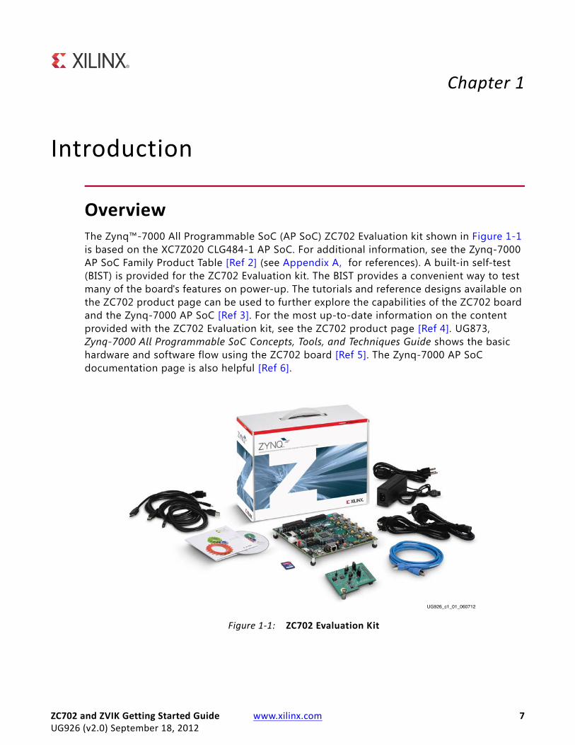
OverviewThe Zynq™-7000 All Programmable SoC (AP SoC) ZC702 Evaluation kit shown in Figure 1-1 is based on the XC7Z020 CLG484-1 AP SoC. For additional information, see the Zynq-7000 AP SoC Family Product Table [Ref 2] (see Appendix A, for references). A built-in self-test (BIST) is provided for the ZC702 Evaluation kit. The BIST provides a convenient way to test many of the board's features on power-up. The tutorials and reference designs available on the ZC702 product page can be used to further explore the capabilities of the ZC702 board and the Zynq-7000 AP SoC [Ref 3]. For the most up-to-date information on the content provided with the ZC702 Evaluation kit, see the ZC702 product page [Ref 4]. UG873, Zynq-7000 All Programmable SoC Concepts, Tools, and Techniques Guide shows the basic hardware and software flow using the ZC702 board [Ref 5]. The Zynq-7000 AP SoC documentation page is also helpful [Ref 6].
X-Ref Target - Figure 1-1
Figure 1-1: ZC702 Evaluation Kit
UG926_c1_01_060712
ZC702 and ZVIK Getting Started Guide www.xilinx.com 7UG926 (v2.0) September 18, 2012
Chapter 1: Introduction
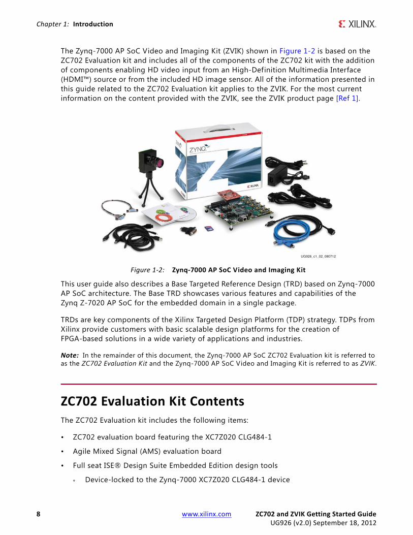
The Zynq-7000 AP SoC Video and Imaging Kit (ZVIK) shown in Figure 1-2 is based on the ZC702 Evaluation kit and includes all of the components of the ZC702 kit with the addition of components enabling HD video input from an High-Definition Multimedia Interface (HDMI™) source or from the included HD image sensor. All of the information presented in this guide related to the ZC702 Evaluation kit applies to the ZVIK. For the most current information on the content provided with the ZVIK, see the ZVIK product page [Ref 1].
This user guide also describes a Base Targeted Reference Design (TRD) based on Zynq-7000 AP SoC architecture. The Base TRD showcases various features and capabilities of the Zynq Z-7020 AP SoC for the embedded domain in a single package.
TRDs are key components of the Xilinx Targeted Design Platform (TDP) strategy. TDPs from Xilinx provide customers with basic scalable design platforms for the creation of FPGA-based solutions in a wide variety of applications and industries.
Note: In the remainder of this document, the Zynq-7000 AP SoC ZC702 Evaluation kit is referred to as the ZC702 Evaluation Kit and the Zynq-7000 AP SoC Video and Imaging Kit is referred to as ZVIK.
ZC702 Evaluation Kit ContentsThe ZC702 Evaluation kit includes the following items:
• ZC702 evaluation board featuring the XC7Z020 CLG484-1
• Agile Mixed Signal (AMS) evaluation board
• Full seat ISE® Design Suite Embedded Edition design tools
° Device-locked to the Zynq-7000 XC7Z020 CLG484-1 device
X-Ref Target - Figure 1-2
Figure 1-2: Zynq-7000 AP SoC Video and Imaging Kit
UG926_c1_02_080712
8 www.xilinx.com ZC702 and ZVIK Getting Started GuideUG926 (v2.0) September 18, 2012

ZC702 Evaluation Kit Contents
• Board design f iles
° Schematics
° Board layout f iles
° Bill of materials
• Documentation
° Getting Started Guide (this document)
° Hardware user guide (UG850, ZC702 Evaluation Board for the Zynq-7000 XC7Z020 All Programmable SoC User Guide [Ref 7])
° TRD user guide (UG925, Zynq-7000 All Programmable SoC ZC702 Base Targeted Reference Design User Guide [Ref 8])
• Reference Designs and Demonstrations
° BIST Utility and Demonstration
° Targeted Reference Design (TRD), demonstrating a video processing pipeline.
Note: The video demonstration contains the licensed IPs with no timeout. To recompile this design, the user needs to register for an evaluation IP license for the Video IP.
° AMS demonstration, providing an overview of the analog capabilities of the Zynq-7000 AP SoC devices.
• 12V AC adapter power supply
• Cables
° RJ-45 Ethernet cable
° HDMI cable
° USB Type-A to USB Micro-B cable (Digilent USB-to-JTAG Programing Port)
° USB Type-A to USB Mini-B cable (serial UART)
° USB Micro-B to female A adapter (for connecting USB hub, keyboard, and mouse)
• USB flash drive (contains reference design, documents, and board source f iles)
• Secure Digital Multimedia Card (SD MMC) (contains bootable configuration f iles for the Base TRD demonstration design files and Linux applications platform)
The kit contains the software and reference designs, a demonstration, and documents to help the user get started quickly.
ZC702 and ZVIK Getting Started Guide www.xilinx.com 9UG926 (v2.0) September 18, 2012

Chapter 1: Introduction
Zynq-7000 AP SoC Video and Imaging Kit ContentsThe ZVIK contains all of the items included in the ZC702 Evaluation kit plus the following items.
• HDMI input/output FPGA mezzanine card (FMC) module
• ON Semiconductor VITA 2000 Color Image Sensor module
• Standard interchangeable 2/3-inch 8 mm C-mount lens
• Infrared (IR) cut f ilter
• Camera tripod
• Lens holder
• Cables
° Second HDMI cable
° LCEDI image sensor cable
Key Features of the ZC702 Evaluation BoardKey features of the ZC702 evaluation board include:
• Zynq-7000 XC7Z020-1CLG484 device
• 1 GB DDR3 component memory (four 256 Mb x 8 devices)
• 128 Mb Quad SPI flash memory
• USB 2.0 ULPI (UTMI+ low pin interface) transceiver
• SD MMC connector
• USB JTAG interface through the Digilent USB-to-JTAG programing port
• Clock sources:
° Fixed user clock—(200 MHz) LVDS oscillator (differential)
° Programmable user clock—I2C programmable (10 MHz to 810 MHz, with a default setting of 156.250 MHz) LVDS oscillator (differential)
° Zynq processor reference clock—Fixed (33.33 MHz) LVCMOS oscillator (single-ended)
• Ethernet PHY RGMII interface with RJ-45 connector
• 10/100/1,000 tri-speed Ethernet PHY
10 www.xilinx.com ZC702 and ZVIK Getting Started GuideUG926 (v2.0) September 18, 2012

Key Features of the ZC702 Evaluation Board
• USB-to-UART bridge
• HDMI codec
• I2C bus
• I2C bus multiplexed to:
° Si570 user clock
° ADV7511 HDMI codec
° M24C08 EEPROM (1 KB)
° 1-to-16 TCA6416APWR port expander
° RTC-8564JE real-time clock
° FMC1 LPC I/O expansion connector
° FMC2 LPC I/O expansion connector
° PMBUS data/clock
• Status LEDs:
° Ethernet status
° Power good
° FPGA INIT
° FPGA DONE
• User I/O:
° Eight user LEDs
° Two user pushbuttons
° Two user switches (2-position DIP switches)
• CPU reset pushbutton
• Two VITA 57.1 FMC LPC connectors
• Power on/off slide switch
• Power management with PMBus voltage and current monitoring through TI power controllers
• XADC header with access to dual 12-bit 1 MSPS XADC port
• (SW1 – POR_B) boot configuration options:
° SD MMC Boot mode
° Quad SPI flash memory
° USB JTAG configuration port (Digilent module)
ZC702 and ZVIK Getting Started Guide www.xilinx.com 11UG926 (v2.0) September 18, 2012
Chapter 1: Introduction
° Platform cable header JTAG configuration port
For more detailed information about ZC702 board features, peripheral devices, and pinouts, see the hardware user guide UG850, ZC702 Evaluation Board for the Zynq-7000 XC7Z020 All Programmable SoC User Guide [Ref 7].
Key Features of the ZVIKKey features of the additional components of the Zynq-7000 AP SoC Video and Imaging kit include:
• HDMI input/output FMC module
° HDMI input
° HDMI output
° Video clock synthesizer
° Interface for ON Semiconductor VITA image sensor module
• ON Semiconductor VITA 2000 color image sensor module
° Supports up to WXGA resolution: 1920 (H) x 1200 (V) format
° 92 frames per second (fps) at full resolution
° 4.8 μm x 4.8 μm pixel size 2/3-inch optical format
° Pipelined and triggered global shutter, rolling shutter
° Random programmable region of interest (ROI) readout
° Automatic exposure control (AEC)
• Standard interchangeable 2/3-inch, 8 mm C-mount lens
12 www.xilinx.com ZC702 and ZVIK Getting Started GuideUG926 (v2.0) September 18, 2012

Default Jumper and Switch Settings
Default Jumper and Switch SettingsFigure 1-3 calls out the major features on the ZC702 board. See UG850, ZC702 Evaluation Board for the Zynq-7000 XC7Z020 All Programmable SoC User Guide [Ref 7] for more detailed information about the ZC702 board.
Default factory settings of jumpers and switches on the ZC702 board are highlighted in Figure 1-4. Default switch and jumper settings are listed in Table 1-1 and Table 1-2.
X-Ref Target - Figure 1-3
Figure 1-3: Feature Callout for the ZC702 Board
FMC1 LPCConnector
Xilinx XADCHeader
UG926_c1_03_081412
FMC2 LPCConnector
8 User LEDs
User 2-Pole DIP Switch
Zynq-7000 AP SoC
Power Management System(Bottom and Top of Board)
FPGA PROG Pushbutton
I2C Real-time Clock (RTC)
DDR3 ComponentMemory (1 GB)
RGMII EthernetPHY Oscillator,25,000 MHz
Quad SPI Flash Memory (1 Gb)
SD Card Interface Connector
Configuration ModeSelect Switch
System Clock, 200 MHz,2.5V LVDS
I2C Bus Switch
Power On/Off Slide Switch
CAN Bus Transceiver
HDMI Controller,HDMI Video Connector
USB JTAGModule with IntegratedUSB Mini-B Connector
I2C Programmable UserClock 3.3V LVDS
User PushbuttonsActive High
Ethernet StatusLEDs
USB-to-UART Bridge,USB Mini-B Connector
2x6 Male Header Pins I/O Driven fromI2C Expander U80
USB 2.0 ULPITransceiver,USB Micro-B
Connector
10/100/1000 MHzEthernet PHY,
RJ45 with Magnetics
2x6 and 1x6PMOD I/O Header
ZC702 and ZVIK Getting Started Guide www.xilinx.com 13UG926 (v2.0) September 18, 2012

Chapter 1: Introduction
X-Ref Target - Figure 1-4
Figure 1-4: Default Jumper and Switch Settings on the ZC702 Board
UG926_c1_04_073112
1
8
9
7
SW11Down/Off
2
3
4
6 5
14 www.xilinx.com ZC702 and ZVIK Getting Started GuideUG926 (v2.0) September 18, 2012

Default Jumper and Switch Settings
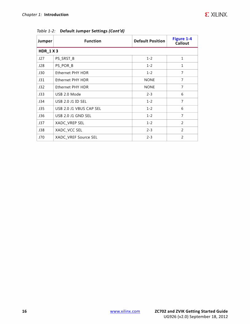
Default jumper positions are shown in Figure 1-4 and listed in Table 1-2.
Table 1-1: Default Switch Settings
Switch Position Setting Figure 1-4 Callout
SW10(JTAG chain input select two-position DIP switch)
1 Off9
2 On
SW12(two-position DIP switch)
1 Off2
2 Off
SW15(two-position DIP switch)
1 Off2
2 Off
SW16(five-position DIP switch)
1 Right
1
2 Right
3 Right
4 Right
5 Right
SW11(power slide switch)
Off8
1 Down
Table 1-2: Default Jumper Settings
Jumper Function Default Position Figure 1-4 Callout
HDR_1 X 2
J5 CFGBVS short to GND OFF 4
J6 POR Master Reset OFF 1
J7 USB 2.0 USB_VBUS_SEL ON 6
J8 XADC GND L3 Bypass OFF 2
J9 XADC GND ON 2
J10 ARM HDR J41 pin 2 to VADJ OFF 7
J11 UCD9248 U32 ADDR52 RESET_B OFF 4
J12 FMC_VADJ_ON_B ON 4
J13 UCD9248 U33 ADDR53 RESET_B OFF 3
J14 UCD9248 U34 ADDR54 RESET_B OFF 5
J15 CAN BUS COMMON-MODE CANH HDR ON 7
J43 Ethernet PHY HDR ON 7
J44 USB 2.0 USB_RESET_B OFF 7
J53 CAN BUS COMMON-MODE CANL HDR ON 7
J56 JTAG HDR J58 pin 2 3.3V SEL OFF 9
J65 XADC_VCC5V0 = VCC5V0 OFF 2
ZC702 and ZVIK Getting Started Guide www.xilinx.com 15UG926 (v2.0) September 18, 2012
Chapter 1: Introduction
HDR_1 X 3
J27 PS_SRST_B 1-2 1
J28 PS_POR_B 1-2 1
J30 Ethernet PHY HDR 1-2 7
J31 Ethernet PHY HDR NONE 7
J32 Ethernet PHY HDR NONE 7
J33 USB 2.0 Mode 2-3 6
J34 USB 2.0 J1 ID SEL 1-2 7
J35 USB 2.0 J1 VBUS CAP SEL 1-2 6
J36 USB 2.0 J1 GND SEL 1-2 7
J37 XADC_VREP SEL 1-2 2
J38 XADC_VCC SEL 2-3 2
J70 XADC_VREF Source SEL 2-3 2
Table 1-2: Default Jumper Settings (Cont’d)
Jumper Function Default Position Figure 1-4 Callout
16 www.xilinx.com ZC702 and ZVIK Getting Started GuideUG926 (v2.0) September 18, 2012

Chapter 2
ZC702 Evaluation Kit Built-In Self-Test
IntroductionThe BIST tests many of the features offered by the ZC702 Evaluation kit. The test is stored in the onboard nonvolatile Quad SPI flash memory and configures the AP SoC when mode switch SW16 is set to where SW1, 2, 3, and 5 are switched to the right and SW4 is switched to the left, indicating QSPI configuration. This exercise of running the BIST demonstration should take approximately 10 to 15 minutes.
Note: For a description of all the features on the ZC702 board, see UG850, ZC702 Evaluation Board for the Zynq-7000 XC7Z020 All Programmable SoC User Guide [Ref 7].
BIST Setup RequirementsThese are the prerequisites for running the BIST demonstration.
• Hardware setup:
° ZC702 evaluation board with XC7Z020 CLG484-1 part
- A power adapter and power cable for the ZC702 board
° USB Type-A to Mini-B cable (for UART)
° AC power adapter (12 VDC)
• Windows software and driver setup:
° TeraTerm Pro [Ref 9] (or similar) terminal program (might already be installed)
° USB-UART driver from Silicon Labs [Ref 10] (might already be installed)
ZC702 and ZVIK Getting Started Guide www.xilinx.com 17UG926 (v2.0) September 18, 2012
Chapter 2: ZC702 Evaluation Kit Built-In Self-Test
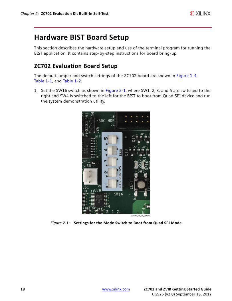
Hardware BIST Board SetupThis section describes the hardware setup and use of the terminal program for running the BIST application. It contains step-by-step instructions for board bring-up.
ZC702 Evaluation Board SetupThe default jumper and switch settings of the ZC702 board are shown in Figure 1-4, Table 1-1, and Table 1-2.
1. Set the SW16 switch as shown in Figure 2-1, where SW1, 2, 3, and 5 are switched to the right and SW4 is switched to the left for the BIST to boot from Quad SPI device and run the system demonstration utility.
X-Ref Target - Figure 2-1
Figure 2-1: Settings for the Mode Switch to Boot from Quad SPI Mode
UG926_c2_01_061212
18 www.xilinx.com ZC702 and ZVIK Getting Started GuideUG926 (v2.0) September 18, 2012

Hardware Bring-Up
Hardware Bring-UpThis section describes the steps for hardware bring-up.
1. Be sure to have the SW16 Mode switch settings set to those shown in Figure 2-1.
2. With the ZC702 board switched OFF (SW11 in the down position, as shown in Figure 1-4), plug the USB Mini-B cable into the Mini USB port J17 labeled USB UART on the ZC702 board and the other end into a open USB port on your PC (see Figure 2-2).
3. Connect the power cable.
4. Switch the ZC702 board’s power to ON (SW11 switched up as shown in Figure 1-4).
X-Ref Target - Figure 2-2
Figure 2-2: ZC702 with the UART and Power Cable Attached
UG926_c2_02_080212
USB/UART
12V Power
Init LED
ZC702 and ZVIK Getting Started Guide www.xilinx.com 19UG926 (v2.0) September 18, 2012

Chapter 2: ZC702 Evaluation Kit Built-In Self-Test
Install the USB-UART Driver1. Run the downloaded executable UART-USB driver f ile, listed in BIST Setup Requirements,
page 17. Running the executable f ile enables USB-to-UART communications with a host PC.
2. Set the USB-UART connection to a known COM Port and baud rate in the Device Manager.
a. Right-click My Computer and select Properties.
b. Select Device Manager on the left side. (On Windows XP, select the Hardware tab and then the Device Manager button.
c. Right-click the Silicon Labs device in the list and select Properties.
d. Click the Port Settings tab. Click the Advanced… button.
e. Select an open COM port between COM1 and COM4. This allows the computer to remember the assignment and not reassign it each time the board serial UART port is plugged in.
X-Ref Target - Figure 2-3
Figure 2-3: UART Cable Driver Installation
UG926_c2_03_061212
20 www.xilinx.com ZC702 and ZVIK Getting Started GuideUG926 (v2.0) September 18, 2012

Hardware Bring-Up
f. Select the baud rate = 115200, Data bits = 8, Parity = None, Stop Bits = 1, and Flow control = None. Click OK.
Note: Steps and diagrams refer to using a Windows XP or Windows 7 host PC.
Figure 2-4 through Figure 2-6 show the steps for setting the USB-UART port.
X-Ref Target - Figure 2-4
Figure 2-4: Configuring the Driver
UG926_c2_04_061212
ZC702 and ZVIK Getting Started Guide www.xilinx.com 21UG926 (v2.0) September 18, 2012

Chapter 2: ZC702 Evaluation Kit Built-In Self-Test
X-Ref Target - Figure 2-5
Figure 2-5: UART Port Setting Tab
UG926_c2_05_061212
22 www.xilinx.com ZC702 and ZVIK Getting Started GuideUG926 (v2.0) September 18, 2012

Hardware Bring-Up
X-Ref Target - Figure 2-6
Figure 2-6: Select a COM Port (between COM1 and COM4)
UG926_c2_06_061212
ZC702 and ZVIK Getting Started Guide www.xilinx.com 23UG926 (v2.0) September 18, 2012

Chapter 2: ZC702 Evaluation Kit Built-In Self-Test
Run the BIST Application1. Start Tera Term or a comparable installed terminal program. Configure it to have the
following settings:Baud = 115200, Data = 8, P = None, Stop = 1 and Flow = None.
2. Press POR_B (SW1) located in the top left corner of the ZC702 board and view the BIST output on the terminal window (see Figure 2-7).
3. Select each relevant test and observe the test results.
For more information on the BIST software and additional tutorials, including how to restore the default content of the onboard Quad SPI flash nonvolatile storage, see the ZC702 resource page [Ref 4].
For more detailed information about these BIST tests, refer to UG850, ZC702 Evaluation Board for the Zynq-7000 XC7Z020 All Programmable SoC User Guide [Ref 7]. Also refer to the ZC702 BIST User Guide found in the Docs & Designs tab on www.xilinx.com/zc702 [Ref 4] i.e., the ZC702 BIST PDF file, XTP180.
X-Ref Target - Figure 2-7
Figure 2-7: BIST Main Menu
UG926_c2_07_061412
24 www.xilinx.com ZC702 and ZVIK Getting Started GuideUG926 (v2.0) September 18, 2012
Run the BIST Application
If any of the BIST tests fail, check the settings of the switches and jumpers as shown in Figure 1-4, Table 1-1, and Table 1-2. If these settings are correct and the test still fails, please contact Xilinx Support and open a WebCase.
ZC702 and ZVIK Getting Started Guide www.xilinx.com 25UG926 (v2.0) September 18, 2012

Chapter 2: ZC702 Evaluation Kit Built-In Self-Test
26 www.xilinx.com ZC702 and ZVIK Getting Started GuideUG926 (v2.0) September 18, 2012

Chapter 3
Getting Started with the Base Targeted Reference Design
IntroductionFigure 3-1 shows the system block diagram for Zynq-7000 AP SoC Base TRD.
X-Ref Target - Figure 3-1
Figure 3-1: Zynq-7000 AP SoC ZC702 and ZVIK Base TRD System Block Diagram
Linux User Space
Linux Kernel
ProcessingSystem
Qt-Based Multithreaded Application
Kernel Libraries and Utilities Device Drivers
DDR Memory Controller
ProgrammableLogic
Display Controller
Video Test PatternGenerator
VideoOutput
UG926_c3_01_080812
S_AXI3_HP 64 bit
M_AXI3_GP 32 bit
Video Processing(Sobel Filter)APU
AMBA Switches
AMBA Switches
(Optional) Video Input with Zynq-7000 Video andImaging Kit
ZC702 and ZVIK Getting Started Guide www.xilinx.com 27UG926 (v2.0) September 18, 2012
Chapter 3: Getting Started with the Base Targeted Reference Design
The Base TRD showcases various features and capabilities of the Zynq Z-7020 AP SoC for the embedded domain in a single package. The Base TRD consists of two processing elements: The Zynq-7000 AP SoC processing system (PS) and an interconnect logic-based video accelerator. The AP SoC allows the user to implement a specif ic functionality either as a software program running on the Zynq-7000 AP SoC PS or as a hardware design inside the programmable logic (PL). The Base TRD demonstrates how the user can seamlessly switch between a software or a hardware implementation, contributing to ease of use. The TRD also demonstrates the value of offloading computation-intensive tasks onto PL, thereby freeing the CPU resources to be available for user-specif ic applications.
This section of the document provides step by step instructions for bringing up the board and for running a video demonstration out of the box.
The ZC702 Evaluation kit and ZVIK come with an SD card loaded with binaries that enable the user to run the video demonstration and software application. It also includes the binaries necessary to configure and boot the Zynq-7000 AP SoC board.
Note: The screen captures in this document are conceptual representations of their subjects and provide general information only.
Base TRD Key FeaturesThe PS includes:
• Two ARM Cortex-A9 MPcore processors, each with a 32 KB instruction cache, a 32 KB data cache, and a NEON™ media processing engine and vector floating-point processor (VFPv3).
• 512 KB of level 2 cache
• 256 KB of on-chip RAM
• ARM AMBA® AXI interconnect
• Multi-protocol, 32-bit DDR DRAM controller
• 1 GB DDR3 running at 533 MHz
• Standard peripheral interfaces including USB, Ethernet, UART, I2C, SD MMC, and GPIO
• Clocks and reset for PL
• High bandwidth interconnect between PS and PL
The PL includes:
• Two AXI interconnects, 64-bit wide at 150 MHz
• One AXI interconnect, 32-bit wide at 75 MHz
28 www.xilinx.com ZC702 and ZVIK Getting Started GuideUG926 (v2.0) September 18, 2012
Base TRD Hardware Setup Requirements
• AXI VDMA(s)
• A full HD video input (ZVIK) and output interface
• A Sobel accelerator
• Two AXI Performance Monitors
The software includes:
• Xilinx Zynq-7000 AP SoC standard Linux kernel (based on Open Source Linux version 3.x)
• Linux device drivers for TRD-specif ic IPs.
• A Qt-based Linux application demonstrating the video processing pipeline
• A command line menu-based Linux application demonstrating the video processing pipeline
Note: The video demonstration contains the licensed IPs with no timeout.
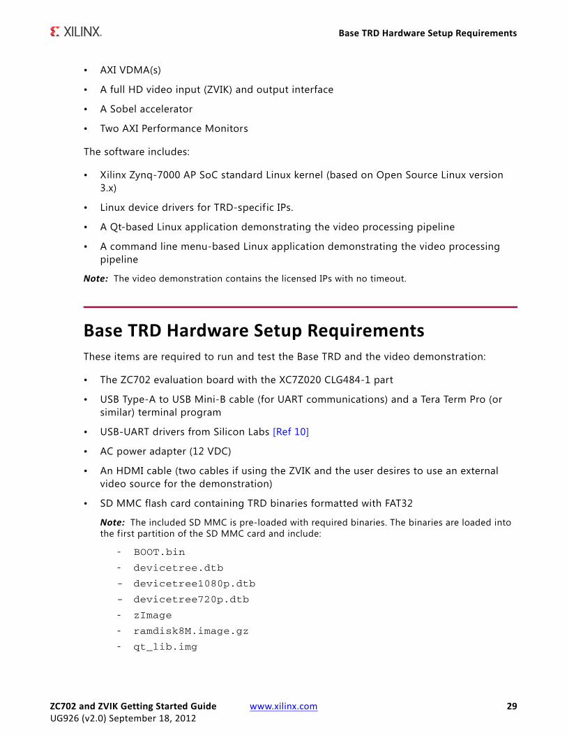
Base TRD Hardware Setup RequirementsThese items are required to run and test the Base TRD and the video demonstration:
• The ZC702 evaluation board with the XC7Z020 CLG484-1 part
• USB Type-A to USB Mini-B cable (for UART communications) and a Tera Term Pro (or similar) terminal program
• USB-UART drivers from Silicon Labs [Ref 10]
• AC power adapter (12 VDC)
• An HDMI cable (two cables if using the ZVIK and the user desires to use an external video source for the demonstration)
• SD MMC flash card containing TRD binaries formatted with FAT32
Note: The included SD MMC is pre-loaded with required binaries. The binaries are loaded into the f irst partition of the SD MMC card and include:
- BOOT.bin
- devicetree.dtb
- devicetree1080p.dtb
- devicetree720p.dtb
- zImage
- ramdisk8M.image.gz
- qt_lib.img
ZC702 and ZVIK Getting Started Guide www.xilinx.com 29UG926 (v2.0) September 18, 2012

Chapter 3: Getting Started with the Base Targeted Reference Design
- init.sh
- run_sobel.sh
- sobel_cmd
- sobel_qt
- zynq.png
Note: The default binary device tree devicetree.dtb is for configuring the video-out resolution to 1080p. Additionally, the binaries should be loaded at its root level. If the f iles are not loaded on the SD MMC, copy the f iles from the sd_image directory to the SD MMC.
• USB Micro-B to female A adapter
• A USB hub is needed for connecting a keyboard and mouse (not included with the kit). If a USB hub is not available, it is still possible to run the demonstration, but the user will not be able to exercise the portions of the demonstration that require a keyboard.
• USB mouse and keyboard (not included with the kit)
• An HDMI-compatible display monitor that supports full HD resolution: 1920 x 1080p @ 60 Hz (not included with the kit). If the user wants to test at 720p video resolution, the display monitor should support 720p resolution: 1280 x 720p @ 60 Hz. If an HDMI monitor is not available, a DVI monitor can be used, but an HDMI to DVI-D cable/connector adapter is required (not included with the kit). The connector adapter can be easily obtained at most electronic retailers or through a variety of online sources.
Note: The example mentioned in this package has been tested with a Dell model #P2412H display monitor. However, the example should work well with any HDMI-compatible display device.
• For the ZVIK, if running with an external video input source is desired, use the FMC-IMAGEON HDMI input/output FMC module to connect an external video source. An HDMI video source is required to provide the external video input. If an HDMI source is not available, a DVI source can be used, but an HDMI to DVI-D cable/connector adapter is required (not included with the kit). The connector adapter can be easily obtained at most electronic retailers or through a variety of online sources.
Note: This TRD does not support input from the camera provided in the ZVIK.
30 www.xilinx.com ZC702 and ZVIK Getting Started GuideUG926 (v2.0) September 18, 2012
TRD Demonstration Procedure
TRD Demonstration ProcedureThis section provides a procedure for setting up the ZC702 board or ZVIK and running the demonstration provided with the kit.
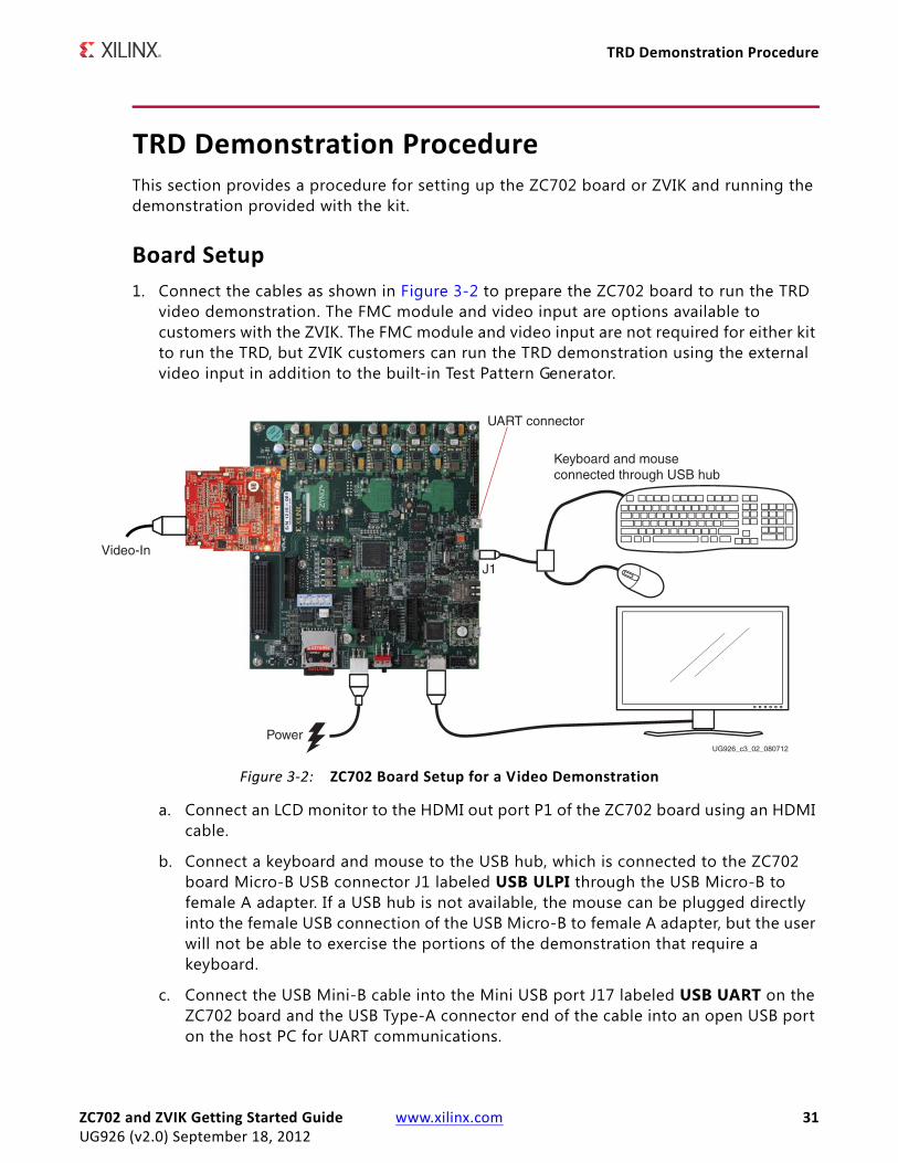
Board Setup1. Connect the cables as shown in Figure 3-2 to prepare the ZC702 board to run the TRD
video demonstration. The FMC module and video input are options available to customers with the ZVIK. The FMC module and video input are not required for either kit to run the TRD, but ZVIK customers can run the TRD demonstration using the external video input in addition to the built-in Test Pattern Generator.
a. Connect an LCD monitor to the HDMI out port P1 of the ZC702 board using an HDMI cable.
b. Connect a keyboard and mouse to the USB hub, which is connected to the ZC702 board Micro-B USB connector J1 labeled USB ULPI through the USB Micro-B to female A adapter. If a USB hub is not available, the mouse can be plugged directly into the female USB connection of the USB Micro-B to female A adapter, but the user will not be able to exercise the portions of the demonstration that require a keyboard.
c. Connect the USB Mini-B cable into the Mini USB port J17 labeled USB UART on the ZC702 board and the USB Type-A connector end of the cable into an open USB port on the host PC for UART communications.
X-Ref Target - Figure 3-2
Figure 3-2: ZC702 Board Setup for a Video Demonstration
Keyboard and mouseconnected through USB hub
Video-In
PowerUG926_c3_02_080712
UART connector
J1
ZC702 and ZVIK Getting Started Guide www.xilinx.com 31UG926 (v2.0) September 18, 2012

Chapter 3: Getting Started with the Base Targeted Reference Design
d. If using the ZVIK, mount the FMC-IMAGEON HDMI input/output FMC module onto the FMC-2 slot present on the ZC702 board. Attach the FMC board to the ZC702 carrier board using the standoffs and four screws included in the kit. Connect an external video source to the FMC module HDMI input labeled HDMI IN with 1080p60 resolution. A 720p60 source can also be used, but it requires adjustment to the system as described in the section Running the Video Demonstration for 720p Video Resolution, page 38.
e. Connect the power supply to the ZC702 board connector J60. Do not switch the power on.
2. Insert the SD MMC, which contains the TRD binaries, into the SD slot on the ZC702 board.
° Ensure the binary f iles are in the f irst partition of the FAT32-formatted SD MMC card at its root level.
Note: If the evaluation kit design f iles were downloaded online, copy all the f iles within the zynq_base_trd_14.x/sd_image folder directly onto the primary partition of the SD MMC card (which is formatted as FAT32) at the root level using an SD MMC card reader. The f iles in the SD MMC card should match the list described in SD MMC flash card containing TRD binaries formatted with FAT32, page 29.
3. Make sure the switches are set as shown in Figure 3-3, which allows the ZC702 board to boot from the SD MMC card.
4. Make sure the display monitor is set for HDMI or DVI 1920 x 1080.
X-Ref Target - Figure 3-3
Figure 3-3: Switch Settings for the Mode Switch to Boot from the SD MMC Card
UG926_c3_03_061412
32 www.xilinx.com ZC702 and ZVIK Getting Started GuideUG926 (v2.0) September 18, 2012
Running the Qt-Based GUI Application Demonstration
Running the Qt-Based GUI Application Demonstration1. Power on the ZC702 board. The default binary Linux device tree (devicetree.dtb)
configures and runs the video demonstration for 1080p video-out resolution.
2. Start the installed UART terminal program on your host PC (e.g., Tera Term Pro on a Windows PC, GtkTerm on a Linux PC).
Use the following UART configuration: Baud rate = 115200, bits = 8, parity = none, and stop bits = 1.
Note: This step is required to view debug information or to run the UART Menu-Based Demonstration application.
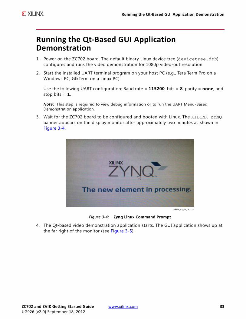
3. Wait for the ZC702 board to be configured and booted with Linux. The XILINX ZYNQ banner appears on the display monitor after approximately two minutes as shown in Figure 3-4.
4. The Qt-based video demonstration application starts. The GUI application shows up at the far right of the monitor (see Figure 3-5).
X-Ref Target - Figure 3-4
Figure 3-4: Zynq Linux Command Prompt
UG926_c3_04_061212
ZC702 and ZVIK Getting Started Guide www.xilinx.com 33UG926 (v2.0) September 18, 2012

Chapter 3: Getting Started with the Base Targeted Reference Design
5. The Qt-based application allows the user to experience the Base TRD video demonstration and is controlled through the mouse. The Qt application window automatically disappears when not in use, but can be re-activated by moving the mouse. To prevent the window from disappearing, the user can click Pushpin, which will pin down the control console so that it will not disappear regardless of the mouse position. The user can click Help for short messages and information about the control window of the QT application.
X-Ref Target - Figure 3-5
Figure 3-5: Qt-Based GUI to Control the Video Pipeline
UG926_c3_05_080612
34 www.xilinx.com ZC702 and ZVIK Getting Started GuideUG926 (v2.0) September 18, 2012

Running the Qt-Based GUI Application Demonstration
6. Click Enable Video to start the internal Test Pattern Generator (TPG), which displays on the monitor.
7. Exercise different options by pressing the buttons available in the GUI to evaluate the different use cases mentioned in Table 3-1.
Video source control modes are explained as follows:
• TPG interference
° The input video is generated by the TPG IP implemented in the PL.
• External video (available with the optional ZVIK FMC module)
° The input video is supplied by an external video source and is connected through the FMC-IMAGEON card.
Sobel Filter Modes are explained as follows:
Sobel OFF
• No processing done. Sobel f ilter is bypassed.
Sobel – SW
• Video processing (edge-detection f ilter) done by software code running on the PS.
• Observe CPU utilization going up to 100% for one of the two CPUs (this can be seen in the CPU usage graph). In this mode, the frame rate of the video also drops to about 10 fps.
Sobel – HW
• Video processing (edge-detection f iltering) done by PL.
• Observe CPU utilization going down (to approximately 0) and the frame rate jumping to 60 fps.
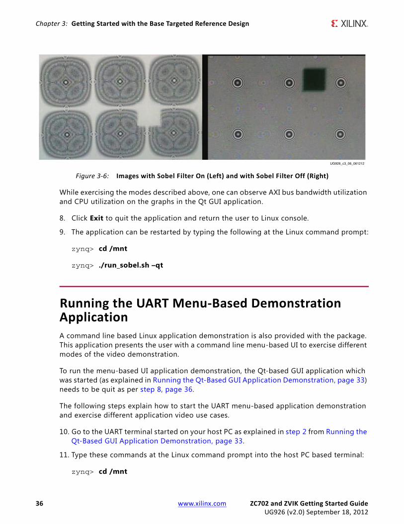
Figure 3-6 shows the detected image edges of the video generated by the TPG, that is, case 1 versus case 2 or 3 of Table 3-1.
Table 3-1: Zynq-7000 AP SoC Base TRD Video Demonstration Use Cases
Use Case Video Source Control Sobel Filter Control
1 TPG interference Sobel OFF
2 TPG interference Sobel - SW
3 TPG interference Sobel - HW
Additional ZVIK Options
4 External video Sobel OFF
5 External video Sobel - SW
6 External video Sobel - HW
ZC702 and ZVIK Getting Started Guide www.xilinx.com 35UG926 (v2.0) September 18, 2012
Chapter 3: Getting Started with the Base Targeted Reference Design
While exercising the modes described above, one can observe AXI bus bandwidth utilization and CPU utilization on the graphs in the Qt GUI application.
8. Click Exit to quit the application and return the user to Linux console.
9. The application can be restarted by typing the following at the Linux command prompt:
zynq> cd /mnt
zynq> ./run_sobel.sh –qt
Running the UART Menu-Based Demonstration ApplicationA command line based Linux application demonstration is also provided with the package. This application presents the user with a command line menu-based UI to exercise different modes of the video demonstration.
To run the menu-based UI application demonstration, the Qt-based GUI application which was started (as explained in Running the Qt-Based GUI Application Demonstration, page 33) needs to be quit as per step 8, page 36.
The following steps explain how to start the UART menu-based application demonstration and exercise different application video use cases.
10. Go to the UART terminal started on your host PC as explained in step 2 from Running the Qt-Based GUI Application Demonstration, page 33.
11. Type these commands at the Linux command prompt into the host PC based terminal:
zynq> cd /mnt
X-Ref Target - Figure 3-6
Figure 3-6: Images with Sobel Filter On (Left) and with Sobel Filter Off (Right)
UG926_c3_06_061212
36 www.xilinx.com ZC702 and ZVIK Getting Started GuideUG926 (v2.0) September 18, 2012
Running the UART Menu-Based Demonstration Application
zynq> ./run_sobel.sh –cmd
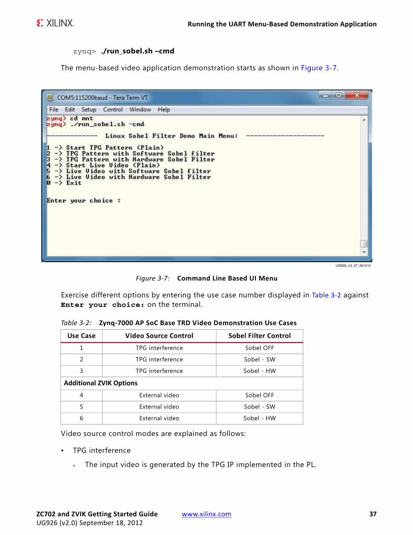
The menu-based video application demonstration starts as shown in Figure 3-7.
Exercise different options by entering the use case number displayed in Table 3-2 against Enter your choice: on the terminal.
Video source control modes are explained as follows:
• TPG interference
° The input video is generated by the TPG IP implemented in the PL.
X-Ref Target - Figure 3-7
Figure 3-7: Command Line Based UI Menu
UG926_c3_07_061212
Table 3-2: Zynq-7000 AP SoC Base TRD Video Demonstration Use Cases
Use Case Video Source Control Sobel Filter Control
1 TPG interference Sobel OFF
2 TPG interference Sobel - SW
3 TPG interference Sobel - HW
Additional ZVIK Options
4 External video Sobel OFF
5 External video Sobel - SW
6 External video Sobel - HW
ZC702 and ZVIK Getting Started Guide www.xilinx.com 37UG926 (v2.0) September 18, 2012

Chapter 3: Getting Started with the Base Targeted Reference Design
• External video (available with the optional ZVIK FMC module)
° The input video is supplied by an external video source and is connected through the FMC-IMAGEON card.
Sobel Filter Modes are explained as follows:
Sobel OFF
• No processing done. Sobel f ilter is bypassed.
Sobel – SW
• Video processing (edge-detection f ilter) done by software code running on PS
Sobel On – HW
• Video processing (edge-detection f ilter) done by PL
Figure 3-6 shows the detected image edges of the video generated by the TPG, that is, case 1 versus case 2 or 3 of Table 3-2.
12. Enter 0 to exit the application and return to the command prompt.
Running the Video Demonstration for 720p Video ResolutionCopy the devicetree720p.dtb binary f ile (provided with the binary package) and save it as devicetree.dtb in the SD MMC root, overwriting the old devicetree.dtb. Configure the display monitor to 720p60 resolution: 1280 x 720p @ 60 Hz. If using the ZVIK with an external video source, configure the external video source to 1280 x 720 @ 60 Hz.
Note: To restore the design to support 1080P60 again, copy the f ile devicetree1080P.dtb and save it as devicetree.dtb on the SD MMC root, overwriting the old devicetree.dtb.
• Follow the steps in Running the Qt-Based GUI Application Demonstration, page 33 to run the Qt-based GUI application demonstration.
• Follow the steps in Running the UART Menu-Based Demonstration Application, page 36 to run the menu-based application demonstration.
38 www.xilinx.com ZC702 and ZVIK Getting Started GuideUG926 (v2.0) September 18, 2012
Chapter 4
Using the AMS101 Evaluation Card
IntroductionEach Xilinx Zynq-7000 AP SoC features two 1 MSPS, 12-bit, analog-to-digital converters (ADCs) built into the device for everything from simple analog monitoring to more signal processing-intensive tasks like linearization, calibration, over-sampling, and f iltering. The ZC702 Evaluation kit includes the hardware and software to evaluate this ADC feature and to determine its usefulness in the user’s end system.
For evaluation of Xilinx Agile Mixed Signal (AMS) capability, the following items in the kit are needed:
• Access to the ZC702 XADC header
• AMS101 evaluation card (see Figure 4-1)
• Design and software files, included on the USB key or downloaded from the web
• FPGA design programming f iles
• USB-UART drivers from Silicon Labs
• Blank SD MMC card
ZC702 and ZVIK Getting Started Guide www.xilinx.com 39UG926 (v2.0) September 18, 2012
Chapter 4: Using the AMS101 Evaluation Card
Requirements to Get Started1. The AMS101 evaluation requires a Windows host PC to install the National Instruments
LabVIEW Run-Time engine.
2. Verify the USB/UART Silicon Labs drivers are installed as described in Install the USB-UART Driver, page 20.
3. Depending on the computer operating system, select and install one of these National Instruments LabVIEW 2011 Run-Time Engine AMS101 Installers for a 32-bit OS or a 64-bit OS:
a. LabVIEW 32-bit Run-Time Engine:joule.ni.com/nidu/cds/view/p/id/2534/lang/en
b. LabVIEW 64-bit Run-Time Enginejoule.ni.com/nidu/cds/view/p/id/2536/lang/en
4. Unzip the AMS_Eval_Demo_Files_<ISE_Version> from the ZC702_Reference_Designs folder on the USB stick to access the AMS bitstream (boot.bin).
5. Copy the boot.bin f ile on an SD MMC card.
X-Ref Target - Figure 4-1
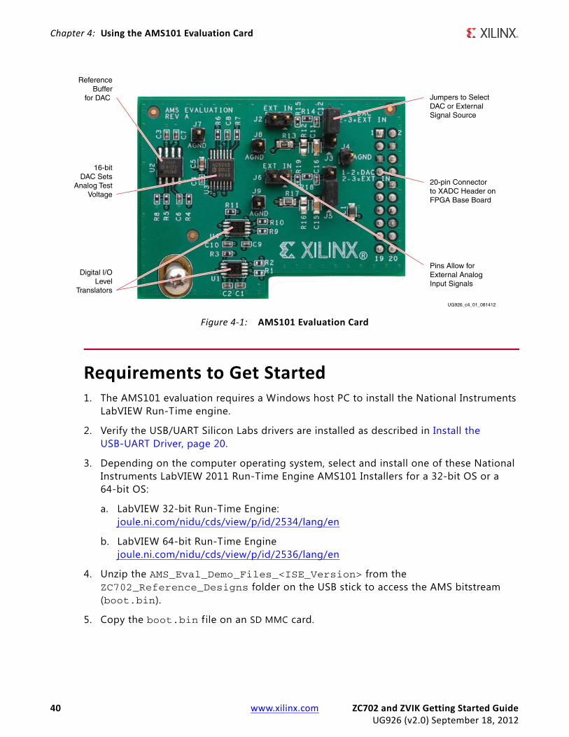
Figure 4-1: AMS101 Evaluation Card
ReferenceBuffer
for DAC Jumpers to SelectDAC or ExternalSignal Source
20-pin Connectorto XADC Header onFPGA Base Board
Pins Allow forExternal AnalogInput Signals
16-bitDAC Sets
Analog TestVoltage
Digital I/OLevel
Translators
UG926_c4_01_081412
40 www.xilinx.com ZC702 and ZVIK Getting Started GuideUG926 (v2.0) September 18, 2012
Evaluating AMS
Evaluating AMS1. Connect and power the hardware.
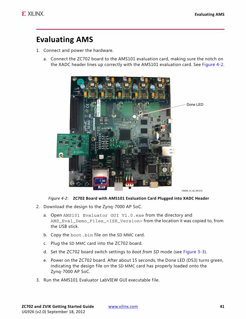
a. Connect the ZC702 board to the AMS101 evaluation card, making sure the notch on the XADC header lines up correctly with the AMS101 evaluation card. See Figure 4-2.
2. Download the design to the Zynq-7000 AP SoC.
a. Open AMS101 Evaluator GUI V1.0.exe from the directory and AMS_Eval_Demo_Files_<ISE_Version> from the location it was copied to, from the USB stick.
b. Copy the boot.bin f ile on the SD MMC card.
c. Plug the SD MMC card into the ZC702 board.
d. Set the ZC702 board switch settings to boot from SD mode (see Figure 3-3).
e. Power on the ZC702 board. After about 15 seconds, the Done LED (DS3) turns green, indicating the design file on the SD MMC card has properly loaded onto the Zynq-7000 AP SoC.
3. Run the AMS101 Evaluator LabVIEW GUI executable f ile.
X-Ref Target - Figure 4-2
Figure 4-2: ZC702 Board with AMS101 Evaluation Card Plugged into XADC Header
UG926_c4_02_061212
Done LED
ZC702 and ZVIK Getting Started Guide www.xilinx.com 41UG926 (v2.0) September 18, 2012
Chapter 4: Using the AMS101 Evaluation Card
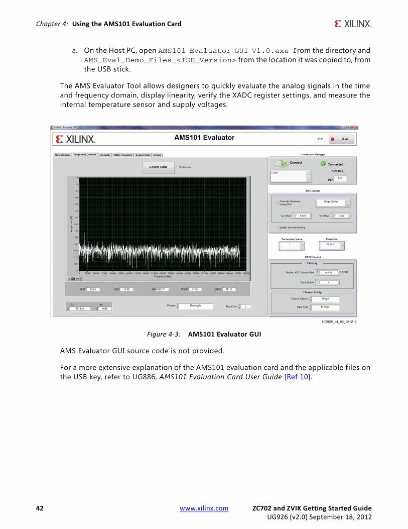
a. On the Host PC, open AMS101 Evaluator GUI V1.0.exe from the directory and AMS_Eval_Demo_Files_<ISE_Version> from the location it was copied to, from the USB stick.
The AMS Evaluator Tool allows designers to quickly evaluate the analog signals in the time and frequency domain, display linearity, verify the XADC register settings, and measure the internal temperature sensor and supply voltages.
AMS Evaluator GUI source code is not provided.
For a more extensive explanation of the AMS101 evaluation card and the applicable f iles on the USB key, refer to UG886, AMS101 Evaluation Card User Guide [Ref 10].
X-Ref Target - Figure 4-3
Figure 4-3: AMS101 Evaluator GUI
UG926_c4_03_061212
42 www.xilinx.com ZC702 and ZVIK Getting Started GuideUG926 (v2.0) September 18, 2012

Next Steps
Next StepsFor more information on reference designs included in this kit, software, and additional tutorials, including how to restore the default content of the onboard nonvolatile storage, see the ZC702 product page [Ref 4].
Next Steps for the Zynq-7000 AP SoC Video and Imaging Kit (ZVIK)For more information on reference designs, tutorials, software, and other information available for the ZVIK, see the Zynq-7000 All Programmable SoC Video and Imaging Kit product page [Ref 1].
ZC702 and ZVIK Getting Started Guide www.xilinx.com 43UG926 (v2.0) September 18, 2012

Chapter 4: Using the AMS101 Evaluation Card
44 www.xilinx.com ZC702 and ZVIK Getting Started GuideUG926 (v2.0) September 18, 2012

Appendix A
Additional Resources
Xilinx ResourcesTo search the Answer database of silicon, software, and IP questions and answers, or to create a technical support WebCase, see the Xilinx Support website at:www.xilinx.com/support
For a glossary of technical terms used in Xilinx documentation, see:www.xilinx.com/company/terms.htm
To find additional documentation, see the Xilinx website at:www.xilinx.com/support/documentation/index.htm
For a comprehensive listing of Video and Imaging application notes, white papers, reference designs, and related IP cores, see the Video and Imaging Resources page atwww.xilinx.com/esp/video/refdes_listing.htm#ref_des
ReferencesThese documents provide supplemental material useful with this guide:
1. Zynq-7000 All Programmable SoC Video and Imaging Kit product pagewww.xilinx.com/zvik
2. Zynq-7000 All Programmable SoC Product Tablewww.xilinx.com/publications/prod_mktg/zynq7000/Zynq-7000-combined-product-table.pdf
3. Zynq-7000 All Programmable SoC pagewww.xilinx.com/products/silicon-devices/epp/zynq-7000
4. Xilinx Zynq-7000 All Programmable SoC ZC702 Evaluation Kit product pagewww.xilinx.com/ZC702
5. UG873, Zynq-7000 All Programmable SoC Concepts, Tools, and Techniques Guide
6. Zynq-7000 All Programmable SoC documentationwww.xilinx.com/support/documentation/zynq-7000.htm
ZC702 and ZVIK Getting Started Guide www.xilinx.com 45UG926 (v2.0) September 18, 2012

Appendix A: Additional Resources
7. UG850, ZC702 Evaluation Board for the Zynq-7000 XC7Z020 All Programmable SoC User Guide
8. UG925, Zynq-7000 All Programmable SoC ZC702 Base Targeted Reference Design User Guide
9. Tera Term home pagehttp://en.sourceforge.jp/projects/ttssh2/releases/
10. Silicon Labs USB-UART driverswww.silabs.com/Support%20Documents/Software/CP210x_VCP_Win_XP_S2K3_Vista_7.exe
11. UG886, AMS101 Evaluation Card User Guide
Additional Useful Sites for Boards and KitsMore information on the Zynq-7000 AP SoC processor family boards, FMC extension cards, and other kits based on Zynq-7000 architecture is available at this website:
12. Xilinx Zynq-7000 All Programmable SoC Boards and Kitswww.xilinx.com/products/boards_kits/zynq-7000.htm
13. Zynq-7000 Base TRD 14.2wiki.xilinx.com/zynq-base-trd-14-2
46 www.xilinx.com ZC702 and ZVIK Getting Started GuideUG926 (v2.0) September 18, 2012

Appendix B
WarrantyTHIS LIMITED WARRANTY applies solely to standard hardware development boards and standard hardware programming cables manufactured by or on behalf of Xilinx (“Development Systems”). Subject to the limitations herein, Xilinx warrants that Development Systems, when delivered by Xilinx or its authorized distributor, for ninety (90) days following the delivery date, will be free from defects in material and workmanship and will substantially conform to Xilinx publicly available specifications for such products in effect at the time of delivery. This limited warranty excludes: (i) engineering samples or beta versions of Development Systems (which are provided “AS IS” without warranty); (ii) design defects or errors known as “errata”; (iii) Development Systems procured through unauthorized third parties; and (iv) Development Systems that have been subject to misuse, mishandling, accident, alteration, neglect, unauthorized repair or installation. Furthermore, this limited warranty shall not apply to the use of covered products in an application or environment that is not within Xilinx specifications or in the event of any act, error, neglect or default of Customer. For any breach by Xilinx of this limited warranty, the exclusive remedy of Customer and the sole liability of Xilinx shall be, at the option of Xilinx, to replace or repair the affected products, or to refund to Customer the price of the affected products. The availability of replacement products is subject to product discontinuation policies at Xilinx. Customer may not return product without first obtaining a customer return material authorization (RMA) number from Xilinx.
THE WARRANTIES SET FORTH HEREIN ARE EXCLUSIVE. XILINX DISCLAIMS ALL OTHER WARRANTIES, WHETHER EXPRESS, IMPLIED OR STATUTORY, INCLUDING, WITHOUT LIMITATION, ANY WARRANTY OF MERCHANTABILITY, FITNESS FOR A PARTICULAR PURPOSE, OR NON-INFRINGEMENT, AND ANY WARRANTY THAT MAY ARISE FROM COURSE OF DEALING, COURSE OF PERFORMANCE, OR USAGE OF TRADE. (2008.10)
Do not throw Xilinx products marked with the “crossed out wheeled bin” in the trash. Directive 2002/96/EC on waste electrical and electronic equipment (WEEE) requires the separate collection of WEEE. Your cooperation is essential in ensuring the proper management of WEEE and the protection of the environment and human health from potential effects arising from the presence of hazardous substances in WEEE. Return the marked products to Xilinx for proper disposal. Further information and instructions for free-of-charge return available at: http:\\www.xilinx.com\ehs\weee.htm.
ZC702 and ZVIK Getting Started Guide www.xilinx.com 47UG926 (v2.0) September 18, 2012

Appendix B: Warranty
48 www.xilinx.com ZC702 and ZVIK Getting Started GuideUG926 (v2.0) September 18, 2012