xl-31 - duplex plusz biztonságtechnikai kft.duplexplusz.hu/file/xl31ii.pdf · xl-31 hookup and...
TRANSCRIPT

XL-31Hookup and Installation Instructions
(Includes XL-31 and XL-31B)
FIRE BURGLARY INSTRUMENTS, INC.
A Subsidary of HtWay Corp. N9340 11/93 @993, FBX
149 Hleen Way, Syosset, NY 11791
(800) 645-5430* (51 6) 921-8666

INTRODUCTION
The XL-31 and the XL-31B security systems are state-of-the-art EPROM-based contro~communicators. The systemfeatures twelve fully programmable zones, full uploadin~downloading capability and remote control, a buik in siren driverand four programmable trigger outputs. Programming can be performed through the keypad or the system can be uploadedand downloaded remotely using the =-Mate PC Downloader. Both systems contain up to thirty user codes, wtih the Capatitifyfor user codes to also activate an access trigger. All of the keypads are four wire devices, with up to four keypada per system.
Both security systeme are functionally equivalent as the features, capabihfy and operation are similar. The XL-31 seriessecurity syetems are sold ae a panel only and are compatible with the following keypade only: XL4612RM,XL4612SM, 700,7005L and the 7015. NOTE: TheXL4612RM andXL4612SM keypads maybe used with each othar but cannot be used incombination with the 7005, 7005L and the 7015.
The XL-31 is the Residential (Household) version of the control which has been fisted by Underwrifere Laboratories forthe following apphcations:
UL 1023 Household Burglar
UL 985 Household Rre Warning
The model XL-31B is the Commercial Burglary configuration of the control panel and has been tisted by Unde~fitersLaboratories for the following applications:
UL365 Pohce Connected Burglar (Grade AA, Grade A Mercantile, Grade B)
UL609 Local Burglar (Grade A Mercantile, Grade B)
UL1610Central Station Burglar (Grade B, Grade C)
ULI 835 Digital Burglar (Grade A Potice Connect, Grade B, Grade C)
Important: Failure to hsafall and program ihla unff In accordance wlih the UL requirement la a vlolaflon of theListing mark. For more Information on UL Listing, contact Underwrltara Leboretorlea, Inc., Progreaa Dept., 333Pflgaten Road, Northbrook, IL 60062 (706) 272.8600.
XL-31 installation & Hookup Page 2
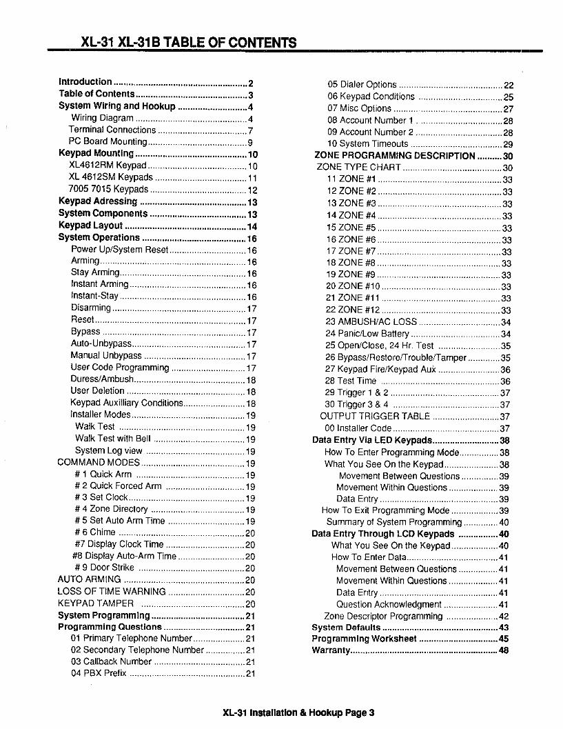
XL-31 XL-31B TABLE OF CONTENTS --
Introduction ... ..................................................2Table of Contents .............................................3System Wiring and Hookup ............................4
Wiring Diagram .............................................4Terminal Connections ....,,,,.........,,.,..,.,.,,..,..,,7PC Board Mounting..., ....................................9
Keypad Mounting .............................................loXL4612RM Keypad ........................................l OXL4612SM Keypads .....................................1170057015 Keypads, ..........12..........................l2
Keypad Adressing ...........................................I3System Components ....................................... 13Keypad Layout .................................................l4System Operations ..........................................16
Power Up/System Reset, ..............................l6Arming ...........................................................l6Stay Arming...................................................l6Instant Arming ...............................................l6lnstant-S!ay ...................................................l6Wsarming ......................................................l7Reset .............................................................l7Bypass ..........................................................l7Auto. Unbypass..............................................l7Manual Unbypass .........................................17User Code Programming ..............................17Duress/Ambush .............................................l8User Deletion .,..............................................l6Keypad Auxiliary Conditions .........................l8installer Modes ..............................................l9Walk Test ...................................................l9Walk Test with Bell .....................................19System Log view ........................................19
COMMAND MODES ..........................................l9#1 Quick Arm ,...........................................lg#2 Quick Forced Arm ,,,,,,,,.,,,.,...,.,.,,,,,,.,.lglg#3 Set Clock ...............................................l9#4 Zone Directory ......................................19#5 Set Auto Arm Time ...............................19#6 Chime ...................................................2O#7 Display Clock Time ................................20
#8 Display Au!o-Arm fime ...........................2O#9 Door Strike ...........................................20
AUTO ARMING .................................................2OLOSS OF TIME WARNING ,..............................20KEYPAD TAMPER ..........................................20System Programming ......................................21Programming Questions .................................21
01 Primary Telephone Number .........21..........2l02 Secondary Telephone Number,, ..............2l03 Callback Number .....................................2104 PBX Prefix ...............................................2l
05 Dialer Options ..........................................2206 Keypad Conditions ,.................................2507Misc Options ............................................2708 Acmunt Number 1 ..................................2809 Account Number 2,..,, ..............................2810 System Tmeouts .....................................29
ZONE PROGRAMMING DESCRIPTION ..........30ZONE WPE CHART ........................................3O
11 ZONE#l ..................................................3312ZONE#2 ..................................................3313zoNE#3 .................................................3314 ZONE #4 ..................................................3315zoNE#5 ..................................................3316ZONE#6 ..................................................3317zoNE#7 ..............................................3318ZONE#8 ..................................................3319ZONEW ..................................................3320ZONE#l O................................................3321 ZONE#ll ................................................3322 ZONE #12 ................................................3323 AMBUSH/AC LOSS .................................3424 Panic/Low Batfery ....................................34250pen/Close, 24 Hr. Test .........................3526 Bypass/Restorefirouble/Tamper .............3527 Keypad Fire/Keypad Auk .........................3628 Test Time ................................................3629 Triggerl & 2 ..,...,.,...................................3730 Trigger 3&4 ...........................................37
OUTPUT TRIGGER TABLE ...........................37OOlnstaller Code ...........................................37
Data Entry Via LEO Keypads ...........................36How To Enter Programming Mode................38What You See On the Keypad, .....................38
Movement Between Questions ...............39Movement Wthin Questions ....................39Data Ent~ ................................................39
How To Exit Programming Mode ...................39Summary of System Programming ..............40
Data Entry Through LCOKeypads ................40What You See On the Keypad ...................4OHOWTOEnter Data.....................41..............4lMovement Between Questions ................41Movement WtMn Questions ....................4lData Ent~ ................................................4lQuestion Acknowledgment ......................41
Zone Descriptor Programming .....................42System Defaults ...............................................43Programming Worksheet ................................45Warranty ............................................................48
XL-31 Installation & Hmkup Page 3
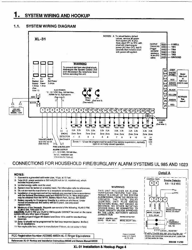
1, SYSTEM WIRING AND HOOKUP
1.1. SYSTEM WIRING DIAGRAM
~RE & BURGLARYi JAURMO~U(11 .i2.2VX,750W M.,
CONNECTIONS FOR HOUSEHOLD FIRE/BURGLARY ALARM SYSTEMS UL 985 AND 1023
WARNING
11- Nmqb-hb I&e, mbm b man” fammr if blown, do not solder i“ field.
FCCRqistm!ionNutier AE398E-69554AL-ERiqsr @uivafence,,0,”,,,0”,,.,
!,”6,, “.s P.,..,
,4.7,,,85,
Reference% xL-3i Hookup and l.s!allatlon l.stwctions N9340 and tin- ManualN9339 1-.
~_——— —— ____
“-0’ ‘A”” ~ I156Im 9,5- 12.2 Voc
—— __
N9338 11/93
XL-31 ln3allatiOn & Hookup Page 4

GRADE A CENTRAL STATION BURGLARY APPLICATIONS XL-3BUsingfheAdemco7622CDtimsmifte,wjti he XL.3Bwill ~rmit Grab A Ce”kal StatiO” %wiu,
——
1-Refer b Ademm7620ADV2and7920SEinstigationinstmctionforadditiondinformationandwmoleteWmsmitier
2-Programihe~L-3B m~gerquestions foc tigger 1-bu~la~,,tigger 2- phonehilu~, mgger 3- AC Ims,ati mgger 4- low bttmy,
3-Pmgmm &mnels used on7621AD fw invetid inputwith no delay.
4-me XL4612TC Mgger~b is needd toIntemnneti the 7621AOWnsmitter intetiaa withtie XL+S,
5&e tie spcialinstictions on ~ge 9 oftie 7620ADV2 manual.
6%ebrto Fim Bu IW%[nstmmenb XL-3 ,No.
N9116 ~nskllahonlnsticbons br rnmpletep~rmmin andhook-up
!dawon tie L-3B,7-The 7621AD ~smi~r
intetiarn shall b install%within tie mnwol panelenclosure,
[
21,
(+)
,9 (-)
ADEMCO TRANSMITTER INTERFACE(mm N,.w)
NQ. 7621AD
Jllll659ENADEMCOTELOQ,K0“. P“&“, m,s,om F
}=
11111
LINE FAULT MONITORXL4612TC
-w
NE@TIVE(BLACK)
CABLE TRIGGER1 (BROWN)TR19GER 2 (GREEN)
CONNECT TRIGGER 3 (ORANGE)TO XL4B “TRIGGER3 YELLWTRIGGEROUTPUT
POSITIVE RED NOT USEDPROTECT FROM SHORT
——
XL-31 lnmaila3@n & Hmkup Wge 5
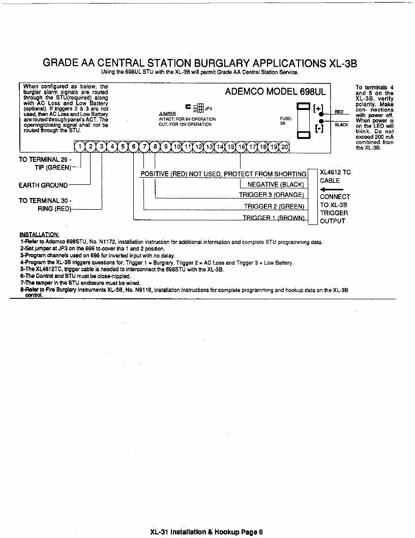
GRADE AA CENTRAL STATION BURGLARY APPLICATIONS XL-3BUsing the 66BUL STU with the XL-3B will pmit Gra& AA Cential S&tion %wirn.
= ~~ JP3~lNTAct FORev OpERATIONcuT:60R12vOpEMATION
ADEMCO MODEL 698UL
D[+1FUSE3A
[-Tu
2 13 14 15 16 17 1S 19 20
I-- —-. . . . -. I I 1 IIU ltHMlNALZ9- I I I Ill I
d““‘“J1TIP (GREEN)J II I
POSITIVE(RED)NOT USED,PROTECTFROMSHORTING— XL4612TC
~RTH GROUND NEGATIVE(BLACK)CABLE~
TO TERMINAL30-TRIGGER3 (ORANGE) CONNECT
RING(RED) TRIGGER2 (GREEN) TO XL-3B
TRIGGER
To terminak 4and 5 on theXL-3B, verifypoladty, Makecon- nectionswith pwer off.men Pwer ison the LED willblink, Do notex~d 2W mAcombned komthe XL-3B.
l-~~r to Ademco 696STU, No. N1172, insulation instruction for atiitional information and complete STU programming &M.2&t jum~r at JP3 on the 696 to cover the 1 md 2 psition,3.Pmgram timnels u=d on 6~ for inveti input with no delay,4.P~mm the XL.3B tri~gem questions fo~ Tfigger 1- BurglaV, Trigger 2 = AC Loss and Ttigger 3 = Low BaneV,5~e XL4612TC, tigger c~le is neWW to inMrconne@ tie 69~TU with the XL+S,&The Cont~ md STU must be closmnippled,7-The tipr in the STU enclosure must be wir~,8-&&h~ fin SuWlaV InsWmen& XL.3B, No. N9116, Instdla!ion Instructions for complete programming and hookup data on me XL-3B
XL.31 Instsllstion & Hookup Psge 6

3(+) & 4(.)
5(+) & 4(-)
5(+) 6(s)
7&8&)8(.) & 9lo&ll(.)11(.)&1213& 14&)14&) &1516& 17~)17P) &1619& 20(-)20~) & 2122& 23~)23~) & 24
1.2. TERMINAL CONNECTIONSTERMINALS DESCRIPTIONl&2 TRANSFORMER:
Connect an the 16.5 VAC 40VA transformer, ufihzing 16awg wire at a data~enot to exceed 15 feet from the panel, to an unstitched 120 VAC outlet.
Do not use any other transformer since this may resuff in improper operation (>rdamage to the unt.
The AC/LOW BAT LED on the keypad will remain ON while AC ~wf~r ispresent. If an AC loss omurs the AC/LOW BAT LED will turn off immediately.If AC remains OFF for 15 minutes, the system will pulse the ke~ad buzzer ardtransmit to the central station, if programmed. THE KEYPAD BUZZER CAFIBESILENCED by entry of any valid user code. When AC restores the AC/LOWBAT LED will fight and a restore code will be reported, if programmed,SIREN/BELL OUTPUT:
The control panel mntains a buih in siren driverwMch is selected within questionnumber 070fthe programming sequence, Iftheairen driver isselected!henthe programmed sounds will be generated for fire and burglary condifionla. Ifprogrammed as a bell outpdt then the total output power available for soundingdevicesiel amp(750mA for ULinstallations) atll-12.2V. lnULhouselbMinstallations, youmust usean FBlmode1671 speaker anditmust bemoulltedindoors. These terminals will deliver CONSTANT output on BURGLARV,AUDIBLE PANIC and BELL TEST. On a FIRE condition, a PULSED outpultwillbe generated. There are separate bell cutoff times programmable for Burgilal~and Fire conditions within the programming sequence.REGULATED POWER (12.2.12 .7VDC):
The total regulated output power for motion detectors and other external devicf~sis500mA (200mAfor UL installations at 13.8VDC, with lessthan100m1tPPripple.
The total regulated output capacity of the control system includes the ~)wl~ravailable from these terminals as well as the power used by the keypads andsmoke detectors. Therefore, to determine the total pwer available from ttleseterminals subtract the pcwer consumed by the keypads and smoke detedors.SMOKE DETECTOR POWER: (9.%12.2V)
This system will accept 12VDC four(4) wire smoke detectors only.Approximately 50mA of current is available at these terminals for powering alldetectors and an E.O.L. relay FBI model 620. For UL installations see wirirlgdiagram for hookup. Due to the different power requirements of smol(edetectors, the system may only support one smoke detector.
These terminale adhere to the fire verification and reset logic which is explainf)din the Zone types section of this manual. Manual reset of smke detector W]wercan be accomplished by entry of any valid user code after clearing alarmmemory,Zone 1 (Optional 2.2K EOL resistor) [Default = DELAYZone 2 (Optional 2.2K EOL resistor) [Default = INTERIOI?]Zone 3 (Optional 2.2K EOL resistor) [Default = PERIMETE13]Zone 4 (Optional 2.2K EOL resistor) [Default = PERIME1”E17]Zone 5 (Optional 2.2K EOL resistor) [Default = PERIME1E13]Zone 8 (Optional 2.2K EOL resistor) [Default = PERIMETER]Zone 7 (Optional 2,2K EOL resistor) [Default = PERIME1”ER]Zone 6 (Optional 2.2K EOL resistor) [Default = PERIME1E13]Zone 9 (Optional 2.2K EOL resistor) [Default = PERIME1E13]Zone 10 (Optional 2,2K EOL resistor) [Default = PERIMETER]Zone 11 (Optional 2.2K EOL resistor) [Default = PERIME1-EIR]Zone 12 (Optional 2.2K EOL resistor) [Default = PERIME1-EIR]
NOTE: Connecting JP1 on the circuit board and enabting the option in Questi(>n6 location 4 configures Zone 12 as a fast loop res~nse zone (8 -10msec.res~nse). When selected, trigger number 3 cannot be used. Also tlhefast response zone must bean alarm on open type of device. If trigger number3 is used then cut JP1 and disable fast loop response in question 6 locati~~n4.
XL-31 Irsatallation & Hookup Pege 7

GROUNDING LUG
25262728
2S393132
TRIGGER OUTPUTS
SACKUP BATTERY
ZONE INFORMATION
Normally closed devices may be wi~ed in series, an~or normally open devicesin parallel with the 2,2k ohm end of tine resistor on all zones (EOL supewisionoptional per zone). The maximum loop resistance may not exceed 100 ohms.The loop response time is 280 ms on all zones, except for zone 12 which canbe programmed for fast resWnse (8 -10 msec). The factory defautf values foreach zone is tisted in the table abve, however any zone can be programmedfor the following types: Delay, Perimeter, Interior, Fire, Keyswitch, 24 Hr. Alarm,or24Hr. Trouble. Furfher explanation of thezone types can be found in theSystem Programming section of ttis manual,EARTH GROUND:
Connect this grounding lug to a cold water pipe utitizing#16AWG wire at adistance of no greater than 15 ft. If the premises pipes terminate in PVC, this~~~~AID~t be connected to a six(6) foot grounding rod.
A maximum of 4 keypads may be wired to these terminals. The connectionsare as follows; 25 (RED = positive power), 26 (GREEN = data out), 27(YELLOW = data in), 28 (BLACK = negative), EachXL4612RM andXL4612SMkeypad draws approximately 30ti, others draw approx. 60mA. Maximumkeypad length is 500 feet using 22 gauge wire. NOTE: XL4612RM andXL4612SM cannot appear onthesame system withthe 7OO5L,7OO5or7Ol5keypads. NOTE: Keypads must be connected to system prior to ~werup. If thekeypad contains a dip switch for addressing then the address must be aet tothe appropriate address prior to ~werup. A system powerup must be performedwhen adding new keypads to the system,TELEPHONE LINE:
Connect the FBlmode1388 cordasfollows; 29( GREEN =Telco Tip),30(RED= Telco Ring), 31(BROWN= Home Tip), 32(GRAY= Home Ring). Inseti themodular plug into an approved USOCRJ31 Xjack (era CA31A jack for Canadaninstallations),
The FCC registration number is (AE398E-69554 AL-E), and the ringerequivalence is (0.OB). This security system should not be connected to partyHnes,or coin operated phones,
Futihermore, this device should not be connected to a phone line which hascall waiting, unless the call waiting interrupt numbers are programmed into thepanel dialing sequence.
The control panel contains four programmable outputs. These utilization ofthese outputs are selectable within the programming sequence (questions 29& 30). In order to connect devices to the triggers use connector XL4612TC(trigger cable). Trigger outputs are switched negative.
The trigger output labeled VBELL is a regulated power eupply, This output isprotected by the BELL fuse and should only be used with devices requiringconstant regulated voltage (12VDC), For ULinstallafions, the trigger outputsshall be connected to devicee rated to operate over the range from 10.1 -14.OVDC at 50 MA, The connected devices shall be mounted within 20 feet ofthe system orwith the mnnection completed with a dedicated, grounding circuit.
The RED(+) and BLACK(-) flying leads must be connected to a 12 VDC 4-6AHGEL CELL, to serve as backup power in the event of AC loss.
The system performs abaftery test approximately every 4.5 minutes. Lowbattery condition occurs at nominal IIVDC during this test. The ke~adAC/LOW BAT LED and buzzer will PULSE SLOWLY when low battery conditionis detected, The system will report this con~fion to the CS if programmed.Battery restoral will owur WITHIN 4.5 minutes, at the NEXT battery test. THEBUZER MAYBE SILENCED by entry of any valid user code,
Ground etart capabi~ty can be added to the system through the output triggersof the control panel. If ground start is desired then this must be programmed aatrigger number 1. Ground sfati muet not be used in a UL installation.
XL-31 Installation & Hookup Page 8

1.3. PC Bwrd Mounting
untlng the XL-31 PC Wrd
~fore mounting the circuit hard, be certain that the appropriate metal knockouts have Men remved. DO NOTATTEMPT TO REMOVE THE KNMKOUTS A~ER THE CIRCUIT BOARD HAS BEEN INSTALLED.
1. Hang the three mounting clips on the raised cabinet tabs. Obsewe proper tip orientation to avoid damage to the clipwhen mounting screws are tightened and to avoid problems wth Inaetiion and removal of the PC board.
2. Place the plastic spacer provided into the hole between terminals 27 and 28 from the back of the board. This will pn~vktea~tional auppcrf for the PC board.
3. Insert the top of the circuti board into the alota at the top of the cabinet. Make sure that the hard rests in the sk~lsaaiticated In the diagram shown below.
4. Swing the base of the board into the mounting ctips. Place the grounding lug provided on top of the PC board nearterminal 23 of the control panel and secure the ground lug to the PC bard. Secure the board info the cabinet with theaccompanying wrews.
DETAIL SIDE VIEW OF
CLIP INSTALMTIONA-CABINET TAB
WITHOUT CLIP8-CABINET TAB
WITH HANGINGCLIP
OETAIL SIDE VIEW
OF CLIP AND BOARDINSTALLED
XL31 Irsatallatbn & Hmkup Page 9

2. KEYPAD MOU~lNG
2.1. XL4612RM METAL KEYPAD
FLUSH MOUNTING USING DOUBLE GANG BOX
1- Create an opening and mount a standarddouble gang ~x.
~~~
_.__ —- 2- Semre keypad to double gang hx as shown in
(7
- -%””-”77——.. diagram below. Note: The double gang box should
& : :[:][::1[;0be mounted flush with the wall in order for the
%. keypad screws to ft.0“ ~[:JuL]. o[:][:juTJ NOTE: For UL installations, munt the XL4612RM
f-- . . . . .~ ~ ~~~[~[:1 to an earth grounded outlet box.. . .
. L700 1—---e.–-=:=-
FLUSH MOUNTING WITH MOUNTING RING (Using the XL4600TR)
MOUNTING KEYPAD IN CONTROL PANEL ENCLOSURE
1- Create the desired opening where keypad is tobe mounted, using the inside of the munting ringas a template. NOTE: This opening should bemade between studs.
2- Secure mounting plate towall through thefourouter holes using suitable mounting hardware (notprovided).
3- Connect keypad wiring to control panel andsecure the keypad to the mounting ri~ using thefour painted screws provided.
1. Depending on type of installation run thekeypad widng out of the rear, top bottom or sidesof the backbox.
2- Attach backbx to wall at desired height
3- Insert XL4612RM keypad into backbox andsecure with the four screws provided.
1- Remve keypad knockout from front of metalbox enclosure as shown.
2- Inseti XL4612RM into opening from front ofenclosure.
3- Secure keypad to enclosure using thepainted metal screws and nuts provided.
XL-31 Inatallatlon & Hookup Page 10

2,2. XL4612SM KEYPADThe XL4612SM Keypad may be surface munted in the following ways
A. Directly to a control panel having a keypad wtout on the front of KSenclosure.
B. Directly to a single or double gang electrical junction bcx.
C. Oirectly to a wall or other surface.
COVER
‘E’’’’’[!g:;;l;l70 REm”E COVER. ,NSERT SMALL
SCREWDRIVER EWE MO W,ST.
Diagram 2: BOTTOM VIEW OF KEYPAD
1. Remove the keypad wver assembly from theresr mounting plate. Insert a small screwdriverblade in the COVER PRY-OFF SLOTS at thelower edge of the keypad (see Diagram 2 ) andtwist to pry off the cover assembly.
2. Mount the rear plate (see Diagram 3).
Note: The plate is correctly oriented when tis Ioartnumber, molded into the plastic, is upright.
A. MOUNTING DIRECTLY TO CONTROLPANEL ENCLOSURE
Ifthe control panel hasakeypad mtout on thefront face of its enclosure, remove the cutout andmount the plate to the enclosure’s face via HOLES“A ( see diagram 3) and the four screws and riutsprovided.
Note: Certain affack~roof enclosures are nc~tprovided with a keypad cutout.
B. MOUNTING DIRECTLY TO AN ELECTRICALJUNCTION BOX:
The plate can be mounted directly to a singl(>cIrdouble gang electrical junction box. Use thescrewholes provided and HOLES “B for a singlegang box or HOLES “A for a double gang hx.
C. MOUNTING DIRECTLY TO A WALL OIROTHER SURFACE
Provide a wiring hole in the mounting sutiilct~.Postion the plate’s WIRING OPENING over thehole and mounting plate, using HOLES “A” arr~~c~r“B in conjunction with appropriate mountinghardware (not provided) for the type of surface.
3. Complete the keypad wiring as required for thecontrol with which the keypad is to be used.
4. Replace the keypad cover assembly on the reflrplate. Sfatiing at the upper. edge of the plat[>,engage the plate’s WO HOLDING HOOKS (seediagram 3) into the recesses provided for tl]arninside the upper edge of the cover assembly andsnap the lower edge of the cover assembly andsnap the lower edge of the rover onto the twoSNAP HOOKS at the lower edge of the plate.
Note: (Optional) If desired, cover and plate can befutiher secured together by inserting a screw(provided) into the SLOT at the keypads Iowt?redge.
XL-31 Inefalletbn & Hwkup Page 11

2.3. MOUNTING 7005 and 7015 KEYPADSKeypad mounting is identical for both the 7015 LED and 7005 LCD versions, Keypads can be surface mounted or flush
mounted as described below, NOTE: After mounting the 7005 LCD Keypad at eye level, you can adjust the dieplay inteneitylevel to suit the user by a@usting the intensity control located behind the keypad door,
SURFACE MOUNTING
1. Select a mounting location and place the rear
~___ plate of the keypad on the wall. Mark the location
6
r“ i —
of the cutout for the keypad wiring cable,
‘“k y,:_@~2- Create a keypad opening. Connect the keypad
[
8.% n 8%! wiring to the control panel w/ 4-wire connector./, !,,,,&. s. ~ –
/ ~ :g ‘“
3- Place the keypad wiring through the cutout and
!Isecure fhe backplate to the wall (see diagram).
L-~4- Connect the keypad wiring connector to thekeypad and place the keypad on the munting
~’ ~1 ,Ji ~.
L
plate attached to the wall,
5- Secure the keypad to the rear mounting plateby affacting the 5/8 inch screw provided in thelower hole, located behind the keypad door.
RECESSED MOUNTING
~ 13,,,a,, >●
E
4“
—
1- Select a mounting location. For recessedmounting this must ba between two studs.The rearmounting plate is not used for recessedinstallations.
2- Create an opening in the wall exactly 4 incheehigh by 5 13/16 inchee wide,
3- Turn over the keypad and remove the Phillipshead screw (item 1 on diagram) in the upper lefthand side of the keypad printed circuit board.Note: This screw is located immediately to the leftof the keypad wnnector.
4- Attach the black metal mounting Strap to therear of the keypad as follows (see diagram);
- Face the pointed end of the mounting strap facingthe keypad front. This will be used to latch ontothe inside of the wall.
- Place the small white plastic spacer underneaththe mounting strap. Secure the mounting strapusing the 5/8 inch Phillips head screw (supplied)and the plastic spacer to location 1,
- Secure the other end of the strap (location 2 ondiagram) to the white plastic opening using the
A APhillips head screw removed in step 2,
5- Connect the white plastic tab into the roundopening immediately behind the keypad door.
QG Place the longer Philhps head screw (included)through the opening inside the kaypad door and
qR begin to tighten the screw. Tighten the screw and\ leave the tab in a down position,
8- Run the keypad wiring to tha control panel and
~) ‘\l $ 9abetheinsideofthewal
attach the wiring to the keypad.
7- Place the keypad into the wall opening with theside containing the black matal strap first until i
8- After inserting the side of the keypad with themetal strap, insert the other side into the openinguntil the enfira keypad is firmly in the wall.
9- Tighten the screw inserted in step 5.
XL-31 Installation & Hookuo Paoa 12

3. KEYPAD ADDRESSING
The 7005, 7005L and 7015 keypads contain dp switches to set the addresa of the keypad. This fdefst~iesthe kemad tothe system. NOTE: There is no switoh on the XL4612RM or XL4SI 2SM keypads.
This switch ccntains 4 locations and is numbered SWI - SW4 and is tited ae folbws:
7005, 7005L, 7015 Keypads Inetie of open door on left hand eide of keypad
Each keypad must be assigned a un@ue keypad address fmm the table below. For example, if there are 4 keypads (2LCD and 2 LED) then the LCD keypads can be numbered 1 &2, and the LED keypads shcutd be numbered 1 & 2.
W~PAD -~
1 ON OFF OFF
2 OFF ON OFF
3 ON ON OFF
4 OFF OFF ON
5 ON ON OFF
6 OFF ON OFF
7 ON OFF OFF
8 OFF OFF OFF
NOTE: SW4 is not used on these keypads.
IMPORTANT: Keypad addresses must be set for the 700, 7005L5 and 7015 keypads prtor to system ~wemp for all ofthe keypads connected to the system. If addtional keypads are added to the system, the keypads must be set to the desiredaddressea (in accordance with table above). Neti a pwer up mst be perfcrmed on the control panel in order for the iletwkeypads to be recognized.
4. SYSTEM COMPONENTS AND ACCESSORIES -.
The following configurations and aaessories are available for the XL-31 and XL-31B systems:
CONTROL PANELS
XL-31 A 12-zone contro~ccmmunicator for UL Residential Burglary /Fire applications. Keypada available
XL-31 Bse aratelyA !2-zone mntrol/communicator for UL Commercial Wr hry applications. The control is housed in a lIL
!Listed attack-proof enclosure. Keypad available separate y.
SYSTEMS KEYPADS
XL4612RM Surface mount metal plate LED based keypad for XL3/XL3B syefema. Includes XL4600TR trim ring forflush mount installation.
XL4612SM Surface Mount LED keypad for the XL3 and XL3B aystema.7D05L LCD based ke~ad, containing large character LCD display, surface or recessed mount wtih two fine LC[)
dia lay.7005 LCB based keypad, sutiace or recessed mount wfih two UneLCD dieplay.7015 LED based keypad, sufiace or recessed mount.
Note; The XL4612RM and theXL4612SM cannot be used on the same systam with the 7005f1015keypads.
ACCESSORY PRODUCTS
*XL4612TC Trigger cable connector for XL-31 systems.*XL4600RMBX Back box to surface mount theXL4612RM metal keypad.
‘Not tested for UL apphcatiins
XL-31 Inetallsflon & Hcokup Page 13

5. KEYPAD UYOUT
=8
XL4612RM KEYPAD
2
\
3——
/4
/1
XL4612SM KEYPAD
1) ZONE STATUS LEDSThese LEDS display the aurrent zone status including slarms, bypasses, troubles and fauns. Each oandtion will aause
~hese LEDS to operate dtierentiy as follows:
ALARMS Fast Blink (approx, 150 ms. ON -150 ms. OFF).
TROUBLESSbw Pulse (epprax, 600 ms. ON -S00 ms. OF~.
BYPASSES Wink (100 ms. ON -900 ms. OFF). Zone bypasses are displayed as a very slow wink of thezone LED light.
FAULTED Z NES Sol ON. F UIe z nes are tha bwest ~ Itihtion. Fauked burgla~ zonesare dieplay$wkh the L%Dsolld?y&flw%ile the system la dignn~
NORMAL OFF
2) ARWDISARM LEDThis LED indbates whether the system Is mrrently armed (ON) or diaermd (OFF).
Fast Blink = Alarm Mode
Slow Wink = Fail to Communicate with Central Station
3) ACILOW BATTERY LEDThis lndbator light displays the current power status of the panel as follows
ON = AC is prssent, Battery aondtiion normal
OFF m No AC, runnl~ on battery ba~up
Slow Blink = Low batte~ oandklon deteoted
Fast Blink = Telephone Line failure
XL.31 Inatallatfan & Haakun Paaa 14
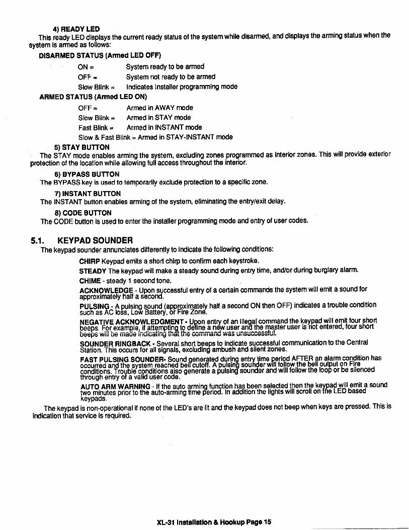
4) READY LEDThis ready LED displays the current ready ststus of the system while disarmed, and displays the arming status when the
sy~em is armed as follows
DISARMED STATUS (Armed LED OFF)
ON= System ready to be armed
OFF = System not ready to be armed
Slow Btink = Indicates Installer programming mode
ARMED STATUS (Armed LED ON)
OFF = Armed in AWAY mde
Slow Blink = Armed in STAY mode
Fast Bhnk = Armed in INSTANT mode
Slow & Fast Bink = Armed in STAY-INSTANT mode
5) STAY BUTTONThe STAY mode enables arming the system, excluding zones programmed as inferior zones. This will provide exfelric}r
protection of the location while allowing full access throughout the interior.
6) BYPASS BUTTONThe BYPASS key is used to temWrarily exclude protection to a specific zone.
7) INSTANT BLf~ONThe INSTANT button enables arming of the system, eliminating the entry/exit delay.
8) CODE BU~ONThe CODE button is used to enter the installer programming mode and entry of user males.
5.1. KEYPAD SOUNDERThe keypad sounder annunciates differently to indicate the folbwing cctitions:
CHIRP Keypad emfis a shofi chirp to mnfirm each keystroke.
STEADY The keypad will make a steady sound during entry time, an~or dudng burgla~ alarm.
CHIME - steady 1 second tone.
ACKNOWLEDGE - UWn successful entry of a csnain commands the system will emfi a sound forapproximately half a second.
PULSING - A pulsing sound (approximately hati a second ON then OFF) indicates a trouble condtionsuch as AC Icss, Low Battery, or Fire Zone.
NEGATIVE ACKNOWLEDGMENT - u. n entry of an ille al com~nd the keYPadwiIl emfi four s~~TY 3beeps. For example, If attemptm tc de me a new user an the master user is net entered, four shcti
be5DSwill be made mdicatina tha the command was unsuccessful.
SOUNDER RINGBACK. Several shcrf beeps to indicate suwessful @mmunication to the CentralStation. This owre for all signals, excluding ambush and silent zones.
FAST PULSING SOUNDER. Sound enerated during entry time period AF7ER an alarm m~iion ha$foccurred and the system. reached bel cutoff. A Pulsin9 sounder WIIIfo!low the bell outPut on F!re
conditions. Trcuble conditions also generate a pulsing eounder and WIIIfellow the lcoP or be sllen~dthrough entry of a valid user code.
AUTO ARM WARNING - If the a@o arming function has .Men aeie~ed then the ke Pad will emit a ~u~lrtwo minutes prior to the auto-arming time period. In addtlon the Ights will scroll on he LED based
keypada.
The keypad is non-operational if none of the LED’s are ~t and the keypad does wt beep when keys are pressed. This isindication that service is required.
XL-31 Inatalletbn & H~kup Page 15

6. SYSTEM OPEWTIONS
6.1. POWER UP/SYSTEM RESETUWn inhlal system ~werupallofthe I@htson LED based keypadswill@onand the sounderwllloparateforepproximate~
10 WCOMS. This OWUrS Orr a total powe~p, system reset or after wmpletlon of system programming. If the total System~wer is lost then upon power reetoral, the system will return to the prevbus arming state.
6.2. ARMING THE SYSTEMFAIL-SAFE ARMING:
me system can be armed on~ if all burglary zones are good (not fauked) and the R~DY LED is on.
ARMING:Enter any programmed four digit user code.
NOTE: The factory defau~ user number 1 arming code is 1234.
The ARMED LED will fight and the ueer may exk through an exiVentry zone for the time parfod programmed as the ex~delay. The LCD keypad displays “EXIT NOW on the semnd hnefor the duration of the exit delay.The system can be armedwhhout the bsckup battery being wnnected, however the AC/LB Hghtwill flash.
6.3. STAY ARMINGDepress the STAY BUTTON followed by a four digti user wale, This will arm the system wkh all programmed Intetir
zones excluded.
KFYPAD RFSPO~
XL4612RM, XL4612SM ARM = ON RDY = Slow Blink
7015 ARM = ON STAY = ON.
7005
m6.4. INSTANT ARMING
Depress the INSTANT button and a four dlgh user code,
The INSTANT mode will am the system wkh all programmed exWentry zones as Instant.
KFYPAD RFSP_
XL4612RM ARM - ON RDY = Fast Blink
7015 ARM = ON INSTANT = ON
7005
mNOTE: The INSTANT mode can be disabled through programming questfon 06,
6.5. INSTANT+TAY ARMINGDepress the INSTANT then STAV buttons and a four digit user wds.
The INSTANT STAY mde will arm the system wkh the characteflstics of Mth the INSTANT and STAV males. Thesystem will be armed wkh the Interior zones bypassed and the delay zones instant.
KFVPAD RF~
XL4612RM ARM = ON RDY = FaS & Slow Blink
7015 ARM = ON INSTANT = ON STAY = ON.
7005
-
XL-31 Inatallatbn & Hookup Page 16

6.6. DISARMINGDepress any vahd four(4) digit user rode. The ARMED LED will extinguish.
If an alarm condition exists or had occurred while the system was armed, the respective zone(s) LED(s) will blink rap~ly.On the XL4612RM and XL4612SM keypads the ARMED LED will bhnk rapidfy, on the other keypads the READY LED willbe blinking rapidly. This condition is clasa~ed as ALARM MEMORY and can be cleared through entry of a valti user rode.
6.7. RESETReset is accomplished through the entry of any vahd user rode. This can be used to reset the smoke detectors affadled
to the system, silence any bells, or clear the keypad display or sounder.
In addition an option exists, for making the ● key to act as a reset for clearing the sounder, and alarm memory. Thisprogrammable option can be obtained through lo~tion 1 of question 06.
6.8. BYPASSBypassing is performed to temporarily exclude zones which are fauky or not ready from activating the system.
Depress the BYPASS button followed by any vahd four(4) digit user code, followed the zone number (01 - 12).
EXAMPLE: BYPASS ZONE 6 (Assume user code of 1234)
BYPASS 123406
Subsequent bypasses can be made by depressing the BYPASS button followed by another zone number within a telnsecond period. After this ten second period k will be necessary to enter the entire command inc~ding the user code.
NOTE: An option exists for Quick Bypassing which does not require entry of a valid user code. If this option ie selected(see question 06 location 3) then BYPASS followed by the two digit zone number (01 - 12) will bypass any bypassable zone.
In addtion, an option exists to restrict user b~asses to a maximum of three zones. This option can be selected thrOIJglhprogramming question 07 location 3.
After a successful bypass the keypad sounder will emit the acknowledge beep, and the respective zone LED will WINt(SLOWLY.
In addfion the following rules for bypass exist;
. FIRE zones cannot be bypassed
. 24 hour zones can be bypassed, however they CANNOT be unbypassed if they are violated.
. Zones can only be bypassed while the system is disarmed, at which time visual indication will be ~sPlaY~.
. Bypass signals will be transmitted to the Central Station UPON ARMING f a bypass code has beenprogrammed.
NOTE: Zones w~ch are bypassed are not protected when the system is armed.
Programmable options exist to determine whether bypassed zonee are automatically unbypaeeed after disan a~whether bypassee “aredisplayed on the keypad when the system is armed. Both of theee options can be programmed wtiWInbcafion 3 of question 07.
6.9. AUTO UNBYPASSAII burglary zones wtich are bypassed can be automatically unbmassed upon sYetemdsarm. 24 hour zones w~ch have
been bypassed will be unbypaseed only if they are normal. The autounbypaesfeature is a programmable option (eeeque#tioln07 of the programming sequence).
6.10. MANUAL UNBYPASSUNBYPASS removee an existing bypass from a currently bypaased zone. The procedure is the same as bypass.
6.11. USER CODE PROGRAMMINGUsers codes can be entered or modified directly through the keypad.
The system ~~~~Nuw ueer wales (4 digks each) with the following apphcstions;
01 &02 Mster User [Bfault = 1234User#1] (Sw note 1)03-27 UserNumber03-27 [Wfeult = null]26 UserNumkr 28 Mr stie (Sw note2)29 Uwr Number29 @fauft = nu~] W only cde, seenote 330 hbush Code mfauft = nuff] Sw no~ 4
XL-31 Installation & Hakup Page 17

NOTES: 1. Only the master users (user number 1 &2) can program or modtiy other users.
2. User number 28 will be the system “door stfike” code Hany of the triggers is defined as a door strike trigger. ff thetrfgger is defined then entry of this user code will activate that trigger for a period of 5 seconds. If a door strike (or awess)trigger is not defined then this user code can be utihzed as another user code. In addition thera is an option to allow afl usercodes to act as a door strike code. If this option is selected (question 06, location 3) then all users can activate the door strikethrough the W command. (See command modes)
3. User number 29 is a system wide arm (maid ) wde if the ARM only code is selected for question 08 Iocatbn 3.
4. User number 30 will be the systemwide ambush code Mthere is an ambush CS transmission code programmed intoquestion number 23, If no code is defined then this user number 30 will be a~ther available user code.
USER DEFINITION PROCEDURE: CODE [USER] [USER number] [USER ID]
CODE Code button on keypad
[USER] Master User ID code (user #1 or M)
[USER number] Desired user to be programmed (01-30)
[USERID] Four digti user code. Vahd digfis are O-9
Example: Define user number 03 wtih an ID of 7493. (Assume master user wde is 1234).
CODE 1234037493
An acknowledge sound (steady tone) verities a successful user code programming.
A negative acknowledge sound (4 short tones) indicates unsuccessful programming.
If additional user programming is necessary, repeat the procedure fisted above.
User programming can be performed while the ayatem la DISARMED ONLY.
If a dialing format is programmed which transmits openin@cIosing by user ID, each user will re~rt the respectfie usernumber. User numbers greater than 16 can only be reported as the actual user number it the FBI Superfast or ADEMCOpint ID formats are used, Pulse formats can transmit different opeticlose and cancel codes for users 16-30 as defined inquestion 25.
DURESS/AMBUSH
If ambush capabi~iy is required then an ambush transmission code must be entered wittin the programming sequence.When ambush has been enabled (see programming question 23) then the user number30 code will be used as an AMBUSHhale. In ttis mode, entry of the user number 30 code will ARM or DISARM the ayatem and transmit the ambush mde to thaCentral StatIon. Fudhermore Kopening/closing by user reWrting Is programmed, user number 30 wIII be re~rted along whhthe ambush code.
If ambush has not been programmed then user number 30 can be used as an ordinary user code.
ARM ONLY CODE [USER 29 CODE]
Defining number 29 ss an ARM only code means that the code can only arm the eystem and WOUHbe ueed for a ueersuch as a maid or temporary user of the system. This Is obtained through location 3 of question 08.
6.12. USER DELETIONRemoval of users from the system can be performed as follow%
USER DELETION PROCEDURE: CODE [USER] [User number] #
Where:
CODE is the CODE button on the keypad
[USER] Master ueer mde
[User number ] Re resents the user number bein deleted, (03-30). Note: User number 1 & 2 (master? %user codes) canno be deleted, however they can e modtied.
# is the # (Wund) key on the keypad.
6.13. KEYPAD AUXILIARY CONDITIONSThe system has the atitity to transmit four separate keypad auxitiary conditions as follows:
PANIC #’
FIRE 79
AUX. 13
AMBUSH [USER CODE number 30] If an ambush @de has been programmed.
XL-31 Installation & Hookup Page 18

Audible panic can be RESET BY ENTERING ANY VALID USER CODE.
The keypad FIRE and AUX mtitiona are selectable through the programming sequence.
The ambuah @de will be user number 30 if an ambush tie ia p~rammed in question number 23.
6.14. INSTALLER MODESThe panal containa tha following installer commands
SEQUENCE: CODE * [INSTALLER] [1-4]
Where:
CODE = Depression of the CODE key
● = Depression of tha * Key
[INSTALLER] = Entry of the four digit installer @de. Note The defauh installer code is 4612.
[1-4] Entry of 1-4 as follows:
1 = Installar Keypad Programming
2= Walk Test
3 = Walk Test wtih bell
4 = System log view
NOTE: Ether walk test mde diaablea the pane~s alarm funtions. The mndmlon is idenffied by ‘WALK TEST MOIDE”on the LCD keWads and flasting of the “RDW and “ARM” LEDs on the LED type keypads.
WALK TEST
The keypad will beep and annunciate with activation of aach zone while in this mode. Press the ● key to rastart and rdtumto the pfior panal status.
WALK TEST WITH BELL
Smilar to walk test except that the bell will be tested uWn entering the walk test mode.
SYSTEM LOG VIEW
Tha system retains history the past 6 events (alarms and troublas)
UWn entry to the system log view, LED based keypada will display alarms as faat bhnking ~ihfa and zona troubles swsbwbhnking ~ghfs. On LCD based keypada the~splay will show the events one at afime efarflng from otiesfeve~.Depreaaion of any key (except ● or bypass) will scroll bachards through the events. To exit from the system @ view fumticlnpreaa the * key. To clear the system log press the BYPASS key.
6.15. COMMAND MODESThe end user can parform the following commands
QUICK ARM [#1] If quick arming haa been enabled than enf~ of # 1 will am the system wklbtithe need for a user coda.
QUICK FORCED ARMING [#2] If quick forced aming has been enabled then entry of # 2 will arm the systemand bypass any bypassable zones that are not ready.
SET CLOCK [#3] To set the time of the system clock entec
# 3 [USER] HR MIN
where:
[USER] vahd user code
HR = Hour of day (24 hour time, example 3 PM = 15)
MIN = Minute (00 - 59)
The system time clock is used for the system test transmission as well as tlheauto-arming function. NOTE: Question 07 location 4 determines ti a user tieis required to set the system time; othe~ise enter # 3 HR MIN.
ZONE DIRECTORY (LCD Keypada) [# 4] To scroll through the zone descriptions on the LCD keypad enter # 4.
AUTO ARM TIME - [#5] To aet the time of day for auto-arming on a penanent basis enfec
# 5 [USER] HR MIN
where:
[USER] vatid user mde
HR = Hour of day (24 hour time, example 3 PM = 15)
XL*1 Installation& Hookup Page 19

MIN = Minute (00 - 59)
Thepemanentfime representethetime ofdaythattheaystemwill automaticallyarm ti the eystem is not already armed.
NOTE: Auto-arm time command can also be operated withoul entry of a user code based on the information programmedin question 07 location 3,
CHIME [#6] To turn the system chime on and off enter # 6. If chime had been ON, ttis willturn itoff. NOTE: Thec~mefeature can be selected by zone andthe#6functionwill toggle the chime feature for the entire system.
DISPLAY CLOCK TIME [#7] Display the current time by entering #7. A user code is required the user-erequired option is selected in question 07 digit 3.
DISPLAY AUTO-ARM TIME [#6] Display the current auto-arm time, preea #e. A user @de is required the usercode required option is selected in question 07 digit 3.
DOOR STRIKE [#9] The door strike trigger can be activated as followq
#9 [USER] ~rigger number]If all ueers have been authorized for door strike (see queetion 06 location 3) then any vahd user code can activate a door
strike trigger. lfthe''all users'` option hasnotbeen sele@ed then only user number 28isthe only usercdea@hoflzedtoactivate the door strike,
NOTES: (l) Thetriggernumber(l -4)isonly ne~asay tithere iemorethan onetrigger programmed fordoor strikecapability.
(2) At least one of the triggere must be defined as a door strike trigger in order to use this feature.
(3) DOOR STRIKE, QUICK FORCED ARMING, AUTO ARMING, and AUTO ARMING are not suitable programmingoptione for any UL installation,6.16. AUTO-ARMING
The system contains an auto arming feature. If an auto-arming time is entered then the eysfem will automatically arm ~tdiearmed) at the time specfied,
AUTO-ARMING TIME
The normal auto-arming time can be entered or modified by the user through the # 5 sequence. This represents thedeeired time of day for auto-arming.
WARNING PERIOD
An optional audible warning can be generated two minutes prior to the auto-arming time. This signal will warn the reskfentsthat the eysfem will auto-arm in two minutes. If a user code ia entered within this warning petiod and the system Is daarmed,then the auto-arm time for that day will be canceled. The system will generate an audible acknowledgement (four beeps) andthe fights on the LED display will scroll to show that the auto arm time wae suspended.
NOTE: If the system ie armed or there are any system condtions existing, then entry of a usermde dudngthe auto-armingwarning period will react as ent~ of a user code and the auto- arm time will not be affected.
6.17. LOSS OF TIME WARNINGIf auto-amlng has been enabled then a warning will appear on the keypads ti there is no time defined. This can occur H
time (W command) has never been entered or if the syetem has totally lost power (AC & DC) andthetime is probably inmrract.The loss of time warning coneiste of the LEDs on the LED keypads scrolting in sequence or a ten message on LCD keypads.This will occur every 30 seconds until the time is eet (W command)
6.18. KEYPAD TAMPERUpon entry of 21 keystrokes in swsdon withut ent~ of a vafid command, the aysfem will initkde a keypad tamper
condition. This condition can only be silenced through entw of a vatid user code. In addtion, a mde can be programmed fortransmission to the Central Station (see question 26). NOTE: In two digit transmission formats the system trouble @e willbe transmitted as the first digt.
XL-31 Inatallatlon & Hookq Page 20

7. SYSTEM PROGRAMMING
The systems can be programmed using either of two methods
. Directly through keypad(XL4612RM, XL4612SM, 7005, or 7015)
. Remotely through the EZ-MATE PC DOWNLOADER model 7700
Keypad programming is accomplished by understanding and completing the PROGRAMMING SHEET located on theInside cover of this manual, There are 30 total programming questions numbered 00-29. Addiinal programming quesfiinsare availsble for the programmable zone descriptors when the LCD based keypad (7005) is used.Wthln each question thfweare several locations labeled L1,L2, etc. for data entry.
The system is shipped from the factory with SPECIFIC DEFAULT VALUES which were selected for a typical installatKm.If the default values are suitable for your installation then programming can be simplified. The defauk values are fisted witheach programming question and in the SYSTEM DEFAULT sectfon of this manual.
8. PROGRAMMING QUESTIONS -0
This section of the manual defines the programming questions and the values for each question. Complete theProgramming sheet and then enter the data as explained in the section titled Data Entry Through the Keypad.
QUESTION 01 PRIMARY TELEPHONE NUMBER DEFAUL~234AAAAAAAAAEnter the telephone number (including area code or dialing prefix IF NECESSARY) of the pfimary central station recehler
inLl -L12. VaMd&ating dgitsare O-9, B=', and C=three se~ndpause, D=#. Anent~ofthe dgt Awillnot dalthedigiltand the system will examine the next digit. NOTE: Uae B and D only if touchtone diafing is aelecfed in question 05 Iocatiorl3.
The system will reporf all signals to the primary receiver phone number. Furthermore the panel will akemate between thepdmary and secondary receivers (if the second phone number is programmed) for a maximum of 8 atfempte each in the ev(?fitthe signal has not been acknowledged. All unused locations wthin this question must be programmed “W.
To disable call waiting for either phone number or PBX prefix enter the following single digfi into the field:
DIGIT TOUC H TONE ROTARY
E ’70C I170C
F ‘70CC 1170CC
QUESTION 02 SECONDARY TELEPHONE NUMBER DEFAULRAAAAAAAAAAAA
Enter the telephone number (includng area code or dialing prefix IF NECESSARY) of thesecondary central etatiorlreceiver inLl -L12. Vahddialing digits are O-9, B=', and C=three aecondpause, D=#. Anent~ofthedgti A will notdialthe digit and system will examine the next digit. The secondary telephone number will be used it the panel ie unable to reilchthe Central Station via the primary number. This is known as backup reporting.
If SPLIT REPORTING is programmed, then OPENING and CLOSING signale will be directed to the semnday CS numberonly, while all other conditions will be reported to primary number.lf neither split or backup reporting is necessary then ihi!$question may be left as factory defaulted and all conditions will be routed to the Primary Telephone number only.
QUESTION 03 CALLBACK NUMBER DEFAUL~AAAAAAAAAAAAEnter the telephone number (including area code or dialing prefix if necessary) for this wntrol panel to reach the callback
number location. The callback number is the optional location of the EZ-Mate Downloader where the control panel will callduring a remote mmmunications (uploa@download etc) session. During remote communications the programming devicsand the control panel will first confirm the CS secutity code. If valid, communications can begin. If a callback number is definlecl,the control panel will the hang up and dial the callback number. For no callback capatilify enter AA~.
QUESTION04 PBXPREFIX Default =AAAATtis four digit diahng prefix will be added before the pfimary and secondary telephone numbers. This could be used ’10i
there are some common prefix numbers to be used on a PBX system. Enter AAAA f there is no diating prefix. Note: The vafiddiahng digits are identical to the other telephone numbers.
XL-31 Insfallatlon & Hookup Psge 21

.
QUESTION 05- DIALER OPTIONS Default = 0514There are 4 locations (L1-L4) within this question wtich define various dialer and system options as follows
L1 = Dialer FormatsL2 = Receiver TypeL3 = Pulse Type/System TestL4 = Mist System Options
~estion 5: L f DIALER FORMATS DEFAULT: O
Enter the digk for the desired daler format from the chart bebw in bcatlon LI;0= 3x1, Standard Format1= 4x1, Standard Format2= 3x1, Extended Format3= 4x1, Extended Format4= 3x1, Partial Extended5= 4x1, Partial Extended Format6= 3x2 Format7= 4x2 Format8= FBI Superfast Format9= ADEMCO 4x1 Express FormatA= ADEMCO 4x2 Express FormatE= ADEMCO Point ID Format
Note: The ADEMCO Express and Point ID formts require a MgMow handshake fmm the receiver.
FORMAT EXPLANATIONS
Standard
Standard format involves a 3 or 4 dgit acmunt number followed by a single round event code. Examples:
1233or65482
Extended format sometimes known as universal or expanded format transmks two rounds of{ iinformation. The Irst round includes the acoount number and an exp nsion character while the semnd
round repeats the expansion dig~ as account number before Identwing the zone rode,
For example;12333331or4312 EEEEE 7
PARTIAL EXTENDED
The panial extended format transmits a standard signal for alarm con~tions and an extended messagefor restores and other system conditions. NOTE: The extended message wales must be B-F).
Example:Alarm Condition Restore Condtiion8531 853 E
EEE 2
XL-31 Inwllation & Hookup Page 22
FBI Supetiaet
DTMF format transmuting the following Information:
ACCT AZZ S
Where:
ACCT = four digit account number
A= Alarm type
ZZ= Zone number ( or User Number)
S= Signal Type (Alarm, Restore etc).
ADEMCO 4x1 Express
DTMF format transmitting a four digit account number followed by a single @gitalarm @de.
ADEMCO 4x2 Expreee
DTMF format transmitting a four digit amunt number followed by a two digit alarm code.
ADEMCO POINT ID
The Point ID reporting format: SSSS 18 QXYZ GG CCC
where
SSSS=Four digit Subscriber ID
18=Uniquely idenfiies this format to the receiver and to an automation system, but is not displayed orDrinted.
6= Event qualifier, which gives specific evant information
1= New Event or Opening
3= New Raetore or Closing
XYZ= Event Code: The event code is a 3digif mde 3 Hex di9ifs). For zone alarms this can be sPecfi~ldAas L3 within the zone programming questions 11-2
GG= Group number (aWays set as 01)
ccc= Zone, sensor or user numbar (3 Hex digits). For zone condtion? tbjs will be.the zone number,defined as L4 within the zone programming queationa 11-22. For user mltlated acflons such asopen/close, this will be the actual user number (01 - 30).
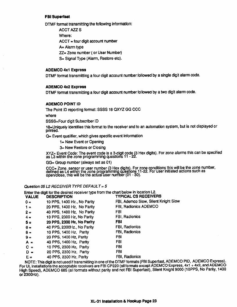
&estion 05 L2 RECEIVER TPE DEFAUL T = 5
Enter the digt for the desired receiver tWe from the charf below in location L2.VALUE DESCRIPTION TVPICAL CS RECEIVERSo= 10 PPS, 1400 Hz., No Parity FBI, Ademco Slow, Silent Knight Slow1= 20 PPS, 1400 Hz, No Parity FBI, Radionics ADEMCO2= 40 PPS, 1400 Hz, No Parity FBI4= 10 PPS, 2300 Hz, No Parity FBI, Radionics5= 20 PPS, 2300 Hz, No Parity FBI6= 40 PPS, 2300Hz., No Parity FBI, Radionicse= 10 PPS, 1400 Hz, Panty FBI, Radionics9= 20 PPS, 1400 Hz, Parity FBIA= 40 PPS, 1400 Hz, Parity FBIc= 10 PPS, 2300 Hz, Pafity FBID= 20 PPS, 2300 Hz, Parity FBIE= 40 PPS, 2300 Hz, Parity FBI, Radionics
NOTE: This digit is not used if transmitting in one of the DTMF fomats (FBI Superfast, ADEMCO PID, ADEMCO Expm!ss).For UL installations the acceptable receivers are FBI CP220 (all formats except ADEMCO Express, 4x1 +4x2, and ADEklCOHgh Speed), ADEMCO N5 (all formate without parity and not FBI Superfaet), Silent Knight 9000 (I OPPS, No Party, 14C10or 2300Hz).
XL-31 Inefslletlon & Hmkup Page 23

Ouestion 05 L3 - PULSE TYPEI DIALER DISABLU SPLIT REPORTING Default = 1
Enter the digit for the desired message length from the chart below in location L3.o= US Pulse1
2:3=4=8=9=A=B=
Touch ToneEuropean PulseSuperfast Touch-toneDialer DisableUS Pulse, Split RepoflingTouch Tone, Split ReportingEuropean Pulse, Sptit RepotingSuperfaat Touch-tone, Split Repoting
WHERE:
DIALING FORMAT - Specifies how this control panel will perform outgoing dialing over the telephone line connected tothe control panel (touch-tone, US Pulse, or European pulse format). Note: 1) Supeflast Touchtone is a faster transmissionof the touch tone frequencies and may not be accepted in all telephone exchanges. 2) The European daler option has notbeen tested for UL Installations.
DIALER DISABLE: This option will turn OFF the digital dialer making the control a local panal. The dlalerdiaable selectionshall not be selected for UL installations.
SPLIT REPORTING - If split repotiing is enabled then alarms, rastores and troublas will be reported to CW1, andopenings/cloainga will be transmitted to CS#2,
Question 05 L4- SYSTEM OPTIONS Defau/t = 4
Enter the digit for the desired system options from the chart below in location L4.o= Zone 12 Slow, Restore After Bell1= Zone 12 Slow, Restore Follows Loop4= Zone 12 Slow, Swinger Shutdown, Restore After Sell5= Zone 12 Slow, Swinger Shutdown, Follows Loopa. Zone 12 Fast, Restore After Bell9= Zone 12 Faat, Restore Follows Loopc= Zone 12 Fast, Swinger Shutdown, Restore After BellD= Zone 12 Faat, Swinger Shutdown, Restore Follows Loop
Where:
ZONE 12 FAST - Indic@es whether zone 12 will be a faat loop response zone on open. If selected then the response ofzone 12 will be appmx. a -10 Msec. If zone 12 Is defined as a fast zone then trigger number 3 cannot be used.
Restore After Sell Restores will be transmitted after the loop has returned to normal after bell cutoff, or upon systemdisarming regardless of the loop status,
Restore Follows Loop This option will transmk restores immediately upon zone restoral while the system is Armed, orupon system disarm regardless of the loop statua.
Swinger Shutdown. This feature allows individual zones to activate the dialer only three times within an arming cycle.If selected, awlnger shutdown appllas to controlled zones while the system la armed as well as 24hr, audible alarm zones.After the third activation wlthln the arming cycle, another zone violation will transmit the system trouble event followed by thezone wde and subsequent actlvationa within the same arming cycle will not transmk.
XL-31 Installation & Hookup Page 24

QUESTION 06 KEYPAD CONDITIONS DEFAULT= 9C01This question contains four locations for vatious keypad definable optbns
Question 06 L 1- KEYPAD CONDITIONS/. Reset //rrstant Arming DEFAULT=
This location specifies which of the keypad emergency condilons are active as shown in the chati bebw:
8=9=A=B=c=D=E=F=
Silent Keypad Panic, Silent Keypad AuxAudible Keypad Panic, Silent Keypad AuxSilent Keypad Panic, Audible Keypad AuxAudible Keypad Panic, Audible Keypad AuxSilent Keypad Panic, Silent Keypad Aux, * ResetAudible Keypad Panic, ~lent Keypad Aux, ● ResetSilent Keypad Panic, Audible Keypad Aux, ● ResetAudible Keypad Panic, Audble Keypad Aux, ● Reset
Where:
Keypad Penic The keypad panic rendition (depression of the. and # keye) can be selected for audible or ailerrt respnae.Central station transmission will depend on the value entered in question 24 loca~ions 1 and 2.
Keyped Aux The keypad auxiliary condition (depression of the 1and 3 keys) oan be seleafedforaudlble orsllenf reaponae.Central station transmiaaion will depend on the value entered in question 27 locations 3 and 4.
● Reset This option indicates that depression of’ from the keypad can reset the following wndltlons: sounder, and alarmmemory.
NOTE: The Keypad Fire condition (7& 9 from the keypad) is always audible, with Central Station transmission determlrrl~by the entry in question 27 locations 1 and 2.
Question 06 L2 - PHONE LINE FAILURE OPTIONS DEFAULT= C
This diait determines the amount of time reauired for detection of telephone Hnefailure and whether the keypad sounder
30 Second Phone Knefailure, Bell on failure30 second Phone line failure, sounder on failure30 second Phone line failure, Bell& sounder on failure60 Second Phone line failure60 Second Phone line failure, Bell on failure60 second Phone tine failure, sounder on failure60 sewnd Phone line failure, Bell& sounder on failure90 Second Phone tine failure90 Second Phone line failure, Bell on failure90 semnd Phone line failure, sounder on failure90 semnd Phone kne failure, Bell& sounder on failure120 Second Phone line failure120 Second Phone fine failure, Bell on failure120 semnd Phone line failure, sounder on failure120 semnd Phone tine failure, Bell& sounder on failure
and bell w~l be activated.o= Disable Phone Line Failure Detetion1=2=3=4=5.6=7=8=9=A=B=c=D=E=F=
NOTE: Do not use Bell On Failure for UL installations.
The actual duration of phone line failure detection time is dependent on the characterbtlcs of the telephone Ilne at llhtllocation. To determine the duration of phone line failure time, a test Ie required.
XL.31 Installation& Hookup Page 25

@estion 06;3 QUICK COMMANDS/ARM ONL Y/ DOOR STRIKE CODE Default = OQuick Commands Dlssblad
1: Quick Forced ArtiBypass2= Quick Arming3= Quick Forced ArtiBypass, Quick Arm4= Quick Commands Disabled, Arm Only User5= Quick Forced ArWBypass, Arm Only User6= Quick Arming, Arm Only User7= Quick Forced ArWBypaas, Quick Arm, Arm Only User8= Quick Commands Disabled, All Users ~rike9= Quick Forced ArWBypass, AII Users StrikeA= Quick Arming, All Users StrikeB= Quick Forced A~Bypasa, QuiW Arm, All Users Strikec= Quick Commands Disabled, Arm Only User, All Users StrikeD= Quick Forced ArtiBypass, Arm Only User, All Users StrikeE= Quick Arming, Arm Only User, All Users StrikeF= Quick Forced ArtiBypass, Quick Arm, Arm Only User, All Users ~rike
WHERE:
QUICK Forced Arm/Bypass Enables the quick forced arm [#2 command] andquickbypass [BYPASS ZONE commenqNOTE: The quick forced arm command shall not be selected for UL installations.
QUICK Arming Enables the quick arming command [#l].
ARM ONLY USER - If this option is selected then user number 29 will be dedicated as an arm only (makf) code. Thismeans that this user code is capabla of arming the system only. The user mde canmt be used to disarm the ayatem, If thisoption is not selected then user numbsr 29 will act as a nomal user code.
ALL USERS DOOR STRIKE - If this option is selected than all of the user males can be used to acf~ate any t~eredefined as a door strike trigger, If this option is selected then any user can activate a door strike triggerthmughthe folbwingmmmand , # 9 [USER] [Trigger number].
If t~s option is not selected then user number 28 will be the dedicated system door strike code, Hsny of the triggers aredefined for door strike. In this mode, entry of user code 28 will activate the first trigger detined as door atrfke. In addition, user28 cannot be used as an ordnary user code, unless there are no door strike triggers defined.
Question 06 L4 CS Test Interval Default= 1
This question~=dicates the method of CS Test transmission as follows24 Hour Test by Event 9 =90 Day Test by Time
1= Weekly Test by Event A = Waekly Test by Time/Event2= 27 Day Test by Event B =27 Day Test by TimelEvenf3= 60 Day Test by Event C =60 Day Teat by Time/Event4= 90 Day Test by Event D. 90 Day Tea by Time/Event5= 24 Hour Test by Time8= Weekly Test by fime7= 27 Day Test by Time8= 60 Day Test by time
Where:
Teat Interval - Select daily (24 hour), weekly ( 7 days), 27 day, 60 day or 90 day.
Test by Time Indicates that system test signals (if selected) will be sent at the time specified in question 28. The intewaldepends on the test interval selected.
Teat by Event This indicates that each event transmitted will restarfthe teet timer. For example, Ma daily signal is selectedand the Iaat signal was transmitted at 2:15AM then a test signal will be sent the following dsy at 2:15 AM if m other events~ere transmitted. Each subsequent transmission will reset the test timer.
Tees by EventfTlme Test signal will ba transmitted at specific time (defined in queafion 28) after the programmed numberof daya unless day counter is reset by an event. Esch event transmitted reatarfs the fimar. Esample: If 60 day test by eve~meis selected then a test signal will be sent after 80 days of inactivity at the time programmed in questbn 27.
XL-31 Inetslletlon & Hookup Page 28

QUESTION07 MISC OPTIONS DEFAULT= 3026Question 07 LI Siren Driver/Be//Output Default= 3
This digit defines whether the system will uti~ze the buik in siren driver or have a conventional bell output. If the Sirtlndriver is selected then the sounds for fire and burglary condtions will be selected as ehown below:
o= Bell Output1= Steady Burg, Steady Fire3= Euro Sweep Burg, Steady Fire5= Steady Burg, Euro Sweep Fire7= Euro Sweep Burg, Euro Sweep FireB= Sweep Burg, Steady FireD= Steady Burg, Sweep FireE= Euro Burg, Sweep FireF= Sweep Burg, Sweep Fire
NOTE: If the built iri siren driver does not provide sufficient sound for the installation, then program this opton for belloutput and utifize an external eiren driver. Select “O Bell Output for all UL Listed commercial applications.
Question 07 L2 AUTO-ARMING OPTIONS Default= O
This digit indicates various auto-arming options. If the eyetem ie auto armed, thie digit will select whether the system willarm in the AWAY, STAY INSTANT or STAY INSTANT modes. In addition, an optional audible warning can be generated hNOminutes prior to the auto-arming time.
0= Auto Arming Disabled1= Auto Arm AWAY, No audible warning3= Auto Arm AWAY, Audible warning5= Auto Arm INSTANT, No audible warning7= Auto Arm INSTANT, Audible warning9= Auto Arm STAY, No audible warningB= Auto Arm STAY, Audible warningD= Auto Arm lNSTANT/STAY, No audible wsmingF= Auto Arm lNSTANT/STAY, Audible warning
NOTE: Do NOT select Auto Arm for UL installations.
Question 07 L3 TIME SET USER CODE, AUTO UNBYPASS, DISP BYPASS, BYPASS RESTRICTION D8fauff =:?
Select the desired options from the chart below:o= Ueer Code Required to set ~mes1= User code not Required to Set Times2= User Code required to Set Times, Auto Unbypass3= User code not Required to Set ~mee, Auto Unbypsss4= User Code Required to eet Times, Armed ByPass DisPlaY5= User code not Required to Set ~mes, Armed Bypass Display6= User Code required to Set Times, Auto Unbypaee, Armed Bypaas Display7= User oode not Required to Set Times, Auto Unbypaes, Armed Bypass Display
This digit defines the following Syetem paramete~
USER CODE REQUIRED FOR TIME ENTRY. This option indicates whether the W command (time entw), #7 wmi~(display time) or #8 command (dsplay suto arm time) requires entry of a vatid user code.
AUTO-UN BYPASS- If this option is eelected then all bypaases will automatically be removed upn disarming the system.
ARMED BYPASS DISPLAY- Thie option indicateethat bypasses will be displayed on keypsds when the system is a~18d.
XL-31 Inatsllatlon & Hookup Page 27

@estion 07 L4 NUMBER OF RINGS, BYPASS STAK BELL TEST Defauff. 6
0-1=2=3=4=5=6=7=6=9=A=B=c=D=E=F=
Mere:
Remote Access Oisabled5 Rings For Pffikup10 Rings For Pickup15 Rings For PickupNo Bypass on Stay Arming, Remote Aaess DisabledNo Bypass on Stay Arming, 5 Rings For PckupNo Bypass on StayArmlrrg, 10 Rings For PickupNo Bypass on Stay Arming, 15 Rings For PickupBell Test At Arming, Remote Ameas DisabledBell Test At Arming, 5 Nngs For Pi&upBell Test At Arming, 10 Rings For P@kupBell Test At Arming, 15 Rings For PickupBell Test At Arming, No Bypaes on Stay Arming, Remote Access DisabledBell Test At Arming, No B~ass on Stay Arming, 5 Rings For PickupBell Test At Arming, No Bypass on Stay ArmiW, 10 Rings For PickupBell Test At Arming, No Bypass on Stay Arming, 15 Rings For Pickup
RING COUNT Determines the number of rings required by the wnfral panel to pickup forremctecommunicafion pupses.The number of rings should be set to a value which does not interfere with the telephone at the panel location. To dssbleremote Wmmunications select one of the options labeled “Remte Access Msabled”. The options for ring count are O(Remoteawess disabled), 5, 10 or 15.
NO BYPASS ON STAY This option spectiies that bypasses will not be transmitted upon Stay arming. If this option is notselected then bypasses will be transmitted for each interior zone that has been bypassed with the STAY arming. Note:Bypasses will only be transmitted i there is a bypass code defined (see question 26).
BELL TEST AT ARMING If this option is selected the bell will be ativated for ons semnd upon successful arming. Thisoption is required for UL Commercial Burglary applications.
QUESTfONOSACCOUNTNUMBER1 DEFAULT= 12S4
Enter the three (3) or four (4) digit subscriber account number for Central Station phone number 1 in locations LI-L4.
If a three(3) digit number is used then enter an A in loca~an L4.
Vatid entries are O-9,and B-F. The value A is interpreted as the null value for account numbers.
QUESTION09 ACCOUNTNUMBER2 DEFAULT= AAAA
Enferthe three(3) or four(4) d~it subscriber acmunt number for Central Station phone number 2 in locations L1-L4.
If a three(3) dgif number is used then enter an A in location L4.
Vahd entries are O-9,and B-F. The value A is inte~reted as the null value for account numbers.
If the second phone number is not used this question can be left as facto~ defaulted.
WIS ACCOUNT NUMBER MUST BE ENTERED IF YOU HAVE PR~RAMMED A SECOND RECEIVER PHONENUMBER FOR BACKUP OR SPLIT REPORTING.
XL-31 Installation & Hookun Paae 28”

QUESTION10 SYSTEMTIMEOUTS
There are 4 locations (Ll -L4) within this question which define various system timing options as follows
LI = Entry Delay 30 semtisL2 = ExK Delay 60 semndsL3 = Burglary Bell Cutoff 15 minutesL4 = Fire Bell Cutoff No Cutoff
Westion 10 L 1- ENTRY DELAY Defauff = 3
Enter the desired entry delay time in 10 semnd increments. The valti range of input is 1- F, w~h 1 indicating a 10 eeoomdentry delay and F indicating 150 seconds. For UL apphcations the maximum enfranw delay shall not exsasd ~ seconds forhousehold applications or 15 seconds for commercial burglary applioafions.
~estion 10 L2 - EXIT DELAY Defauff = 6
Enter the desired exit time in 10 seaond increments. For UL appti~tions the maximum ext delay shall not exceed (Wsmnds.
The va~d range of input is 1- F, wth 1 indicating a 15 se~nd exit delay and F indicating 150 semnds.
tiestion 10 L3 - BURGLARY BELL CUTOFF Defau# = 5
Enter the desired bell wtoff time on alarm mndiions for burglary and panic in three minute intervals. The va~i range ofinput is 1- F,wfih F indicating an infinite burg bell cutoff. Example 3 =9 minutes. For UL installations inmmmercialapp~ibnsthe minimum bell cutoff shall be 15 minutes, or 4 minutes for househoti burglary apphcations.
@estion 10 L4 - FIRE BELL CUTOFF Defaufi = F
Enter the desired bell cutoff time for fire condtions in three minute intervals. The.va~i range of input is 1 -F, Wh Findicating an infinite fire bell cutoff. Example 3 = 9 minutes. For UL Installations the minimum fire bell outoff time shall bs)4minutes.
XL-31 fnatallatbn & Hookup PagaM

8.1. ~Ouestkms 11-22 represent all the options related to programmable zones 1-12. The U@ksare deecfibad babw
L1 Zone Supervision Type
L2 Zone Type
L3 L4 CS Transmission Codes
L 1Zone Su~wision Tyw. EOL Supervised Inteflor Zone
1= Normalfy Open (NO) Inferior Zone2= Normal~ Closed (NC) Inlerbr Zone
4. EOL Supervised Instant Zone5= Normally Open (NO) Instant Zone6. Normally Closed (NC) Instant Zone
8= EOL Supewised, 24 Hour Zone or Keyewitoh9= Normally Open (NO), 24 Hour Zone or KeyswhchA= Normally Closed (NC), 24 Hour Zone or Keyswifch
c= EOL Supewised Delay ZoneD= Normally Open (NO) Delay ZoneE= Normally Closed (NC) Delay Zone
NOTE: EOL Supervision must be programmed for all UL insallatbns. If EOL Suparvisbn is spactied then the end of lineresistors supptiad with the control panel must be used on these zones.
L2ZONE WPE -
Select the zone type based on whether the zone is a controlled (burgla~) zone or 24 hour zone.
o= Burg. Zone (No Other Options)1= Restore2= Day Zone3= Restore, Day Zone4= Chime5= Restore, Chime
6= Day Zone, Chime7. Restore, Day zone, CMme6= Dialer Delay9= Restore, Dialer DelayA= Day Zone, Dialer DelayB= Restore, Day Zone, Daler Delayc= c~me, Dialer DelayD= Restore, CMme, Dialer DelayE= Day Zone, CNme, Dialer DelayF= Restore, Day zone, Chime, Dialer Delay
0= Audble 24 Hour Alarm1= FIRE2. Audible 24 Hour Trouble3= Keyswifch4= Audible 24 hour slam, restore5= Fire, Restore6= Audible 24 hour trouble, Restore
6= Silent 24 hour alarm
A= Silent 24 hour trouble
c= Silent 24 hour alarm, ReWore
E= Slent 24 hour trouble, ra~ore
ZONE TYPE DESCRIPTfONS
Zones 1-12 can be programmed for any one of the following zone types
BURGLARY (CONTROLLED) ZONES
DELAY This is the industry stama~ ex.tient~ zone. When the Sysfem is a~~ exfi
time begins. After exi expires, any subsquent violafiin of this zone will beginentry time. If the system b not disarmed within the programmed entry time analarm will occur. The keypad sounder will annunciate steadi~ durtng entry time,
XL-31 Inatallatbn & HWup PagaSO

INTERIOR
INSTANT
BURGLARY ZONE OPTtONSRESTORE
CHIME
unless there had been an alarm condition, at which time K will pulse. Defeyzones will activate instantly when the system is armed using the INSTWTmode.
All interior zonee have exit delay time upn system arming. Furthermore, alllinterior zones will have entry delay time if a delay zone is violated first. If thiszone ia violated first however,it will generate an immediate alarm.
Interior zones will automatically be bypassed if the system is armed in the STAYmode.
This zone type (sometimes known aa PERIMETER) will generate an alarmwhen violated while the system is armed.
If this option is selected on a burglary zone, then the programmed restore codlewill be repofied upon bell mtotf, assuming the loop is restored. The restore COdlewill also be repofied if the system is disarmed durfng an alarm.If this option is selected the keypad sounder will annunciate for 1 second whelnthis zone ia violated in the disarmed mode.
DIALERDELAY If this option is selected the system will allow a 15 se~nd delay before diallmg,allowing the end user to ABORT the tranamiasion. If this optbn is not selsofad,anyalarm condtion will resukin anlmmediate transmlssbn that ~n~ttaa~tied. NOTE: For UL installafiins dialer delay may not be used.
DAY FEATURE If a zone wkh t~a option is violated while the system Is DISARMED, the keypdaounderand zone LED will pulse for ae long as the violation remains. In addiibln,the SYSTEM TROUBLE CODE will be transmitted to the central station. ~lESOUNDER CAN BE SILENCED through entry operation of any valid userde.
While the ayatem Is armed, a DAY zone will act as an alarm when vblatsd.
24 HR ZONES— FIRE FIRE zones contain Fire Verification Logic. Upon detection of the first vlolatbn,
emoke detector pwer will be reset for a pertod of 8 seconde. After this timeperiod, @wer la restored. For a period of 5 eeconde the fire zone will not twscanned allowing the smke detectors to aetfle. Future violations within a twominute period will reeult in a PULSING BELL OUTPUT, RAPID PULSING ZOhlELED,and IMMEDIATE tranamiaaion to the CS. Hre aignala cannot be *fled.
Enfv of any valid user mde will silence the sounder and bell. EntW of a vallkfuser code for a second time will reeet smoke detector ~wer and clear alarmmemo~. If the syetem detecfa that the tire zone is still violated within 2 minuf13sof pwerreset, the zone LED will pulse slowly to indicate a tire trouble.Thereafter, smoke detector power will be reset every 4 minutes automaticalwin an attempt to clear the fire zone.
[n the event the fire zone experiences an open, the system indicates tire troutlleby pulsing the keypad zone LED and sounder slowly. The system trouble wj6( followed by the zone code) will be repotied to the CS.
Any vatid user number silences the keypad.
NOTE:Fire Zones cannot be bypassed. 24 HOUR TROUBLE muet NOT Ikused for fire~urglary protection. A 24Hr alarm zone must not be used ilorpetimeter protection.
24 HR ALARM This zone type is shays active, independent of the system arming status.Programming options include audible (STEADY BELL) or silent (NO BELL orkeypad indications), with or without restore codes. Upn violation the zoneLEDS will pulse rapidly (audible zones only) and an immediate CS transmissionwill occur which cannot be aborted.
24 Hour Alarm zones can be bypassed, however they cannot be unbypass~lHa violation exists on thazone terminala.
XL-31 Installation & Hookup Page31

24 HR TROUBLE This zone type is akays ac!~e, independent of the system aming etatua.Programming opfiins include audible (PULSING KEYPAD SOUNDER) orsilent, wkh or whhout restore cedes. Upn violation the zone LED will pulseelowly. Trouble ~ndfiion must exist for 15 seconds before a transmission willoccur. The keypad dbplay and eounder will olear upon zone metoral.
24 Hour Trouble zones can be bypassed, however fhey cannot be unbypassedit a violation exists on the zone teminals. Any Valid UserlD silences the keypad
KEYSWITCH Keyswtich zones will toggle the sming statue of the system. NOTE KeyswtichZone operation has NOT been investigated by Underwriters Lakratories.
ZONE ALARM CODESLocations L3 and L4 of the zone questions represent the alarm mde that will be reported to the central efatbn.
zOneS WilltranSMti to the Central Station Unless these ~gtis are defined as w for any in~vidual zone, or the bcal dialeroptbn is selected in question 05. Based on the tialer format selected enter the slam cede as follows;
STANDARD FORMAT Enter the desired single digit alarm cede in location L3. The value placed in L4will net be used.
Example: Desired transmission 1232(account 123, alarm mde2).
Enter a 2 in location L3 of the zone. Any value placed in L4 will be not be used.
EXTENDED: Enter the desired first dig~ of the alarm cede in location L3. The sewnd digit in L4.
Example: Desired transmission 12333334
Enter 3 in L3, 4 in L4.
PARTIAL EXWNDED,: Enter thedesiredd tiinhth locations L3and L4. Thiswiil generate asiWleP ~~round alarm transmission andan extended ransmlsslon forallsyefem ~ndtions suchas reefores.
Example: Alarm 1233Restore 123 E
EEE 3Enter 3 in L3 and L4.
4x2: Enter the desired first digit of the alarm mde in location L3. The sewnd digit in L4.
Example: 476532 Enter 3 in L3, 2 in L4.
FBI SUPERFAST The two digits zone type L3 L4 will be transmitted as the zone code.
ADEMCOEXPRESSFORMATS: In the 4x2 format L3 - L4 will be transmitted, in the 3x1 format only L3will be transmitted.
ADEMCO POINT ID (PID) Format:ThePID format transmits the following information:
The Point ID reprting format: SSSS 16 Q~Z GG CCC
where
SSSS=Four digit Subscriber ID
16=Uniquely identifies this format to the receiver and to an automation system, but is not displayed orprinted.
Q= Event qua~ier, which gives specific event information
1= New Event or Opening
3= New Restore or ClosingWZ= Event Code: The event mde is a 3digfi wde (3 Hex digtis). See L3 below.
GG= Group number (fixed as 01)
CCC= Zone or Sensor number (3 Hex digits). Zone Alarm is defined as L4. (Event reports) or User #(QpeWClose events)
XL-31 Inetalfatfon & H@kup Paga 32

L3 PID EVENT Code
The PID event @de transmitted (shown as W in PID example) depends on the ~ of event @ tftStable tisted below:
Value Burglary Zn Fire Zrs 24Hr Alerm 24HrTroubho 122Silentpanb 110FireAlarm 100 Medioel 100MediA1 123Aud. Panic 111Smoke 101PendantXmh12 silent2 130Burglary 112~mbustbn 120PanicAlarm 123Aud Pank3 131Perimeter 1t3 Water Fbw 122SilentPanb 137Tamper4 132Intedor l14Heet 123AudlblaParsb15024Hr~rg5 13324Hr.Alarm 115PullStation 130Burglaw 15SHeet*s 134EntryExit l16Dua lW 24 Hr. Alarm 155FoilBreak7 135Day~ight 117Flema 135DayNQht 15SDayTWS.s 136 Outdoor 140Gen. Alarm 13?Tamper 15SHhh Temp.9 137Tampar 15024HrN/Brg 140Gsn. Alarm 159LowTamp.A 140Gen.Alarm 15SHighTemp 15024GasDetd 300 SystemTrbb,B 144Snsr.Tamper159LowTsmp 151GaaDatd 301 AC Loasc 155Foil Braak 200 FireSensor 152Refrigeratbn 302 L. SP. Bet.o 156DayTroubls 201 L. WaterPr. 153 HeatLose 310 Grid.FaukE 202 LowC02 164WaterLe* 37SFireTrbl.F 203 ValveSnsr. 155Foil Bra* 380 Snsr.Tbl.
Example:For a burglaryzone,entar a 2 in L3 to definethe zone se anevantde d 130.
L4 Zone Seneor No.
Enter the de ired zon number t be ~ran mMed t the oentral atatlon info L4 of h zone MSMbOr.~is @61?ehown aeC C in the ormat expanatlon.*rtferO-?, the zone numberenteredw~ll~tmnsMW i~o
decimalformat.
QUESTION 11 ZONE 1 Default =
QUESTION 12 ZONE 2 Default ❑
QUESTION 13 ZONE 3 Default =
QUESTION 14 ZONE 4 Default =
QUESTION 15 ZONE 5 Default =
QUESTION 16 ZONE 6 Default ❑
QUESTION 17 ZONE 7 Default =
QUESTION 18 ZONE 8 Default =
QUESTION 19 ZONE 9 Default =
QUESTION 20 ZONE 10 Default ❑
QUESTION 21 ZONE 11 Default =
QUESTION 22 ZONE 12 Default=
C031
0032
40ss
4034
4035
4036
4037
4038
4039
4030
403B
403C Zone 12ean be programmedfor FeatZonQma~nwl
XL.31 Inatallatforr & t400kup Page 3S

QUESTION ~ AMBUSHIAC LOSSThere are 4 locations L1-L4 in this question. L1 - L2 is the alarm code that will be transmitted on AMBUSH. If an am~sh
code is defined then user number 30 is the ambush code. L3 - L4 is the AC LOSS CODE. The same rules for programmingregarding dialer format apply here. If either of these transmission are not desired, program their respective Iocatiins AA.
AMBUSH transmissions are immediate and not ahrfable, AC LOSS is reported 15 minutes after detecfbn.
LI - L2 AMBUSH AAL3 - L4 AC LOSS AlNOTE: If the first digit of AC loss (L3) is an A, then the second digti (L4) will detemine whether thekeypad sounder will activate u~n loss of AC, EntW of A into the second field (L4) will cause the keypadsounder to be inactive during an AC failure (note vieual indications will remain unchanged).
AMBUSH CODE PID FORMAT
If PID format is selected then program L1 with the following values to select the desired PID code;
ULuF PIDCode De~o 100 Medical1 101 Pendant Transmtier
2 110 fire Alarm3 111 Smoke4 112 Combustion5 117 Flamee 120 Panic Alarm
7 1218
Duress122 Slent Panic
9 123 AudiblePanicA 130 BurglaryB 133 24 HourAlarmc 140 GeneralAlarmD 150 24 HourNonBurglaryE 130 Burglary
130 Burgla~AC LOSS TY;ES (L3)
If transmitted in PID format, select the desired event code in L3 from the table below.
~24 HourAlarm
1 140 GeneralAlarm2 150 24Hr, Non-Burg.3 300 Sys.Trbl.
4 301 AC LOSS
L4 will represent the desired zone code to be transmitted for AC loss.QUESTION 24 PANIC/LOW BA~ERY
Thera are 4 locations L1-L4 in thie question, L1 - L2 is the alarm code that will be transmtied on keypad PANIC. L3 - L4is the LOW BA~ERY CODE, The same roles for programming regarding dialer format apply here. If either or bth of thesetransmissions are not deeired, program their respective Iocafiins AA.
PANIC transmission are immediate and not abortable.
LOW BATTERY transmissfona will be reported 4 minutes after detection. LOW BA~ERY RESTORE CODE will bereported WITHIN 4 minutes after detection of GOOD BATTERY mndfiion.
CATIONS DEFAULTSL1 - L2 PANIC 22L3 - L4 LOW BATTERY AA
POINT ID FORMAT
If transmitting in PID format then L3 will represent the event code as shown in the table below:
~m
1 140 GeneralAlarm2 150 24Hr,Non-Burg.3 300 Sys.Trbl,4 302 LowSys Bat.5 309 Batte~ Test Fail
L4 will repreeenf the zone mde transmitted to the central station.
XL-31 Installation & Hookup Page 34

QUESTION 25 OPEN/CLOSE, CANCEL, TEST CODEThere are 8 locations LI -L8 in this question.
Question 25 L1 OPENING CODE for users 1-15. L2 is the single digit CLOSING CODE for users 1-15. Entry of AA itiothese two locations means that openings and closings are not desired. If a dialer format other than statia~ is programmedthen the second digit transmitted will ba the user number.lf PID format is used then see chart below for entries of the eventwde and the user numbar will ba the actual user number.
Question 25 L3 is the single digit OPENING CODE for users 16-30. L4 Isthe single digit CLOSING CODE for users l&30.Entry of AA into theee two locations means that openings and closings for users 16-30 will utilize the codes defined in LIand L2. If a dialer format other than standard is programmed then the second digit transmftfed will be the ueer number.lf PIIDformat is used then see chati below and tha user number will be the actual user numbar.
@estion 25 L5 Camel Code (Usars 1 -15) A cancel code can be transmitted to the Central Station i after violatbn ofa wntrolled zone, a user code is entered. If the zone is still vhlatad entry of a user code will transmfi the cancel code. Thisis the code transmitted for user numbere 1-15. If the zone is programmed for restore then the rastore code cenbe transmittedwhen the loop status has returned to normal. Entry of A in this fiald indicates that cancel males are not transmiffad. In formalsraquiting two digfis, the user numbar functions as the semnd dgif.
Question 25 L6 Cancel Code (Users 16- 30) This is similar to the previous location except this transmits the carnal codeforusars 16-30. Ent~of A indicatasthat cancel the cancel @de for all ueers will beobtainedfromthe informafionprogrammedin L6.
Question 25 L7 - L8 TEST CODE These locations indicate the desired Central Station mde fortransmisslon of the systemtest rode. The frequency and type of testis defined in question 06 location 4. Entry of AA indicates that system testis rs)ttransmitted.
s DFFU
L1 OPENING CODE (Users 1-15) A
L2 CLOSING CODE (Users 1-15) AL3 OPENING CODE (Users 16-30) A
L4 CLOSING CODE (Users 16-30) AL5 Cancel Code (Users 1- 15) AL6 Cancel Code (Users 16- 30) AL7 - L8 TEST Coda M
OPEN/CLOSE POINT ID FORMAT
If transmitting in PID format, then LI - L4 will datermine the OPEN/CLOSING event codes to be triinsmiffed as shown inthe table below:
~Opsn/Closs
1 401 Ussr OiC2 402 User Group3 403 Auto-Arm4 404 Lateto O/C5 405 DeferredO/Ce 407 RemoteArmO/C7 40s Quick Arm Closes 409 KeyswltchO/C
QUESTION26 BYPASS/RESTOR~ROUBL~AMPER CODEThere are four(4) Iocatlona L1 - L4 in this question:
Quastion 26 LI ia ‘the single digit systam BYPASS CODE re~fled to tha central station Ha zone Is bypassed, UPONARM ING.Entry of an A means that bypassas are not transmitted. If a two digk dialing fomat has been selected then ttleBypass code will be followed by the programmed eecond digit of the zones code. For point ID format see than that folb~fsfor available options.
Question 26 L2 Is the single digit system RESTORE CODE repofied to the central station. Restores will be reported f{jrWrglary or 24 hour zones w~ch have been programmed wtih the restore option. Entry of an A means that restores are nMtransmitted. If a two dlgh dialer format has been programmed then the restore code will be followed by the programmedsacond dig~ of the zones code.
Question 26 L3 is the single digit system TROUBLE CODE reported to the wntral station. This wde will be reprted cmDAY TROUBLE and any FIRE TROUBLE, If a two digit format has been programmed then this ma will be folbwed byttlesecond digit of tha respective zones code. Entry of A indicates that tmublea are not transmlffed. If plD format is us~ thtlnselect from the following options:
XL.31 lnetailetlon & Hmkup Page *

Vtluo PfD ~ Deecrlptlono 1ss 24 Hour Alarm1 135 DayrN@ht2 13? Tamper3 150 24 Hour WBurg4 155 Foil Break5 156 Day Trouble6 300 Syetem Troubles7 373 Rre Trouble6 360 Sensor Truubfee9 363 SeneOrtamper
Oueetion 26 L4 ie the keypad tamper wale. If 21 digits are entered through the keyped wkhout entry of a va~i user tie,then the keypad eourtder will activate until a va~i user de is entered. If a keypad tamper code ia entered then it will be~m~~edtothe. nfe ral Station. If a two digit CS transmieebn de ie aelacfed (example 4x2 or extanded) then the trouble
e WI be the first dgh transmtied.
~~L1 BYPASS A L2 RESTORE EL3 TROUBLE F L4 KEYPAD TAMPER APID FORMAT (BYPASSES)lftranamiffing PIDformatthen Ll repreaants theevenfcode asshown below:
Velue PIDWdeo 5701 5712 5723 5734 574
De=riptlonZone SypassedFireZone Bypassed24 HourZone SypsssedBurglaryZone SypaeeedGroupsypass
QUESTION 27 KEYPAD FIR~ KEYPAD AUX. DEFAULT :1123There are 4 Iocafione LI -L4 in this queefion. L1 - L2 is the code that will be transmitted upon activation of the keypad fire
wndition (preesing the 7 & 9 keye on the keypad). TNe code can vary from any of the zones which are programmed aa tire.NOTE: To inactivate the keypad fire condition enter AA.
L3 - L4 ie the code transmitted to the CS for keypad aux, condnion ( 1 & 3 from the keypad) . To dseble the ke~adauxiliary condiion enter ~. The keypad auxiliary mndtion can be silent or audible baeed on the queetion 06 location 1.
~KPAD FIRE 11
L3 - L4 KPAD AUX 23PID FORMAT (Keypad Condtions)
If transmitting in PID zone format, L1 and L3 will epecify the event mde transmitted from the table bebw.L2 and L4 defines the zone number transmtied for PID format.
Value PIDCode Descriptiono 100 Medical1 101 Pendant TranamNer2 110 Fire Alarm3 111 Smoke4 112 timbustion5 t17 Flame6 120 Panic Alarm7 121 Duress6 122 Silent Panic9 123 Audible PanicA 130 Burglarys 133 24Hr Alarmc 140 General Alarm
24Hr Alarm
QUESTION 28;EST %;E DEFAULT =04 00If the mntrol panel transmits a system test at a epectic time of day enter the hour and minute in mi~~arytime (24 hour
C&k) aa follows:
LI L2 Hour of day [00 - 24] L3 L4 Minute wthin hour [00 - 59]
Example: 5:30 PM= 1730
XL-31 Installation & Hookup Page 3S

QUESTION 29 Trigger 1 & 2 DEFAULT= OCO1The control panel contains 4 voltage level output triggers. Enter the desired tfigger type for each olutput trigger (see table
below).
LI L2 Defines Trigger #1 Default = Strobe L3, L4 Defines Trigger #2 Default = Burglaw
QUESTION 30 Trigger 3 & 4 DEFAULT = 021 BThe mntrol panel contains4 voltage leveloutput triggers. Enterthe desiredtrigger type for each output trioger.
LI L2 Defines Trigger #3 Default = Hre L3 L4 Defines TrigOer #4 Default = Zone Reset
NOTE: Trigger #3 cannot be used if zone 12 is being used for Fast ResWnse.
TRIGGERTYPESCODE0001 [Trigger 2 Default]02 (Trigger 3 Deafult]03040506070s09OAOBOC [Trigger1 Default]ODOEOF101112131415161718191A1e‘ [Trigger 4 Default]
DESCRIPTIONTrigger DlssbleBurglaryFireDuressKeypad Tamper24 Hour TroubleFire TroubleDay Trouble24 Hour AlarmKeypad FireKeypad AuxiliaryKeypad PanicStrobeAC LOSS
Low BatteryArmingBypasaEntryExitInstantSTAYReadyD~R STRIKE (Access trigger)Comm FailurePhone failureSounderGround StartZone Reset
ACTIONNone
Steady follows Burglary timeoutSteadv follows Fire timeout2 Semnd pauae following duress mdeKpad tamper turns an, vahd user ade turns offFollows 24 Hour troljbleFollows fire troubleFollows day trouble zone (on after 15 see)Audible follows bell, 2 sac. pulse on silentAudibla follows bell, 2 sac. pulse on silentAudible follows bell, 2 aw. pulse on silentAudible follows bell, 2 s=. pulse on eilentFollows arming light, until system dsarmFollows AC after 15 min delayFollows Low batteryFollows arming stateFollows any zone bypassedFollows entry timeFollows exit timeFollows Instant StateFollows STAY stateFollows ready state5 Semnd Pulse on entry of door etrike mcleFollows comm failure lightFollows phone failure lightFollows keypad sounderFollows diating (Trl~ger #l only)Reaeta Latched Zones (Ie glass break det.)
‘ NOTE: If Zone reset triggar (type 1B) is aelectad then depreaaion of’ from the keypad will iictivate the tfigger
QuestIon 00 INSTALLER CODE Default ❑ 4612There are 4 locationsL1 - L4 in this question. Enter any 4 digit installer code desired. This code is used to ENTER the
system programming mode via the keypad. Typically each installing mmpany would use a unique installer code in order toprevent unauthorized people from gaining access to their panels. Note: The facto~ default value for the inetallercode is 4012in locations L1-L4 respectively.
NOTE: This question is can be accessed only through the dhecf access mode, select question 00.
XL-31 Installation & Hookup Page 37

9. DATA ENTRY VIA LED BASED KEYPADS
This section describes the physical keystrokes necessary to perform keypad programming and how to interpret the datadisplayed on the LED baaed keypads during programming operaffona. This section describes opera~on through efiher theXL4612RM, XL4612SM or 7015 keypads. Actual keypad programming should be performed after mmplefiin of theprogramming sheet.
9.1. HOW TO ENTER PROGRAMMING MODEThe SYSTEM programming mode can be entered WHILE DISARMED ONLY as follows:
DEPRESS the CODE button.
DEPRESS the * button. (asterisk)
ENTER the four digit INSTALLER CODE (defauH value= 4612)
ENTER the digit 1 (Installer mode 1 = Keypad programming)
9.2. WHAT YOU SEE ON THE KEYPAD
PROGRAM MODE = READY LED:
Upn entering the installer keypad programming mode the READY LED will slowly pulse, and will continue to pulse u~lleaving this mode.
QUESTIONNUMBERS= ZONE LEDS:
As previously stated there are 42 total questions, each of which contains mutiple data entry Iocatbns.
Zone LEDS 1 through 6 display the wrrent QUESTION NUMBER (not the sDacific location within each auesfbn) aa
+2
+4XL4612RM
+s
‘EsToNNuMBERII: L
IL
XL4612SM
In the tiagram shown the question number is obtained by ADDING the values of all LEDS that are ON. TMa appfies tobath the metal and plastic versions of the keypad.
EXAMPLES:Zone 1 ON, Zones 2-5 OFF = QUESTION 01Zone 1 ON, Zone 2 ON, Zones 3-5 OFF = QUESTION 03Zone 2 ON, Zone 3 ON, Zone 4 ON, Zones 1 and 5 OFF = QUESTION14
XL-31 Instalbtbn & Haokm Page 36

LOCATION CONTENTS = Zones 9-12 Status
The zone LEDS 9-12 displays the DATA that resides in EACH location wittin the current quesfioll. Aa per the diagramand explanation abve, the value located nefl to each LED must be ADDED to calculate the total data, for each hatbnl.The following chart presents binary value LED displays for the letters A-F which may be entered in some locations of theprogram sheet.
A 10 Zone 10&12=ONB 11 Zone91012=ONc 12 Zonell &12=OND 13 Zone911 12=ONE 14 Zone lOll 12=ONF 15 Zone91011 12= ON”
9.3. HOW TO ENTER DATAThis section of the manual describes the physical keystrokes to enter the data written on the progfi~m sheet.
MOVEMENT BETWEEN QUESTIONSUpon entry into thesystem program mode quesfionnumberl is displayed.Random jumps to any question can be made by depressing the ● (astetisk)button and the 2 digit question number.
Questions can be accessed randomly or sequentially.
Example: Jumptoquesfion07 =depress*07
The proper question number will be displayed by the zone LEDS and the otherstatus LEDS will display the contents of the FIRST location In that question.
MOVEMENT WITHIN QUESTIONS Aspreviously stated thezones l-6 L~Sdlsplay thequestion nufnberafsjzones 9-12 will display the mntents (data) within each location. Movementfmm location L1 to the next location wkhin any question can be peflormed b!fdepressing the # POUND BU~ON.
The status LEDS display the Iooatlon contents as this button Is depressed.
DATA ENTRYAlter ANY location value by entering DIGITS from the program sheet, thenDEPRESS THE # BUTTON to save the information and advanoa to the nextlocation.
NOTE: Press the #key affereach entry .THE SYSTEM WILL NOT PROGRAhtTHE DIGIT UNTIL THE POUND (#) BUnON IS DEPRESSED, THEREFOREIF A MISTAKE IS MADE IT CAN BE CHANGED.
Numetic entries O-9 can be performed by depressing ttle respetive kewa~jbutton. However, entries of A-F require 2 keystrokes as follows
Depress the CODE buffonfollowed byl-eforvaluee A.F.VALUE KEYSTROKESA CODE 1B CODE 2c CODE 3D CODE 4
E CODE 5F CODE 6
Example:
Enter an A=depreaa CODE followed byl.
EXIT SYSTEM PROGRAM MODE After all programming haa been @mpleted, depreaa the STAY button to exffthe system program mode. All the LEDS will turn ON for spproximatefy 10seconds, before the system returns to normal daily operation. NOTE Keypadprogramming will automatically terminate after 10 minutes and no keystrokeshave been entered.
XL-31 lnatallatfGn & Hwkup Paga 39

The keypad will emk a beep bfween keystrokes. In addtbn a beep will begenerated mnfirming a~ancement beween queatbns nutiem,
SUMMARYOF SYSTEMPROGRAMMING
Four beeps will be generated t an invalid input is entered. Upon entry of iwtidinput you are postioned at the same quesfiin number and hafiin as prior tothe input error.
ENTER PROGRAMMING MODE CODE ● [INSTALLER CODH 1
EXIT PROGRAMMING MODE STAY -
ADVANCE BETWEEN LOCATIONS (ENTER) #
GO TO SPECIFIC QUESTION ‘ [Oues~nn Number]
Esample:” 05
Data Entry o-9
A - F entered as followq
A CODE 1
B CODE 2
c CODE 3
D CODE 4
E CODE 5
F CODE 6
10. DATA ENTRY THROUGH LCD KEYPADS
Keypad programming can also be accomplished through 7005 keypads. In addition to the normal 30 programmingqu9SfiinS, addtionai capabi~iy is available for entering the zone descriptors drecfly through the keypad.
10.1. HOW TO ENTER PROGRAMMING MODETheSYSTEM programming mode can be entered WHILE DISARMED ONLY as follows:
DEPRESS the CODE button.
DEPRESS the ‘ button. (aaterisk)
ENTER fhe four digit INSTALLER CODE (default= 4612)
ENTER the digit 1 (Installer mde 1 = Keypad Programming)
10.2. WHAT YOU SEE ON THE KEYPADU~n entering the installer keypad programming following display will appear
mThe display shows the current question number (QUES), the location wlhin the question (L:) and the current value wthin
that bcstion (DATA =). This corresponds to the programming woksheet,
XL-31 Insfalletbn & Hmkup Page ~

10.3. HOW TO ENTER DATAThis section of the manual describes the physical keystrokes to enter the data written on the program sheet.
MOVEMENT BETWEEN QUESTIONSUWnentry into thesystem program mode question nllmberl isdisplayecl.Random jumps to any question can be made by depressing the ● (asterisk)button and the 2 digit question number,
Questionscan be accessedrandomlyor sequentially.
Example: Jumptoquestion07 =depress *Q?
The proper question number will be displayed by the zone LEDS and the otherstatus LEDS will display the contents of the FIRST location in that question.
MOVEMENTWITHINQUESTIONS
DATA ENTRY
The dsplay shows the current location within each programming questiorl.Movement from locafion Ll tothenext locafion wifhinany question canbsperformed by depressing the # POUND BUTTON.
To aker the value in ANY location, enter the desired DI(31Tfrom the programsheet, then DEPRESS THE # BUTTON to save the information ad advanceto the next digit.
NOTE: THE # BU~ON m BE DEPRESSED AFTER ENTRY OFDESIRED DIGIT. THE SYSTEM WILL NOT PROGRAM THE DIGIT UNTILTHE POUND (#) BU~ON IS DEPRESSED, TH~EFORE IF A MISTAKE 1:3MADE IT CAN BE CHANGED.
Numeric entries O-9 can be pedormed by depressing tile respective keypadbutton. However, entries of A-F require 2 keystrokes as iollows:
Depress the CODE buttonfollowedbyl-6forvalues A.F.VALUE KEYSTROKESA CODE 1B CODE 2c CODE 3D CODE 4E CODE 5F CODE 6
Example: Enter an A -depress CODE followed byl.
EXIT SYSTEM PROGRAM MODE After all programming has been completed, depress the STAY button to exhthe system program mode. All the LEDS will turn ON for approximately 10seconds, before the system returns to normal daily operation. Keypadprogramming will automatically be terminated after 10 minutas and no keypadactivity.
QUESTIONACKNOWLEDGMENT The keypad will emit a beep between keystrokes. In a(jdtion a baep wiH begenerated confirming advancement be~een questions numbers. AinvaKdinput produces 4 beeps. Upon entry of invafid input you are positioned at thlesame question number and location as prior to the Input error.
XL-31 Inatallatlon & Hmkup Page 41

10.4. ZONE DESCRIPTOR PROGRAMMINGTheLCDbasedkeypsds display 12 characterzone descriptorswtich can be programmeddirectlythrough the ke~ad.
These descriptorsare enteredas programmingquestions31-42.
NOTE: These questions can only be a~essed by an LCD keypad, or the EZ-Mate Programming Devices.
The zone descriptor questions are as follows:
QUESTION DESCRIPTOR
31 Zone 1 Descriptor [Default= ZONE 1]
32 Zone 2 Descriptor [Default = ZONE 2]
33 Zone 3 Descriptor [Dsfsult = ZONE 3]
34 Zone 4 Descdptor [Default = ZONE 4]
35 Zone 5 Descriptor [Default = ZONE 5]
36 Zone 6 Descriptor [Dsfault = ZONE 6]
37 Zone 7 Descriptor [Default = ZONE ~
38 Zone 6 Descriptor [Default = ZONE 8]
39 Zone 9 Descdptor [Default = ZONE 9]
4 Zone 10 Descdptor [Default = ZONE 10]
41 Zone 11 Descriptor [Default - ZONE 11]
42 Zone 12 Descriptor [Defauh = ZONE 12]
For example to program the descriptor for zone 3 enter” 33, to access question 33.
When programming the English zone descriptors the following techniques are used to program the characters:
KEYSTROKE
o
CODEkey
INSTANTkey
7
.7
9
#9
ACTION
Insertsa space and advancesthe cursor
Movesthe curwr to the left one space
Movesthe cur-r to the rightone space
Increments the character at the cursor
Scrolls forward (UP) throughthe characterset.
NOTE: Depression of any-key will stop the scroll
Decrements the charatier at the cursor
Scrolls backwards through the character set
NOTE: Depression of any key will stop the scroll
NOTE: Available LCD keypad characters are:VWY~&(~ +-./01 23456789 ;=@ABCDEFGHlJKLMNOPQRSTUVW~
SYSTEM DEFAULT (LCD keypad only)
Simultaneously pressing the 1 &3 keys while”in programming mde inifiatee a system default. The system will then defautiand go through the reset sequence.
USER CODE DEFAULT (LCD keypada only)
The User codes can be reset to the default state by pressing the 7 & 9 keys on the LCD keypad at the same time, whilein programming mode, This will bring the user codes bati to the original defauk settings.
XL-31 Installation & Hookup Page 42

11. SYSWM DEFAUL~
The control panel is preprogrammedfromthe factorywith defauti values.Thesevalues have been seiaofadto meetttlerequirementsof a common installationand maysuit your needs.
To reloadthe factorydefault values, removeall rower fromthe system(AC& DC).NeX sho~ Tpl to Tp2, w~hshofl s~illintact reapply ~wer (AC then DC),wah 5 semnds then removeshortwhh the Wwer still applied. NIOTE:A programmiruoption existswtihin the PCDownloaderknownas DEFAULTLOCKOUT.If this option is selectedthen a systemdefauhwillnetoverwritethe CSIDor installermde potion of the program.This will preventan installerother th:ln the or~inal installerfrom taking over an aaunt without cooperation.
F F~
00 Installer Code01 Phone #102 Phone #203 Callback Number04 PBX Prefix05 Dialer Options
06 Kpad options
07 Mist
08 Account #109 Account #210 Tmeouts
11 Zone#l12 Zone #213 Zone #314 Zone #415 Zone #516 Zone #617 Zone#716 Zone #819 Zone W20 Zone #1021 Zone #1122 Zone #1223 System Codes24 System Codes25 System Codes
26 System Codes27 System codes28 Test Time29 Triggers30 Triggers31 Zone 1 Descriptor32 Zone 2 Descriptor33 ZOne 3 DeSCrlDtOr34 Zone 4 Desor[ptor35 Zone 5 Descriptor36 Zone e Descriptor37 Zone 7 Descriptor36 Zone e Descriptor39 Zone 9 Descriptor40 Zone 10 Descriptor41 Zone 11 Descriptor42 Zone 12 Descriptor
4612234~~ (none)~ (none)MA (none)3x1 Standard, 20 PPS,2300HZ, No Parity, Touch T,one,Swinger shutdown, Restore After BellAud. Keypad panic, Silent keypad Aux, Enab. Instatlt Arming,120 Sec Phone Une fail ,Quick commands disabled,24 Hour Test by ~meEuro Sweep Burg Siren, Steady Fire Sren ,No Autcl-Arming,User code req to set time, Auto Unbypass, # Rings = 10,No Bypass on Stay Arming1234AAAA (null)Entry Delay =30 sec., Exit Delay =80 secondsBurg Bell Cutoff = 15 minutes, Fire Bell Cutoff= Nc)~meoutDelav EOL Code =31lnte~or EOL Code =32Perimeter EOL Code =33Perimeter EOL Code =34Perimeter EOL Code= 35Perimeter EOL Code= 36Perimeter EOL Code= 37Perimeter EOL Code =36Perimeter EOL Code= 39Perimeter EOL Code= 30Perimeter EOL Code= 3BPerimeter EOL Code= 3CAmbush = AA (null) AC Loss= Al (no CS tranemis[sion, audible sounder)Panic =22 Low Bstte~ = AA (null)Open (ueere 1- 15)= A (null) Close(users 1- 15)= A (Null)Open (users 16- 30)= A (null), Close (users 16- 30)= A,(null)Cancel (users 1- 15)= A(null), Cancel (ueers 16- 30) = A(null),Test Code = AA (null)Bypase = A (null) Reetore = E Trouble= F Keypad Tamper= A (null)Keypad fire = 11 Keypad Aux = 234:00 AM (04 00)Trigger 1 = Strobe (OC) Tfigger 2 = BURG (01)~:~~r; = Fire(02) Trigger 4 = Zone Reset (1B)
(LCD Keypads Only)ZONE 2 (LCD Keypads Only)ZONE 3 ~~gD Kevoads OnIv)ZONE 4 :6 K;vbadsOnti)ZONE 5 (LCD Ke~pads On~)ZONE 6 (LCD Keypade Only)ZONE 7 (LCD Keypads Only)ZONE 6 (LCD Keypads Only)zONE 9 (LCD KevDads OnIv)-- . ----
)NE 10 ~LCb KtiDads On~)LGZONE 11 iLCD Keypads On~)ZONE 12 (LCD Keypads Only)
XL.31 Installation& Hookup Page 43

WARNINGLIMITATIONSOF THIS ALARM SYSTEM
While this system Is sn advanced design security system, K does not offer guaranteed protection against burglary, fire or otheremergency, Any alarm system, whether commercial or residential, is subject to compromise or fsilure to warn for a variety of rewns.For example:
. Intruders may gain access through unprotetied openings or have the t%hnical sophistication to bypas an alarm sensor
or disconnect an alarm warning device,
. Intrusion datsctors (e.g., passive infrared detectors), smoke detectors, and many othar sensing davims will not workwithoti power. Battery oWrated davices will not work without batfarias, wfih dead batteries or Hthe bafteriea are not put in
properly, Devices powared solely by AC will not work f their AC ~wer supply is cut off for any reason, however briefly.
. Signals sant by wirabss transmitters may ba blinked or refleded by metal before they reach the alarm re~iver. Evan iftha signal path has been racantly checksd during a week~ test, blockage can omur if a metal objeot is moved into tha
path.
. A user may not ba able to reach a panic or amergency button qubkly enough.
. Whila smoke detectors have played a kay rola in reducing residential fire daaths in tha United Statas, they may notactivate or provide aarly warning for a variety of reasona in aa many as 35Y. of all fires, according to data pubhshed bythe Federal Emergency Management Agency. Some of the reasons smoke detectors usad in conjunction wtih this Systemmay not work are as follows: Smoke datectors may have baen improperly installed and postioned. Smoke detactors maynot sansa fires that start whera smoke cannot reach the detectors, such as in chimneys, in walls, or roofs, or on the otherside of closad doors. Smoke datedors may not sense a fire on another Ieval of a residance or building. A somnd floordatactor, for axample, may not sense a first floor or basament fire. Moraover, smoke deta~ors have sensing imitations.No smoke detector can sense every kind of fire every time. In general, detectors may not slways warn abut fires causedby carelessness and safety h=ards flke smoking in bed, violent explosions, escaping gas, improper etorage of flammablematerials, overloaded electrical circuits, children playing with matchea, or arson. Depending on the nature of the fire
andlor the Iwation, of the smoka detectors, the detector, even f it operates as anticipated, may not provide aufficiantwarning to allow all occupants to ascape in time to prevent injury or death,
. Passiva Infrared Motion Datectors can only datect intrusion within the dasignsd ranges as diagramed in thair installationmanual. Passive Infrared Detectors do not provide volumetrk area protection. Thay do create muffiple hams of
protstiion, and intrusion can only be detecfad in unobstructed areas covered by the beams. They cannot detect motion orintrusion that takes place behind walls, ceihngs, floors, closed doors, glasa partitions, glass dcors, or window. Mechanicaltamparing, masking, painting, or spraying of any material on the mirrors, windows or any psti of the optical system ~nraduce thair detection ahlity. Passiva Infrared Datetiors sense changes in tampsratura; however, as tha amkant
temperature of the protected area approaches the temperature range of 90 to 150F, the detaction performance mn
dacrease.
. Alarm warning devicas such as sirens, bells or horns may not alert people or wake up sleepars who are located on theother sida of closed or partly open doors. n warning devi-s sound on a diffarant Iavel of the residence frOM thebedrooms, then they are Iesa likely to waken or alert people inside the bedrooms. Even personswho are awakemay not haartha warning if the alarm is muffled by noise from a stereo, radio, air conditioner or other apptiancas, or bypassing traffic, Finally, alarm warning devicss, however loud, may not warn hearingimpaired people or wakan deepsleepers.
. Telaphone Nnes na~ed to transmit alarm signals from a premises to a central monitoring station may be out of service ortam~radly out of sarvice. Talephone hrres ara also subject to compromise by sophisticated intrudars,
. Even if the system respnds to the emergency as intended, howevar, mcupants may have insufficient tima to prote”dthemselves from tha emergency situation. In the casa of a montiorad alarm systam, authorities may not respndappropriately,
. This equipment, fike other alactriml davices, is su~ecf to mmpnent failure. Even though this aquipment ia des@nad tolast as long as 10 years, the electronic com~nents could fail at any time.
The most mmmon cause of an alarm system not functioning when an intrusion or fire o~urs is inadequate maintenance. Tfds alarmsystem should be tasted weekly to make sura all sensors are working propady.
Instalhng an alarm system may m&e ona eligible for lower insurance rates, but an alarm system is not a subsfitufa for insurance.Homeowners, propeny owners and ranters should continue to act pmdantfy in pmteding themselves and mntinue .to insure their hvesand proparty,
Wa continua to develop new and improvsd protetiion devicas, Usars of alarm sysfams owe t to thamsalvas and thair bvad ones blearn abut these developments.
XL-31 Inatallatton & Hmkup Page a

ZONE DESCRIPTIONS
31 Zone 1 QQDDQQDDDD[rL1 L2 L3 L4 L5 L6 L7 L8 L9 L1OL11 L12
32 Zone 2 DQQQDQDQQQ[2QLI L2 L3 L4 L5 L6 L7 L8 L9 L1OL”I1 L12
33 Zone 3 DDDDQQQQQD[JDLI L2 L3 L4 L5 L6 L7 L8 L9 L1OL’I1 L12
34 Zone 4 QQDDQDDQQD[3QL1 L2 L3 L4 L5 L6 L7 L8 L9 L1OLI1 L12
35 Zone 5 DDDQDQDQQD[JDL1 L2 L3 L4 L5 L6 L7 L8 L9 L1OL”I1 L12
36 Zone 6 QQDDQQQQQQ[JDL1 L2 L3 L4 L5 L6 L7 L8 L9 L1OLI1 L12
37 Zone 7 UQQQDQQDDQ[JDLI L2 L3 L4 L5 L6 L7 L8 L9 L1OL1I1 L12
38 Zone 8 QDDDDQDQDD[JDL1 L2 L3 L4 L5 L6 L7 L8 L9 L1OL11 L12
39 Zone 9 QDDDDQDDDQ[JQL1 L2 L3 L4 L5 L6 L7 L8 L9 LIOL1l L12
40 Zone 10 QQQDQQDQDDDQL1 L2 L3 L4 L5 L6 L7 L8 L9 L1OL1I L12
41 Zone 11 QQDDQDQDQD[JaL1 L2 L3 L4 L5 L6 L7 L8 L9 L1OL11 L12
42 Zone 12 QUQDDQQDQQ[JQL1 L2 L3 L4 L5 L6 L7 L8 L9 L! QL1l L12
XL-31 Inatallatlon & Hookup Page 45

PROGRAMM NG
01 Ptimary Telco. Number~QQQQQQ#Q~QQ
LI L2 L3 L4 L5 L6 L7 L8 L9 L1OL11 L12
02 Secondary Telco. Number #D D5QQQ#DQQaL1 L2 L3 L4 L5 L6 L7 L8 L9 L1OL11 L12
03 Callback Number DQDa DQD#u DDDL1 L2 L3 L4 L5 L6 L7 L8 L9 LIOLII L12
05 Dialer Information ggqqFormat Rcvr Pulse Mist
06 Kev~ad Conditions vQQ -. .
Emer Phone Quick ~~~
07 Miscellaneous ~~~~S(ren Auto User n
uL4
r,,.
“...—
XL-31 Insallm@n & Hmkup Page ~

WORKSHEET—
17 Zone 7 LI L2 L3 L4
,?l~$~ Type GS Code
Zone 8 ~g~~418?~?~~’ Type CS Code
19 Zone 9 ggqq
~~~~~Type CS Code
20 Zone 10ggqq
?8F;”Type CS Code
21 Zone 11 D#Qu
‘~ir” Type CS Code“1s<0”
22 Zone 12 Qii;‘“pe’”Type CS Code“1,,0”
23 Ambush/AC Loss ~~~~Ambush AC LOSS
~~~”~-—
24 Panic/Low BatteryPanic Low Batiery
25 Open Close Test P.Q ?n~ Q*ncT -1.s1 Coda
user, 1 -15 use,, 16 30 4.15 ~6a0
Qgqq
—
26 Bypass RestoreTrouble, Tamper Byp. Rest Troub, ‘~~~~
QQQ~
—
27 Keypad Fire/Aux. ~P ~~Fire Aux —-
28 Test TimerHour Minute
29 Triggers - ‘-Trigger#l Trigger#2
~~~~
—-
30 TriggersTrigger#3 Trigger#4
P~~Q
—-
00 Installer Code 4 Oigit—
XL-31 ln~alltilon & Hookup Page47

FBII LIMITED WARWNTY
Fire Burgla~ InstrumentsInc., a Subsidiay of Pitiay Corporation,and PiWay Corporationits divisions,subsidiaries,and sfihates~Sellefl), 149fileen Way,Syosset,NewYork 11791,warrantsitspmdutis to be in wnforman= with itsownplanaandspedfi~tions andto be free from defeds in materials and workmanship under normal uae and sewim for five years from the date stamp mntrol on theproduct, or for products not having a date stamp, for Welve months from the date of original purchase unless the installation instructionsor -talog sets forth a shorter petiod, in which mse the shorter petiod shall apply. Selle?s obhgation shall be limited to repairing or replacing,at its option, free of charge for matetials or labor, any pati which is proved not in compliance with Sellets spetificefions or proves defectivein materials or workmanship under normal use and sewice. Seller shall have no ob~gation under this Limited Wamanfy or othe~iae if theproduct is altered or improperly repaired or aewicad by anyone other than Seller, For warran~ sewice, return transpotiation prepaid, toFado~ Sewice, 149 Eileen Way, Syosset, New York 11791.
THERE ARE NO WARRANTIES, EXPRESSEO OR IMPLIEO, OF MERCHANTABILITY, OR FITNESS FOR A PARTICUMRPURPOSE OR OTHERWISE, MICH EXTEND BEYOND THE DESCRIPTION ON THE FACE HEREOF. IN NO CASE SHALL SELLERBE LIABLE TO ANYONE FOR ANY CONSEQUENTIAL OR INCIDENTAL DAMAGES FOR BREACH OF THIS OR ANY OTHERWARRANTY, EXPRESS OR IMPLIED, OR UPON ANY OTHER BASIS OF LIABILITY WHATSOEVER, EVEN THE LOSS OR DAMAGEIS CAUSED BY ITS 0~ NEGLIGENCE OR FAULT.
Seller does not represent that the produtia it sells may not be wmpromised or circumvented; that the produds will prevent any personalinjury or prope~ loss by burglay, robbeV, fire or othewise or that the products will in all ceses provide adequate warning or protetion,Customer understands that a properly installed and maintained alarm system may only reduce the tisk of a burglary, robbe~, or fire withoutwarning, but it is not insurance or a guarantee that such will not o~ur or that there will be no personal injury or prope~ loss as a result,CONSEQUENTLY, SELLER SHALL HAVE NO LIABILITY FOR ANY PERSONAL INJURY, PROPERTY DAMAGE OR OTHER LOSSBASEO ON A CLAIM THE PRODUCT FAILEO TO GIVE ANY WARNING. HOWVER, IF SELLER IS HELD LIABLE, WHETHERDIRECTLY OR INDIRECTLY, FOR ANY LOSS OR DAMAGE ARISING UNOERTHIS LIMITEO WARRANVOR OTHERWISE, REGARDLESS OF CAUSE OR ORIGIN, SELLERS MAXIMUM LIABILITY SHALL NOT IN ANY CASE EXCEED THE PURCHASE PRICE OF THEPRODUCT, WHICH SHALL BE THE COMPLETE AND EXCLUSIVE REMEDY AGAINST SELLER.
This warranty replams any previous warranties and ia the only warranty made by Seller on this product. No increase or alteration,writien or verbal, of the obhgafions of this Limited Warranty is authorized.
“FEDEML COMMUNICAmONSCOMMISSION(FCC)STATEMEN~
Thisequipmanthasbeentastedto FCCraquiramantsandhasbeanfounda~ptable for use, The FCC raquires the following statemantfor your information.
This equipment generates and uses radio frequency energy and f not installd and used properly, that is in strict accordance wkh themanufatiurer’s instructions may cause interference to radio and television reception. k has been tested and found to comply wth thehmks of Part 15 of FCC Rules, which are designed to provide reasonable protedion against such intetiarence in a residential installation.
~radioortelevisionr=eption,whichcanbedatermined byturningtheeq"ipmanto ffandon,theuserisenco"raged tot~tocorretitheowever, there ia no guarantaa that intarferance will not ~ur in a particular installation. Kthis aquipment does not causa interference
interference by ona or more of the following measures:lf using an indoor antenna, have a qua~flyoutdoor antanna installed.
. Reorient the re-iving antenna until intetierence is raduced or ehminated,
. Move the radio or television r~eivar away from the mntrol communicator.
. Move the antanna Iaads away from any wire runs to the control{communicator,
. Plug the controllcommunicator into a different otilet so that it and the rado or television receiver are on diffarant branchcircuits.
ff nwessary, the user should wnsult the dealer or an axparian~d radiohelavision t~hnician for additional suggestions.
The user may find the following boklet prapared by the Federal Communications timmission halpfuk
“Interference HandbooW
This bklet is availsbla from the U.S. Govar”ment Pri”ti”g Offica, Washington, DC 2U02. Stak No. 004-000-00450-7.
Tha usar shall not make any changas or motificstiona to the equipment unless authorized by the installation Instructions or User’sManual. Unauthorized changes or modifications could void the usefs authority to oparate the equipment.
IN THE EVENTOF TELEPHONEOPERATIONALPROBLEMS
In the evant of telephone operationalproblams,disconnectthe communicatorby removingthe plug from the RJ31x jack. DOnotdismnnect the phona connadion inside the wmmunicator, Doing w will resuti in the loss of the phona works correctly after themmmunicator has beandisconnectedfrom the phonahnas,the mmmunicator haaa problamand shouldbe returnedfor rapair.
ff upondisconnectingthe communicator,thera is still a problamon your Hne,notifytha telephonecompanythat they havaa problamand requestprompt rapair service.The user may not undarany circumstancesOnor out of warranty)attemptany sewica or repire onthe system.It mustbe returnedto the factoryor an authoriz~ sewice agancyfor all rapairs.
XL-31 Inataliatlon & Hmkup Page a