xm122 iot module - acconeer
TRANSCRIPT

Page 1 of 35 2020-10-27 © 2020 Copyright by Acconeer
XM122 IoT Module
Datasheet v2.1

XM122 IoT Module Datasheet, v2.1
Page 2 of 35 2020-10-27 © 2020 Copyright by Acconeer
Abstract
The XM122 is a reference module with optimized formfactor that can be used to support customer in
their own design for commercial use, for evaluation and development purpose.
The XM122 is built around the nRF52840 Bluetooth® 5 SoC (System on Chip) from Nordic
Semiconductor and features an integrated antenna for Bluetooth connectivity.
The XM122 can be used as a stand-alone module where customer can embed their application on top
of the Acconeer RSS (Radar System Software). It can also be used as with an external host controller
where communication to the module is through a register command protocol.
Figure 1. XM122 Top view (left) and XM122 bottom view (right).

XM122 IoT Module Datasheet, v2.1
Page 3 of 35 2020-10-27 © 2020 Copyright by Acconeer
Table of Content
1 Revision History ............................................................................................................................... 4
2 Functional description ...................................................................................................................... 5
2.1 Overview .................................................................................................................................. 5
2.2 Product features ...................................................................................................................... 5
2.3 Block diagram .......................................................................................................................... 6
2.4 Module board connector and pin description .......................................................................... 7
2.5 Not mounted battery connector support .................................................................................. 8
2.6 Software options ...................................................................................................................... 9
2.7 MAC addresses ....................................................................................................................... 9
3 Interfaces ....................................................................................................................................... 10
3.1 Module supply input ............................................................................................................... 10
3.2 System functions ................................................................................................................... 10
3.3 Serial interfaces ..................................................................................................................... 10
3.4 Digital I/O interfaces .............................................................................................................. 10
3.5 Analog I/O interfaces ............................................................................................................. 10
3.6 Module reset .......................................................................................................................... 10
3.7 Debug interface ..................................................................................................................... 10
4 Electrical specifications ................................................................................................................. 11
4.1 Absolute maximum ratings .................................................................................................... 11
4.2 Recommended operating conditions ..................................................................................... 11
4.3 Power consumption summary ............................................................................................... 12
4.4 RF specification ..................................................................................................................... 13
5 Reference design description XM122 R2C ................................................................................... 14
5.1 Schematics & BOM ............................................................................................................... 14
5.2 Component Placement Drawing ............................................................................................ 20
6 Reference design description XM122 R2D ................................................................................... 22
6.1 Schematics & BOM ............................................................................................................... 22
6.2 Component Placement Drawing ............................................................................................ 28
7 Mechanical specifications .............................................................................................................. 30
8 Regulatory Approval ...................................................................................................................... 32
8.1 ETSI ....................................................................................................................................... 32
9 Reference documents ................................................................................................................... 33
10 Abbreviations ............................................................................................................................. 34
Disclaimer .............................................................................................................................................. 35
XM122 IoT Module Datasheet, v2.1
Page 4 of 35 2020-10-27 © 2020 Copyright by Acconeer
1 Revision History
Revision Comment
V1.0 Released version
V2.0 Added chapter 6, Reference design description for XM122 R2D. Added chapter 2.5, No mounted battery connector support.
2.1 Added chapter 8, Regulatory approval, CE marking
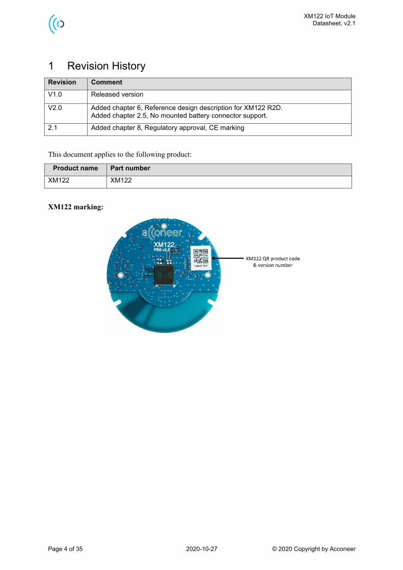
This document applies to the following product:
Product name Part number
XM122 XM122
XM122 marking:

XM122 IoT Module Datasheet, v2.1
Page 5 of 35 2020-10-27 © 2020 Copyright by Acconeer
2 Functional description
2.1 Overview
The XM122 comes with Nordic nRF52840 SoC and A111 Pulsed Coherent Radar (PCR) sensor, see
ref [1]. The Nordic nRF52840 supports Bluetooth 5/Bluetooth Mesh/Thread/Zigbee/
802.15.4/ANT/2.4 GHz.
The XM122 is delivered with a bootloader enabling customer to download Acconeer RSS software
including SDK (Software Development Kit) for stand-alone usage where customer can embed their
own application on top of Acconeer RSS software. Acconeer RSS software provides API to set A111
sensor configuration and to retrieve supported radar services and detector data.
XM122 offers support as well to act as controlled by external host through register command protocol
on UART, SPI and I2C.
2.2 Product features
The XM122 is an IoT module based on Acconeer A111 pulsed coherent radar (PCR) and the Nordic
nRF52840 SoC.
XM122 features:
• The A111 60 GHz Pulsed Coherent radar (PCR) with integrated baseband, RF front-end and
Antenna in Package (AiP).
• Low power connected radar module.
• The nRF52840 protocol stack support for Bluetooth 5, Bluetooth mesh, Thread, Zigbee,
802.15.4, ANT and 2.4 GHz proprietary stacks and is built around the 64 MHz ARM®
Cortex™-M4 CPU with 256 KB SRAM and 1 MB Flash.
• Integrated 2.4 GHz antenna with support for external 2.4 GHz antenna.
• Optional NFC antenna support for quick Bluetooth pairing via the PCB test points.
• Optimized circular form factor with a diameter of 33 mm.
• Wide single supply operating voltage range 2.0 V to 5.5 V.
• Operating temperature -40° to 85°C.
• External I/F support - SPI, UART, I2C, GPIO, Reset.
• SWD/JTAG for SW flash and debug.
The XM122 can be used for accurate distance measurement, tank level measurement, waste bin level
measurement, parking space occupancy and presence detection:
• High precision distance measurements with configurable update frequency.
• Measures absolute range up to 7 m with an absolute accuracy in mm.
• Measures relative accuracy in 42 µm (using RSS software IQ service).
• Possible to recognize movement of multiple objects.
Easy integration:
• XM122 can be integrated behind plastic or glass without any need for a physical aperture. See
ref [6] User guide – Sensor Integration Electromagnetic Scattering for more information.

XM122 IoT Module Datasheet, v2.1
Page 6 of 35 2020-10-27 © 2020 Copyright by Acconeer
2.3 Block diagram
Figure 2.1. XM122 block diagram.
The XM122 block diagram shows the A111 60 GHz PCR radar connected to the nRF52840
microcontroller. The module provides a pin connector where the MCU external I/F are accessible
including single voltage supply.

XM122 IoT Module Datasheet, v2.1
Page 7 of 35 2020-10-27 © 2020 Copyright by Acconeer
2.4 Module board connector and pin description
The board to board connector provides the external interface to the module. Figure 2.2 shows the
connector footprint and Table 2.1 describes each signal.
Figure 2.2. XM122 J2 connector footprint.
Pin Number
Signal Description nRF52840*
pin
1 GPIO P0.23
2 GND Ground -
3 GND Ground -
4 VIN 2.0-5.5 V external power supply. Pin 4 and Pin 6
are interconnected.
-
5 GPIO P0.21
6 VIN 2.0-5.5 V external power supply. Pin 4 and Pin 6
are interconnected.
-
7 GND Ground -
8 GND Ground -
9 GPIO P0.24
10 GPIO Configurable as Analog Input. P0.04
11 GND Ground -
12 GPIO Configurable as JTAG Trace signal. P0.11
TRACEDATA2
13 GPIO P0.22
14 GPIO Configurable as JTAG Trace signal. P0.12
TRACEDATA1
15 GND Ground -
16 VDD Regulated 1.8 V output voltage. -
17 GPIO/UART_RX Default configuration in Acconeer Module server
SW is UART. Could also be used as
miscellaneous GPIO.
P0.06
18 GPIO, nRESET nRF52840 reset pin. P0.18
nRESET
XM122 IoT Module Datasheet, v2.1
Page 8 of 35 2020-10-27 © 2020 Copyright by Acconeer
19 GPIO/UART_TX Default configuration in Acconeer Module server
SW is UART. Could also be used as
miscellaneous GPIO.
P0.16
20 SWDIO SWD interface for flash and debug. SWDIO
21 GND Ground -
22 GPIO, SWO SWD interface for flash and debug. Configurable
as JTAG Trace signal.
P1.00
TRACEDATA0
23 GPIO Configurable as JTAG Trace signal. P0.07
TRACECLK
24 GND Ground -
25 GPIO Configurable as JTAG Trace signal. P1.09
TRACEDATA3
26 SWDCLK SWD interface for flash and debug. SWDCLK
27 GPIO/UART_RTS Default configuration in Acconeer Module server
SW is UART. Could also be used as
miscellaneous GPIO.
P0.20
28 GND Ground -
29 GPIO/UART_CTS Default configuration in Acconeer Module server
SW is UART. Could also be used as
miscellaneous GPIO.
P0.19
30 GPIO, DFU Device Firmware Upgrade. Set low during reset
to enter bootloader mode. Could also be used as
miscellaneous GPIO.
P0.25
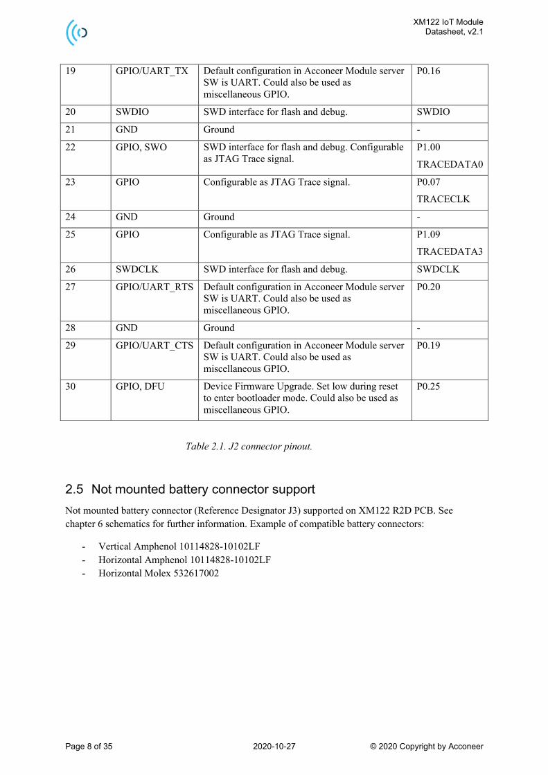
Table 2.1. J2 connector pinout.
2.5 Not mounted battery connector support
Not mounted battery connector (Reference Designator J3) supported on XM122 R2D PCB. See
chapter 6 schematics for further information. Example of compatible battery connectors:
- Vertical Amphenol 10114828-10102LF - Horizontal Amphenol 10114828-10102LF - Horizontal Molex 532617002

XM122 IoT Module Datasheet, v2.1
Page 9 of 35 2020-10-27 © 2020 Copyright by Acconeer
2.6 Software options
The XM122 module can be used in two regimes:
• Stand-alone module: The module operates as an independent system. The application is
customized to a specific use case by the customer and runs on the embedded MCU. The
customers application is accessing the RSS API.
• Controlled module: The module is connected to an external host where the customer runs
their application software. The customers are accessing the RSS API via a hardware interface
through the module server, that provides register command protocol. The module output is
either detector output data or service radar data through the XM122 external interfaces such as
SPI, UART and I2C.
Using the XM122 as stand-alone module Acconeer offers SDK that provides RSS, hardware
abstraction layer, device drivers and build system. Based on SDK it is possible for the customer to
develop their own application. Both RSS and applications runs on the embedded MCU.
Using the XM122 as Controlled module Acconeer provides SW image including RSS and module
server application that provides hardware interface accessing the RSS API through a register
command protocol, see ref [3].
For further software information, see XM122 IoT Module Evaluation Kit User guide, ref [2].
2.7 MAC addresses
The XM122 module comes with a Static Random Bluetooth Address provided by the Nordic
nRF52840 SoC. This address is assigned randomly during manufacturing. This static address can be
used for evaluation.

XM122 IoT Module Datasheet, v2.1
Page 10 of 35 2020-10-27 © 2020 Copyright by Acconeer
3 Interfaces
3.1 Module supply input
The XM122 support external single power supply for battery power applications, see table 4.2
recommended operating conditions.
Note that supply voltage conditions (E.g. slew rate) need to be taken into consideration according to
nRF52840 datasheet, ref [5].
3.2 System functions
The XM122 IoT module supports system power states, see XM122 Module Software User guide, Ref
[3] for further information.
Module RESET is supported by activating NRST pin (active low).
Module ERASE is used to reinitialize the MCU Flash content and some of its NVM (Non-Volatile
Memory) bits to an erased state. See nRF52840 datasheet, ref [5] for further information.
3.3 Serial interfaces
The XM122 nRF52840 GPIO pins can be configured to support up to two UART, up to four SPI
master or three SPI slave and up to two I2C compatible 2-wire master/slave external serial interfaces.
See table 2.1 for HW configuration. See also nRF52840 datasheet, ref [5] for further information.
3.4 Digital I/O interfaces
The XM122 module support General Purpose IOs (GPIOs), 16 GPIOs are available. The GPIO pins
are configurable for different functions, only the debug and RESET pins are fixed to specific GPIOs.
See table 2.1 for HW configuration. See also nRF52840 datasheet, ref [5] for further information.
3.5 Analog I/O interfaces
The XM122 module support one analog input (pin 10 on XM122 connector J2) and up to four
individual PWM outputs which can be assigned to any of the GPIO pins. See table 2.1 for HW
configuration.
3.6 Module reset
The XM122 has an external reset option (Pin 18 on XM122 connector J2) that can be configured as a
GPIO or RESET input.
3.7 Debug interface
The XM122 has 7 debug pins, SWDIO, SWDCLK and Trace signals. TRACE signals reuse GPIO pins.
See table 2.1 for HW configuration.

XM122 IoT Module Datasheet, v2.1
Page 11 of 35 2020-10-27 © 2020 Copyright by Acconeer
4 Electrical specifications
4.1 Absolute maximum ratings
The below table shows the XM122 absolute maximum ratings over operating temperature range,
unless otherwise noted:
Parameter Description Min. Max. Unit
VIN power supply -0.3 6.0 V
I/O Voltage on I/O pins -0.3 2.1 V
TOP Operating temperature range -40 85 °C
TSTG High temperature storage 125 °C
Table 4.1. Absolute maximum ratings.
Stresses beyond those listed in table 5.1 may cause permanent damage to the device. These are stress
ratings only and functional operation of the device at these conditions or at any other conditions
beyond those indicated under Recommended Operating Conditions is not implied. Exposure to
absolute-maximum-rated conditions for extended periods of time may affect device reliability.
4.2 Recommended operating conditions
The below table shows the XM122 recommended operating conditions:
Parameter Min. Typ. Max. Unit
VIN, operating power supply voltage1) 2.0 5.5 V
I/O operating range 0 1.8 V
Operating temperature1) -40 85 ºC
Table 4.2. Recommended operating conditions.
1 Minimum battery voltage depends on battery internal resistance and temperature.

XM122 IoT Module Datasheet, v2.1
Page 12 of 35 2020-10-27 © 2020 Copyright by Acconeer
4.3 Power consumption summary
The below table summarizes the XM122 power consumption, maximum current ratings and average
current ratings at power terminal at TA = 25ºC and 2.0 V/3.0 V supply:
Parameter Min. Typ. Max. Unit
Average power consumption, 2.0 V supply, 0.1 Hz update rate 0.07 (1) mW
Average power consumption, 3.0 V supply, 0.1 Hz update rate 0.08 (1) mW
Average power consumption, 2.0 V supply, 1 Hz update rate 0.66 (1) mW
Average power consumption, 3.0 V supply, 1 Hz update rate 0.67 (1) mW
Average power consumption, 2.0 V supply,10 Hz update rate 6.43 (1) mW
Average power consumption, 3.0 V supply, 10Hz update rate 6.51 (1) mW
Idle current 3.75 (2) µA
Table 4.3. Average power dissipation ratings at power terminal.
1 Measuring window set to 0.6m, configuration with Envelope service, maximize SNR profile used. Bluetooth advertisement
according to given update rate.
2 Sensor is powered off and nRF52840 is in sleep mode (System ON) with full RAM retention and wake-up on RTC enabled.

XM122 IoT Module Datasheet, v2.1
Page 13 of 35 2020-10-27 © 2020 Copyright by Acconeer
4.4 RF specification
The below table shows the XM122 A111 PCR RF specification:
Parameter Min. Typ. Max. Unit
Center frequency fc 60.5 GHz
EIRP (Equivalent Isotropically Radiated Power) 10 dBm
HPBW (Half Power Beam Width), elevation plane 45 degrees
HPBW (Half Power Beam Width), horizontal plane 70 degrees
Table 4.4. XM122 RF specification.
The XM122 support Bluetooth v5 including BLE, mesh, long range and advertising extensions.
The below table shows the XM122 Bluetooth radio performance:
Parameter Min. Typ. Max. Unit
Frequency (40 channels) 2.4 2.48 GHz
Data rate 2 Mbps
Total radiated power (TRP) 5.5 dBm
Conducted RX sensitivity (BLE) -97 dBm
Conducted RX sensitivity (Long range) -101 dBm
Conducted total link budget -109 dBm
Table 4.5. XM122 Bluetooth radio performance.

XM122 IoT Module Datasheet, v2.1
Page 14 of 35 2020-10-27 © 2020 Copyright by Acconeer
5 Reference design description XM122 R2C
5.1 Schematics & BOM
The following pages include the module schematics and bill of materials:

XM122 IoT Module Datasheet, v2.1
Page 15 of 35 2020-10-27 © 2020 Copyright by Acconeer

XM122 IoT Module Datasheet, v2.1
Page 16 of 35 2020-10-27 © 2020 Copyright by Acconeer

XM122 IoT Module Datasheet, v2.1
Page 17 of 35 2020-10-27 © 2020 Copyright by Acconeer

XM122 IoT Module Datasheet, v2.1
Page 18 of 35 2020-10-27 © 2020 Copyright by Acconeer
Bill of Material
Table 5.1 shows the BOM for XM122.
Component Ref. Specification QTY Value Comment
C10 NP0,C0G/1005 1 100 pF
C12, C13, C33, C34 NP0,C0G/1005 4 8 pF
C14 C0G/1005 1 0.75 pF
C15 C0G/1005 1 0.5 pF
C17 X5R/1005 1 4.7 uF
C19 NP0/1005 1 820 pF
C2,C7, C18, C22, C25, C29, C31, C32
X7R/1005 8 100 nF
C23, C24 X5R/1608 2 22 uF
C26 X5R/1005 1 10 uF
C3,C5, C27, C28, C30, C36
X5R/1005 6 1 uF
C4 X5R/1005 1 47 nF
C40 N/A/1005 1 2pF
C8, C9 NP0/1005 2 15 pF
D2 LTST-C190CKT 1 N/A
J1 MM8130-2600 1 N/A
J2 DF40HC(3.5)-30DS-0.4V(51) 1 J2
L1 15/NH/1005/J 1 15 nH
L2 10/UH/1608 1 10 uH
L3 4.7/nH/1005/+-0.3nH 1 4.7 µH
L4 2.2/uH/1608/M 1 2.2 uH Footprint
1608
L5
2.2/UH/2520/M
Murata DFE252012P-2R2M=P2
1 2.2 uH Footprint 2520
R1 1 360 Ohm
R10 1 470 KOhm
R2 1 180 kOhm
R6, R9, R12 3 33 Ohm
R7 1 0.5 Ohm
R8, R13 2 0 Ohm
U1, U4 TPS22916BYFPR 2 N/A Regulator
U2 NORDIC_BT5.0_LONGRANGE 1 N/A MCU/BT

XM122 IoT Module Datasheet, v2.1
Page 19 of 35 2020-10-27 © 2020 Copyright by Acconeer
_NRF5284 module
U3 TPS62840DLCR 1 N/A Regulator
U5 A111 1 N/A PCR
U6 1 N/A BU4818F-**
X1 32MHz/10ppm/10PF/50OH
M/2520 1 32 MHz
X2 32.768kHz/20ppm/9.5PF/90
KOHM/2 1 32.768kHz
X3 TSX-3225 24.0000MF20G-
AC0/SMD(3225Size) 1 24 MHz
Table 5.1. XM122 BOM list.

XM122 IoT Module Datasheet, v2.1
Page 20 of 35 2020-10-27 © 2020 Copyright by Acconeer
5.2 Component Placement Drawing
The component placement drawing of XM122 is found below:
Top side

XM122 IoT Module Datasheet, v2.1
Page 21 of 35 2020-10-27 © 2020 Copyright by Acconeer
Bottom side:
XM122 IoT Module Datasheet, v2.1
Page 22 of 35 2020-10-27 © 2020 Copyright by Acconeer
6 Reference design description XM122 R2D
6.1 Schematics & BOM
The following pages include the module schematics and bill of materials:

XM122 IoT Module Datasheet, v2.1
Page 23 of 35 2020-10-27 © 2020 Copyright by Acconeer

XM122 IoT Module Datasheet, v2.1
Page 24 of 35 2020-10-27 © 2020 Copyright by Acconeer

XM122 IoT Module Datasheet, v2.1
Page 25 of 35 2020-10-27 © 2020 Copyright by Acconeer

XM122 IoT Module Datasheet, v2.1
Page 26 of 35 2020-10-27 © 2020 Copyright by Acconeer
Bill of Material
Table 6.1 shows the BOM for XM122.
Component Ref. Specification QTY Value Comment
C2,C7,C18,C22,C25,C
29,C31,C32
100/NF/K/50V/X7R/1005 8 100 nF
C3,C5,C27,C28,C30,C
36
1/UF/K/10V/X5R/1005 6 1uF
C4 47/NF/K/50V/X5R/1005 1 47nF
C8,C9 15/PF/J/50V/NP0/1005 2 15pF
C10 100/PF/J/10V/NP0,C0G/10
05
1 100pF
C12,C13,C33,C34 8/PF/C/50V/NP0,C0G/1005 4 8pF
C14 0.75/PF/B/50V/C0G/1005 1 0.8pF
C15 0.5/PF/C/50V/C0G/1005 1 0.5pF
C17 4.7/UF/M/10V/X5R/1005 1 4.7uF
C19 820/PF/F/50V/NP0/1005 1 820pF
C23,C24 22/UF/M/10V/X5R/1608 2 22uF
C26 10/UF/M/10V/X5R/1005 1 10uF
C40 2/PF/C/50V/N/A/1005 1 2pF
D2 LTST-C190CKT 1 638nm LED RED CLEAR CHIP
SMD
J1 MM8130-2600 1
J2 DF40HC(3.5)-30DS-0.4V(51) 1 Manufacturer: Hirose
L1 15/NH/1005/J 1 15nH
Manufacturer: Murata
Part number:
LQG15HS15NJ02
L2 10/UH/1608 1 10uH
Manufacturer: TDK
Part number:
MLZ1608N100LT000
L3 4.7/nH/1005/+-0.3nH 1 4.7nH
Manufacturer: TDK
Part number:
MHQ1005P4N7ST000
L4 2.2/uH/1608/M 1 2.2uH
Manufacturer: TDK
Part number:
MLZ1608N2R2LT000

XM122 IoT Module Datasheet, v2.1
Page 27 of 35 2020-10-27 © 2020 Copyright by Acconeer
L5 2.2/UH/2520/M 1 2.2uH
Manufacturer: Murata
Part number:
DFE252012P-2R2M=P2
R1 360/Kohm/J/1005 1 360 kOhm
R2 180/KOHM/F/1005 1 180kOhm
R6, R9, R12 33/OHM/F/1005 3 33 Ohm
R7 0.5/OHM/J/1005 1 0.5 Ohm
R8, R13 0/OHM/J/1005 2 0 Ohm
R10 470/KOHM/F/1005 1 470 kOhm
U1, U4 SIP32431DNP3_T1GE4 2
U2 NORDIC_BT5.0_LONGRANG
E_NRF52840 1 NRF52840_QIAA
U3 TPS62840DLCR 1
U5 A111 R2D 1
U6 BU4818F-TR 1
X1 32MHz/10ppm/10PF/50OH
M/2520 1
X2 32.768kHz/20ppm/9.5PF/9
0KOHM/2 1
X3 TSX-3225 24.0000MF20G-
AC0/SMD 1
Table 6.1. XM122 BOM list.
XM122 IoT Module Datasheet, v2.1
Page 28 of 35 2020-10-27 © 2020 Copyright by Acconeer
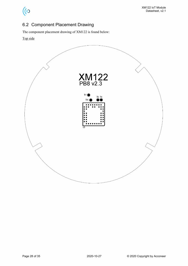
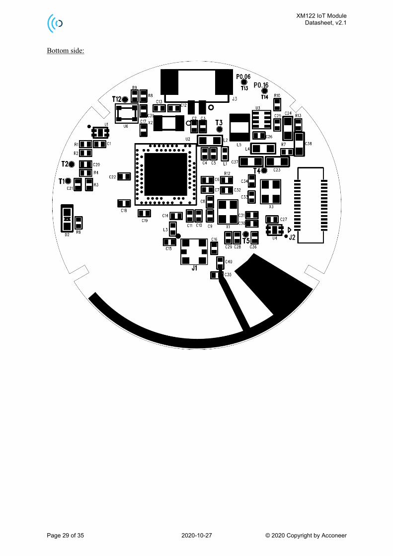
6.2 Component Placement Drawing
The component placement drawing of XM122 is found below:
Top side
XM122 IoT Module Datasheet, v2.1
Page 29 of 35 2020-10-27 © 2020 Copyright by Acconeer
Bottom side:

XM122 IoT Module Datasheet, v2.1
Page 30 of 35 2020-10-27 © 2020 Copyright by Acconeer
7 Mechanical specifications
XM122 Module outline – Top view

XM122 IoT Module Datasheet, v2.1
Page 31 of 35 2020-10-27 © 2020 Copyright by Acconeer
XM122 Module outline – Side view
Distance Value Tolerance
D1 33.0 mm +/-0.2 mm
H1 0.82 mm +/-0.07 mm
H2 0.8 mm +/-0.2 mm
H3 1.4 mm +/-0.1 mm
H4 3.4 mm +/-0.15 mm
G1 1.0 mm +/-0.15 mm
G2 2.0 mm +/-0.15 mm
G3 1.0 mm +/-0.15 mm

XM122 IoT Module Datasheet, v2.1
Page 32 of 35 2020-10-27 © 2020 Copyright by Acconeer
8 Regulatory Approval
To be noted is that some regulatory specifications also specify the usage of the module, so users of the
module must check regulatory requirements for their own use case and determine if the regulatory
approvals described below are sufficient.
8.1 ETSI
Hereby, Acconeer declares that the XM122 module is compliant with directive 2014/53/EU. The
XM122 module fulfills the CE marking.

XM122 IoT Module Datasheet, v2.1
Page 33 of 35 2020-10-27 © 2020 Copyright by Acconeer
9 Reference documents
[1] A111 Pulsed Coherent Radar (PCR) Datasheet:
https://www.acconeer.com/products
[2] XM122 IoT Module Evaluation Kit, User guide
https://www.acconeer.com/products
[3] XM122 Module Software User guide
https://www.acconeer.com/products
[4] XB122 IoT Module Breakout board, Product brief
https://www.acconeer.com/products
[5] Nordic nRF50840:
Nordic Semiconductor
[6] User Guide – Sensor Integration Electromagnetic Scattering
https://www.acconeer.com/products
XM122 IoT Module Datasheet, v2.1
Page 34 of 35 2020-10-27 © 2020 Copyright by Acconeer
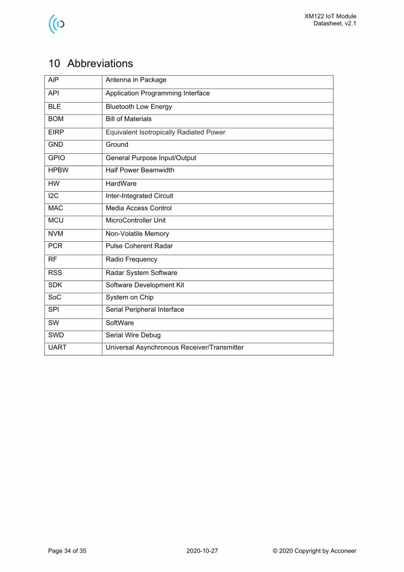
10 Abbreviations
AiP Antenna in Package
API Application Programming Interface
BLE Bluetooth Low Energy
BOM Bill of Materials
EIRP Equivalent Isotropically Radiated Power
GND Ground
GPIO General Purpose Input/Output
HPBW Half Power Beamwidth
HW HardWare
I2C Inter-Integrated Circuit
MAC Media Access Control
MCU MicroController Unit
NVM Non-Volatile Memory
PCR Pulse Coherent Radar
RF Radio Frequency
RSS Radar System Software
SDK Software Development Kit
SoC System on Chip
SPI Serial Peripheral Interface
SW SoftWare
SWD Serial Wire Debug
UART Universal Asynchronous Receiver/Transmitter

XM122 IoT Module Datasheet, v2.1
Page 35 of 35 2020-10-27 © 2020 Copyright by Acconeer
Disclaimer
The information herein is believed to be correct as of the date issued. Acconeer AB (“Acconeer”) will
not be responsible for damages of any nature resulting from the use or reliance upon the information
contained herein. Acconeer makes no warranties, expressed or implied, of merchantability or fitness
for a particular purpose or course of performance or usage of trade. Therefore, it is the user’s
responsibility to thoroughly test the product in their particular application to determine its performance,
efficacy and safety. Users should obtain the latest relevant information before placing orders.
Unless Acconeer has explicitly designated an individual Acconeer product as meeting the requirement
of a particular industry standard, Acconeer is not responsible for any failure to meet such industry
standard requirements.
Unless explicitly stated herein this document Acconeer has not performed any regulatory conformity
test. It is the user’s responsibility to assure that necessary regulatory conditions are met and approvals
have been obtained when using the product. Regardless of whether the product has passed any
conformity test, this document does not constitute any regulatory approval of the user’s product or
application using Acconeer’s product.
Nothing contained herein is to be considered as permission or a recommendation to infringe any
patent or any other intellectual property right. No license, express or implied, to any intellectual
property right is granted by Acconeer herein.
Acconeer reserves the right to at any time correct, change, amend, enhance, modify, and improve this
document and/or Acconeer products without notice.
This document supersedes and replaces all information supplied prior to the publication hereof.
© 2020 by Acconeer – All rights reserved
Acconeer AB www.acconeer.com
IDEON Gateway [email protected]
Scheelevägen 27 +46 10 218 92 00
223 63 LUND
Sweden