xml based schema definition for support of inter ...xml.coverpages.org/aalst-det_01.pdf · 1 xml...
TRANSCRIPT
1
XML Based Schema Definition for Support of Inter-organizational Workflow
W.M.P. van der Aalst1,2 and A. Kumar1
1 College of Business and Administration, University of Colorado,Campus Box 419, Boulder, CO 80309-0419, USA.
2 Faculty of Technology and Management, Eindhoven University of Technology,PO Box 513, NL-5600 MB, Eindhoven, The Netherlands.
E-mail: [email protected],[email protected]
Abstract
Commerce on the Internet is still seriously hindered by the lack of a common language forcollaborative commercial activities. Although XML (Extendible Markup Language) allows tradingpartners to exchange semantic information electronically, it does not provide support for documentrouting. In this paper, we propose the design for an eXchangeable routing language (XRL) usingXML syntax. Since XML is becoming a major international standard, it is understood widely. Therouting schema in XRL can be used to support flexible routing of documents in the Internetenvironment. The formal semantics of XRL are expressed in terms of Petri nets and examples areused to demonstrate how it can be used for implementing inter-organizational electronic commerceapplications.
1. Introduction
Current workflow products are generally intra-organizational and based on centralized architectures.
Therefore, they typically lack scalability and are also not very useful for implementing inter-
organizational applications [1,5,6,7,33]. With the rapid expansion seen in electronic commerce1,
there is a major need for infrastructures and frameworks that can be used to implement inter-
organizational applications. In particular it is essential to provide support for routing of documents
across organizations in a standardized and yet flexible manner to enable open electronic commerce
[16,17,24,31,33,40]. Developing more homogeneous languages for various electronic commerce
activities [21] is one way to facilitate increased productivity and interoperability. Another strategy is
to build autonomous, cooperating agents that can communicate intelligently with one another [32]. In
this paper, we describe an architecture and language called XRL (eXchangeable Routing Language)
that provide support for routing of workflow between trading partners for providing Internet-based
electronic commerce services. The language comprises of routing constructs that can be used as
building blocks to design routing schemas for inter-organizational applications. It is described in
XML syntax because XML parsers are easily available and XML is becoming an international
standard.
1 In 1998, about $ 43 billion worth of business was done over the Web. This volume is projected to
increase to $1.3 Trillion by 2003.
2
Present electronic commerce applications mainly focus on the front side of business documents [31].
EDI based developments such as UN/EDIFACT, XML/EDI, and open EDI concentrate on the
representation of transaction data. In this paper, we focus on the back side of business documents. The
back side of a business document reflects the business process rather than individual transactions or
transaction data. To illustrate the significance of an explicit notion of a business process in the context
of electronic commerce, we use an example taken from [31]. “Consider only a simple postpayment
contract for goods. The buyer assumes that an invoice will be sent after delivery to trigger the
payment obligation. The seller, on the other hand, abides by the practice that payment becomes due
from the time of delivery, and does not send an invoice. Thus, the goods arrive, and the buyer does
not pay, waiting for an invoice. Meanwhile the seller becomes irked, and initiates collection
proceedings. This is an example of the so-called battle of the forms. Each party utilizes standard
documents such as a purchase order, delivery agreement, etc. which contain (typically on the back
side, in small print) the terms and conditions that are their style of doing business.” Supporting
electronic commerce without specifying the “way of doing business” creates many problems. The
only way to avoid such problems is to make inter-organizational workflow explicit. This observation
was the main motivation for developing XRL.
Several electronic commerce applications have been implemented using centralized architectures and
in synchronous mode. In synchronous (or request-reply) mode a transaction is performed
interactively. The biggest problem with a centralized approach is scalability and reliability. The
problem with a synchronous mode operation is that the client and server must establish a connection
between them, and it is not always possible to have a reliable and fast connection either because the
underlying network is unavailable or the server is overloaded. Moreover, synchronous
communication is not very efficient when a large amount of information has to be exchanged. Thus,
there is a need for a framework that provides better support for asynchronous, flow-type commercial
applications. This kind of situation arises frequently in supply chain management [12,13,30]. In such
situations, asynchronous transmission of messages can be more reliable and efficient. For instance, in
many situations it is considerably easier and more efficient for a customer to place large numbers of
orders (for stocks, books, etc.) or make bids in an electronic market (for several products at the same
time) asynchronously. The proposal described in this paper lends itself to both distributed and
asynchronous modes of operation.
A core feature of XRL is that it provides a mechanism to describe processes at an instance level, i.e.,
an XRL routing schema describes the partial ordering of tasks for one specific instance. Traditional
workflow modeling languages describe processes at a class or type level [19,23,29,36]. Workflow
instances, often referred to as cases, typically have a state which is expressed in terms of the class
model. From an efficiency point of view, it is beneficial to split state (i.e., instance level) and process
model (i.e., class level): If there are many instances of the same class, then duplication of routing
information is avoided. However, in the context of inter-organizational workflow such a split is
3
undesirable. It is unrealistic to assume that the different organizations share a common process model.
Moreover, it should be possible to migrate instances (or parts of instances) from one organization to
another without prior agreement on the precise order in which tasks are executed. Since the XRL
routing schema describes the partial ordering of tasks for one specific instance instead of a class:
• the schema can be exchanged more easily,
• the schema can be changed without causing any problems for other instances, and
• the expressive power is increased (workflow modeling languages typically have problems
handling a variable number of parallel or alternative branches).
Note that a few ad-hoc workflow management systems, e.g., InConcert (TIBCO/InConcert Inc.) and
Ensemble (FileNET Corp.), also support workflow process modeling and enactment at an instance
level [3,4]. However, most of today’s commercial workflow systems focus on production workflow
and handle workflows at a class level. Another limitation of these production workflow systems is
that they typically use a centralized enactment service. Therefore, many of the research prototypes
such as MENTOR (University of Saarland at Saarbrucken), METEOR (University of Georgia),
MOBILE (University of Erlangen), Panta Rhei (University of Klagenfurt), and WASA (University of
Muenster) focus on distribution aspects. The MENTOR system is based on state charts which are
partitioned into fragments. These fragments are distributed under the supervision of Tuxedo, a TP
monitor. The METEOR system is entirely based on CORBA to provide a platform independent and
reliable environment. It also supports interoperability mechanisms like SWAP and JFLOW.
Moreover, the METEOR3 model introduces the notion of foreign task vs. native tasks. A foreign task
refers to a task whose realization (implementation) is unknown to workflow designer, whereas the
implementation details are known to the workflow designer for a native task. Another important
feature for electronic commerce are channels (also called sink nodes) that are used to specify
communication or synchronization between two independent workflows. An interesting project
focussing on the application of workflow technology to electronic commerce is the WIDE Project
(http://dis.sema.es/projects/WIDE/). The goal of this project is to enable inter-organizational
workflows across multiple platforms by linking geographically separated applications including
IBM’s MQSeries Workflow, SAP R/3, Opera, and Structware. Unfortunately, the systems/projects
mentioned (i.e., InConcert, Ensemble, MENTOR, METEOR, MOBILE, Panta Rhei, WASA, and
WIDE) use a propriety format which makes it hard to exchange workflow instances between systems
of different vendors. XRL is based on XML and is not shackled by the history or particularities of an
existing system. The DTD (Document Type Definition) of XRL given in Appendix 1 illustrates the
succinct nature of the language.
4
The semantics of XRL are expressed in terms of Petri nets [8,10,15,34]. Such formal semantics allow
for powerful analysis techniques, an efficient and compact implementation, interfaces to many
existing tools, and, last-but-not-least, an unambiguous understanding of XRL.
This paper is organized as follows. Section 2 provides background material related to workflow
support for Electronic Commerce. Section 3 gives an overview of the architecture based on routing
slips. Next, Section 4 describes the various constructs of the XRL routing language. Then, Section 5
shows that XRL can be mapped into Petri nets. Section 6 illustrates the language with real examples.
Finally, Section 7 concludes the paper.
2. Basic Background and Examples
2.1 HTML, DHTML, CGI, XML
The Web has evolved through various stages. It started as a way of accessing distributed information
on the Internet using a GUI interface based on the HTTP protocol and the HTML language. It was a
successor to Gopher, WAIS and Archie, which were also information access and knowledge
discovery tools but were based on text-based interfaces. The next important advancement was to
make the HTML protocol more interactive using the FORMS programming and Dynamic HTML so
that commercial tasks such as buying and selling, filling in surveys, searching databases, etc, could
also be performed. Several architectures for Web commerce have been proposed, e.g. Commerce Net,
etc. [21] and protocols like SSL and SET [18] have been developed to address security issues that
arise on the Web.
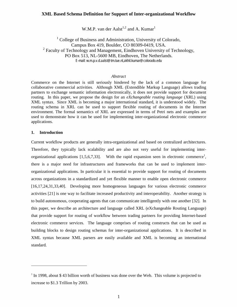
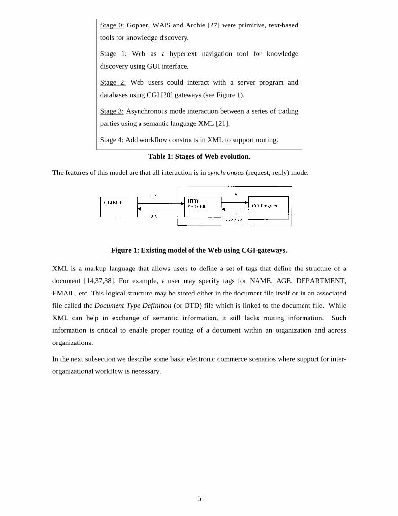
Table 1 summarizes the main stages through which the web has evolved. Stages 2 and 3 reflect the
current stage of development of the web. XML [14,37,38] makes it possible to add semantic
information to an HTML document so that trading partners can understand the meaning of various
fields in the document. Figure 1 shows a common model of how the web operates to provide
interactive services such as shopping, database access, etc. The various steps are as follows:
1,2. A client connects to the server and downloads a form.
3. The client fills in information on the form and submits it.
4,5. A CGI program on the server processes the form.
6. The server sends a reply to the client.
5
Stage 0: Gopher, WAIS and Archie [27] were primitive, text-based
tools for knowledge discovery.
Stage 1: Web as a hypertext navigation tool for knowledge
discovery using GUI interface.
Stage 2: Web users could interact with a server program and
databases using CGI [20] gateways (see Figure 1).
Stage 3: Asynchronous mode interaction between a series of trading
parties using a semantic language XML [21].
Stage 4: Add workflow constructs in XML to support routing.
Table 1: Stages of Web evolution.
The features of this model are that all interaction is in synchronous (request, reply) mode.
Figure 1: Existing model of the Web using CGI-gateways.
XML is a markup language that allows users to define a set of tags that define the structure of a
document [14,37,38]. For example, a user may specify tags for NAME, AGE, DEPARTMENT,
EMAIL, etc. This logical structure may be stored either in the document file itself or in an associated
file called the Document Type Definition (or DTD) file which is linked to the document file. While
XML can help in exchange of semantic information, it still lacks routing information. Such
information is critical to enable proper routing of a document within an organization and across
organizations.
In the next subsection we describe some basic electronic commerce scenarios where support for inter-
organizational workflow is necessary.
6
2.2 Workflow in Mail Order Processing
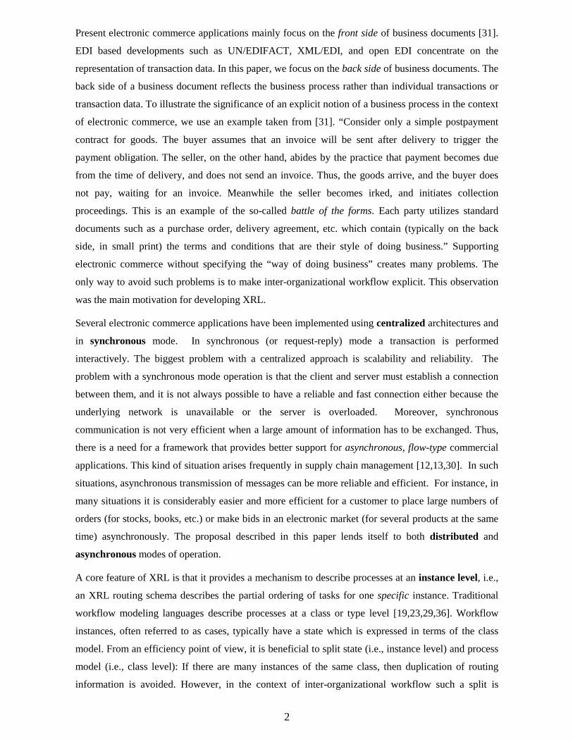
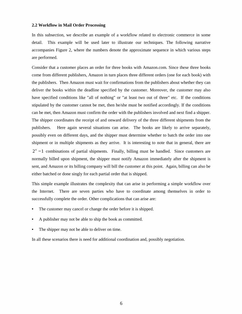
In this subsection, we describe an example of a workflow related to electronic commerce in some
detail. This example will be used later to illustrate our techniques. The following narrative
accompanies Figure 2, where the numbers denote the approximate sequence in which various steps
are performed.
Consider that a customer places an order for three books with Amazon.com. Since these three books
come from different publishers, Amazon in turn places three different orders (one for each book) with
the publishers. Then Amazon must wait for confirmations from the publishers about whether they can
deliver the books within the deadline specified by the customer. Moreover, the customer may also
have specified conditions like "all of nothing" or "at least two out of three" etc. If the conditions
stipulated by the customer cannot be met, then he/she must be notified accordingly. If the conditions
can be met, then Amazon must confirm the order with the publishers involved and next find a shipper.
The shipper coordinates the receipt of and onward delivery of the three different shipments from the
publishers. Here again several situations can arise. The books are likely to arrive separately,
possibly even on different days, and the shipper must determine whether to batch the order into one
shipment or in multiple shipments as they arrive. It is interesting to note that in general, there are
12 −n combinations of partial shipments. Finally, billing must be handled. Since customers are
normally billed upon shipment, the shipper must notify Amazon immediately after the shipment is
sent, and Amazon or its billing company will bill the customer at this point. Again, billing can also be
either batched or done singly for each partial order that is shipped.
This simple example illustrates the complexity that can arise in performing a simple workflow over
the Internet. There are seven parties who have to coordinate among themselves in order to
successfully complete the order. Other complications that can arise are:
• The customer may cancel or change the order before it is shipped.
• A publisher may not be able to ship the book as committed.
• The shipper may not be able to deliver on time.
In all these scenarios there is need for additional coordination and, possibly negotiation.
7
Customer(Joe or Jane)
AmazonBilling Co.
Publisher 1 Publisher 3Publisher2
Shipping Co.
(1)
(8)
(7)
(6)
(5)
(4)(3)(2)
Figure 2: Mail order example.
2.3 Workflow in Health Care
Patient PCP Orthopedist
MCOBank
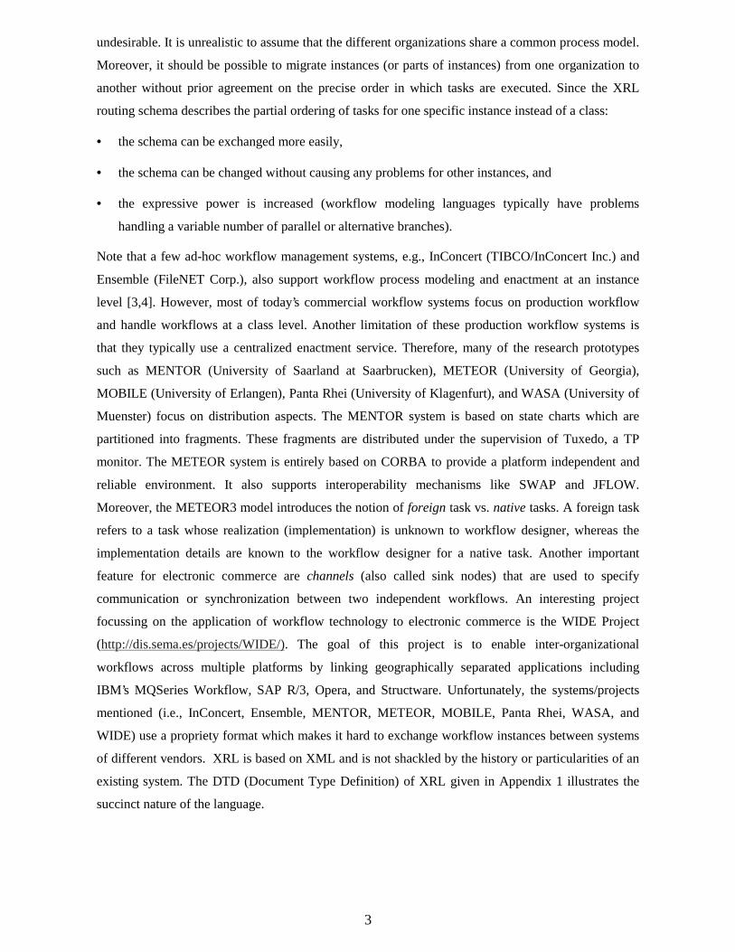
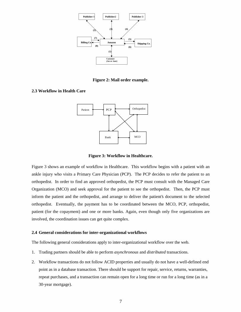
Figure 3: Workflow in Healthcare.
Figure 3 shows an example of workflow in Healthcare. This workflow begins with a patient with an
ankle injury who visits a Primary Care Physician (PCP). The PCP decides to refer the patient to an
orthopedist. In order to find an approved orthopedist, the PCP must consult with the Managed Care
Organization (MCO) and seek approval for the patient to see the orthopedist. Then, the PCP must
inform the patient and the orthopedist, and arrange to deliver the patient’s document to the selected
orthopedist. Eventually, the payment has to be coordinated between the MCO, PCP, orthopedist,
patient (for the copayment) and one or more banks. Again, even though only five organizations are
involved, the coordination issues can get quite complex.
2.4 General considerations for inter-organizational workflows
The following general considerations apply to inter-organizational workflow over the web.
1. Trading partners should be able to perform asynchronous and distributed transactions.
2. Workflow transactions do not follow ACID properties and usually do not have a well-defined end
point as in a database transaction. There should be support for repair, service, returns, warranties,
repeat purchases, and a transaction can remain open for a long time or run for a long time (as in a
30-year mortgage).
8
3. Trading partners should be able to query the status of a workflow at any time.
3. Architecture
We first give a brief discussion of our general approach before developing the architecture. The
approach is based on the notion of a routing slip that defines the routing schema. In the subsequent
discussion the terms routing schema and routing slip are used interchangeably. A routing slip is a
simple sequence of roles or users who must review the documents in a certain sequence. One or more
documents can be attached to, modified and detached from the routing slip by various workers (or
nodes) on the slip. An owner creates the routing slip and defines the routing patterns in terms of
various constructs, to be discussed in the next section. Each slip has a unique ID that can be used to
trace the routing slip.
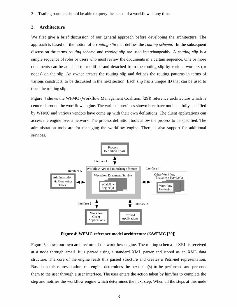
Figure 4 shows the WFMC (Workflow Management Coalition, [29]) reference architecture which is
centered around the workflow engine. The various interfaces shown here have not been fully specified
by WFMC and various vendors have come up with their own definitions. The client applications can
access the engine over a network. The process definition tools allow the process to be specified. The
administration tools are for managing the workflow engine. There is also support for additional
services.
Process Definition Tools
Administration & Monitoring
Tools
Interface 1
Interface 4Interface 5
Workflow Enactment Service
Workflow API and Interchange formats
Other WorkflowEnactment Service(s)
WorkflowClient
Applications
Interface 3Interface 2
WorkflowEngine(s)
WorkflowEngine(s)
InvokedApplications
Figure 4: WFMC reference model architecture (©WFMC [29]).
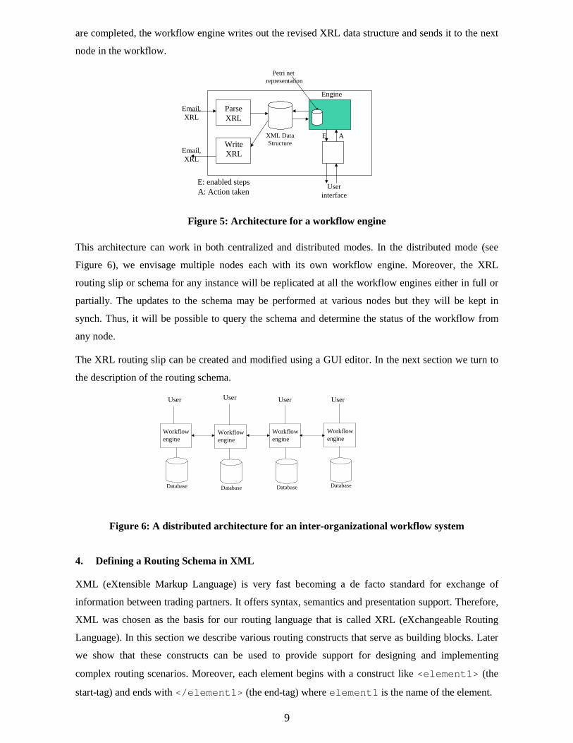
Figure 5 shows our own architecture of the workflow engine. The routing schema in XRL is received
at a node through email. It is parsed using a standard XML parser and stored as an XML data
structure. The core of the engine reads this parsed structure and creates a Petri-net representation.
Based on this representation, the engine determines the next step(s) to be performed and presents
them to the user through a user interface. The user enters the action taken by him/her to complete the
step and notifies the workflow engine which determines the next step. When all the steps at this node
9
are completed, the workflow engine writes out the revised XRL data structure and sends it to the next
node in the workflow.
ParseXRL
Userinterface
WriteXRL
Email,XRL
Email,XRL
XML DataStructure
Engine
Petri net representation
E A
E: enabled stepsA: Action taken
Figure 5: Architecture for a workflow engine
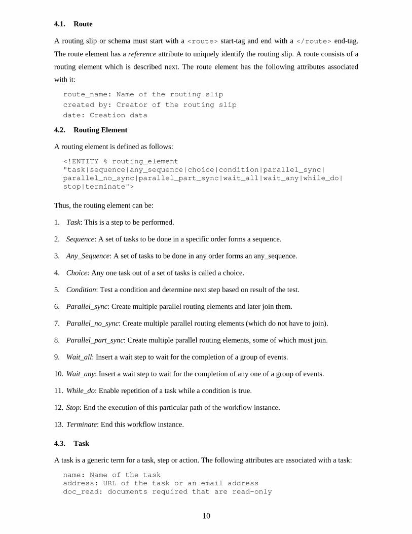
This architecture can work in both centralized and distributed modes. In the distributed mode (see
Figure 6), we envisage multiple nodes each with its own workflow engine. Moreover, the XRL
routing slip or schema for any instance will be replicated at all the workflow engines either in full or
partially. The updates to the schema may be performed at various nodes but they will be kept in
synch. Thus, it will be possible to query the schema and determine the status of the workflow from
any node.
The XRL routing slip can be created and modified using a GUI editor. In the next section we turn to
the description of the routing schema.
Workflowengine
Workflowengine
Workflowengine
Database DatabaseDatabase
Workflowengine
Database
UserUser User User
Figure 6: A distributed architecture for an inter-organizational workflow system
4. Defining a Routing Schema in XML
XML (eXtensible Markup Language) is very fast becoming a de facto standard for exchange of
information between trading partners. It offers syntax, semantics and presentation support. Therefore,
XML was chosen as the basis for our routing language that is called XRL (eXchangeable Routing
Language). In this section we describe various routing constructs that serve as building blocks. Later
we show that these constructs can be used to provide support for designing and implementing
complex routing scenarios. Moreover, each element begins with a construct like <element1> (the
start-tag) and ends with </element1> (the end-tag) where element1 is the name of the element.
10
4.1. Route
A routing slip or schema must start with a <route> start-tag and end with a </route> end-tag.
The route element has a reference attribute to uniquely identify the routing slip. A route consists of a
routing element which is described next. The route element has the following attributes associated
with it:
route_name: Name of the routing slip
created by: Creator of the routing slip
date: Creation data
4.2. Routing Element
A routing element is defined as follows:
<!ENTITY % routing_element "task|sequence|any_sequence|choice|condition|parallel_sync| parallel_no_sync|parallel_part_sync|wait_all|wait_any|while_do| stop|terminate">
Thus, the routing element can be:
1. Task: This is a step to be performed.
2. Sequence: A set of tasks to be done in a specific order forms a sequence.
3. Any_Sequence: A set of tasks to be done in any order forms an any_sequence.
4. Choice: Any one task out of a set of tasks is called a choice.
5. Condition: Test a condition and determine next step based on result of the test.
6. Parallel_sync: Create multiple parallel routing elements and later join them.
7. Parallel_no_sync: Create multiple parallel routing elements (which do not have to join).
8. Parallel_part_sync: Create multiple parallel routing elements, some of which must join.
9. Wait_all: Insert a wait step to wait for the completion of a group of events.
10. Wait_any: Insert a wait step to wait for the completion of any one of a group of events.
11. While_do: Enable repetition of a task while a condition is true.
12. Stop: End the execution of this particular path of the workflow instance.
13. Terminate: End this workflow instance.
4.3. Task
A task is a generic term for a task, step or action. The following attributes are associated with a task:
name: Name of the task address: URL of the task or an email address doc_read: documents required that are read-only
11
doc_update: documents that can be updated doc_create: documents that are to be created domain: Internet domain within which the task is performed result: result of the task as a string value status: status of task (ready|running|enabled|disabled|aborted) start_time: time at which task was started end_time: time at which task was completed notify: Email addresses of parties to be notified on taskcompletion.
A task element must have a unique name attribute which is like an id, and an address that is a URL
(say, an HTML page or ASP or JSP page) or an email address. Several other attributes can be
associated with a task. An example of a task specification is as follows:
<task address="www.order.xyz.com" start_time = "01Oct99;9:30AM", end_time = "">
</task>
A task element may contain events as will be explained later. For tasks without event elements, it
is allowed to combine the start-tag and the end-tag:
<task address="www.order.xyz.com" start_time = "01Oct99;9:30AM", end_time = ""/>
The status attribute is initially null and can take one of the values from among the ones listed above.
The start_time and end_time attributes correspond to the start and end times of the task and
can be used to determine how long it lasts. Another example of a task element is:
<task address = "[email protected]" result = " " doc_read ="doc1, doc2" start_time = "01Oct99;9:30AM", end_time = "">
</task>
Here the address is an email address. Moreover, it is possible to specify documents to be attached
using the attach attribute. Thus, the workflow engine will send an email to the [email protected]
and attach doc1 and doc2 to it.
4.4. Sequence
A sequence represents the simplest routing pattern. It is a way to group together multiple steps into
one group. Here is an example of how a sequential route can be specified using XRL.
<sequence> <task name = "task1" address = "[email protected]" doc_read = "doc1,doc2" > </task> <task name = "task2" address = "[email protected]" doc_read = "doc3,doc4" > </task> <task name = "task3" address = "[email protected]" doc_read = "doc5,doc6" > </task>
12
<task name = "task4" address = "[email protected]" > </task>
</sequence>
In this example several steps are grouped together within the <sequence> element. Thus, a
sequence is a logical way of grouping several sequential tasks.
4.5. Parallel Constructs
There are three types of parallel constructs, which are related: parallel_sync, parallel,
no_sync and parallel_partial_sync.
In all these constructs, the common aspect is that they allow sub-workflows to be created which can
proceed independently. The parallel_sync element corresponds to the traditional notion of
parallel routing: First a number of parallel branches is activated (i.e., the so-called AND-split), then
the parallel branches are executed independently, and finally the completed branches are synchronized
(i.e., the so-called AND-join). In a parallel_sync element, the sub-workflows must combine
together at the end of the element. Finally, in the parallel_part_sync only some of the sub-
workflows need to be combined, as specified in the attribute number.
Next we discuss some examples of these three constructs. In the first example below, three vice-
presidents must approve an invoice before it can be paid. The approvals can be done in parallel, but
subsequent steps of the workflow cannot proceed without receiving the approvals.
<parallel_sync> <task name = "vp1" address = "[email protected]" doc_read = "invoice.doc"/> <task name = "vp2" address = "[email protected]" doc_read = "invoice.doc"/> <task name = "vp3" address = "[email protected]" doc_read = "invoice.doc"/> </parallel_sync>
Next, we consider a modified situation where all the tasks do not need to synchronize. In this case we
would express the requirements as follows using the parallel_part_sync construct.
<parallel_part_sync number = 2> <sequence> <task name = "send-to-vp1" address = "[email protected]" doc_read = "invoice.doc"/> <task name = "vp1" address = "[email protected]" doc_update = "invoice.doc"/> </sequence> <sequence> <task name = "send-to-vp2" address = "[email protected]" doc_read = "invoice.doc"/> <task name = "vp2" address = "[email protected]" doc_update = "invoice.doc"/> </sequence> <sequence>
13
<task name = "send-to-vp3" address = "[email protected]" doc_read = "invoice.doc"/>
<task name = "vp3" address = "[email protected]" doc_update = "invoice.doc"/> </sequence></parallel_part_sync>
In the modified description now, only two of three vice-presidents (any two) are required to approve
the invoice. As soon as any two of them have done so, the workflow may proceed to the next stage.
To show the nesting of constructs, the approval tasks vp1, vp2, and vp3 are proceeded by send tasks
send-to-vp1, send-to-vp2, and send-to-vp3. Note that although the workflow may
proceed to the next stage after two approvals, the third approval may be executed, i.e., the remaining
approval task is not withdrawn explicitly.
Finally, the third option (parallel_no_sync) for parallelism in the workflow design is to not
require any synchronization at all. This would effectively mean that as soon as the three approval
tasks are assigned, the workflow may continue to other tasks. In this case some other mechanism may
be employed to check later that the approvals have indeed been done. For instance, while the
approvals are in progress, other tasks such as printing the check may be performed. However, the
mailing of the check can be delayed until the approvals are obtained. Therefore this semantics would
be expressed in the following way.
<sequence> <parallel_no_sync > <task name = "vp1" address = "[email protected]" doc_update = "invoice.doc"/> <task name = "vp2" address = "[email protected]" doc_update = "invoice.doc"/ > <task name = "vp3" address = "[email protected]" doc_update = "invoice.doc" /> </parallel_no_sync> <parallel> <task name = "check1" address = "check_printing.asp" doc_read = "invoice.doc"/> <task name = "label1" address = "label_printing.asp" doc_read = "invoice.doc"/> </parallel> <parallel_part_sync number = 2> <while_do condition = "vp1.result = ‘Null’ "> <wait_all> <timeout time = "1 minute" type = "relative"/> </wait_all> <while_do/> <while_do condition = "vp2.result = ‘Null’ "> <wait_all> <timeout time = "1 minute" type = "relative"/> </wait_all> <while_do/> <while_do condition = "vp3.result = ‘Null’ " > <wait_all> <timeout time = "1 minute" type = "relative"/>
14
</wait_all> <while_do/> </parallel_part_sync> <task name = "mail_check" address = "mailroom.xyz.com"/></sequence>
In the above XML description, the approval requests are first sent in parallel to the three vice-
presidents. Next, the check printing and label printing tasks are performed. After these tasks are
completed, the parallel_part_sync element is introduced to check how many approvals have
been received. As soon as two approvals are received, the check can be mailed which is the last task.
This example illustrates how all three types of parallel constructs can be combined together. The
while_do construct was used in this example to check if a condition was satisfied. These two
constructs will be explained in more detail in a subsequent subsection.
4.6. Wait, Events, Timeouts.
Next we turn to discuss wait and event elements. There are two types of wait elements: wait_any
and wait_all. Each element encloses one or more combinations of event references and timeouts.
A wait_any element will be considered complete when any one of the events or timeouts it contains
is done. On the other hand, wait_all requires the completion of all of the events or one of the
timeouts it encloses.
An event can be optionally associated with a task by including one or more event elements within a
task element. It is possible to wait for the occurrence of this event within a wait element by specifying
an event reference element. For example,
<task name = approve> <event name = e1 /> </task>
This construct specifies an approve task and associates an event e1 with it such that upon completion
of the task, event e1 will fire. Now, consider the following XML code, which, perhaps, appears later
in the same workflow instance:
<wait_all> <event_ref name = e1/> </wait_all>
This is a way to specify that the workflow instance must wait until the approve task is completed.
Another way to use the wait constructs is in conjunction with timers. There is a timeout element with
attributes time and type. The time attribute specifies a string value of time, while the type
attribute helps to interpret the string value either as an absolute time (January 25, 9 AM),
relative time to the current time (i.e., like a regular timer) or s_relative, i.e., a time which
is relative to the start of the instance. For example,
<wait_all>
15
<timeout time = "1 hour" type = "relative"/> </wait_all>
The event_ref and timeout elements can be combined within a wait_all or wait_any construct
as follow:
<wait_any> <event_ref name = e1/> <timeout time = "1 hour" type = "relative"/> </wait_any>
The semantics here is that any one of these two events must occur for the workflow to move further,
either event e1 should occur or 1 hour should elapse from the start of the wait_any element. This
kind of construction can be very useful for monitoring progress of tasks in the workflow. In the above
case, if the approve task is not done within one hour, the next task can be used to specify an action,
such as sending a reminder to the worker involved or to the responsible manager.
4.7. Condition checking and Looping
The condition element is used to check a general condition statement and direct the workflow based
on a Boolean result. The condition element has an attribute called condition that describes the
condition to be tested. The structure is as follows:
<condition condition = "result = ‘ok’"> <true> <task name = "send_confirmation" address="www.xyz.com/confirm"/> </true> <false> <task name = "notify_customer" address="www.xyz.com/notify"/> </false> </condition>
As shown above the true and false elements are associated in conjunction with the condition
element, and at least one of them should be present.
The while_do construct is introduced to allow repetition of workflow routing elements and steps. It
has a condition attribute that describes the condition (in the same way as with the condition
element), and the elements enclosed within the while_do construct are executed until the condition
evaluates to true. Here is a snippet that appeared in an earlier example:
<while_do condition = "vp3.result = ‘Null’ "> <wait_all> <timeout time = "1 minute" type = relative/> </wait_all> </while_do>
16
In this example, the condition to be tested is the value of vp3.result attribute. Since vp3 is a task
name and result is an attribute associated with a task, we can check its value and make a decision
based on that. The routing element inside the while_do is a wait_all element. This causes a wait
of 1 minute to occur every time before the vp3.result value is checked.
4.8. Terminate, Stop and State Elements
The stop element is used to end a sub-workflow of the workflow instance. The terminate
element on the other hand terminates the entire instance that includes all its paths that may be
executing separately. Both stop and terminate do not have any attributes and are typically used
within a condition element. For example, if a condition in one of several parallel branches
evaluates to false, the entire workflow instance is terminated. The following fragment shows such a
construct in one of the parallel branches:
<condition condition = "result = ‘ok’"> <true> <task name = "transfer_money" address="www.bank.com/transfer"/> </true> <false> <terminate/> </false> </condition>
The state element is required to write out the state of the workflow at any point. This is a useful
feature to make a record of the exact state of the workflow instance in the XRL routing slip. The
location of the state element determines the progress of one thread of the workflow instance. In a
purely sequential process there will be only one state element. In case of parallelism there can be
multiple state elements, each indicating the state of one parallel branch (i.e., one thread). To avoid
confusion, state elements are only allowed inside sequence elements. This is not a limitation
since can routing construct can be embedded in a sequence containing just one routing element.
Consider for example the approval process again:
<parallel_sync> <sequence> <task name = "vp1" address = "[email protected]" doc_read = "invoice.doc"/> <state/> </sequence> <sequence> <state/> <task name = "vp2" address = "[email protected]" doc_read = "invoice.doc"/> </sequence> <sequence> <task name = "vp3" address = "[email protected]" doc_read = "invoice.doc"/>
17
<state/> </sequence> </parallel_sync>
The three approval tasks have been embedded in a sequence construct in order to add the state
elements. The state elements following tasks vp1 and vp3 indicate that these tasks have been
completed. The state element before the task vp2 indicates that task vp2 is enabled but has not
been executed yet. The state following the completion of vp2 can be represented as follows:
<sequence> <parallel_sync> <task name = "vp1" address = "[email protected]" doc_read = "invoice.doc"/> <task name = "vp2" address = "[email protected]" doc_read = "invoice.doc"/> <task name = "vp3" address = "[email protected]" doc_read = "invoice.doc"/> </parallel_sync> <state/> </sequence>
For the explicit representation of the state of a workflow instance, it is also necessary to record the
events that have occurred. Therefore, the state element may contain event elements.
4.9. Formal DTD
A Document Type Definition (DTD) which describes all the constructs is given in Appendix 1 using
standard XML notation [14,37]. The DTD contains markup declarations for the class of XRL
documents. The document element, also called the root, is the route element. Any XRL document
should be well-formed, i.e., taken as a whole it should match the production labeled document in the
XML version 1.0 standard [14]. Moreover, any XRL document should also be valid, i.e., the
document should satisfy the constraints expressed by the declarations in the DTD.
5. Formal Semantics
In Section 4, we introduced the XRL (eXchangeable Routing Language). The syntax of this language
was defined in terms of a DTD. XRL is used to describe the dynamics of inter-organizational
workflows. Therefore, it is of the utmost importance to have clear semantics for each of the constructs
supported by XRL. For this purpose, we map XRL onto Petri nets [34]. On the one hand, Petri nets
can be used to represent the business logic in a graphical manner. In fact, the Petri net language is
close to many of the diagramming languages used by both commercial workflow management
systems and researchers active in this domain [8,10,15]. For example, workflow management systems
and ERP systems such as COSA (Software Ley), Income (Promatis), BaanERP (Baan), and
ARIS/SAP (IDL/SAP) use (variants of) Petri nets. On the other hand, Petri nets are a formal language
with clear semantics, powerful analysis techniques, and strong theoretical results. By mapping XRL
18
onto Petri nets, we give formal semantics, are able to reason about XRL (e.g., about its expressive
power), can use state-of-the-art analysis techniques, and can use existing software. Before we show
the mapping of XRL onto Petri nets, we introduce some of the basic concepts of Petri nets. For a more
elaborate introduction to Petri nets and the application of Petri nets to workflow management, we
refer to [8,10,15,23,34] for further pointers. For more information on the application of Petri nets to
inter-organizational workflows we refer to [1,5,6,7, 31,36]. Petri nets and also other diagramming
techniques used in existing workflow management systems are often too rigid to support business
processes which require flexibility. This is a direct result of the fact that the workflow model is
prescriptive for all possible instances (workflow cases). Note that one of the powerful features of
XRL is the fact that it is used to describe the routing of a single instance, i.e., the model can be
changed on the fly for one particular workflow case. Therefore, the mapping of XRL onto Petri nets
refers to one single case in a given state. If the XRL routing schema is changed, then the
corresponding Petri net is also changed. Hence the Petri net formalism does not restrict the flexibility
of XRL. For more discussion on flexibility issues we refer to [2,3,4].
5.1. Petri Nets
A Petri net is represented graphically by squares and circles. The squares are called transitions and in
the context of workflow management are tasks to be executed. The circles are used to represent the
state of a workflow and are called places. The arrows between places and transitions are used to
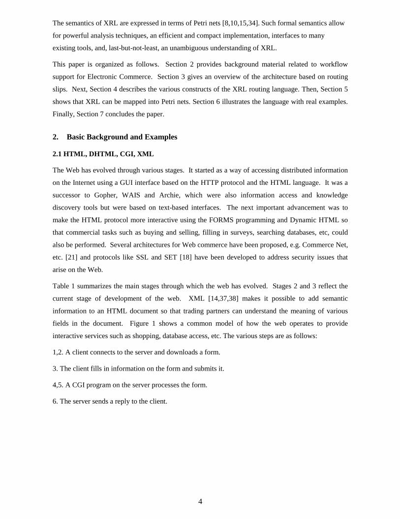
specify causal relations. Figure 7 shows a Petri net composed of six places and six transitions. A place
p is called an input place of a transition t iff there exists a directed arc from p to t. Place p is called an
output place of transition t iff there exists a directed arc from t to p. At any time a place contains zero
or more tokens, drawn as black dots. The state of the net, often referred to as marking, is the
distribution of tokens over places. In Figure 7, only place p1 contains a token. The number of tokens
may change during the execution of the net. Transitions are the active components in a Petri net: They
change the state of the net (also called marking) according to the following firing rule:
• A transition t is said to be enabled iff each input place p of t contains at least one token.
• An enabled transition may fire. If transition t fires, then t consumes one token from each input
place p of t and produces one token for each output place p of t.
19
serve_donut
accept_order
serve_coffee
serve_tea
order_donut
handle_paymentp1
p2
p3 p5
p4
p6
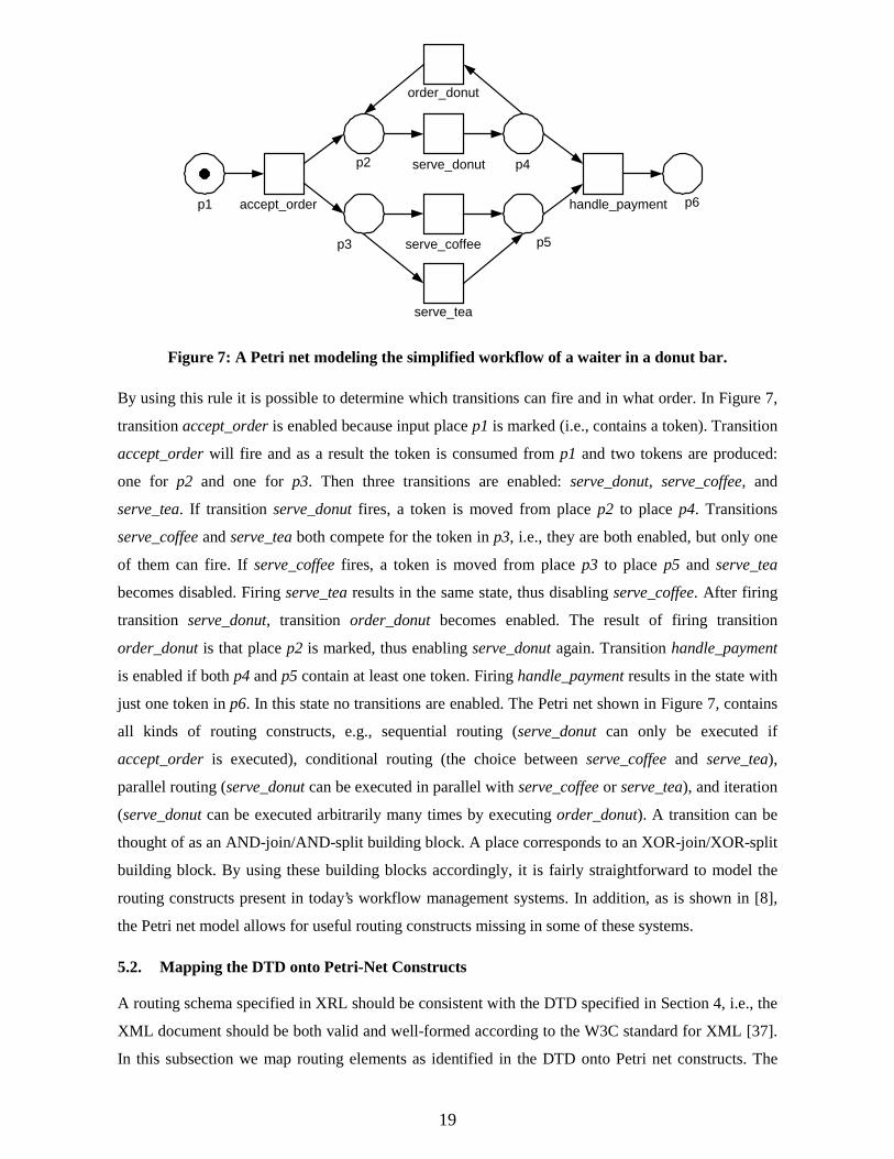
Figure 7: A Petri net modeling the simplified workflow of a waiter in a donut bar.
By using this rule it is possible to determine which transitions can fire and in what order. In Figure 7,
transition accept_order is enabled because input place p1 is marked (i.e., contains a token). Transition
accept_order will fire and as a result the token is consumed from p1 and two tokens are produced:
one for p2 and one for p3. Then three transitions are enabled: serve_donut, serve_coffee, and
serve_tea. If transition serve_donut fires, a token is moved from place p2 to place p4. Transitions
serve_coffee and serve_tea both compete for the token in p3, i.e., they are both enabled, but only one
of them can fire. If serve_coffee fires, a token is moved from place p3 to place p5 and serve_tea
becomes disabled. Firing serve_tea results in the same state, thus disabling serve_coffee. After firing
transition serve_donut, transition order_donut becomes enabled. The result of firing transition
order_donut is that place p2 is marked, thus enabling serve_donut again. Transition handle_payment
is enabled if both p4 and p5 contain at least one token. Firing handle_payment results in the state with
just one token in p6. In this state no transitions are enabled. The Petri net shown in Figure 7, contains
all kinds of routing constructs, e.g., sequential routing (serve_donut can only be executed if
accept_order is executed), conditional routing (the choice between serve_coffee and serve_tea),
parallel routing (serve_donut can be executed in parallel with serve_coffee or serve_tea), and iteration
(serve_donut can be executed arbitrarily many times by executing order_donut). A transition can be
thought of as an AND-join/AND-split building block. A place corresponds to an XOR-join/XOR-split
building block. By using these building blocks accordingly, it is fairly straightforward to model the
routing constructs present in today’s workflow management systems. In addition, as is shown in [8],
the Petri net model allows for useful routing constructs missing in some of these systems.
5.2. Mapping the DTD onto Petri-Net Constructs
A routing schema specified in XRL should be consistent with the DTD specified in Section 4, i.e., the
XML document should be both valid and well-formed according to the W3C standard for XML [37].
In this subsection we map routing elements as identified in the DTD onto Petri net constructs. The
20
root element of a routing schema is of type route. An element of type route contains one routing
element. As was explained in the previous section, there are different types of routing elements
ranging from a simple task to complex routing constructs.
<!ENTITY % routing_element
"task|sequence|any_sequence|choice|condition|parallel_sync|parallel_
no_sync|parallel_part_sync|wait_all|wait_any|while_do|stop|terminate
">
<!ELEMENT route (%routing_element;)>
<!ATTLIST route name ID #REQUIRED
created_by CDATA #IMPLIED
date CDATA #IMPLIED>
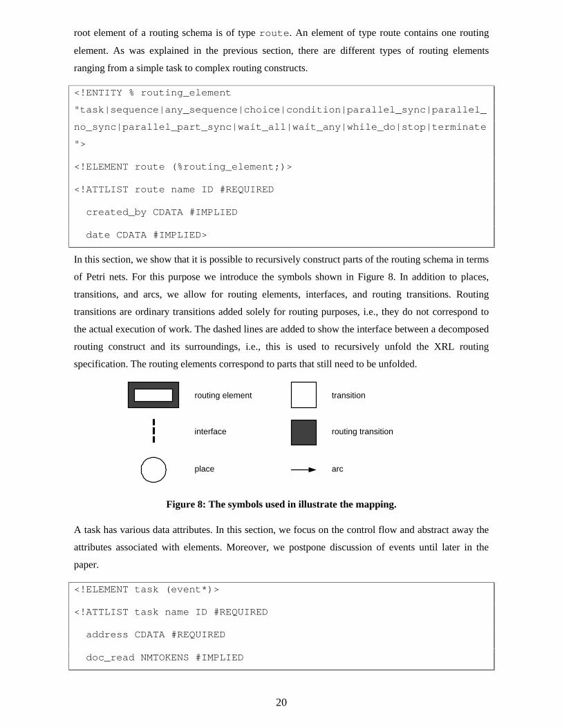
In this section, we show that it is possible to recursively construct parts of the routing schema in terms
of Petri nets. For this purpose we introduce the symbols shown in Figure 8. In addition to places,
transitions, and arcs, we allow for routing elements, interfaces, and routing transitions. Routing
transitions are ordinary transitions added solely for routing purposes, i.e., they do not correspond to
the actual execution of work. The dashed lines are added to show the interface between a decomposed
routing construct and its surroundings, i.e., this is used to recursively unfold the XRL routing
specification. The routing elements correspond to parts that still need to be unfolded.
routing element
interface
place
transition
routing transition
arc
Figure 8: The symbols used in illustrate the mapping.
A task has various data attributes. In this section, we focus on the control flow and abstract away the
attributes associated with elements. Moreover, we postpone discussion of events until later in the
paper.
<!ELEMENT task (event*)>
<!ATTLIST task name ID #REQUIRED
address CDATA #REQUIRED
doc_read NMTOKENS #IMPLIED
21
doc_update NMTOKENS #IMPLIED
doc_create NMTOKENS #IMPLIED
result CDATA #IMPLIED
status (ready|running|enabled|disabled|aborted) #IMPLIED
start_time NMTOKEN #IMPLIED
end_time NMTOKEN #IMPLIED
notify CDATA #IMPLIED>
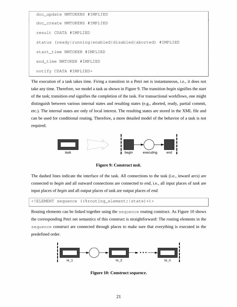
The execution of a task takes time. Firing a transition in a Petri net is instantaneous, i.e., it does not
take any time. Therefore, we model a task as shown in Figure 9. The transition begin signifies the start
of the task; transition end signifies the completion of the task. For transactional workflows, one might
distinguish between various internal states and resulting states (e.g., aborted, ready, partial commit,
etc.). The internal states are only of local interest. The resulting states are stored in the XML file and
can be used for conditional routing. Therefore, a more detailed model of the behavior of a task is not
required.
begin endexecutingtask
Figure 9: Construct task.
The dashed lines indicate the interface of the task. All connections to the task (i.e., inward arcs) are
connected to begin and all outward connections are connected to end, i.e., all input places of task are
input places of begin and all output places of task are output places of end.
<!ELEMENT sequence ((%routing_element;|state)+)>
Routing elements can be linked together using the sequence routing construct. As Figure 10 shows
the corresponding Petri net semantics of this construct is straightforward: The routing elements in the
sequence construct are connected through places to make sure that everything is executed in the
predefined order.
re_1 re_2 re_n
...
Figure 10: Construct sequence.
22
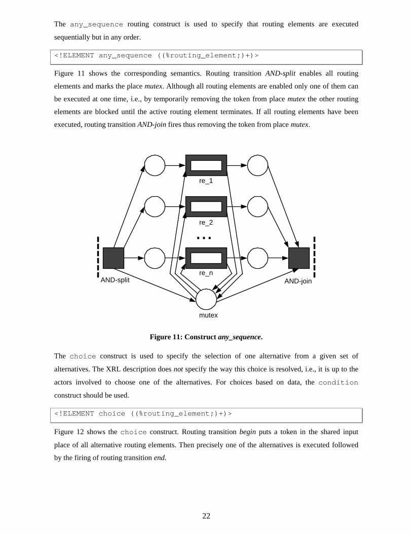
The any_sequence routing construct is used to specify that routing elements are executed
sequentially but in any order.
<!ELEMENT any_sequence ((%routing_element;)+)>
Figure 11 shows the corresponding semantics. Routing transition AND-split enables all routing
elements and marks the place mutex. Although all routing elements are enabled only one of them can
be executed at one time, i.e., by temporarily removing the token from place mutex the other routing
elements are blocked until the active routing element terminates. If all routing elements have been
executed, routing transition AND-join fires thus removing the token from place mutex.
re_n
re_2
re_1
...
mutex
AND-split AND-join
Figure 11: Construct any_sequence.
The choice construct is used to specify the selection of one alternative from a given set of
alternatives. The XRL description does not specify the way this choice is resolved, i.e., it is up to the
actors involved to choose one of the alternatives. For choices based on data, the condition
construct should be used.
<!ELEMENT choice ((%routing_element;)+)>
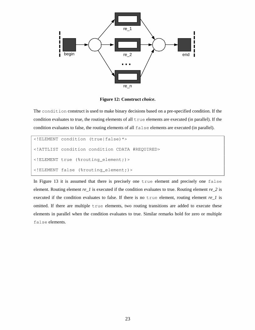
Figure 12 shows the choice construct. Routing transition begin puts a token in the shared input
place of all alternative routing elements. Then precisely one of the alternatives is executed followed
by the firing of routing transition end.
23
re_n
re_2
re_1
...begin end
Figure 12: Construct choice.
The condition construct is used to make binary decisions based on a pre-specified condition. If the
condition evaluates to true, the routing elements of all true elements are executed (in parallel). If the
condition evaluates to false, the routing elements of all false elements are executed (in parallel).
<!ELEMENT condition (true|false)*>
<!ATTLIST condition condition CDATA #REQUIRED>
<!ELEMENT true (%routing_element;)>
<!ELEMENT false (%routing_element;)>
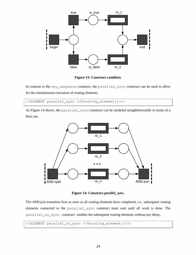
In Figure 13 it is assumed that there is precisely one true element and precisely one false
element. Routing element re_1 is executed if the condition evaluates to true. Routing element re_2 is
executed if the condition evaluates to false. If there is no true element, routing element re_1 is
omitted. If there are multiple true elements, two routing transitions are added to execute these
elements in parallel when the condition evaluates to true. Similar remarks hold for zero or multiple
false elements.
24
false re_2
re_1true is_true
is_false
begin end
Figure 13: Construct condition.
In contrast to the any_sequence construct, the parallel_sync construct can be used to allow
for the simultaneous execution of routing elements.
<!ELEMENT parallel_sync ((%routing_element;)+)>
As Figure 14 shows, the parallel_sync construct can be modeled straightforwardly in terms of a
Petri net.
re_n
re_2
re_1
...
AND-split AND-join
Figure 14: Construct parallel_sync.
The AND-join transition fires as soon as all routing elements have completed, i.e., subsequent routing
elements connected to the parallel_sync construct must wait until all work is done. The
parallel_no_sync construct enables the subsequent routing elements without any delay.
<!ELEMENT parallel_no_sync ((%routing_element;)+)>
25
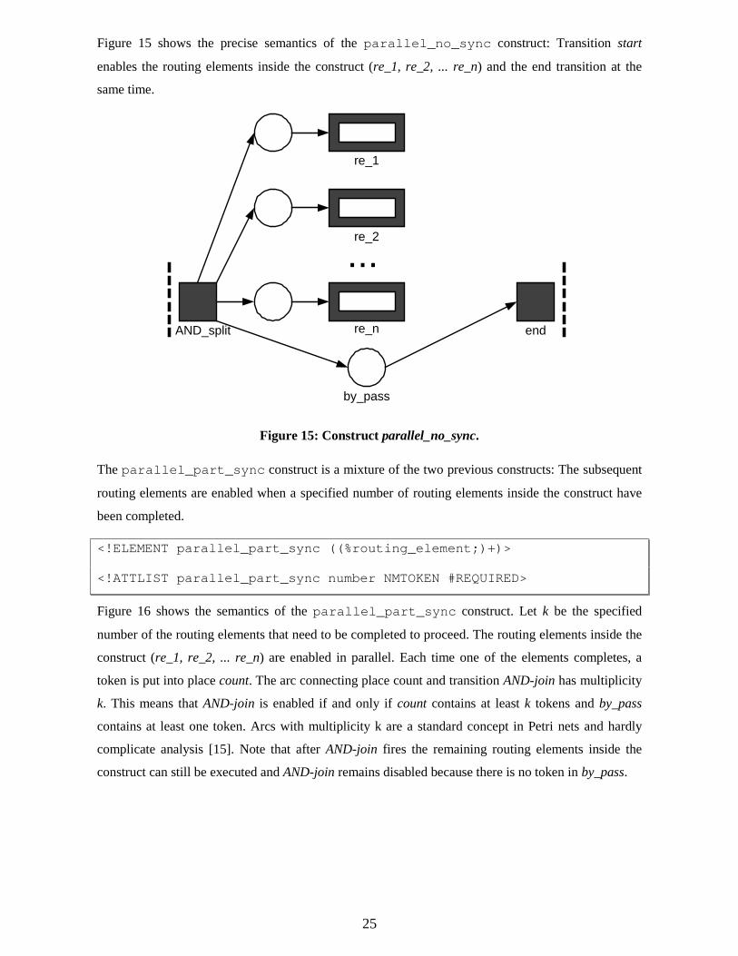
Figure 15 shows the precise semantics of the parallel_no_sync construct: Transition start
enables the routing elements inside the construct (re_1, re_2, ... re_n) and the end transition at the
same time.
re_n
re_2
re_1
...
by_pass
AND_split end
Figure 15: Construct parallel_no_sync.
The parallel_part_sync construct is a mixture of the two previous constructs: The subsequent
routing elements are enabled when a specified number of routing elements inside the construct have
been completed.
<!ELEMENT parallel_part_sync ((%routing_element;)+)>
<!ATTLIST parallel_part_sync number NMTOKEN #REQUIRED>
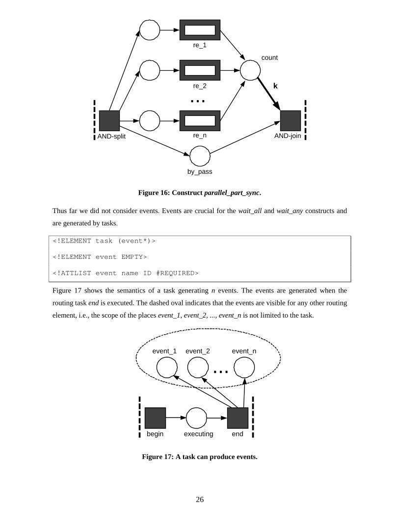
Figure 16 shows the semantics of the parallel_part_sync construct. Let k be the specified
number of the routing elements that need to be completed to proceed. The routing elements inside the
construct (re_1, re_2, ... re_n) are enabled in parallel. Each time one of the elements completes, a
token is put into place count. The arc connecting place count and transition AND-join has multiplicity
k. This means that AND-join is enabled if and only if count contains at least k tokens and by_pass
contains at least one token. Arcs with multiplicity k are a standard concept in Petri nets and hardly
complicate analysis [15]. Note that after AND-join fires the remaining routing elements inside the
construct can still be executed and AND-join remains disabled because there is no token in by_pass.
26
re_n
re_2
re_1
...
AND-split AND-join
k
by_pass
count
Figure 16: Construct parallel_part_sync.
Thus far we did not consider events. Events are crucial for the wait_all and wait_any constructs and
are generated by tasks.
<!ELEMENT task (event*)>
<!ELEMENT event EMPTY>
<!ATTLIST event name ID #REQUIRED>
Figure 17 shows the semantics of a task generating n events. The events are generated when the
routing task end is executed. The dashed oval indicates that the events are visible for any other routing
element, i.e., the scope of the places event_1, event_2, ..., event_n is not limited to the task.
begin endexecuting
...event_1 event_2 event_n
Figure 17: A task can produce events.
27
The wait_all construct waits for certain events that must occur before any subsequent routing
elements. The wait_all construct can terminate in two ways: (1) after all specified events have
occurred, or (2) when a timeout occurs. The wait_all construct may contain multiple timeout
elements: The wait_all construct terminates when the first timeout occurs. In the absence of any
timeout elements, the only way wait_all can terminate is after all events have occurred. As
explained in the previous section, a timeout element has a type attribute with values of absolute,
relative or s_relative.
<!ELEMENT wait_all (event_ref|timeout)+>
<!ELEMENT event_ref EMPTY>
<!ATTLIST event_ref name IDREF #REQUIRED>
<!ELEMENT timeout (%routing_element;)>
<!ATTLIST timeout time CDATA #REQUIRED
type (relative|s_relative|absolute) "absolute">
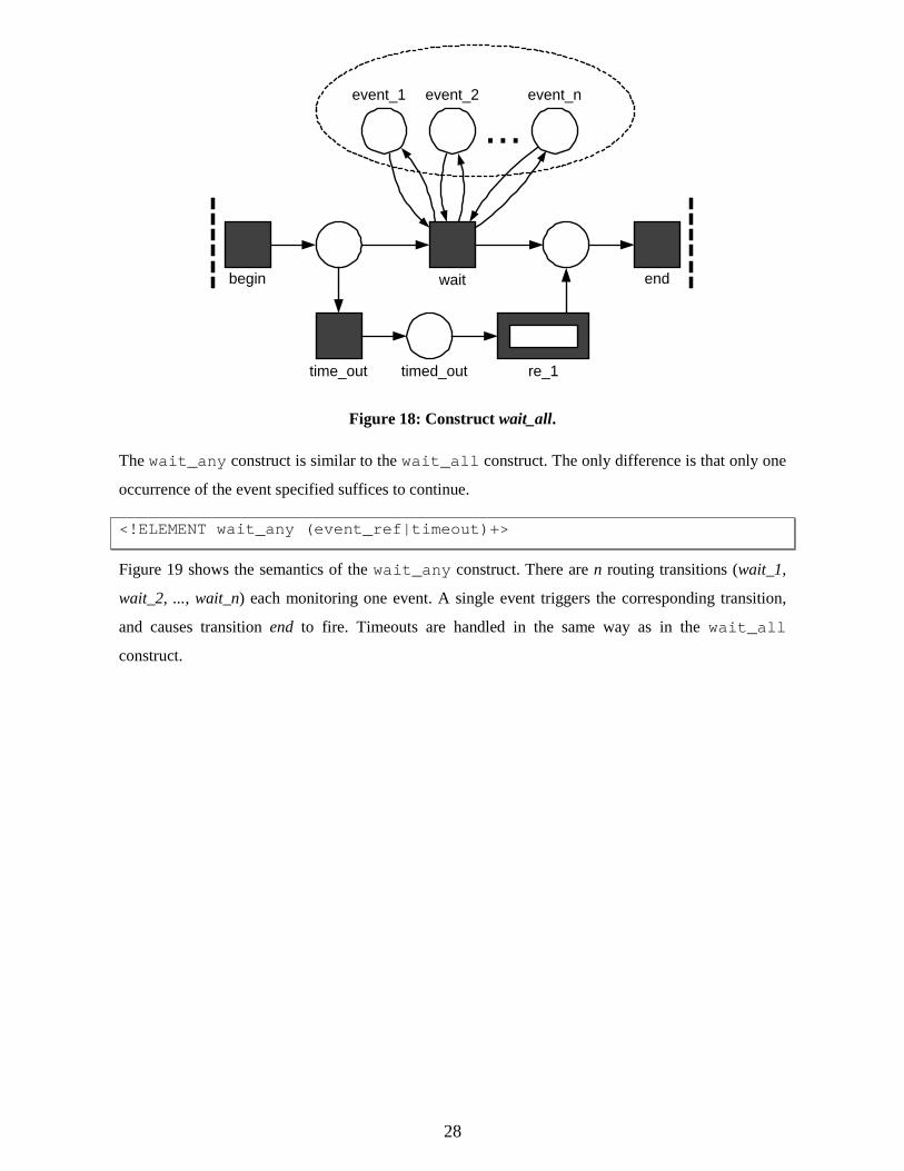
Events are global, i.e., an event generated by a task is visible for all wait_all/wait_any
constructs. In Figure 18 it is assumed that there is exactly one timeout element (represented by
re_1) and there are n events (represented by places event_1, event_2, ..., event_n). After executing
transition begin either transition wait fires because all places event_1, event_2, ..., event_n are marked
or transition timeout fires because the time specified is reached. If transition wait fires, then the
routing element wait_all terminates and triggers subsequent routing elements. If transition timeout
fires, routing element re_1 is executed before subsequent routing elements are triggered. Note that
transition wait returns the tokens consumed from the places event_1, event_2, ..., event_n. These
tokens are returned because there may be other wait_all/wait_any constructs waiting for the
same event. If there are no timeouts, the bottom part of Figure 18 is removed. If there are multiple
timeouts, the bottom part is repeated, i.e., there are multiple timeout routing transitions connected to a
shared input place.
28
time_out re_1timed_out
begin endwait
...event_1 event_2 event_n
Figure 18: Construct wait_all.
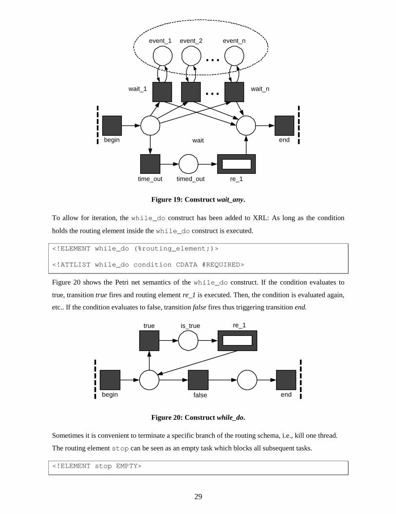
The wait_any construct is similar to the wait_all construct. The only difference is that only one
occurrence of the event specified suffices to continue.
<!ELEMENT wait_any (event_ref|timeout)+>
Figure 19 shows the semantics of the wait_any construct. There are n routing transitions (wait_1,
wait_2, ..., wait_n) each monitoring one event. A single event triggers the corresponding transition,
and causes transition end to fire. Timeouts are handled in the same way as in the wait_all
construct.
29
time_out re_1timed_out
begin endwait
...event_1 event_2 event_n
wait_1 wait_n...
Figure 19: Construct wait_any.
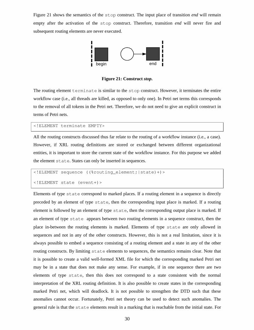
To allow for iteration, the while_do construct has been added to XRL: As long as the condition
holds the routing element inside the while_do construct is executed.
<!ELEMENT while_do (%routing_element;)>
<!ATTLIST while_do condition CDATA #REQUIRED>
Figure 20 shows the Petri net semantics of the while_do construct. If the condition evaluates to
true, transition true fires and routing element re_1 is executed. Then, the condition is evaluated again,
etc.. If the condition evaluates to false, transition false fires thus triggering transition end.
false
re_1true is_true
begin end
Figure 20: Construct while_do.
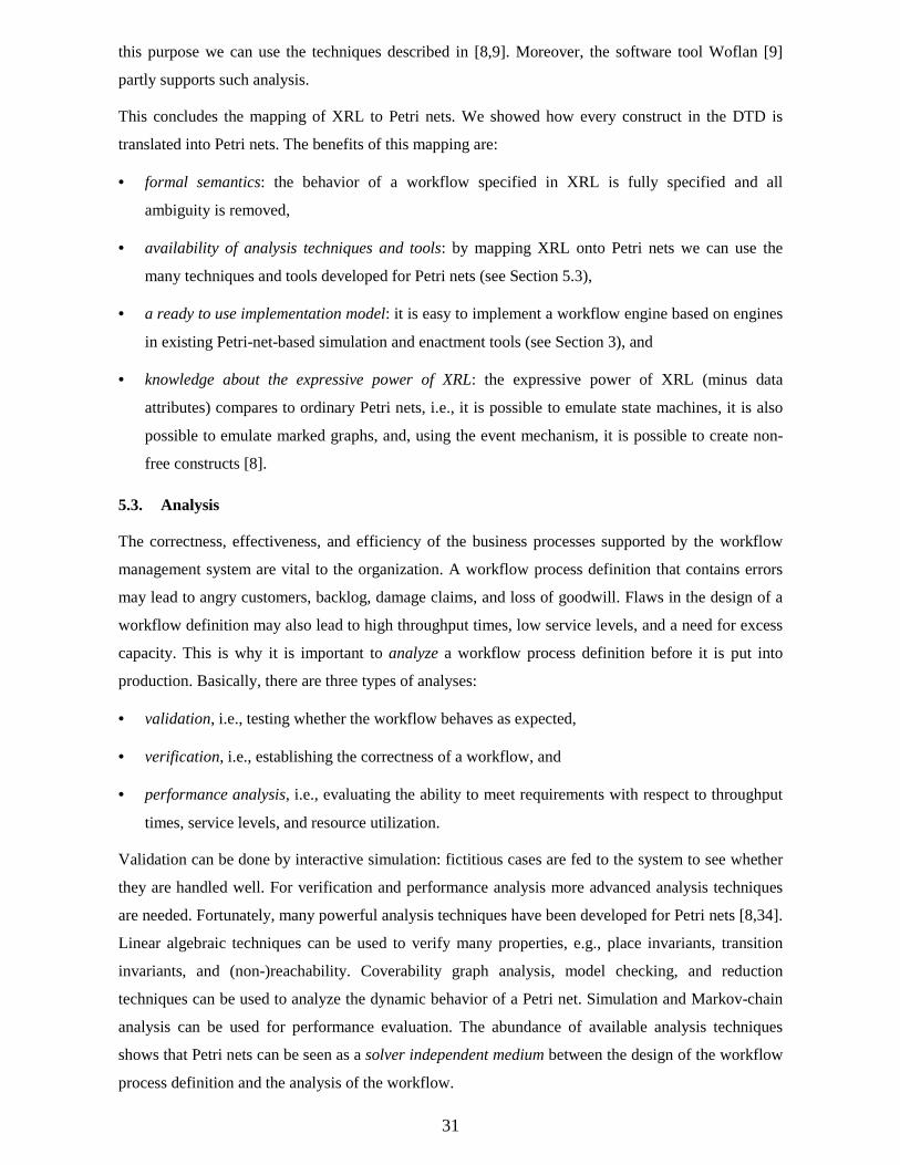
Sometimes it is convenient to terminate a specific branch of the routing schema, i.e., kill one thread.
The routing element stop can be seen as an empty task which blocks all subsequent tasks.
<!ELEMENT stop EMPTY>
30
Figure 21 shows the semantics of the stop construct. The input place of transition end will remain
empty after the activation of the stop construct. Therefore, transition end will never fire and
subsequent routing elements are never executed.
begin end
Figure 21: Construct stop.
The routing element terminate is similar to the stop construct. However, it terminates the entire
workflow case (i.e., all threads are killed, as opposed to only one). In Petri net terms this corresponds
to the removal of all tokens in the Petri net. Therefore, we do not need to give an explicit construct in
terms of Petri nets.
<!ELEMENT terminate EMPTY>
All the routing constructs discussed thus far relate to the routing of a workflow instance (i.e., a case).
However, if XRL routing definitions are stored or exchanged between different organizational
entities, it is important to store the current state of the workflow instance. For this purpose we added
the element state. States can only be inserted in sequences.
<!ELEMENT sequence ((%routing_element;|state)+)>
<!ELEMENT state (event+)>
Elements of type state correspond to marked places. If a routing element in a sequence is directly
preceded by an element of type state, then the corresponding input place is marked. If a routing
element is followed by an element of type state, then the corresponding output place is marked. If
an element of type state appears between two routing elements in a sequence construct, then the
place in-between the routing elements is marked. Elements of type state are only allowed in
sequences and not in any of the other constructs. However, this is not a real limitation, since it is
always possible to embed a sequence consisting of a routing element and a state in any of the other
routing constructs. By limiting state elements to sequences, the semantics remains clear. Note that
it is possible to create a valid well-formed XML file for which the corresponding marked Petri net
may be in a state that does not make any sense. For example, if in one sequence there are two
elements of type state, then this does not correspond to a state consistent with the normal
interpretation of the XRL routing definition. It is also possible to create states in the corresponding
marked Petri net, which will deadlock. It is not possible to strengthen the DTD such that these
anomalies cannot occur. Fortunately, Petri net theory can be used to detect such anomalies. The
general rule is that the state elements result in a marking that is reachable from the initial state. For
31
this purpose we can use the techniques described in [8,9]. Moreover, the software tool Woflan [9]
partly supports such analysis.
This concludes the mapping of XRL to Petri nets. We showed how every construct in the DTD is
translated into Petri nets. The benefits of this mapping are:
• formal semantics: the behavior of a workflow specified in XRL is fully specified and all
ambiguity is removed,
• availability of analysis techniques and tools: by mapping XRL onto Petri nets we can use the
many techniques and tools developed for Petri nets (see Section 5.3),
• a ready to use implementation model: it is easy to implement a workflow engine based on engines
in existing Petri-net-based simulation and enactment tools (see Section 3), and
• knowledge about the expressive power of XRL: the expressive power of XRL (minus data
attributes) compares to ordinary Petri nets, i.e., it is possible to emulate state machines, it is also
possible to emulate marked graphs, and, using the event mechanism, it is possible to create non-
free constructs [8].
5.3. Analysis
The correctness, effectiveness, and efficiency of the business processes supported by the workflow
management system are vital to the organization. A workflow process definition that contains errors
may lead to angry customers, backlog, damage claims, and loss of goodwill. Flaws in the design of a
workflow definition may also lead to high throughput times, low service levels, and a need for excess
capacity. This is why it is important to analyze a workflow process definition before it is put into
production. Basically, there are three types of analyses:
• validation, i.e., testing whether the workflow behaves as expected,
• verification, i.e., establishing the correctness of a workflow, and
• performance analysis, i.e., evaluating the ability to meet requirements with respect to throughput
times, service levels, and resource utilization.
Validation can be done by interactive simulation: fictitious cases are fed to the system to see whether
they are handled well. For verification and performance analysis more advanced analysis techniques
are needed. Fortunately, many powerful analysis techniques have been developed for Petri nets [8,34].
Linear algebraic techniques can be used to verify many properties, e.g., place invariants, transition
invariants, and (non-)reachability. Coverability graph analysis, model checking, and reduction
techniques can be used to analyze the dynamic behavior of a Petri net. Simulation and Markov-chain
analysis can be used for performance evaluation. The abundance of available analysis techniques
shows that Petri nets can be seen as a solver independent medium between the design of the workflow
process definition and the analysis of the workflow.
32
Today’s workflow management systems provide limited support for performance analysis. Most
provide a rudimentary simulator or a gateway to a simulation tool. Simulation can be used to estimate
key performance indicators by experimenting with the specified workflow under the assumption of a
specific behavior of the environment. Examples of key performance indicators are average throughput
time of cases, average waiting time, occupation rates of resources, service levels, and the average
number of pending cases.
Moreover, most workflow management systems also do not support verification of workflows. As a
result, workflow process definitions become operational before they are thoroughly checked for
correctness. This often results in runtime errors that need on-the-fly repair at high costs. Both
manufacturers and users of workflow management systems see the need for analysis tools that take
care of the verification. It is especially important in the context of inter-organizational workflows to
be able to detect potential anomalies before they occur. Unfortunately, most vendors do not have the
technology to build such tools.
The SMIS group of Eindhoven University of Technology developed two software products: ExSpect
and Woflan. ExSpect (http://www.exspect.com) is a simulation tool based on Petri nets which can
interface with workflow products such as COSA (Software Ley), BaanERP/DEM (Baan), and Protos
(Pallas Athena). Woflan (http://www.win.tue.nl/~woflan/) is a workflow verification tool which uses
state-of-the-art Petri-net-based techniques to verify the correctness of a workflow specification.
Woflan is designed as a WFMS-independent analysis tool. In principle it can interface with many
workflow management systems. At the moment, Woflan can interface with the workflow products
COSA (Software Ley ), METEOR (LSDIS), and Staffware (Staffware), and the BPR-tool Protos
(Pallas Athena). The fact that we provided a translation from XRL to Petri nets allows us, in principle,
to use both ExSpect and Woflan. Currently, we are working on an automatic translation from XRL to
Woflan. It is fairly straightforward given the mapping presented in this section.
6. Complete Examples
Now we turn to show how these various constructs can be integrated to design a complete workflow
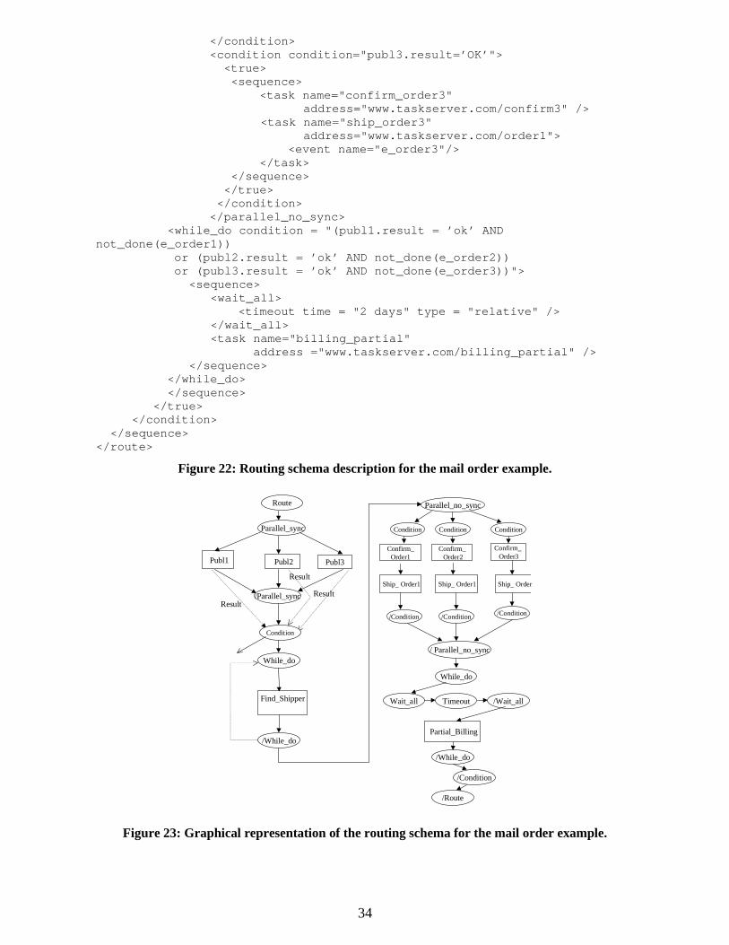
routing schema for the mail order processing example described in Section 2.2. Figure 22 gives the
XRL description while Figure 23 shows a graphical representation. The various control constructs are
shown within ovals in Figure 23, while the actual tasks or steps are inside rectangles.
The route element denotes the start of the route. It has a reference attribute to uniquely identify an
instance. Next there is a parallel_sync element which contains three branches. In each branch an
inquiry is made with a publisher about whether it can provide a book in a timely manner. These three
inquires are made in parallel. After the parallel_sync construct finishes the condition element
checks if at least two of the publisher inquiry steps were completed with a result value of "ok". If so,
the while_do loop is used to find a shipper. The loop is required because if the first shipper that is
contacted is unable to perform the work then another one may have to be contacted, presumably from
33
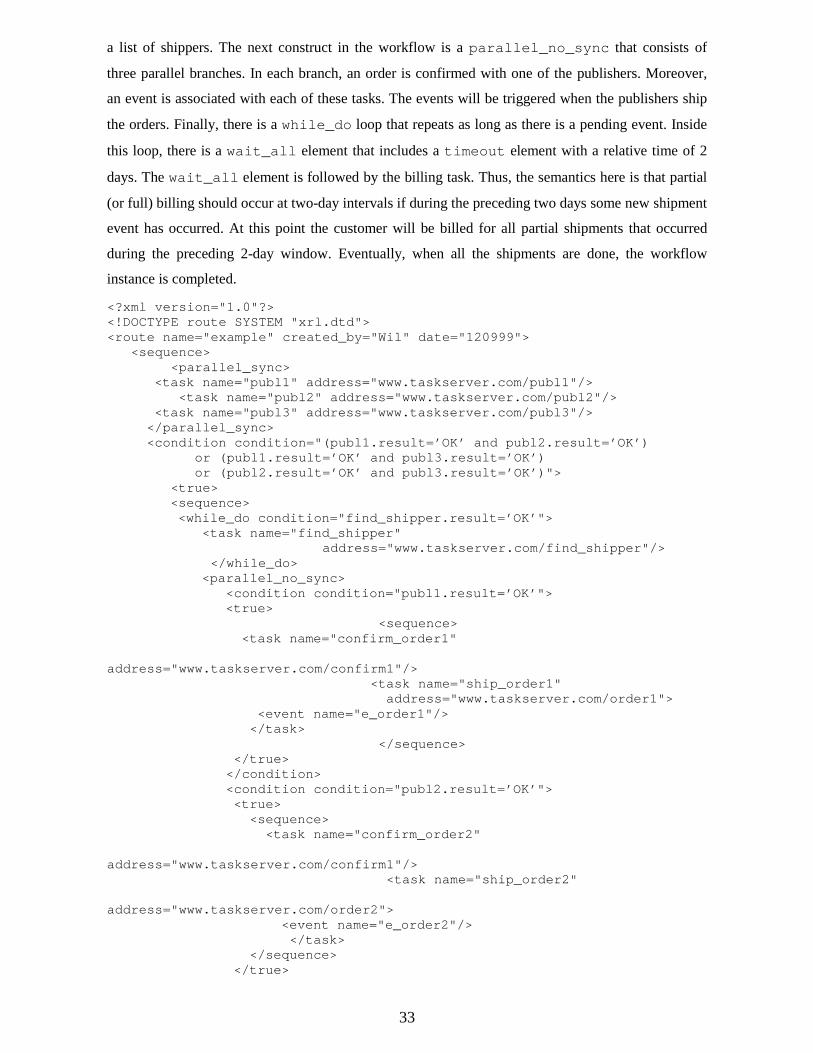
a list of shippers. The next construct in the workflow is a parallel_no_sync that consists of
three parallel branches. In each branch, an order is confirmed with one of the publishers. Moreover,
an event is associated with each of these tasks. The events will be triggered when the publishers ship
the orders. Finally, there is a while_do loop that repeats as long as there is a pending event. Inside
this loop, there is a wait_all element that includes a timeout element with a relative time of 2
days. The wait_all element is followed by the billing task. Thus, the semantics here is that partial
(or full) billing should occur at two-day intervals if during the preceding two days some new shipment
event has occurred. At this point the customer will be billed for all partial shipments that occurred
during the preceding 2-day window. Eventually, when all the shipments are done, the workflow
instance is completed.
<?xml version="1.0"?><!DOCTYPE route SYSTEM "xrl.dtd"><route name="example" created_by="Wil" date="120999"> <sequence> <parallel_sync>
<task name="publ1" address="www.taskserver.com/publ1"/> <task name="publ2" address="www.taskserver.com/publ2"/>
<task name="publ3" address="www.taskserver.com/publ3"/> </parallel_sync> <condition condition="(publ1.result=’OK’ and publ2.result=’OK’)
or (publ1.result=’OK’ and publ3.result=’OK’) or (publ2.result=’OK’ and publ3.result=’OK’)">
<true> <sequence>
<while_do condition="find_shipper.result=’OK’"> <task name="find_shipper"
address="www.taskserver.com/find_shipper"/> </while_do>
<parallel_no_sync> <condition condition="publ1.result=’OK’">
<true> <sequence>
<task name="confirm_order1"
address="www.taskserver.com/confirm1"/> <task name="ship_order1" address="www.taskserver.com/order1">
<event name="e_order1"/> </task>
</sequence> </true>
</condition> <condition condition="publ2.result=’OK’">
<true> <sequence> <task name="confirm_order2"
address="www.taskserver.com/confirm1"/> <task name="ship_order2"
address="www.taskserver.com/order2"> <event name="e_order2"/>
</task> </sequence> </true>
34
</condition> <condition condition="publ3.result=’OK’">
<true> <sequence> <task name="confirm_order3"
address="www.taskserver.com/confirm3" /> <task name="ship_order3" address="www.taskserver.com/order1">
<event name="e_order3"/> </task> </sequence> </true>
</condition> </parallel_no_sync>
<while_do condition = "(publ1.result = ’ok’ ANDnot_done(e_order1)) or (publ2.result = ’ok’ AND not_done(e_order2))
or (publ3.result = ’ok’ AND not_done(e_order3))"> <sequence> <wait_all> <timeout time = "2 days" type = "relative" /> </wait_all> <task name="billing_partial" address ="www.taskserver.com/billing_partial" /> </sequence>
</while_do> </sequence> </true> </condition> </sequence></route>
Figure 22: Routing schema description for the mail order example.
Result
Parallel_sync
/Parallel_sync
Parallel_no_sync
/ Parallel_no_syncWhile_do
Condition
/While_do
/While_do
While_do
Publ1 Publ2 Publ3
Find_Shipper
Partial_Billing
Confirm_ Order1
Confirm_ Order2
Confirm_ Order3
Route
/Route
Result
Result Ship_ Order1 Ship_ Order1 Ship_ Order
Condition ConditionCondition
/Condition/Condition/Condition
Wait_all Timeout /Wait_all
/Condition
Figure 23: Graphical representation of the routing schema for the mail order example.
35
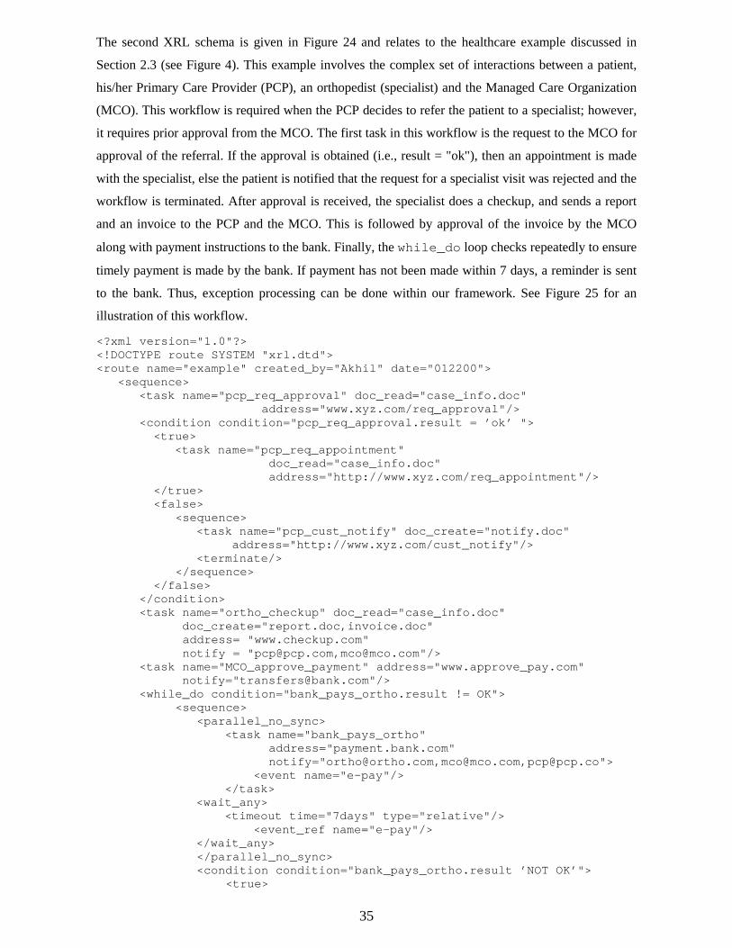
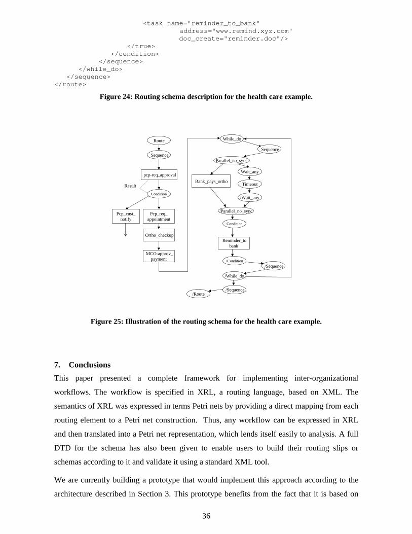
The second XRL schema is given in Figure 24 and relates to the healthcare example discussed in
Section 2.3 (see Figure 4). This example involves the complex set of interactions between a patient,
his/her Primary Care Provider (PCP), an orthopedist (specialist) and the Managed Care Organization
(MCO). This workflow is required when the PCP decides to refer the patient to a specialist; however,
it requires prior approval from the MCO. The first task in this workflow is the request to the MCO for
approval of the referral. If the approval is obtained (i.e., result = "ok"), then an appointment is made
with the specialist, else the patient is notified that the request for a specialist visit was rejected and the
workflow is terminated. After approval is received, the specialist does a checkup, and sends a report
and an invoice to the PCP and the MCO. This is followed by approval of the invoice by the MCO
along with payment instructions to the bank. Finally, the while_do loop checks repeatedly to ensure
timely payment is made by the bank. If payment has not been made within 7 days, a reminder is sent
to the bank. Thus, exception processing can be done within our framework. See Figure 25 for an
illustration of this workflow.
<?xml version="1.0"?><!DOCTYPE route SYSTEM "xrl.dtd"><route name="example" created_by="Akhil" date="012200">
<sequence><task name="pcp_req_approval" doc_read="case_info.doc"
address="www.xyz.com/req_approval"/> <condition condition="pcp_req_approval.result = ’ok’ ">
<true> <task name="pcp_req_appointment"
doc_read="case_info.doc" address="http://www.xyz.com/req_appointment"/>
</true> <false>
<sequence> <task name="pcp_cust_notify" doc_create="notify.doc"
address="http://www.xyz.com/cust_notify"/> <terminate/>
</sequence> </false>
</condition> <task name="ortho_checkup" doc_read="case_info.doc"
doc_create="report.doc,invoice.doc"address= "www.checkup.com"
notify = "[email protected],[email protected]"/> <task name="MCO_approve_payment" address="www.approve_pay.com"
notify="[email protected]"/> <while_do condition="bank_pays_ortho.result != OK">
<sequence> <parallel_no_sync>
<task name="bank_pays_ortho" address="payment.bank.com"
notify="[email protected],[email protected],[email protected]"> <event name="e-pay"/>
</task> <wait_any>
<timeout time="7days" type="relative"/> <event_ref name="e-pay"/>
</wait_any> </parallel_no_sync> <condition condition="bank_pays_ortho.result ’NOT OK’">
<true>
36
<task name="reminder_to_bank" address="www.remind.xyz.com"
doc_create="reminder.doc"/> </true>
</condition> </sequence>
</while_do> </sequence></route>
Figure 24: Routing schema description for the health care example.
Result
Sequence
Condition
While_do
pcp-req_approval
Pcp_req_appointment
Ortho_checkup
Route
Wait_any
Timeout
/Wait_any
MCO-approv_payment
Parallel_no_sync
Bank_pays_ortho
/Parallel_no_sync
Condition
Reminder_tobank
/Condition
/While_do
/Sequence/Route
Sequence
/Sequence
Pcp_cust_notify
Figure 25: Illustration of the routing schema for the health care example.
7. Conclusions
This paper presented a complete framework for implementing inter-organizational
workflows. The workflow is specified in XRL, a routing language, based on XML. The
semantics of XRL was expressed in terms Petri nets by providing a direct mapping from each
routing element to a Petri net construction. Thus, any workflow can be expressed in XRL
and then translated into a Petri net representation, which lends itself easily to analysis. A full
DTD for the schema has also been given to enable users to build their routing slips or
schemas according to it and validate it using a standard XML tool.
We are currently building a prototype that would implement this approach according to the
architecture described in Section 3. This prototype benefits from the fact that it is based on
37
both XML and Petri nets. Standard XML tools can be deployed to parse, check, and handle
XRL documents. The Petri net representation allows for a straightforward and succinct
implementation of the workflow engine. XRL constructs are automatically translated into
Petri net constructs. One the one hand, this allows for an efficient implementation. On the
other hand, the system is easy to extend: For supporting a new routing primitive, only the
translation to the Petri net engine needs to be added and the engine itself does not need to
change. Last-but-not-least, the Petri net representation can be analyzed using state-of-the-art
analysis techniques and tools. For example, given a representation of a workflow in terms of
Petri nets, our verification tool Woflan [8,9] can detect design errors.
References
1. Aalst, W.M.P. van der and K. Anyanwu, "Inheritance of Interorganizational Workflows
to Enable Business-to-Business E-commerce," In Proceedings of the Second International
Conference on Telecommunications and Electronic Commerce (ICTEC’99), pages 141-
157, Nashville, Tennessee, October 1999.
2. Aalst, W.M.P. van der and T. Basten, "Inheritance of Workflows: An approach to
tackling problems related to change," Computing Science Reports 99/06, Eindhoven
University of Technology, Eindhoven, 1999.
3. Aalst, W.M.P. van der, "Generic Workflow Models: How to Handle Dynamic Change
and Capture Management Information." In M. Lenzerini and U. Dayal, editors,
Proceedings of the Fourth IFCIS International Conference on Cooperative Information
Systems (CoopIS’99), pages 115-126, Edinburgh, Scotland, September 1999. IEEE
Computer Society Press.
4. Aalst, W.M.P. van der, T. Basten, H.M.W. Verbeek, P.A.C. Verkoulen, and M.
Voorhoeve. "Adaptive Workflow: On the Interplay between Flexibility and Support." In
J. Filipe and J. Cordeiro, editors, Enterprise Information Systems, pages 61-68. Kluwer
Academic Publishers, Norwell, 2000.
5. Aalst, W.M.P. van der, "Interorganizational Workflows: An Approach based on Message
Sequence Charts and Petri Nets," Systems Analysis - Modelling - Simulation, 34(3):335-
367, 1999.

38
6. Aalst, W.M.P. van der, "Loosely Coupled Interorganizational Workflows: Modeling and
Analyzing Workflows Crossing Organizational Boundaries," Information and
Management, 37(2):67-75, March 2000.
7. Aalst, W.M.P. van der, "Process-oriented Architectures for Electronic Commerce and
Interorganizational Workflow," Information Systems, 24(8), 2000 (in print).
8. Aalst, W.M.P. van der, "The Application of Petri Nets to Workflow Management," The
Journal of Circuits, Systems and Computers, 8(1):21-66, 1998.
9. Aalst, W.M.P. van der, "Woflan: A Petri-net-based Workflow Analyzer," Systems
Analysis - Modelling - Simulation, 35(3):345-357, 1999.
10. Adam, N.R., V. Atluri, and W. Huang, "Modeling and Analysis of Workflows using Petri
Nets," Journal of Intelligent Information Systems, 10(2):131-158, 1998.
11. Alonso, G., C. Mohan, R. Gunthor, D. Agrawal, et.al., "Exotica/FMQM: A persistent
message-based architecture for distributed workflow management," Proceedings of IFIP
Working Conference on Information Systems Development for Decentralized
Organizations (ISDO ’95), Trondheim, Norway, 1-18 (1995).
12. Arntzen, B.C., G.G. Brown, T.P. Harrison, and L.L. Trafton, "Global supply chain
management at Digital Equipment Corporation," Interfaces Vol.25, no.1, 69-93 (1995).
13. Barbuceanu and Fox., "Coordinating multiple agents in the supply chain," Proceedings of
the 5th Workshop on Enabling Technologies: Infrastructure for Collaborative Enterprises,
June 1996.
14. Bray, T., J. Paoli, and C.M. Sperberg-McQueen, "Extensible Markup Language (XML)
1.0", REC-xml-19980210, http://www.w3.org/TR/REC-xml, W3C, 1998.
15. Ellis, C.A. and G.J. Nutt, "Modelling and Enactment of Workflow Systems," In M.
Ajmone Marsan, editor, Application and Theory of Petri Nets 1993, Volume 691 of
Lecture Notes in Computer Science, pages 1-16, Springer-Verlag, Berlin, 1993.
16. Fan, M., J. Stallaert and A.B. Whinston, "A Web-based Financial Trading System," IEEE
Computer, Volume 32, No. 4, April 1999.
17. Fingar, P., "Enterprise Architecture for Open Ecommerce," Component Strategies,
February 1999.
18. Ford. W. and M. Baum, Secure Electronic Commerce, Prentice-Hall, (1997).
39
19. Georgakopoulos, D., M. Hornick, and A. Sheth, "An overview of workflow management:
from process modelling to workflow automation infrastructure," Distributed and Parallel
Databases, vol. 3, no. 2, 119-153 (1995).
20. Ghundavaram, S., CGI Programming on the Worldwide Web, O’Reilly, (1996).
21. Glushko, R., J. Tenenbaum and B. Meltzer, "An XML framework for agent-based E-
commerce," Communications of ACM, Vol. 42, No. 3, March 1999.
22. IEEE Computer, Special Issue on Electronic Commerce, vol. 30, no. 5, May (1997).
23. Jablonski, S. and C. Bussler, "Workflow Management: Modeling Concepts, Architecture,
and Implementation," International Thomson Computer Press, London, UK, 1996.
24. Jutla, D., et.al, "Making business sense of Electronic Commerce," IEEE Computer,
Volume 32, No. 3, March 1999.
25. Kalakota, R. and A.B. Whinston, Frontiers of Electronic Commerce, Addison-Wesley,
Reading, Massachusetts, 1996.
26. Keller, G and T. Teufel, SAP R/3 Process-oriented Implementation, Addison Wesley,
1988.
27. Krol, E., The Whole Internet, O’Reilly and Associates, Second ed. (1994).
28. Kumar, A. and Zhao, J.L. "Dynamic Routing and Operational Integrity Controls in a
Workflow Management System," Management Science, Volume 45, No. 2, February
1999, 253-272.
29. Lawrence, P., editor. Workflow Handbook 1997, Workflow Management Coalition. John
Wiley and Sons, New York, 1997.
30. Lee, H.L. and C. Billington, "The evolution of supply-chain-management models and
practice at Hewlett-Packard," Interfaces vol.25, no.5, 42-63 (1995).
31. Lee, R.M., "Distributed Electronic Trade Scenarios: Representation, Design,
Prototyping," International Journal of Electronic Commerce, 3(2):105-120, 1999.
32. Maes, P., et al., "Agents that buy and sell," Communications of ACM, Vol. 42, No. 3,
March 1999.
33. Merz, M., et al. "Supporting electronic commerce transactions with contracting services."
International Journal of Cooperative Information Systems, Dec. 1998, vol.7, (no.4):249-
74.
40
34. Reisig, W. and G. Rozenberg, editors, Lectures on Petri Nets I: Basic Models, Volume
1491 of Lecture Notes in Computer Science, Springer-Verlag, Berlin, 1998.
35. Segev, A., J. Porra and M. Roldan. "Internet-based EDI strategy," Decision Support
Systems, Nov. 1997, Vol.21, (No.3):157-70.
36. Sheth, A.P., W.M.P. van der Aalst and I.B. Arpinar, "Processes Driving the Networked
Economy: ProcessPortals, ProcessVortex, and Dynamically Trading Processes," IEEE
Concurrency, 7(3):18-31, 1999.
37. Sorenson, J. and L. Wood, "Document Object Model Requirements," WWW
Consortium," http://www.w3.org/TR/WD-DOM/requirements.html, (1998).
38. St. Laurent, S., XML: A Primer, New York : MIS: Press, (1997).
39. Teich, J., H. Wallenius and J. Wallenius, "World-Wide-Web technology in support of
negotiation and communication," International Journal of Technology Management,
1999, vol.17, (no.1-2): 223-38.
40. Zwass, V., "Electronic commerce: structures and issues," International Journal of
Electronic Commerce, 1(1):3-23, 1996.
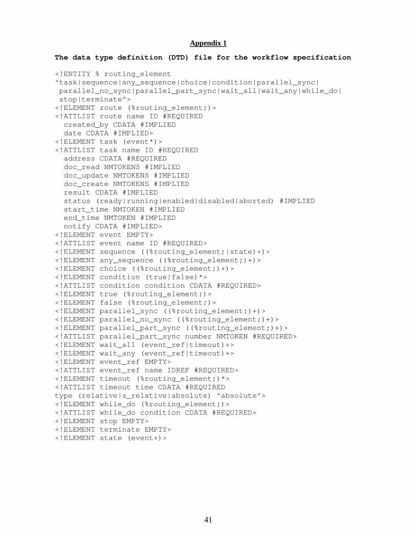
41
Appendix 1
The data type definition (DTD) file for the workflow specification
<!ENTITY % routing_element"task|sequence|any_sequence|choice|condition|parallel_sync| parallel_no_sync|parallel_part_sync|wait_all|wait_any|while_do| stop|terminate"><!ELEMENT route (%routing_element;)><!ATTLIST route name ID #REQUIRED created_by CDATA #IMPLIED date CDATA #IMPLIED><!ELEMENT task (event*)><!ATTLIST task name ID #REQUIRED address CDATA #REQUIRED doc_read NMTOKENS #IMPLIED doc_update NMTOKENS #IMPLIED doc_create NMTOKENS #IMPLIED result CDATA #IMPLIED status (ready|running|enabled|disabled|aborted) #IMPLIED start_time NMTOKEN #IMPLIED end_time NMTOKEN #IMPLIED notify CDATA #IMPLIED><!ELEMENT event EMPTY><!ATTLIST event name ID #REQUIRED><!ELEMENT sequence ((%routing_element;|state)+)><!ELEMENT any_sequence ((%routing_element;)+)><!ELEMENT choice ((%routing_element;)+)><!ELEMENT condition (true|false)*><!ATTLIST condition condition CDATA #REQUIRED><!ELEMENT true (%routing_element;)><!ELEMENT false (%routing_element;)><!ELEMENT parallel_sync ((%routing_element;)+)><!ELEMENT parallel_no_sync ((%routing_element;)+)><!ELEMENT parallel_part_sync ((%routing_element;)+)><!ATTLIST parallel_part_sync number NMTOKEN #REQUIRED><!ELEMENT wait_all (event_ref|timeout)+><!ELEMENT wait_any (event_ref|timeout)+><!ELEMENT event_ref EMPTY><!ATTLIST event_ref name IDREF #REQUIRED><!ELEMENT timeout (%routing_element;)*><!ATTLIST timeout time CDATA #REQUIREDtype (relative|s_relative|absolute) "absolute"><!ELEMENT while_do (%routing_element;)><!ATTLIST while_do condition CDATA #REQUIRED><!ELEMENT stop EMPTY><!ELEMENT terminate EMPTY><!ELEMENT state (event+)>