ÜxÅo« ë@ ª'ÅõaÉ äu !k î)h£files.support.epson.com/pdf/c82314/c82314u1.pdf ·...
TRANSCRIPT

EPSON®
C o a xInterface Card
C82314 ✽
USER’S GUIDEB E D I E N U N G S A N L E I T U N GM O D E D ’ E M P L O IGUÍA DEL USUARIOMANUALE PER L’UTENTE

COPYRIGHT NOTICE:
All rights reserved. No part of this publication may be reproduced, stored in aretrieval system, or transmitted in any form without the prior written permissionof Seiko Epson Corporation. No patent liability is assumed with respect to the useof the information contained herein. While every precaution has been taken in thepreparation of this book, Seiko Epson Corporation assumes no responsibility forerrors or omissions. Neither is any liability assumed for damages resulting fromthe use of the information contained herein.
Neither Seiko Epson Corporation nor its affiliates shall be liable to the purchaserof this product or third parties for damages, losses, costs, or expenses incurredby the purchaser or third parties as a result of: accident, misuse, or abuse of thisproduct or unauthorized modifications, repairs, or alterations to this product, or(excluding the U.S.) failure to strictly comply with Seiko Epson Corporation’soperating and maintenance instructions.
Epson and Epson ESC/P are registered trademarks of Seiko Epson Corporation.IBM is a registered trademark of International Business Machines Corporation.HP LaserJet is a trademark, and Hewlett-Packard and PCL are registeredtrademarks of Hewlett-Packard Company.Centronics is a registered trademark of Centronics Data Computer Corporation.PostScript is a trademark of Adobe Systems incorporated.Command-Pass-Thru is a registered trademark of I-O Corporation.WordPerfect is a registered trademark of WordPerfect Corporation.Microsoft is a registered trademark of Microsoft Corporation.Univers, Times, and Helvetica are registered trademarks of Linotype AG and itssubsidiaries.CG Times, CG Century Schoolbook, and Microstyle are products and CGTriumvirate is a trademark of AGFA Compugraphic, a Division of Agfa Corporation.Serifa is a trademark of Fundicion Tipografica Neufville, S.A.ITC Dingbats is a U.S. registered trademark of International Typeface Corporation.
General Notice: Other product names used herein are for identification purposesonly and may be trademarks of their respective companies.
Copyright © 1992 by Seiko Epson CorporationNagano, Japan

FCC COMPLIANCE STATEMENTFOR AMERICAN USERS
This equipment has bean tested and found to comply with the limits fora Class A digital device. pursuant to Part 15 of the FCC Rules. Theselimits are designed to provide reasonable protection against harmfulinterference when the equipment is operated in a commercialenvironment. This equipment generates, uses, and can radiate radiofrequency energy and, if not Installed and used in accordance with theinstruction manual, may cause harmful interference in which case theuser will be required to correct the interference at MS own expense.
This devise complies with Part 15 of the FCC Rules. Operation issubject to the following two conditions: (1) This device may not causeharmful interference, and (2) this device must accept any interferencereceived, including interference that may cause undesired operation.
FOR CANADIAN USERS
This digital apparatus does not exceed the Class A limits for radio noiseemissions from digital apparatus as set out in the radio interferenceregulations of the Canadian Department of Communications.
Le présent appareil numérique n'émet pas de bruits radioélectriquesd&passant les limits applicables aux appareils numériques de Class Aprescrites dans le réglement sur le brouillage radioélectrique édicté parle Ministére des Communications du Canada.
WARNING
The connection of a non-shielded equipment interface cable to thisequipment will invalldate the FCC Certification of this device and maycause interference levels which exceed the limits established by theFCC for this equipment. It is the responsibility of the user to obtain anduse a shielded equipment interface cable with this device. When thisequipment is attached to some printers, you should not leave cablesconnected to the printer’s built-In connectors. See your printer’s user’smanual for details.
Changes or modifications not expressly approved by Seiko EpsonCorporation, could void the user’s authority to operate the equipment.

COAX INTERFACE CARD C82314*
USER’S GUIDE
SCHNITTSTELLENDARTE COAX C82314*
BEDIENUNGSANLEITUNG
CARTE D’INTERFACE COAX C82314*
MODE D’EMPLOI
TARJETA DE INTERFACE COAX C82314*
GUIA DEL USUARIO
SCHEDA DI INTERFACCIA COAX C82314*
MANUALE PER L’UTENTE
APPENDIX CANHANG C/APPENDICE C/APÉNDICE C/APPENDICE C

EPSON Coax Interface
Card C82314*
User’s Guide
Introduction . . . . . . . . . . . . . . . . . . . . . . . . . . . . . . . . . . . . . . . . . . . . . . 1
General Specifications . . . . . . . . . . . . . . . . . . . . . . . . . . . . . . . . . . . . . . . 2LED Specifications . . . . . . . . . . . . . . . . . . . . . . . . . . . . . . . . . . . 2Button Specifications . . . . . . . . . . . . . . . . . . . . . . . . . . . . . . . . . 3
Installation . . . . . . . . . . . . . . . . . . . . . . . . . . . . . . . . . . . . . . . . . . . . . . . 3Contents of Interface Kit . . . . . . . . . . . . . . . . . . . . . . . . . . . . . . . 3Installing the Interface Card . . . . . . . . . . . . . . . . . . . . . . . . . . . . 4Executing a Self-test . . . . . . . . . . . . . . . . . . . . . . . . . . . . . . . . . . 4
Interface Configuration . . . . . . . . . . . . . . . . . . . . . . . . . . . . . . . . . . . . . . 5
Restoring Factory Default Configuration . . . . . . . . . . . . . . . . . . . . . . . . . . 6
Printer Feature Access Methods . . . . . . . . . . . . . . . . . . . . . . . . . . . . . . . . 61. Command-pass-thru . . . . . . . . . . . . . . . . . . . . . . . . . . . . . . . 62. Custom User Strings . . . . . . . . . . . . . . . . . . . . . . . . . . . . . . . 83. SCS Mode Transparent Data . . . . . . . . . . . . . . . . . . . . . . . . . 8
Alternate Host (PC) Auto Parallel Sharing . . . . . . . . . . . . . . . . . . . . . . . . . 9
Parallel Interface Specification . . . . . . . . . . . . . . . . . . . . . . . . . . . . . . . . . 10
Epson HP Laserjet Emulation . . . . . . . . . . . . . . . . . . . . . . . . . . . . . . . . . . 13
HP Font Identifier Codes . . . . . . . . . . . . . . . . . . . . . . . . . . . . . . . . . . . . . 14
Computer Output Reduction (COR), HP Emulation . . . . . . . . . . . . . . . . . . 15
Automatic Print Orientation (APO), HP Emulation . . . . . . . . . . . . . . . . . . . . 16Page Orientation Logic . . . . . . . . . . . . . . . . . . . . . . . . . . . . . . . . 17
Appendix A. Host Download Configuration Commands
Appendix B. Push Button Setup
Appendix C. Sample PrintoutsFont IDS

INTRODUCTION
The Epson 3270 coax interface card C82314* with PC auto parallel sharing portis an optional Epson interface card. It allows the direct connection of supportedEpson ESC/P dot matrix and laser printers to a coax type-A adapter of an IBM3174/3274/3276 Control Unit or IBM 3270 mainframe system. In addition, aCentronics compatible mini-parallel port with auto switching allows a PC oralternate host to share the printer with the 3270 host for optimum printerutilization.
The Epson interface can emulate IBM 3287, 3268, 4214-1, and 4224 (non-IPDS)dot matrix printers and IBM 3812-1 and 4028 (non-IPDS) laser printers. When theinterface is installed in an Epson printer with HP LaserJet emulation, the ComputerOutput Reduction (COR) feature enables data processing reports to automaticallybe reduced and printed on letter size paper. Also, custom Font ID’s allow you tospecify multiple fonts that will automatically be used in your documents.
The Epson interface supports LU3 (DSC) and LUl .(SCS) mode printing. It has alarge selection of user definable setup selections (including IBM RPQ options) thatcan be changed and stored in non-volatile memory using commands imbeddedin documents sent to the printer (downloaded from the host). A CommandPass-Thru (hex transparency) feature allows a user to access the special featuresof the Epson printer directly from the coax host. The interface does not supportcoax host-controlled color printing options, AFP, IPDS, GDDM, APL, programmedsymbols.
Epson printers that have a slot for an optional interface card are supported:
DLQ-2000 LQ-570/1070SQ-870/1 170 EPL-4000/4100ActionPrinter 5000/5500 ActionLaserll
LQ870/1170EPL-8000/8100
Note: See your printer’s User’s Guide for information on the optional interfacesit supports. Contact your Epson dealer for further information on C82314*interface support.

GENERAL SPECIFICATIONS
Input Protocol: IBM 3270 coax LU1 or LU3 protocol and Centronicsparallel protocol
Output Protocol: Epson parallel, internal interface connection
Receive Data Rate: Maximum burst: 2.3587 million bits/second
Data Buffering: 4K byte coax communication buffer
Language Support: Standard IBM 3174 language sections (SeeAppendix A, Command 8 for list of languages.)
Connectors: Female BNC coax connector and mini-Centronicsparallel connector for alternate host (PC) sharing
Indicators: One red LEDOne green LED
Switches: Two push buttons
Power Required: +5V @ 240mA, supplied by the printer
LED SPECIFICATIONS
LED Indication
Green ON
Green OFF
Red ON
Red BlinksTwice
Red Remainson after turn on
status
The control unit (CU) is communicating with the interface card(within past 30 seconds).
The CU is not communicating with the interface card.
The program attention (PA) manual option (see Appendix A,command 35) is active and the printer received a request (fromthe host software) for a PA button to be pressed by the user soprinting can continue.
The user pressed and released both buttons at the same time(for less than 1 second) sending a cancel message to the host.
The interface encountered problems during its self test.(The red LED goes off after a normal self test.)

BUTTON SPECIFICATIONS
Button
Top
Bottom
Both
Functions
PA1 response when the PA red LED is on
Prints out a page listing when pressed and held for 2 seconds. If thecoax cable is disconnected, then a RAM/ROM self test is alsoperformed and the results are printed.
YES response during push button setup (see Appendix B)
PA2 response when the PA red LED is on
Begins restoration of factory default setup (see “Restoring FactoryDefault Configuration’ section)
NO response during push button setup (see Appendix B)
After turning on, if both buttons are pressed and released (for lessthan one second) a cancel signal is sent to the host. The red LEDwill blink twice times to confirm the cancel signal was sent. (Note:The printer will continue printing until its buffer is empty.)
After turning on, if both buttons are pressed and held more than twoseconds, the interface enters the hexadecimal (buffer dump)diagnostic printing mode. The printer then prints “Buffer print isactive’ and the green LED will blink twice. Turn off the printer to exitthis mode or press and hold both buttons for more than two secondswhich will cause the green LED to blink twice. (Also, see Command42 in Appendix A for a download command.)
I N S T A L L A T I O N
CONTENTS OF INTERFACE KIT
Make sure the interface kit includes all items listed below:
Coax interface cardPC Auto Parallel Sharing CableUser’s guide

INSTALLING THE INTERFACE CARD
Install the coax interface card in the same way as any Epson optional interface.This procedure is explained in detail for the individual Epson printers in either anappendix or the section on Using Printer Options in the user’s manual that comeswith the printer. Please follow the instructions carefully to install the coax interfacecard. Secure the interface with the thumb screws. Take precautions to protect theinterface card from static discharge by touching a grounded surface immediatelybefore installing.
The mini-Centronics connector on the coax interface card can be used forautomatic alternate host (PC) sharing by using the parallel printer share cableincluded in the box with the interface.
The interface card is supplied with default setup selections stored in its nonvolatilememory. These default selections will suffice for most user requirements. Referto Appendix A for a listing of the user definable setup selections and customfeatures.
EXECUTING A SELF-TEST
Verify proper installation of the coax interface card by performing an interface cardself-test. The self-test also prints out the current setup selections.
1. Before testing the interface card, perform a test of the printer to confirmthat it is functional. Refer to instructions in the printer’s User’s Guide. Donot proceed unless the printer is operational.
2. To test the coax interface, disconnect the coax and mini-Centronicsconnectors from the interface and turn the printer on. After the printer isready, press the top (PA1) button on the interface and hold it for morethan two seconds. Release the button and the self test results are printedas well as a listing of the setup selections.
3. The printer prints out the self-test page if the interface is installedproperly. See the self test printout example, Appendix C.
4. If nothing prints, the interface is not installed properly. A separate test ofthe interface may be performed by disconnecting the coax and mini-Centronics connectors and turning on the printer. If the LED displays redand then goes out, it indicates successful completion of the self tests. Ifthe red LED remains on, the self tests found a problem with the interface.
A

INTERFACE CONFIGURATION
After installing the interface card and performing a self-test, the interface is readyto operate in most environments. The factory default settings will be satisfactoryfor most programs and applications. Be sure to check Command 60 on the selftest print out to confirm that the interface is configured correctly for either a dotmatrix or HP laser printer.
If you are using a laser printer, make sure you set your printer’s emulation modeto match that of the interface: HP emulation or dot matrix emulation. (If yourlaser printer supports Epson Job Language --EJL- commands, do not change theprinter’s emulation mode using the EJL command or the command-pass-thrufeature while this interface is installed. Also, you may not be able to change theprinter mode using the control panel.)
If your printer prints a warning message, the interface and printer emulations donot match. Use your printer’s control panel to match the interface and printeremulation settings.
Never select the PostScriptTM printer mode while this interface is installed.
If the printer is a matrix printer, you must select character set ‘Code Page 850’ inthe setup of the printer. Refer to the printer’s User’s Guide to determine how toselect the character set by using either dip switches or the front panel. If youhave selected HP LaserJet emulation, the ‘Roman 8’ character set is automaticallyselected.
All configuration selections can be changed by simply embedding commands (asdefined in Appendix A) in a 3270 print job or print screen (hard copy) that is sentto the printer. These are called Host Download Commands. If the embeddedcommand is sent correctly, the characters that create the command are notprinted. If the command is printed, then the interface did not recognize thecommand because of a problem in the format of the command. Correct theproblem and send the command again. If you wish to confirm the active setupselections for the printer, you can print a listing page by either performing a selftest (pressing and holding the top button for 2 seconds) or sending the ‘98,1’command to the interface.
Unless the ‘99,6’ command is sent to save the active setup in non-volatile (NV)memory, the configuration commands only change the active setup values andare lost when the printer is turned off. By sending a ‘98,1’ command immediatelyafter turning on the printer, you can identify the selections that are stored in NVmemory of the interface.
5

If a coax host Is not available and basic setup selections need to be changed, theinterface has the option of a push button setup as defined in Appendix B. Thisoption enables the basic interface features and RPQ options to be selected.
RESTORING FACTORY DEFAULT CONFIGURATION
The factory default configuration selections can be restored to the NV memory ofthe interface by either sending a Host Download Command ‘98,0’ or by turningon the printer when the coax cable is disconnected and performing the followingsteps (waft for printer to be READY):
1. Press and hold the bottom (PA2) button for more than two seconds andthen release; the red and green LED begin to blink alternately.
2. Press and release the top (PA1) button; only the green LED blinks.
3. Press and release the bottom (PA2) button; the red LED blinks twice.
4. Sequence is complete. Factory defaults are restored to the NV memoryof the interface. Turn the printer off and then back on.
PRINTER FEATURE ACCESS METHODS
This interface features three methods for accessing the special features of Epsonprinters not normally available in the IBM printers being emulated:
Command-Pass-ThruCustom User StringsSCS Mode Transparent Data
Each of these methods is described below.
1. COMMAND-PASS-THRU
DESCRIPTION
The Command-Pass-Thru (Hex Transparency) feature allows the user to accessall of the built-in features of the Epson printer whether or not these features canbe accessed by the IBM host software. Command-Pass-Thru provides a methodof placing printer specific command sequences into the data sent to the printerfrom the host. The coax interface recognizes these special sequences and“Passes the Command Thru’ to the printer. This feature allows the programmer
6

to’ access all of the Epson features such as color printing, superscripts; andsubscripts.
Command-Pass-Thru is accomplished by converting the printer commandsequence into a series of two digit hexadecimal values. For example, an Escapehas a decimal value of 27 and a hexadecimal value of 1B. In Command-Pass-Thru, an Escape is the character ‘1’ followed by the character ‘B’. To allow thecoax interface to recognize the sequence, it is proceeded by a ‘delimitersequence consisting of an ampersand (&), followed by a percent (%). Severalcommands may be contained within the enclosing &% pairs. Once the first &%is detected, the coax interface passes hexadecimal data to the printer until itreceives the next &% or a character is received that is not in the hexadecimalrange of 0 to 9 or A to F -(upper case letters only).
in addition, the user has the option of selecting a different delimiter sequenceusing setup command 40 (see Appendix A, command 40).
EXAMPLE
in order to highlight a passage in a document, you may wish to use an Epsonprinter command such as the emphasized mode. The printer command sequencefor emphasized printing listed in your Epson printer’s manual is ‘ESC E’, or ‘1B45’ in hexadecimal, to begin emphasized print and ‘ESC F’, or ‘1B 46’ inhexadecimal, to end emphasized print.
At the point in the document where emphasized printing is desired, the sequence&% 1 B 4 5 & % should appear. When you wish to cancel emphasized printing,insert the sequence & % 1 B 4 6 & %. If the document is viewed on a CRTterminal, these characters are displayed. During printing, however, thesecommand sequences only start and stop emphasized mode and do not appearon the paper and do not take up any space.
NOTE: In this example, the characters are separated by spaces for clarity.The spaces between each individual character must be removed fromthe actual command, but single spaces between pairs of charactersare permitted.
RULES FOR COMMAND-PASS-THRU
Command-Pass-Thru must begin with an &% or the alternate delimitercharacters specified in Command 40.
Hexadecimal values must be used in the command. These valuesrepresent ASCII data which is understood by the Epson printer.

Valid characters for hex codes are 0-9 and A-F (upper case letters only).
No spaces are allowed in the command between the ‘delimiter sequence&% and the first hexadecimal value.
A single space is permitted, but not required, to separate pairs ofhexadecimal letters (to aid in easier interpretation of the hex codes).
If an error in formatting the command sequence occurs, the interface willresume printing at the point in the sequence where the error occurs.
The data included in a Command-Pass-Thru string can span print buffers.This allows transmission of long strings of hexadecimal data.
During Command-Pass-Thru, the coax interface ignores control codes(NL, LF, CR and FF) but honors the EM code.
2. CUSTOM USER STRINGS
Host download Command 55 (see Appendix A, Command 55) allows a user topermanently define six custom user strings that are frequently used (for example,a special font selection). The custom user string isactivated by simply putting thedelimiter (&%), a capital letter U, and the number of the desired custom userstring in the text of a page, i.e. "&%U3". The custom user strings can be anycombination of text or special commands for the printer, especially ones that areoften used.
3. SCS MODE TRANSPARENT DATA
SCS transparent mode (SCS TRN code 35) provides a method for transparentdata transmission when operating in LU1 mode. To use this method, you mustbe connected to a system using SNA protocol and be operating as a Logical UnitType 1.
A SCS TRN sequence begins with a one byte binary count immediately followingthe TRN code. The count indicates the number of bytes, not including the countbyte, of transparent data to follow. Up to 256 bytes of transparent data can besent in each sequence.
SCS TRN data is user-defined and is not scanned for SCS control codes.However, to emulate the characteristics of the IBM 3287, non-printable characters(i.e., control characters) are converted to hyphens. Data is translated to ASCII,with undefined characters printed as hyphens. This coax interface offers aconfigurable option to emulate the IBM 3287 or to pass the data withouttranslation. Refer to Appendix A, Command 35, SCS TRN TRANSLATE.

Another method of Transparent Data Transmission is the Xerox defined SCS TRNcode 36. Generally accepted for use in laser printer applications, this method isthe same as the Coax Interface non-translate method above. Control codesequence rules are the same for SCS code 36 as for code 35.
ALTERNATE HOST (PC) AUTO PARALLEL SHARING
If the C82314* is connected to a PC with the parallel sharing cable, the PCmust be turned on.
The coax interface card has a mini-Centronics parallel connector which enablesit to automatically share the printer between the 3270 host and the alternate host(usually a personal computer). The interface periodically checks the 3270 hostand the PC until it finds input data to be printed. The interface continues to printusing data from the current source until the input data stops and no additionaldata is received for the period of time specified with Commands 50 or 51.(Factory defaults are 5 seconds for the parallel port and 10 seconds for the 3270port.) The other source is then checked for the presence of data to be printed.The automatic checking for data from either sources is accomplished constantlywhen both hosts are idle. The host with the first data will have printing priorityuntil it has printed all of its data and remained idle for the time interval specifiedin Commands 50 or 51.
The Epson printer may have large print buffers, so an actual physical break inprinting may not be seen between print jobs, yet the interface pauses for thespecified time period without passing data to the printer before changing to theother port. While the 3270 host is active, the parallel port accepts the first parallelbyte and then goes busy. This allows the interface to know that parallel data iswaiting. Conversely, while the parallel port is printing, the 3270 coax port willreceive data and then send a busy signal to the host until the printer is available(the time-out period on the parallel port has expired with no additional data havingbeen received). PC printing longer than 20 minutes may cause the 3270 host todrop communication with the printer.
Prior to printing a coax host document, if the previous document comes from thePC sharing port, the interface card sends the coax port initialization string to theprinter and restores the printer’s format that was fast specified by the coax hostwhen switching to coax printing (see Appendix A, Command 57). Also, beforeprinting an initial document from the PC Share port, the interface sends the userdefined shared port initialization string (see Appendix A Command 56). Thealternate (PC) host must send the printer all of the necessary formattinginstructions and commands for correct printing.

PARALLEL INTERFACE SPECIFICATION
The C82314* coax interface provides a Centronics parallel data input port to allowautomatic sharing of the Epson printer between the 3270 host and an alternatehost. The parallel interface was designed to be compatible with popular printerinterfaces found on personal computers. The following is a description ofthe parallel interface signals:
PARALLEL INTERFACE SPECIFICATIONS
SignalPin
ReturnPin
Signal ParallelCable
Pin
Direction Description
1 19 STROBE 1 IN Strobe pulse toread data in. Pulsewidth must bemore than .5 µsec.at the interface
2 20 DATA1 2 IN These signals3 21 DATA2 3 IN represent infor-4 22 DATA3 4 IN mation in bits 1 to5. 23 DATA4 5 IN 8 of parallel data6 24 DATA5 6 IN respectively. Each7 25 DATA6 7 IN signal is HIGH8 26 DATA7 8 IN when data is logical9 27 DATA8 9 IN 1 and LOW when it
is logical 0.
10 28 ACKNLG 10 OUT A LOW pulse with aminimum width of 4µsec. A low indi-cates that data hasbeen received andthat the printer isready to acceptmore data.
10

Signal Return Signal Parallel Direction DescriptionPin Pin Cable
Pin
11 29 BUSY 11 OUT A HIGH signal indi-cates that the prin-ter cannot receivedata. The signalgoes HIGH in thesecases.-Data entry, foreach character
-When off line or inerror slate-When serving theIBM host and abyte of parallel datais received.
12 30 PE 12 OUT HIGH when theprinter is out ofpaper.
13 SLCT 13 OUT Pulled up to +5Vthrough a 3.3Kohm resistance.
14 AUTO 14 IN THIS SIGNAL ISFEED NOT SUPPORTED
BY THE C82314*INTERFACE. (De-
+ lined by manyprinters to add a LFto each CR. TheIBM 3270 protocoldoes not allow sup-port of this signal.

SignalPin
ReturnPin
Signal ParallelCable
Pin
DescriptionDirection
IN31 INIT 16 Defined to resetand dear theprinter when LOW;THE RESET ANDCLEAR ARE NOTSUPPORTED BYTHE C62314*, Asthe IBM hostcannot be interrupt-ed by this signal.An ACKNLG isgenerated for hand-shaking.
This signal goesLOW when the pri-nter is in an errorstate such as out ofpaper.
Logic ground
32 ERROR 15 OUT
33 GND 25
34 NC Not used
35 HIGH Pulled up to +5Vthrough a 3.3Kohm resistance
17 NOT SUPPORTEDSLCTIN36
NOTE: The mini-parallel connector is a DDK type DHA-36 or equivalent.
The column heading ‘DIRECTION’ refers to the direction of signal flow asviewed from the C82314* interface.
‘RETURN’ denotes the twisted-pair return, to be connected at signal groundlevel. For the interlace wiring, be sure to use twisted-pair cable for each signaland to complete the connection on the return side. The cable should beshielded and connected to the chassis of the host computer and printer.
All interface conditions as based on TTL levels. Both the rise and the fall timesof each signal must be less than 0.2 microseconds.
12

Data transfer is carried out by observing the ACKNLG or BUSY signals. Datatransfer to the printer occurs only after receipt of the ACKNLG signal or whenthe BUSY signal is LOW.
TIMING
DATA IN / \- \ /
.5usec .5usec .5usecm i n . m i n . m i n .
S T R O B E
BUSY -II
ACKNLG
Approx. A p p r o x . 7usec min 5usec.
I-I I
Data must be present a minimum of 0.5 microseconds before and after a mini-mum 0.5 microsecond STROBE pulse. BUSY goes high before the end of theSTROBE signal and remains high until the end of an ACKNLG pulse of minimum4 microseconds.
EPSON HP LASERJET EMULATION
Most Epson laser printers have an option to emulate the Hewlett Packard LaserJetprinter. Check your user’s guide to determine if your printer has this option,which can be selected from the front panel of the printer. Be sure to save the HPoption selection into the printer's default settings so the HP option is alwaysloaded at power-on. The HP option provides increased capability including easyfont selection and portrait and landscape printing.

HP FONT IDENTIFIER CODES
When Command 60 (see Appendix A, command 60) of the interface is used toselect HP LaserJet emulation, font changes can be accomplished by simplyincluding the font identifier ID code in the text of the document being printed.
In the Appendix C at the back of the manual is a summary listing of the fontidentifier codes for the printer’s resident fonts and the Epson font cartridges. Thecode consists of the delimiter characters (&% or alternate delimiters)’ plus theletter "P" or "L" depending on whether the user wants portrait or landscapeprinting, and the font ID number.
If a non-Epson supplied HP compatible font cartridge is used, the font ID numberassigned to the font in the Epson cartridges works with the HP compatiblecartridges. Additional font ID numbers are assigned to other fonts available Inmany of the HP compatible cartridges and these are listed in an Appendix C atthe back of the manual. If the font you want to use is not listed with a font IDnumber, it is simple to assign the font command to a custom user string andaccess the font by using the user string command.
Example: Code &%L086 identifies a landscape Prestige 12 CPI font in theEpson 5412 font cartridge. if the font cartridge is not installed, thenthe printer automatically selects an alternate landscape font and usesit to print the document.
Multiple font changes can be made in a document as long as all fonts arespecified in the same orientation. A change in orientation (portrait or landscape)automatically ejects the page. A blank page at the first of a document is oftencaused by a change in orientation. A font ID must be absolutely the first data onthe page, i.e. at the first position on the very first line of the page when it specifiesa change in orientation from the previously printed page, or a blank page will beejected.
14
COMPUTER OUTPUT REDUCTION (COR),HP EMULATION
The landscape printing capability of the HP LaserJet emulation enables theinterface to automatically print traditional data processing reports requiring 66lines by 132 columns or 198 columns of data on 8.5 x 11.0 inch paper.
When Command 60 selects HP LaserJet protocol and APO is active (Command61) and COR is selected for the paper source specified (Commands 62-64), thefollowing format changes are automatically made to data processing reports:
The Page is printed in landscape orientation.
Vertical line height is 70% of that specified.
A 0.5 inch blank area is provided on the top and left edge of the paper.
The selected font is changed, as follows:
10 pitch to 13.3 pitch12 pitch to 15 pitch15 pitch to 19 pitch
A combination of control codes in the printer data stream and the settings in theconfiguration are used to determine page orientation when processing DSC, DSE,or LUl (SCS) data streams.
Some data processing applications will not allow the user to insert the data streamcommands required to achieve orientation and format selection, Where theinsertion of the required data stream commands is not possible, the user canselect the orientation and format desired by using the interface’s defaultconfiguration settings. Use of the Write Control Character (WCC) in the DSC/DSEdata streams for orientation and format selection is not recommended.
Using the HP LaserJet emulation, the COR feature enables 132 column X 66 lineand 198 column X 66 line data processing reports to be printed on 8 1/2" X 11"paper in landscape orientation. This enables a tremendous amount of data to bestored in ordinary file cabinet drawers and a staple on the edge of the pages willsecure the sequence of the pages.
15

AUTOMATIC PRINT ORIENTATION (APO),HP EMULATION
When Automatic Print Orientation (APO) is specified active (see Appendix A,command 61), the coax interface notes the page format parameters of the printimage and calculates the required print dimensions in inches. The pagecalculations are based on the following equations:
Requested Characters per line (MPP)Print Width = - - - - - - - - - - - - - - - - - - - - - - - - - - -
(in inches) Characters per inch (CPI)
Requested Lines per Page (MPL)Print Length = - - - - - - - - - - - - - - - - - -
(in inches) Lines per Inch (LPI)
EXAMPLE:
The printer calculates a 13.2 x 11 .0 inch page size if:
Characters per line = 132Font = 10 pitch (CPI)Lines per page = 66Lines per inch = 6
Because the calculated paper size is larger than 8.5 x 11.0 inches, thePaper Tray Orientation selection (see Appendix A, Commands 62-64)determines the orientation of the printing. Reference the following PageOrientation Logic Illustration.
In LU3 (DSC/DSE) mode, the values of the parameters used in the calculationsare those specified by the interface’s active configuration selections. In LUI (SCS)mode, the values used are those specified in the data stream by the SCS controls.If a value has not been set in the SCS data stream, the interface’s activeconfiguration is used.
Understand that the interface does not supply automatic orientation based on theamount of incoming data from the host for each line or page. The values mustbe provided in the data stream or by use of the printer’s configuration selections.
The Automatic Print Orientation (APO) feature also utilizes the requested printwidth and print length as specified above to determine the print orientation whenthe print dimensions are less than the 8.5 x 11 inch paper size, When the widthis greater than the length and APO is active, the document prints in landscape
16

regardless of whether the user specified a portrait font ID. You should be awareof the significance of the specified form size (as defined by the MPP and MPL)and select these values in accordance with your desired orientation when APO isactive.
PAGE ORIENTATION LOGIC
The page orientation logic is as follows depending on whether APO in Command61 is active and the Paper Tray Orientation selections made in Commands 62 to64. The requested print length and width is important when APO is active asillustrated below:
STARTPage Orientation Logic
APO Active - NO
YES
Print DimensionsLess than — NO
8.5 x 11.0 inches
Print According To PaperTray Orientation Selection
( Command 62-64 )
YES
Computer Portrait Landscape Useroutput Mode Mode Defined
Reduction ModeMode
RequestedLength
Less Than - NORequestedWidth?
P r i n t i n YES Portrait
Pr int inLandscape

APPENDIX A: HOST DOWNLOAD CONFIGURATIONCOMMANDS
This appendix defines the configuration commands which may be used to selectsetup values for the printer interface. These commands may be sent to the printeras part of a normal 3270 coax print job or hard copy print screen. The interfacewill identify the commands and obey their instructions without printing the text ofthe command. If the text of a command prints, check that the format of thecommand is correct.
The format for all configuration commands is:
&%Z‘Command Number, ‘Value and/or data’
The ‘&%’ characters are defined as the default ‘delimiter characters and theupper case ‘Z’ is the default command ID character. It is possible to specify userselectable alternate values for the ‘delimiter characters (reference Command 40).
The capital letter Z (or other command character, reference Command 41) precedes all command numbers. Chaining multiple commands together is
permitted by using a slash (/) or backslash (/) to separate the commands with no spaces allowed. Each command string must be preceded by an &% and
terminated by at least one space or a control character (i.e. LF, NL, CR, or FF).Commands are utilized by the interface and sent to the printer immediately uponreceipt from the host. Commands chained together with slashes and located onthe first line and first position take effect immediately on the page where they arelocated. Otherwise they take effect on the next page.
NOTES: The asterisk (*) character identifies factory default selections.
All commands have immediate effect unless noted otherwise.
For a command to be permanently stored in non-volatile memory, theCommand ‘/Z99,0’ must be used.
An error causes the interface to exit download mode and print from thepoint of error.
The RPQs are only active in LU3, non-SCS mode.
A-1

APPENDIX A: HOST DOWNLOAD CONFIGURATIONCOMMANDS
Table of Contents COMMAND DESCRIPTION PAGE
0102030405060708
09
111213141516171819
2025262731323435363738
40414245
Buffer Size . . . . . . . . . . . . . . . . . . . . . . . . . . . . . . . . . . . . . . . . . A-2Lines Per Inch . . . . . . . . . . . . . . . . . . . . . . . . . . . . . . . . . . . . . . A-2Characters Per Inch . . . . . . . . . . . . . . . . . . . . . . . . . . . . . . . . A-3
Lines SpacingForm Length
. . . . . . . . . . . . . . . . . . . . . . . . . . . . . . . . . ...
. . . . . . . . . . . . . . . . . . . . . . . . . . . . . . . . . . . . . . . A-3A-3
Maximum Print Position A-4. . . . . . . . . . . . . . . . . . . . . . . . . . . . . . . . . . . . . . . . . . . . . .Print Case . . . . . . . . . . . . . . . . . . . . . . . . . . . . . . . . . . . . . . . . A-4LU1 Language . . . . . . . . . . . . . . . . . . . . . . . . . . . . . . . . . . . . . A-5Font Select (Matrix Printer) . . . . . . . . . . . . . . . . . . . . . . . . . . . . . A-6
PaperPath . . . . . . . . . . . . . . . . . . . . . . . . . . . . . . . . . . . . . . . . A-6Form Feed Before Local Screen Copy . . . . . . . . . . . . . . . . . . . . A-7Form Feed After Local Screen Copy . . . . . . . . . . . . . . . . . . . . . A-8LU3 Print Image (Non-SCS Mode) . . . . . . . . . . . . . . . . . . . . . . . . A-8CR at MPP + 1 . . . . . . . . . . . . . . . . . . . . . . . . . . . . . . . . . . . . A-9NL at MPP + 1 . . . . . . . . . . . . . . . . . . . . . . . . . . . . . . . . . . . . . . A-9Valid FF Followed by Data . . . . . . . . . . . . . . . . . . . . . . . . . . . . A-10Valid FF at End of Job . . . . . . . . . . . . . . . . . . . . . . . . . . . . . . A-10FF Valid Location . . . . . . . . . . . . . . . . . . . . . . . . . . . . . . . . . . A-11
Automatic Function at End of Job . . . . . . . . . . . . . . . . . . . . . . A-11Form Feed Usage . . . . . . . . . . . . . . . . . . . . . . . . . . . . . . . . . . A-12Suppress Empty Forms . . . . . . . . . . . . . . . . . . . . . . . . . . . . . . A-12Form Feed After Time Elapse . . . . . . . . . . . . . . . . . . . . . . . . . A-12Truncate/Wrap Select . . . . . . . . . . . . . . . . . . . . . . . . . . . . . . . A-13Paper Size . . . . . . . . . . . . . . . . . . . . . . . . . . . . . . . . . . . . . . . A-13Intervention Required (IR) Timeout . . . . . . . . . . . . . . . . . . . . . . A-14Program Attention (PA) Response . . . . . . . . . . . . . . . . . . . . . . A-14Suppress Host Control Codes . . . . . . . . . . . . . . . . . . . . . . . . . A-15Vertical Channel Select (VCS) . . . . . . . . . . . . . . . . . . . . . . . . . A-15True LPI Spacing . . . . . . . . . . . . . . . . . . . . . . . . . . . . . . . . . . . A-16
Alternate Delimiter Chars (hex) . . . . . . . . . . . . . . . . . . . . . . . . . A-16Command Id Character (hex) . . . . . . . . . . . . . . . . . . . . . . . . . A-17Start/Stop Buffer Hex Dump . . . . . . . . . . . . . . . . . . . . . . . . . . . A-17SCS TRN Translate . . . . . . . . . . . . . . . . . . . . . . . . . . . . . . . . . A-18

APPENDIX A: HOST DOWNLOAD CONFIGURATIONCOMMANDS
Paqe 2 of the Table of ContentsCOMMAND DESCRlPTION
PAGE
5051555657
60616263646570719899
Parallel Port Timeout . . . . . . . . . . . . . . . . . . . . . . . . . . . . . . .. A-18Coax Port Timeout . . . . . . . . . . . . . . . . . . . . . . . . . . . . . . . .. A-19Custom User Strings . . . . . . . . . . . . . . . . . . . . . . . . . . . . . . .. A-20Shared Port Initialization String . . . . . . . . . . . . . . . . . . . . . . . .. A-21Coax Port Initialization String . . . . . . . . . . . . . . . . . . . . . . . . .. A-21
ASCII Printer Protocol . . . . . . . . . . . . . . . . . . . . . . . . . . . . . .. A-22Automatic Print Orientation . . . . . . . . . . . . . . . . . . . . . . . . . .. A-23Primary Tray Options . . . . . . . . . . . . . . . . . . . . . . . . . . . . . .. A-23Alternate Tray . . . . . . . . . . . . . . . . . . . . . . . . . . . . . . . . . . . .. A-24Manual Feed Options . . . . . . . . . . . . . . . . . . . . . . . . . . . . . .. A-24Character Set Selection . . . . . . . . . . . . . . . . . . . . . . . . . . . . .. A-25Overwrite EBCDIC Translate Table . . . . . . . . . . . . . . . . . . . . .. A-25Overwrite DSC Translate Table . . . . . . . . . . . . . . . . . . . . . . . .. A-26Restore Configuration . . . . . . . . . . . . . . . . . . . . . . . . . . . . . .. A-26Store Configuration in NV Memory . . . . . . . . . . . . . . . . . . . . .. A-27

COMMAND 1: BUFFER SIZE
Selects logical default buffer size
VALUE DESCRIPTION
1 960 characters*2 1920 characters3 2560 characters4 3440 characters5 3564 characters
NOTES: This command, along with the ‘Z99,0’ command, changes the logicalbuffer size selection in the non-volatile memory of the interface. Thelogical buffer size is only reported to the host the next time the unit ispowered up.
The physical buffer size is permanently set at 4K.
EXAMPLE: &%Z1,3 Sets logical buffer size to 2560 characters.
COMMAND 2: LINES PER INCH
Selects default LPI.
VALUE DESCRlPTlON
3 3 LPI4 4 LPI
*6 6 LPI8 8 LPI
NOTES: This default emulates the front panel selection on an IBM printer.
The IBM host can control the LPI unless Command 36 is used toselect override of host LPI commands.
EXAMPLE: &%Z2,8 Sets the printer to 8 LPI default

COMMAND 3: CHARACTERS PER INCH
Selects default CPI
VALUE DESCRIPTION
0 No default sent to printer*10 10 CPI12 12 CPI15 15 CPI16 16.7 CPI
NOTE: The IBM host controls CPI unless Command 36 is used to selectoverride of host CPI commands.
EXAMPLE: &%Z3,15 Sets the printer to 15 CPI default
COMMAND 4: LINE SPACING
Selects default Line Spacing
VALUE DESCRIPTION *1 Single Space2 Double Space
EXAMPLE: &%Z4,2 Sets the printer to double space default
COMMAND 5: FORM LENGTH
Selects default Form Length (MPL, Maximum Print Lines)
NOTE:
VALUE DESCRIPTION
000to255
Set Form Length in number of lines
*066 (Factory Default)
This default emulates the front panel selection on an IBM printer.
EXAMPLE: &%Z5,72 Sets form length to 72 lines for A-4 paper
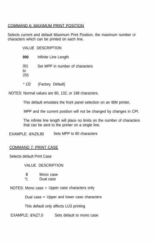
COMMAND 6: MAXIMUM PRINT POSITION
Selects current and default Maximum Print Position, the maximum number Ofcharacters which can be printed on each line.
VALUE DESCRIPTION
000 Infinite Line Length
001to255
Set MPP in number of characters
* 132 (Factory Default)
NOTES: Normal values are 80, 132, or 198 characters.
This default emulates the front panel selection on an IBM printer,
MPP and the current position will not be changed by changes in CPI.
The infinite line length will place no limits on the number of charactersthat can be sent to the printer on a single line.
EXAMPLE: &%Z6,80 Sets MPP to 80 characters
COMMAND 7: PRINT CASE
Selects default Print Case
VALUE DESCRIPTION
0 Mono case*1 Dual case
NOTES: Mono case = Upper case characters only
Dual case = Upper and lower case characters
This default only affects LU3 printing
EXAMPLE: &%Z7,0 Sets default to mono case

COMMAND 8: LU1 LANGUAGE
Selects default LU1 Language.
VALUE DESCRIPTION
* 0103040506070809101112 (same as 11)1314151617 (same as 16)1920212223 (same as 07)24 (same as 09)25 (same as 01)26 (same as 08)27 (same as 10)2829 (same as 06)30 (same as 11)31 (same as 14)32 (same as 14)
English (U.S.) EBCDICAustrian/GermanBelgianBrazilianCanadian (French)Danish/NorwegianDanish/Norwegian (alt.)Finnish/SwedishFinnish/Swedish (alt.)FrenchFrench (alt.)Austrian/German (alt.)International Set 5ItalianJapanese (English)French (alt.)S p a n i s h Spanish (alt.)Spanish SpeakingEnglish (U.K.)NorwegianSwedishEBCDIC (alt.)Norwegian (alt.)Swedish (at.)PortugueseCanadian (Bilingual)French AZERTY (105 character)Swiss GermanSwiss French
NOTES: This command, along with command ‘Z99,0’, changes the default LU1language selection in the non-volatile memory of the interface.
The number of the command value should agree with the languagenumber used in IBM CU configuration sequence number 121.
EXAMPLE: &%Z8,04 Sets LU1 language to Belgian
A-5

COMMAND 9: FONT SELECT (Matrix Printer]
Selects Epson default font when dot matrix printer protocol is selected inCommand 60. This command is not functional when laser printer protocol isselected.
VALUE DESCRIPTION
* 123456789
1011
Draft Print QualityRoman, NLQSans Serif, NLQCourier, NLQ (Font Cartridge Required)Prestige, NLQ (Font Cartridge Required)Script, NLQ (Font Cartridge Required)OCR-B, NLQ (Font Cartridge Required)OCR-A, NLQ (Font Cartridge Required)Orator, NLQ (Font Cartridge Required)Orator-S, NLQ (Font Cartridge Required)Script C, NLQ (Font Cartridge Required)
EXAMPLE: &%Z9,2 Selects near-letter-quality (Roman) as the default
COMMAND 11: PAPER PATH
Selects default paper path for the Page Presentation Media (PPM) command
VALUE
0
DESCRIPTION
1
Ignore the host PPM Command; paper tray selectiondetermined by use of the printer’s front panel.
Tractor Feed or only one paper source used (Ignore the HostPPM)
*2 Cut-Sheet Feeding from primary bin is default
3 Cut-Sheet Feeding from alternate bin is default
4 Envelope Feeder default
5 Manual Sheet Feed default
6 Manual Envelope Feed default
A-6

NOTES: This command defines the default paper source for the PagePresentation Media (PPM) Host command in SCS mode. If the PPMcommand is received from the host, the interface always sends theSCS mode paper source command to the printer unless values 0 or 1are selected. If the printer does not have a secondary paper bin oranenvelope feeder, it ignores the command, but it will be used forCommands 62-64 logic.
If manual sheet feed is specified in the SCS PPM command and nopaper is installed in the manual feed slot, the printer will wait for theoperator to insert perhaps letter head or a special form before printingcontinues.
If this command is placed as the first printable data on the page, (line1, position 1) the specified paper path will take effect immediately. Ifthe command is placed at any other position on the page, the changewill have effect on the next page.
EXAMPLE: &%Z11,5 Selects manual sheet feed default source for paper
COMMAND 12: FORM FEED BEFORE LOCAL SCREEN COPY
Specifies whether a Form Feed is performed before-doing local screen hardcopy.
VALUE DESCRIPTION
* 0 No Form Feed before local screen hard copy
1 Form Feed performed before local screen hard copy
NOTES: This command only affects the local screen copy function, not thehost-initiated local copy printing.
Functions only in non-SCS operations
EXAMPLE: &%Z12,1 Performs a FF before local screen copy
A-7

COMMAND 13: FORM FEED AFTER LOCAL SCREEN COPY
Specifies whether a Form Feed is performed after a local screen hard copy.
VALUE DESCRIPTION
*0 No Form Feed after local screen hard copy
1 Form Feed performed after local screen hard copy
NOTES: To use this function, the RPQ should be:IBM 3268 RPQ SC9508IBM 3287 RPQ MC3750IBM 4214 OPT 20=3
This command only affects the local screen copy, not the host-initiatedlocal copy printing.
Functions only in non-SCS operations
EXAMPLE: &%Z13,1 Perform a FF after local screen copy
COMMAND 14: LU3 PRINT IMAGE (Non-SCS Mode)
Selects Null Line Suppression or True Screen Image in LU3 printing mode
VALUE DESCRIPTION
* 0
1
Null line suppression in Local Copy and non-SCS print
Null line suppression in non-SCS print and true screen imagein Local Copy
2 True screen image in non-SCS print and null line suppressionin Local Copy
3 True screen image in non-SCS print and true screen image inLocal copy
NOTES: To use this function, the RPQ should be:IBM 3268 RPQ SC9505IBM 3287 RPQ SC3741IBM 4214 OPT 18=2
Available only in non-SCS operation
A-8

Command 14, Values 0 and 1 are only functional from CUT terminals.
EXAMPLE: &%Z14,3 Prints true screen image In non-SCS print and localcopy
COMMAND 15: CR at MPP + 1
Sets the printer in accordance with the RPQ installed in the control unit.
VALUE DESCRIPTION
* 0 First print position (PP) of next line
1 First PP of current line
NOTES: To use this function, the RPQ should be:IBM 3268 RPQ SC9501IBM 3287 RPQ S30219IBM 4214 OPT 15=1
Available only in non-SCS operation
EXAMPLE: &%Z15,1 Prints first PP of current line as the next PP when aCR is received at MPP + 1.
COMMAND 16: NL at MPP + 1
Sets the printer in accordance with the RPQ installed in the control unit
VALUE DESCRIPTION
* 0 First PP of current line + 2 lines
1 First PP of next line
NOTES: To use this function, the RPQ should be:IBM 3268 RPQ SC9502IBM 3287 RPQ S30219IBM 4214 OPT 15=1
Available only in non-SCS operation.
EXAMPLE: &%Z16,1 Performs first PP of next line as the next PP when anNL is received at MPP+ 1.
A-9

COMMAND 17: VALID FF FOLLOWED BY DATA
Sets the printer in accordance with the RPQ installed in the control unit
VALUE DESCRIPTION
* 0 Second print position of first line on next form
1 First print position (PP) of first line on next form
NOTES: For the Value 1 selection, the RPQ would be:IBM 3268 RPQ SC9503IBM 3287 RPQ N/AIBM 4214 OPT 16=2
Available only in non-SCS operation
EXAMPLE: &%Z17,1 Performs first PP of first line on next form as the nextPP when a valid FF (positioned anywhere but theend of an IBM print buffer) is received.
COMMAND 18: VALID FF AT END OF PRINT BUFFER
Sets the printer in accordance with the RPQ installed in the control unit
VALUE DESCRIPTION
0 First PP of second line on next form
*1 First PP of first line on next form
NOTES: To use this function, the RPQ should be:IBM 3268 RPQ SC9504IBM 3287 RPQ SC3749IBM 4214 OPT 17=2
Available only in non-SCS operation
EXAMPLE: &%Z18,1 Performs first PP of first line on next form as the nextPP when a valid FF is received at the end of an IBMprint buffer.
A-10

Do not press the form feed or line feed buttons on the front of theprinter. This will cause the host and printer to lose synchronization ofpaper position. This command reduces the need to advance thepaper.
EXAMPLE: &%Z20,1
COMMAND 19: FF VALID LOCATION
Sets the printer in accordance with the RPQ installed in the control unit
VALUE DESCRIPTION
* 0 FF is valid only at the first print position or at positionMPP+1.
1 FF is valid anywhere it occurs.
NOTES: To use this function, the RPQ should be:IBM 3268 RPQ SC9506IBM 3287 RPQ SC3739IBM 4214 OPT 19=1
Available only in non-SCS operation.
EXAMPLE: &%Z19,1 Makes FF valid anywhere it occurs
COMMAND 20: AUTOMATIC FUNCTION AT END OF JOB
Sets the printer in accordance with the RPQ installed in the control unit.
VALUE DESCRIPTION
* 0 NL is automatically executed after the buffer is completed(unless an FF, NL, or CR was last in the buffer).
1 FF is automatically executed after the print buffer iscompleted (unless an FF was last in the buffer).
NOTES: To use this function, the RPQ should be:IBM 3268 RPQ SC9507IBM 3287 RPQ SC3740IBM 4214 OPT 20=2
Available only in non-SCS operation
Sets the printer to issue an FF automatically at theend of the print buffer.
A-11

COMMAND 25: FORM FEED USAGE
Enables a Forms Feed from the host system to be converted to the requirednumber of line feeds (beneficial when forms length is controlled by theinterface).
VALUE DESCRIPTION
0 Pass FF from host to the printer (Laser Printer default)
*1 Count the lines in Command 5 and send multiple line feedsto the printer in place of the host FF.
EXAMPLE: &%Z25,1 Sets the printer to count the lines specified inCommand 5.
COMMAND 26: SUPPRESS EMPTY FORMS
Blank printout pages caused by Form Feed commands that occur at the top ofa form can be suppressed.
VALUE DESCRIPTION
* 0 No, do not suppress empty forms
1 Yes, suppress empty forms
NOTES: If selected, the coax interface ignores Forms Feed commands locatedat the top of form position.
This command affects printing in both DSC and SCS modes. Thisdiffers from the IBM 3287, which suppresses Form Feeds only in DSCmode.
EXAMPLE: &%Z26,1 Sets the interface to suppress empty forms
COMMAND 27: FF AFTER TIME ELAPSE
Sends a Form Feed if unprinted data remains in the print buffer for thespecified coax port time-out interval in Command 51.
A-12

VALUE DESCRIPTION
*0 No extra FF is sent1 Send FF after time out value
NOTES: The time-out value is the same as the time-out used to switch betweenhost and alternate host printer sharing. (See Command 51)
Generally, the host application generates a termination FF, and thereis no need to change this command from the default.
In duplex printing, the last page will be ejected.
EXAMPLE: &%Z27,1 Sends FF after time delay selected by command 51(default = 10 sec.) when unprinted data remains inthe print buffer.
COMMAND 31: TRUNCATE/WRAP SELECT
The user can select whether the interface truncates or wraps the text if themaximum print position is exceeded.
VALUE DESCRIPTION
* 0 Allow text to print on next line when maximum print positionis exceeded.
1 Truncate text beyond the maximum print position
EXAMPLE: &%Z31,1 Causes text which exceeds the maximum printposition to be lost.
COMMAND 32: PAPER SIZE (LASER)
Specifies the paper size used for printing
VALUE DESCRIPTION
*0 Selects 8 1/2" X 11" letter paper
1 Selects 210mm X 297mm (8.27’ X 11.69”) A-4 paper
2 Selects 8 1/2” X 14” legal paper
EXAMPLE: &%Z32,1 The interface tells the printer to use A-4 paper.
A-13

COMMAND 34: INTERVENTION REQUIRED (IR) TIME OUT
Sets the time interval before an intervention required signal is sent to the hostafter a printer error occurs.
VALUE DESCRIPTION
000 Never send an IR
001to255
Send IR after the VALUE times 5 seconds after printer erroroccurs.
* 120 Default, send IR after ten minutes.
EXAMPLE: &%Z34,036 Sets IR time interval to 3 minutes
COMMAND 35: PROGRAM ATTENTION (PA) RESPONSE
The IBM host software can send a program attention (PA) request to theprinter, causing the printer to stop printing until a PA1 or PA2 response fromthe printer is sent to the host software. The interface can be set to eitherautomatically return a PA1 response upon receiving a PA request or stop andwait (with red LED on) until the operator presses one of the two push buttonson the interface card.
VALUE DESCRIPTION
*0 Printer stops and waits for operator to press a PA1 or PA2push button before sending the PA response to the host.
1 Interface automatically responds with a PA1 if a PA request isreceived from the host.
NOTE: This can be used to enable an operator to install special forms,colored paper, legal paper, etc. in the printer before the PA pushbutton is pressed.
EXAMPLE: &%,Z35,1 Printer automatically responds with a PA1 response.
A-14

COMMAND 36: SUPPRESS IBM CONTROL CODES
This function is used to select suppression of all or some IBM control codessent from the host system.
VALUE DESCRIPTION
*0 Obey all IBM control codes
1 Suppress all IBM control codes
2 Suppress only LPI and CPI control codes
3 Suppress only CPI control codes
4 Suppress only LPI control codes
5 Suppress print quality specified in the PPM command.
NOTES: If this command is set to 1, documents will have to be formatted bysending transparent control codes to the printer using Command-Pass-Thru or SCS mode transparent data
If this command is set to 2, the SCS pitch (CPI) and line density (LPI)commands are suppressed (Not sent to the printer).
EXAMPLE: &%Z36,2 No LPI or CPI commands are sent to the printer.The printer prints using the user specified selections.
COMMAND 37: VERTICAL CHANNEL SELECT (VCS)
Specifies vertical channel select VCS) emulation.
VALUE DESCRIPTION
0 3287 VCS emulation
*1 3268/4214/4224 VCS emulation
EXAMPLE: &%Z37,0 Selects 3287 VCS emulation
A-15

COMMAND 38: TRUE LPI SPACING (LASER)
Because laser printers have a non-printable border around the edge of single-sheet pages, 6-LPI and 8-LPI spacing is compressed slightly to enable 66 linesand 88 lines to be printed on 11-inch long paper. This can occasionally causea problem, especially with preprinted forms. Command 38 enables a user tooverride the normal laser printer LPI compression.
VALUE DESCRlPTlON
*0 Compress the vertical LPI spacing
1 Print using true 6 and 8 LPI spacing
NOTE: If true LPI is selected, the user needs to adjust the document formatsto allow for the reduced number of lines that can be printed per page;otherwise, blank pages are ejected by the laser printer because ofblank line feeds that do not fit on the reduced page size. (Refer to thelaser printer’s operator’s manual.)
EXAMPLE: &%Z38,1 Specifies that vertical spacing prints using true 6 and8 LPI. For an 11" page, 63 lines at 6 LPI or 84 linesat 8 LPI are the maximum that fit on a page
COMMAND 40: ALTERNATE DELIMITER CHARACTERS
Specifies two characters in addition to &% which can be used for the ‘delimiter’characters for Command-Pass-Thru and Host Download Commands.
VALUE DESCRIPTION
0000 Deletes previously selected alternate characters
XXYY XX is the ASCII HEXADECIMAL value of the first characterand YY is the ASCII HEX value of the second character.
EXAMPLE: &%Z40,253F Specifies the %? characters as the alternate‘delimiter’ characters, % ASCII hex value is 25 and ?ASCII hex value is 3F in this example.
A-16

COMMAND 41: COMMAND ID CHARACTER
Specifies the character which can be used for the command identifier (in placeof "Z" which follows the ‘Lead In’ characters.
VALUE DESCRIPTION
*5A Makes Z the command character.
ZZ ZZ is the ASCII HEX value of the command ID character.
NOTE: The character selected must not be 0 through 9 or A through F (validhex values), or L, P, U.
EXAMPLE: &%Z41,59 Specifies ‘Y’ as the alternate command ID character
COMMAND 42: START AND STOP BUFFER HEX DUMP
Upon receipt of a start command, the coax interface, starting with the nextbuffer received, sends all host data directly to the printer as hexadecimalprinting until a stop command is received or the printer is powered off.
VALUE DESCRIPTION
* 0 No Action Taken
1 Start Buffer Hex Dump
2 Stop Buffer Hex Dump
NOTES: This is an alternative to pressing both push buttons on the interfacecard and holding them for more than 2 seconds to activate Buffer HexDump.
This command enables the user to print only the section of thedocument that is in question in Buffer Hex Dump Format. But, hexprinting starts with the buffer following the start command and stopswith the buffer following the stop command.
EXAMPLES: &%Z42,1 Starts Buffer Hex Dump Printing&%Z42,2 Stops Buffer Hex Dump Printing
A-17

COMMAND 45: SCS TRN TRANSLATE
Specifies how transparent data sent using SCS code 35 is handled.
VALUE DESCRIPTION
0 Binary Transparent
* 1 Emulate IBM 3287 Printer
NOTES: Value 1 causes valid graphic characters to be printed normally (i.e.,converted from EBCDIC to ASCII), control codes and invalid graphicsto be printed as hyphens, and normal page formatting is maintained.
Value 0 causes the 8 bit binary codes to be sent directly to the printerjust as they are received from the host.
SCS code 36 functions the same as code 35.
EXAMPLE: &%Z45,0 All SCS Code 35 data is sent to the printer as binarycodes without translation.
COMMAND 50: PARALLEL PORT TIME OUT
Selects the time interval that the interface waits for receipt of additional datafrom the alternate (PC) host before automatically switching to check for datafrom the coax host.
VALUE DESCRIPTION
01to60
Time interval in number of seconds
*5 Factory Default is 5 seconds
NOTES: The interface sends a reset command to the printer and restores thecoax host defined format commands (i.e. LPI, CPI, MPL, MPP) prior toprinting data from the coax host after having printed data from theshared parallel port.
A-18

Because the printer is being shared between the parallel port and the3270 host, careful attention should be paid to setting up the PC sothat jobs are not automatically terminated because the printer is. busy.
This problem may be helped by setting the PC timer “off by writing"mode 1pt1:,,p" (in case of an LPT1 printer) in DOS.
Use of the DOS PRINT command or a spooling program for the PC isrecommended.
If your printer supports intelligent Emulation Switching (IES), makesure your printer’s IES timeout period is less than the command 50timeout setting.
EXAMPLE: &%Z50,10 Sets the time interval to 10 seconds
COMMAND 51: COAX PORT TIME OUT
Selects the time interval that the interface waits for receipt of additional datafrom the coax host before automatically switching to check for data from thealternate (PC) host.
VALUE DESCRIPTION
00 The interface never checks for parallel port data (parallelshared port is disabled).
01to60
Time interval in number of seconds
*10 Factory Default is 10 seconds
NOTE: The alternate (PC) host is responsible for sending any needed formatcommands required by the printer prior to sending printable data.
If your printer supports Intelligent Emulation Switching (IES), makesure your printer’s IES timeout period is less than the command 51timeout setting.
EXAMPLE: &%Z51,05 Sets the time interval to 5 seconds
A-19

COMMAND 55: CUSTOM USER STRINGS
Allows a coax user to define up to six custom user strings, of up to 25 byteseach, which are stored in the memory of the interface card and sent to theprinter whenever the “two-letter delimiter, letter U, and number of the string’appears in the text of the document, i.e. &%U3.
VALUE DESCRIPTION
0 Following the value number, insert a parenthesis, followed byto the ASCII hex bytes included in the user string, and then a5 parenthesis to end.
NOTES: To aid in readability, a single space is allowed between hex bytes butis not included in the string.
The strings could specify a special font selection command or othercustom command to be sent directly to the printer.
This command, if placed as the first printable data at the top of thepage (position 1, line 1), will be sent to the printer prior to the data.
To change a custom user string, simply input the new custom userstring values. The entire old string is automatically erased.
To delete a custom user string from the NV memory, simply putnothing between the parentheses.
EXAMPLES: &%Z55,3(1 B01) Defines the &%U3 custom user string tosend an "ESC and SOH" (1B and 01 hex) tothe printer. This is the Epson Double-Width, One Line, ON command.
&%Z55,4(OF) Defines the &%U4 custom command tosend "SI" (shift in, OF hex) to the printerwherever the &%U4 command appears inthe text. This turns ON the Epsoncondensed printing.
&%Z55,5(12) Defines the &%U5 custom command tosend "DC2" (Device Control 2, 12 hex) tothe printer. This is the Epson condensedprinting OFF command.
&%Z55,1( ) Deletes from NV memory any hex stringthat had been previously defined for the&%U1 custom command.
A-20

COMMAND 56: SHARED PORT INlTlALlZATlON STRING
Allows the user to define an initialization string of up to 25 bytes which arestored in the memory of the interface card and sent to the printer at thebeginning of any printing received from the alternate shared port.
VALUE DESCRlPTlON
1 Following the value number, insert a parenthesis, followed bythe hex bytes included in the command string, and then aparenthesis to end.
NOTES: To aid in readability, a single space is allowed between hex bytes butis not included in the string.
The string could specify a special font selection command or othercustom command to be sent directly to the printer prior to the datathat is received from the parallel shared port.
To change the initialization string simply input the new commandvalues. The entire old string is automatically erased.
To delete the initialization string from the NV memory, simply putnothing between the parentheses.
EXAMPLE: &%Z56,1( ) Deletes from NV memory any hex string that hadbeen previously defined for the parallel portinitialization string.
COMMAND 57: COAX PORT lNlTIALlZATlON STRING
Allows the user to define an initialization string of up to 25 bytes. This string isstored in the memory of the interface card and is sent to initialize the printer forcoax port printing after printing from the shared parallel port has occurred.The interface also, after the initialization string, sends commands to restore thedefault or host defined page format parameters prior to coax port printing.
VALUE DESCRIPTION
1 Following the value number, insert a parenthesis, followed bythe hex bytes included in the command string, and then aparenthesis to end.
A-21

NOTES: To aid in readability, a single space is allowed between hex bytes butis not included in the string.
The coax port initialization string is only sent to the printer when youturn the printer on and after printing by the shared parallel port hasoccurred. Host SCS commands and download commands havepriority over the initialization string instructions.
To change the initialization string simply input the new commandvalues. The entire old string is automatically erased.
To delete the initialization string from the NV memory, simply putnothing between the parentheses.
EXAMPLE: &%Z57,1( ) Deletes from NV memory any hex string that hadbeen previously defined for the coax portinitialization string
COMMAND 60: ASCII PRINTER PROTOCOL
Specifies the type of ASCII printer protocol instructions that the interface willuse when converting from the 3270 coax cable commands. Most EpsonESC/P printers will automatically on power up set this command to agree withthe type of printer In which the interface is installed. If your printer is a laserprinter, this command is invalid.
VALUE DESCRlPTlON
* 1 Epson ESC/P dot matrix protocol2 HP LaserJet PCL4 laser protocol
NOTES: HP LaserJet protocol automatically uses the Roman 8 character setand Epson ESC/P requires that the Code Page 850 character set beselected by the user through front panel selections or DIP switchselections.
The HP LaserJet laser protocol supports the ability to specify cartridgefonts by simply including a font ID Command in the document.
A change in this command is not active until it is saved to NV memoryusing an ‘&%Z99,0’ and the unit is turned off and then on again.
When laser protocol is selected, the default for Command 25 changesto the ‘form feed’ option.
EXAMPLE: &%Z60,2 Selects use of the HP LaserJet PCL4 laser protocol
A-22

EXAMPLE: &%Z61 ,1 APO is not active.
COMMAND 61: AUTOMATlC PRINT ORIENTATION (APO) (LASER)
Laser printers automatically control page orientation if the user decides toactivate auto print orientation (APO). Refer to the page orientation logic chartin the computer output reduction section of the manual.
VALUE DESCRlPTlON
* 0 Auto Print Orientation (APO) is ACTIVE. The pagedimensions of a document are checked to determine if thedata should be printed in landscape because the width isgreater than the length.
1 Auto Print Orientation (APO) is NOT ACTIVE. Print orientationis controlled by the orientation selections specified inCommands 62, 63, and 64.
NOTE: APO active is the recommended selection.
A user can manipulate the page dimensions using SCS commands tocontrol the orientation of the printing as long as the page size requiredis 8 1/2" X 11” or smaller.
COMMAND 62: PRIMARY PAPER TRAY ORIENTATION (LASER)
The SCS (LU1) PPM command, which specifies the source for the paper,assigns a printing orientation to the primary paper tray. Refer to the pageorientation logic chart in the computer output reduction section of the manual.This command duplicates the IBM 3812 and 4028 printer’s feature with theadditional selection of option 3 below.
VALUE DESCRlPTlON
*0 Computer Output Reduction (COR) Mode is active whenpaper is specified to be selected from the primary tray.
1 PORTRAIT orientation will occur using the active font whenthe primary tray is specified.
2 LANDSCAPE orientation printing occurs using the active fontwhen the primary tray is specified.
A-23

3 User Defined mode; documents are printed using the fontsand orientation that the user specifies through use of the &%font ID commands.
EXAMPLE: &%Z62,3 Specifies that the document is printed as formattedwhen the primary paper tray is specified as thepaper source.
COMMAND 63: ALTERNATE PAPER TRAY ORIENTATION (LASER)
This command functions identically to Command 62 except it controls theorientation for printing that specifies (SCS,LU1) the alternate tray for the papersource.
Values are the same as Command 62 except substitute ‘alternate tray’ for‘primary tray’ in the descriptions.
NOTES: Even if the printer does not have an alternate paper tray and defaultsto the primary tray, if the SCS (LUl) host specifies the alternate tray,the interface prints the document in accordance with the selection inCommand 63.
The value 3 is an excellent choice when COR is not required, sincethe user can decide the fonts and orientation he desires by using &%font ID commands.
EXAMPLE: &%Z63,2 Specifies that landscape orientation will be used forall printing in which the SCS (LU1) PPM codespecifies the alternate paper tray be used.
COMMAND 64: MANUAL FEED TRAY ORIENTATION (LASER)
This command functions identically to Command 62 except it controls theorientation for printing when the PPM Command specifies the manual feed trayfar the paper source.
Values are the same as Command 62 except substitute ‘manual feed tray’ inplace of ‘primary tray’ in the descriptions.
NOTE: A laser printer, upon receipt of the manual feed tray command, doesnot proceed with printing until paper is placed into the manual feedslot. This allows a user to insert special forms, letter head, or coloredpaper into the manual feed slot.

EXAMPLE: &%Z64,1 Specifies all printing performed using paper from themanual feed slot be printed in portrait orientation.
COMMAND 65: CHARACTER SET SELECTION
Enables the user to make a special selection of the ASCII character set that isused in the conversion from EBCDIC (SCS/LU1) or DSC (LU3) to ASCII. Thisis the character set that the printer uses in printing. It must be selected at theprinter by using the front panel or dip switches of the printer. Changing theprotocol selection in Command 60 automatically changes the character set asrequired. However, Command 65 can override the automatic selection.
VALUE DESCRIPTION
1 Roman 8 character set
* 2 Code Page 850 character set
NOTES: The character set substitutions defined in Commands 70 and 71 mustbe adjusted if the ASCII character set is changed. All previouslydefined substitutions are lost from NV memory when the character setselection is changed.
Refer to the character set summary tables at the end of the self test toconfirm which ASCII character is printed for each of the 3270 hexcodes. Both the EBCDIC and DSC tables are provided.
EXAMPLE: &%Z65,2 Selects the Code Page 850 character set
COMMAND 70: OVERWRITE EBCDIC (SCS/LU1) TRANSLATION TABLE
Custom substitutions defined by this command and stored in NV memory arewritten into the EBCDIC (SCS/LU1)-to-ASCII translation table.
VALUE DESCRIPTION
xx The hex location in the EBCDIC table that sends the followingASCII hex sequence.
YY The ASCII hex sequence that is overwritten in the EBCDICtranslation table.
A-25

NOTES: Previously stored substitutions are automatically changed to the newselection when the same hex location is specified in the EBCDICtable.
Previously stored substitutions are cancelled if an ASCII hex sequenceof 00 is specified.
Command ‘Z99,0’ must be used to store the substitutions in NVMemory for them to be effective when the printer is next turned on.
The active EBCDIC (SCS/LU1) translation table prints out at the end ofthe interface self-test summary.
EXAMPLE: &%Z70,7B,40/Z99,0 Overwrites the ASCII hex output for theEBCDIC 7B (a # symbol) to send a 40ASCII hex which will print a @ symbolinstead. The command is followed by acommand ‘Z99,0 which stores the activesetup selections in non-volatile memory.
COMMAND 71: OVERWRITE DSC (LU3) TRANSLATION TABLE
Custom substitutions defined by this command, and stored in the NV memory,are overwritten into the DSC (LU3) to ASCII translation table.
NOTES: This command functions identically to Command 70 except that thesubstitutions are applicable to the DSC (LU3) translation table. Referto the Command 70 instructions.
The active DSC (LU3) translation table prints out at the end of theinterface self-test summary.
COMMAND 98: RESTORE DEFAULTS CR PRINT CONFIGURATION
Restores the factory default configuration selections, prints out a copy of theactive configuration selections, or restores the non volatile memory (NV)selections to the active configuration status.

VALUE DESCRIPTION
0 Restores the factory defaults to the NV memory of theinterface.
1 Prints out the active setup selections for review by the user.
2 Restores the setup selections stored in the NV memory toactive status of the interface.
NOTES: The active setup selections are the same as the NV memoryselections if no host download commands have been sent to theprinter since it was turned on.
Value 2 is a quick way, after having printed a document using specialsetup selections, to return the interface to the normal selections. Puta &%Z98,2 at the end of the special document to restore the standardsetup parameters for the next coax user of the printer.
The active setup and NV memory setup selections are the same aftera command ‘Z99,0 or a Command ‘Z98,2’ is sent to the printer.
EXAMPLE: &%Z98,1 Prints out the active-setup selections for review bythe user.
COMMAND 99: STORE CONFIGURATION IN NV MEMORY
Send this command after all desired host download configuration commandshave been sent to the interface. It stores the active setup in the NV memory ofthe interface so that it will be in effect whenever you turn on the printer.Otherwise, active configuration commands are lost when the printer is turnedOff.
VALUE DESCRIPTION
0 To complete the command format, the value 0 must be used.
NOTES: Only host download selections which have been followed by aCommand ‘Z99,0’ will be stored in NV memory and restored to theactive setup when the printer is turned on.
Only use Command ‘Z99,0’ when the host download selection needsto be permanently stored in the memory of the coax interface.
EXAMPLE: &%Z99,0 Stores the currently active setup selections in the NVmemory of the interface.
A-27

APPENDIX B: PUSH BUTTON SETUP
Push button (Yes / No) setup provides an alternate method for a user to select thebasic configuration selections for the printer emulation. Selections can also bechanged by the Host Download Configuration Commands as specified inAppendix A which has more detailed information on the selections.
Push button setup is selected by performing a self test and at the end of the selftest print out the last line of printing will have the question: ‘Do you want to dopush button set up?’ Press the PA1 push button to answer the question"Yes".Press the PA2 push button to answer the question “No’, or simply turn off theprinter to discontinue push button setup.
NOTE: For reference, your ‘Yes’ or “No’ response is printedbefore the next option statement is printed. Someprinters may require you to line feed the paper to aposition where the printed text can be read. On alaser printer, it is necessary to form feed a page toread the printed output.
A detailed example of the Push Button Setup printout is as follows:
1920 = Logical Buffer Size Do you want this changed? (Yes I No) Yes
2560= Logical Buffer SizeDo you want this changed? (Yes / No) Yes
3564= Logical Buffer SizeDo you want this changed? (Yes / No) Yes
3440 = Logical Buffer SizeDo you want this changed? (Yes / No) Yes
960 = Logical Buffer SizeDo you want this changed? (Yes / No) Yes
1920= Logical Buffer . ..(Sequence repeats until a ‘No’ response is given)
A “Yes’ response causes the next selection in the option group to be substitutedinto the printed statement with a similar Yes / No response requested. When the‘No’ button is pushed, the current configuration selection remains and theselection jumps to the next configuration setup option group. The selections are
B-l

grouped together with periodic opportunities to end push button setup providedat the end of each group.
Following is the summary list of the push button setup option groups that areused to select the basic configuration. The underlined segment of each statementis the portion that changes.
*Epson ESC/P dot matrix protocol activeDo you want this changed? (Yes/ No)Alternate Selections:* HP Laserjet PCL
(Reference Command 60)
* Epson ESC/P dot matrix
*1920= Logical Buffer Size (Reference Command 1)Do you want this changed? (Yes / No)Alternate Selections:* 2560*3564* 3440* 960* 1920
*6 = Default LPIDo you want this changed? (Yes / No)Alternate Selections:* 8* 3* 4* 6
(Reference Command 2)
*10 = Default CPIDo you want this changed? (Yes/No)Alternate Selections:* 12* 15* 16.7* 10
(Reference Command 3)
B-2

*Single (6 or 8 LPI) = Default SpacingDo you want this changed? (Yes I No)Alternate Selections:
(Reference Command 4)
*Double (3 or 4 LPI)* Single (6 or 8 LPI)
* 66 = MPL (Reference Command 5)Do you want this changed? (Yes / No)Alternate Selections:* 72* 84* 66
*132 = Default MPP (Reference Command 6)Do you want this changed? (Yes / No)Alternate Selections:* 198* 255* Infinite* 80* 132
*Dual Case = Default Print CaseDo you want this changed? (Yes / No)Alternate Selections:* Mono* Dual
(Reference Command 7)
*English (U.S.) = Default Language (Reference Command 8)Do you want this changed? (Yes I No)Alternate Selections:* Austrian / German* Belgian* Brazilian* Canadian / French* Danish / Norwegian* Danish / Norwegian (alt)* Finnish / Swedish* Finnish / Swedish (alt)
B-3

* French* Austrian / German (alt)* International* Italian* Japanese (English)* Spanish* Span&h (alt)* Spanish Speaking* English (U.K.)* Portuguese* English (U.S.)
Do you want to END? (Yes / No)NO response continues with following set-up selections.YES response prints: Save current settings? (Yes / No)YES response prints: Selections stored, turn off unit.
*No FF before local screen hard copyDo you want this changed? (Yes / No)Alternate Selections:* FF
(Reference Command 12)
* No FF
*No FF after local screen hard copyDo you want this changed? (Yes / No)Alternate Selections:* FF* No FF
(Reference Command 13)
*LU3 and Local COPY Null line suppressionDo you want this changed? (Yes I No)Alternate Selections: * LU3* Local copy* NO
(Reference Command 14)
* LU3 and Local Copy
B-4

*Next Line first PP, for CR at MPP +Do you want this changed?Alternate Selections:* Current line* Next line
1(Yes / No)
(Reference Command 15)
*Current Line + 2 is next PP for NL at MPP + 1Do you want this changed? (Yes / No)Alternate Selections:* Next line
(Reference Command 16)
* Current line + 2
* 2nd PP of line 1 on next form, for FFDo you want this changed? (Yes / No)Alternate Selections:* 1st PP* 2nd PP
(Reference Command 17)
*Line 1 first PP of next form, for valid FF at EOBDo you want this changed? (Yes / No) Alternate Selections:* Line 2* Line 1
(Reference Command 18)
*FF valid at 1st PP or MPP + 1Do you want this changed? (Yes / No)Alternate Selections:* FF valid anywhere
(Reference Command 19)
* FF valid at 1st PP or MPP + 1
* NL will be added at EOB if not presentDo you want this changed? (Yes / No)Alternate Selections:* FF* NL
(Reference Command 20)
B-5

Do you wish to end? (Yes / No)NO response continues with following set up selections.YES response prints: Save current settings? (Yes / No)YES response prints: Selections stored, turn off unit.
*Multi LF’s used to eject forms (Reference Command 25)Do you want this changed? (Yes / No)Alternate Selections:* FF* Multi LF
*Suppress empty forms (Reference Command 26)Do you want this changed? (Yes / No)Alternate Selections:* Do not suppress empty forms.* suppress empty forms.
*Do Not FF if data in the printer after time outDo you want this changed? (Yes / No)Alternate Selections:
(Reference Command 27)
* Do* Do not send
*Wrap text beyond MPP (Reference Command 31)Do you want this changed? (Yes I No)Alternate Selections:* Truncate* Wrap
B-6

*10 min. = IR timeoutDo you want this changed? (Yes I No)Alternate Selections:* 20 min* Disabled* 5 sec* 30 sec* 60 sec* 3 min* 10 min
(Reference Command 34)
*Manual PA1/2 responseDo you want this changed? (Yes / No)Alternate Selections:* Auto PA1* Manual PA1/2
(Reference Command 35)
*No IBM control codes suppressed (Reference Command 36)Do you want this changed? (Yes / No)Alternate Selections:* CPI* LPI* CPI/LPI* Print quality* All* No
* 3268/4224 VCS emulation (Reference Command 37)Do you want this changed? (Yes / No)Alternate Selections:* 3287* 3268/4224
*Compressed LPI spacingDo you want this changed? (Yes / No)Alternate Selections:* True* Compressed (Normal)
(Reference Command 38)
B-7

*3287 emulation of SCS command 35 (Reference Command 45)Do you want this changed? (Yes / No)Alternate Selections:* Binary transparent data* 3287
*5 Seconds for Parallel Port time outDo you want this changed? (Yes / No)Alternate Selections:* 10* 20* 30* 60* 5
(Reference Command 50)
*10 Seconds for Coax Port time outGo you want this changed? (Yes / No)Alternate Selections:* 20* 30* 60* 5* 10
(Reference Command 51)
Do you want to END? (Yes / No)NO response continues,with following set-up selections.YES response prints: Save current settings? (Yes / No)YES response prints: Selections stored, turn off unit.
*APO activeDo you want this changed? (Yes / No)Alternate Selections:l APO notl APO
(Reference Command 61)
B-8

*COR Is primary paper tray orientationDo you want this changed? (Yes / No)Alternate Selections:* Portrait* landscape
(Reference Command 62)
* User Defined* COR
* COR is secondary paper tray orientationDo you want this changed? (Yes / No)Alternate Selections:* Portrait* Landscape* User Define* COR
(Reference Command 63)
*COR is manual paper tray orientation (Reference Command 64).Do you want this changed? (Yes / No)Alternate Selections:* Portrait* Landscape* User Define* COR
*Code Page 850 is character setDo you want this changed? (Yes / No)Alternate Selections:* Roman 8* Code Page 850
(Reference Command 65)
SAVE CURRENT SETTINGS? (Yes / No)YES Response Prints: Selections stored, turn off unit.NO Response returns to the beginning.
B-9

APPENDIX C

APPENDIX C

APPENDIX C

APPENDIX c

APPENDIX C
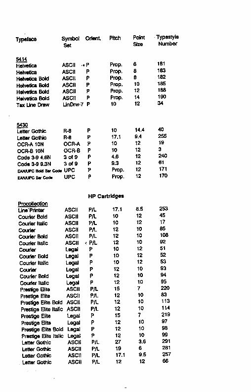


EPSON’