xpanel designer users - anaheim automation
TRANSCRIPT

© 2006 KDT SYSTEMS Co.Ltd. All Rights Reserved.
CIMON-Xpanel
Note:To change the product logo for your own print manual orPDF, click "Tools > Manual Designer" and modify theprint manual template.

Title page 1Use this page to introduce the product
by KDT SYSTEMS Co.,LTD.
This is "Title Page 1" - you may use this page tointroduce your product, show title, author, copyright,company logos, etc.
This page intentionally starts on an odd page, so that itis on the right half of an open book from the readerspoint of view. This is the reason why the previous pagewas blank (the previous page is the back side of thecover)

All rights reserved. No parts of this work may be reproduced in any form or by any means - graphic, electronic,or mechanical, including photocopying, recording, taping, or information storage and retrieval systems -without the written permission of the publisher.
Products that are referred to in this document may be either trademarks and/or registered trademarks of therespective owners. The publisher and the author make no claim to these trademarks.
While every precaution has been taken in the preparation of this document, the publisher and the authorassume no responsibility for errors or omissions, or for damages resulting from the use of informationcontained in this document or from the use of programs and source code that may accompany it. In no eventshall the publisher and the author be liable for any loss of profit or any other commercial damage caused oralleged to have been caused directly or indirectly by this document.
Printed: 8월 2012 in (whereever you are located)
CIMON-Xpanel
© 2006 KDT SYSTEMS Co.Ltd. All Rights Reserved.
PublisherSpecial thanks to:
All the people who contributed to this document, to mum anddad and grandpa, to my sisters and brothers and mothers inlaw, to our secretary Kathrin, to the graphic artist who createdthis great product logo on the cover page (sorry, don'tremember your name at the moment but you did a great work),to the pizza service down the street (your daily Capricciosassaved our lives), to the copy shop where this document will beduplicated, and and and...
Last not least, we want to thank EC Software who wrote thisgreat help tool called HELP & MANUAL which printed thisdocument.
Managing Editor
Technical Editors
Cover Designer
...enter name...
...enter name...
...enter name...
...enter name...
...enter name...
Production
...enter name...
Team Coordinator
...enter name...

CIMON-Xpanel4
© 2006 KDT SYSTEMS Co.Ltd. All Rights Reserved.
Table of Contents
Foreword 11
Part I Welcome to CIMON-Xpanel 13
Part II XPanelDesigner Update : V2.23 16
Part III Ethernet Loader 24
................................................................................................................................... 241 How to use Ethernet Loader
................................................................................................................................... 262 How to update Ethernet Loader
.......................................................................................................................................................... 26V2.10
Part IV Installation Guide 32
................................................................................................................................... 321 Essential Safaty Precautions
................................................................................................................................... 342 General Safety Precautions
................................................................................................................................... 363 Package Contents
................................................................................................................................... 374 Specification
................................................................................................................................... 385 Installation / Dimensions
................................................................................................................................... 416 Interfaces
................................................................................................................................... 447 Wiring
................................................................................................................................... 458 Developing Environment Setup
Part V SYSTEM Overview 53
................................................................................................................................... 531 Peripherals
................................................................................................................................... 542 Network
................................................................................................................................... 553 Xpanel Designer
................................................................................................................................... 564 Xpanel Unit
Part VI Configuration Tools 60
................................................................................................................................... 601 System Log : System Activity Log
................................................................................................................................... 612 Comm. Monitor : Communication Frame Monitor
................................................................................................................................... 623 Comm. Config : Communication Port Configruation
................................................................................................................................... 664 Misc. Config : Miscellaneous Configurations
................................................................................................................................... 675 Touch Calibrate : Touch Panel Calibration
................................................................................................................................... 686 Screen Capture : Make a Screen Snapshot
................................................................................................................................... 687 Date/Time : Adjust the System Clock
................................................................................................................................... 698 SW Keyboard : Pops-Up the Software Keyboard
................................................................................................................................... 699 Printer : Printer Setup
................................................................................................................................... 7310 System Shutdown

5Contents
5
© 2006 KDT SYSTEMS Co.Ltd. All Rights Reserved.
................................................................................................................................... 7411 Exit
Part VII Xpanel Designer 76
................................................................................................................................... 761 How to download project data
................................................................................................................................... 862 Xpanel Designer Installing and Running
................................................................................................................................... 873 Xpanel Designer menu
................................................................................................................................... 914 Project setup and download
Part VIII TAG Database 97
................................................................................................................................... 971 Overview
................................................................................................................................... 982 Database Window
................................................................................................................................... 993 How to use Database
................................................................................................................................... 1034 Group TAG
................................................................................................................................... 1045 Digital TAG
................................................................................................................................... 1046 Analog TAG
................................................................................................................................... 1077 String TAG
................................................................................................................................... 1088 Database edit using EXCEL
Part IX I/O Device 113
................................................................................................................................... 1131 I/O Device Basic
................................................................................................................................... 1142 I/O Device Ethernet
................................................................................................................................... 1173 I/O Device Serial
Part X Alarm 122
................................................................................................................................... 1221 Alarm Group
................................................................................................................................... 1232 Alarm Configuration
................................................................................................................................... 1283 Alarm Summary
Part XI Graphic Page Editor 134
................................................................................................................................... 1351 Page Properties
................................................................................................................................... 1392 Frame Editor
................................................................................................................................... 1433 Library
.......................................................................................................................................................... 144Wizard Object
.......................................................................................................................................................... 155User Library
................................................................................................................................... 1584 Object Properties
.......................................................................................................................................................... 160Style
.......................................................................................................................................................... 161Visible
.......................................................................................................................................................... 162Blink
.......................................................................................................................................................... 162V-Size
.......................................................................................................................................................... 163H-Size
.......................................................................................................................................................... 164V-Move
.......................................................................................................................................................... 165H-Move
.......................................................................................................................................................... 167Color

CIMON-Xpanel6
© 2006 KDT SYSTEMS Co.Ltd. All Rights Reserved.
.......................................................................................................................................................... 167Rotate
.......................................................................................................................................................... 169Touch
.......................................................................................................................................................... 171EntryData
.......................................................................................................................................................... 172Switch/Lamp
Part XII Keypad Page 185
................................................................................................................................... 1851 Make Keypad Page
Part XIII Key Input Window 189
................................................................................................................................... 1891 Key Input Setting
Part XIV Data Logging 193
................................................................................................................................... 1931 Data Logging Configuration
................................................................................................................................... 1972 Using Data Logging
Part XV Data Bridge 200
................................................................................................................................... 2001 Edit Data Bridge Model
Part XVI Modbus Slave 206
................................................................................................................................... 2071 Modbus Slave Setting
Part XVII Recipe 212
................................................................................................................................... 2131 Model Configuration
................................................................................................................................... 2172 Recipe Operator Interface
Part XVIII System Memory 221
................................................................................................................................... 2211 Using System Memory Tag
................................................................................................................................... 2232 Example of using system memory about opened page log.
................................................................................................................................... 2303 Editing recipe data using system memory
Part XIX Trend 238
................................................................................................................................... 2381 YT Trend
................................................................................................................................... 2452 Scope Trend
................................................................................................................................... 2513 SPC Trend
................................................................................................................................... 2584 ST Trend
................................................................................................................................... 2655 LOG Trend
................................................................................................................................... 2716 XY Trend
Part XX String Editor 280
................................................................................................................................... 2801 String Construction
Part XXI Using Multiple Language 287
................................................................................................................................... 2871 Multiple Language setup

7Contents
7
© 2006 KDT SYSTEMS Co.Ltd. All Rights Reserved.
................................................................................................................................... 2902 Multiple language string display
................................................................................................................................... 2923 Using Multiple Language (Change the displayed language by
using multiple language table)
Part XXII Network Data Server 299
................................................................................................................................... 2991 Data Definition in Xpanel
................................................................................................................................... 3002 The Configuration of CIMON SCADA
Part XXIII Security 306
................................................................................................................................... 3061 User Registration
................................................................................................................................... 3082 Access Privilege
................................................................................................................................... 3103 User LogOn / LogOff
Part XXIV Script 313
................................................................................................................................... 3131 Structure of Program
................................................................................................................................... 3172 Operator
................................................................................................................................... 3193 Scripts for command and condition
................................................................................................................................... 3214 Statements
.......................................................................................................................................................... 322IF-ELSE Statement
.......................................................................................................................................................... 322WHILE/DO-WHILE Statement
.......................................................................................................................................................... 323FOR Statement
.......................................................................................................................................................... 323SWITCH-CASE Statement
.......................................................................................................................................................... 324GOTO Statement
.......................................................................................................................................................... 324CONTINUE Keyword
.......................................................................................................................................................... 325RETURN Keyword
.......................................................................................................................................................... 326RUNSCRIPT Keyword
................................................................................................................................... 3265 Internal Functions
.......................................................................................................................................................... 331PageOpen(S1)
.......................................................................................................................................................... 331FrameOpen(S1)
.......................................................................................................................................................... 332StringTable(R1, R2)
.......................................................................................................................................................... 332GetTime(R1)
.......................................................................................................................................................... 333TimeStr(R1, S2)
.......................................................................................................................................................... 333RunApp(S1, S2)
.......................................................................................................................................................... 334MakeCsv(S1, R2)
.......................................................................................................................................................... 335MakeCsvUsb(S1, R2)
.......................................................................................................................................................... 335MakeLogCsv(S1,R2,R3)
.......................................................................................................................................................... 336DataLog(S1, R2)
.......................................................................................................................................................... 337RcpDownload(R1)
.......................................................................................................................................................... 337RcpUpload(R1)
.......................................................................................................................................................... 338RcpStop(S1)
.......................................................................................................................................................... 338RcpFileStore(S1, R2)
.......................................................................................................................................................... 339RcpFileRead(S1, R2)
.......................................................................................................................................................... 339RcpMemDown(S1)
.......................................................................................................................................................... 339RcpMemUp(S1)
.......................................................................................................................................................... 340RcpCsvRd(S1, S2, R3)
.......................................................................................................................................................... 341RcpCsvWr(S1, S2, R3)
.......................................................................................................................................................... 342RcpConfig()
.......................................................................................................................................................... 343TrendCsvWr(S1, R2)
.......................................................................................................................................................... 344ScrCapture(S1, R2)

CIMON-Xpanel8
© 2006 KDT SYSTEMS Co.Ltd. All Rights Reserved.
.......................................................................................................................................................... 345Sleep(R1)
.......................................................................................................................................................... 345HardCopy()
.......................................................................................................................................................... 345OpenPort(R1, R2, R3, R4, R5)
.......................................................................................................................................................... 346ClosePort(R1)
.......................................................................................................................................................... 347SendByte(R1, R2)
.......................................................................................................................................................... 347SendString(R1, S2)
.......................................................................................................................................................... 348ReceiveByte(R1, R2)
.......................................................................................................................................................... 349StrToNum(S1, R2)
.......................................................................................................................................................... 350NumToStr(R1 , R2 , S3)
.......................................................................................................................................................... 351LogOn(S1, S2)
.......................................................................................................................................................... 352LogOff()
.......................................................................................................................................................... 352LogOnWin()
.......................................................................................................................................................... 353GetSecurity()
.......................................................................................................................................................... 353OpenConfigWin()
.......................................................................................................................................................... 354SoftKeyboard(R1,R2,R3)
.......................................................................................................................................................... 355AlarmPrint(R1,R2,R3,R4,R5)
.......................................................................................................................................................... 356AlarmCsvWr(R1,S2,R3,R4,R5)
.......................................................................................................................................................... 357TouchCalib()
.......................................................................................................................................................... 358ClearAlarmLog(R1)
.......................................................................................................................................................... 358AddMessage(R1, S2)
.......................................................................................................................................................... 359RemoveMessage(R1)
.......................................................................................................................................................... 359RcpGetSysMem(S1, R2)
.......................................................................................................................................................... 360RcpSetSysMem(S1, R2)
.......................................................................................................................................................... 361GetSysMem(R1)
.......................................................................................................................................................... 362SysMemMove (R1)
.......................................................................................................................................................... 363SysMemFill(R1,R2,R3)
.......................................................................................................................................................... 363LcdBrightUp()
.......................................................................................................................................................... 363LcdBrightDown()
.......................................................................................................................................................... 364LcdBacklight(R1)
.......................................................................................................................................................... 364StaticBeepCtrl(R1)
.......................................................................................................................................................... 365SetSpeed(R1)
.......................................................................................................................................................... 365SetDate(R1,R2,R3)
.......................................................................................................................................................... 365SetTime(R1)
Part XXV Scroll Message 368
................................................................................................................................... 3691 Scroll Message Configuration
................................................................................................................................... 3702 Apply Scroll Message
Part XXVI Indirect Address 375
................................................................................................................................... 3761 Using Indirect Tag
Part XXVII Communication Driver 382
................................................................................................................................... 3831 ASIC Protocol
................................................................................................................................... 3892 Barcode Scanner
................................................................................................................................... 3943 Danfoss VLT Automation Drive FC300
................................................................................................................................... 4064 DELTA TAU PMAC
................................................................................................................................... 4125 FATEK PLC(Serial)
................................................................................................................................... 4196 FATEK PLC(Ethernet)
................................................................................................................................... 4287 HITACHI Inverter SJ300/L300P

9Contents
9
© 2006 KDT SYSTEMS Co.Ltd. All Rights Reserved.
................................................................................................................................... 4378 KDT SYSTEMS CIMON-PLC HMI (RS232C/RS422A)
................................................................................................................................... 4459 KDT SYSTEMS CIMON-PLC Loader (RS232C/RS422A)
................................................................................................................................... 45310 KDT Systems Xpanel Master
................................................................................................................................... 45911 Keyence KV Mode
................................................................................................................................... 46412 KOYO DirectNet
................................................................................................................................... 46913 LSIS GLOFA Cnet
................................................................................................................................... 47714 LSIS GLOFA Enet
................................................................................................................................... 48415 LSIS GLOFA Loader
................................................................................................................................... 48916 LSIS XGT Cnet
................................................................................................................................... 49717 LSIS XGT Enet
................................................................................................................................... 50418 LSIS Master-K S Series PLC Loader
................................................................................................................................... 50919 LSIS Master-K S Series PLC Cnet
................................................................................................................................... 51520 LSIS Master-K H Series PLC Cnet
................................................................................................................................... 52121 LSIS Master-K S Series PLC Enet
................................................................................................................................... 52922 LSIS Inverter Starvert
................................................................................................................................... 53323 MITSUBISHI Inverter FR-E500
................................................................................................................................... 53624 MITSUBISHI Melsec 1C (ACPU, AnA/AnU CPU)
................................................................................................................................... 54625 MITSUBISHI Melsec 3E(Q/QnA)
................................................................................................................................... 55126 MITSUBISHI Melsec 1E
................................................................................................................................... 55727 MITSUBISHI Melsec 3E ASCII
................................................................................................................................... 56328 MITSUBISHI Melsec A Series (Programming Port)
................................................................................................................................... 56829 MITSUBISHI Melsec FX Series
................................................................................................................................... 57330 MITSUBISHI Melsec FX Series (Programming Port)
................................................................................................................................... 57831 MITSUBISHI Melsec Q Series (Programming Port)
................................................................................................................................... 58632 MITSUBISHI Melsec FX2N-10/20GM(Programming Port)
................................................................................................................................... 59133 MODBUS RTU protocl
................................................................................................................................... 59634 MODBUS TCP protocl
................................................................................................................................... 60135 NAIS PLC FP Series (MEWTOCOL-COM)
................................................................................................................................... 60636 OMRON HostLink
................................................................................................................................... 61237 OMRON FINS Ethernet
................................................................................................................................... 62738 PGuard(Serial)
................................................................................................................................... 63139 SAIA S-BUS
................................................................................................................................... 63940 SICK RFID Reader Enet
................................................................................................................................... 64841 SIEMENS RK512/3964R
................................................................................................................................... 65442 SIEMENS S7 Ethernet
................................................................................................................................... 65943 SIEMENS S7 MPI
................................................................................................................................... 66544 SIEMENS S7 PPI Direct
................................................................................................................................... 67245 YOKOGAWA Personal Computer Link
................................................................................................................................... 68046 Fuji Micrex SX Ethernet

CIMON-Xpanel10
© 2006 KDT SYSTEMS Co.Ltd. All Rights Reserved.
................................................................................................................................... 68847 ALLENBRADLEY DF1
................................................................................................................................... 69448 METRONIX APD
................................................................................................................................... 70349 FARA N70/700 PLUS
................................................................................................................................... 70750 Samsung BRAIN SPC Series
Part XXVIII FAQ 714
................................................................................................................................... 7141 Xpanel Page Update and Speed
................................................................................................................................... 7192 Xpanel IP Setting
................................................................................................................................... 7243 How to use Xpanel Printer
................................................................................................................................... 7294 How can I connect Xpanel and XpanelDesigner via USB port
under Windows Vista?
................................................................................................................................... 7305 How can I display the engineering value from the raw value in my
device?
................................................................................................................................... 7326 How can I export/import the Xpanel's TAG DB to/from Microsoft
Excel or other 3rd vender program?
................................................................................................................................... 7347 Corrective Actions when font file delete is failed during download
................................................................................................................................... 7378 When Ethernet Loader is not operated
Index 747

Foreword
This is just another title pageplaced between table of
contents and topics
11Foreword
© 2006 KDT SYSTEMS Co.Ltd. All Rights Reserved.

Top Level IntroThis page is printed before anew top-level chapter starts
Part
I

Welcome to CIMON-Xpanel 13
© 2006 KDT SYSTEMS Co.Ltd. All Rights Reserved.
1 Welcome to CIMON-Xpanel
CIMON-Xpanel Windows CE based New Touch
· Embedding-High perfomance
mobile CPU (PXA255 400MHz)
· High color graphic display
(65536 colors)
· Various external data
interfaces (USB, SD memory)
· The best HMI panel for various
industrial automation
applications
· Powerful device
communication : 1 Ethernet, 2
RS232/RS422/RS485
· Sufficient internal memory for
large scale HMI system
· High resolution 4wire resistive
touch screen
Xpanel Designer Easy and powerful design tool
· Fast data downloading by USB
· Supports high color graphic image(up to 16 bits)
· Supports animation GIF format
· Frame function provides easy solution for simultaneous displaying multiple monitoring pages
· Tag database can be exported (imported) to (from) MS EXCEL
· Alarm function supports acknowledge mechanism and historical reviewing of designated group
· Provides various graphic wizard object which make easy to link TAG and graphic object
· Logged data by data-logger function can be visualized by trend object
· Provides C-style script language and various embedded sub-routines for flexible design
See :
· Installation Guide
· SYSTEM Overview
· Data Logger
· Recipe
· Network Data Server
· Security

CIMON-Xpanel14
© 2006 KDT SYSTEMS Co.Ltd. All Rights Reserved.
· Configuration Tools
· Xpanel Designer
· TAG Database
· Graphic Page Editor
· System Memory
· Trend
· String Editor
· Using Multiple Language
· Script
· Communication Driver
· FAQ

Top Level IntroThis page is printed before anew top-level chapter starts
Part
II

CIMON-Xpanel16
© 2006 KDT SYSTEMS Co.Ltd. All Rights Reserved.
2 XPanelDesigner Update : V2.23
XpanelDesigner v2.23 has updated functions as following.• Recipe Function upgraded
n “Group” editing function in “Recipe Config” window is addedn “Item name” editing function in “Recipe Config” window is addedn “GetRcpDnGrout()” script which can bring Data group name that downloaded last is
addedn Even if Recipe starting tag is not Float type, decimal point can be written in Xpanel
Designer.• Data logging function upgraded
n String tag logging function is added.n Block is made continuously and automatically in case of that ‘Start Type’ is ‘Enable Tag’n Data Log object indicates current block number.n Page Up and Page Down buttons are added in Data Log object.
• CSV file name of Log Trend is modified.• New Xpanel(XT04CD, XT07CD, XT10CD, XT12CD, XT15CD) Dimming Time Control
function is added• Communication driver is added.
n OMRON CS/CJ Series FINS Ethernet Comm. Driver is added.• Time for Loading project becomes short.
[Recipe]
• It is available to change Group name without downloading project again to Xpanel if you touch“Group” at Recipe config window.
< Recipe Config window >

XPanelDesigner Update : V2.23 17
© 2006 KDT SYSTEMS Co.Ltd. All Rights Reserved.
< Group name edit >
< Group name changed >
• If you want to change Item name without downloading project file to Xpanel, double touchitem name.

CIMON-Xpanel18
© 2006 KDT SYSTEMS Co.Ltd. All Rights Reserved.
< Item name edit >
< Write the name >

XPanelDesigner Update : V2.23 19
© 2006 KDT SYSTEMS Co.Ltd. All Rights Reserved.
< Item Name changed >
• “GetRcpDnGrout()” script is used to bring Data group name of Recipe model which isdownloaded last.
< Instruction: Tag which will receive string value = GetRcpDnGroup(“Recipe model name”); >

CIMON-Xpanel20
© 2006 KDT SYSTEMS Co.Ltd. All Rights Reserved.
< If you click No.1, Group name which is downloaded last will be displayed at No.2>
• Even if “Recipe Area Starting Position” is not “Float type”, decimal point can be written in Dataarea.
[Data Logging]
• Data Logging supports string tag collection. When you register tag in Data Logging, select

XPanelDesigner Update : V2.23 21
© 2006 KDT SYSTEMS Co.Ltd. All Rights Reserved.
string tag. “MakeLogCsv()” script is used to print out Text file format from collected string tagvalue.
* String is displayed as (“-“) at Scope Trand and Data Logging object. If you convert itto excel file, you can see string value as above picture column E, F and G.
• Block is made continuously and automatically if ‘Start Type’ is ‘Enable Tag’ and block data isfull already.
• Current data block number is displayed in Data Logging object as below picture.
< Data logging object>• In order to control Data Logging object, “Page Up” and “Page Down” are added.
n Page Up : to previous pagen Page Down : Move to next page
[LogTrend]
• The CSV file name from Log Trend is modified. The CSV file name is generated as formatlike “Year, Month, Date, Hour, Minute and Second.CSV”.

CIMON-Xpanel22
© 2006 KDT SYSTEMS Co.Ltd. All Rights Reserved.

Top Level IntroThis page is printed before anew top-level chapter starts
Part
III

CIMON-Xpanel24
© 2006 KDT SYSTEMS Co.Ltd. All Rights Reserved.
3 Ethernet Loader
Ethernet loder is an embedded program in xpanel to up/download projects via enthernet and supportthe project update with an USB.
3.1 How to use Ethernet Loader
Ethernet loder is an embedded program in xpanel to up/download projects via enthernet and supportthe project update with an USB.
Xpanel IP Setting
Touch the new setting parts of (1).
Delete contents by the key ‘BS’ of (2) and
input others to change using number key.
Click the [Apply this new setting] of (3).
Project Update
Click - [Online] -> [Copy Project To
Removable Memory]
(Refer to the manual "How to download the
project")
Connect this USB to Xpanel.
Click - [Update project from removable
storage] .
"Project Update" is displayed.

Ethernet Loader 25
© 2006 KDT SYSTEMS Co.Ltd. All Rights Reserved.
Click - [Refresh]
Project list is displayed to (4).
Click the Project of (4) and [Project update]
of (3).
Project Update content is displayed to (5).
The massage [All file update: OK] is displayed
as it completes.
Close the page [Project update] by clicking
‘X’
Remove the USB and practice the Project
update into the Xpanel.
Watchdog
It is a function to automatically reset the software when project data is failure.
It is supported the enthernet loader 1.4 version. Download the xpaneldesigner v2.10 version or late.
Click the [Confige] to Ethernet Loader.
Check-mark the [Watchdog Time(Sec)]
checkbox.
When you change the set time, choose (3)
and change it using the buttons ‘Up’ and ‘Down’ of
(4). Its range is from 10 to 65535.
Click the [OK] to Confige.

CIMON-Xpanel26
© 2006 KDT SYSTEMS Co.Ltd. All Rights Reserved.
3.2 How to update Ethernet Loader
Ethernet loder is an embedded program in xpanel to up/download projects via enthernet and supportthe project update with an USB.
3.2.1 V2.10
Only in online ( USB, Ethernet)
1. Practice the XpanelDesigner V2.10.
2. Open a project or make a new project.
3. Click - [Online] -> [Setup Link]
4. Click - [Online] -> [Upgrade XPANEL Application Program]
5. Move to Xpanel as it completes
6. Close the project on the page ‘Xpanel Config’ if it is running.

Ethernet Loader 27
© 2006 KDT SYSTEMS Co.Ltd. All Rights Reserved.
7. Close the Ethernet Loader.
8. Two touch the [My Device] of this screen.
9. Two touch the [Xpanel]

CIMON-Xpanel28
© 2006 KDT SYSTEMS Co.Ltd. All Rights Reserved.
10. Two touch the [Bin] file.
11. Touch the [Eldr.exe] file. [Edit] -> [Copy].

Ethernet Loader 29
© 2006 KDT SYSTEMS Co.Ltd. All Rights Reserved.
12. Move to the 'Xpanel' by .

CIMON-Xpanel30
© 2006 KDT SYSTEMS Co.Ltd. All Rights Reserved.
13. [Edi t ] -> [Paste]. Touch the "Yes" in the [Confirm File Replace].
14. Practice Ethernet loader.
15. Check its version for a normal update.

Top Level IntroThis page is printed before anew top-level chapter starts
Part
IV

CIMON-Xpanel32
© 2006 KDT SYSTEMS Co.Ltd. All Rights Reserved.
4 Installation Guide
Read the manual before you operate the Xpanel.
Xpanel Installation Guide
· Essential Safaty Precautions
· General Safety Precautions
· Package Contents
· Specification
· Installation / Dimensions
· Interfaces
· Wiring
· Developing Environment Setup
4.1 Essential Safaty Precautions
WARNING
System Design
· Do not create Xpanel graphic objects that could possibly endanger the safety of equipment and personnel.
Damaged Xpanel provides signal output ON or OFF continuously, can cause an major accident. We
recommend you to design the monitoring circuits by limit
switch to detect incorrect device movement.
· Do not create the Xpanel graphic objects to control the safe operation of device (Such as an emergency
stop).
The switches to control the safe operation of device should be installed separately.
· Design your system properly to remove communication function error between the Xpanel and the
controller of a device.
· Do not use the Xpanel as a warning device for critical alarms that can cause serious operator injury,
machine damage or production stoppage.
· Xpanel is not appropriate to use in places require extremely high stability and reliability such as aircraft

Installation Guide 33
© 2006 KDT SYSTEMS Co.Ltd. All Rights Reserved.
control device, aerospace equipments, central trunk data transmission (communication) devices, unclear
power control devices, or medical life support equipment.
· Proper stability and reliability are especially required for medical usages and that system should be
designed to alternate or replacement except transportation vehicles (trains, cars and ships), diaster and
crime prevention devices, various type of safety equipment, non-life support related medical devices, etc.
· Even if the backlight of the Xpanel burns out, the Xpanel is still operating in device. If operator touched the
front panel without this concern, the device meght be failure and cause malfunction. For this reason, we do
not recommend the use of Xpanel graphic objects to control device such as emergency stop switches for
prohibiting the accident or device damage.
· Whe LCD backlight suddenly turns off, please follow the procedure to confirm whether the backlight was
burned out.
Step1. Check the "standby Mode On" set and screen for images.
Step2. LCD touch available on the screen against set "standby Mode On" running.
Installation
· Please do not disassemble Xpanel. An electric shock can happen when the high-voltage goes through
inside.
· Please do not modify the Xpanel unit, It cause fire or electric shock.
· Do not use the Xpanel at place flammable gases, It causes explosion.
Wiring
· To prevent an electric shock, confirm that the power certainly turned-off from Xpanel for connecting
others.
· Do not use power beyond the specified voltage range of the Xpanel. Doing so may cause a fire or an
electric shock.
Maintenance
· The Xpanel uses a lithium battery to back up the internal clock data. If the battery is incorrectly built-in,
then the battery exploded.
To prevent this, please do not replace the battery by yourself. When the battery needs to be replaced,
please contact your local service center.
CAUTIONS

CIMON-Xpanel34
© 2006 KDT SYSTEMS Co.Ltd. All Rights Reserved.
Installation
· Be sure to securely connect all cable connectors to the Xpanel. A loose connection may cause incorrect
input or output.
Wiring
· Ground the FG line of the Xpanel separately from FG lines of other units. Putting these FG lines too
close may cause an electric shock or unit malfunction.
Be sure to use a grounding resistance of 100Ω or less and a 2 or thicker wire, or applicable standard
of your country.
· Correctly wire the Xpanel, be sure that the rated voltage and terminal layout are within the designated
range. If the voltage supplied differs
from the rated voltage, or incorrect wiring or grounding is performed, it may cause a fire or unit
malfunction.
· Use only the designated torque to tighten terminal block screws of the Xpanel.
If these screws are not tightened firmly, it may cause a short circuit, fire or Xpanel malfunction.
· Be careful that the metal filings and wiring debris do not fall into the Xpanel, since they can cause a fire,
Xpanel malfunction or incorrect operation.
Maintenance
· The LCD contains a powerful irritant and if for any reason the panel is damaged and this liquid contacts
any part of your body, be sure to wash
that area with running water for 15 minutes. If any of this liquid enters your eye, flush your eye for 15
minutes with running water and contact a physician.
Unit Disposal
· When this unit is disposed of, it should be done so according to your country’s regulation for similar
types of industrial waste.
4.2 General Safety Precautions
1. Do not strike the touch panel with a hard or pointed object, or press on the touch panel with too much
force,
since it may damage the touch panel or the display.

Installation Guide 35
© 2006 KDT SYSTEMS Co.Ltd. All Rights Reserved.
2. Do not install the Xpanel where the ambient temperature can exceed the allowed range.
Doing so may cause the Xpanel to malfunction or shorten its operation life.
3. Do not restrict or limit naturally occurring rear-face ventilation of the Xpanel, or storing or using the Xpanel
in an
environment that is too hot.
4. Do not use the Xpanel in areas where large, sudden temperature changes can occur.
These changes can cause condensation to form inside the unit, possibly causing the unit to malfunction.
5. Do not allow water, liquids, metal or charged particles to enter inside the Xpanel, since they can cause
either a Xpanel malfunction
or an electrical shock. The allowable pollution degree is 2.
6. Do not store or use the Xpanel in direct sunlight, or in excessively dusty or dirty environments.
7. Do not store or use the Xpanel where strong jolting or excessive vibration can occur.
8. Do not store or use the Xpanel where chemicals (such as organic solvents, etc.) and acids can evaporate,
or where chemicals and acids are present in the air.
9. Do not use paint thinner or organic solvents to clean the Xpanel.
10. Do not store or operate the LCD display in areas receiving direct sunlight, since the sun's UV rays may cause
the LCD display’s
quality to deteriorate.
11. If you store the Xpanel in areas where the temperature is lower than allowed level, the liquid of the LCD will
congeal and the LCD can
be damage. Conversely, if the storage area’s temperature becomes higher than the allowed level, the liquid
of the LCD will become
isotropic, causing irreversible damage to the LCD. Therefore, be sure to store the panel only in areas where
temperatures are within
those specified in this manual.
12. After turning the Xpanel OFF, be sure to wait a few seconds before turning it ON again. If the Xpanel started
too soon,

CIMON-Xpanel36
© 2006 KDT SYSTEMS Co.Ltd. All Rights Reserved.
it may not start up correctly.
13. Due to the possibility of unexpected accidents, you must back up the project data of the Xpanel regularly.
4.3 Package Contents
The following items are contained in the package of the Xpanel.
Before using the Xpanel, please confirm that all items listed here are present.
· Xpanel Unit · Fastener: 8 ea
· 5P Connector (XT05,XT06,XT10,XT12) · Installation Guide
· CD · Power Plug (XT04 & XT07)
v This unit has been carefully packed, with special attention to quality.
However, should you find anything damaged or missing, please contact your local Xpanel distributor
immediately.

Installation Guide 37
© 2006 KDT SYSTEMS Co.Ltd. All Rights Reserved.
4.4 Specification
[XT12CB / XT10CB / XT07CB / XT06CB / XT05SB / XT05MB / XT04CA ]
Model CM-XT12CB-A CM-XT10CB-ACM-XT10CB-
D CM-XT07CB-D CM-XT06CB-ACM-XT06CB-
D
LCD SIZE 12.1 inch 10.1 inch 7 inch Wide 6.5 inch
LCD TYPE TFT Color TFT Color TFT Color TFT Color
Colors 262K Colors 262K Colors 16.7M Colors 65,536 Colors
Resolution SVGA 800×600 SVGA 800×600 WVGA 800×480 VGA 640×480
Backlight CCFL CCFL LED CCFL
Luminance 400 cd / 400 cd / 350 cd / 400 cd /
Touch Panel 4 wire registive 4 wire registive 4 wire registive 4 wire registive
Memory 128MB SDRAM 128MB SDRAM 64MB SDRAM 64MB SDRAM
storage 1 GB 1 GB 32MB Flash 32MB Flash
COM1 RS-232/422/485 RS-232/422/485 RS-232 RS-232
COM2 RS-232 RS-232 RS-422/485 RS-422/485
Ethernet 10/100 Base-T 10/100 Base-T 10/100 Base-T 10/100 Base-T
USB Host 1 Port 1 Port 1 Port 1 Port
Tool port None None 1 USB Device 1 USB Device
SD CARD 1 Solt 1 Solt 1 Solt None
Rated Voltage AC100~240V AC100~240V DC24V DC24V AC100~240V DC24V
PowerConsumption 20W 19W 6W 8W
OS Windows CE 5.0 Windows CE 5.0 Windows CE 5.0 Windows CE 5.0
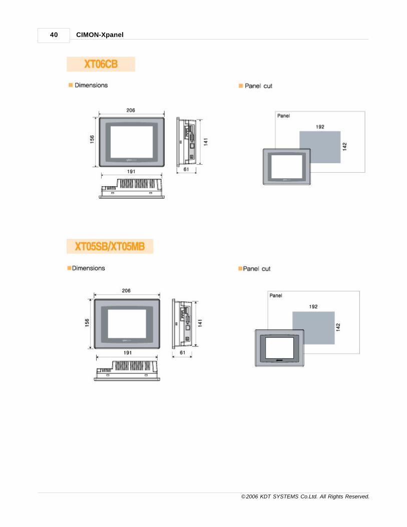
Dimension(mm) 330×250×83 280×220×47 185×127×50 206×156×61
Panel Cut(mm) 319×239 267×207 177×119 192×142
ModelCM-XT05SB-A CM-XT05MB-
ACM-XT04CA-D+LAN CM-XT04CA-D
CM-XT05SB-D CM-XT05MB-D
LCD SIZE 5.7 Inch 4.3 inch wide
LCD TYPE Color STN Mono TFT Color
Colors 256 Colors 16 shaded 16.7M colors
Resolution QVGA 320 × 240 WQVGA 480 × 272
Backlight LED LCD
Luminance 350 cd / 200 cd / 300 cd /
Touch Panel 4 wire registive 4 wire registive

CIMON-Xpanel38
© 2006 KDT SYSTEMS Co.Ltd. All Rights Reserved.
Memory 64MB SDRAM 64MB SDRAM
storage 32MB Flash 32MB Flash
COM1 RS-232 RS-232
COM2 RS-422/485 RS-422/485
Ethernet 10/100 Base-T 10/100 Base-T None
USB Host 1 Port 1 Port
Tool port 1 USB device 1 USB device
SD CARD None None
Rated Voltage -A : AC100~240V / -D: DC24V DC24V
PowerConsumption
6W 4W
OS Windows CE 5.0 Windows CE 5.0
Dimension(mm) 206×156×61 128×102×50
Panel Cut(mm) 192×142 120×94
4.5 Installation / Dimensions
[XT12CB / XT10CB / XT07CB / XT06CB / XT05SB / XT05MB / XT04CA ]

Installation Guide 39
© 2006 KDT SYSTEMS Co.Ltd. All Rights Reserved.
CIMON-Xpanel40
© 2006 KDT SYSTEMS Co.Ltd. All Rights Reserved.

Installation Guide 41
© 2006 KDT SYSTEMS Co.Ltd. All Rights Reserved.
4.6 Interfaces
XT10/ XT12 - COM1 : RS-232C
This interface is used to connect the Xpanel to the host (PLC), via an RS-232C cable.
When you use COM1 RS-232C port, you must not use COM1 RS-485/422 port.
Connector Pin No Name Description
1 DCD Data Carrier Detect
2 RD Receive Data
3 TD Transmit Data
4 DTR Data Terminal Ready
5 SG Signal Ground
6 DSR Data Set Ready
7 RTS Request To Send
8 CTS Clear To Send
9 RI Ring Indicator
XT10/XT12 - COM1 : RS-422/485
This interface is used to connect the Xpanel to the host (PLC), via an RS-422/485 cable.
When you use COM1 RS-422/485 port, you must not use COM1 RS-232C port.

CIMON-Xpanel42
© 2006 KDT SYSTEMS Co.Ltd. All Rights Reserved.
Connector Pin No Name Description
1 RDB Receive Data B
2 RDA Receive Data A
3 GND Ground
4 SDB Send Data B
5 SDA Send Data A
If you connect the Xpanel to the host via an RS-485 cable (2wire), you must connect SDA and SDB lines.
The RS-485 of the Xpanel runs under auto toggle mode. To reduce the risk of damaging the RS-422 circuit,
be sure to connect the SG terminal.
XT10/XT12 - COM2 : RS-232C
XT10A and XT12A series units have this interface.
This interface is used to connect the Xpanel to the host (PLC), via an RS-232C cable. You can use pin 2, 3,
5 of this interface.
Connector Pin No Name Description
1
2 RD Receive Data
3 TD Transmit Data
4
5 SG Signal Ground
6
7
8
9
The serial port of the Xpanel is not isolated. When the host(PLC) unit is also not isolated.
Inside the Xpanel unit, the SG (Signal Ground) and FG (Frame Ground) terminals are connected to each
other.
When connecting an external device to the Xpanel with the SG terminal, ensure that no short-circuit loop is
created when you setup the system.
XT04/ XT07 COM1 : RS-232C / COM2 : RS-422/485
This interface is used to connect the xpanel to the host (PLC), via an RS-232C or RS-422/485 cable. COM1
and COM2 shares pins of one 9 DSUB connector.

Installation Guide 43
© 2006 KDT SYSTEMS Co.Ltd. All Rights Reserved.
· If you connect the Xpanel to the host via an RS-485 cable (2wire) you must connect SDA and SDB lines.
· The RS-485 of the Xpanel runs under auto toggle mode.
· To reduce the risk of damaging the RS-422 circuit, be sure to connect the SG terminal.
Ethernet
This interface complies with the IEEE802.3 for Ethernet (10BaseT/100BaseTX).
RJ45 Connector RJ45 Jack
Direct Cable: Host <-> HUB
Cable No Color Color No Cable
1 Orange/W Orange/W 1
2 Orange Orange 2
3 Green/W Green/W 3
4 Blue Blue 4
5 Blue/W Blue/W 5
6 Green Green 6
7 Brown/W Brown/W 7
8 Brown Brown 8

CIMON-Xpanel44
© 2006 KDT SYSTEMS Co.Ltd. All Rights Reserved.
Crossover Cable: Host <-> Host
Cable No Color Color No Cable
1 Orange/W Green/W 1
2 Orange Green 2
3 Green/W Orange/W 3
4 Blue Blue 4
5 Blue/W Blue/W 5
6 Green Orange 6
7 Brown/W Brown/W 7
8 Brown Brown 8
4.7 Wiring
WARNINGS
· To avoid an electric shock, when connecting the Xpanel power cord terminals to the power terminal
block,
confirm that the Xpanel power supply is completely turned OFF, via a breaker, or similar unit.
· Since there is no power switch on the Xpanel unit, be sure to attach a breaker-type switch to its power
cord.
Point
· To avoid a short caused by loose ring terminals, be sure to use ring terminals with an
insulating sleeve.
· When the FG terminal is connected, be sure the wire is grounded.
Not grounding the Xpanel unit will result in excess noise and vibration.
Connecting the Xpanel Power Cord
When connecting the power cord, be sure to follow the procedures given below.
· Confirm that the Power Cord is unplugged from the power supply.
· Unscrew the screws from the middle three (3) terminals, align the Ring Terminals and re-attach the
screws.
Point
· Confirm that the ring terminal wires are connected correctly.
· The torque required to tighten these screws is 0.5 to 0.6 N·m.

Installation Guide 45
© 2006 KDT SYSTEMS Co.Ltd. All Rights Reserved.
Power Supply Caution
Please pay special attention to the following instructions when connecting the power cord terminals to the
Xpanel unit.
· If the power supply voltage exceeds the GP's specified range, connect a voltage transformer.
· Between the line and the ground, be sure to use a low noise power supply. If there is still an excessive
amount of noise, connect a noise reducing transformer.
· The power supply cord should not be bundled with or kept close to main circuit lines (high voltage,
high current), or input/output signal lines.
· Connect a surge absorber to handle power surges.
· To reduce noise, make the power cord as short as possible.
Grounding Caution
· When grounding to the rear face FG terminal of the Xpanel, (on the Power Input Terminal Block), be sure
to create an exclusive ground.
· Inside the Xpanel unit, the SG (Signal Ground) and FG (Frame Ground) terminals are connected to each
other.
· When connecting an external device to the Xpanel with the SG terminal, ensure that no short-circuit loop
is created when you setup the system.
4.8 Developing Environment Setup
Install XpanelDesigner
Following procedure assumes that the XPanelDesigner was installed first.
You can find the setup program of XPanelDesigner in CD or internet web page (http://www.kdtsys.com/)
ActiveSync Setup
Install ActiveSync using afforded CD when you purchased Xpanel. If you lost afforded CD, you can
download it by internet.
You can do installation as the following figure.

CIMON-Xpanel46
© 2006 KDT SYSTEMS Co.Ltd. All Rights Reserved.
If you could see the dialog box above, then select “Next”.
Click the check box as the above figure, then select “Next”.

Installation Guide 47
© 2006 KDT SYSTEMS Co.Ltd. All Rights Reserved.
Input User Name and Organization in the blank and then select “Next”.
Select ‘Destination Folder’ in your hard disc, and then select “Next”.

CIMON-Xpanel48
© 2006 KDT SYSTEMS Co.Ltd. All Rights Reserved.
If you could see the dialog box above, then select “Finish” and then restart your computer.
Install the Device Driver
Connect the XPanel unit and PC with USB cable after installation of ActiveSync. And then, you have to
reboot the Xpanel.
If it was the first time connecting with Xpanel then your PC requires device driver configuration as shown in
the following dialog box.

Installation Guide 49
© 2006 KDT SYSTEMS Co.Ltd. All Rights Reserved.
Select Check button as the above figure then “Next”.
Insert CD provided with XPanel unit, and then select “Next”.
If you don’t have CD, then you can choose the location of device driver manually as shown in the following
dialog box.
This assumes that XPanelDesigner was installed in your PC already.

CIMON-Xpanel50
© 2006 KDT SYSTEMS Co.Ltd. All Rights Reserved.
Give the location as shown in the above dialog box. Typically, the device driver can be found in “C:
\Program Files\XPanel\XPanel_Driver” folder.
If the device was searched successfully, then the above dialog box would be shown. Click the “Finish”
button.
Connect the Xpanel unit and PC with USB cable
Whenever your computer or XPanel was restarted, you would see the following dialog box.

Installation Guide 51
© 2006 KDT SYSTEMS Co.Ltd. All Rights Reserved.
Select check button as above the figure and then select “Next”.
Then you can see as the following figure it means ActiveSync installation success.

Top Level IntroThis page is printed before anew top-level chapter starts
Part
V

SYSTEM Overview 53
© 2006 KDT SYSTEMS Co.Ltd. All Rights Reserved.
5 SYSTEM Overview
· Xpanel supports various kinds of peripherals.
· Xpanel supports not only 1:1 network but also multi-drop topology.
· Xpanel Designer is a free software. It can be run on the standard Microsoft Windows platform such as
Windows XP.
· Xpanel unit always searches a project files for execution at start up.
System Overview
· Peripherals
· Network
· Xpanel Designer
· Xpanel Unit
5.1 Peripherals
Xpanel supports various kinds of peripherals. For those peripheral connection, Xpanel provides following
interfaces :
USB Client This interface is used for Xpanel Designer interface. By using this port, all configuration
data files including the
screen drawings can be up and downloaded. Xpanel Designer software is a free software.

CIMON-Xpanel54
© 2006 KDT SYSTEMS Co.Ltd. All Rights Reserved.
It is provided by CD
and can be downloaded through the internet. (http://www.kdtsys.com)
Xpanel Designer is a Microsoft Windows based software. And for connection with Xpanel, it
uses another software on
PC, the Microsoft ActiveSync. The ActiveSync is provided by CD, but also can be
downloaded from Microsoft web sites.
USB Host This interface can be used for many kinds of peripherals such as printers, memory sticks,
barcode scanners and
keyboards. For connection of multiple of them, the USB hub can be utilized.
SD/MMC
Memory Slot
SD/MMC memory slot can be used for storage expansion and/or upgrading project files.
The Xpanel provides standard 8MB internal flash memory. If this storage was not enough
for storing all project data
files, external SD/MMC or USB memory can be used.
Xpanel detects SD/MMC or USB memory automatically. And if there are required folder and
files in external memory,
Xpanel will load the project files from that external memory at startup. In this case, the
project files of internal flash
memory will be ignored.
5.2 Network
Xpanel supports not only 1:1 network but also multi-drop topology.
And more, Xpanel can communicate with several different devices and networks on the same time.
SYSTEM Overview 55
© 2006 KDT SYSTEMS Co.Ltd. All Rights Reserved.
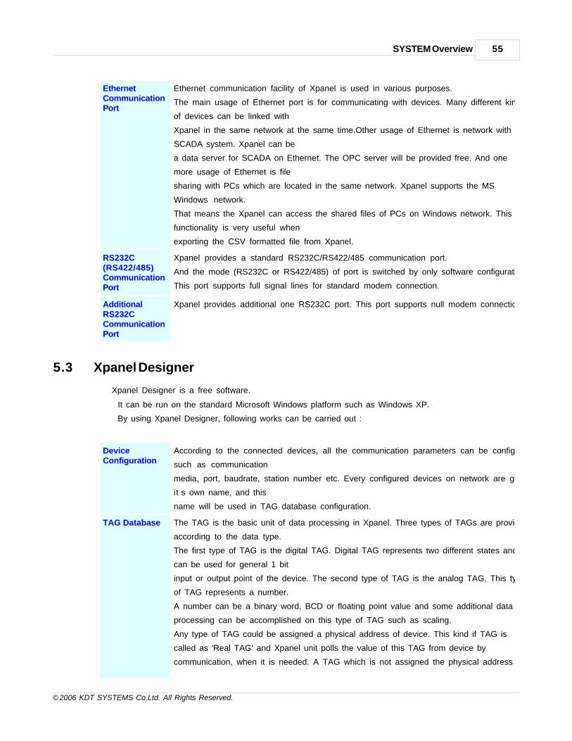
EthernetCommunicationPort
Ethernet communication facility of Xpanel is used in various purposes.
The main usage of Ethernet port is for communicating with devices. Many different kinds
of devices can be linked with
Xpanel in the same network at the same time.Other usage of Ethernet is network with
SCADA system. Xpanel can be
a data server for SCADA on Ethernet. The OPC server will be provided free. And one
more usage of Ethernet is file
sharing with PCs which are located in the same network. Xpanel supports the MS
Windows network.
That means the Xpanel can access the shared files of PCs on Windows network. This
functionality is very useful when
exporting the CSV formatted file from Xpanel.
RS232C(RS422/485)CommunicationPort
Xpanel provides a standard RS232C/RS422/485 communication port.
And the mode (RS232C or RS422/485) of port is switched by only software configuration.
This port supports full signal lines for standard modem connection.
AdditionalRS232CCommunicationPort
Xpanel provides additional one RS232C port. This port supports null modem connection.
5.3 Xpanel Designer
Xpanel Designer is a free software.
It can be run on the standard Microsoft Windows platform such as Windows XP.
By using Xpanel Designer, following works can be carried out :
DeviceConfiguration
According to the connected devices, all the communication parameters can be configured
such as communication
media, port, baudrate, station number etc. Every configured devices on network are given
it’s own name, and this
name will be used in TAG database configuration.
TAG Database The TAG is the basic unit of data processing in Xpanel. Three types of TAGs are provided
according to the data type.
The first type of TAG is the digital TAG. Digital TAG represents two different states and
can be used for general 1 bit
input or output point of the device. The second type of TAG is the analog TAG. This type
of TAG represents a number.
A number can be a binary word, BCD or floating point value and some additional data
processing can be accomplished on this type of TAG such as scaling.
Any type of TAG could be assigned a physical address of device. This kind if TAG is
called as 'Real TAG' and Xpanel unit polls the value of this TAG from device by
communication, when it is needed. A TAG which is not assigned the physical address of
CIMON-Xpanel56
© 2006 KDT SYSTEMS Co.Ltd. All Rights Reserved.
device is called as 'Virtual TAG'. Virtual TAG is used for internal data calculation, script
programming and string data manipulation.
Screen Editor Xpanel Designer provides it’s own graphic editor. It is an object based graphic editor.
Each graphic object can be configured with some animation controls. There are many
kinds of animation controls
supported such as blinking, visualizing, coloring, moving, rotating, digitizing, zooming and
more.
These all animations are triggered by the value of designated TAG in Xpanel unit.
The Xpanel provides abundant graphic libraries and supports true type fonts, also.
ScriptProgramming
Xpanel provides ‘C’ style script language of it’s own.
This script language supports inherent ‘C’ language keywords such as ‘switch-case’
statement.
And more, Xpanel unit provides priority controlled multi-threading environment for that
script program.
This script language can be used not only for data processing but also for device control.
Xpanel Unit Upgrade
Every Xpanel Designer releases have it’s own version of binary files for Xpanel unit. And
when connected first time
with Xpanel unit, the Xpanel Designer detects the version of Xpanel unit, and if needed,
upgrade the binary files in
Xpanel unit automatically.
Xpanel Designer provides a tool for making memory image of SD/MMC or USB. This
image includes project folders
and files for Xpanel unit. On start-up, Xpanel unit searches this image in external memory.
If it was found, Xpanel unit
uses this image as a project data, and the one in internal flash memory will be ignored.
This is useful when a user do
not want to use a PC or notebook for project data update. The user can change the
configuration or the design of
screen with a memory card only.
ConfigureOtherFunctions
Xpanel provides many special functions for Xpanel application such as data logger, alarm,
trend, recipe and
network service. All these functions can be configured in Xpanel Designer.
5.4 Xpanel Unit
Xpanel unit always searches a project files for execution at start up.
Following diagram shows the order of that search. If the project files are found at one of three locations, Xpanel
unit load those project files to execute.

SYSTEM Overview 57
© 2006 KDT SYSTEMS Co.Ltd. All Rights Reserved.
After the loading of project files, all configured tasks are executed concurrently.
The task execution in an Xpanel unit is performed by time-sharing and multi-threading with priority.
Graphic processing and file manipulation in Xpanel are processed by time sharing. But, almost other tasks
are executed by means of multi-threading.
The priority based multi-threading makes it possible to process real-time data. Communication and script are
good examples for priority based multi-threaded task.
On the other hand, Xpanel provides some tools for maintenance during runtime. These tools can be
visualized by three step touch screen operations.
Following picture shows these operations of touch screen.
After these touch operations, a dialog box will be appeared on screen and you can see the following
services for maintenance.
System Log An Xpanel logs the system activities in memory during its runtime.
This service makes you can see those logged messages.
Comm.
Monitor
Communication frames between the Xpanel and devices can be visualized with this
service.
Comm.
Port
Configuration
Communication parameters can be configured by this service.
IP address, baudrate and other parameters of communication port are listed on the
dialog box, and can be
changed by common control interfaces of Windows.

CIMON-Xpanel58
© 2006 KDT SYSTEMS Co.Ltd. All Rights Reserved.
Misc.
Configurations
LCD backlight and beep sound can be configured by this service.
Touch
Calibration
This service provides a chance to calibrate touch panel of Xpanel.
Clock Setting The real time clock can be adjusted by this service.
Software
Keyboard
The Xpanel has a software keyboard interface. This service visualizes or hides the
software keyboard on screen.
Xpanel
Shutdown
This service shutdowns the Xpanel program on Xpanel unit.
Suspend This service shutdowns the operating system of Xpanel unit.
When the IP address is changed, this service must be activated. After the system
shutdown, the system
will not be restarted automatically. The external power must be turned off and on again
for system restart.

Top Level IntroThis page is printed before anew top-level chapter starts
Part
VI

CIMON-Xpanel60
© 2006 KDT SYSTEMS Co.Ltd. All Rights Reserved.
6 Configuration Tools
Xpanel provides several online configuration tools.
The configuration tools can be visualized by pressing three corners of touch area as shown in left picture.
After pressing each corner one by one, the following dialog box is popped up. All the configuration tools are
shown in this dialog box.
· System Log
· Comm Monitor
· Comm. Config
· Misc. Config
· Touch Calibrate
· Screen Capture
· Date/Time
· SW Keyboard
· Printer
· System Shoutdown
· Exit
6.1 System Log : System Activity Log
The Xpanel logs the system activities in memory during its runtime. This service makes you can see those
logged messages.

Configuration Tools 61
© 2006 KDT SYSTEMS Co.Ltd. All Rights Reserved.
6.2 Comm. Monitor : Communication Frame Monitor
Communication frames between the Xpanel and devices can be monitored with this service.
Start / Pause Starts or pauses the communication frame logging job.
The frame marked as ‘[TX ]’ is the frame transmitted from Xpanel.
And the frame marked as ‘[RX]’ is the frame received from a device.
Clear Clears all logged frame from the list.
ASCII / BIN Sets the data coding format of the frame. When the ‘ASCII’ format is chosen, only the data
between 20h to 7Fh
are displayed correctly. Other data will be seen as broken character. And when the ‘BIN’

CIMON-Xpanel62
© 2006 KDT SYSTEMS Co.Ltd. All Rights Reserved.
format is chosen,
all the data is displayed in hexa-decimal number.
Resize Changes the window size. Xpanel provides two differently sized windows.
One is full-window sized and the other is small sized window.
(The small sized window is the best fitting size for 5.6 inch LCD)
6.3 Comm. Config : Communication Port Configruation
Communication parameters can be configured by this service.
IP address, baudrate and other parameters of communication port are listed on the dialog box, and can be
changed by common control
interfaces of Windows. When the ‘Comm. Config’ tool is activated, following dialog box is popped up.
First of all, the communication port to be configured must be selected. As shown in the above picture, the
operator can select one of ports being used.
The port combo-box lists the names of device which are registered in current project.
Serial Port (COM1 / COM2)
When a serial device is chosen for port configuration, following parameters can be configured.
All the parameter modifications are applied immediately to the current running project.

Configuration Tools 63
© 2006 KDT SYSTEMS Co.Ltd. All Rights Reserved.
Xpanel’s COM1 port can be used for three kinds of network type. Available network types are RS232C,
RS422A and RS485.
One of them can be chosen by using this tool as shown in right-hand picture of above.
The actual terminal block for COM1 is decided according to this configuration.
The modem parameters are prepared for special purpose application. It is dependent on the
communication driver used.
Following pictures shows the parameters for dial-up modem application.
Ethernet Port
When an Ethernet device is chosen for port configuration, following parameters can be configured.
All the parameter modifications are applied immediately to the current running project.

CIMON-Xpanel64
© 2006 KDT SYSTEMS Co.Ltd. All Rights Reserved.
But for storing the new configuration permanently, "System Shutdown" is needed. Refer to the ‘section
11’ of this chapter.
Another Method for Ethernet Configuration
The standard WinCE operating system provides another way to configure Ethernet. It can be done in
desktop window.
The desktop window can be accessed only when the Xpanel program is closed.
For closing the Xpanel program, use the ‘Exit’ button. (The ‘Exit’ button is described in the ‘section 12’ of
this chapter)
1. First of all, execute and put a software keyboard on the desktop window.
This keyboard will be used during the network configuration. For doing this, make the task bar visible
as shown in the following picture.

Configuration Tools 65
© 2006 KDT SYSTEMS Co.Ltd. All Rights Reserved.
2. Execute the software keyboard by touching the icon at the right corner of the task bar, and select
‘LargeKB’ menu.
The software keyboard will be popped up as shown in following picture.
3. The next step is executing the LAN configuration tool. Follow the icons listed below, started from the
desktop window.
The setting dialog box of above can be accessed by the software keyboard which is prepared at the
previous step.

CIMON-Xpanel66
© 2006 KDT SYSTEMS Co.Ltd. All Rights Reserved.
4. For storing the network settings permanently, it is needed to ‘suspend’ the operating system.
This can be done by the ‘Suspend’ menu of ‘Start’ tool as shown in the following picture.
6.4 Misc. Config : Miscellaneous Configurations
LCD backlight
OFF
It provides a sleeping function for LCD backlight.
The time span is based on the unit of minute. If there is no touch operation during this
time span,
the backlight of LCD is turned off automatically. The backlight will be turned on when there
is any touch operation.
Mouse cursor
enable
Mouse cursor display is dependent on this option. This option is effective only on the
following version of OS and XpanelDesigner.
· OS : V1.15
· XpanelDesigner ; V1.30
LCD Brightness Operator can control the LCD brightness by this function. Up to 32 brightness levels are
provided by hardware. This function is supported by following version of OS.
· OS : V1.17

Configuration Tools 67
© 2006 KDT SYSTEMS Co.Ltd. All Rights Reserved.
6.5 Touch Calibrate : Touch Panel Calibration
Touch
Calilbrate
This service provides a chance to calibrate touch panel of Xpanel.
Follow the instruction message shown at the top of the screen.
Point
For storing the new calibration data permanently, ‘System Shutdown’ is needed. Refer to the ‘section 11’ of
this chapter.
If the ‘System Shutdown’ was not executed, the new calibration data will be discarded and the previous one
will be restored
when the system is restarted.

CIMON-Xpanel68
© 2006 KDT SYSTEMS Co.Ltd. All Rights Reserved.
6.6 Screen Capture : Make a Screen Snapshot
Screen Capture This service makes a screen capture file of current display. Generated file has bitmap
(BMP) formatted file and located in the " \ X p a n e l \" folder. File name is given automatically,
and has following format which is derived
from clock.
6.7 Date/Time : Adjust the System Clock
Date / Time The real time clock can be adjusted by this service.

Configuration Tools 69
© 2006 KDT SYSTEMS Co.Ltd. All Rights Reserved.
6.8 SW Keyboard : Pops-Up the Software Keyboard
Date / Time The Xpanel has a software keyboard interface.
This button visualizes or hides the software keyboard on screen. Following picture shows
the software keyboard.
For removing the software keyboard from screen, use the ‘SW Keyboard’ button again.
6.9 Printer : Printer Setup
Printer Xpanel supports the PCL. The laser or inkjet type printers supporting PCL can be
connected with Xpanel through the USB or network.

CIMON-Xpanel70
© 2006 KDT SYSTEMS Co.Ltd. All Rights Reserved.
Point
For storing the setup permanently, ‘System Shutdown’ is needed after this setup procedure. Refer to the
‘section 11’ of this chapter.
If the ‘System Shutdown’ was not executed, the setup data will be discarded and the previous one will be
restored when the system is restarted.
Print Configuration Dialog Box
Following picture shows the print configuration dialog box.
Printer Select the type of connected printer. The type can be one of ‘PCL Inkjet’ or ‘PCL Laser’.
Port Select a port where the printer is connected.
· USB Printer : If a printer is connected to the Xpanel though the USB host port,
select the "LPT1:" The LPT1 port is automatically detected and displayed only when
the printer is connected.
· Network Printer : If a printer can be reached through the network,
select the "Network ". In this case, the ‘Net Path’ field must be configured as
following example.
Format \ \PC_name\Printer_name
Example \ \ k i m 4 0 \ c a n o n i r 2
The software keyboard would be needed for setting the network path.
The software keyboard can be shown by ‘SW Keyboard’ service. Please refer to the
previous section
(section 11 : SW Keyboard) of this chapter.

Configuration Tools 71
© 2006 KDT SYSTEMS Co.Ltd. All Rights Reserved.
Network Printer Logon
If the ‘Port’ is chosen as ‘Network’, the Xpanel tries to connect the PC through network and pops-up
following logon dialog box.
Enter the authorized user name and password to the logon dialog box above, and then push the button
in title bar.
Xpanel will pop up following dialog box.
If ‘Yes’ is chosen, the password entered will be stored in disk permanently.
Otherwise (in case of ‘No’), the Xpanel will ask the password whenever try to use the network printer.
How to print a screen?
Xpanel provides the ‘HardCopy()’ function for printing the screen image. The HardCopy() function is
explained in the ‘Script’ chapter.

CIMON-Xpanel72
© 2006 KDT SYSTEMS Co.Ltd. All Rights Reserved.
An example which prints a screen image by a touch operation is provided in this section.
For printing a screen, a touch object should be declared in the graphic page.
This touch object must have the property of ‘Command Expression’ style and ' HardCopy()' function has to
be declared in its ‘Command’ input field.
Previous picture shows the situation of configuration with the Xpanel Designer.
Following picture is a snapshot of the Xpanel online screen. Assume that this screen is configured as
described above.
When the operator touches the ‘Screen Print’ object, the Xpanel prints current displaying screen out.
The operator will be notified the successful printing by following pop-up dialog box, some seconds after.

Configuration Tools 73
© 2006 KDT SYSTEMS Co.Ltd. All Rights Reserved.
6.10 System Shutdown
System
shutdown
This service shutdowns the operating system of Xpanel unit.
The system shutdown must be done when there is a change in one of following items.
· Ethernet Port Configurations (IP address, Subnet Mask and/or Gateway)
· Touch Calibration
· Printer Setup
After the system shutdown, the system will not be restarted automatically. The external power must be turned
off and on again for system restart.
Point

CIMON-Xpanel74
© 2006 KDT SYSTEMS Co.Ltd. All Rights Reserved.
This has the same effect with the ‘Suspend’ function of ‘Start’ menu in desktop
window.
6.11 Exit
Exit This service exits the Xpanel program and return to the desktop window as shown in
following picture.
In this desktop window, following jobs can be performed.
· File system manipulation with explorer
· Some system configurations with control panel (clock, network etc.)
· System status checking. (disk and memory status etc.)
To execute the Xpanel again, double touch the icon of desktop.

Top Level IntroThis page is printed before anew top-level chapter starts
Part
VII

CIMON-Xpanel76
© 2006 KDT SYSTEMS Co.Ltd. All Rights Reserved.
7 Xpanel Designer
For details on Xpanel Designer, refer to the following manual
Xpanel Designer
· How to download the project data
· Xpanel Designer Installing and Running
· Xpanel Designer menu
· Project setup and download
7.1 How to download project data
IN THIS TOPIC :
Using USB port Using Ethernet port Using removable memory
This manual explains download method for Xpanel project to Xpanel from Xpanel Designer. Xpanel supports
three ways for download project.
There are three different methods to download the Xpanel project data as summarized here:
· Using USB port (supported model : XT04CA, XT05MB, XT05SB, XT06CB, XT07CB)
· Using Ethernet port(supported model : Products that Ethernet port is supported in products of OS Version
2.00 or late)
· Using removable storage (supported model : Products that USB Host and SD slot are supported in
products of OS Version 2.00 or late)
Using USB port
This method downloads project using Xpanel’s USB Tool port.
Before download project, you must install Xpanel device driver and ActiveSync.
Install theActiveSync
Xpanel provides ActiveSync in the including CD but you can also download latest version from
Microsoft homepage (www.microsoft.com). After Installation, you need to restart your PC.
Install theXpanel DeviceDirver
After rebooting, connect the Xpanel with PC by USB cable.

Xpanel Designer 77
© 2006 KDT SYSTEMS Co.Ltd. All Rights Reserved.
Select as like the following figure and click [Next] at the Hardware update wizard.

CIMON-Xpanel78
© 2006 KDT SYSTEMS Co.Ltd. All Rights Reserved.
Insert provided CD and click [Next].
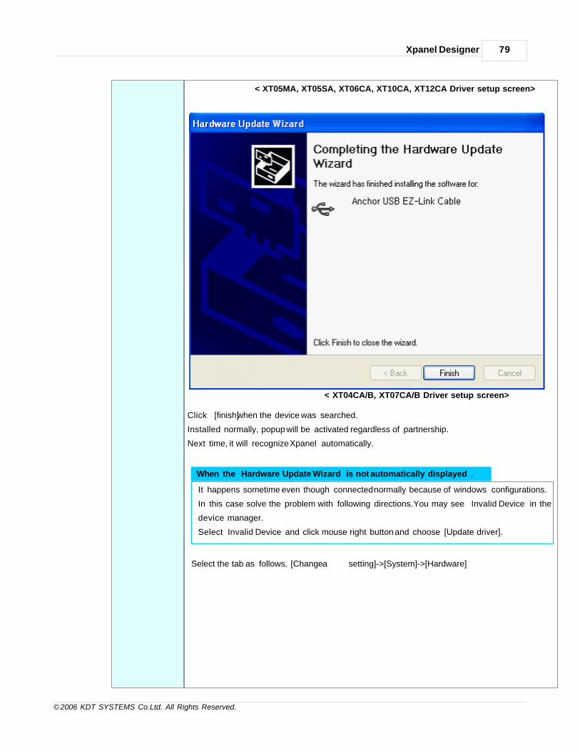
Xpanel Designer 79
© 2006 KDT SYSTEMS Co.Ltd. All Rights Reserved.
< XT05MA, XT05SA, XT06CA, XT10CA, XT12CA Driver setup screen>
< XT04CA/B, XT07CA/B Driver setup screen>
Click [finish] when the device was searched.
Installed normally, popup will be activated regardless of partnership.
Next time, it will recognize Xpanel automatically.
When the ‘Hardware Update Wizard’ is not automatically displayed .
It happens sometime even though connected normally because of windows configurations.
In this case solve the problem with following directions. You may see “Invalid Device” in the
device manager.
Select ‘Invalid Device’ and click mouse right button and choose [Update driver].
Select the tab as follows. [Change a setting]->[System]->[Hardware]

CIMON-Xpanel80
© 2006 KDT SYSTEMS Co.Ltd. All Rights Reserved.
Select as like above the figure, then click [Next].

Xpanel Designer 81
© 2006 KDT SYSTEMS Co.Ltd. All Rights Reserved.
Driver file path will be different according to the OSversion.
- If Xpanel models are XT04CA, XT05MB, XT05SB, XT06CB, XT07CB, this models are
select following path.
“Xpanel_Driver\ XT04_Sync_Drv” in the XpanelDesigner installed folder.
(Ex : C:\Program Files\Xpanel\Xpanel_Driver)
- If OS version is below 1.19, it will direct the path folder “Xpanel_Driver” in the
XpanelDesigner installed folder.
(Ex : C:\Program Files\Xpanel\Xpanel_Driver)
- If OS version is above 1.19, it will direct the path folder “Drivers” in the ActiveSync
installed folder.
(Ex : C:\Program Files\Microsoft ActiveSync\Drivers)
[Windows CE USB device] will be registered in the Device Manager with the massage as setup
is complete.
Setup Link Run XpanelDesigner. Load the project that will be downloaded. Select [Online]->[Connection].
You can execute ‘Project download’ or ‘Project upload’ from ‘online’ menu of the
XpanelDesigner.
* Although you have several USB port in your PC, you can download project via only one of
them.
Using Ethernet port
If Xpanel is connected with PC by the Ethernet, you can download the project through Ethernet
without USB cable.
Connect PC with Xpanel to download the project using Ethernet port and configure IP address.

CIMON-Xpanel82
© 2006 KDT SYSTEMS Co.Ltd. All Rights Reserved.
* For using this method, it needs OS version above 2.00 and XpanelDesigner version 1.37 orlate.
ConfirmtheIPofthePC
Select [Start]->[Run] on the PC.
Input “cmd” at the RUN window.
Input “ipconfig” at the Command window.
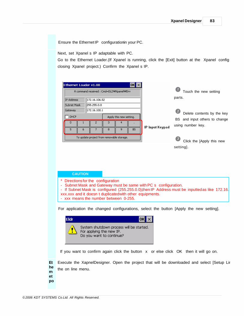
Xpanel Designer 83
© 2006 KDT SYSTEMS Co.Ltd. All Rights Reserved.
Ensure the Ethernet IP configuration in your PC.
Next, set Xpanel’s IP adaptable with PC.
Go to the Ethernet Loader.(If Xpanel is running, click the [Exit] button at the “Xpanel config” for
closing Xpanel project.) Confirm the Xpanel’s IP.
Touch the new setting
parts.
Delete contents by the key
‘BS’ and input others to change
using number key.
Click the [Apply this new
setting].
CAUTION
* Directions for the configuration- Subnet Mask and Gateway must be same with PC’s configuration.- If Subnet Mask is configured (255.255.0.0), then IP Address must be inputted as like 172.16.xxx.xxx and it doesn’t duplicated with other equipments.- xxx means the number between 0-255.
For application the changed configurations, select the button [Apply the new setting].
If you want to confirm again click the button “x” or else click “OK” then it will go on.
Ethernetpo
Execute the XapnelDesigner. Open the project that will be downloaded and select [Setup Link] at
the on line menu.
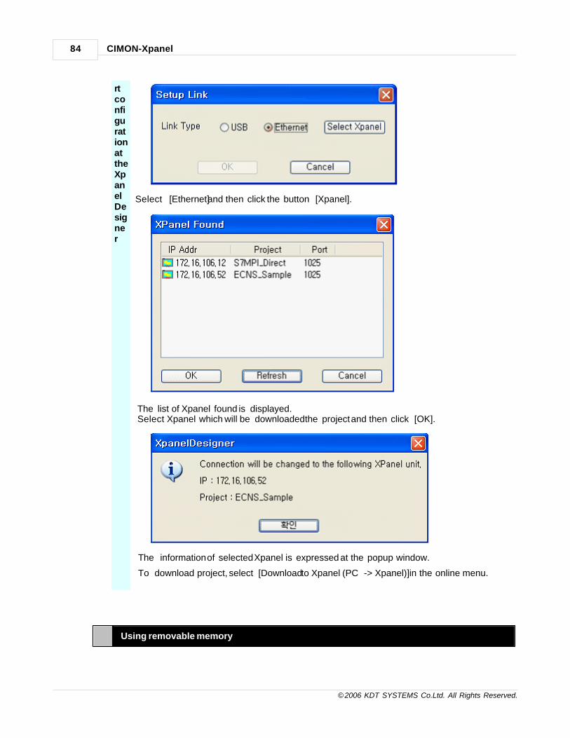
CIMON-Xpanel84
© 2006 KDT SYSTEMS Co.Ltd. All Rights Reserved.
rtconfigurationattheXpanelDesigner
Select [Ethernet] and then click the button [Xpanel].
The list of Xpanel found is displayed.Select Xpanel which will be downloaded the project and then click [OK].
The information of selected Xpanel is expressed at the popup window.
To download project, select [Download to Xpanel (PC -> Xpanel)] in the online menu.
Using removable memory

Xpanel Designer 85
© 2006 KDT SYSTEMS Co.Ltd. All Rights Reserved.
Xpanel supports the download function for removable memory.
If you use this function, you can update the Xpanel’s project without connecting it directly by using
like USB memory that is a kind of portable disc drive.
* This function is required Xpanel model that supports USB Host or SD card slot. You need alsoOS version above 2.00 and XpanelDesigner version 1.37 or late.
Copy projectto memorycard
Insert memory card to your PC.
Select [Copy Project To Removable Memory] in the Online menu of
XpanelDesigner.
Select or Input the path to download project.
Download path must be indicated root of disc. If you check the “Download the
Editing project”, it includes the data for upload.
If it is done, complete message box will be popped up.
Updateproject fromremovablestorageto Xpanel.
Insert removable storage to Xpanel which has been downloaded project.

CIMON-Xpanel86
© 2006 KDT SYSTEMS Co.Ltd. All Rights Reserved.
Click project update button at the Ethernet Loader as shown up.
Then ‘Project Update’ window is popped up and it will display updatable projects
after search.
If you want to search list again, click [Refresh] button.
Select the project will be downloaded at the list and click [Project Update] button.
* When project is updated, it will remove previous project first of all. Please attention.
When the project is downloading, [Project Update] button is not executed.
After it is completed download project, you can see the message “All file update : OK”
and [Project Update] button is executed again. Be careful, if you touch it while working,
it would be canceled.
7.2 Xpanel Designer Installing and Running
1. You can download XpanelDesigner v2.10 from internet homepage (http://www.kdtsys.com/).
Xpanel Designer Suggestion

Xpanel Designer 87
© 2006 KDT SYSTEMS Co.Ltd. All Rights Reserved.
If the past version of ‘Xpanel Designer’ is installed, please remove it by ‘Program add/delete’.
2. Select window[Start] -> [Xpanel] -> [Xpanel Designer]
7.3 Xpanel Designer menu
IN THIS TOPIC :
File Edit Draw View Online Arrange Tools
File
button descriptions
New Page New Page is displayed.
Open Open the file of Xpanel Designer.
Close Close the present page.

CIMON-Xpanel88
© 2006 KDT SYSTEMS Co.Ltd. All Rights Reserved.
Close All Page Close the present all page.
New Project New Project is displayed.
Open Project Open the present Project.
Close Project Close the present Project.
Copy Project Copy the present Project.
Save Save the present page.
Save As. Save As. the present page.
Convert to Runtime Project Convert to Runtime Project.
Frame Editor Frame Editor is displayed.
Preview Preview before it prints.
Print Print is displayed.
Edit
button descriptions
Undo It returns before working of the edit.
Redo It cancel before working of the edit.
Cut Cut the object selected.
Copy The object selected is copied with the clipboard.
Paste Paste the object copied.
Paste Special Paste contents of clipboard.
Delate Delate the object selected.
Select All Select All object of page.
Find Find text of page or project.
Replace Replace text of page or picture, project.
Graphic File Paste Graphic File Paste.
Insert Animation Bitmap Insert Animation Bitmap.
Draw
button descriptions
Line Draw Line.

Xpanel Designer 89
© 2006 KDT SYSTEMS Co.Ltd. All Rights Reserved.
Rectange Draw Rectange.
Ellipse Draw Ellipse.
Arc Draw Arc.
Sector Draw Sector.
Chord Draw Chord.
Poly Line Draw Poly Line. It is closed to draw by double clicking.
Polygon Draw Polygon. It is closed to draw by double clicking.
Text Insert Text.
Dynamic Tag Insert Dynamic Tag.
Date Time Insert Date Time.
String Value Insert String Value.
Multi String Insert Multi String.
Trend Graph Insert Trend Graph.
DataLog Insert Trend Graph.
Key Input Window Insert Key Input Window.
Alarm Summary Insert Alarm Summary.
Library Library is displayed.
View
button descriptions
Redraw Redraw page.
Current Page Position ToRuntime
Current Page Position To Runtime.
Main Tool Main Tool is displayed.
Status Tool Status Tool is displayed.
Drawing Tool Drawing Tool is displayed.
Color Tool Color Tool is displayed.
Arrange Tool Arrange Tool is displayed.
Font Tool Font Tool is displayed.
Zoom In/Out Zoom In/Out page.
Online

CIMON-Xpanel90
© 2006 KDT SYSTEMS Co.Ltd. All Rights Reserved.
button descriptions
Setup Link You can select USB or Ethernet.
Download to Xpanel(PC->Xpanel)
Download project to Xpanel.
Upload From Xpanel(Xpanel→PC)
Upload project From Xpanel.
Make Executing RemovableMemory
Make Executing Removable Memory.
Copy Project To RemovableMemory
Copy Project To Removable Memory.
Stop Xpanel ApplicationProgram
Stop Xpanel Application Program.
Run Xpanel ApplicationProgram
Run Xpanel Application Program.
Upgrade Xpanel ApplicationProgram
Upgrade Xpanel Application Program like a Xpanel Designer.
Arrange
button descriptions
Group Make a Group by the objects selected.
UnGroup UnGroup.
ReGroup ReGroup.
Bring To Front Bring To Front.
Send To Back Send To Back.
Arrange Arrange the objects selected.
Rotate Rotate the objects selected.
Flip Flip the objects selected.
Point Change Change shape of Point.
Enable Snap Enable Snap is displayed.
Grid Config Grid Config is displayed.
Make Symbol Make Symbol the object selected.
Break Symbol Break Symbol.
Tools

Xpanel Designer 91
© 2006 KDT SYSTEMS Co.Ltd. All Rights Reserved.
button descriptions
Page Setup Page Setup is displayed.
User Library Edit Edit User Library.
Bitmap Edit Edit the Bitmap selected.
Run Simulator Run Simulator from project edited.
Run Simulator With ActivePage.
Run Simulator and open present page.
Project Project window is displayed.
Database Database window is displayed.
CIMON-Xpanel Setup Setup page and frame of CIMON-Xpanel.
I/O Devices I/O Devices are displayed.
Alarms Alarms are displayed.
Security Security is displayed.
Data Logging Data Logging is displayed.
Scripts Scripts are displayed.
String Editor String Editor is displayed.
Data Server Data Server is displayed.
Recipe Recipe is displayed.
Data Bridge Data Bridge is displayed.
Animation Editor Animation Editor is displayed.
7.4 Project setup and download
1. Select [File] -> [New Project]
2. Input "Project Name" and click - [Next>]

CIMON-Xpanel92
© 2006 KDT SYSTEMS Co.Ltd. All Rights Reserved.
3. Select "Type" of Xpanel and click - [Ok] . The page suitable for Xpanel’s resolution is made.
4. Check the condition of the page setup by double click.(or "Tools - page setup")
[Page Property]
Description When the page is opened by pop up, the description is displayed on the page.
Popup Page The position of the popup page in frame should be set of ‘None’.
Fixed BackGround For a quick screen update, set unchangeable pictures as background.
Using 256 Bitmap Using 256 Bitmap when it Convert to Runtime Project.
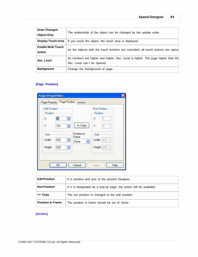
Xpanel Designer 93
© 2006 KDT SYSTEMS Co.Ltd. All Rights Reserved.
Draw Changed
Object OnlyThe relationship of the object can be changed by the update order.
Display Touch Area If you touch the object, the touch area is displayed.
Enable Multi Touch
ActionAs the objects with the touch function are coincided, all touch actions are operated.
Sec. LevelAs numbers are higher and higher, Sec. Level is higher. The page higher than the
Sec. Level can’t be opened.
Background Change the Background of page.
[Page Position]
Edit Position It is position and size of the present Designer.
Run Position If it is designated as a pop-up page, the action will be available.
=> Copy The run position is changed to the edit position.
Position In Frame The position in frame should be set of ‘None’.
[Action]

CIMON-Xpanel94
© 2006 KDT SYSTEMS Co.Ltd. All Rights Reserved.
On Opening Page Input the Action on opening page.
On Closing Page Input the Action on closing page.
[Project Download]
1. Click - [Online] -> [Setup Link] Select the link type of Xpanel.
2. Click - [Online] -> [Download to Xpanel(PC->Xpanel)]
3. "Download to Xpanel(PC->Xpanel)" is displayed.
4. Click the "Download The Editing Project" when you want to download.
The download is impossible when you download it without clicking.
5. Click the "Download The Font File" when you want to download font.

Xpanel Designer 95
© 2006 KDT SYSTEMS Co.Ltd. All Rights Reserved.
When you download it without clicking, basic Font are Kor. Xpanel : 굴림 and Eng. Xpanel : Tahoma.
6. Click - [Ok]

Top Level IntroThis page is printed before anew top-level chapter starts
Part
VIII

TAG Database 97
© 2006 KDT SYSTEMS Co.Ltd. All Rights Reserved.
8 TAG Database
This manual explains TAG database, refer to the following manual.
See :
· Overview
· Database Window
· How to use Database
· Group TAG
· Digital Tag
· Analog Tag
· String Tag
· Database edit using EXCEL
8.1 Overview
The data processing of XPanel is based on the TAG database. It should be registered with the tag shown to
the monitor.
There are three TAG types : analog, digital and string. And XPanel also provides the group TAG.
Xpanel is repeatedly getting tags’ value used in the monitor from the machinery. User can save tag's value
provided to the information of tags in the database.
So if the data is changed, the value of each tag will also be changed. When users handle buttons and input
values, following the setting information, it demands to write values in the job machinery. Additionally, as the
process to write values completes, the tag’s values are changed by reading the values from the machinery.
TAG

CIMON-Xpanel98
© 2006 KDT SYSTEMS Co.Ltd. All Rights Reserved.
Tag is a unit to save values in the database.
There are a ‘Real TAG’ and a ‘Virtual TAG’.To read and write the values of real job machinery, the real tag
should be registered and the data of the real tag also should be changed.
All tags are divided into Digital tag, Analog tag and String TAG.
For the operation to handle its values and functions, tags should be registered and set the connection
between tags and values of the machinery.
Xpanel Project and Database
Database is edited by database edit program in Xpanel Designer.
There is no tag in database in new project, so you should add tags to the database.
After Saving edited database and sending the project with database to Xpanel, Xpanel makes the operation
based on the database.
In order to change the database, edit the database of Xpanel project properly and sent the changed project to
the Xpanel.
Xpanel Database Features
•Supported data types : Digital / Analog / String
•Supports virtual TAG.
•Provides the TAG group function. (Hierarchical TAG manipulation structure)
•Easy database exporting and importing.
•Provides the last value keeping option during power off. (virtual TAG)
•Analog TAG provides data scaling option.
8.2 Database Window
Following manual is Database Window.

TAG Database 99
© 2006 KDT SYSTEMS Co.Ltd. All Rights Reserved.
Tree screen (1) This is a tree screen to quickly find the position of tags like window search.
Tag screen (2)
Registered tags are popped up to the tag screen. It gives users different Tag icon
referred to its types for a quick discernment and offers the scrollbar to let users know
easily the all information of each tag.
It can choose different tags with “Ctrl” key and click first tag and last tag by Shift that
you want to choose all tags.
Database ToolbarIt makes users to quickly add and edit the tags by Mouse.
Point
User can move a division line between tree screen and tag screen by clicking the line, but there is a
minimum area of the tree screen and the tag screen, it is ignored to make smaller window than the
minimum window.
8.3 How to use Database
How to startDatabase
· Click [File] -> [Open Project] of Xpanel Designer menu.
· Click [Tools] -> [Database] of Xpanel Designer menu.
· Click -Database icon of Xpanel Designer Toolbar.
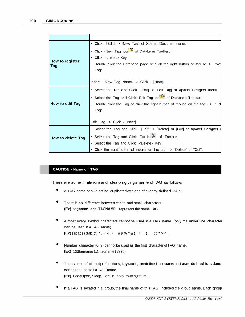
CIMON-Xpanel100
© 2006 KDT SYSTEMS Co.Ltd. All Rights Reserved.
How to registerTag
· Click [Edit] -> [New Tag] of Xpanel Designer menu.
· Click -New Tag icon of Database Toolbar.
· Click <Insert> Key.
· Double click the Database page or click the right button of mouse- > "New
Tag".
Insert - New Tag Name. -> Click - [Next].
How to edit Tag
· Select the Tag and Click [Edit] -> [Edit Tag] of Xpanel Designer menu.
· Select the Tag and Click -Edit Tag icon of Database Toolbar.
· Double click the Tag or click the right button of mouse on the tag - > "Edit
Tag".
Edit Tag -> Click - [Next].
How to delete Tag
· Select the Tag and Click [Edit] -> [Delete] or [Cut] of Xpanel Designer menu.
· Select the Tag and Click -Cut icon of Toolbar.
· Select the Tag and Click <Delete> Key.
· Click the right button of mouse on the tag - > "Delete" or "Cut".
CAUTION - Name of TAG
There are some limitations and rules on giving a name of TAG as follows :
• A TAG name should not be duplicated with one of already defined TAGs.
• There is no difference between capital and small characters.
(Ex) ‘tagname’ and ‘TAGNAME’ represent the same TAG.
• Almost every symbol characters cannot be used in a TAG name. (only the under line character
can be used in a TAG name)
(Ex) (space) (tab) @ * / + - ! ~ “ ‘ # $ % & ( ) = | \ [ ] ; : ? > < . ,
• Number character (0..9) cannot be used as the first character of TAG name.
(Ex) 123tagname (x), tagname123 (o)
• The names of all script functions, keywords, predefined constants and user defined functions
cannot be used as a TAG name.
(Ex) PageOpen, Sleep, LogOn, goto, switch, return ....
• If a TAG is located in a group, the final name of this TAG includes the group name. Each group

TAG Database 101
© 2006 KDT SYSTEMS Co.Ltd. All Rights Reserved.
name should be separated by dot (.)
character from other group or TAG name.
(Ex) “Gr1.Gr2.Gr3.pointname”
Virtual vs. Real TAG
When the ‘Virtual Tag’ radio button was chosen as following the first dialog box, the TAG does not need
the ‘I/O Device’ and ‘I/O Address’
configuration items anymore. That means, the actual value of a virtual TAG is not acquired by
communication polling but initialized and
manipulated by the internal functions of XPanel such as script.
The initial value of a virtual TAG can be defined at the ‘Advance’ configuration tab as shown in the
second dialog box of following picture.
When the XPanel is powered and starts its operation, the defined value is applied to the TAG’s initial
value. Other configuration
items in ‘Advance’ configuration tab have no meanings in case of virtual TAG.
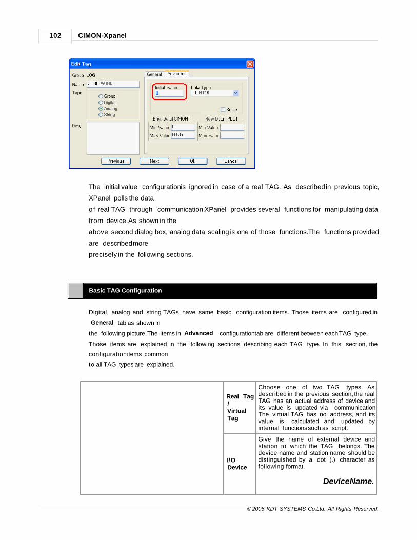
CIMON-Xpanel102
© 2006 KDT SYSTEMS Co.Ltd. All Rights Reserved.
The initial value configuration is ignored in case of a real TAG. As described in previous topic,
XPanel polls the data
of real TAG through communication. XPanel provides several functions for manipulating data
from device. As shown in the
above second dialog box, analog data scaling is one of those functions. The functions provided
are described more
precisely in the following sections.
Basic TAG Configuration
Digital, analog and string TAGs have same basic configuration items. Those items are configured in
‘General’ tab as shown in
the following picture. The items in ‘Advanced’ configuration tab are different between each TAG type.
Those items are explained in the following sections describing each TAG type. In this section, the
configuration items common
to all TAG types are explained.
Real Tag/ VirtualTag
Choose one of two TAG types. Asdescribed in the previous section, the realTAG has an actual address of device andits value is updated via communication.The virtual TAG has no address, and itsvalue is calculated and updated byinternal functions such as script.
I/ODevice
Give the name of external device andstation to which the TAG belongs. Thedevice name and station name should bedistinguished by a dot (.) character asfollowing format.
DeviceName.

TAG Database 103
© 2006 KDT SYSTEMS Co.Ltd. All Rights Reserved.
StationName
Notice that this field has meaning only ifTAG type is a real TAG.
I/OAddress
Give the real point address of the TAG.The address format is dependent on thedevice type. Refer to the device drivermanual of connected device for moreinformation such as supported addressrange, notation and data type etc.Notice that this field has meaning only ifTAG type is a real TAG.
Option : SaveLastStatusWhenClosing
This option makes the XPanel keep thelast value in flash memory when poweredoff. When the power is supplied again,XPanel restores the last value in flashmemory.Notice that this field has meaning only ifTAG type is a virtual TAG.
a TAGName of a TAG
8.4 Group TAG
When users input lots of tags at one screen, it is inefficient under its operation.
So, use a group tag to manage relative tags to make the tree structure similar with the directory in computer.
There is the purpose to make a group of various tags for better management of the project.
Basic Setup

CIMON-Xpanel104
© 2006 KDT SYSTEMS Co.Ltd. All Rights Reserved.
Name Insert a Name of Tag. (Refer to the "CAUTION - Name of Tag".)
Type Select - Type of Tag - > "Group"
Des. Input - Reference matter.
8.5 Digital TAG
XPanel provides the digital TAG type which represents a bit signal (1 or 0). All non-zero values are treatedas 1 in digital TAG.
Initial Value
Give the initial value of virtual TAG. When the XPanel is started up, the virtual TAG is initialized with
designated value.
Notice that this field has meaning only if TAG type is a virtual TAG. The real TAG ignores initial value
setting.
8.6 Analog TAG
XPanel accepts various data types from devices as an analog TAG.
All those device data types are converted to the 64 bits floating point values in XPanel.

TAG Database 105
© 2006 KDT SYSTEMS Co.Ltd. All Rights Reserved.
Initial Value
Give the initial value of virtual TAG. When the XPanel is started up, the virtual TAG is initialized with
designated value.
Notice that this field has meaning only if TAG type is a virtual TAG. The real TAG ignores initial value
setting.
Data Type
Choose one of following data types.
Type Description Value Range
INT8 Signed 8 bits integer 128 - 127
INT16 Signed 16 bits integer 32768 - 32767
INT32 Signed 32 bits integer -2147483648 - 2147483647
UINT8 Unsigned 8 bits integer 0 - 255
UINT16 Unsigned 16 bits integer 0 - 65535
UINT32 Unsigned 32 bits integer 0 - 4294967295
BCD8 Signed 8 bits BCD 79 - 79
BCD16 Signed 16 bits BCD 7999 - 7999
BCD32 Signed 32 bits BCD 79999999 - 79999999
UBCD8 Unsigned 8 bits BCD 0 - 99
UBCD16 Unsigned 16 bits BCD 0 - 9999
UBCD32 Unsigned 32 bits BCD 0- 99999999
Float 32 bits real data -3.40282e+038 - 3.40282e+038
This configuration represents the data type of device memory designated by the address defined in
‘General’ configuration tab
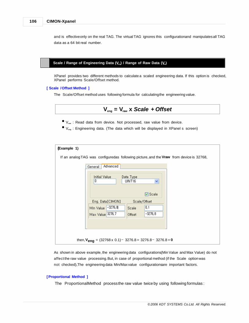
CIMON-Xpanel106
© 2006 KDT SYSTEMS Co.Ltd. All Rights Reserved.
and is effective only on the real TAG. The virtual TAG ignores this configuration and manipulates all TAG
data as a 64 bit real number.
Scale / Range of Engineering Data (Veng) / Range of Raw Data (Vraw)
XPanel provides two different methods to calculate a scaled engineering data. If this option is checked,XPanel performs ‘Scale/Offset’ method.
[ Scale / Offset Method ]
The ‘Scale/Offset’ method uses following formula for calculating the engineering value.
Veng = Vraw x Scale + Offset
•Vraw : Read data from device. Not processed, raw value from device.
•Veng : Engineering data. (The data which will be displayed in XPanel’s screen)
(Example 1)
If an analog TAG was configured as following picture, and the Vraw from device is 32768,
then, Veng = (32768 x 0.1) 3276.8 = 3276.8 3276.8 = 0
As shown in above example, the engineering data configurations (Min Value and Max Value) do not
affect the raw value processing. But, in case of proportional method (if the ‘Scale’ option was
not checked), The engineering data Min/Max value configurations are important factors.
[ Proportional Method ]
The ‘Proportional Method’ process the raw value twice by using following formulas :

TAG Database 107
© 2006 KDT SYSTEMS Co.Ltd. All Rights Reserved.
Scale = (Veng_max Veng_min) / (Vraw_max Vraw_min)Offset = Veng_min Vraw_min
Veng = Vraw x Scale + Offset
u Vraw : Read data from device. Not processed, raw value from device.
u Veng : Engineering data. (The data which will be displayed in XPanel’s screen)
u Veng_max , Veng_min : Engineering data range configurations
u Vraw_max , Vraw_min : Raw data range configurations
First, it calculates the scale and offset values from min/max configurations.
The calculated scale and offset values are applied to the same formula as ‘Scale/Offset Method’ for
acquiring the final engineering value.
(Example 2)
If an analog TAG was configured as following picture, and the Vraw from device is 32768,
then,
Scale = (3276.7- (-3276.8)) / (65535 0) = 0.1
Offset = (-3276.8) 0 = -3276.8
Veng = (32768 x 0.1) 3276.8 = 3276.8 3276.8 = 0
Note that above two examples gave the same result.
8.7 String TAG
The string TAG hold a string data. The maximum string length the string TAG can hold is 80 characters. In
order to use as a real TAG,
please refer to the manual of device driver. Most device drivers do not support real string TAG type.

CIMON-Xpanel108
© 2006 KDT SYSTEMS Co.Ltd. All Rights Reserved.
Length of String
Give the maximum possible length of string. It can be up to 80 characters.
This configuration has meaning only on real TAG.
The device driver polls this size of continuous buffer at every period for reading a string data.
Initial Value
Give the initial value of virtual TAG. The maximum length of initial string is restricted to 22 characters.
When the XPanel is started up, the virtual TAG is initialized with designated value.
Notice that this field has meaning only if TAG type is a virtual TAG. The real TAG ignores initial value
setting.
8.8 Database edit using EXCEL
This manual provides the function for easy edit via copy/paste as lots of tags are edited.
Paste (Database - > EXCEL)
Choose the area for copy at the database.

TAG Database 109
© 2006 KDT SYSTEMS Co.Ltd. All Rights Reserved.
Click - [Edit] -> [Copy], or copy it to the clipboard by <Ctrl+C>.
Open- "EXCEL" file. Click - [Edit] -> [paste], or paste it to the clipboard by <Ctrl+V>.
EXCEL Edit
Referring to the table, edit the rows and columns opposed to the characters.
Columns
NumberDigital tag Analog tag String TAG Explanation
A Name of Tag Name of Tag Name of Tag
B Type of Tag(1) Type of Tag(2) Type of Tag(3)
C Des. Des. Des.
DReal/VirtualTAG
Real/Virtual TAG Real/Virtual TAG Real TAG = 1, Virtual TAG = 0
E I/O Device I/O Device I/O Device
F I/O Address I/O Address I/O Address
G initial value initial value initial value
H None None None

CIMON-Xpanel110
© 2006 KDT SYSTEMS Co.Ltd. All Rights Reserved.
I None
Type of data0 : INT81 : INT162 : INT323 : UINT84 : UINT165 : UINT326 : BCD87 : BCD168 : BCD329 : UBCD810 : UBCD1611 : UBCD3212 : Float
String length
J None None None
K None None None
L None None None
M None Scale application None Scale/Offset=1,Max/Min = 0
N None Internal data-Min None
O None Internal data-Max None
P None Real data-Min None Scale application- >Scale value
Q None Real data-Max None Scale application- >Offset value
Paste (EXCEL - > Database)
Choose the area for copy at the EXCEL.
Click - [Edit] -> [Copy], or copy it to the clipboard by <Ctrl+C>.
Open- "Database" file. Click - [Edit] -> [paste], or paste it to the clipboard by <Ctrl+V>.

TAG Database 111
© 2006 KDT SYSTEMS Co.Ltd. All Rights Reserved.

Top Level IntroThis page is printed before anew top-level chapter starts
Part
IX

I/O Device 113
© 2006 KDT SYSTEMS Co.Ltd. All Rights Reserved.
9 I/O Device
Xpanel provides the I / O device to communicate with serial communication(RS232/422/485) and Ethernet
communication(TCP/UDP).
For details on I/O Device setting, refer to the following manual
See :
· I/O Device Basic
· I/O Device Ethernet
· I/O Device Serial
9.1 I/O Device Basic
I/O Device Configuration
For creating a new device, use the menu ‘Tools’- >’I/O Devices’ Following picture shows the first step of
creating a new device.
EditSelect the existing device by clicking the button,the dialog box of the device type is
displayed.
New Device Select the new device. "I / O device type selection" dialog box is displayed.
Delete Delete the existing devices.
Close Close the dialog box.

CIMON-Xpanel114
© 2006 KDT SYSTEMS Co.Ltd. All Rights Reserved.
I/O Device Type Selection
Device Name Input the name of the device is able to distinguish.
Device Type Select the Device Type.
OkRegister the new device. "Ethernet / Serial Device Communication Settings" dialog box
is displayed.
Cancel Cancel the dialog box.
9.2 I/O Device Ethernet
Communication Port Setup
The setting method for the communication parameters of the system (Xpanel)

I/O Device 115
© 2006 KDT SYSTEMS Co.Ltd. All Rights Reserved.
Device Type Select the I / O device Type.
Protocol Select from the UDP and TCP.
Time Out Set the Time Out.
Retry No. Specify the Retry No. when communication error occurs
Dual line Set the network dual line
Station Setup
The setting method for the communication parameters of the I / O Device (PLC)

CIMON-Xpanel116
© 2006 KDT SYSTEMS Co.Ltd. All Rights Reserved.
Add Station Register a new station. When you click on the button "show settings" dialog box is
displayed.

I/O Device 117
© 2006 KDT SYSTEMS Co.Ltd. All Rights Reserved.
Station Name Input the name of the station is able to distinguish.
Station Type select the CPU type of PLC.
Network ID It is used as parameters to distinguish by the I / O devices.
IP Address Input the basic IP address of PLC.
Socket Port No. Input the Socket Port No. of PLC
16Bit Data Swap This field has no meaning in this driver.
32Bit Data Swap This field has no meaning in this driver.
Comm, Error Message
Pop UpWhen Communication error occurs, the message window is displayed.
Fixed XPANEL Socket
Port
If you select this option, XPanel use only one port to connect PLC defined by
‘Xpanel Socket Port No.’ If it is not, Xpanel will change the port no. when it
occurs communication error.
XPANEL Socket Port No.If you want to use "Fixed XPANEL Socket Port No. Input XPANEL Socket Port
No.
9.3 I/O Device Serial
Communication Port Setup
The setting method for the communication parameters of the system(Xpanel)

CIMON-Xpanel118
© 2006 KDT SYSTEMS Co.Ltd. All Rights Reserved.
Device Type Select the I / O device Type.
Protocol Select from the COM1and COM2.
Baud Rate Select the data baud rate.
Parity Select the Type of Parity Bit
Data Bits Select the Data Bit.
Stop Bit(S) Select the Stop Bit.
RTS/CTS Select the control method of RTS / CTS
Comm. Type Select the RS232C/422/485 communication type.

I/O Device 119
© 2006 KDT SYSTEMS Co.Ltd. All Rights Reserved.
Using
Transmission
Delay
Set "Using Transmission Delay" when you want to send the frame later.
Station Setup
The setting method for the communication parameters of the I / O Device (PLC)

CIMON-Xpanel120
© 2006 KDT SYSTEMS Co.Ltd. All Rights Reserved.
Add Station The new station is registered. Click- Add Station. The [station] is displayed.
Station Name Input the name of the station is able to distinguish.
Station Type Select the CPU type of PLC.
Network ID It is used as parameters to distinguish by the I / O devices.
Station No. Input the basic IP address of PLC.
16Bit Data Swap This field has no meaning in this driver.
32Bit Data Swap This field has no meaning in this driver.
Using
CheckSumUsing CheckSum of the protocol
Comm, Error
Message Pop UpWhen Communication error occurs, the message window is displayed.

Top Level IntroThis page is printed before anew top-level chapter starts
Part
X

CIMON-Xpanel122
© 2006 KDT SYSTEMS Co.Ltd. All Rights Reserved.
10 Alarm
In case the value of a specific tag is over a set value, an alarm is used to inform the event.
To use this function, a tag should be set up as an alarm tag among optional functions when it isregistered to a database.
There are various kinds of events registered to Alarm Item.
· Alarm Occur Event : It is operated one time when tag’s value is reaching the alarm
condition
· Alarm Release Event : It is operated one time when tag’s value is canceled from the
warning condition.
· Stamp Event : Without the warning, users register it via the alarm summary voluntarily.
· Alarm Ack. : It changes the characters of events by the Ack. and the display color of the
alarm summery event that isn’t registered to another event.
See :
· Alarm Group
· Alarm Configuration
· Alarm Summary
10.1 Alarm Group
In the area of the registered alarm, there are ten groups ready that have no relationship between groups.
If there is an Event(Alarm On/Off) at the registered alarm, it is saved to the Alarm List.
Alarm List can save maximum 200 and check it at the Alarm Summery Object in the page.
The Alarm Summery expresses only the Alarm List of specified group, so register the Alarms to the same
group for the easy checking.

Alarm 123
© 2006 KDT SYSTEMS Co.Ltd. All Rights Reserved.
< Alarm Action >
10.2 Alarm Configuration
Set or Edit - "Alarm"
Click - [Tools] -> [Alarms] of Xpanel Designer or Alarms icon of Xpanel Designer Toolbar.

CIMON-Xpanel124
© 2006 KDT SYSTEMS Co.Ltd. All Rights Reserved.
Alarm Group Select - > Alarm Group.
Group Desc. Input description of selected group.
Using String Table Using string table in the Alarm Configuration.It can specify a index of string table by
checking.
String Group No. It can specify by checking of "Using string table".
Save Alarm When Xpanel power On/Off, alarm items are saved. Max.200 items are saved.
Add Select a Alarm Group. Click -> [Add]
Edit Select a Alarm. Click -> [Edit]
Delete Select a Alarm. Click -> [Delete]
Move UpSelected Alarm is moved up. Select a Alarm. Click -> [Move Up]
The alarm action and registered order are completely unrelated.
Move DownSelected Alarm is moved down. Select a Alarm. Click -> [Move Down]
The alarm action and registered order are completely unrelated.
Alarm Add, Edit
1. Select a Alarm Group.
2. Click -> [Add]

Alarm 125
© 2006 KDT SYSTEMS Co.Ltd. All Rights Reserved.
3. Input - Tag Name, or click the Tag in the Database list by .
4. Select a Condition( >, =, <).
> : Tag’s value is more than competitive Value.
= : Tag’s value is equal to competitive Value.
< : Tag’s value is Less than competitive Value.
5. Input a competitive Value connected with Alarm condition.
6. Input - Alarm description It is displayed in the Alarm Summary Description.
· When "Using string table" is checked in Alarm Group, "Using string table" is also displayed in the Alarm
Configuration. It can specify a index of string table by checking.
· It can specify a index of string table by checking "Using string table".
7. Select - Alarm On Action . Alarm On career is saved only by checking <NONE>.

CIMON-Xpanel126
© 2006 KDT SYSTEMS Co.Ltd. All Rights Reserved.
Alarm On Action
Open Page
The designated page is opened by the Command when the Alarm On.
Input - Name of page in Action Parameter, or click and choose a page only.
If you want to choose several pages, choose the Command and use - PageOpen("Name of page").
When warning is registered in the way above, it would be in the condition of the Alarm On when the value
of TEST_ANA00(T ag) is over 0.
At first, register the Alarm On event to the alarm list and then open the page file(PAGE1) on the monitor.
In the Alarm On, if tag’s value is less than or equal to 0, register the alarm release event to the alarm list
and release the condition of the Alarm On.

Alarm 127
© 2006 KDT SYSTEMS Co.Ltd. All Rights Reserved.
Command
Set up the designated action by the Command when Alarm On.
Input - Command in Action Parameter, refer to Script for the content of the command.
When warning is registered in the way above, it would be in the condition of the Alarm On when the value
of TEST_ANA00(Tag) is 0.
At first, register the Alarm On event to the alarm list and then practice the specified command.
Change the value of TEST_ANA140(Tag) to 0. And increase the value of TEST_ANA130(Tag) as 1 and
open the page file("PAGE1") on the monitor.
Alarm Off Action
At the alarm release, practice a command registered to the alarm release action.
If there is no input content, no action will happen.
Alarm Ack. Action
At the alarm summary, practice a command registered to the alarm ack. action.

CIMON-Xpanel128
© 2006 KDT SYSTEMS Co.Ltd. All Rights Reserved.
If there is no input content, no action will happen.
Apply Scroll Message
Register/Remove the alarm content at the automatic scroll massage window when the Alarm On.
It should be check the "Using Scroll Messages" of [Tools]->[CIMON-XPANEL Setup].
Refer to Scroll Message of help manual.
10.3 Alarm Summary
Alarm Summary is an object to display the alarm occur/release list to the page.
Click - [Draw] -> [Alarm Summary] of Xpanel Designer or Alarm Summary icon of Xpanel Designer
Toolbar.
Click - Page for Alarm Summary
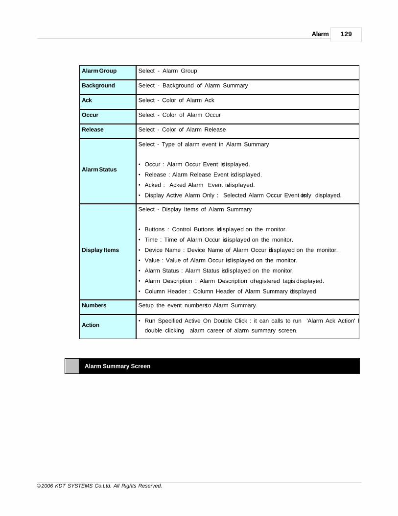
Alarm 129
© 2006 KDT SYSTEMS Co.Ltd. All Rights Reserved.
Alarm Group Select - Alarm Group
Background Select - Background of Alarm Summary
Ack Select - Color of Alarm Ack
Occur Select - Color of Alarm Occur
Release Select - Color of Alarm Release
Alarm Status
Select - Type of alarm event in Alarm Summary
· Occur : Alarm Occur Event is displayed.
· Release : Alarm Release Event is displayed.
· Acked : Acked Alarm Event is displayed.
· Display Active Alarm Only : Selected Alarm Occur Event is only displayed.
Display Items
Select - Display Items of Alarm Summary
· Buttons : Control Buttons is displayed on the monitor.
· Time : Time of Alarm Occur is displayed on the monitor.
· Device Name : Device Name of Alarm Occur is displayed on the monitor.
· Value : Value of Alarm Occur is displayed on the monitor.
· Alarm Status : Alarm Status is displayed on the monitor.
· Alarm Description : Alarm Description of registered tag is displayed.
· Column Header : Column Header of Alarm Summary is displayed.
Numbers Setup the event numbers to Alarm Summary.
Action· Run Specified Active On Double Click : it can calls to run 'Alarm Ack Action' by
double clicking alarm career of alarm summary screen.
Alarm Summary Screen

CIMON-Xpanel130
© 2006 KDT SYSTEMS Co.Ltd. All Rights Reserved.
StopA real-time update of the Alarm summary is stopped.The update career of the alarm
summary is only stopped.
Stamp Register an unrelated Stamp event with the state of alarm in the alarm career.
AckChange the chosen events into the condition of the Alarm Ack. There is a change of
the Alarm Ack Color.
Setup"Alarm Summary" is displayed on the monitor. it can change the type of alarm event
and alarm group.
Config "Xpanel Configuration" is displayed on the monitor.
Font Changing of Alarm Summary
· Select - Object of Alarm Summary to change Font
· Click - [View] -> [Font Tool] of Xpanel Designer
· Change - Font Size or Display Type in Font Tool.
Make a Control Button of Alarm List Using Key Type.
· Select - Object to use by Button
· Double click - Object."Object Config" is displayed.
· Click - [Touch] -> [Key Input] of Action

Alarm 131
© 2006 KDT SYSTEMS Co.Ltd. All Rights Reserved.
· Select - Key Type. Click - [Ok]
· Refer to the Key Type.
Button Action Key Type
Stop/Run Tab
Stamp Insert
Ack Space
Setup Home
Move Up Up
Move Down Down
Remove selection list Delete
Initialization of List End
CAUTION
* When two more alarm summaries are registered or the trend monitoring, the data logger, and the key
input window object are registered together, it is possible that the object you don’t want is
operated, so touch and choose the object to control before handling.
* In case of the Alarm Group setting to save to the file, even if you delete the list via 'selection list
Delete'/'initialization of List', the Alarm List is restored when inputting the power.
Print out the alarm list
Print out the alarm list using AlarmPrint()
[Ex] AlarmPrint(1,0,0,20,_ALMPRT_ALL_);
The most recent alarm list of group 1 will be printed with font size 10. Refer to the Script manual.
Print out the alarm list as CSV file
Print out the alarm list using AlarmCSVWr()
[Ex] AlarmCSVWr( 1, ”AlarmLog”, 0, _ALMPRT_ALL_, 0);

CIMON-Xpanel132
© 2006 KDT SYSTEMS Co.Ltd. All Rights Reserved.
The most recent alarm list of group 1 will be printed with AlarmLog_XXXXXXXXXXX.CSV File . Refer to the
Script manual.
Clear Alarm List
Clear Alarm List in the designated alarm group using ClearAlarmLog()
In case of the Alarm Group setting to save to the file, the Alarm List is restored when inputting the power.
The content of the warning summery page is updated if the page is opened again.
[Ex] ClearAlarmLog(1);
All alarm list of alarm group 1 will be cleared. Refer to the Script manual.

Top Level IntroThis page is printed before anew top-level chapter starts
Part
XI

CIMON-Xpanel134
© 2006 KDT SYSTEMS Co.Ltd. All Rights Reserved.
11 Graphic Page Editor
The graphic page editor of XpanelDesigner provides easy and simple screen editing environment as followings.
· Provides easy and simple object based editing environment
· Provides various wizard library objects : ready to use button, lamp and switch objects
· Object window makes it possible to explore all the graphic objects with a tree view list.
· Provides the graphic page security system.
· Provides various trend functions.
· Various graphic processing speed optimization options.
The screen size of graphic page can be induced from the model code. The table below lists the screen size of
each model.
Model Screen Size Color Specification
XT04C 480 x 272 TFT, 160,000 Colors
XT05M 320 x 240 Mono STN, Black and White, 16 Grays
XT05S 320 x 240 CSTN, 256 Colors
XT06C 640 x 480 TFT, 65,535 Colors
XT07C 800 x 480 TFT, 65,535 Colors
XT10C 800 x 600 TFT, 65,535 Colors
XT12C 800 x 600 TFT, 65,535 Colors
When a new project is created, one of the model codes above should be specified via following dialog box.
According to this configuration,
the XpanelDesigner decides the page size when a new page file is created.

Graphic Page Editor 135
© 2006 KDT SYSTEMS Co.Ltd. All Rights Reserved.
데이터베이스 설명
· Page Properties
· Frame Editor
· Library
· Object Properties
11.1 Page Properties
Every graphic page has its properties such as background color, position in screen and so on.
Those properties are configured via ‘Page Properties’ dialog box.
This dialog box can be opened by clicking the right button and “Page Setup” menu as shown in following picture.
Page Property

CIMON-Xpanel136
© 2006 KDT SYSTEMS Co.Ltd. All Rights Reserved.
Description Fill in the description of current graphic page.
Popup Page
If this option was checked, the page will be opened in front of previous screen page at
runtime. Otherwise, without this option checking, the previous opened page will be
replaced with this page.
Fixed
Background
This option provides faster graphic processing speed by maintaining another copy of
background image in display memory. All the control-less objects are included in this
background image, and only the controlled objects will be redrawn at every data
updates in run time. If this option was not checked, all the objects would be redrawn at
every new data updates in runtime. This will give a big burden to Xpanel performance if
there are many graphic objects in page.
However, this option has a side-effect. All objects in Xpanel graphic page have their
depth level. Which object will be drawn first at runtime is decided by the depth level.
But, this option can change the depth levels between the objects with and without
control. This phenomenon can be easily shown at run time, especially for the
overlapped objects.
Using 256
Bitmap
Xpanel supports 64K colored bitmap objects. But, these objects consume so much
memory and disk space. This option converts the 64K colored bitmap to 256 colored
automatically. It is very useful when there is not enough disk space or memory. And
also it can be helpful to increase the graphic processing speed at run time.
Draw Changed
Object Only
This option can be used when there is need to get faster graphic processing speed at
run time. When this option was checked, only the object whose value or status was
changed will be redrawn.
However, this option has a side-effect too. When a controlled object was redrawn, the

Graphic Page Editor 137
© 2006 KDT SYSTEMS Co.Ltd. All Rights Reserved.
depth level of the object will be ignored. The controlled object whose status was
changed will be the top most depth and other overlapping objects will not be redrawn.
This phenomenon can be easily shown at run time, especially between the overlapped
controlled objects.
Display Touch
AreaThis option can be used to show touch area. When this option was checked, drawrectangle on touch area at screen touch.
Enable Multi TouchAction
This option can be used when there is need to run many touch action at one time. When this option was checked, all touch actions that was wrapt over will be run atscreen touch.
Sec. Level
A graphic page can be assigned a security level between 0 and 10. Only the user who
has the same or higher security level can open and see the graphic page. (zero is the
lowest security level) Please refer to the section of ‘Security’ for more information about
security system.
Background Designate a background color of this page.
NOTE
To avoid the side effects of “Fixed Background” and “Draw Changed Object Only” options, please
follow the recommendations listed below.
· Do not overlap two or more animated objects.
· Put the animated object to the up-most position in the list of objects, if possible.
· When the “Draw Changed Object Only” option was checked, it is strongly recommended to check the
“Fixed Background” option together.
Page Position

CIMON-Xpanel138
© 2006 KDT SYSTEMS Co.Ltd. All Rights Reserved.
'Edit Position'
Group
The new position and screen size can be specified via these fields. After fill in each
position and size of ‘Edit Position’ group, the ‘Copy’ button applies the new settings to
the actual position.
'Run Position'
Group
This group presents the current screen position and size.
The ‘Copy’ button will change these values to the new configuration as specified in ‘Edit
Position’ group.
Position In
Frame
If current editing page is a element of a frame, specify the actual position in frame.
One of four possible positions can be chosen. The frame will be described more
precisely in next section.
Action
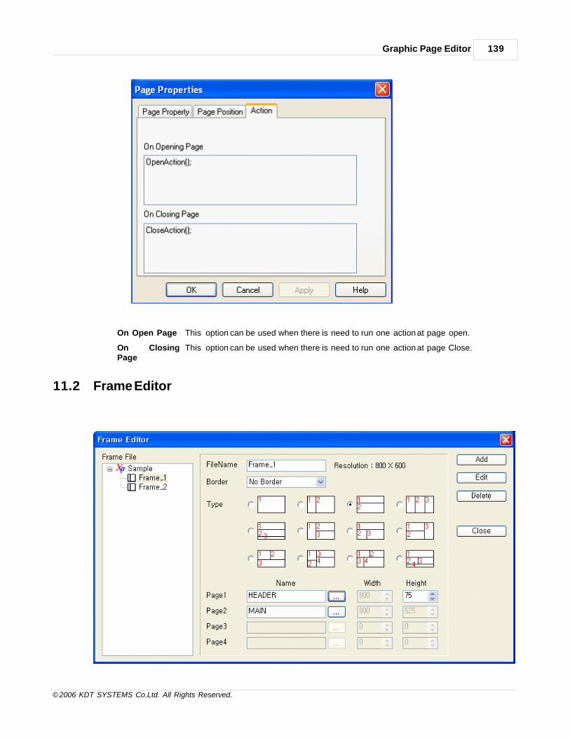
Graphic Page Editor 139
© 2006 KDT SYSTEMS Co.Ltd. All Rights Reserved.
On Open Page This option can be used when there is need to run one action at page open.
On ClosingPage
This option can be used when there is need to run one action at page Close.
11.2 Frame Editor

CIMON-Xpanel140
© 2006 KDT SYSTEMS Co.Ltd. All Rights Reserved.
The frame function is a means to display multiple pages at the same time in a screen.
This function removes repeated and boring tasks from the graphic page designing. The frame editor is
activated through the menu ‘File’-‘Frame Editor’.
XPanelDesigner provides 12 styles of predefined multiple page layouts as shown in the above picture.
In this dialog box, the frame can be created, modified and deleted from current project. A frame includes
several pages for its layout elements.
The size and initial pages for each layout element are configured in this dialog box.
Note that the ‘Position in Frame’ property of each initial page should be matched with the assigned page
number (Page1 .. Page4).
Frame as a starting page
The frame file (.FRX) can be chosen as a starting page as shown in the above picture.
Open a new frame with touch
Following example picture shows the situation of giving a touch operation to a graphic object.
According to this example, touch action is given as “Open Page” and the frame name is given as a ‘Page
Name’. This example will work without any problem.
The touch operation processor can distinguish the name of page and frame.

Graphic Page Editor 141
© 2006 KDT SYSTEMS Co.Ltd. All Rights Reserved.
Open a new frame with command expression
The “FrameOpen()” function is provided for opening a new frame. Refer to the ‘Script’ section for more
information about ‘FrameOpen()’ function.

CIMON-Xpanel142
© 2006 KDT SYSTEMS Co.Ltd. All Rights Reserved.
Replace a page in frame
When a frame is opened, the pages opened with the frame are replaced by ”PageOpen()” function.
Refer to the ‘Script’ section for more information about the ‘PageOpen()’ function.
Every page is given a ‘Position in Frame’ property as shown in the above configuration dialog box. When a

Graphic Page Editor 143
© 2006 KDT SYSTEMS Co.Ltd. All Rights Reserved.
page is
opened by ‘PageOpen()’ function or other ways, this property decides the page which will be replaced by the
new one.
The page which has the same position number with the new page designated in ‘PageOpen()’ function is
replaced.
However, if the new page has no position number (set as ‘None’), the entire frame will be closed and only
the new page
will be opened and displayed in the screen.
Frame closing conditions
A frame is closed at following conditions.
1) When a page without position number is opened.
2) When other new frame is opened by touch operation or function such as ‘FrameOpen()’.
11.3 Library
In XpanelDesigner, there are two different types of library objects.
One is called ‘Wizard Object’ and the other is ‘Library Object’. The difference between these two types of
objects is whether the object properties are given or not.
The wizard objects are marked with “(w)” string in front of their names as shown in the following picture.

CIMON-Xpanel144
© 2006 KDT SYSTEMS Co.Ltd. All Rights Reserved.
SEE :
· Wizard Object
· User Library
11.3.1 Wizard Object
Each wizard object has its own configuration dialog box. In this section, all the configuration dialog boxes of
wizards are explained.
IN THIS TOPIC :
BitLamp
Color
TagVal
BitSwitch1
BitSwitch2
TagWrite
DataEntry
MomentWrite
Command
HoriSize
VertSize
Keyinput
KeyInput2
OpenPage
ClosePage
BitLamp
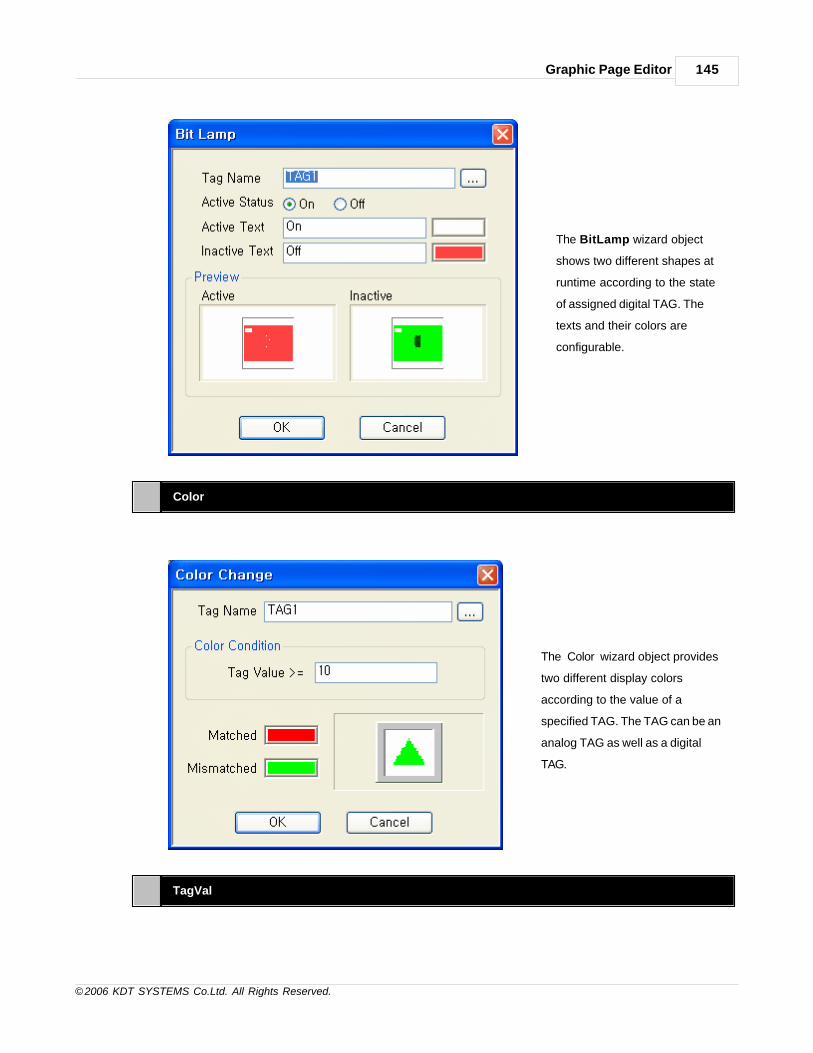
Graphic Page Editor 145
© 2006 KDT SYSTEMS Co.Ltd. All Rights Reserved.
The BitLamp wizard object
shows two different shapes at
runtime according to the state
of assigned digital TAG. The
texts and their colors are
configurable.
Color
The ‘Color’ wizard object provides
two different display colors
according to the value of a
specified TAG. The TAG can be an
analog TAG as well as a digital
TAG.
TagVal

CIMON-Xpanel146
© 2006 KDT SYSTEMS Co.Ltd. All Rights Reserved.
The ‘TagVal’ wizard object
displays the value of specified
TAG. The colors of background
and value text are kept as
option. One of six available
formats can be chosen as display
format. All the available formats
are explained in the following
table.
Format Description
????
Display format will be automatically decided according to the data type of TAG.
If the data type of TAG is ‘Float’, then ‘####.0000’ format will be applied automatically.
Otherwise, ‘# # # #’ format is applied.
# # # # Decimal integer value display format or string tag value.
# # # # . 0 Floating point value display format with 1 significant digit.
# # # # . 0 0 Floating point value display format with 2 significant digits.
#### .000 Floating point value display format with 3 significant digits.
####.0000 Floating point value display format with 4 significant digits.
BitSwitch1

Graphic Page Editor 147
© 2006 KDT SYSTEMS Co.Ltd. All Rights Reserved.
The BitSwitch1 wizard object
shows two different shapes at
runtime according to the state of
assigned digital TAG. And also,
this object provides touch
operation controlling function.
When this object is touched at
runtime, the state specified
digital TAG will be changed via
one of three control types (set,
reset or toggle).
If the ‘Enable Condition’ check
box is checked, a conditional
expression can be declared. The
evaluated value of this
expression enables or disables
the controlling function. If the
evaluated value is false, then the
controlling function will be
disabled. For more information
about conditional expression,
refer to the section of ‘Script’.
BitSwitch2
The BitSwitch2 wizard object shows two different shapes at runtime according to the state of assigned
digital TAG.
And also, this object provides touch operation controlling function. When this object is touched at runtime,
the state specified digital TAG will be toggled.
There are two differences between BitSwitch1 and BitSwitch2 wizard object. The BitSwitch2 object provides
text configuration function,
but it allows only one type of TAG control, toggling.

CIMON-Xpanel148
© 2006 KDT SYSTEMS Co.Ltd. All Rights Reserved.
If the ‘Enable Condition’
check box is checked, a
conditional expression can be
declared. The evaluated value of
this expression enables or
disables the controlling function.
If the evaluated value is false,
then the controlling function will
be disabled. For more
information about conditional
expression, refer to the section
of ‘Script’.
TagWrite
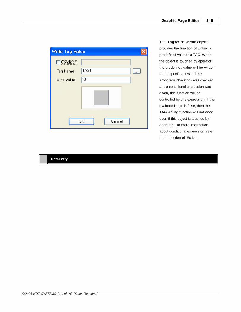
Graphic Page Editor 149
© 2006 KDT SYSTEMS Co.Ltd. All Rights Reserved.
The ‘TagWrite’ wizard object
provides the function of writing a
predefined value to a TAG. When
the object is touched by operator,
the predefined value will be written
to the specified TAG. If the
‘Condition’ check box was checked
and a conditional expression was
given, this function will be
controlled by this expression. If the
evaluated logic is false, then the
TAG writing function will not work
even if this object is touched by
operator. For more information
about conditional expression, refer
to the section of ‘Script’.
DataEntry

CIMON-Xpanel150
© 2006 KDT SYSTEMS Co.Ltd. All Rights Reserved.
The ‘DataEntry’ wizard object
provides a touch button
function which gets number
input from operator. Input
number will be applied to the
specified TAG. And also, input
range checking function
applicable to the input value.
Following three sample pictures show the available keypad window style. The size of keypad window is
different between each window style.
Window Style 1 Window Style 2 Window Style 3

Graphic Page Editor 151
© 2006 KDT SYSTEMS Co.Ltd. All Rights Reserved.
MomentWrite
The ‘MomentWrite’ wizard object
provides a momentary push button
function. When the button is
pushed, a value specified as ‘When
Pushed’ is written to the device
memory. And next, when the
button is released, another value
specified as ‘When Released’ is
written to the device memory
again.
This object can be controlled by a
logical value from conditional
expression, by checking the
‘Enable Condition’ check box. If the
calculated logic of conditional
expression is false, this object does
not issue the control values even if
it was touched by operator. Refer
to the section of ‘Script’ for more
information about the conditional
expression.
Command

CIMON-Xpanel152
© 2006 KDT SYSTEMS Co.Ltd. All Rights Reserved.
The ‘Command’ wizard runs the programmed
command script when it was touched by operator.
This function can be filtered by the conditional
expression. The conditional expression can be
declared by checking the ‘Enable Condition’
check box. If the evaluated value of this
conditional expression is false, then the command
script will not be executed. For more information
about the command script and conditional
expression, refer to the section of ‘Script’.
HoriSize
The ‘HoriSize’ wizard object
provides a variable sized bar
function (bar graph). This object
is a horizontal bar styled graph,
and one of three origin (base)
position can be chosen (leftmost,
middle, rightmost).
VertSize
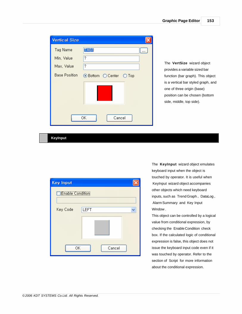
Graphic Page Editor 153
© 2006 KDT SYSTEMS Co.Ltd. All Rights Reserved.
The ‘VertSize’ wizard object
provides a variable sized bar
function (bar graph). This object
is a vertical bar styled graph, and
one of three origin (base)
position can be chosen (bottom
side, middle, top side).
KeyInput
The ‘KeyInput’ wizard object emulates
keyboard input when the object is
touched by operator. It is useful when
‘KeyInput’ wizard object accompanies
other objects which need keyboard
inputs, such as ‘Trend Graph’, ‘DataLog’,
‘Alarm Summary’ and ‘Key Input
Window’.
This object can be controlled by a logical
value from conditional expression, by
checking the ‘Enable Condition’ check
box. If the calculated logic of conditional
expression is false, this object does not
issue the keyboard input code even if it
was touched by operator. Refer to the
section of ‘Script’ for more information
about the conditional expression.

CIMON-Xpanel154
© 2006 KDT SYSTEMS Co.Ltd. All Rights Reserved.
KeyInput2
The ‘KeyInput2’ wizard object emulates
keyboard input when the object is
touched by operator. This object is an
enhanced version of ‘KeyInput’ wizard
object. ‘KeyInput2’ wizard object displays
the symbol character of specified key
code and provides the selectable color
option. It is useful when ‘KeyInput2’
wizard object accompanies other objects
which need keyboard inputs, such as
‘Trend Graph’, ‘DataLog’, ‘Alarm
Summary’ and ‘Key Input Window’.
This object can be controlled by a logical
value from conditional expression, by
checking the ‘Enable Condition’ check
box. If the calculated logic of conditional
expression is false, this object does not
issue the keyboard input code even if it
was touched by operator. Refer to the
section of ‘Script’ for more information
about the conditional expression.
OpenPage
The ‘OpenPage’ wizard object provides the opening function of a screen page when it is touched by
operator.
The name of page to be opened by this object should be specified.

Graphic Page Editor 155
© 2006 KDT SYSTEMS Co.Ltd. All Rights Reserved.
If the ‘Condition’ check box is
checked, a conditional expression
can be declared. The evaluated logic
of this expression at runtime enables
or disables the function of this
object. If the evaluated logic is false,
then page opening function will not
work even if this object is touched by
operator. For more information about
conditional expression, refer to the
section of ‘Script’.
ClosePage
The ‘ClosePage’ wizard object
provides the screen page closing
function when it is touched by
operator. The name of page to be
closed by this object should be
specified.
If the ‘Condition’ check box is
checked, a conditional expression
can be declared. The evaluated value
of this expression at runtime enables
or disables the function of this
object. If the evaluated value is false,
then page closing function will not
work even if this object is touched by
operator. For more information about
conditional expression, refer to the
section of ‘Script’.
11.3.2 User Library
Besides the provided library objects, user created graphic objects can be registered in the library.

CIMON-Xpanel156
© 2006 KDT SYSTEMS Co.Ltd. All Rights Reserved.
Add a New Object to Library
1. Create a graphic object. And make the object as selected state as shown in the example below.
2. Open the library manipulating window. Follow the menu ‘Tools’-‘User Library Edit’.
3.Give a group name and object name of created object. If the group name is not registered before, a new
group with given name will be created automatically.
If the object name is the same name with existing object in library, this library object will
be replaced with the new one.

Graphic Page Editor 157
© 2006 KDT SYSTEMS Co.Ltd. All Rights Reserved.
4. The ‘Add’ button of above dialog box will register the new object to library.
Open the library window and check the result as shown in the following picture.
Delete an Object from Library

CIMON-Xpanel158
© 2006 KDT SYSTEMS Co.Ltd. All Rights Reserved.
1. Open the library manipulating window without any object selection. (‘Tools’-‘User Library Edit’ menu)
Then, the library manipulating window will be shown with ‘Delete’ button as shown in the following
example.
2. The object to be deleted can be found by using the ‘Group Name’ and ‘Object Name’ combo box.
If the object was found, press the ‘Delete’ button to remove the object from library.
11.4 Object Properties
XPanel page is a dynamic screen based on graphic objects. Every graphic object in page has its own properties.
Some of properties are static properties such as color, line style, line width and so on.
And some other properties are dynamic properties such as animation style, control type etc.
XPanelDesigner provides a integrated configuration window for setting up such kind of various properties of
graphic objects.
A configuration window example is presented below.

Graphic Page Editor 159
© 2006 KDT SYSTEMS Co.Ltd. All Rights Reserved.
See
Style
Visble
Blink
V-Size
H-Size
V-Move
H-Move
Color
Touch
Entry Data

CIMON-Xpanel160
© 2006 KDT SYSTEMS Co.Ltd. All Rights Reserved.
11.4.1 Style
All the static graphic properties can be configured in this page. Object’s position, size, color, fill pattern, fill color
etc. are the configurable properties.
Note that the upper-left corner of screen and object are the origin of position coordinate.

Graphic Page Editor 161
© 2006 KDT SYSTEMS Co.Ltd. All Rights Reserved.
11.4.2 Visible
The ‘Visible’ property makes the object visible or not, according to the specified TAG’s value.
Typically a digital TAG is used to control the visibility of the object.

CIMON-Xpanel162
© 2006 KDT SYSTEMS Co.Ltd. All Rights Reserved.
11.4.3 Blink
The ‘Blink’ property makes the object to blink when the TAG value is the given state.
The blinking speed is adjustable in the unit of 100mSec.
11.4.4 V-Size

Graphic Page Editor 163
© 2006 KDT SYSTEMS Co.Ltd. All Rights Reserved.
The ‘V-Size’ property varies the height of the object depending on the value of specified TAG.
If TAG value is equal to the designated minimum value, the height of object will be 0.
And if TAG value is equal to the designated maximum value, then the height of object will be original height.
(Original height is the drawn height.)
11.4.5 H-Size

CIMON-Xpanel164
© 2006 KDT SYSTEMS Co.Ltd. All Rights Reserved.
The ‘H-Size’ property varies the width of the object depending on the value of specified TAG.
If TAG value is equal to the designated minimum value, the width of object will be 0.
And if TAG value is equal to the designated maximum value, then the width of object will be original width.
(Original width is the drawn width.)
11.4.6 V-Move

Graphic Page Editor 165
© 2006 KDT SYSTEMS Co.Ltd. All Rights Reserved.
The ‘V-Move’ property moves the object depending on the value of specified TAG.
If TAG value is equal to the designated minimum value, the position of the object will be originally drawn
position.
And if TAG value is equal to the designated maximum value, then the position will be moved with the amount
of pixel value assigned to
the ‘Move’ field. If the ‘Bottom’ was checked as the base position, the movement direction will be upward.
Otherwise (‘Top’), the movement direction will be downward.
11.4.7 H-Move
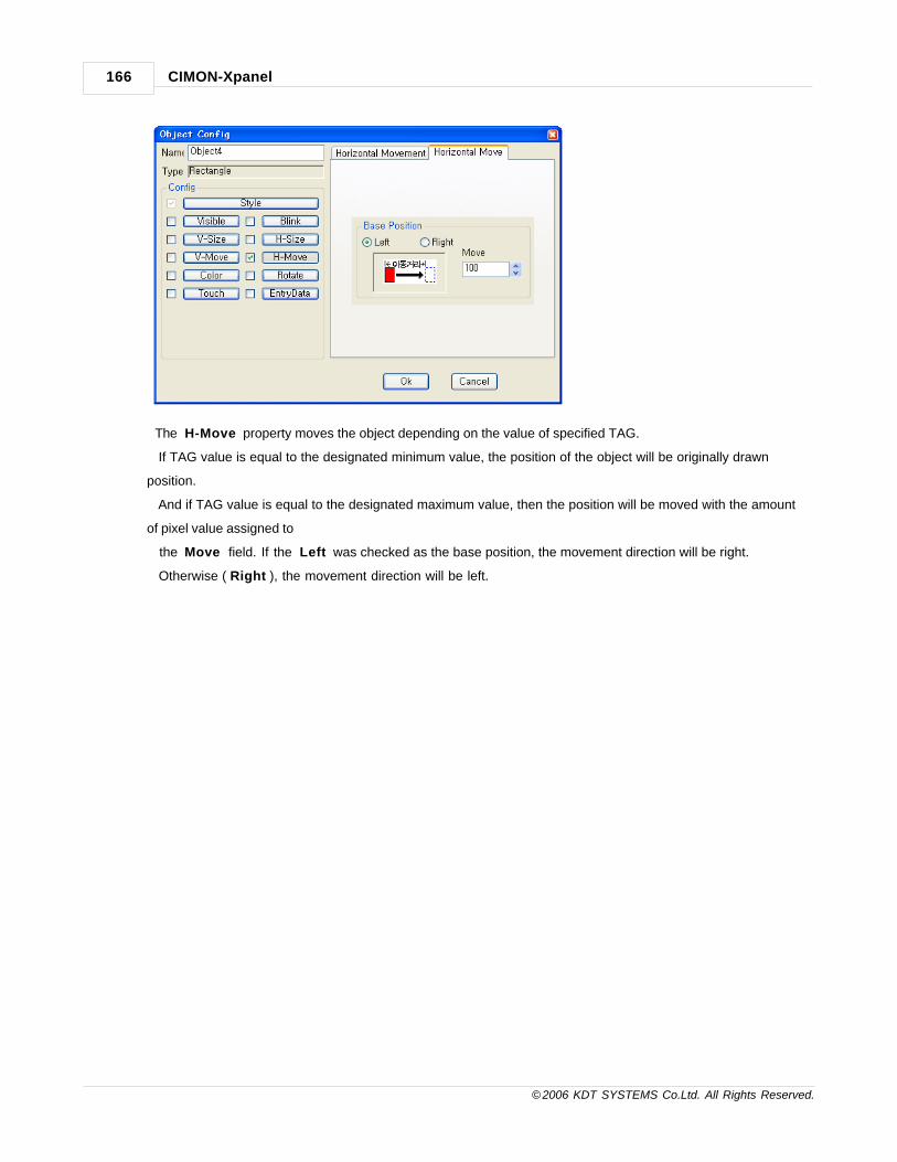
CIMON-Xpanel166
© 2006 KDT SYSTEMS Co.Ltd. All Rights Reserved.
The ‘H-Move’ property moves the object depending on the value of specified TAG.
If TAG value is equal to the designated minimum value, the position of the object will be originally drawn
position.
And if TAG value is equal to the designated maximum value, then the position will be moved with the amount
of pixel value assigned to
the ‘Move’ field. If the ‘Left’ was checked as the base position, the movement direction will be right.
Otherwise (‘Right’), the movement direction will be left.

Graphic Page Editor 167
© 2006 KDT SYSTEMS Co.Ltd. All Rights Reserved.
11.4.8 Color
The ‘Color’ property changes the fill color of object depending on the value of specified TAG.
Maximum 8 different color boundary values can be declared.
This means that there can be maximum 9 different colors including the original color of object.
11.4.9 Rotate

CIMON-Xpanel168
© 2006 KDT SYSTEMS Co.Ltd. All Rights Reserved.
The ‘Rotate’ property rotates the object depending on the value of specified TAG.
The rotate direction and angle and center position are configurable parameters.
The center point can be easily calculated with the coordinate information in ‘Style’ properties (static properties)
.
For example, assume a following object’s coordinate data in ‘Style’ property page.
This object’s center point is :
Xcent = X + Width / 2 =
141 + 312 / 2 = 297
Ycent = Y + Height / 2 =
30 + 33 / 2 = 46.5 = 46

Graphic Page Editor 169
© 2006 KDT SYSTEMS Co.Ltd. All Rights Reserved.
11.4.10Touch
The ‘Touch’ property creates an operator touch zone. Following table shows the list of available actions with
the ‘Touch’ property.
Action Description Configuration Items
Open Page Open a new page specified in below.
Close Page Close the specified page
Write Tag ValueWrite the specified value to the specifiedTAG.

CIMON-Xpanel170
© 2006 KDT SYSTEMS Co.Ltd. All Rights Reserved.
Write Digital ValueControl the digital TAG with one of threeavailable control types.
Write MomentaryWrite two different values in series to thespecified TAG. One value at touch downand the other value at touch release.
Command Expression
Execute the programmed commandexpression. Refer to the ‘Script’ section formore information about the commandexpression.
Key InputIssue the specified key code at touch. Thisaction emulates the keyboard input.
If the ‘Condition’ check box above is checked, a conditional expression can be declared.
The evaluated value of this expression at runtime enables or disables the function of this property.
If the evaluated value is false, then the defined action will not work even if the touch zone is touched by
operator.
For more information about conditional expression, refer to the section of ‘Script’.
Furthermore, the touch zone has its own security level.
The specified action is executed only when the object is touched by the operator who has higher level of
privilege level
than the specified security level. For more information about the security system of XPanel, refer to the
‘Security’ section.

Graphic Page Editor 171
© 2006 KDT SYSTEMS Co.Ltd. All Rights Reserved.
11.4.11EntryData
[ Number Enrty Data ] [ String Enrty Data ]
The ‘EntryData’ property creates an
operator touch area which pops up one
of three different sized number or
string pad. Input data from operator will
be applied to the specified TAG. And
also, input range checking function
applicable to the input value. Following
three sample pictures show the
available number or string pad window
style. The size of number or string pad
window is different between each
window style. (‘Window style 3’ number

CIMON-Xpanel172
© 2006 KDT SYSTEMS Co.Ltd. All Rights Reserved.
pad fits small sized screen well, such
as 320x240 resolution)
[ Position Offset ]
Number Window Style 1 Number Window Style 2 Number Window Style 3
11.4.12Switch/Lamp
1. Overview
This function can express Switch/Lamp object on the monitor, practice the designated action or check the
condition of tag.
Each function of switch and lamp registered in the page can be used independently or two functions can be used
together by registering same tag.

Graphic Page Editor 173
© 2006 KDT SYSTEMS Co.Ltd. All Rights Reserved.
2. Switch Function
Object Name It is a name of pertinent Switch/Lamp object.
Shape Select "State Image Select" of Switch/Lamp is displayed.
Shape nil
Switch/lamp will be displayed on the page as a transparent state like the area(size) of
switch/lamp.
A pertinent area is displayed in the dotted line.
Touch - Down / Touch- Up
The operation point of the function registered in a pertinent switch can be confirmed.
It is possible to add the new function and delete an existing function.
Function SelectionTab
Select - Switch / Switch Common / Lamp / Label Function
Switch FunctionSelection Buttons
Select - Switch according to each function. The screen above is a Bit Switch selection
screen.
1) Bit Switch

CIMON-Xpanel174
© 2006 KDT SYSTEMS Co.Ltd. All Rights Reserved.
Tag Name Input - Tag Name to the Bit Switch
Function
Select - Function of Bit Switch
· Set : The specified tag enters the state of turning on if the switch is pushed. The
state is maintained.
· Reset : The specified tag enters the state of turning off if the switch is pushed. The
state is maintained.
· Toggle : The specified tag changes into the state of ON/OFF if the switch is
pushed.
Momentary This function is registered to the Special Function Switch.
2) Word Switch

Graphic Page Editor 175
© 2006 KDT SYSTEMS Co.Ltd. All Rights Reserved.
Switch Function
Select - Switch Function of Word Switch
- Write Analog Value : The value that the user set to the specified tag can be input.
- Tag Operation :When acting switch, the Operation action to the specified tag can
be specified.
Operation that can be specified : +, -, AND, OR, XOR
Value
You can input the value of the tag registered in analogue switch and it is supported
with the data input of two shapes of 10/16 essence. Only if the switch action is the tag
Operation, the tag can be used.
HexaThe form of the input value can be specified. If it is not a check, it will basically
recognize it by the value of the decimal number.
Operator
When Tag Operation is selected in the Switch Function, Operation Function can be
used.
Operation that can be specified : +, -, AND, OR, XOR
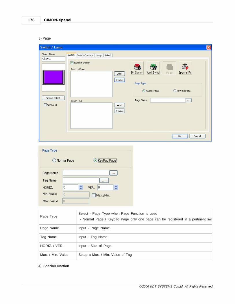
CIMON-Xpanel176
© 2006 KDT SYSTEMS Co.Ltd. All Rights Reserved.
3) Page
Page TypeSelect - Page Type when Page Function is used
- Normal Page / Keypad Page only one page can be registered in a pertinent switch.
Page Name Input - Page Name
Tag Name Input - Tag Name
HORIZ. / VER. Input - Size of Page
Max. / Min. Value Setup a Max. / Min. Value of Tag
4) Special Function

Graphic Page Editor 177
© 2006 KDT SYSTEMS Co.Ltd. All Rights Reserved.
Switch Action
Command : Command that can be used with Xpanel Designer can be input.
Key Input : Set the Keyboard Input Function to Switch.
Write the Value of Momentary : It is a Momentary input function.
Key Value Select - Key Value. The same input as the input with a general keyboard is possible.
Down - Input Value When acting switch, set the Input Value in the condition that Switch Downs.
Up - Input Value When acting switch, set the Input Value in the condition that Switch Ups.
3. Switch Common

CIMON-Xpanel178
© 2006 KDT SYSTEMS Co.Ltd. All Rights Reserved.
Use TouchSet the Touch Condition. When the relative terms are satisfied, the touch action of
switch is possible.
Touch Condition
SettingInput - Touch Condition
Use Security Function Check - Use Security Function
Security Setting Set the Security Level. The highest level is ten for the security level.
4. Lamp

Graphic Page Editor 179
© 2006 KDT SYSTEMS Co.Ltd. All Rights Reserved.
Use Lamp Set - "Use Lamp".
Tag TypeSet - "Tag Type" of Lamp .
The string tag cannot be selected.
State
Ranges of the number of states are different because of the kind of pertinent tag and
the union of the state conversion condition.
Digital Tag Analog Tag
At each Bit condition
conversion2 - 5 2-17
With Data condition
conversion2-16 2-256
Tag RegistrationBecause the activated State is changed by the number of each State, register tags
after setting the number of the State.
5. Label
- The pertinent label could be expressed to each switch / lamp object.
- Label can express the registered string to the "direct input" and the "string table".
- "Font Set" can be set to each label.

CIMON-Xpanel180
© 2006 KDT SYSTEMS Co.Ltd. All Rights Reserved.
Sate Select The "Sate Select" is activated based on the number of states set to the lamp.
Input Type Select - "Direct Input" or "String Table".
Direct InputThe user can make the content directly by being activated when the "Direct Input" is
selected.
String Table Set When the string table is selected, a pertinent string can be set.
Font Set "Font Set" can set the size, the color, and the alignment of the displayed string.
6. Image Setting of Switch/Lamp

Graphic Page Editor 181
© 2006 KDT SYSTEMS Co.Ltd. All Rights Reserved.
1) Click - [Shape Select]
Part Palette The image library registered now is displayed.
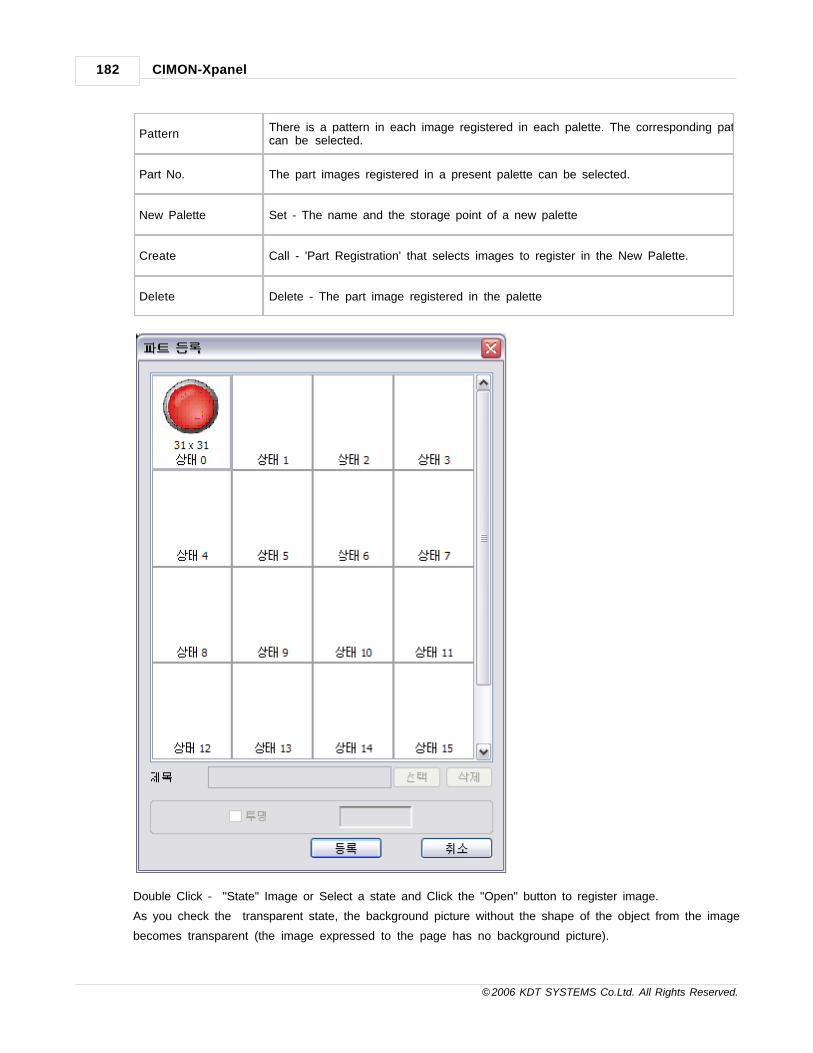
CIMON-Xpanel182
© 2006 KDT SYSTEMS Co.Ltd. All Rights Reserved.
PatternThere is a pattern in each image registered in each palette. The corresponding patterncan be selected.
Part No. The part images registered in a present palette can be selected.
New Palette Set - The name and the storage point of a new palette
Create Call - 'Part Registration' that selects images to register in the New Palette.
Delete Delete - The part image registered in the palette
Double Click - "State" Image or Select a state and Click the "Open" button to register image.
As you check the transparent state, the background picture without the shape of the object from the image
becomes transparent (the image expressed to the page has no background picture).

Graphic Page Editor 183
© 2006 KDT SYSTEMS Co.Ltd. All Rights Reserved.

Top Level IntroThis page is printed before anew top-level chapter starts
Part
XII

Keypad Page 185
© 2006 KDT SYSTEMS Co.Ltd. All Rights Reserved.
12 Keypad Page
By using the function, you can use the page designed by the operator as the keypad for the data input.
See :
· Make Keypad Page
12.1 Make Keypad Page
Make Keypad Page
Make KeypadPage
Following picture shows how to create "Keypad Page".
*The keypad page should satisfy the following condition.
Select - "Keypad Page" in Page Properties
It should include ‘Keypad input window’ one more and be smaller than the picture’s
size in the setup.
Create - New Page and Set - "Keypad Page" in Page Properties
Change - The size of page in Page Position and Click - [->Copy]

CIMON-Xpanel186
© 2006 KDT SYSTEMS Co.Ltd. All Rights Reserved.
Register - "Key Input Window"
•In the registration of the keypad input window, the designated tag is ignored when it is
operated by the keypad. Instead of it, ‘Command On Input’ is normally handled.
•When it is operated by the keypad, all key input windows registered to the page hand the
input figure to the tag registered to ‘Open the keypad page’ lastly called. If registered tag
is the number (analogue, digital) tag and the inputted content in the key input window is
not able to express numerically, the writing action will be ignored.
Register - "Key Input" button to input the value in "Key Input Window"

Keypad Page 187
© 2006 KDT SYSTEMS Co.Ltd. All Rights Reserved.
Save the Page.
Using KeypadPage
Following picture shows how to use "Keypad Page".
Open - Page to call "Keypad Page" and "Object Config" to use by button.
Select - "Touch" function and Set - "Keypad Page Open" in the Print Page of Action
Register - "Tag Name" to input the value from the keypad page
Input - HORIZ. and VER. for position of keypad page
If Maximum/Minimum Value of input are applied, set up the range of Maximum/Minimum
Value.
Register - Keypad Page to "Page Name"
•If the registered page is normal and popup page, 'Action' will be "Open Page".
•As the keypad page is already opened, the page is moved to the designated position.

Top Level IntroThis page is printed before anew top-level chapter starts
Part
XIII

Key Input Window 189
© 2006 KDT SYSTEMS Co.Ltd. All Rights Reserved.
13 Key Input Window
The Keyboard-Input is expressed to the monitor and stored with a designated tag.
It utilizes to manage a bar code input and to compose the screen of a password log-in.
See :
· Key Input Setting
13.1 Key Input Setting
Click - [Draw] -> [Key Input Window] of Xpanel Designer

CIMON-Xpanel190
© 2006 KDT SYSTEMS Co.Ltd. All Rights Reserved.
End-Code Save inputted contents after inputting the value of a designated key at the tag.
Input Tag Name Select - String Tag to save the input contents.
Command On
Input
Input - "Command"
The Command inputted here is operated after obtaining the input complete code
and storing the input content to the designated tag.
[Ex.] [When the input value is 1234, the "Main" page is opened.] Write the following
command.
IF(BARCODE_00 == “1234”)
PageOpen(“Main”) ;
Max. Input Set the length of the Max. String expressed to the key input window.

Key Input Window 191
© 2006 KDT SYSTEMS Co.Ltd. All Rights Reserved.
Characters Not to express the String over the designated length on the input window.
Max. / Min ValueIf Analog Tag is selected, Set - "Max. / Min. Value". This setting is disregarded in
the string tag.
Min. Value Set - Input Min. Value
Max. Value Set - Input Max. Value
Clear Window At
Overflow
If this setting is checked, remove the last content and then express the new
content.
End-Code Process The state of the key input widow is changed referring to the setting of "End-Code".
Remove Input
FocusRemove Input Focus of key input widow. The string is not input any more.
Move Focus To
Next Input Window
Other key input windows are automatically selected. The selection of key input
window that input completes is canceled.
Clear Window
Clear - Content of key input window
After checking and obtaining the input complete code, save the tag’s value and
remove the content expressed to the present key input window.
If the check is canceled, the tag’s value will be saved and the last input content is
displayed before obtaining next key input.
Password Type The string is displayed in the key input window by “***" form if checked.
Show Keyboard
On Double Click
Show Keyboard On Double Click 'Key Input Window'
It will disappear when a soft keyboard is displayed.
CAUTION
If two more key input windows are registered in the one screen, the key input is applied to only the one
window that is activated.
So, in case of using the key input with other Objects, the control of the key input of other Objects are not
handled normally.

Top Level IntroThis page is printed before anew top-level chapter starts
Part
XIV

Data Logging 193
© 2006 KDT SYSTEMS Co.Ltd. All Rights Reserved.
14 Data Logging
This function is used to save the tag value for logging in file type.
The tags for logging are analog and digital tag. Only the tags selected for data logging when tags are registered
to a database are available.
For logging tag values, a data-logging model should be set up and be registered to a project.
According to selected model, the data of a corresponding tag are logged and saved in file type.
The logged tag data is used as the data for a trend.
· The function to save a logged data in file is provided.
· Data are logged according to regular interval or in case that a value is changed.
· Files that are classified according to file size and logging term are saved.
· Back-up function, which is used to save logged data file to other location automatically, is provided.
· A specific data saved in a file can be read through Script language.
· Logged data can be displayed on a trend window through Historical Trend.
See :
· Data Logging Configuration
· Using Data Logging
14.1 Data Logging Configuration
Click - [Tools] -> [Data Logging] of Xpanel Designer

CIMON-Xpanel194
© 2006 KDT SYSTEMS Co.Ltd. All Rights Reserved.
Description of Control Button
Add
If you press the Add button after you configure data logging, a new model will be
added. If a same logging model name exists, an Error dialogue box will appear.
ApplyThis is used to register a corresponding data-logging model. If you press this button,
a registered model will be displayed in the data logging model list on the left.
Delete
This is used to delete a created model. If you press the Delete button after you select the model deleted in a datalogging model list, a Warning dialogue box will appear. If you want to delete,select “Yes”. Otherwise, select “No”.

Data Logging 195
© 2006 KDT SYSTEMS Co.Ltd. All Rights Reserved.
Close
This is used to close a Data Logging Configuration. If you change or add a data-logging model, the dialogue box to ask whethera model is registered will appear.
Configuration of Data Logging
Logging ModelName
This is used to enter the name of the data-logging model created.
The limited conditions
1. It is available to enter in the combination of English, Korean, numeral and
specific characters.
2. There is no limitation on the number of the characters entered.
If you do not enter it, an Error dialog box will appear as follows.
Start Type
Xpanel provides 5 different start types. Each of these is based on period,
command, tag and time.
Whenever a new log task is started, a new block file will be created and the old
task will be stopped and closed automatically.
The name of a block file is automatically generated based on the started time.

CIMON-Xpanel196
© 2006 KDT SYSTEMS Co.Ltd. All Rights Reserved.
Periodic
A log task is started periodically. The period of task invoking is configured in the unit
of minute. During one day, log task is started on every multiple of designated
minute. For example, if the ‘Base Time’ was configured as 1H 30M, the log task
will be invoked on 00:00, 01:30, 03:00, 04:30, ..., 22:30.
This example assumes that ‘Time Offset’ is configured as ‘0’. The ‘time offset’ is a
delay of start. If it is assigned as 10, the log task of previous example will be invoked
on 00:10, 01:40 and so on.
Called (by command)
This type of invoking is triggered by a command. A command can be issued by touch
operation or script program. The command has a following format :
DataLog("ModelName", 1)
Trigger TAG
The log task is triggered by the state change of a TAG. When the value of a TAG
changes from zero to non-zero, the log task will be invoked. The value change from
non-zero to zero does not affect to the log task. Designate the name of TAG in ‘Tag
Name’ field.
Enable TAG
The log task is triggered by the state change of a TAG. When the value of a TAG
changes from zero to non-zero, the log task will be invoked. And when the value
changes from non-zero to zero, the log task will be terminated. That is, the log task
keeps logging only while the value of TAG is non-zero. Designate the name of TAG
in ‘Tag Name’ field.
On Time
The log task is invoked only once in a day. Set the time of log in ‘Base Time’ field.
Log Type
(1)Periodic
Tag values are logged at "Periodic".
In case of logging at "Periodic", input a logging Period by the second.

Data Logging 197
© 2006 KDT SYSTEMS Co.Ltd. All Rights Reserved.
(2)Tag Value
If the value of tag is changed, data is logged.
In case of logging at "Tag Value", input a Name of Tag.
The setting of tag is possible only the tag registered in [Tools] ->
[Database] of Xpanel Designer.
Maximum Log No.
Per Block
Setup - Maximum Log No. Per Block
The setting range is 1~2048, and the Data Logging of the block is closed when
the setting maximum number is exceeded.
Maximum Block
No.
Setup - Maximum Block No.
The setting range is 1~32.
[CAUTION] When the setting Maximum Log No. is exceeded, data is covered
to the data block that became the oldest.
Tags
Register - Log Data
The tag that can be registered is digital tag and analog tag.
The selecting of tag is possible only the tag registered in [Tools] -> [Database]
of Xpanel Designer.
14.2 Using Data Logging
How to Save Logging File
Because the Data Logging file is saved by the XXXX type, the user is not seen.
Therefore, it is necessary to change to the CSV format for which the user can utilize this data. The following
two functions are offered in Xpanel for this.
MakeCsv(S1, R2)
MakeCsvUsb(S1, R2)
For details on Internal Function, refer to the Script manual.
On Screen Display
Click - [Draw] -> [Data Log] of Xpanel Designer

CIMON-Xpanel198
© 2006 KDT SYSTEMS Co.Ltd. All Rights Reserved.
Log Model NameSelect - Log Model Name to display on screen.
Only the model registered by the process of two can be selected.
Text Color,Line
Color,Line TypeSetup - Table type of the Log Model
Column No., Row
No.
Setup - Shape of the table
Column first displays 'Date' and 'Time' of "Display" and the name of tag registered in
the Data Log Model is sequentially displayed.
Row displays the Log Data that corresponds to each tag and when 'Maximum
Value', 'Minimum Value', 'Average Value', and 'Summation Value' of "display" are
selected, the selected display item is displayed by reverse order in the Row of the
end of table.
When the setting Maximum Log No. is exceeded, it is possible to see by moving the
data of table via [Draw] -> [Key Input Window] of Xpanel Designer. Refer to the
"Keypad Page" manual
Date TypeSetup - Date Type when 'Date' is selected in "display".
Date Type provides 'YY/MM/DD', 'DD/MM/YY', 'MM/DD', and 'DD/MM'.
Display Display - Necessary item in six-kind item like 'Date' and 'Time' etc.

Top Level IntroThis page is printed before anew top-level chapter starts
Part
XV

CIMON-Xpanel200
© 2006 KDT SYSTEMS Co.Ltd. All Rights Reserved.
15 Data Bridge
Data bridge of Xpanel makes data synchronization between the communication measures possible.
Data bridge by the designated event sends the data of Source Device to the designated area of Destination
Device.
< Data Bridge data flowchart >
See :
· Edit Data Bridge Model
15.1 Edit Data Bridge Model
Click - [Tools] -> [Data Bridge] of Xpanel Designer

Data Bridge 201
© 2006 KDT SYSTEMS Co.Ltd. All Rights Reserved.
Icon Description
Icon Description
Add Data Bridge Model
Edit Data Bridge Model
Delete Data Bridge Model
Add Data Bridge Tag
Edit Data Bridge Tag
Delete Data Bridge Tag
Basic Setup
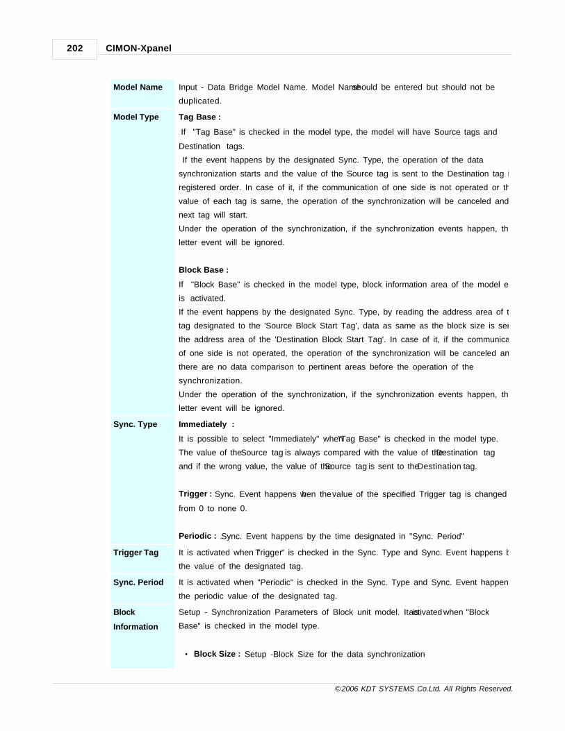
CIMON-Xpanel202
© 2006 KDT SYSTEMS Co.Ltd. All Rights Reserved.
Model Name Input - Data Bridge Model Name. Model Name should be entered but should not be
duplicated.
Model Type Tag Base :
If "Tag Base" is checked in the model type, the model will have Source tags and
Destination tags.
If the event happens by the designated Sync. Type, the operation of the data
synchronization starts and the value of the Source tag is sent to the Destination tag in a
registered order. In case of it, if the communication of one side is not operated or the
value of each tag is same, the operation of the synchronization will be canceled and
next tag will start.
Under the operation of the synchronization, if the synchronization events happen, the
letter event will be ignored.
Block Base :
If "Block Base" is checked in the model type, block information area of the model editor
is activated.
If the event happens by the designated Sync. Type, by reading the address area of the
tag designated to the 'Source Block Start Tag', data as same as the block size is sent to
the address area of the 'Destination Block Start Tag'. In case of it, if the communication
of one side is not operated, the operation of the synchronization will be canceled and
there are no data comparison to pertinent areas before the operation of the
synchronization.
Under the operation of the synchronization, if the synchronization events happen, the
letter event will be ignored.
Sync. Type Immediately :
It is possible to select "Immediately" when "Tag Base" is checked in the model type.
The value of the Source tag is always compared with the value of the Destination tag
and if the wrong value, the value of the Source tag is sent to the Destination tag.
Trigger : Sync. Event happens when the value of the specified Trigger tag is changed
from 0 to none 0.
Periodic : .Sync. Event happens by the time designated in "Sync. Period"
Trigger Tag It is activated when "Trigger" is checked in the Sync. Type and Sync. Event happens by
the value of the designated tag.
Sync. Period It is activated when "Periodic" is checked in the Sync. Type and Sync. Event happens by
the periodic value of the designated tag.
Block
Information
Setup - Synchronization Parameters of Block unit model. It is activated when "Block
Base" is checked in the model type.
· Block Size : Setup -Block Size for the data synchronization

Data Bridge 203
© 2006 KDT SYSTEMS Co.Ltd. All Rights Reserved.
The data of the registered number is sent to the Destination Block.
· Source Block Start : Register - Source Block Start Tag
Real Tag of the device with a consecutive address should
be registered .
· Source Handshake : The value of the tag registered before reading the data of the
Source Block is made as 1,
the value is initialized by 0 after work is completed. It is
used to confirm the Source Data Reception
and Digital Tag should be registered.
· Destination Block Start : Register - Destination Block Start Tag
Real Tag of the device with a consecutive address
should be registered.
· Destination Handshake : The value of the tag registered before writing the data of
the Destination Block is made as 1,
the value is initialized by 0 after work is completed. It
is used to confirm the Destination Data
Transmission and Digital Tag should be registered.

CIMON-Xpanel204
© 2006 KDT SYSTEMS Co.Ltd. All Rights Reserved.
Point
Other communication work to I/O Device will be delayed while synchronization working.
When you use the data bridge function too much or frequently generate the synchronization event,
please note the communication update can be delayed.

Top Level IntroThis page is printed before anew top-level chapter starts
Part
XVI

CIMON-Xpanel206
© 2006 KDT SYSTEMS Co.Ltd. All Rights Reserved.
16 Modbus Slave
1. Function
By the function, the communication can be composed between Master equipment and Xpanel using the Modbus
protocol(RTU, TCP).
Xpanel has memory for Modbus Slave action inside, and if Master asks via the designated communication
channel, it answers to put the content of the memory in the frame.
The Modbus memory is composed of Coil(Max Size: 5000) and the Holding Register(Max Size: 10000) area and
Digital tag can be registered in the Coil area and Analogue/String tag be registered in the Holding Register Area.
· Ex. When Tag1 is registered in Holding Register 400001, If it keeps reading the value of 400001 in Master, the
value of Tag1 is understood and moreover if it keeps writing the value in 400001, the value of Tag1 can be
changed.
Function Contents
1 Coil Area Reading
3 Hold Register Area Reading
5 Coil 단독 Writing
6 Holding Register 단독 Writing

Modbus Slave 207
© 2006 KDT SYSTEMS Co.Ltd. All Rights Reserved.
15 Coil 연속 Writing
16 Holding Register 연속 Writing
< Modbus Function >
If the data form of the registered tag is bigger than Word (UINT 32, INT32, float..) or is the string tag, the
designated number will be used as the beginning number of data.
· Ex 1. When the Form of Tag1 registered in Holding Register 400001 is UINT32, the data of Tag 1 is updated
to 400001 and 400002. When the value is written in 400002 with Master, the value of Tag 1 is also changed.
· Ex 2. When Tag 3 registered in Holding Register 400001 is string tag(string size : 10), the data of Tag 3 is
updated to 400010 ~ 400014. When the value is written in 400014 with Master, the value of Tag 3 is also
changed.
16.1 Modbus Slave Setting
Open Modbus Slave
Click - [Tools] -> [Data Sever] -> [MODBUS Slave] of XpanelDesigner or Modbus Slave item of Project

CIMON-Xpanel208
© 2006 KDT SYSTEMS Co.Ltd. All Rights Reserved.
window.
Communication Setting
The communication channel means a physical passage(Serial, Ethernet) for connection with Master. Setup -
Communication Parameter of the port and the Modbus Unit No. etc. in the channel setting.
The communication channel without the action form is registered up to 3, and each channel can be connected
with one Master.
Communication Setting
Communication Editing
Communication Deletion
· Unit No. is a Modbus Unit No. of Xpanel.
· The communication port should be set not to be duplicated with another communication channel or I/O device.

Modbus Slave 209
© 2006 KDT SYSTEMS Co.Ltd. All Rights Reserved.
· The "Soket No." defined in the Modbus TCP protocol is 502.
· When you register the TCP channel by the addition, The "Soket No." should be set not to be duplicated. In this
case, it is necessary to edit the setting of Master.
Coil Area Tag 등록
· The Coil Area can be registered up to 05000(5000).

CIMON-Xpanel210
© 2006 KDT SYSTEMS Co.Ltd. All Rights Reserved.
· Register - Tag in the Coils Area. If the tag is not registered, the basic value(0) would be answered.
· Click - "Coils Area" in the left window. Register or Edit - Tag using (Registration), (Editing) buttons.
Holding Register Area Tag 등록
· The Holding Register Area can be registered up to 410000(10000).
· Register - Tag in the Holding Register Area. If the tag is not registered, the basic value(0) would be answered.
· Click - "Holding Register Area" in the left window. Register or Edit - Tag using (Registration), (Editing)
buttons.

Top Level IntroThis page is printed before anew top-level chapter starts
Part
XVII

CIMON-Xpanel212
© 2006 KDT SYSTEMS Co.Ltd. All Rights Reserved.
17 Recipe
The recipe service of Xpanel supports the multiple models. This makes it possible to manipulate different recipe
for multiple devices with an Xpanel.
In an Xpanel, every recipe model has its own name, parameters and group data. Up to 1024 group data can be
registered in a recipe model.
But at any time, only one group data can be manipulated in Xpanel. The reason is that a group data must be
located in the memory of Xpanel for manipulation.
A group data can be transferred between four types of media.
And the Xpanel memory is located at the center of these transfers. Following picture shows paths of group data
movement.
Each of group data movement is issued by the internal functions for recipe operation. More precise explanations
can be found on the script section of this manual.
RcpCsvRd(S1, S2,
R3)
A group data can be imported from external memory through CSV formatted file.
CSV formatted file can be created or read by the spreadsheet utilities such as
MS-Excel on PC
RcpMemUp(S1), A group data can be uploaded from the device through communication. For normal

Recipe 213
© 2006 KDT SYSTEMS Co.Ltd. All Rights Reserved.
RcpMemDown(S1) recipe operation,
the communication driver must support the recipe functions.
This can be known from the manual of the communication driver. Refer to the
driver’s manual.
RcpFileStore(S1, R2),
RcpFileRead(S1, R2)
The group data in memory can be stored to the recipe configuration file.
The stored group data will be maintained while power off.
And the function for reading a group data from configuration file is provided also.
RcpUpload(S1, R2) Compounded functions are provided for convenience.
RcpUpload() function is a compounded form of RcpMemUp() and RcpFileStore()
RcpDownload(S1,
R2)
RcpDownload() function is a compounded form of RcpFileRead() and
RcpMemDown().
See :
· Model Configuration
· Recipe Operator Interface
17.1 Model Configuration
A recipe model is defined by following dialog box of Xpanel Designer.

CIMON-Xpanel214
© 2006 KDT SYSTEMS Co.Ltd. All Rights Reserved.
Basic Properties
Mo
del
Na
me
Every recipe model has its own name. This name will be used in the functions for recipe operation.
Nu
mb
er
of
Gr
ou
p
One or more recipe group data can be predefined in a recipe configuration file.
‘Number of Group’ field gets the total number of predefined group data.
These group data can be read or written by RcpFileRead() or RcpFileStore(). Each group is distinguished by the
index number in those functions. According to the following example picture, index 0 is the Vanilla, and index 1 is
Choco and so on.
Re
cip
e
Ar
ea
Sta
rt
Po
siti
on
One of analog TAG in database can be assigned to this field. The device address of the TAG must be designated
with the first address of the recipe data memory area of a device. This memory area must be continuous. The
analog TAG of this field specifies not only the first address but also specifies the type of data. Xpanel supports
WORD (16 bits) and DWORD (32 bits) type of data for recipe. Therefore, the data type of an analog TAG for this
field should be one of INT16, UINT16, INT32 or UINT32. Following picture shows the property page of analog
TAG.
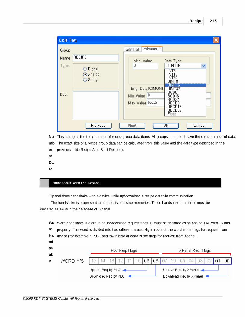
Recipe 215
© 2006 KDT SYSTEMS Co.Ltd. All Rights Reserved.
Nu
mb
er
of
Da
ta
This field gets the total number of recipe group data items. All groups in a model have the same number of data.
The exact size of a recipe group data can be calculated from this value and the data type described in the
previous field (Recipe Area Start Position).
Handshake with the Device
Xpanel does handshake with a device while up/download a recipe data via communication.
The handshake is progressed on the basis of device memories. These handshake memories must be
declared as TAGs in the database of Xpanel.
Wo
rd
Ha
nd
sh
ak
e
Word handshake is a group of up/download request flags. It must be declared as an analog TAG with 16 bits
property. This word is divided into two different areas. High nibble of the word is the flags for request from
device (for example a PLC), and low nibble of word is the flags for request from Xpanel.

CIMON-Xpanel216
© 2006 KDT SYSTEMS Co.Ltd. All Rights Reserved.
BIT
Ha
nd
sh
ak
e
The bit handshake must be declared as a digital TAG in database. It is set or reset by Xpanel.
This flag indicates that the recipe data transfer is under the progressing.
Therefore, by this flag, the device can recognize the fact that its recipe data are ready for use or not.
Gr
ou
p
Nu
mb
er
This field retains the group number for upload or download. And it is effective only when the recipe data
transfer is issued by device (PLC) side. The device can choose a group in Xpanel configuration file which is
wanted to be up/downloaded. The group number can be a number between 0 to 1023.
Following time chart shows the status of handshake signals during recipe data transfer. It is an example of
up/download issued by PLC side. For transfer a new recipe data from Xpanel to device (PLC), the group
number should be decided foremost and written to the memory of group number. And next, the device
signals the bit08 (or bit09) flag of word handshake. Immediately after detection of that signal, Xpanel sets the
bit handshake and starts to transfer the recipe group data which is designated by the group number field.
After the successful transfer, Xpanel resets the bit handshake signal and clears the word handshake also. The
device can recognize the completion of transfer through those handshake signals.
Following time chart shows an example of recipe data transfer issued by Xpanel side. All the handshake
signals are controlled by Xpanel. The group number field has no meaning at Xpanel issued transfer. Since the
group number was designated in the parameter of functions already (RcpUpload(), RcpDownload()) or does
not need the group number because data are not for file access (RcpMemUp(), RcpMemDown()). The device
can recognize the progress of recipe data transfer with word and bit handshake signals.

Recipe 217
© 2006 KDT SYSTEMS Co.Ltd. All Rights Reserved.
Post Process for Uploaded Data
Automatically
File Store On PLC
Managed Upload
This option is effective only for the uploaded data by device side. As explained in
previous section, the device (PLC) can control the uploading process by using
handshake signal (bit9 of word handshake) and a group number.
If this option is checked, Xpanel will store the received recipe group data to the
configuration file automatically at the end of upload process. At that moment, the
group number from device will be used to determine which group in a file should be
replaced with the newly received data. Stored group data will be retained permanently
in flash memory even while Xpanel is powered off. If this option is not checked, the
uploaded data will be stored only in RAM.
17.2 Recipe Operator Interface
Recipe Functions
Xpanel provides 9 functions for recipe operation.
Those functions can be used as command of touch operation as well as script. Following table shows a list
of recipe functions.
(Please refer to the ‘Script’ section for more information)
Function Description
RcpDownload(S1, R2) Read a group of recipe data from file, and download it to device
RcpUpload(S1, R2) Upload the specified recipe group data from device, and store it to file.
RcpStop(S1) Stop and terminate the processing job of specified recipe model.
RcpFileStore(S1, R2) Stores the recipe data to the file..

CIMON-Xpanel218
© 2006 KDT SYSTEMS Co.Ltd. All Rights Reserved.
RcpFileRead(S1, R2) Read the recipe data from file.
RcpMemDown(S1) Download the current recipe data to device.
RcpMemUp(S1) Upload the recipe data from device.
RcpCsvRd(S1, S2, R3) Read the recipe data from CSV formatted file.
RcpConfig() Pops up a dialog box for recipe data manipulation.
Recipe Dialog Box
RcpConfig() function pops up a dialog box on screen. This dialog box provides some tools for manipulating
recipe data in memory.
Each data item in a group can be modified by touch operation. Following picture shows a example of recipe
dialog box.
Save Save button stores the recipe group
data to the recipe configuration file.
The storage media can be the internal
flash memory of Xpanel or other
external none-volatile memory device
such as SD/MMC. It is dependent on
the location of project folder which is
determined on start-up.
Upload Upload button reads the recipe data
from device. Current recipe data in
memory will be discarded and
replaced with those of device. This
button gives the same result with the
function RcpMemUp()
Downl
oad
Download button writes current recipe
data in memory to device. This button
gives the same result with the
function RcpMemDown()
CSV File Importing
Xpanel provides a way to import the external recipe group data.

Recipe 219
© 2006 KDT SYSTEMS Co.Ltd. All Rights Reserved.
External data must be a CSV formatted file and the SD/MMC or USB memory can be used for importing
media.
Following picture shows the work flow of recipe data importing.
Writing a CSV file CSV formatted file can be generated by spreadsheet program of PC such as Excel.
A CSV file can include one group data and the first data of this file should be the number of
following recipe data. This number must same with the ‘Number of Data’ field of recipe
configuration dialog box.
Importing the
CSV file
on external
memory
RcpCsvRd() function is used for importing a CSV file from external memory media. External
memory can be the SD/MMC or USB memory. If there is no fault to access the CSV file in
external memory, the recipe group data will be loaded to RAM of Xpanel. After successful loading
of recipe group data, they can be manipulated in various ways. They can be stored in
configuration file and also can be downloaded to the device, Please refer to the ‘Script’ section
for more information about RcpCsvRd() function.

Top Level IntroThis page is printed before anew top-level chapter starts
Part
XVIII

System Memory 221
© 2006 KDT SYSTEMS Co.Ltd. All Rights Reserved.
18 System Memory
System Memory function supports useful continuous memory space for the script, recipe and so
on.
This function also uses continuous data storage at the script or editing buffer at the script.
· System Memory : Continuous Data Space
· Continuous data storage for the Script.
· Editing group data space for the Recipe
See :
· Using System Memory Tag
· Example of using system memory about opened page log.
· Editing recipe data using system memory
18.1 Using System Memory Tag
System Memory Configuration

CIMON-Xpanel222
© 2006 KDT SYSTEMS Co.Ltd. All Rights Reserved.
Select menu [Tools] -> [Project(P)]
“System Memory Size” configures system memory size. If it is inputted 1000 like above figure then it
assigns range 0 ~ 999.
Registering Tag
Register the tag at data base for use system memory as like virtual tag.
This case can handle system memory value directly and monitor the value.

System Memory 223
© 2006 KDT SYSTEMS Co.Ltd. All Rights Reserved.
Input tag name. Select the kind of tag.
(System Memory area must be used as the Digital/Analog tag.)
Select real tag at the general tab. Select “SYSTEM MEMORY” at the I/O device.
( “SYSTEM MEMORY” item has been registered basically.)
Input I/O address will be used. If it is inputted “5” like above figure then address 5 data can be handled ormonitored.
(If it is inputted less than 0 or out of the range assigned, the system tag will not be worked.)
18.2 Example of using system memory about opened page log.
Follow example shows the method of making opened page log by using system memory.
· Select system memory size
· Register two virtual tags at the data base.
Name : PAGE_NUM, Type : Analog, Initial Value : 0
Name : PAGE_LOG_SIZE, Type : Analog, Initial Value : 0

CIMON-Xpanel224
© 2006 KDT SYSTEMS Co.Ltd. All Rights Reserved.
· Register 10 system memory tags at the data base.
Name : SYSTEM_00, Type : Analog
Change I/O address as the follow figure and register 10 tags until SYSTEM_09.
· Select menu [Tools] -> [Script(S)]
· Create the script as follow.
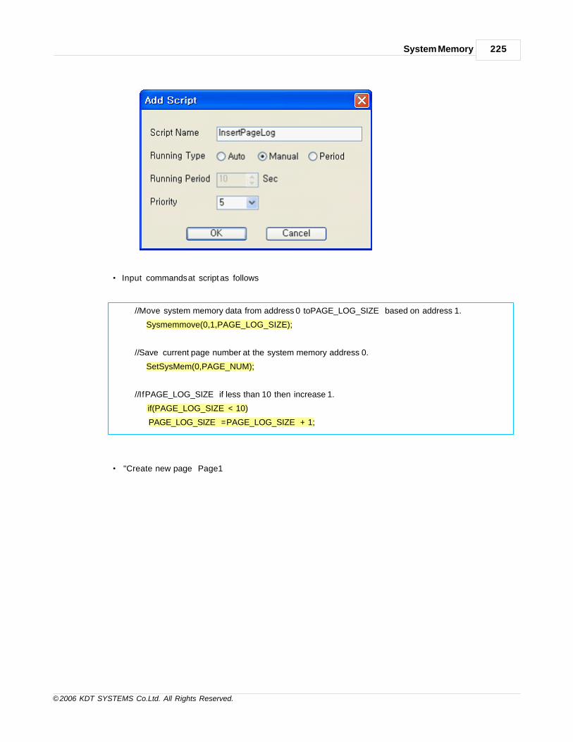
System Memory 225
© 2006 KDT SYSTEMS Co.Ltd. All Rights Reserved.
· Input commands at script as follows
// Move system memory data from address 0 to PAGE_LOG_SIZE based on address 1.
Sysmemmove(0,1,PAGE_LOG_SIZE);
// Save current page number at the system memory address 0.
SetSysMem(0,PAGE_NUM);
// If PAGE_LOG_SIZE if less than 10 then increase 1.
if(PAGE_LOG_SIZE < 10)
PAGE_LOG_SIZE = PAGE_LOG_SIZE + 1;
· "Create new page “Page1”

CIMON-Xpanel226
© 2006 KDT SYSTEMS Co.Ltd. All Rights Reserved.
· Select [Tools] -> [Page setup]
· Input as follow figure in the action tab.
· If “Page1” is opened, PAGE_NUM tag value is set 1 and runs InserPageLog function.
· Create “Page2”, “Page3” and input as above figure changing PAGE_NUM tag value.

System Memory 227
© 2006 KDT SYSTEMS Co.Ltd. All Rights Reserved.
· Arrange tag object at the page and let it indicates “SYSTEM_00” tag.
· Through the same method arrange SYSTEM_01, SYSTEM_02,…SYSTEM_09 tags at the page.
· Copy above objects and paste to all pages.
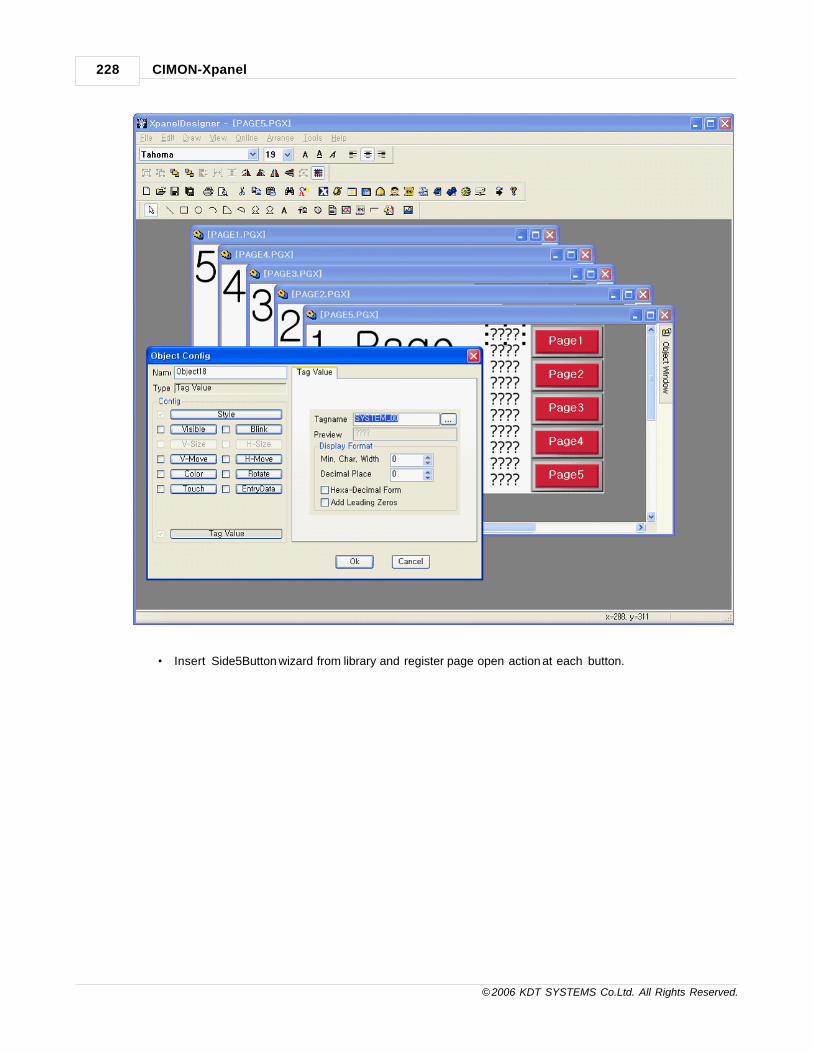
CIMON-Xpanel228
© 2006 KDT SYSTEMS Co.Ltd. All Rights Reserved.
· Insert Side5Button wizard from library and register page open action at each button.
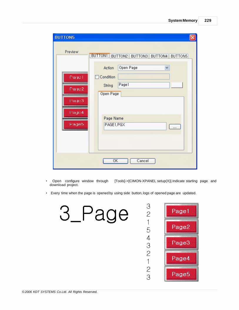
System Memory 229
© 2006 KDT SYSTEMS Co.Ltd. All Rights Reserved.
· Open configure window through [Tools]->[CIMON-XPANEL setup(X)].Indicate starting page anddownload project.
· Every time when the page is opened by using side button, logs of opened page are updated.

CIMON-Xpanel230
© 2006 KDT SYSTEMS Co.Ltd. All Rights Reserved.
< Xpanel acting page, recently opened page >
18.3 Editing recipe data using system memory
Bellow example shows the method of editing recipe internal buffer using system memory.
Registering System tag
Register system memory tag at the data base for displaying system value tag value at the monitor.
Register 10 tags address 0 ~ 9 according to the following figure.
Registering tag for Recipe model
Register tags for the Recipe model. Refer the manual for more details. In this example is registered
bellows.
Recipe Area Start Position : START
Handshake Word : CONTROL
Handshake Bit : CTL_BIT
Handshake Group Number : GROUP
Registering Recipe model

System Memory 231
© 2006 KDT SYSTEMS Co.Ltd. All Rights Reserved.
Register model for recipe working. Refer the manual for more details.
Page construction for editing system memory
Construct page for editing and displaying system memory. Arrange tag value object at the page and
register system memory tag.

CIMON-Xpanel232
© 2006 KDT SYSTEMS Co.Ltd. All Rights Reserved.
Check the EntryData and register same system memory tag.

System Memory 233
© 2006 KDT SYSTEMS Co.Ltd. All Rights Reserved.
Register remained 9 system memory tags at the page same method.
Make button to bring system memory from recipe data.

CIMON-Xpanel234
© 2006 KDT SYSTEMS Co.Ltd. All Rights Reserved.
Input commands as follows after selection of [Touch] -> [Command Expression] at the button
configuration.
When button is touched it brings buffer data of “SAMPLE” recipe model to system memory address 0. It
updates 10 areas from address 0 to 9.
RcpGetSysMem("SAMPLE",0)
Register button to transfer system memory to the recipe

System Memory 235
© 2006 KDT SYSTEMS Co.Ltd. All Rights Reserved.
Input commands as follows after selection of [Touch] -> [Command Expression] at the button
configuration.
When button is touched it transfers buffer data of “SAMPLE” recipe model to system memory address 0.
It updates 10 areas from address 0 to 9.
RcpSetSysMem("SAMPLE",0)
Making Recipe Upload Button
Input commands as follows after selection of [Touch] -> [Command Expression] at the button
configuration.
When button is touched it updates “SAMPLE” recipe model’s buffer by reading device’s data.
RcpMemUp("SAMPLE");
Making Recipe Download Button
Input commands as follows after selection of [Touch] -> [Command Expression] at the button
configuration.
When button is touched it downloads “SAMPLE” recipe model’s buffer data to device.
RcpMemDown("SAMPLE");

CIMON-Xpanel236
© 2006 KDT SYSTEMS Co.Ltd. All Rights Reserved.
· Save project and download project to Xpanel. It realizes download function about download at once after
reading continuous data and modifying
data according to order as like [Upload] -> [Bring recipe data to system memory] -> [Modifying system
memory] -> [Inputting system memory data] ->
[Download] in displaying monitor.

Top Level IntroThis page is printed before anew top-level chapter starts
Part
XIX

CIMON-Xpanel238
© 2006 KDT SYSTEMS Co.Ltd. All Rights Reserved.
19 Trend
Xpanel provides various kinds of trend functions. Each trend function has its own distinguishable and specialized
data manipulation method and trending style.
System engineer can choose the best fitting trend function among those trend functions for their application.
See :
· YT Trend / Scope Trend / SPC Trend / ST Trend / LOG Trend /
XY Trend
19.1 YT Trend
The ‘YT Trend’ is periodical time based generic trend. The data for trending are collected by Xpanel. Y axis
represents the value of trending data and X axis represents the time. Maximum 8 different data (pens) can be
shown in a trend window at the same time. Each pen has its own data buffer (RAM) with capacity of 5000 data.
The datum of each pen is sampled and stored periodically to this buffer by Xpanel. This buffer makes it possible
to support the historical trend of sampled data.
Trend Config
Display Basis Designate the side which displays the more recent data. For example, if the ‘Right’ is
selected, the trend screen will be

Trend 239
© 2006 KDT SYSTEMS Co.Ltd. All Rights Reserved.
scrolled right to left direction and the right most data will be the most recent data.
Display Time Designate the time span of trend window. The maximum configurable time can be
derived from the sampling time.
(Max. 5000 x Sampling time)
Sampling
Time
Designate the data sampling time. Xpanel will collect the pen data at every this sampling
time.
The data buffer of a pen has the capacity of 5000 samples.
File Saving This option can be used when the historical trend data must be preserved in non-volatile
memory. Without this option, the historical data are stored in RAM (volatile memory).
One of three kinds of non-volatile memory media can be chosen for the storage of
historical data. Following table shows the logging path of each media. The log file has its
own format, it cannot be read other application software.
Media Logging Path
Main Memory //Xpanel/Log/<trend name>/
SD Memory //Log/<trend name>/
USB Memory //Log/<trend name>/
Object Style & Trend Area Style
The ‘Object Style’ and ‘Trend Area Style’ configuration tab decide the color of trend window as shown in the
following sample picture.

CIMON-Xpanel240
© 2006 KDT SYSTEMS Co.Ltd. All Rights Reserved.
Pen
A trend can be assigned maximum 8 pens. Each pen has its own properties and these properties must be
configured individually.

Trend 241
© 2006 KDT SYSTEMS Co.Ltd. All Rights Reserved.
Tagname Define a TAG for each pen. Xpanel will log the value of this TAG in memory
periodically. Maximum 5000 data can be logged in memory for each pen.
Comment Designate a display name of pen. This name will be shown at the bottom of trend
window, as shown in the following example.
Min Value / Max
Value
Designate the minimum and maximum values of Y axis. If these values are denoted as
question mark (‘?’), those values defined in the TAG database will be applied.
Pen Color Designate a color to the pen.

CIMON-Xpanel242
© 2006 KDT SYSTEMS Co.Ltd. All Rights Reserved.
Control Button
If the ‘Show Control Buttons’ option is checked, the operator can use the ‘Control Button’ of the trend as
shown in the following example.
Switch the trending mode between real-time and historical.
Up and down page of the trending window. These buttons are activated only at
historical mode.
Zoom in or out page of the trending window.
Change the primary pen. Min/Max values of Y axis are those of the primary pen.
Open the online trend configuration tool. The following picture shows the online
configuration tool window. Operator can change the monitoring time and pen by using
this tool.

Trend 243
© 2006 KDT SYSTEMS Co.Ltd. All Rights Reserved.
Legend
The date and TAG value can be shown or hidden by option in ‘Legend’ tab.
Following example window shows the ‘Date’ and ‘TAG Value’ area which can be controlled by above options.
Grid
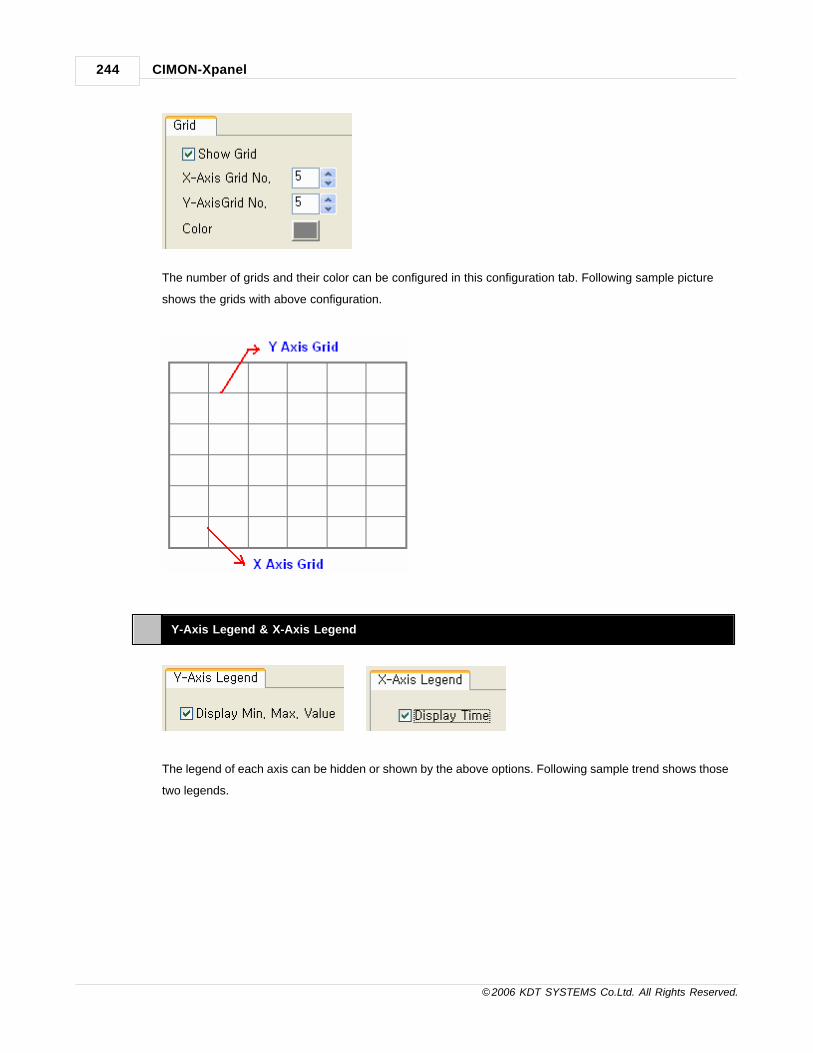
CIMON-Xpanel244
© 2006 KDT SYSTEMS Co.Ltd. All Rights Reserved.
The number of grids and their color can be configured in this configuration tab. Following sample picture
shows the grids with above configuration.
Y-Axis Legend & X-Axis Legend
The legend of each axis can be hidden or shown by the above options. Following sample trend shows those
two legends.

Trend 245
© 2006 KDT SYSTEMS Co.Ltd. All Rights Reserved.
19.2 Scope Trend
The ‘Scope Trend’ is useful at the system of test equipment. This trend can display maximum 8 different sampled
data lists on the same window.
The sampled data lists can be located in device memory or Xpanel’s log file.
Trend Config
Display Basis Designate the side which represents the origin of X axis. For example, if the ‘Right’ is
selected, the right most trend screen will be the position of index zero (0) data.

CIMON-Xpanel246
© 2006 KDT SYSTEMS Co.Ltd. All Rights Reserved.
Object Style & Line Color
The ‘Object Style’ and ‘Line Color’ configuration tab decide the color of trend window as shown in the
following sample picture.
Pen
A trend can be assigned maximum 8 pens. Each pen has its own properties and these properties must be
configured individually.
The scope trend can read the pen data not only from the device memory but also from the logged data file
of Xpanel.

Trend 247
© 2006 KDT SYSTEMS Co.Ltd. All Rights Reserved.
Using DataLog
Model
If this field was checked, then all the declared data logger models are listed in the
combo-box as shown in the following picture.
When one of data logger models is chosen, the TAGs registered in this data logger
model are automatically listed in the pen list.
If this field was not checked, then Xpanel will read pen data from the device
memory. Following dialog box is used for defining the properties of each pen.
Tagname Define a TAG for each pen. In case of scope trend, this TAG’s address represents the
origin of a Y axis data list.
Comment Designate a display name of pen.
Min Value / Max
Value
These items have no meaning in scope trend.
Pen Color Designate a color to the pen.

CIMON-Xpanel248
© 2006 KDT SYSTEMS Co.Ltd. All Rights Reserved.
Grid
The number of grids and their color can be configured in this configuration tab. Following sample picture
shows the grids with above configuration.
Y-Axis Legend & X-Axis Legend
The legend of each axis can be hidden or shown by the above options. Following sample trend shows those
two legends. The ‘Size (Pixcels)’ configuration item decides the width of Y-Axis legend.

Trend 249
© 2006 KDT SYSTEMS Co.Ltd. All Rights Reserved.
Scope Option
Data Porint Every data in trend window can be distinguished by dot. These dots have the shape of
rectangular.
· [Size (Pixels)] : Designate the size of dot in the unit of pixel.
Draw Border The outline of the trend window can be shown by this option. Please refer to the
following sample picture.

CIMON-Xpanel250
© 2006 KDT SYSTEMS Co.Ltd. All Rights Reserved.
Scope Tags
Following TAGs must be configured in this configuration tab.
Control Bit This field is effective only on device memory based trend. If the trend is based on data
logger model, just leave this field as empty.
If the trend is based on the device memory sampled data, designate a real digital TAG to
this field. (The virtual digital TAG can not be used for this ‘Control Bit’.) The TAG is used for
handshaking purpose while transferring sampled data. The PLC sequence program can be

Trend 251
© 2006 KDT SYSTEMS Co.Ltd. All Rights Reserved.
noticed the data transfer by monitoring ON (1) signal of this TAG. During this signal, the
time schedule data should not be modified for data consistency.
Control Designate an analog TAG. The value of this TAG controls the trend window as shown in the
following table.
Value Action
2 Clear the trending window
3 Clear the current trend window and draw a new time schedule trend.
Other Values No action.
This analog TAG can be a real TAG as well as a virtual TAG. This means that the sequence
program in PLC can control or update the trend window of Xpanel.
Data Count This field indicates total number of sampled data in device memory. It can be the range
between 1 and 2048. This field is not effective on data logger model based trend.
Minimum /
Maximum
These fields specify the range of Y axis. The specified range is effective to all pens.
Block Number This field is effective only on the data logger based trend. The block number of logged data
is identified by the value of this TAG.
19.3 SPC Trend
The ‘SPC Trend’ has no time axis. All axes are based on sampled or predefined value lists stored in the device.
The SPC trend visualizes the relationship between those data. X axis can be assigned only one data list. Y axis can
be assigned maximum 8 different data lists. Note that all those data lists must be stored in device memory.
Xpanel supports a real-time cursor which represents the position from current X and Y values.
Following picture shows the first configuration tab page of SPC trend. As shown in this picture, there is no need
to time configuration.
Trend Config

CIMON-Xpanel252
© 2006 KDT SYSTEMS Co.Ltd. All Rights Reserved.
Display Basis Designate the side which represents the minimum value of X axis. For example, if the
‘Right’ is selected, the right most trend screen will be the position of lowest X axis value.
Object Style & Line Color
The ‘Object Style’ and ‘Line Color’ configuration tab decide the color of trend window as shown in the
following sample picture.

Trend 253
© 2006 KDT SYSTEMS Co.Ltd. All Rights Reserved.
Pen
A trend can be assigned maximum 8 pens. Each pen has its own properties and these properties must be
configured individually.
Tagname Define a TAG for each pen. In case of SPC trend, this TAG’s address represents the
origin of a Y axis data list.
Comment Designate a display name of pen.

CIMON-Xpanel254
© 2006 KDT SYSTEMS Co.Ltd. All Rights Reserved.
Min Value / Max
Value
These items have no meaning in SPC trend.
Pen Color Designate a color to the pen.
Grid
The number of grids and their color can be configured in this configuration tab. Following sample picture
shows the grids with above configuration.
Y-Axis Legend & X-Axis Legend
The legend of each axis can be hidden or shown by the above options. Following sample trend shows those
two legends. The ‘Size (Pixcels)’ configuration item decides the width of Y-Axis legend.
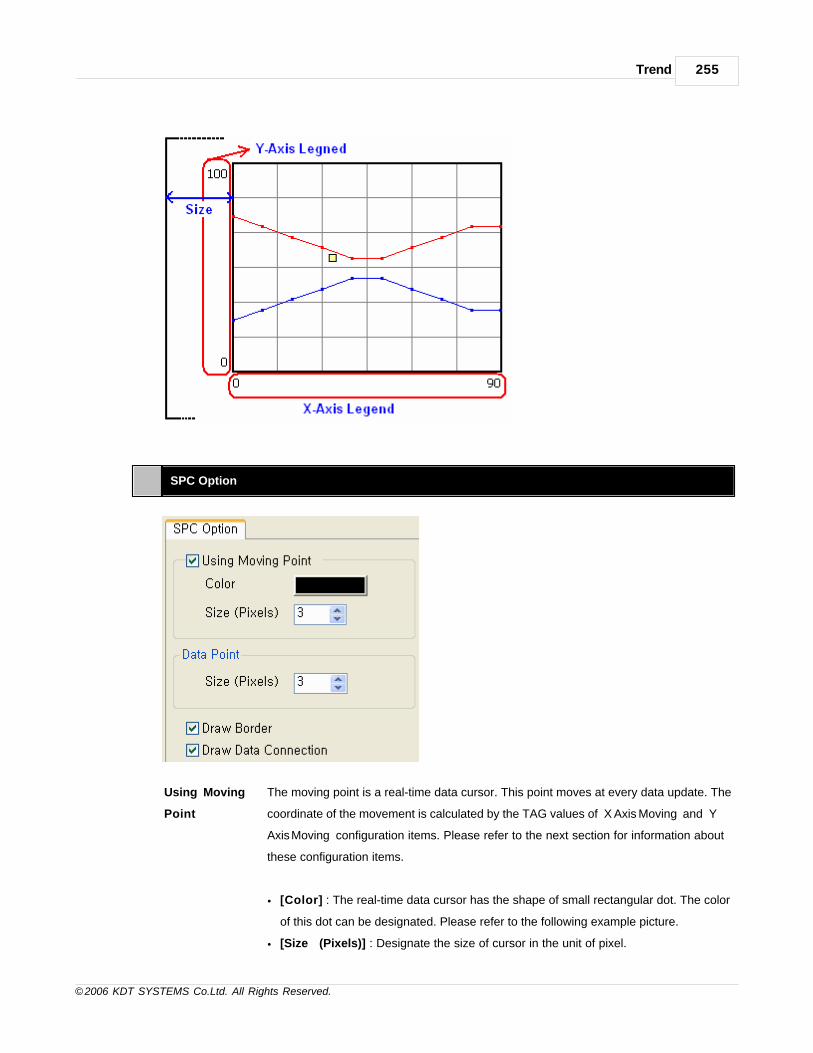
Trend 255
© 2006 KDT SYSTEMS Co.Ltd. All Rights Reserved.
SPC Option
Using Moving
Point
The moving point is a real-time data cursor. This point moves at every data update. The
coordinate of the movement is calculated by the TAG values of ‘X Axis Moving’ and ‘Y
Axis Moving’ configuration items. Please refer to the next section for information about
these configuration items.
· [Color] : The real-time data cursor has the shape of small rectangular dot. The color
of this dot can be designated. Please refer to the following example picture.
· [Size (Pixels)] : Designate the size of cursor in the unit of pixel.

CIMON-Xpanel256
© 2006 KDT SYSTEMS Co.Ltd. All Rights Reserved.
Data Point Every data in trend window can be distinguished by dot. These dots have the shape of
rectangular.
· [Size (Pixels)] : Designate the size of dot in the unit of pixel.
Draw Border The outline of the trend window can be shown by this option. Please refer to the
following sample picture.
Draw Data
Connection
If this option is checked, lines will be drawn between every neighboring data. Please
refer to the following sample picture.
SPC Tags

Trend 257
© 2006 KDT SYSTEMS Co.Ltd. All Rights Reserved.
Following TAGs must be configured in this configuration tab.
Control Designate an analog TAG. The value of this TAG controls the trend window as shown in
the following table.
Value Action
1 Draw a new trend without clearing (overwrite).
2 Clear the trending window
3 Clear the current trend window and draw a new trend.
Other Values No action.
This analog TAG can be a real TAG as well as a virtual TAG. This means that the
sequence program in PLC can control or update the trend window of Xpanel.
Data Count Designate an analog TAG. The value of this TAG represents the number of data be
drawn in the trend window. It can be a value between 0 and 2048.
X Axis Min. /
Max
Designate analog TAGs. The values of these TAGs reconfigure the range of X axis when
the ‘Control’ TAG’s value is changed to 1 or 3.
Y Axis Min. /
Max
Designate analog TAGs. The values of these TAGs reconfigure the range of Y axis when
the ‘Control’ TAG’s value is changed to 1 or 3.
Control Bit Designate a real digital TAG. (The virtual digital TAG can not be used for this ‘Control
Bit’.) The TAG is used for handshaking purpose while the transfer of trend data. The
PLC sequence program can be noticed the data transfer by monitoring ON (1) signal of
this TAG. During this signal, the trend data should not be modified for data consistency.
X Axis Moving /
Y Axis Moving
Designate analog TAGs which represent the coordinate of real-time cursor. These
configurations are valid only when the ‘Using Moving Point’ option of ‘SPC Option’ tab
was checked.
X Axis Start Designate a real analog TAG. (The virtual TAG can not be used in this field.) The device
address of the designated TAG is considered as the origin (start address) of X axis data.
Xpanel assumes that the data are stored continuously in device memory and the length
of data is the value stored in the TAG of ‘Data Count’ field.

CIMON-Xpanel258
© 2006 KDT SYSTEMS Co.Ltd. All Rights Reserved.
19.4 ST Trend
The ‘ST Trend’ is useful at the system of temperature control and monitoring. This trend provides a display
solution for time schedule of control. Maximum 8 different schedules and 2 real-time traces can be displayed in
the same trend window. The schedule data are composed of a time span and destination value pair. Each
schedule data can include up to 2048 pairs of schedule point. The X axis of ST trend is an accumulated time of
those schedule data. The configuration of ST trend is described as followings.
Trend Config
Display Basis Designate the side which represents the time origin of X axis. For example, if the ‘Right’
is selected, the right most trend screen will be the position of zero (0).
Sampling Time Designate the sampling time for real-time trace. The unit of this time is 100 mSec.
Object Style & Line Color

Trend 259
© 2006 KDT SYSTEMS Co.Ltd. All Rights Reserved.
The ‘Object Style’ and ‘Line Color’ configuration tab decide the color of trend window as shown in the
following sample picture.
Pen
A pen of ST trend represents a time schedule. Maximum 8 different time schedules can be displayed in the
same trend window.
The pen of ST trend must have a given data format. Each point in a time schedule is represented by a pair
of data as shown in the above diagram. One preceding datum (delta-T of above diagram) represents the
time duration and the other following datum (v of above diagram) represents the control value. These two
data pair represents a point in trend window and those pairs should be stored in the continuous device
memory.
The TAGs which will be designated in the following dialog box should have the address of the first delta-T.

CIMON-Xpanel260
© 2006 KDT SYSTEMS Co.Ltd. All Rights Reserved.
Tagname Designate a TAG which represents the first data memory address of time schedule list.
Comment Designate a description of the pen.
Min Value / Max
Value
These items have no meaning in ST trend.
Pen Color Designate a color to the pen.
Data Count Tags
Designate the analog TAG which has the number of total pen data. As noted in the previous part, a pen data
is expressed with a pair of two values. Hence, this TAG must have the value of 2n (n is the number of time

Trend 261
© 2006 KDT SYSTEMS Co.Ltd. All Rights Reserved.
schedule points).
Grid
The number of grids and their color can be configured in this configuration tab. Following sample picture
shows the grids with above configuration.
Y- Axis Legend & X-Axis Legend
The legend of each axis can be hidden or shown by the above options. Following sample trend shows those
two legends. The ‘Size (Pixcels)’ configuration item decides the width of Y-Axis legend.

CIMON-Xpanel262
© 2006 KDT SYSTEMS Co.Ltd. All Rights Reserved.
The X-Axis legend has 4 different time expression formats as shown in the above picture. One of them can
be chosen as an actual format.
ST Trend Options
Trace Point Every trace data can be distinguished by dots. These dots have the shape of
rectangular.
· [Color] : The real-time trace data cursor has the shape of small rectangular dot. The

Trend 263
© 2006 KDT SYSTEMS Co.Ltd. All Rights Reserved.
color of this dot can be designated. Please refer to the following example picture.
· [Size (Pixels)] : Designate the size of dot in the unit of pixel.
Data Point Every time schedule data in trend window can be distinguished by dot. These dots have
the shape of rectangular.
[Size] : Designate the size of dot in the unit of pixel.
Draw Border The outline of the trend window can be shown by this option. Please refer to the
following sample picture.
ST Tags
Following TAGs must be configured in this configuration tab.

CIMON-Xpanel264
© 2006 KDT SYSTEMS Co.Ltd. All Rights Reserved.
Control Bit Designate a real digital TAG. (The virtual digital TAG can not be used for this ‘Control Bit’.)
The TAG is used for handshaking purpose while the transfer of time schedule data. The PLC
sequence program can be noticed the data transfer by monitoring ON (1) signal of this TAG.
During this signal, the time schedule data should not be modified for data consistency.
Control Designate an analog TAG. The value of this TAG controls the trend window as shown in the
following table.
Value Action
2 Clear the trending window
3 Clear the current trend window and draw a new time schedule trend.
4 Starts the real time trace
5 Pauses the real time trace
6 Resets the real time trace
Other Values No action.
This analog TAG can be a real TAG as well as a virtual TAG. This means that the sequence
program in PLC can control or update the trend window of Xpanel.
Trace Point Designate an analog TAG to be traced. ST trend collects the data of this TAG at every
sampling period, and stores the data in memory up to 2048 samples. Those sampled trace
data will be drawn on the trending window by real time. The real time trace data can be
easily visualized and compared with the time schedule data which were drawn already in
trending window.

Trend 265
© 2006 KDT SYSTEMS Co.Ltd. All Rights Reserved.
Minimum
Value / Using
Fixed Minimum
Value
‘Minimum’ represents the minimum value of the Y axis. It can be designated by not only a
fixed value but also a TAG. If the ‘Using Fixed Minimum Value’ item was checked, the
minimum value should be given by fixed constant.
Maximum
Value / Using
Fixed Maximum
Value
‘Maximum’ represents the maximum value of the Y axis. It can be designated by not only a
fixed value but also a TAG. If the ‘Using Fixed Maximum Value’ item was checked, the
maximum value should be given by fixed constant.
Trace Display
Time / Using
Fixed Trace
Display Time
‘Trace Display Time’ represents the maximum value of the X axis. It can be designated by not
only a fixed value but also a TAG. The unit of display time is second. If the ‘Using Fixed Trace
Display Time’ item was checked, the maximum time value in second should be given by fixed
constant.
19.5 LOG Trend
The ‘Log Trend’ is similar to the ‘YT Trend’. It is based on a time axis, and 16 different data can be displayed at
the same time.
However, the ‘Log Trend’ does not require the periodical data sampling. The data can be sampled or initialized at
any time by a trigger.
Trend Config
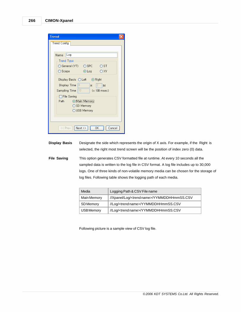
CIMON-Xpanel266
© 2006 KDT SYSTEMS Co.Ltd. All Rights Reserved.
Display Basis Designate the side which represents the origin of X axis. For example, if the ‘Right’ is
selected, the right most trend screen will be the position of index zero (0) data.
File Saving This option generates CSV formatted file at runtime. At every 10 seconds all the
sampled data is written to the log file in CSV format. A log file includes up to 30,000
logs. One of three kinds of non-volatile memory media can be chosen for the storage of
log files. Following table shows the logging path of each media.
Media Logging Path & CSV File name
Main Memory //Xpanel/Log/<trend name>/YYMMDDHHmmSS.CSV
SD Memory //Log/<trend name>/YYMMDDHHmmSS.CSV
USB Memory //Log/<trend name>/YYMMDDHHmmSS.CSV
Following picture is a sample view of CSV log file.

Trend 267
© 2006 KDT SYSTEMS Co.Ltd. All Rights Reserved.
Object Style & Line Color
The ‘Object Style’ and ‘Line Color’ configuration tab decide the color of trend window as shown in the
following sample picture.
Pen

CIMON-Xpanel268
© 2006 KDT SYSTEMS Co.Ltd. All Rights Reserved.
A trend can be assigned maximum 16 pens. Each pen has its own properties and these properties must be
configured individually.
Tagname Define a TAG for each pen.
Comment Designate a display name of the pen.
Min Value / Max
Value
In log trend each pen can be assigned different minimum and maximum Y axes values.
The minimum value must be assigned as a smaller value than maximum value.
Pen Color Designate a color to the pen.
Grid
The number of grids and their color can be configured in this configuration tab. Following sample picture
shows the grids with above configuration.
If ‘Using Multi-Channel’ of ‘Log Option’ tab was checked, the Y-Axis grid number has no meaning. Y-axis grid

Trend 269
© 2006 KDT SYSTEMS Co.Ltd. All Rights Reserved.
is not displayed when multi-channel trend mode.
Y-Axis Legend & X-Axis Legend
The legend of each axis can be hidden or shown by the above options. Following sample trend shows those
two legends. The ‘Size (Pixcels)’ configuration item decides the width of Y-Axis legend.

CIMON-Xpanel270
© 2006 KDT SYSTEMS Co.Ltd. All Rights Reserved.
Log Option
The log trend specific options can be configured in this tab.
Buffer Size Log trend keeps the sampled data in Xpanel’s memory. This field specifies the size of
buffer for sampled data.
Sampling Type Log trend can handle not only periodically sampled data but also trigger sampled data.
This field decides which type of sampling to be used.

Trend 271
© 2006 KDT SYSTEMS Co.Ltd. All Rights Reserved.
Sampling Time If the periodical sampling type was chosen at ‘Sampling Type’ field, the trend needs the
period in 100mSec. unit.
Trigger Tag If the trigger sampling type was chosen at ‘Sampling Type’ field, the trend needs the
name of TAG which represents the trigger signal. The sampling is done when this signal
changes from zero to non-zero value.
Control Tag This TAG controls the operation of trend window. The table below shows the effects of
each code that this control TAG can have.
Value Action
0 Do the normal sampling and trending job.
1 Pause the sampling and trending job.
2 Reset and clear the sampling buffer.
Other Values No action.
Data Point : Size
(Pixels)
Every sampled data in trend window can be distinguished by dot. These dots have the
shape of rectangular. Designate the size of dot in the unit of pixel.
Draw Border The outline of the trend window can be shown by this option. Following picture shows
the border of trend window.
19.6 XY Trend
The ‘XY Trend’ has no time axis like the ‘SPC Trend’. And it does not take block data from device, but the Xpanel
collects the trending data periodically or on every trigger event. This trend can display the correlation between a
designated data (X-axis) and up to 16 data (Y-axis). Maximum 800 pairs of correlation data are maintained in
memory.

CIMON-Xpanel272
© 2006 KDT SYSTEMS Co.Ltd. All Rights Reserved.
Trend Config
File Saving
This option generates CSV formatted file at runtime. At every 10 seconds all the sampled data is written to
the log file in CSV format. A log file includes up to 30,000 logs. One of three kinds of non-volatile memory
media can be chosen for the storage of log files. Following table shows the logging path of each media.
Media Logging Path & CSV File name
Main Memory //XPanel/Log/<trend name>/YYMMDDHHmmSS.CSV
SD Memory //Log/<trend name>/YYMMDDHHmmSS.CSV
USB Memory //Log/<trend name>/YYMMDDHHmmSS.CSV
Following picture is a sample view of CSV log file.

Trend 273
© 2006 KDT SYSTEMS Co.Ltd. All Rights Reserved.
Object Style & Line Color
The ‘Object Style’ and ‘Line Color’ configuration tab decide the color of trend window as shown in the
following sample picture.
Pen

CIMON-Xpanel274
© 2006 KDT SYSTEMS Co.Ltd. All Rights Reserved.
A trend can be assigned maximum 16 pens. Each pen has its own properties and these properties must be
configured individually.
Tagname Define a TAG for each pen.
Comment Designate a display name of the pen.
Min Value / Max
Value
In log trend each pen can be assigned different minimum and maximum Y axes values.
The minimum value must be assigned as a smaller value than maximum value.
Pen Color Designate a color to the pen.
Grid
The number of grids and their color can be configured in this configuration tab. Following sample picture

Trend 275
© 2006 KDT SYSTEMS Co.Ltd. All Rights Reserved.
shows the grids with above configuration.
Y-Axis Legend & X-Axis Legend
The legend of each axis can be hidden or shown by the above options. Following sample trend shows those
two legends. The ‘Size (Pixcels)’ configuration item decides the width of Y-Axis legend.
XY Option
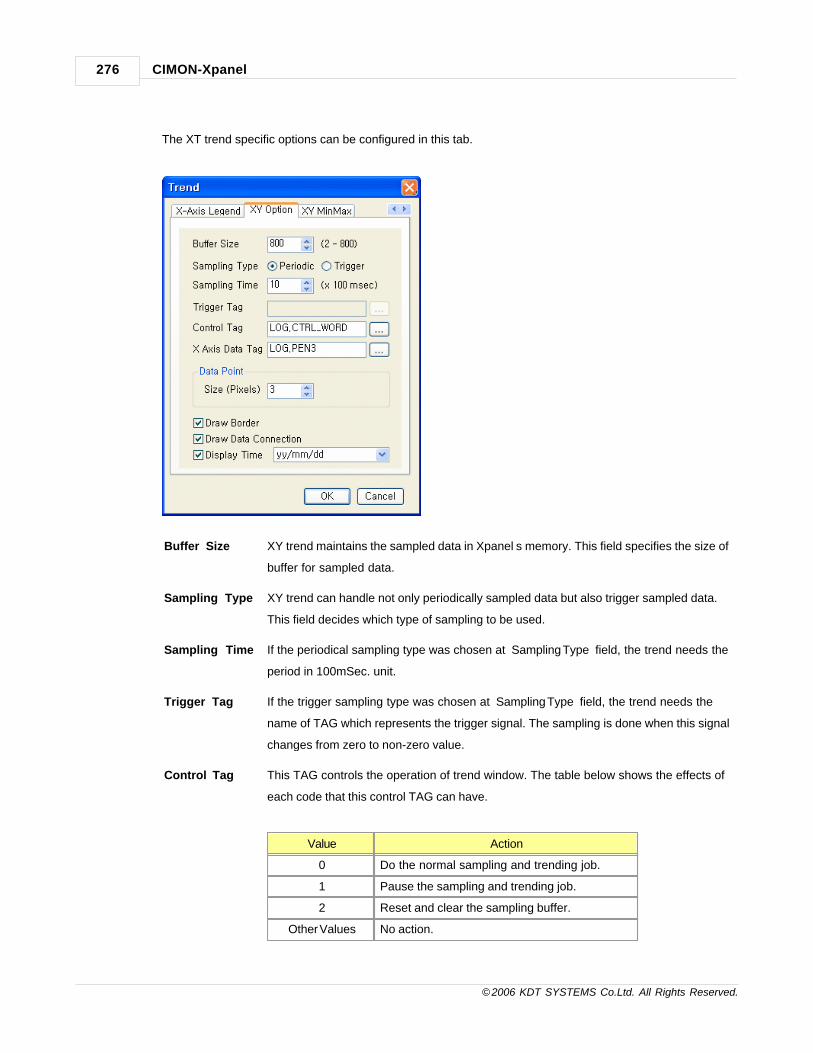
CIMON-Xpanel276
© 2006 KDT SYSTEMS Co.Ltd. All Rights Reserved.
The XT trend specific options can be configured in this tab.
Buffer Size XY trend maintains the sampled data in Xpanel’s memory. This field specifies the size of
buffer for sampled data.
Sampling Type XY trend can handle not only periodically sampled data but also trigger sampled data.
This field decides which type of sampling to be used.
Sampling Time If the periodical sampling type was chosen at ‘Sampling Type’ field, the trend needs the
period in 100mSec. unit.
Trigger Tag If the trigger sampling type was chosen at ‘Sampling Type’ field, the trend needs the
name of TAG which represents the trigger signal. The sampling is done when this signal
changes from zero to non-zero value.
Control Tag This TAG controls the operation of trend window. The table below shows the effects of
each code that this control TAG can have.
Value Action
0 Do the normal sampling and trending job.
1 Pause the sampling and trending job.
2 Reset and clear the sampling buffer.
Other Values No action.

Trend 277
© 2006 KDT SYSTEMS Co.Ltd. All Rights Reserved.
Data Point : Size
(Pixels)
Every sampled data in trend window can be distinguished by dot. These dots have the
shape of rectangular. Designate the size of dot in the unit of pixel.
Draw Border The outline of the trend window can be shown by this option. Following picture shows
the border of trend window.
Draw Data
Connection
This option makes Xpanel draw the line between data points. If this option was not
checked, then following trend would be displayed. There is no line between points.
Display Time Xpanel can display the time of last sampled data. This option controls the time will be
shown or not. Please see the picture of ‘Draw Border’ option above.
XY Min/Max
The minimum and maximum values of x axis are configured in this tab. These configurations can be not only
static numbers (fixed value) but also TAGs. When a TAG is assigned to the minimum or maximum value, the
range of x axis would be changed dynamically at runtime.

CIMON-Xpanel278
© 2006 KDT SYSTEMS Co.Ltd. All Rights Reserved.

Top Level IntroThis page is printed before anew top-level chapter starts
Part
XX

CIMON-Xpanel280
© 2006 KDT SYSTEMS Co.Ltd. All Rights Reserved.
20 String Editor
String editor constructs a number of string groups. These string groups are managed like string tables at
runtime.
Each group can be distinguished by group number. And all the strings defined in each group can be referenced by
index number.
Constructed string groups are useful when there is a need to make (or display) different string according to the
status code.
It can be accomplished by two different ways as shown in the following picture.
One method is done by the String Value graphic object and the other is done by the StringTable() script
function.
These two different applications will be described in next sections of this manual.
See :
· String Construction
20.1 String Construction
String Group Construction
Click - the ‘Tools’-‘String Editor’ menu or the icon.

String Editor 281
© 2006 KDT SYSTEMS Co.Ltd. All Rights Reserved.
Add String
Group
A new string group will be created by this icon (menu).
Delete String
Group
This icon (menu) deletes a group.
Add String A new string can be added to the current group by this icon (menu).
Edit StringA string can be modified by this icon or double click of mouse.
Delete String This icon deletes a selected string.
Insert Multiple Language StringGroup
A new multiple language string group will be created by this icon(menu).Please refer to the section of "Using Multiple Language".

CIMON-Xpanel282
© 2006 KDT SYSTEMS Co.Ltd. All Rights Reserved.
String Display
Ho
w
to
us
e ‘
Str
ing
Val
ue'
Click - the 'Draw’-‘String Value' menu

String Editor 283
© 2006 KDT SYSTEMS Co.Ltd. All Rights Reserved.
* The string is not output when there is no input string of the value of analog tag in the input string table. (Null)
Ho
w
to
us
e ‘
Stri
ng
Ta
ble
()'
1) Register - String Tag
(It is necessary to register the string tag that displays the script to use the script.)

CIMON-Xpanel284
© 2006 KDT SYSTEMS Co.Ltd. All Rights Reserved.
2) Click - [Tools] -> [Scripts] -> [Add Script]
3) Write - Script Program
Following script example shows the usage of ‘StringTable()’ function. For more information about the
‘StringTable()’, please refer to the section of ‘Script’.
4) Select a Object and Click - [Draw] -> [Tag] -> [Tag Name]
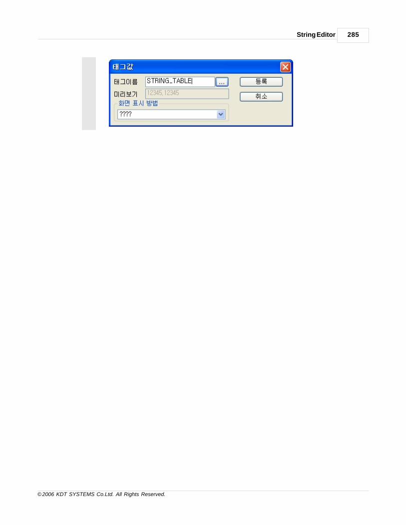
String Editor 285
© 2006 KDT SYSTEMS Co.Ltd. All Rights Reserved.

Top Level IntroThis page is printed before anew top-level chapter starts
Part
XXI

Using Multiple Language 287
© 2006 KDT SYSTEMS Co.Ltd. All Rights Reserved.
21 Using Multiple Language
· You can change the displaying language to Korean, Japanese or Chinese by using multiple
language tables.
· If your windows system based language is English, you must install MUI for multiple language.
You can download MUI at the Microsoft home page (www.micorsoft.com).
See :
· How to Set Multiple Language
· Multiple language string display
· Using Multiple Language (Change the displayed language by using multiple language table)
21.1 Multiple Language setup
This manual provides how to use Multiple Language.
By the function, languages of various countries are displayed to the screen.
IN THIS TOPIC :
Register IME Language and IME Selection
Register IME
In English Window, IME should be used for inputting the language of another country(Japan, China..).
Following pictures describes how to register IME.
1. Click - [Control Panel] -> [Regional and Language Options]
2. Select - "Languages" Tab -> Click - [Details...]

CIMON-Xpanel288
© 2006 KDT SYSTEMS Co.Ltd. All Rights Reserved.
3. Check - language and the IME registered in the English Window.
4. For example, if you want to input Japanese, Japanese and one more IME should be registered in the
installed service.
5. How to register IME
5.1. Click - [Add]
5.2 Select - Language in 'Input Language'

Using Multiple Language 289
© 2006 KDT SYSTEMS Co.Ltd. All Rights Reserved.
6. Select - IME in 'Keyboard layout/IME'. When the input language is selected, the basic IME is
automatically selected.
7. Click - [Ok]
Language and IME Selection
1. Click - [Control Panel] -> [Regional and Language Options]
2. Select - "Languages" Tab -> Click - [Details...]
3. Click - [Language Bar], Check - "Show the Language Bar on the desktop", Click - [Ok]
4. Select - Language of "Language Bar"

CIMON-Xpanel290
© 2006 KDT SYSTEMS Co.Ltd. All Rights Reserved.
5. Select - IME by clicking IME icon.
6. Letters are input via the selected IME.
21.2 Multiple language string display
Make - Page to input the string. Register - String by using each language.
Register Japanese String
1. Change the language to the Japanese in the "Language Bar".
2. Select - [Microsoft Natural Input 2002 ver.8.1] by clicking IME icon ( To select the relative item, the IME of the relative language should be registered in the window. Refer to the "Multiple Language setup")
3. Change - Input Mode(Hiragana) by clicking "Input Mode" button
4. Input - Japanese using Keyboard

Using Multiple Language 291
© 2006 KDT SYSTEMS Co.Ltd. All Rights Reserved.
5. Change the font to the "MS Gothic" in Font Toolbar. MS Gothic selected here is a Japanese basic
font.
It is possible that if the inputted string is not expressed as a designated font, it might not be
expressed normally, so change to the font of the relative country.
Register Chinese String
1. Change the language to the Chinese in the "Language Bar".
2. Select - [Microsoft Pinyin IME 3.0] by clicking IME icon
3. Change - Input Mode(Chinese) by clicking "Input Mode" button
4. Input - Chinese using Keyboard
5. Change the font to the "SimSun" in Font Toolbar. SimSun selected here is a Chinese basic font.

CIMON-Xpanel292
© 2006 KDT SYSTEMS Co.Ltd. All Rights Reserved.
It is possible to use it by inputting other languages except Japanese and Chinese to Xpanel.
21.3 Using Multiple Language (Change the displayed language byusing multiple language table)
· You can change the displaying language to Korean, Japanese or Chinese by using multiple
language tables.
· If your windows system based language is English, you must install MUI for multiple language.
You can download MUI at the Microsoft home page (www.micorsoft.com).
IN THIS TOPIC :
Configure Multiple Language
Register Multiple Language Table
Multiple language table display by using multiple language string.
Configure Multiple Language
1. Tools -> Project
2. Click Language Configuration button to open multi language configuration window.

Using Multiple Language 293
© 2006 KDT SYSTEMS Co.Ltd. All Rights Reserved.
3. Check “use multiple language” for using multiple language.
4. Register analog tag at “Table Control Tag” to control column. For example, above figure
shows that selects valid tag as like “COLSEL” and
it decides referencing column by its value.
5. When program runs the initial column indicated by ‘Table initial Value’.
6. Register language name and representative font at Language 0 ~ 9.
Language string register at ‘multiple language tables’ and it displayed here with registered
name and font.
Register Multiple Language Table
1. To input language string at multiple language tables, select Tools-> String Editor.

CIMON-Xpanel294
© 2006 KDT SYSTEMS Co.Ltd. All Rights Reserved.
2. Before you register multiple language tables, click button () to register language which
will be used.
3. After above language setting, Column 0 is Korean(Gulim), Column 1 is Chineses(SimSun)
and Column 2 is Japanese(MS Gothic).
4. After complete registering language, click ‘OK’ to save the configurations.

Using Multiple Language 295
© 2006 KDT SYSTEMS Co.Ltd. All Rights Reserved.
5. Click “Add String Group” button (), select “Multiple Column” and then “OK”. Multiple
column is string group having 16 columns and
Single column is string group having only one column.
6. Select one group in the already registered, click “Add String” button() to open add string
window.
7. Input string at each column while changing IME. At above example shows inputting multiple
languages.

CIMON-Xpanel296
© 2006 KDT SYSTEMS Co.Ltd. All Rights Reserved.
Column 0 is configured Korean, so use Korean IME for inputting string. Column 1 is
configured Chinese,
so use Chinese IME for inputting string. Input strings to remained table by the same method.
8. String table allows Cut & Past at Excel.
Multiple language table display by using multiple language string.
1. Multiple language string object display changed column of indicated string group which
controlled by “Table Control Tag”.
2. Select ‘Draw -> Muli String’ or click button () to make object at page.

Using Multiple Language 297
© 2006 KDT SYSTEMS Co.Ltd. All Rights Reserved.
3. Input the value at String Group and String Value.
4. According this procedure, make the multi String object and download this project.
If you change the tag(you registered as “COLSEL”) for control multiple language table to 0,1,2
then you can see the
displaying string changed to “가나다”,”俄色的德大??佛??”,”ああでfっでぶぷでへべほ”.
Each displayed strings
reference indicated font at corresponding column.
* “Table Control Value"s value means string table column number and it is irrelevant to the
order of registered language
at language configuration window.

Top Level IntroThis page is printed before anew top-level chapter starts
Part
XXII

Network Data Server 299
© 2006 KDT SYSTEMS Co.Ltd. All Rights Reserved.
22 Network Data Server
Xpanel provides TAG values to CIMON SCADA system through Ethernet. For this purpose, there are two memory
areas in Xpanel as shown in the
following picture. Each memory area has 1,000 buffers. The SCADA system can read and write those memory
areas through Ethernet.
Following sections describe how to define the memories in Xpanel and configure the network and SCADA.
See :
· Data Definition in Xpanel
· The Configuration of CIMON SCADA
22.1 Data Definition in Xpanel
To enable the network data server service, the service memory areas need to be configured. Use the
‘Tools’-‘Data Server’ menu or the icon.

CIMON-Xpanel300
© 2006 KDT SYSTEMS Co.Ltd. All Rights Reserved.
Following picture shows the memory definition window of Xpanel.
The memory is composed with two areas. One area is data memory (D) and the other is string memory (S).
Each area can be filled with up to 1,000 TAGs.
And these TAGs are designated the address ranged from 0 to 999.
Analog and digital TAG can be assigned in ‘D’ area. The ‘D’ memory area has the value of floating point type.
On the other side, only the string TAG can be assigned in ‘S’ memory.
Point
The data server function needs a fixed IP address in network. For configuring the IP address of Xpanel,
please refer to the section of “Configuration” of this manual.
22.2 The Configuration of CIMON SCADA
Device Driver Configuration
CIMON SCADA deals the Xpanel just like a general device such as PLC.
That is, the same concept of configuration as PLC is applied to Xpanel in SCADA.
1. Create a Device First of all, the Xpanel must be registered in SCADA system though the ‘I/O device
configuration’ window as shown in the following picture.

Network Data Server 301
© 2006 KDT SYSTEMS Co.Ltd. All Rights Reserved.
Choose the ‘I/O Device Type’ as “KDT SYSTEMS CIMON-XPANEL Ethernet”
in the above windows. The following picture shows the dialog boxes for
configuration of Xpanel.
2. Create a Station
Every Xpanel registered as a station has to be identified by its IP address. Specify

CIMON-Xpanel302
© 2006 KDT SYSTEMS Co.Ltd. All Rights Reserved.
the IP address of Xpanel at “#1-1 IP Address” field of above window.
3. Create the
Comm.Block
If the station is created successfully, then define the communication blocks which
include the data to be used. The Xpanel provides two different memory areas, ‘D’
and ‘S’. These two memory areas are described in the previous section of this
chapter.
Point
Ensure that all data to be monitored are included in the ‘COM Block’. Otherwise,
it will not be monitored normally during online.
4. Identify the
SCADA
IP Address
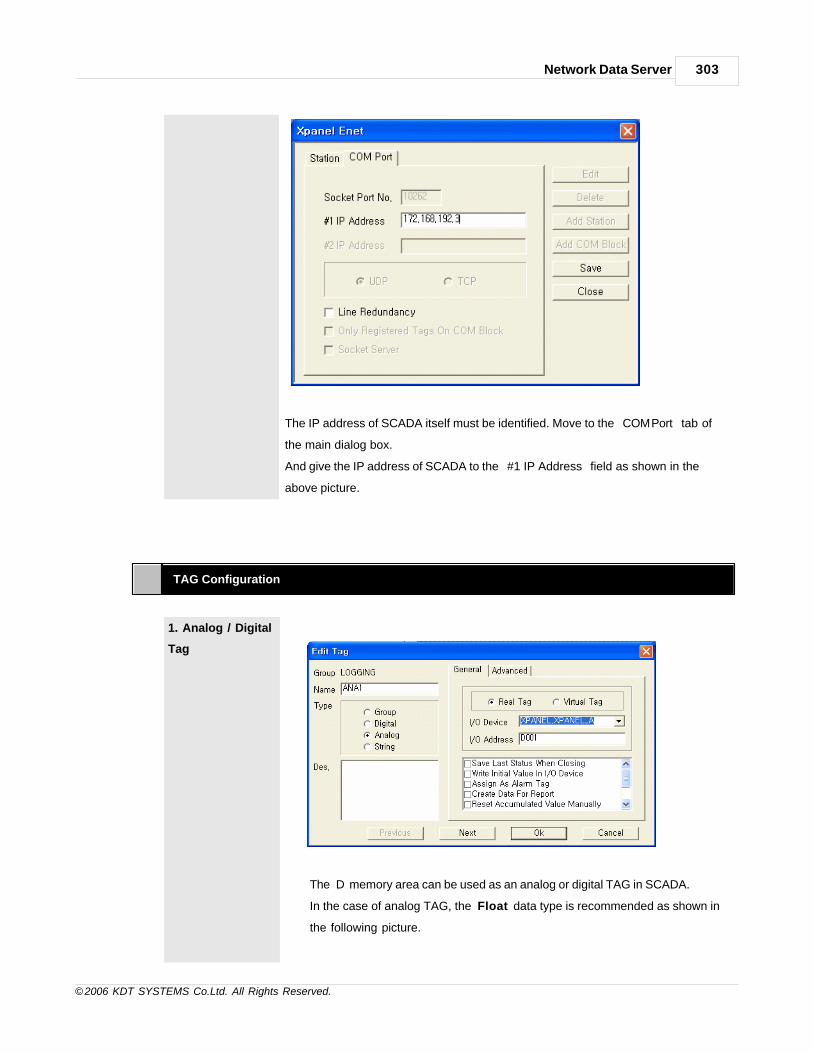
Network Data Server 303
© 2006 KDT SYSTEMS Co.Ltd. All Rights Reserved.
The IP address of SCADA itself must be identified. Move to the “COM Port” tab of
the main dialog box.
And give the IP address of SCADA to the “#1 IP Address” field as shown in the
above picture.
TAG Configuration
1. Analog / Digital
Tag
The ‘D’ memory area can be used as an analog or digital TAG in SCADA.
In the case of analog TAG, the ‘Float’ data type is recommended as shown in
the following picture.

CIMON-Xpanel304
© 2006 KDT SYSTEMS Co.Ltd. All Rights Reserved.
In the case of digital TAG, the value is 1 (true) when the value from Xpanel is
non-zero.
Ensure that the address of TAG is included in the ‘COM Block’ definition.
Otherwise, the data is not monitored normally at online.
2. String TAG
The ‘S’ memory area can be used in the string TAG in SCADA as shown in the
following picture.
Point
1.The maximum length of the string is 80 characters (bytes).
2.Ensure that the address of TAG is included in the ‘COM Block’
definition.
Otherwise, the data is not monitored normally at online.

Top Level IntroThis page is printed before anew top-level chapter starts
Part
XXIII

CIMON-Xpanel306
© 2006 KDT SYSTEMS Co.Ltd. All Rights Reserved.
23 Security
Xpanel provides the security function which protects the secret screen or operation from unauthorized
access.
Every regal user, screen and touch operation in Xpanel has its own privilege level. The 11 privilege levels are
denoted by the number from 0 to 10.
The zero is the lowest level. The operator can see the page or operate the touch zone which has lower
privilege level than his.
See :
· User Registration
· Access Privilege
· User LogOn / LogOff
23.1 User Registration
The Xpanel Designer provides a tool for user security configuration as shown in the following picture.

Security 307
© 2006 KDT SYSTEMS Co.Ltd. All Rights Reserved.
Above user security configuration tool can be opened by ‘Tools’-‘Security’ menu or the icon in
toolbar.
Each user has following properties.
User ID User ID can be any combination of alpha-numeric characters.
The maximum length of ID string is 15 characters.
Level Assign the privilege level of the user.
This level can be a number between 0 and 10. 10 is the most authorized level.
Password Only the numeric characters (‘0’ to ‘9’) can be used as password.
The maximum length of password string is 15 characters.

CIMON-Xpanel308
© 2006 KDT SYSTEMS Co.Ltd. All Rights Reserved.
Description Give a simple description to the user data.
The maximum length of description is 256 characters.
Log On action
Script
This field is not necessarily edited. But, it is very useful when there is a need to do
something at user logon.
Describe the command script in this field.
Please refer to the ‘Script’ section for more information about the ‘command script’.
Log Off Action
Script
This field is not necessarily edited. But, it is very useful when there is a need to do
something at user logoff.
Describe the command script in this field.
Please refer to the ‘Script’ section for more information about the ‘command script’.
23.2 Access Privilege
Xpanel provides the security for page and touch operation.
The user can access the page and touch zone which have the equal or lower privilege level than his.
Page Security

Security 309
© 2006 KDT SYSTEMS Co.Ltd. All Rights Reserved.
The page security can be configured at ‘Page Properties’ window as shown in the above picture.
This window can be opened by ‘Tools’-‘Page Setup’ menu.Every pages are designated a security level
between 0 and 10.
Zero level is the default and lowest level. The user whose privilege level is lower than this cannot access
(open) the page.
Touch Operation Security

CIMON-Xpanel310
© 2006 KDT SYSTEMS Co.Ltd. All Rights Reserved.
Touch zone security configuration is performed based on the above dialog box.
This dialog box is the ‘Object Config’ window. The ‘Touch’ and ‘EntryData’ have the ‘Security’ property page.
Assign a security level to this field.
The user whose privilege level is lower than this cannot access (touch) this object.
23.3 User LogOn / LogOff
Xpanel system’s default user privilege level is zero. The default user privilege level is applied when there is no
logon user in Xpanel system.
To logon Xpanel system, the operator must submit his ID and password though the following window.
This window is popped up by “LogOnWin()” command or function.
Xpanel provides following functions for security manipulation.

Security 311
© 2006 KDT SYSTEMS Co.Ltd. All Rights Reserved.
Please refer to the section of ‘Script’ for more information.
LogOnWin() Pop up the ID and password entry dialog box.
LogOn(“I D”,
“Password”)
Log on without user interface.
This level can be a number between 0 and 10. 10 is the most authorized level.
LogOff() Log off the current user.
The security level of system is returned to the default level (zero).
GetSecurity() Get current security level of system. (0..10)

Top Level IntroThis page is printed before anew top-level chapter starts
Part
XXIV

Script 313
© 2006 KDT SYSTEMS Co.Ltd. All Rights Reserved.
24 Script
The script of Xpanel is very similar with the ‘C’ programming language. Variables can be used in script.
And script provides function call mechanism and supports almost keywords defined in standard ‘C’ language
such as switch-case, for, while, if-else, goto.
All user programmed scripts are executed in multi-thread environment.
Each script is assigned a priority among total 10 levels, such that the execution speed of a script is dependent
on this level. (most high priority = 10, most low priority = 1)
· Uses the ‘C’ language style statement
· All TAGs defined in Xpanel database can be used as variables in script. It does not need additional
definition, symbol or configuration.
That means, values of all TAGs can be referenced or changed in every script program freely.
· Two kinds of variable types are supported, real and string type. Actual type of a variable is decided
automatically during program execution.
But, only one type of value can be used in a script scope. All real type data are processed in 64 bits.
· Does not distinguish capital letters. That is, ‘VAR’ and ‘var’ are the same keyword.
See :
· Structure of Program
· Operator
· Scripts for command and condition
· Statements
· Internal Functions
24.1 Structure of Program
Declaration Part
Declare internal variables and input parameters
Program Part
All program statements can be located here.
Except declarations.
Comments can be located on any place in a script.
A comment must be started by ‘//’ and all strings following this symbol are treated as a comment

CIMON-Xpanel314
© 2006 KDT SYSTEMS Co.Ltd. All Rights Reserved.
string until the end of a line.
Declaration Part
Variable
Declaration
VAR variable_name [, variable_name];
Declare internal variables. The scope of these variables restricted in a declared
script.
The initial value of declared variable is zero. If there is need to declare several
variables, comma(,) can be used between each variable name. This statement can
be used in multiple, until the beginning of program part.
Input
Parameter
Declaration
PARAM 1stparameter [, 2ndparameter … ] ;
This declaration is needed when the program can be called by another program or
command statements.
The order of declaration must be matched with the order of input parameters.
Parameters will be initialized with input parameters from caller. If there is need to
declare multiple parameters,
use comma (,) between parameter names.
This statement can be used in multiple, until the beginning of program part.
Example : MyPgm
VAR a, b;
VAR c;
PARAM p1, p2;
PARAM p3;
Assume that the name of above example program is ‘MyPgm’.
This program can be called by external program or command line as following
statement.
MyPgm(1, 2, 3);
Parameters p1, p2, p3 will be initialized to 1, 2, 3 each. Notice that variables a, b, c
will be initialized to zero.
Program Part
In program part, all the programming statements can be used except variable(VAR) and parameter(PARAM)
declarations.

Script 315
© 2006 KDT SYSTEMS Co.Ltd. All Rights Reserved.
Calculation, storing a data in some variable, function call and many other expressions can be used in a
statement.
Following is a simple example of statements.
Tag_a = Tag_a + 1;
Tag_b = MyPgm(Tag_a, 2, 3);
A statement must be ended by ‘;’ character.
All functions return a value to caller. In the above program example, the returned value will be stored in
Tag_b.
Constants
Following notation is used for each type of constant.
Oc
tal
co
nst
ant
Number characters between 0 and 7 can be used. It must be started by zero. (ex : 01277)
De
ci
ma
l
co
nst
ant
Normal notation is used. (ex : 15, 3.14, 2.45E-12)
He
xa
de
ci
ma
l
co
nst
ant
It must be started with ‘0x’. Alphabet and number character between ‘0’ ‘F’ can be used. (ex : 0xFFFF)
Str
ing
co
A string must be described between two ‘“’. (ex : "string variable " )
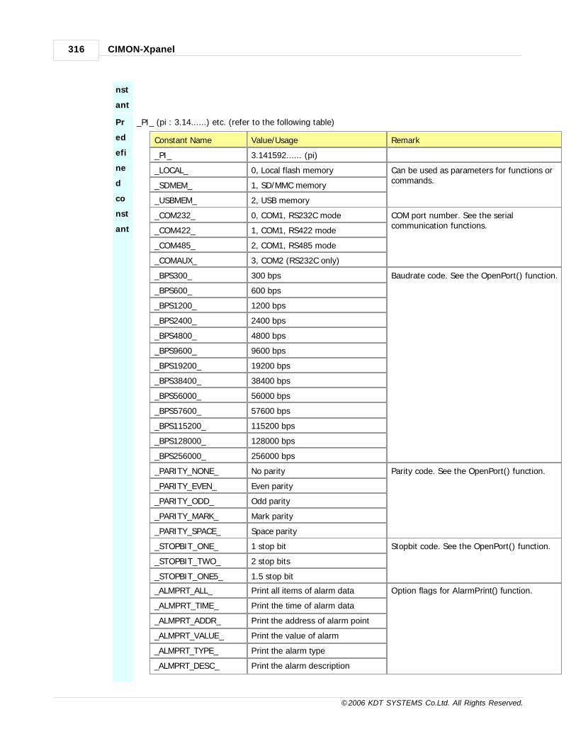
CIMON-Xpanel316
© 2006 KDT SYSTEMS Co.Ltd. All Rights Reserved.
nst
ant
Pr
ed
efi
ne
d
co
nst
ant
_PI_ (pi : 3.14......) etc. (refer to the following table)
Constant Name Value/Usage Remark
_PI_ 3.141592...... (pi)
_LOCAL_ 0, Local flash memory Can be used as parameters for functions orcommands.
_SDMEM_ 1, SD/MMC memory
_USBMEM_ 2, USB memory
_COM232_ 0, COM1, RS232C mode COM port number. See the serialcommunication functions.
_COM422_ 1, COM1, RS422 mode
_COM485_ 2, COM1, RS485 mode
_COMAUX_ 3, COM2 (RS232C only)
_BPS300_ 300 bps Baudrate code. See the OpenPort() function.
_BPS600_ 600 bps
_BPS1200_ 1200 bps
_BPS2400_ 2400 bps
_BPS4800_ 4800 bps
_BPS9600_ 9600 bps
_BPS19200_ 19200 bps
_BPS38400_ 38400 bps
_BPS56000_ 56000 bps
_BPS57600_ 57600 bps
_BPS115200_ 115200 bps
_BPS128000_ 128000 bps
_BPS256000_ 256000 bps
_PARITY_NONE_ No parity Parity code. See the OpenPort() function.
_PARITY_EVEN_ Even parity
_PARITY_ODD_ Odd parity
_PARITY_MARK_ Mark parity
_PARITY_SPACE_ Space parity
_STOPBIT_ONE_ 1 stop bit Stopbit code. See the OpenPort() function.
_STOPBIT_TWO_ 2 stop bits
_STOPBIT_ONE5_ 1.5 stop bit
_ALMPRT_ALL_ Print all items of alarm data Option flags for AlarmPrint() function.
_ALMPRT_TIME_ Print the time of alarm data
_ALMPRT_ADDR_ Print the address of alarm point
_ALMPRT_VALUE_ Print the value of alarm
_ALMPRT_TYPE_ Print the alarm type
_ALMPRT_DESC_ Print the alarm description

Script 317
© 2006 KDT SYSTEMS Co.Ltd. All Rights Reserved.
_UINT_ Unsinged integer Data type options. These definition can beused in the NumToStr() function.
_INT_ Signed integer
_FLOAT_ Floating point value
_HEX_ Hexa-decimal number
_EXP_ Real number with exponent
24.2 Operator
Operators for calculation
The result row of following table assumes that the value of variable ‘A’ is 3 and ‘B’ is 4.
Operator Description Example Result
+ Addition A + B 7
- Subtraction A B -1
* Multiplication A * B 12
/ Division A / B 0.75
% Remainder of division(1) A % B 3
| Bitwise OR(1) A | B 7
& Bitwise AND(1) A & B 0
^ Bitwise XOR(1) A ^ B 7
~ Bitwise Invert(1) ~A 0xFFFFFFFC
<< Bitwise Shift Left A << B 48
>> Bitwise Shift Right A >> B 0
(1) Remainder of division (%) and all bitwise operators are performed with 32 bits integer data.
Logical/Comparative Operators
The result row of following table assumes that the value of variable ‘A’ is 2 (true) and ‘B’ is 0 (false).
Xpanel treats all values except zero as logical TRUE. Only zero is treated as logical FALSE.
When the result of logical operation is TRUE, the value 1 will be returned and stored.
Operator Description Example Result
&& Logical AND A && B 0 (false)
|| Logical OR A || B 1 (true)
! Logical NOT !A 0 (false)
== EQUAL A == B 0 (false)
!= NOT EQUAL A != B 1 (true)

CIMON-Xpanel318
© 2006 KDT SYSTEMS Co.Ltd. All Rights Reserved.
> Big A > B 1 (true)
>= or => Big or Equal A >= B 1 (true)
< Small A < B 0 (false)
<= or =< Small or Equal A <= B 0 (false)
Other Operators
Operator Description Example Result Value
= Store A = B Store the value of B to A, and uses it as a result value.
Store (=) operator can be used in a series. For example :
A = B = C;
In this case, The value of ‘C’ will be stored to ‘A’ and ‘B’. The value of right side of the operator is store in
left side and this value is treated as a return value of the operator. The internal processing order of above
example is :
B <- C
A <- B
Warming
This feature of ‘=’ operator places a bug in program sometimes. That is the confusion with a
comparative operator (==). Following example is illustrating this kind of bug. In this example, a
programmer confused comparative operator(==) with store operator (=). But, XpanelDesigner
cannot detect such error. The reason is, the store operator has a return value and this value can
be used as a logical value in ‘if’ statement. This bug makes unexpected flow of program, and
furthermore, unwanted value will be stored in ‘A’.
//============================
/ /An example of unsolvable program mistake
//============================
IF (A=B) // Compare values of A and B. It is miss-spelling of A=B
...

Script 319
© 2006 KDT SYSTEMS Co.Ltd. All Rights Reserved.
24.3 Scripts for command and condition
In some application, there is a need to use a simple script on graphic object configuration.
For example, to assign a touch operation on an object, one or several command lines must be written in case of
Command Expression action type
(see an example configuration dialog box below). And further more, for making it conditional touch operation, a
conditional expression must be described.
All these conditional expression and command script have the same rules with script programming.
Conditional Expression
The conditional expression always returns only a logical value. A logical value can be one of two values,
TRUE or FALSE.
Xpanel uses the number ‘0’ as the value of logical FALSE, and ‘1’ as the value of logical TRUE.
A logical expression needs some special operators. The logical operators in Xpanel are shown in as following
table.
For more precise information, refer to the section 3.2.
Logical Operator Description Example
&& Logical AND A && B

CIMON-Xpanel320
© 2006 KDT SYSTEMS Co.Ltd. All Rights Reserved.
|| Logical OR A || B
! Logical NOT !A
Comparative Operator Description Example
== EQUAL A == B
!= NOT EQUAL A != B
> Big A > B
>= or => Big or Equal A >= B
< Small A < B
<= or =< Small or Equal A <= B
All logical operators get one or two values for input (operands) and return a logical output value. According
to the above examples, ‘A’ and ‘B’ are those inputs.
The value for logical arithmetic operand is not restricted to only two logical values (TRUE or FALSE). The
input value can be any number.
But, only zero is treated as logical FALSE. All the other values are treated as TRUE.
Comparative operators get two real values for operands and return a logical output value. Those logical
output values can be used in other logical expression.
Here is some examples of conditional expression that can be used in object configuration dialog box.
Conditional Expression Example Remark
(Tag_a != 1) && (Tag_b == 10) If the value of Tag_a is not equal to 1 and the value of Tag_b is
equal to 10, then the expression returns TRUE. Otherwise FALSE.
Sin(Tag_a) == 1 If the sine of Tag_a is 1, then the expression will return TRUE,
otherwise FALSE.
Tag_a < 100 If the value of Tag_a is smaller than 100, then the expression will
return TRUE, otherwise FALSE.
(Tag_a + Tag_b) < (Tag_a + Tag_c) If the sum of Tag_a and Tag_b is smaller than the sum of Tag_a
and Tag_c, then the expression will return TRUE, otherwise
FALSE.
Command Script
The command in Xpanel is not restricted to use only one instruction. A long list of instructions can construct
a command.
That is, the command is a special kind of script program. Within a command script, all kinds of keywords
and functions can be used.
But only one thing, the priority of command script is different with the normal script. When a command

Script 321
© 2006 KDT SYSTEMS Co.Ltd. All Rights Reserved.
script is issued by touch operation or any other method,
it will be executed with top-most priority. For that reason, if a command script has a time consuming loop
inside, all the other process will be halted until the end
of command script. So, especially for calling other function within a command script, the programmer has to
keep in mind that the priority.
If the function has a loop, ‘RunScript’ keyword must be used. This keyword is used for parallel execution.
The calling command script does not wait the termination of called function.
Assume that a programmer wants to call a function named as ‘MyLoop’, and this function has a time
consuming loop.
Then, following instruction must be used, instead of calling directly.
RunScript MyLoop();
Following table shows some typical command script examples.
Command ScriptExample
Remark
Tag_a = 100;
PageOpen(“NewPage”) ;
After changing the value of Tag_a to 100, open a page named as "NewPage "
Tag_b = Tag_b + 1 Increase the value of Tag_b by 1.
Tag_a = 100;
Tag_b = 1;
RunScript MyLoop();
MakCsv(“LogModel”, 1);
After changing the values of Tag_a and Tag_b, invoke MyLoop() script
function.
After that, do not wait the termination of MyLoop(), and create a CSV formatted
file of the ‘LogModel’ on SD memory card.
24.4 Statements
IF-ELSE Statement
WHILE/DO-WHILE Statement
FOR Statement
SWITCH-CASE Statement
GOTO Statement
CONTINUE Keyword
RETURN Keyword
RUNSCRIPT Keyword

CIMON-Xpanel322
© 2006 KDT SYSTEMS Co.Ltd. All Rights Reserved.
24.4.1 IF-ELSE Statement
IF ELSE statement is one of the most frequently using logical decision making statement.
It supports nested IF statement like IF - ELSE IF - ELSE IF... There is no limit on level of nested IF. Else
statement can be omitted.
If (A == 1)
// performed when the value of A is 1
Else
// performed when the value of A is not 1
24.4.2 WHILE/DO-WHILE Statement
These statements are loop statements.
WHILE keyword is followed by a logical expression. During the value of this expression is TRUE, all statements in
WHILE statement are performed repeatedly.
A = 0;
While (A < 10)
// Describe the job should be performed repeatedly
// during the value of logical expression is TRUE
// (This example performs following statement 10 times)
A = A + 1;
WHILE statement makes decision before performing the loop. Such that, statements in loop can never be
performed.
But, DO-WHILE statement performs the loop at least one time. And then makes decision by evaluating logical
expression.
This is a difference between WHILE and DO-WHILE statement.
Do
// Describe the job should be performed repeatedly

Script 323
© 2006 KDT SYSTEMS Co.Ltd. All Rights Reserved.
// during the value of logical expression is TRUE
// (This loop is performed at least 1 time)
While (A < 10); // Semi-colon (;) must be used for marking end of statement.
24.4.3 FOR Statement
It is a little bit complex statement. But, after familiar with this statement, it will be very useful loop statement.
The specialty of this statement is that all expressions for initializing, decision making and post loop processing are
described in one statement line.
Following example shows the same job with the example of WHILE statement presented in former section.
Compare it with WHILE statement.
For (A=0; A<10; A=A+1)
// describe the job to repeat here
FOR keyword is followed by a pair of parenthesis. Expression for initializing, decision making and post loop
processing are described in this parenthesis.
Each expression must be separated by semicolons (‘;’).
FOR ( initializing exp. ; decision making exp. ; post processing exp. )
24.4.4 SWITCH-CASE Statement
This statement is very useful when there are many different processing way depend on a variable or expression.
Each different processing way is described by CASE keyword followed by a constant value. There is no limit on
the number of CASE.
switch (A)
Case 1:
// describe the job to perform when the value of A is 1
Break;
Case 5:
Case 7:
// describe the job to perform when the value of A is 5 or 7
Break;
Default:
// describe the job to perform when A is any other value

CIMON-Xpanel324
© 2006 KDT SYSTEMS Co.Ltd. All Rights Reserved.
// DEFAULT statements can be omitted
Break;
CASE keyword must be followed by a constant value and terminated by a colon (:). A TAG, variable or expression
cannot be used in CASE statement.
DEFAULT statement can be used only once in a SWITCH statement.
It does not need a following constant, and this statement will be performed when there is no matching case.
DEFAULT statement can be omitted if needless.
BREAK keyword in CASE/DEFAULT statement plays role of terminating SWITCH statement.
If there is no BREAK keyword in the progress of program execution until reaches the other CASE/DEFAULT
keyword, the program will continue to execute the
statements in the other CASE/DEFAULT scope. This feature of SWITCH statement is helpful for short and simple
programming, only if it is used intentionally.
24.4.5 GOTO Statement
This statement controls the flow of program execution directly. This statement needs a matching index in a
program scope.
Index is a unique name of a jump destination in a program scope, and it is started with ‘@’ character.
VAR A;
A = 0;
@ComeHere // destination of jump
If (A < 10)
A = A + 1;
Goto ComeHere; // change the flow of program
This example program processes the same job with the previous examples of FOR and WHILE statement section.
The name of index (‘JumpHere’ in the above example) can not be duplicated with variables, tags and program
names.
24.4.6 CONTINUE Keyword
Continue keyword is very useful in loop. When a CONTINUE keyword is met in the progress of a program,
the flow of the program will be moved to the first statement in the loop. This keyword is effective in the loop of
WHILE, DO-WHILE and FOR statement.

Script 325
© 2006 KDT SYSTEMS Co.Ltd. All Rights Reserved.
It is especially useful when there are many decision making in the loop such as IF-ELSE.
Following two program examples process the same job.
While (A<10)
A = A + 1;
If (A < 5)
// Job to do when A is smaller than 5
Else
// Job to do when A is larger than or equal to 5
While (A<10)
A = A + 1;
If (A < 5)
/ / Job to do when A is smaller than 5
Continue;
/ / Job to do when A is larger than or equal to 5
24.4.7 RETURN Keyword
Every program returns a result value to caller. RETURN keyword is used for designating a value to return and
terminating the program.
Following example program processes three input parameters and returns the sum of them to caller.
PARAM p1, p2, p3;
Return p1 + p2 + p3;
Assuming that the name of above program is ‘MyPgm’, it can be called from another program as following
program line.
RtnValue = MyPgm(1, 2, 3);

CIMON-Xpanel326
© 2006 KDT SYSTEMS Co.Ltd. All Rights Reserved.
After ‘MyPgm’ call, a value of 6 will be stored in ‘RtnValue’.
24.4.8 RUNSCRIPT Keyword
When a program calls another program, the caller program will be stalled until when the called program
terminates.
RUNSCRIPT keyword provides another way of invoking other program. It does not make stall the caller program.
After invoke another program, the caller program continues it’s own job. As a result, both programs will run in
parallel and this is the feature of multi-threading.
Following example shows the multi-threading feature by using RUNSCRIPT keyword. It is assuming that the name
of another program is ‘NewThread’.
If(A == 0)
RunScript NewThread(); // Invoke another program (NewThread)
A = A + 1; // Continues next job without stalling.
24.5 Internal Functions
IN THIS TOPIC :
Trigonometric Functions Other Mathematic Functions Special Functions
* R1, R2, .... : Real type input parameters * S1, S2, .... : Stringtype
input parameters
Trigonometric Functions
Function DescriptionRetur
n
Sin(R1) Sine Real
Cos(R1) Cosine Real
Tan(R1) Tangent Real
Asin(R1) Arc Sine Real
Acos(R1) Arc Cosine Real
Atan(R1) Arc Tangent Real
Sinh(R1) Hyperbolic Sine Real
Cosh(R1) Hyperbolic Cosine Real

Script 327
© 2006 KDT SYSTEMS Co.Ltd. All Rights Reserved.
Tanh(R1) Hyperbolic Tangent Real
Atan2(R1, R2) Arc Tangent, Atan(R1/R2)와 동일 Real
Other Mathematic Functions
Function DescriptionRetur
n
Log(R1) Calculates logarithm Real
Log10(R1) Calculates logarithm Real
Ceil(R1) Calculates the ceiling of a value Real
Floor(R1) Calculates the floor of a value Real
Abs(R1) Calculates the absolute value Real
Sqrt(R1) Calculates the square value Real
Rand() Generates a pseudorandom number Real
Fmod(R1, R2) Calculates the floating-point remainder (R1/R2) Real
Special Functions
Function Description Return
PageOpen(S1) Opens a new page named as S1
PageClose(S1) Closes an opened page
FrameOpen(S1) Opens a new frame named as S1
StringTable(R1, R2) Get a string from string table
(R1=Group No., R2=String No.)
String
GetTime(R1) Get a clock data (R1 : type of data) Real
TimeStr(R1, S2) Assemble a string of time
R1 : clock value from GetTime(0)
S2 : Format string
String
RunApp(S1, S2) Executes an external program
S1 : Program name
S2 : Program input parameter
MakeCsv(S1, R2) Makes a CSV formatted log file in SD memory
S1 : Name of log model
R2 : Number of block (0=current logging block)
MakeCsvUsb(S1, R2) Makes a CSV formatted log file in USB memory

CIMON-Xpanel328
© 2006 KDT SYSTEMS Co.Ltd. All Rights Reserved.
S1 : Name of log model
R2 : Number of block (0=current logging block)
MakeLogCsv(S1, R2, R3) Makes a CSV formatted log file
S1 : Name of log model
R2 : Number of block (0=current logging block)
R3 : Storage media code (0=local, 1=SD/MMC, 2=USB)
DataLog(S1, R2) Start / Stop the data logging
S1 : Name of log model
R2 : 0=Stop, 1=Start
RcpDownload(S1, R2) Read a group of recipe data from file, and download it to
device
S1 : Name of recipe model
R2 : Zero based group number
RcpUpload(S1, R2) Upload the specified recipe group data from device, and
store it to file.
S1 : Name of recipe model
R2 : Zero based group number
RcpStop(S1) Stop and terminate the processing job of specified recipe
model.
S1 : Name of recipe model
RcpFileStore(S1, R2) Stores the recipe data to the file.
S1 : Name of recipe model
R2 : Zero based group number
RcpFileRead(S1, R2) Read the recipe data from file.
S1 : Name of recipe model
R2 : Zero based group number
RcpMemDown(S1) Download the current recipe data to device.
S1 : Name of recipe model
RcpMemUp(S1) Upload the recipe data from device.
S1 : Name of recipe model
RcpCsvRd(S1, S2, R3) Read the recipe data from CSV formatted file.
S1 : Name of recipe model
S2 : File name
R3 : File location (0=local, 1=SD/MMC, 2=USB)
RcpCsvWr(S1, S2, R3) Create a CSV formatted file with current recipe group data in
memory.
S1 : Name of recipe model
S2 : File name
R3 : File location (0=local, 1=SD/MMC, 2=USB)

Script 329
© 2006 KDT SYSTEMS Co.Ltd. All Rights Reserved.
RcpConfig() Pops up a dialog box for recipe data manipulation.
TrendCsvWr(S1, R2) Make a CSV formatted file from trend data.
S1 : Trend name
R2 : File location (0=local, 1=SD/MMC, 2=USB)
ScrCapture(S1, R2) Make a BMP formatted file of current screen
S1 : BMP file name.
R2 : File location (0=local, 1=SD/MMC, 2=USB)
Sleep(R1) Put delay on the script program
R1 : delay time in milli-second
HardCopy() Print out the current screen image to USB printer.
OpenPort (R1, R2, R3, R4,
R5)
Open a serial port for communication.
R1 : Port number (predefined as _COMxxx_)
R2 : Baudrate code (predefined as _BPSxxxx_)
R3 : Parity code (predefined as _PARITY_xxx_)
R4 : Data bits (7 or 8)
R5 : Stop bits code (predefined as _STOPBIT_xxx_)
1:OK.
2:Error
ClosePort(R1) Close a serial port.
R1 : Port number (predefined as _COMxxx_)
1:OK.
2:Error
SendByte(R1, R2) Transmit a byte datum though the R1 port.
R1 : Port number (predefined as _COMxxx_)
R2 : A datum to transmit. (0..255)
1:OK.
2:Error
SendString(R1, S2) Transmit a string data though the R1 port.
R1 : Port number (predefined as _COMxxx_)
S2 : A string to transmit.
1:OK.
2:Error
ReceiveByte(R1, R2) Receive a byte datum though the R1 port.
R1 : Port number (predefined as _COMxxx_)
R2 : Time-out in milli-second.
Receiveddata orerror
StrToNum(S1, R2) Converts a numeric string to a value
S1 : Numeric string
R2 : Base (0, 2..36)
Converte
d Value
NumToStr(R1, R2, R3) Converts a numeric data to a string
R1 : Numeric value
R2 : Value type
S3 : Format string
Converte
d Value
LogOn(S1, S2) A user log on
S1 : User ID
S2 : Password
1: OK
0: Error
LogOff() A user log off. 1: OK
0: Error

CIMON-Xpanel330
© 2006 KDT SYSTEMS Co.Ltd. All Rights Reserved.
LogOnWin() Open a user log on window.
GetSecurity() Gets the current security level (0..10) Security
Level
OpenConfigWin() Open the online configuration tool window.
SoftKeyboard(R1, R2, R3) Show or hide the software keyboard
AlarmPrint(R1, R2, R3, R4,
R5)nt(R1, R2, R3, R4, R5)
Print a alarm list of designated group.
R1 : Group number (1..10)
R2 : Number of alarm to print
R3 : Time/Date format code
R4 : Font size
R5 : Option flags (_ALMPRT_xxxx_)
AlaramCSVWr(R1, S2, R3,
R4, R5)
Create a CSV formatted file with designated alarm group.
R1 : Alarm group number
S2 : File name
R3 : Time/Date format code
R4 : Option flags (_ALMPRT_xxxx_)
R5 : File location (0=local, 1=SD/MMC, 2=USB)
TouchCalib() Opens the touch panel calibration window.
ClearAlarmLog(R1) Clear all messages listed in the designated alarmgroup (summary)R1 : Alarm group number
AddMessage(R1, S2) Add a new string to the scroll message window.R1 : String IDS2 : A string to add.
RemoveMessage(R1) Remove a string which was already registered to thescroll messagewindow by AddMessage() function.R1 : String ID which was designated on AddMessage()function call.
RcpGetSysMem(S1, R2) Copy/move a block of system memory to the memoryof the recipe group data.S1 : Name of recipe modelR2 : System memory address
RcpSetSysMem(S1, R2) Copy/move the recipe group data in memory to systemmemory.S1 : Name of recipe modelR2 : System memory address
SetSysMem(R1, R2) Set a value to the designated system memory.R1 : System memory addressR2 : Value to set
GetSysMem(R1) Get a value from the designated system memory.R1 : System memory address
Real
SysMemMove(R1, R2, R3) Move a block of data within the system memory.R1 : System memory address (source)R2 : System memory address (destination)

Script 331
© 2006 KDT SYSTEMS Co.Ltd. All Rights Reserved.
R3 : Number of data to move
SysMemFill(R1, R2, R3) Fill a block of system memory with the designatedvalue.R1 : System memory addressR2 : Fill valueR3 : Number of data to fill
LcdBrightUp() LCD brightness control (lighten)
LcdBrightDown() LCD brightness control (darken)
LcdBacklight(R1) LCD backlight control (turn on / off)
StaticBeepCtrl(R1) Turn on or turn off beep on Xpanel.
R1 : Beep on / off value (0: Off, 1: On)
SetSpeed(R1) Script process speed control.
R1 : Speed value (0: Normal, Another value: High)
SetDate(R1,R2,R3) Change date on Xpanel.
SetTime(R1) Change time on Xpanel
24.5.1 PageOpen(S1)
PageOpen(S1) Opens a new page
[S1] new page name (without extension)
Opens a new screen page. If the new page has no special style, then previous page or
frame will be closed automatically. Otherwise, according to the style of the new page,
following result can be shown.
A pop-upstyle
If a new page has a style of pop-up, current page does not affected by this new page.
The new page pops up over current page.
A page forframe
This kind of page has a position number in a frame. For open this page, the frame has
to be opened in advance. The old page which has the same position number in the
frame will be replaced by this page automatically.
24.5.2 FrameOpen(S1)
FrameOpen(S1) Opens a new frame
[S1] new frame name (without extension)
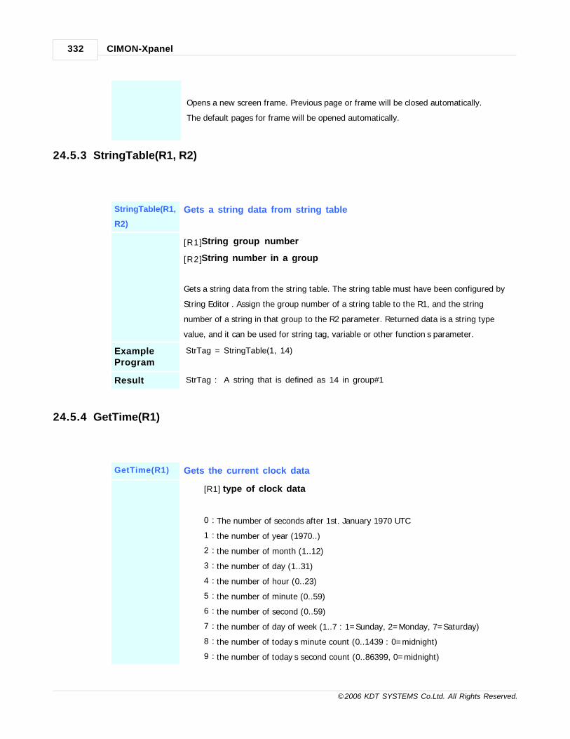
CIMON-Xpanel332
© 2006 KDT SYSTEMS Co.Ltd. All Rights Reserved.
Opens a new screen frame. Previous page or frame will be closed automatically.
The default pages for frame will be opened automatically.
24.5.3 StringTable(R1, R2)
StringTable(R1,
R2)
Gets a string data from string table
[R1] String group number
[R2] String number in a group
Gets a string data from the string table. The string table must have been configured by ‘
String Editor’. Assign the group number of a string table to the R1, and the string
number of a string in that group to the R2 parameter. Returned data is a string type
value, and it can be used for string tag, variable or other function’s parameter.
ExampleProgram
StrTag = StringTable(1, 14)
Result StrTag : “A string that is defined as 14 in group#1”
24.5.4 GetTime(R1)
GetTime(R1) Gets the current clock data
[R1] type of clock data
0 : The number of seconds after 1st. January 1970 UTC
1 : the number of year (1970..)
2 : the number of month (1..12)
3 : the number of day (1..31)
4 : the number of hour (0..23)
5 : the number of minute (0..59)
6 : the number of second (0..59)
7 : the number of day of week (1..7 : 1=Sunday, 2=Monday, 7=Saturday)
8 : the number of today’s minute count (0..1439 : 0=midnight)
9 : the number of today’s second count (0..86399, 0=midnight)

Script 333
© 2006 KDT SYSTEMS Co.Ltd. All Rights Reserved.
24.5.5 TimeStr(R1, S2)
TimeStr(R1,
S2)
Makes a string of clock
[R1] Clock data (It can be acquired by GetTime(0) function call)
The number of seconds after 1st. January 1970 UTC
[S2] Format string (can include following symbols)
%A : Full name of weekday (ex : Sunday)
%a : Abbreviation of weekday (ex : Sun)
%B : Full name of month (ex : January)
%b : Abbreviation of month (ex : Jan)
%d : date (1..31)
%H : Hour in 24-hour format (0..23)
%I : Hour in 12-hour format (1..12)
%m : Month (1..12)
%M : Minute (0..59)
%p : A.M. / P.M. indicator for 12-hour format (A.M., P.M.)
%S : Second (0..59)
%y : Number of year without century (00..99)
%Y : Number of year with century (ex : 2006)
ExampleProgram
CurTime = GetTime(0);
StrTag = TimeStr(CurTime, "%Y/%m/%d/ %H:%M:%S");
Result StrTag : “A string that is defined as 14 in group#1”
24.5.6 RunApp(S1, S2)
RunApp(S1,
S2)
Executes an external application program
[ S 1 ] Application program name with path and extension
[ S 2 ] Input parameter string for the application program

CIMON-Xpanel334
© 2006 KDT SYSTEMS Co.Ltd. All Rights Reserved.
Executes an external application program.
This program can be not only system included program, also user programmed
program.
Example
ProgramRunApp(“Ping.EXE”, “- t 100.100.100.1”) ;
Result Ping test screen will be popped up when this command or program is issued.
24.5.7 MakeCsv(S1, R2)
MakeCsv(S1,
R2)Makes a CSV Formatted log file in SD memory
[ S 1 ] Log model name
[R2 ] Block number of designated log model
Converts the designated block file to a CSV formatted file and stores it on the SD/MMC
memory.
A SD/MMC memory has to be plugged before the issuing of this function. A CSV file will
be written in the folder ‘Xpanel’ of the SD/MMC memory card. The CSV file name is
assembled with the date and time log started, and it’s from original block file.
(YYMMDD HHmmSS.CSV)
When the R2 parameter is zero, this function will try to convert the current log
proceeding (uncompleted) block file. If the logging task of designated model is not
running at the moment of the function call, no CSV file will be created.
The parameter R2 can be designated up to the ‘Maximum Block No.’ which should have
been set in the model configuration dialog box. When the R2 parameter is 1, this
function will try to convert the most recently log completed block file.
Obsolete : See the 'MakeLogCsv(S1, R2, R3)' function below.
Example
ProgramMakeCsv(“ModelName”, 1);

Script 335
© 2006 KDT SYSTEMS Co.Ltd. All Rights Reserved.
24.5.8 MakeCsvUsb(S1, R2)
MakeCsvUsb
(S1, R2)Makes a CSV Formatted log file in USB memory
[ S 1 ] Log model name
[R2 ] Block number of designated log model
Converts the designated block file to a CSV formatted file and stores it on the USB
memory.
An USB memory has to be plugged before the issuing of this function. A CSV file will be
written in the folder ‘Xpanel’ of the USB memory card. The CSV file name is assembled
with the date and time log started, and it’s from original block file. (YYMMDD
HHmmSS.CSV)
When the R2 parameter is zero, this function will try to convert the current log
proceeding (uncompleted) block file. If the logging task of designated model is not
running at the moment of the function call, no CSV file will be created.
The parameter R2 can be designated up to the ‘Maximum Block No.’ which should have
been set in the model configuration dialog box. When the R2 parameter is 1, this
function will try to convert the most recently log completed block file.
Obsolete : See the 'MakeLogCsv(S1, R2, R3)' function below.
24.5.9 MakeLogCsv(S1,R2,R3)
MakeLogCsv(S1,
R2,R3)Makes a CSV formatted log file.
[ S 1 ] Log model name
[R2 ] Block number of designated log model.
[R3 ] Storage type (_LOCAL_, _SDMEM_, _USBMEM_
Converts the designated block file to a CSV formatted file and stores it on the
designated storage (R3).

CIMON-Xpanel336
© 2006 KDT SYSTEMS Co.Ltd. All Rights Reserved.
Storage Media Number Symbol CSV file location
Internal FlashDisk
0 _LOCAL_ \ \XPane l \LOG\ [modelname] \
SD/MMC 1 _SDMEM_ \ \ L O G \ [ m o d e l n a m e ] \
USB 2 _USBMEM_ \ \ L O G \ [ m o d e l n a m e ] \
The CSV file name is assembled with the start date and time of log data, and it’s
from original block file. (YYMMDD HHmmSS.CSV) When the R2 parameter is zero,
this function will try to convert the uncompleted block file which is under logging. If
the logging task of designated model is not running at the moment of the function
call, no CSV file will be created. The parameter R2 can be designated up to the
‘Maximum Block No.’ which should have been set in the model configuration dialog
box. When the R2 parameter is 1, this function will try to convert the most recently
log completed block file.
This function includes all functionalities of “MakeCsv()” and “MakeCsvUsb()”
functions. This function is strongly recommended for creating a CSV formatted file
from log data instead of using the two obsolete functions.
Example
Program MakeLogCsv(“ModelName”, 1, _LOCAL_);
Result A CSV file will be created on the local flash memory with the data from the most
recently log completed block file.
24.5.10DataLog(S1, R2)
DataLog(S1,
R2)Data logging start / stop
[ S 1 ] Log model name
[R2 ] 0 or 1 (0 : STOP, 1 : START)
This function is effective only on the log model of external call start type. Models with
other start type such as periodic, trigger tag, enable tag or on time are not affected by
this function.
If the R2 parameter is 0, the designated logging task will be terminated. Otherwise, the
logging task will be invoked by this function. This function treats the non-zero value of
R2 as 1.
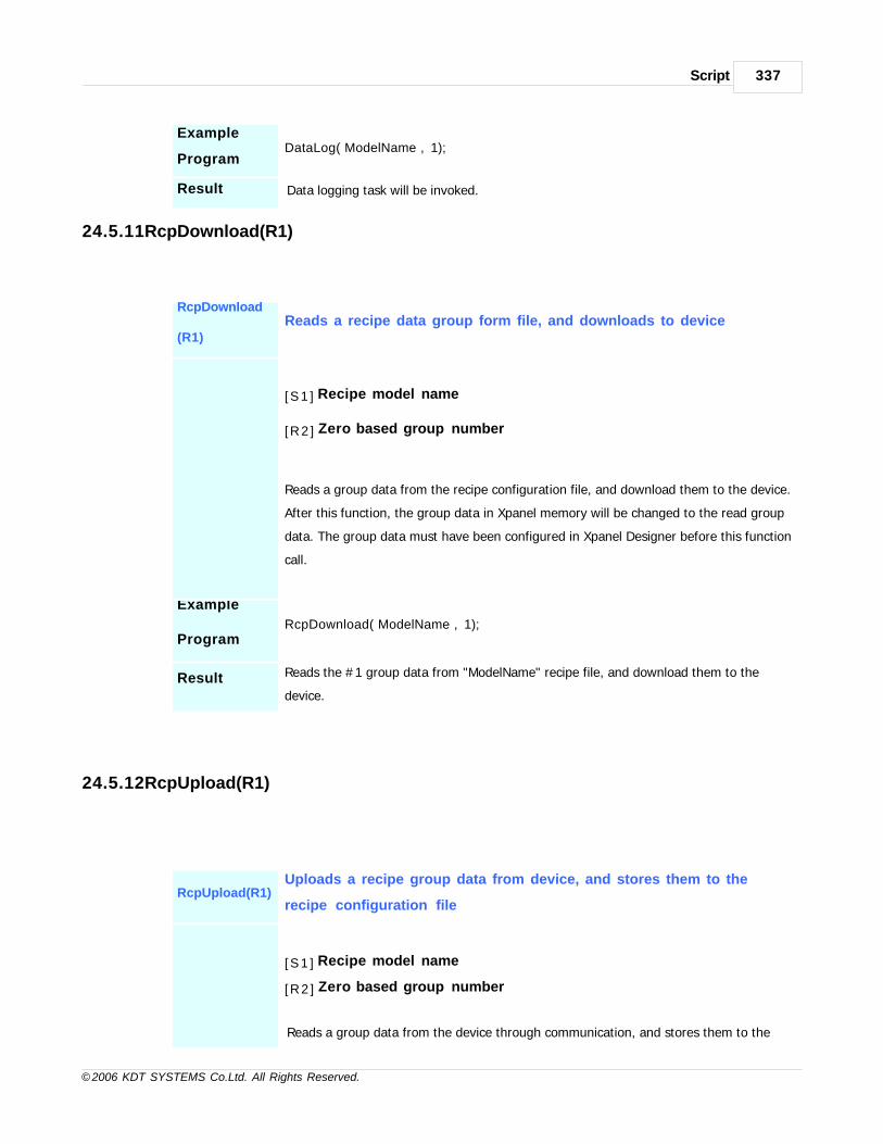
Script 337
© 2006 KDT SYSTEMS Co.Ltd. All Rights Reserved.
Example
ProgramDataLog(“ModelName”, 1);
Result Data logging task will be invoked.
24.5.11RcpDownload(R1)
RcpDownload
(R1)
Reads a recipe data group form file, and downloads to device
[ S 1 ] Recipe model name
[R2 ] Zero based group number
Reads a group data from the recipe configuration file, and download them to the device.
After this function, the group data in Xpanel memory will be changed to the read group
data. The group data must have been configured in Xpanel Designer before this function
call.
Example
ProgramRcpDownload(“ModelName”, 1);
Result Reads the #1 group data from "ModelName" recipe file, and download them to the
device.
24.5.12RcpUpload(R1)
RcpUpload(R1)Uploads a recipe group data from device, and stores them to the
recipe configuration file
[ S 1 ] Recipe model name
[R2 ] Zero based group number
Reads a group data from the device through communication, and stores them to the

CIMON-Xpanel338
© 2006 KDT SYSTEMS Co.Ltd. All Rights Reserved.
recipe configuration file. After this function, the group data in Xpanel memory will be
changed to the read group data. The designated recipe group must have been declared
in Xpanel Designer before this function call.
Example
ProgramRcpUpload(“ModelName”, 2);
ResultUploads the recipe data from the device, and stores them to the group #2 of
"ModelName" recipe file.
24.5.13RcpStop(S1)
RcpStop(S1) Stops and terminates the recipe operations
[ S 1 ] Recipe model name
This function terminates any job related with designated name of recipe model. For
example, if download process is proceeding through communication when this function
is issued, then the communication will be stopped and terminated. Be careful to use
this function, because there is a possibility of storing unwanted data group in file or
device. Use this function only when there is a unrecoverable network or device
breakdown.
24.5.14RcpFileStore(S1, R2)
RcpFileStore
(S1, R2)
Stores the current recipe data in memory to the file
[ S 1 ] Recipe model name
[R2 ] Zero based group number
This function stores a group data in memory of Xpanel to the configuration file.
The designated recipe group must have been declared in Xpanel Designer before this
function call.

Script 339
© 2006 KDT SYSTEMS Co.Ltd. All Rights Reserved.
24.5.15RcpFileRead(S1, R2)
RcpFileRead
(S1, R2)
Stores the current recipe data in memory to the file
[ S 1 ] Recipe model name
[R2 ] Zero based group number
This function reads a group data in the configuration file and stores them to the
memory of Xpanel. The designated recipe group must have been configured by Xpanel
Designer, or stored by other way before this function call..
24.5.16RcpMemDown(S1)
RcpMemDown
(S1)
Downloads a group of recipe data in memory to the device
[ S 1 ] Recipe model name
This function downloads a group data in memory of Xpanel to the device.
The group data must have been loaded in memory by other way before this function
issue.
24.5.17RcpMemUp(S1)
RcpMemUp(S1) Uploads a group of recipe data to memory from the device
[ S 1 ] Recipe model name
This function uploads a group data in device to the memory of Xpanel.
The uploaded group data can be processed by other functions or recipe tool window.

CIMON-Xpanel340
© 2006 KDT SYSTEMS Co.Ltd. All Rights Reserved.
24.5.18RcpCsvRd(S1, S2, R3)
Rc
pC
sv
Rd
(S1
,
S2,
R3)
Reads a group of recipe data from CSV formatted file
[ S1] Recipe model name
[ S 2 ] CSV file name (without extension and path)
[R3 ] CSV file location code (0 : local, 1 : SD/MMC, 2 : USB)
This function reads a group of data from CSV formatted file and stores them to the memory of Xpanel.
The CSV formatted file must have information about the number of data it has.
This number must be located in the top most of data list, and the number must be matched with the one
that assigned
in the recipe model setup dialog box.

Script 341
© 2006 KDT SYSTEMS Co.Ltd. All Rights Reserved.
The second parameter S2 is a name of CSV file to read. There is no need to specify the extension. But,
the path of the CSV file location must be root folder of each storage media.
The third parameter R3 indicates the storage media where the CSV file was stored. It can be one of
three numbers, 0 to 2. Xpanel provides predefined constants for them. That is, following constant
symbols can be used as parameter R3 instead of number.
Media Number Symbol CSV file location
Internal Flash Disk 0 _LOCAL_ Xpanel
SD/MMC 1 _SDMEM_ Root
USB 2 _USBMEM_ Root
Ex
a
m
pl
e
Pr
og
ra
m
RcpCsvRd(“ModelName”, “RcpFileName”, _SDMEM_);
Re
sul
t
Reads a CSV formatted file named as "RcpFileName.CSV" in SD/MMC memory card, and stores the data
in memory of Xpanel.
24.5.19RcpCsvWr(S1, S2, R3)
RcpCsvWr(S1,
S2, R3)Create a CSV formatted file with current recipe group data in memory.
[ S 1 ] Recipe model name
[ S 2 ] CSV file name (without extension and path)
[R3 ] CSV file location code (0 : local, 1 : SD/MMC, 2 : USB)
This function creates a CSV formatted file with a group data in XPanel’s memory. The
created CSV formatted file includes a number which represents how many number of
recipe group data are followed as shown in the following picture.
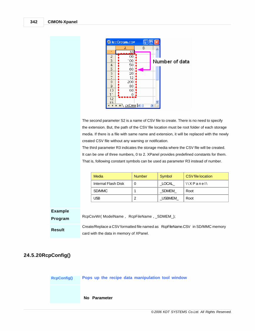
CIMON-Xpanel342
© 2006 KDT SYSTEMS Co.Ltd. All Rights Reserved.
The second parameter S2 is a name of CSV file to create. There is no need to specify
the extension. But, the path of the CSV file location must be root folder of each storage
media. If there is a file with same name and extension, it will be replaced with the newly
created CSV file without any warning or notification.
The third parameter R3 indicates the storage media where the CSV file will be created.
It can be one of three numbers, 0 to 2. XPanel provides predefined constants for them.
That is, following constant symbols can be used as parameter R3 instead of number.
Media Number Symbol CSV file location
Internal Flash Disk 0 _LOCAL_ \ \ X P a n e l \
SD/MMC 1 _SDMEM_ Root
USB 2 _USBMEM_ Root
Example
ProgramRcpCsvWr(“ModelName”, “RcpFileName”, _SDMEM_);
ResultCreate/Replace a CSV formatted file named as “RcpFileName.CSV” in SD/MMC memory
card with the data in memory of XPanel.
24.5.20RcpConfig()
RcpConfig() Pops up the recipe data manipulation tool window
No Parameter

Script 343
© 2006 KDT SYSTEMS Co.Ltd. All Rights Reserved.
This function pops up a tool window for recipe. This tool window shows the current
recipe data in memory. And it provides some tools for editing individual datum in a
group, changing current group, saving the current data to file and up/downloading the
recipe data from/to the device. (Please refer to the ‘Recipe’ section for more
information)
24.5.21TrendCsvWr(S1, R2)
TrendCsvWr
(S1, R2))Makes and stores a CSV formatted file from trend
[ S 1 ] Trend name
[R2 ] CSV file location code (0 : local, 1 : SD/MMC, 2 : USB)
This function makes a CSV formatted file from a trend object. Output CSV file can be stored
in not only local flash disk, but external memory card. Next screen capture shows an example
of output CSV file.
The name of generated CSV file has the format of "Trendname_MMDDHHmmSS.CSV
". This name is generated from trend name, date and time.
The second parameter R2 indicates the storage media where the CSV file will be stored. It
can be one of three numbers, 0 to 2. Xpanel provides predefined constants for them. That is,
following constant symbols can be used as parameter R2 instead of number.

CIMON-Xpanel344
© 2006 KDT SYSTEMS Co.Ltd. All Rights Reserved.
Media Number Symbol CSV file location
Internal Flash Disk 0 _LOCAL_ Xpanel
SD/MMC 1 _SDMEM_ Root
USB 2 _USBMEM_ Root
Example
ProgramTrendCsvWr(“TrendExample”, _SDMEM_);
Result
Makes a CSV formatted file on SD/MMC cards. The data will be taken from the
"TrendExample" trend data.
24.5.22ScrCapture(S1, R2)
ScrCapture(S1,
R2)Captures current screen and makes a BMP format image file
[ S 1 ] Seed for making BMP file name
[R2 ] BMP file location code (0 : local, 1 : SD/MMC, 2 : USB)
This function captures current screen display and makes a BMP formatted image file. The name
of BMP file will be made with the seed string of S1 parameter and time. File name format is "
Seedname_HHmmSS.BMP".
The second parameter R2 indicates the storage media for generated BMP file. It can be one of
three numbers, 0 to 2. Xpanel provides predefined constants for them. That is, following
constant symbols can be used as parameter R2 instead of number.
Media Number Symbol CSV file location
Internal Flash Disk 0 _LOCAL_ Xpanel
SD/MMC 1 _SDMEM_ Root
USB 2 _USBMEM_ Root
Example
ProgramScrCapture(“Mybmp”, _SDMEM_);
Result Makes a CSV formatted file on SD/MMC cards. The data will be taken from the "TrendExample"

Script 345
© 2006 KDT SYSTEMS Co.Ltd. All Rights Reserved.
trend data.
24.5.23Sleep(R1)
Sleep(R1) Ruts some delay to the current script program
[R1 ] Delay time in milli-seconds
This function suspends the execution of the current script program for a specified
interval (R1).
The interval must be specified in milli-seconds unit.
24.5.24HardCopy()
HardCopy() Prints out the current screen image to USB printer
This function prints out the screen image to USB printer.
The printer must support PCL (Printer Control Language).
24.5.25OpenPort(R1, R2, R3, R4, R5)
OpenPort
(R1, R2, R3, R4,
R5)
Opens the R1 serial port for communication.
[R1 ] COM port number (use the predefined symbol. _COMxxxx_)
[R2 ] Baudrate (use the predefined symbol, _BPSxxxx_)
[R3 ] Parity (use the predefined symbol, _PARITY_xxx)
[R4 ] Data bits (7 or 8)
[R5 ] Stop bits (use the predefined symbol, _STOPBIT_xxx)
This function opens a serial port for communication. Xpanel has two serial

CIMON-Xpanel346
© 2006 KDT SYSTEMS Co.Ltd. All Rights Reserved.
communication ports (COM1 and COM2). The COM1 port can be configured as one of
three modes (RS232C, RS422 and RS485). Predefined symbols for R1, R2, R3 and R5
parameters are provided, please refer to the ‘Constants’ section of this manual.
The port which is being used for device communication or already opened, cannot be
opened by this function. Before calling this function, ensure that the designated port is
not being used in device driver. And also, if the port has been opened and used
previously before this function call, ensure that it was closed by ClosePort() function. If
there is an error for opening a port, this function returns zero (0). When the port was
opened successfully, this function returns non-zero value.
Example
Program
OpenPort(_COM485_, _BPS19200_, _PARITY_NONE_, 8, _STOPBIT_ONE_);
SendByte(_COM485_, 2);
……
ClosePort(_COM485_);
Result
Opens the COM1 port for communication if it is available for using.
The port will be set up as RS485 communication mode, 19200 bps, no parity, 8 data
bits and 1 stop bit.
24.5.26ClosePort(R1)
ClosePort(R1) Closes the R1 serial port which has been opened
[R1 ] COM port number (use the predefined symbol. _COMxxxx_)
This function closes the designated serial port which has been opened by OpenPort()
function.
Predefined symbols for R1 parameter are provided, please refer to the ‘Constants’
section of this manual.
Example
Prog
OpenPort(_COM485_, _BPS19200_, _PARITY_NONE_, 8, _STOPBIT_ONE_);
SendByte(_COM485_, 2);
……

Script 347
© 2006 KDT SYSTEMS Co.Ltd. All Rights Reserved.
ClosePort(_COM485_);
Result Closes the COM1 port.
24.5.27SendByte(R1, R2)
SendByte(R1,
R2)Transmits a string (S2) through the R1 port
[R1 ] COM port number (use the predefined symbol. _COMxxxx_)
[R2 ] A datum to transmit. The value can be between 0 and 255.
This function transmits a datum through the designated serial port (R1) which has
been opened by OpenPort() function. Predefined symbols for R1 parameter are
provided, please refer to the ‘Constants’ section of this manual.
The R2 parameter must be a byte datum, between 0 (0x00) and 255 (0xFF). If a value
larger than 255 (0xFF) was designated to the R2, the upper bytes will be discarded and
only the lower 1 byte datum will be transmitted. For example, if the value 0x1234 was
assigned to the R2, the 0x34 will be transmitted.
Ensure that the R1 port must have been opened by OpenPort() function, before calling
this function.
Example
Program
OpenPort(_COM485_, _BPS19200_, _PARITY_NONE_, 8, _STOPBIT_ONE_);
SendByte(_COM485_, 2);
……
Result Transmits a byte datum 2 (0x02) through the COM1 port in RS485 mode.
24.5.28SendString(R1, S2)
SendString(R1,
S2)Transmits a string (S2) through the R1 port

CIMON-Xpanel348
© 2006 KDT SYSTEMS Co.Ltd. All Rights Reserved.
[R1 ] COM port number (use the predefined symbol. _COMxxxx_)
[ S 2 ] A string to transmit. The maximum length of the string is 255
characters
This function transmits a string through the designated serial port (R1) which has been
opened by OpenPort() function. Predefined symbols for R1 parameter are provided,
please refer to the ‘Constants’ section of this manual. The S2 parameter must be a
string or string tag.
Ensure that the R1 port must have been opened by OpenPort() function, before calling
this function.
Example
Program
OpenPort(_COM485_, _BPS19200_, _PARITY_NONE_, 8, _STOPBIT_ONE_);
SendString(_COM485_, “This string will be transmitted.”) ;
……
ResultRS485 통신을 하는 COM1를 통해 문자열데이터 “This string will be transmitted.”를 전송
합니다 .
24.5.29ReceiveByte(R1, R2)
ReceiveByte
(R1, R2)Recives a byte datum from R1 port
[R1] COM port number (use the predefined symbol. _COMxxxx_)
[R2 ] Timeout in milli-second
This function waits and receives a byte datum from designated port (R1) which has
been opened by OpenPort() function. If there is no datum until when the timeout (R2)
expires, this function will return 256 (0x100). Otherwise, a received byte datum will be
returned. (0 to 255)
R1 parameter specifies the COM port for receiving data, and predefined symbols can be
used for this parameter. Please refer to the ‘Constants’ section of this manual.
Ensure that the R1 port must have been opened by OpenPort() function, before calling

Script 349
© 2006 KDT SYSTEMS Co.Ltd. All Rights Reserved.
this function.
Example
Program
VAR RxData;
OpenPort(_COM485_, _BPS19200_, _PARITY_NONE_, 8, _STOPBIT_ONE_);
RxData = RecieveByte(_COM485_, 1000);
If(RxData < 256)
……
ResultReceives a datum from the COM1 port in RS485 mode, and stores the datum in ‘RxData’
variable..
24.5.30StrToNum(S1, R2)
StrToNum(S1,
R2)Convers a numeric string to a value
[ S 1 ] Numeric string. It can be the following form when the base (R2)
is 10 :
[sign][digit][.digit][d|D|e|E[sign]digit]
The sign is either plus (+) or minus (-), and digits are one or more decimal digits. If no
digits appear before the radix character, at least one must appear after the radix
character. The decimal digits can be followed by an exponent, which consists of an
introductory letter (d, D, e, or E) and an optionally signed integer. If neither and
exponent part nor a radix character appears, a radix character is assumed to follow the
last digit in the string.
This function returns 0, if no conversion can be performed or an error occurs.
[R2 ] Base number (0 or 2..36).
I f base is 0 the following rules are applied :

CIMON-Xpanel350
© 2006 KDT SYSTEMS Co.Ltd. All Rights Reserved.
1) The initial characters of the string are used to determine the base. If the first
character is 0 and the second character is not ‘x’ or ‘X’, the string is interpreted
as an octal integer. (ex : 01237)
2) If the first character is ‘0’ and the second character is ‘x’ or ‘X’, the string is
interpreted as a hexadecimal integer. (ex : 0xF5EA)
3) Otherwise, it is interpreted as a decimal number.
When the base in bigger than 10, the letters ‘a’ through ‘z’ (or ‘A’ through ‘Z’) are
assigned the values 10 through 35. Only letters whose assigned values are less than
base are permitted.
Example
Program
VAR Val;
Val = StrToNum(“3.14e3”, 10);
……
Result The variable ‘Val’ will be 3,140.
24.5.31NumToStr(R1 , R2 , S3)
Nu
mT
oSt
r
(R1
,
R2
,
S3)
Converts a numeric value to a string
[R1 ] Numeric value to convert
[R2 ] Value type (_UINT_, _INT_, _FLOAT_, _HEX_, _EXP_)
[ S 3 ] Format of string to be built.
A format specification, which consists of optional and required fields, has the following form:
“[width] [.precision]”
Each field of the format specification is a number signifying a particular value type.
The simplest format specification contains nothing.

Script 351
© 2006 KDT SYSTEMS Co.Ltd. All Rights Reserved.
width
Optional number that specifies the minimum number of characters output.
It is a nonnegative decimal integer controlling the minimum number of
characters printed. If the number of characters in the output value is less
than the specified width, blanks are added to the values until the minimum
width is reached. If width is prefixed with 0, zeros are added until the
minimum width is reached (not useful for left-aligned numbers).
The width specification never causes a value to be truncated. If the
number of characters in the output value is greater than the specified
width, or if width is not given, all characters of the value are printed.
precisionOptional number that specifies the maximum number of characters printed
for all or part of the output field, or the minimum number of digits printed
for integer values.
Ex
a
m
pl
e
Pr
og
ra
m
VAR Val1,Va2,Val3;
Val1 = NumToStr(“123.456”, _FLOAT, “3”) ;
Val2 = NumToStr (“123.456”, _FLOAT, “04”) ;
Val3 = NumToStr (“123.456”, _FLOAT, “6.2”) ;
……
Re
sul
t
The string stored in ‘StrTag’ is “034”.
24.5.32LogOn(S1, S2)
LogOn(S1, S2) Logs on a user
[ S 1 ] User ID string.
This ID should have been registered by the “Security” configuration tool of Xpanel
Desinger.
[ S 2 ] Password string
The password can be composed only with numeric characters.
CIMON-Xpanel352
© 2006 KDT SYSTEMS Co.Ltd. All Rights Reserved.
Please refer to the “User Security” section of this manual.
Example
Program
LogOn(“John” , “1234”) ;
……
Result
I f ‘John’ is regal user of this system and the password is matched, then the current
security
level of system will be changed to the John’s level.
24.5.33LogOff()
LogOff() Logs off the current user
No Parameter
This function makes the current user to log off. The security level of the system will be
the lowest level (level 0).
Example
ProgramLogOff();
24.5.34LogOnWin()
LogOnWin() Popup the log on window.
No Parameter

Script 353
© 2006 KDT SYSTEMS Co.Ltd. All Rights Reserved.
Example
ProgramLogOnWin();
24.5.35GetSecurity()
GetSecurity() Gets the security level of current system
No Parameter
This function returns the security level of system. The returned value is between 0 and
10. (0 is the lowest level.)
Example
Program
Var Sllevel;;
……
Slevel = GetSecurity();
24.5.36OpenConfigWin()
OpenConfigWi
n()Opens the online configuration tool window
No Parameter
This function opens the online configuration tool window.

CIMON-Xpanel354
© 2006 KDT SYSTEMS Co.Ltd. All Rights Reserved.
Example
Program OpenConfigWin();
24.5.37SoftKeyboard(R1,R2,R3)
SoftKeyboard
(R1,R2,R3)Opens the online configuration tool window
[R1 ] Show (non-zero value) or Hide (zero)
[R2 ] Software keyboard position in screen. (X coordinate, 0..799)
[R3 ] Software keyboard position in screen. (Y coordinate, 0..599)
The origin position (R2, R3) is upper-left corner of the keyboard.
Example SoftKeyboard(1,10,10);
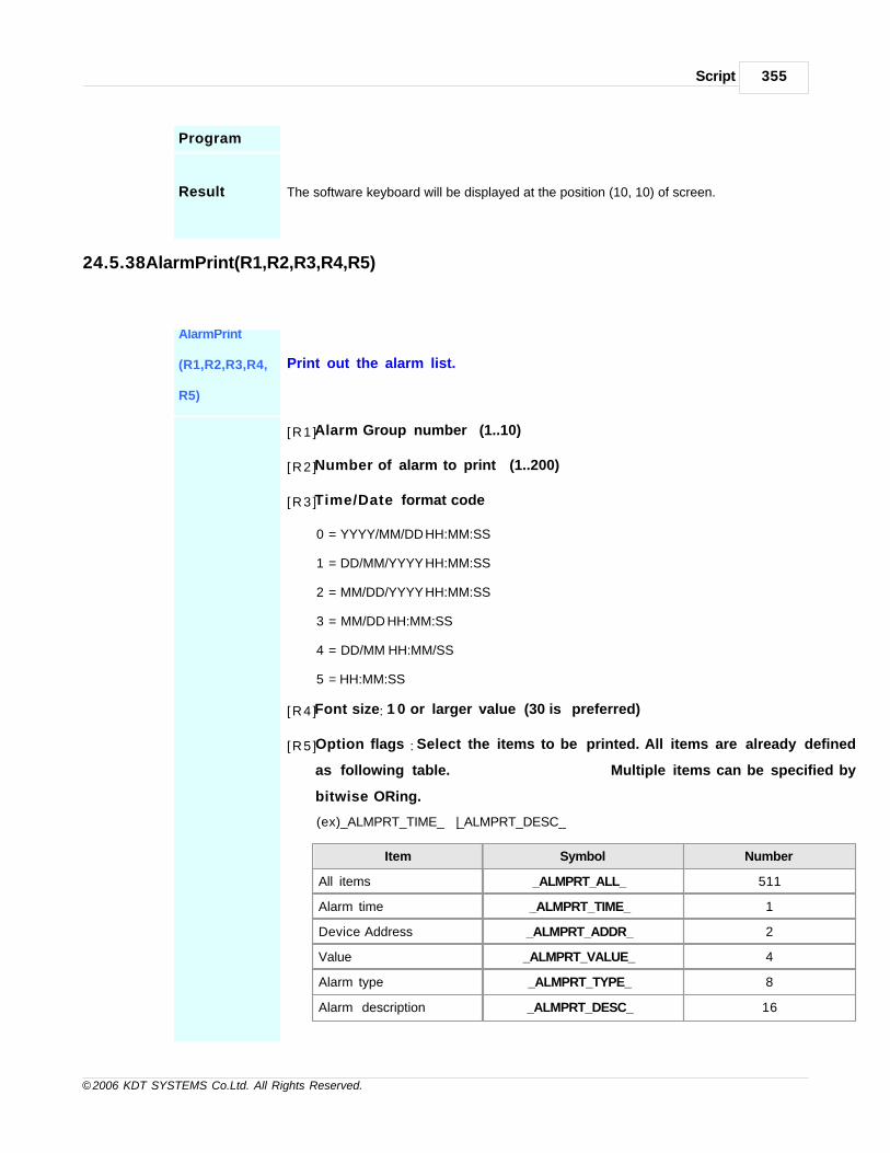
Script 355
© 2006 KDT SYSTEMS Co.Ltd. All Rights Reserved.
Program
Result The software keyboard will be displayed at the position (10, 10) of screen.
24.5.38AlarmPrint(R1,R2,R3,R4,R5)
AlarmPrint
(R1,R2,R3,R4,
R5)
Print out the alarm list.
[R1 ] Alarm Group number (1..10)
[R2 ] Number of alarm to print (1..200)
[R3 ] Time/Date format code
0 = YYYY/MM/DD HH:MM:SS
1 = DD/MM/YYYY HH:MM:SS
2 = MM/DD/YYYY HH:MM:SS
3 = MM/DD HH:MM:SS
4 = DD/MM HH:MM/SS
5 = HH:MM:SS
[R4 ] Font size: 1 0 or larger value (30 is preferred)
[R5 ] Option flags : Select the items to be printed. All items are already defined
as following table. Multiple items can be specified by
bitwise ORing.
(ex) _ALMPRT_TIME_ | _ALMPRT_DESC_
Item Symbol Number
All items _ALMPRT_ALL_ 511
Alarm time _ALMPRT_TIME_ 1
Device Address _ALMPRT_ADDR_ 2
Value _ALMPRT_VALUE_ 4
Alarm type _ALMPRT_TYPE_ 8
Alarm description _ALMPRT_DESC_ 16

CIMON-Xpanel356
© 2006 KDT SYSTEMS Co.Ltd. All Rights Reserved.
Example
ProgramAlarmPrint(1, 10, 1, 10, _ALMPRT_ALL_);
Result At the moment when this function was called, the most recent 10 alarm data of group 1 will be
printed
with font size 10 and “DD/MM/YYYY HH:MM:SS” format.
24.5.39AlarmCsvWr(R1,S2,R3,R4,R5)
AlarmCsvWr
(R1,S2,R3,R4,
R5)
Create a CSV formatted file with the designated alarm group data.
[R1 ] Alarm group number (1..10)
[R2 ] CSV file name (without extension and path)
[R3 ] Time/Date format code
0 = YYYY/MM/DD HH:MM:SS
1 = DD/MM/YYYY HH:MM:SS
2 = MM/DD/YYYY HH:MM:SS
3 = MM/DD HH:MM:SS
4 = DD/MM HH:MM/SS
5 = HH:MM:SS
[R4 ] Option flags : Select the items to be written in CSV file.
All item flags are already defined as following table. Multiple items can be
specified by bitwise ORing.
ex) _ALMPRT_TIME_ | _ALMPRT_DESC_
Item Symbol Number
All items _ALMPRT_ALL_ 511
Time and date _ALMPRT_TIME_ 1
Memory Address _ALMPRT_ADDR_ 2
Value _ALMPRT_VALUE_ 4
Alarm type _ALMPRT_TYPE_ 8

Script 357
© 2006 KDT SYSTEMS Co.Ltd. All Rights Reserved.
Alarm description _ALMPRT_DESC_ 16
[R5 ] CSV file location code (0 : local, 1 : SD/MMC, 2 : USB)
This function creates a CSV formatted file with the designated group of alarm data.
The group number is identified by the first parameter R1.
The second parameter S2 is a name of CSV file to create. There is no need to specify the
extension. But, the path of the CSV file location must be root folder of each storage media
designated by R3 parameter. If there is a file with same name and extension, it will be replaced
with the newly created CSV file without any warning or notification.
The third parameter R3 indicates the storage media where the CSV file will be created. It can
be one of three numbers, 0 to 2. XPanel provides predefined constants for them.
That is, following constant symbols can be used as parameter R3 instead of number.
Media Number Symbol CSV file location
Internal Flash Disk 0 _LOCAL_ \ \ X P a n e l \
SD/MMC 1 _SDMEM_ Root
USB 2 _USBMEM_ Root
Example
ProgramAlarmCsvWr(1, “AlmGrp1”, 0, _ALMPRT_ALL_, _SDMEM_);
Result
Create/Replace a CSV formatted file named as “AlmGrp1.CSV” in SD/MMC memory card with the
group 1 alarm data. All alarm information is written to the output file with the time format of
“YYYY/MM/DD HH:MM:SS”.
24.5.40TouchCalib()
TouchCalib() Opens the touch panel calibration window.
This function opens touch panel calibration window. Follow the instruction displayed in
this window.

CIMON-Xpanel358
© 2006 KDT SYSTEMS Co.Ltd. All Rights Reserved.
Example
ProgramTouchCalib();
ResultAfter completion of touch panel calibration, the system should be shutdown.
Otherwise, the calibration parameters will be lost at next power on.
24.5.41ClearAlarmLog(R1)
ClearAlarmLog
(R1)Clear all messages listed in the designated alarm group (summary)
[R1 ] Alarm group number (1 .. 10)
Example
ProgramClearAlarmLog(1);
Result Clear all alarm messages in the alarm group #1 and summary window.
24.5.42AddMessage(R1, S2)
AddMessage Add a new string to the scroll message window.
Script 359
© 2006 KDT SYSTEMS Co.Ltd. All Rights Reserved.
(R1, S2)
[R1 ] String ID (valid range : 0 .. 9999)
[ S 2 ] The string to add.
Example
Program AddMessage(123, “this message will be scrolled in the bottom window”) ;
Result The given message (S2) string will be scrolled in the scroll message window.
24.5.43RemoveMessage(R1)
RemoveMessa
ge(R1)
Remove a string which was already registered to the scroll message
window by AddMessage() function.
[R1 ] String ID (valid range : 0 .. 9999) which was designated at AddMessage()
function call or -1
(clear all messages in scroll window).
Example
Program RemoveMessage(123);
Result
The message of which ID is 123 will be removed from the scroll message
window.
24.5.44RcpGetSysMem(S1, R2)
RcpGetSysMe
m
(S1, R2)
Copy/move a block of system memory to the recipe group data.

CIMON-Xpanel360
© 2006 KDT SYSTEMS Co.Ltd. All Rights Reserved.
[S1] Recipe model name
[R2 ] System memory address
This function fills the recipe group data with the block data designated by thesystem memory address R2.
Example
Program RcpGetSysMem(“ModelName”, 100);
Result
The recipe group data in memory will be filled with the data block located in the
system memory address 100.
The number of data is determined by the recipe model configuration
24.5.45RcpSetSysMem(S1, R2)
RcpSetSysMe
m
(S1, R2)
Copy/move the recipe group data to the system memory..
[S1] Recipe model name
[R2 ] System memory address
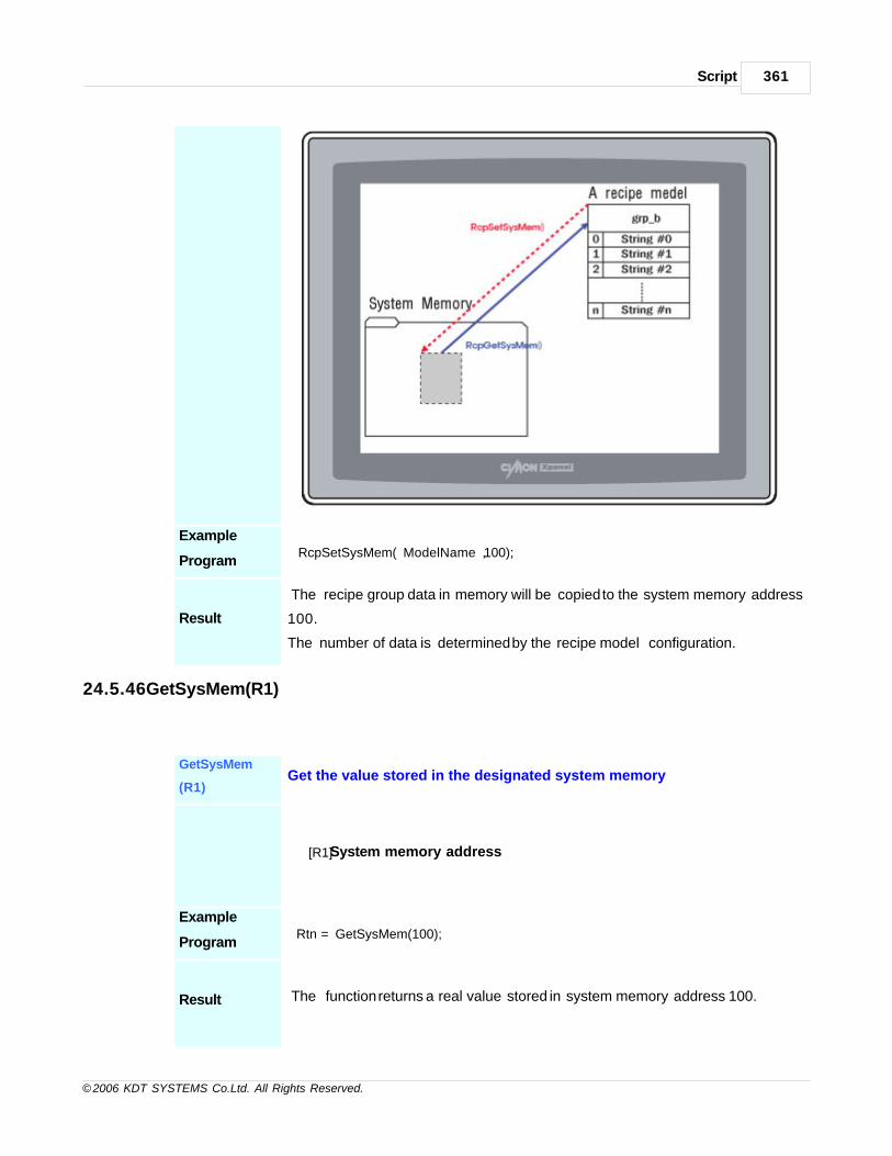
Script 361
© 2006 KDT SYSTEMS Co.Ltd. All Rights Reserved.
Example
Program RcpSetSysMem(“ModelName”, 100);
Result
The recipe group data in memory will be copied to the system memory address
100.
The number of data is determined by the recipe model configuration.
24.5.46GetSysMem(R1)
GetSysMem
(R1)Get the value stored in the designated system memory
[R1] System memory address
Example
Program Rtn = GetSysMem(100);
Result The function returns a real value stored in system memory address 100.

CIMON-Xpanel362
© 2006 KDT SYSTEMS Co.Ltd. All Rights Reserved.
24.5.47SysMemMove (R1)
SysMemMove
(R1)
Move/copy a block of data to the other location within the system
memory.
[R1] System memory address (source)
[R2 ] System memory address (destination)
[R3 ] Number of data
This function copies R3 data from address R1 to R2. If some regions of thesource area and the destinationoverlap, this function ensures that the original source bytes in the overlappingregion are copied before being overwritten.
Example
Program SysMemMove(100,200,10);
Result 10 data (address 100 109) are copied to the memory block of address 200 209.

Script 363
© 2006 KDT SYSTEMS Co.Ltd. All Rights Reserved.
24.5.48SysMemFill(R1,R2,R3)
SysMemFill(R1,
R2,R3)Fill a block of system memory with a specified value.
[R1] System memory address
[R2 ] Fill value
[R3 ] Number of data
This function fills the system memory block started from R1 and size of R3 withthe value of R2.
Example
Program SysMemFill(100, 1234, 10);
Result 10 system memory (address 100 109) are set with a value of ‘1234’.
24.5.49LcdBrightUp()
LcdBrightUp() Lightening the LCD display
XPanel has total 32 steps of LCD brightness. This function increases one step of LCD
brightness from current level.
I f current level is the highest level, this function has no effect.
Example
Program LcdBrightUp();
Result Increase a step of LCD brightness.
24.5.50LcdBrightDown()
LcdBrightDow
n()Darkening the LCD display

CIMON-Xpanel364
© 2006 KDT SYSTEMS Co.Ltd. All Rights Reserved.
XPanel has total 32 steps of LCD brightness. This function decreases one step of LCD
brightness from current level.
I f current level is the lowest level, this function has no effect.
Example
Program LcdBrightDown();
Result Decrease a step of LCD brightness.
24.5.51LcdBacklight(R1)
LcdBacklight
(R1)Turn on / off the LCD backlight
[R1]
Non zero value à Turn the LCD backlight on,
Zero à Turn the LCD backlight off.
This function controls the backlight of LCD.
Any non-zero value of R1 turns on the backlight, and zero turns off the backlight.
Example
Program LcdBacklight(0);
Result Turn the LCD backlight off.
24.5.52StaticBeepCtrl(R1)
StaticBeepCtrl(R1)
Turn on or turn off beep on Xpanel.
[R1]
Beep on / off value (0: Off, 1: On)
This function turn on or turn off beep on Xpanel.
Example
ProgramStaticBeepCtrl(1);
Result It is turn on beep.
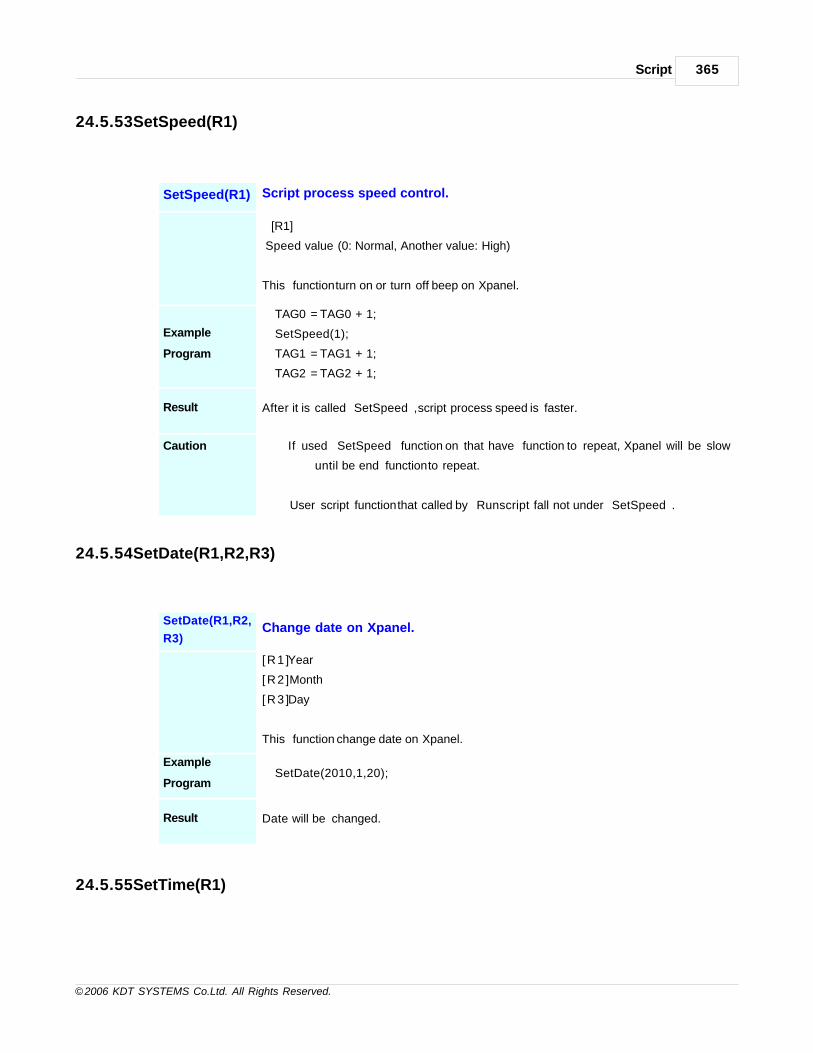
Script 365
© 2006 KDT SYSTEMS Co.Ltd. All Rights Reserved.
24.5.53SetSpeed(R1)
SetSpeed(R1) Script process speed control.
[R1]
Speed value (0: Normal, Another value: High)
This function turn on or turn off beep on Xpanel.
Example
Program
TAG0 = TAG0 + 1;
SetSpeed(1);
TAG1 = TAG1 + 1;
TAG2 = TAG2 + 1;
Result After it is called “SetSpeed”, script process speed is faster.
Caution If used “SetSpeed” function on that have function to repeat, Xpanel will be slow
until be end function to repeat.
User script function that called by “Runscript” fall not under “SetSpeed”.
24.5.54SetDate(R1,R2,R3)
SetDate(R1,R2,
R3)Change date on Xpanel.
[R1 ] Year
[R2 ] Month
[R3 ] Day
This function change date on Xpanel.
Example
ProgramSetDate(2010,1,20);
Result Date will be changed.
24.5.55SetTime(R1)

CIMON-Xpanel366
© 2006 KDT SYSTEMS Co.Ltd. All Rights Reserved.
SetTime(R1) Change time on Xpanel
[ [ R 1 ] Hour
[R2 ] Minute
[R3 ] Second
This function change time on Xpanel.
Example
ProgramSetTime(13,10,0);
Result Date will be changed.

Top Level IntroThis page is printed before anew top-level chapter starts
Part
XXV

CIMON-Xpanel368
© 2006 KDT SYSTEMS Co.Ltd. All Rights Reserved.
25 Scroll Message
Scroll Message is very useful when you want to display alarm or important message emphatically.
If you use scroll message, it will create small window at bottom of the screen for the scroll message.
It will let you reminding the electric signboard or TV caption.
You can configure the scroll message window size, character size, scroll direction, speed and gap between
message as you want.
Applied message at the scroll message will be repeated until it removed. The maximum number of scroll message
is 100 that can be registered.
See :
· Scroll Message Configuration
· Apply Scroll Message

Scroll Message 369
© 2006 KDT SYSTEMS Co.Ltd. All Rights Reserved.
25.1 Scroll Message Configuration
Scroll Message Configuration
[Tools] -> [CIMON-XPANEL Setup(X)] -> [Using Scroll Message] -> [Scroll Message]
Configuration Items

CIMON-Xpanel370
© 2006 KDT SYSTEMS Co.Ltd. All Rights Reserved.
Scroll Message
Height
Scroll Message is created from the bottom of the screen.
So scroll message height must be shorter than screen height.
Text Size Configure text size of scroll message. Text size must smaller than scroll message
height
Scroll Message
Gap
It configures distance between messages.
Scroll Message
Speed
It configures message scrolling speed.
Text Color, Back
Color
It configures text color and background color.
Scroll Direction It configures the scrolled direction.
25.2 Apply Scroll Message
Apply from alarms
[Tools] -> [Alarms] -> [Add],[Edit] -> [Apply Scroll Message]

Scroll Message 371
© 2006 KDT SYSTEMS Co.Ltd. All Rights Reserved.
Message index at alarms
When scroll messages are applied from alarms, each message is allowed index automatically.
Please reference scroll message index generated automatically from the alarms as the following.
Alarm Group Index number
Group 1 10000 - 10063
Group 2 10100 - 10163
Group 3 10200 - 10263
Group 4 10300 - 10363
Group 5 10400 - 10463
Group 6 10500 - 10563
Group 7 10600 - 10663
Group 8 10700 - 10763
Group 9 10800 - 10863
Group 10 10900 - 10963
Apply scroll message using script

CIMON-Xpanel372
© 2006 KDT SYSTEMS Co.Ltd. All Rights Reserved.
You can apply scroll message by using script function.
When you add scroll messages, you must attend the scroll message index. If it is duplicated, it will not be
added.
Ad
d
me
ss
ag
e
AddMessage(R1, S2)
[R1] Appling Index(0-9999) [S2] Appling Message
Example ) AddMessage(1, "Warning")
Re
mo
ve
Me
ss
ag
e
RemoveMessage(R1)
[R1] Removing Index(0-9999, If you use number-1, then it will remove all items)
Example ) RemoveMessabe(1);
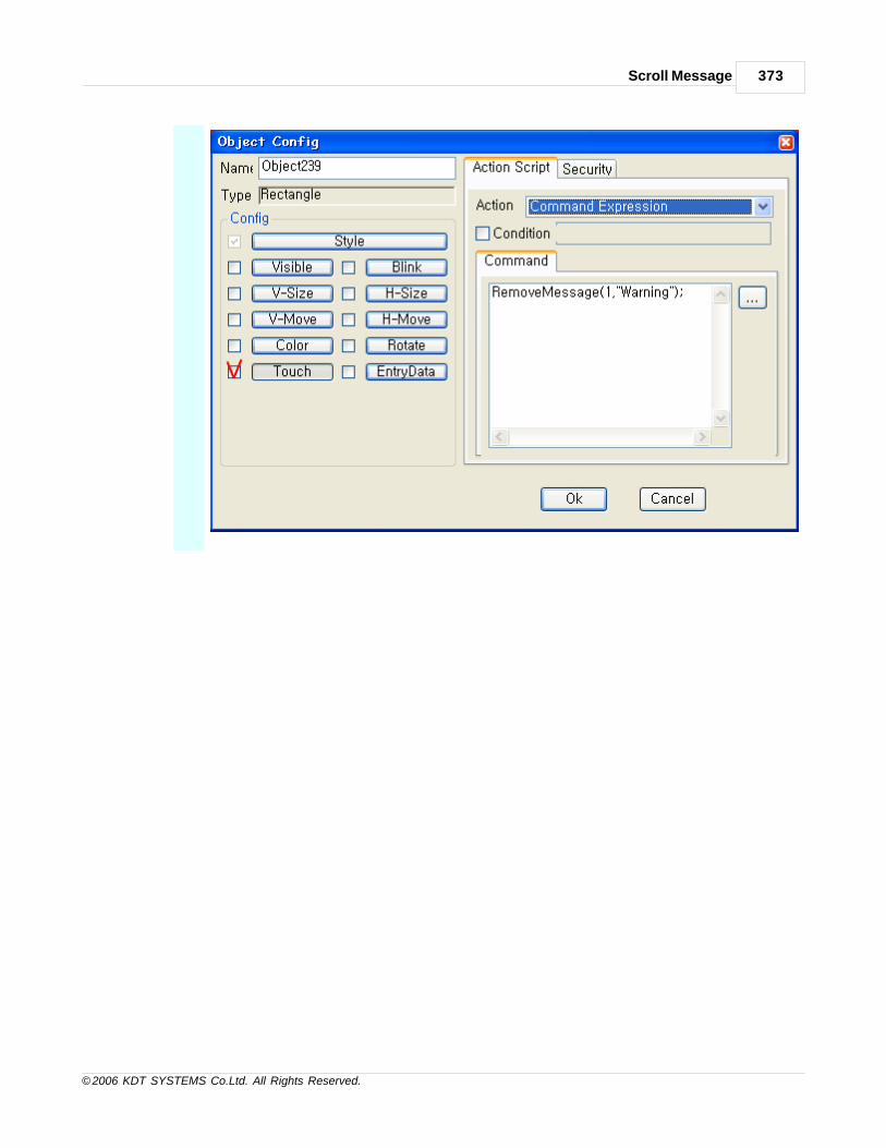
Scroll Message 373
© 2006 KDT SYSTEMS Co.Ltd. All Rights Reserved.

Top Level IntroThis page is printed before anew top-level chapter starts
Part
XXVI

Indirect Address 375
© 2006 KDT SYSTEMS Co.Ltd. All Rights Reserved.
26 Indirect Address
Indirect Tag
The indirect tag is to describe one tag by two tags that are divided into Target tag and Offset tag.
As described by the indirect tag, the address of Target tag is handled to change, referring to the tag’s value
designated as Offset tag.
For example, if the tag’s value designated as Offset tag is 0, it will be same value with the designated
address of tag designated as Target tag
Also, if the value of Target tag is 2, it will express the value that is 2 plus the address designated to Target
tag.
Notation Method
Write - “#” between Target Tag and Offset Tag
Ex) Target_Tag#Offset_Tag
Attention
Offset tag is that all analogue tag and digital tag with sate value(in case of I/O device, there are some tags
without sate value) are registered,
but Target tag is specified only real tag with the I/O device below.
In case of using the tag with I/O device that is not described on the bottom is managed as normal tag.
Supporting Indirect Tag Device
KDT SYSTEMS CIMON-PLC
KDT SYSTEMS CIMON-PLC HMI
KDT SYSTEMS CIMON-PLC Loader
KDT SYSTEMS XPANEL
Allen Bradley DF1
DELTA TAU PMAC Drive
FUJI Micrex SX
KEYENCE PLC (KV mode)
KOYO DirectNet
LSIS GLOFA PLC Cnet
LSIS GLOFA PLC Enet

CIMON-Xpanel376
© 2006 KDT SYSTEMS Co.Ltd. All Rights Reserved.
LSIS Master-K S-Series Enet
LSIS Master-K H Series PLC Cnet
LSIS Master-K S Series PLC Cnet
LSIS Master-K S Series PLC Loader
LSIS XGT/XGB Series PLC Cnet
LSIS XGT Series FEnet
MITSUBISHI MELSEC A Loader
MITSUBISHI MELSEC 1C (AnA/Anu CPU)
MITSUBISHI MELSEC 1C (A CPU)
MITSUBISHI MELSEC FX
MITSUBISHI MELSEC 1E
MITSUBISHI MELSEC 3E
MITSUBISHI MELSEC 3E (ASCII)
MITSUBISHI MELSEC FX Loader
MITSUBISHI MELSEC-Q Loader (Q00/01)
MITSUBISHI MELSEC-Q Loader (Q02/06/12/25)
YASKAWA MEMOBUS RTU
MODBUS ASCII protocl
MODBUS RTU protocl
MODBUS TCP
MAIS FPO MEWTOCOL-COM
OMRON PLC (Host Link)
SIEMENS RK512/3964R
SIEMENS S7 Ethernet
SIEMENS S7 MPI
SIEMENSE S7 PPI Direct
SAIA S-BUS
YOKOGAWA Computer Link Protocol
It is ignored when the value of Offset tag is under 0, and numbers under a decimal point are thrown.
26.1 Using Indirect Tag
Indirect Tag can be used by following functions.
Supporting Functions of Indirect Tag
Tag Value, Key Input Window, String Value, Animation bitmap, Visible, Blink, V-Size, H-Size, V-Move, H-
Move, Color, Rotate, Touch, Entry Data, Command, Script.
Example for Indirect Tag

Indirect Address 377
© 2006 KDT SYSTEMS Co.Ltd. All Rights Reserved.
Register - I/O device to support the Indirect Tag
Refer to the Indirect Device Item described ahead. "KDT SYSTEMS CIMON-PLC HMI" is used here.
Register - Target Tag and Offset Tag to Database
ANA_01 -> Target Tag

CIMON-Xpanel378
© 2006 KDT SYSTEMS Co.Ltd. All Rights Reserved.
ANA_00 -> Offset Tag
Open a Page and Select a Tag Value Object. Register "Object Configuration" as follows.
Display - The value of Offset Tag

Indirect Address 379
© 2006 KDT SYSTEMS Co.Ltd. All Rights Reserved.
Display - The basic area value of Target Tag
Display - The value of Indirect Tag
The value of other areas is displayed by the value of Offset Tag(ANA_00).
Make - Buttons to change the value of "Offset Tag" and "Indirect Tag"

CIMON-Xpanel380
© 2006 KDT SYSTEMS Co.Ltd. All Rights Reserved.
Input commands as like follows at ‘+’ button property of Offset change.
ANA_00 = ANA_00 + 1;// When touching, the value of Offset Tag will automatically increases by 1.
Input commands as like follows at ‘- ’ button property of Offset change.
if(ANA_00 > 1) // If the value is larger than 1,
ANA_00 = ANA_00 - 1; // When touching, the value of Offset Tag will automatically decreases by 1.
Input commands as like follows at ‘+’ button property of Data change.
ANA_01#ANA_00 = ANA_01#ANA_00 + 1; // When touching, the value of Indirect Tag will automatically
increases by 1.
Input commands as like follows at ‘- ’ button property of Data change.
ANA_01#ANA_00 = ANA_01#ANA_00 - 1; // When touching, the value of Indirect Tag will
automatically decreases by 1.
Download the project and check the changing value while touching button.

Top Level IntroThis page is printed before anew top-level chapter starts
Part
XXVII

CIMON-Xpanel382
© 2006 KDT SYSTEMS Co.Ltd. All Rights Reserved.
27 Communication Driver
Company Driver
ASI Controls ASIC Protocol
Barcode Scanner Barcode Scanner
Danfoss Danfoss VLT Automation Drive FC300
DELTA TAU DELTA TAU PMAC
HITACHI HITACHI Inverter SJ300/L300P
KDT SYSTEMS KDT SYSTEMS CIMON-PLC HMI (RS232C/RS422A)
KDT SYSTEMS CIMON-PLC Loader (RS232C/RS422A)
KDT Systems Xpanel Master
Keyence Keyence KV Mode
KOYO KOYO DirectNet
LSIS LSIS GLOFA Cnet
LSIS GLOFA Enet
LSIS GLOFA Loader
LSIS XGT Cnet
LSIS XGT Enet
LSIS Master-K S Series PLC Loader
LSIS Master-K S Series PLC Cnet
LSIS Master-K H Series PLC Cnet
LSIS Master-K S Series PLC Enet
LSIS Inverter Starvert
MITSUBISHI MITSUBISHI Inverter FR-E500
MITSUBISHI Melsec 1C (ACPU, AnA/AnU CPU)
MITSUBISHI Melsec 3E(Q/QnA)
MITSUBISHI Melsec 1E
MITSUBISHI Melsec 3E ASCII
MITSUBISHI Melsec A Series (Programming Port)
MITSUBISHI Melsec FX Series
MITSUBISHI Melsec FX Series (Programming Port)
MITSUBISHI Melsec Q Series (Programming Port)
MITSUBISHI Melsec FX2N-10/20GM(Programming Port)
MODBUS Protocol MODBUS RTU protocl
MODBUS TCP protocl
NAIS NAIS PLC FP Series (MEWTOCOL-COM)

Communication Driver 383
© 2006 KDT SYSTEMS Co.Ltd. All Rights Reserved.
OMRON OMRON HostLink
FINS Ethernet
SAIA SAIA S-BUS
SIEMENS SIEMENS RK512/3964R
SIEMENS S7 Ethernet
SIEMENS S7 MPI
SEIMENS S7 PPI Direct
ALLENBRADLEY ALLENBRADLEY DF1
YOKOGAWA YOKOGAWA Personal Computer Link
Fuji Fuji Micrex SX Ethernet
METRONIX APD METRONIX APD
FARA N70/700 PLUS FARA N70/700 PLUS
Samsung BRAIN SPC Series Samsung BRAIN SPC Series
27.1 ASIC Protocol
This driver supports the ASI communication protocol of ASI Controls.
This protocol provides communication access to a network of ASI controllers from Xpanel.
Communication Setup : Xpanel
Create a newdevice For creating a new device activate the menu ‘Tools’- >’I/O Devices’ or icon in tool-bar.
Following picture shows the first step of creating a new device.
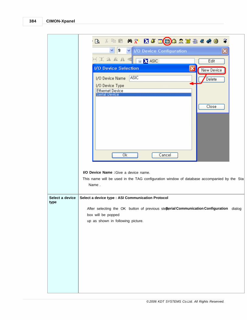
CIMON-Xpanel384
© 2006 KDT SYSTEMS Co.Ltd. All Rights Reserved.
I/O Device Name : Give a device name.
This name will be used in the TAG configuration window of database accompanied by the ‘Station
Name’.
Select a devicetype
Select a device type : ASI Communication Protocol
After selecting the ‘OK’ button of previous step, ‘Serial Communication Configuration’ dialog
box will be popped
up as shown in following picture.
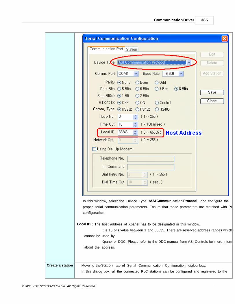
Communication Driver 385
© 2006 KDT SYSTEMS Co.Ltd. All Rights Reserved.
In this window, select the ‘Device Type’ as ‘ASI Communication Protocol’ and configure the
proper serial communication parameters. Ensure that those parameters are matched with PLC
configuration.
Local ID : The host address of Xpanel has to be designated in this window.
It is 16 bits value between 1 and 65535. There are reserved address ranges which
cannot be used by
Xpanel or DDC. Please refer to the DDC manual from ASI Controls for more information
about the address.
Create a station Move to the ‘Station’ tab of ‘Serial Communication Configuration’ dialog box.
In this dialog box, all the connected PLC stations can be configured and registered to the

CIMON-Xpanel386
© 2006 KDT SYSTEMS Co.Ltd. All Rights Reserved.
Xpanel.
Each field can be configured with following rules.
Station Name Give a name to the PLC.
This name will be used in the database window accompanied with the
‘Device Name’.
Station Type Choose the type of connected PLC among the “ASIC”.
Network ID This field has no effect
Station No. Specify a decimal number between 1 and 65535.
This number must be matched with the node address of the DDC.
16Bit Data
Swap
This option swaps bytes of all word or double word sized data.
Following diagram shows an example of byte swapping.

Communication Driver 387
© 2006 KDT SYSTEMS Co.Ltd. All Rights Reserved.
Almost all of the data type will be influenced by this option except
INT8 / UINT8 / BCD8 / UBCD8.
32Bit Data
Swap
This option swaps words of all double word sized data.
Following diagram shows an example of word swapping.
INT32 / UINT32 / BCD32 / UBCD32 / FLOAT type of TAG values will be
influenced by
this option.
Using
CheckSum
This field has no effect.
This communication driver always checks the check-sum.
Comm.Error
Message Pop
Up
If this item is checked, Xpanel displays a communication error notification
message at every Rx and Tx error. Otherwise(unchecked), Xpanel does not
display the message at data receive error. Only when there is data transmit
(writing a TAG value to the station) error, the notification message is popped
up. This message box will be closed automatically about 5 seconds after.
Data Address
Xpanel supports reading object and table data from DDC. These two data can be referenced by following
TAG address format.
[Object] O[ Obj No ].[ Size ].[ Index ].[ Attribute ](:Bit No) [Table] T[ Table No ].[ Offset ](:Bit No)
Obj No / Table No
Designate the object (table) number of data location.
Please refer to the object definition of connected DDC, for more information about
object.
Size Designate the data type. It can be 1 (BYTE) or 2 (WORD).
Offset Designate the byte offset within the table.
Index Designate the assigned index number within the given object.
Attribute Designate the attribute number of data.
:Bit No Designate the bit number. This bit address notation is used in digital TAG. Notice

CIMON-Xpanel388
© 2006 KDT SYSTEMS Co.Ltd. All Rights Reserved.
that the TAG with this bit number only can be read.
That is, the digital TAG writing is not supported with ASIC protocol driver.
Bit number has to be within the range of data size. In case of a table (T) or object
(O) with size 1 (BYTE), bit number can be between 0 and 7. Elsewhere, object with
size 2 (WORD), bit number can be between 0 and 15.
AddressExamples
O33.2.0.0 Object 33, WORD, Index 0, Attribute 0
T10.0 Table 10, Byte offset 0
O32.1.0.8 Object 32, BYTE, Index 0, Attribute 8
O3.2.11.0:0 Object 3, WORD, Index 11, Attribute 0, Bit 0
TAG Data Type ASIC DDC supports two types of data, BYTE and WORD. If the data type of TAG was
larger than that, Xpanel will read next continuously positioned data for making
designated data. For example, if UINT32 type of TAG referred to the address of T1.2,
Xpanel will read T1.2, T1.3, T1.4 and T1.5 for assembling the UINT32 data.
Wiring Diagram
RS232C

Communication Driver 389
© 2006 KDT SYSTEMS Co.Ltd. All Rights Reserved.
RS422/485
27.2 Barcode Scanner
This driver provides the function of communication with the barcode scanner via RS232C.
The barcode scanner driver is distinct from other standard drivers. It does not support real TAG.
This driver receives the characters from barcode scanner and converts them to keyboard input.
Because of that, in Xpanel kernel’s point of view, the barcode scanner is just like as a standard
keyboard.
To utilize the data from the barcode scanner, the ‘keyboard input window’ object must be used in the
graphic page design.
This topic is described in this manual.
Communication Setup : Barcode Scanner
Follow the manual from barcode scanner vender.
Make the confirmation of following condition during barcode scanner setup.
· ‘Enter (0Dh)’ or other special code must be added at the end of data transmission.
· Prepare the communication parameters from vender’s documentation. (Baudrate, Parity, Stop Bit,
Data Bits, Stop Bit)
Communication Setup : Xpanel
Create a newdevice For creating a new device, use the menu ‘Tools’- >’I/O Devices’ or icon in tool-bar.
Following picture shows the first step of creating a new device.
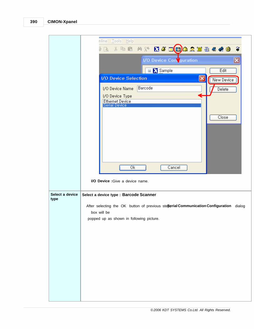
CIMON-Xpanel390
© 2006 KDT SYSTEMS Co.Ltd. All Rights Reserved.
I/O Device : Give a device name.
Select a devicetype
Select a device type : ‘Barcode Scanner’
After selecting the ‘OK’ button of previous step, ‘Serial Communication Configuration’ dialog
box will be
popped up as shown in following picture.

Communication Driver 391
© 2006 KDT SYSTEMS Co.Ltd. All Rights Reserved.
Device Tpe Barcode Scanner
Comm. Port COM1
Baud Rate 9,600 bps
Parity None
Data Bits 8 Bits
Stop Bit(s) 1 Bit
RTS/CST OFF
Comm.Type RS-232
Retry No. 3
Time Out 30

CIMON-Xpanel392
© 2006 KDT SYSTEMS Co.Ltd. All Rights Reserved.
Create a station Move to the ‘Station’ tab of ‘Serial Communication Configuration’ dialog box.
In this dialog box, all the connected PLC stations can be configured and registered to the
XPanel.
Each field can be configured with following rules.
Station Name Give a name to the barcode scanner.)
Station Type Choose the ‘BarCode’. (No other type can be selected.)
Network ID his field has no effect.
Station No. 0
16Bits Data
Swap
his field has no effect.
32Bits Data his field has no effect.

Communication Driver 393
© 2006 KDT SYSTEMS Co.Ltd. All Rights Reserved.
Swap
'Key Input Window' Object : Xpanel (Page Designer)
‘Key input window’ object displays the input character to the screen and executes the assigned
commands when the predefined terminating code
input is detected.
End Code
(HEXA)
This field must be matched with terminating code of the barcode scanner.
Typically 0Dh (Enter) code is widely used.
Input Tag Name This field must be designated a string TAG.
The input string from barcode scanner is stored in this string TAG.
Command On
Input
Describe the command script in this field.
When the ‘End Code’ is received, this command script is executed automatically.
Password Type This option can be used when there is need to hide input characters.
If this option was checked, the input characters will be seen as ‘*’ character.

CIMON-Xpanel394
© 2006 KDT SYSTEMS Co.Ltd. All Rights Reserved.
Clear at End
Code
If this option was checked, the string on screen will be cleared when ‘End Code’
is received. Otherwise, the string on screen will be cleared when there is a new
input.
Communication Cable Wiring
RS232C
Above picture shows only the RS232C port of Xpanel. This is the standard DB9 RS232C pin assignment.
Typically RD and SG pins are enough to communicate with general barcode scanner. Refer to the manual
of your barcode scanner for signal description.
27.3 Danfoss VLT Automation Drive FC300
This driver can communicate with the VLT AutomationDrive FC 300 inverter series from Danfoss.
Communication Setup : Inverter Setting(FC300, VLT2800)
InverterSetting(FC300)
For normal communication, following parameters of the inverter must be set as stated.
· Parameter 8-10 : FC profile [0]
· Parameter 8-30 : FC MC [1]
Parameter Number Set Value Description
8-311 [1] Station number 1. (any number between 1 to 126)
8-321 [3] 19200 bps
8-351 [10] 10 ms Min. response delay

Communication Driver 395
© 2006 KDT SYSTEMS Co.Ltd. All Rights Reserved.
8-361 [5000] 5000 ms Max. response delay
8-371 [25] 25 ms Max. inter-char delay
8-102 [ 0 ] FC Profile
8-302 [ 1 ] FC MC
(Note 1) Those parameters (8-31 to 8-32) must be matched with the settings of Xpanel.
(Note 2) The parameters of 8-10 and 8-30 must be set as the value shown in this example.
If those parameters were set as other values, Xpanel can not communicate with the inverter.
InverterSetting(VLT2800)
For normal communication, following parameters of the inverter must be set as stated.
· Parameter 512 : FC profile [1]
Parameter Number Set Value Description
5001 [1] Station number. (any number between 1 to 247)
5011 [5] 9600 bps
5022 [ 1 ] FC Profile
(Note 1) Those parameters (500 and 501) must be matched with the settings of Xpanel.
(Note 2) The parameter of 512 must be set as the value shown in above table.
If this parameter was set as other value, Xpanel can not communicate with the inverter.
Communication Setup : Xpanel
Createanewdevice
For creating a new device the menu, 'Tool > I/O Devices' or icon in tool bar.
Following picture shows the first step of creating a new device.

CIMON-Xpanel396
© 2006 KDT SYSTEMS Co.Ltd. All Rights Reserved.
I/O Device Name : Give a device name. This name will be used in the TAG configuration window of
database accompanied by the 'Station Name'.
Selectadevicetype
Device type : ' DANFOSS VLT AutomationDrive FC-300 '
After selecting the ‘OK’ button of previous step, ‘Serial Communication Configuration’ dialog box will
be popped up as shown in following picture.

Communication Driver 397
© 2006 KDT SYSTEMS Co.Ltd. All Rights Reserved.
Note
FC 300 supports the RS485 only with even parity, 8 data bits and 1 stop bit.
In this window, select the ‘Device Type’ as ‘DANFOSS VLT AutomationDrive FC-300’ and configure
the
proper serial communication parameters.
Createastation
Move to the ‘Station’ tab of ‘Serial Communication Configuration’ dialog box.
In this dialog box, all the connected PLC stations can be configured and registered to the Xpanel.
Each field can be configured with following rules.

CIMON-Xpanel398
© 2006 KDT SYSTEMS Co.Ltd. All Rights Reserved.
Station Name Give a name to the PLC.
This name will be used in the database window accompanied with the 'Device Name'.
Station Type Choose the 'FC-300'. (No other type can be selected.)
Network ID This field has no effect.
Station No. Specify a decimal number between 0 and 9.
16Bits Data
Swap
This field has no effect.
32Bits Data
Swap
This field has no effect.
Using Checksum This field has no effect.
Comm. Error
Message pop Up
If this item is checked, Xpanel displays a communication error notification message at
every Rx and Tx error.

Communication Driver 399
© 2006 KDT SYSTEMS Co.Ltd. All Rights Reserved.
Otherwise(unchecked), Xpanel does not display the message at data receive error.
Only when there is data transmit (writing a TAG value to the station) error, the
notification message is popped up. This message box will be closed automatically
about 5 seconds after.
Address Notation
The address of TAG in Xpanel has the following format.
TAG Type Format Example
Analog [Symbol][Decimal Number] P023
Digital [Symbol][Decimal Number][.][Hexadecimal Number] P000.F
Symbol
Address
Description Access
P 0001 -
1760
Parameter Area
The address of each TAG can be induced from the parameter number of
FC 300 or VLT 2800. For example, to monitor the ’16-17 Speed [RPM]’
of FC 300, the address should be designated with ‘P1617’. For more
parameters, please refer to the ‘How to Program’ section of “FC 300
Design Guide”.
The value written to this address will be transferred to the FC 300 or VLT
2800 directly. That means, parameters of the inverter can be modified by
writing a desired value to this address. The new value can be stored in not
only RAM also EEPROM of FC 300. For storing set value to the EEPROM,
C002 point must have a non-zero value.
R/W
C 000 Control Code
1 word sized control data. Each bit has its own control meaning which is
shown in following [control code] table. To control FC 300 or VLT 2800,
write a value of combination of the table.
Ensure that the reference (C001) must be set as desired value before
issuing of this control code.
W
001 Reference
This point is a signed word data (-32767 - +32767), and the range of data
corresponds to -200% to +200% of reference. For example, the value of

CIMON-Xpanel400
© 2006 KDT SYSTEMS Co.Ltd. All Rights Reserved.
16384 represents 100% of reference.
This reference value must be set before the actual control by control code
(C000).
002 EEPROM Writing
If this is non-zero, the value written to the parameter area (Pnnnn) will
be saved to the EEPROM as well as RAM of FC 300 or VLT 2800.
Otherwise, the set value will be stored only in RAM. Ensure that the value
of this point is what you wanted before parameter writing.
Above addresses can be used in both of analog and digital TAG.
For more information of each point, please refer to the ‘FC 300 Design Guide’.
[C000 : Control Code for FC300]
Bit No. Bit Value = 0 Bit Value = 1
00 Reference value External selection lsb
01 Reference value External selection msb
02 DC brake Ramp
03 Coasting No coasting
04 Quick stop Ramp
05 Freeze output Use ramp
06 Ramp stop Start
07 No function Reset
08 No function Jog
09 Ramp 1 Ramp 2
10 Data not valid Data valid
11 Relay 01 open Relay 01 active
12 Relay 02 open Relay 02 active
13 Parameter set-up Selection lsb
14 Parameter set-up Selection msb
15 No function Reverse
[ Note ] For more information of each bit, refer to the ‘Control Word According to FC Profile (CTW)’
section of ‘FC 300 Design Guide’.
[C000 : Control Code for VLT2800]
Bit No. Bit Value = 0 Bit Value = 1
00 Preset ref. lsb
01 Preset ref. msb

Communication Driver 401
© 2006 KDT SYSTEMS Co.Ltd. All Rights Reserved.
02 DC brake
03 Coasting stop
04 Quick stop
05 Freeze output freq.
06 Ramp stop Start
07 Reset
08 Jog
09 Ramp 1 Ramp 2
10 Data not valid Data valid
11 Relay 01 activated
12 Digital output terminal 46 activated
13 Selection Setup, lsb
14 Selection Setup, msb
15 Reverse
[ Note ] For more information of each bit, refer to the 'Control Word According to FC Profile(CTW)'
section of 'FC 2800 Design Guide'.
[Example : Monitors the frequency data]
1. Make an analog TAG for frequency data. The address can be induced from parameter number 16-13.
Designate ‘P1613’ as the address of new analog TAG.
2. Setup the scale factor of the analog TAG if needed. ‘Conversion index’ of parameter 16-13 is -1.
Configure the scaling factor of the TAG in database as 0.1. (The ‘Conversion index’ and other useful
information of each parameter
can be found on the ‘Parameter Lists’ section of the ‘FC 300 Design Guide’.)

CIMON-Xpanel402
© 2006 KDT SYSTEMS Co.Ltd. All Rights Reserved.
[Example : Changes the 'speed PID lowpass filter time']
1. Make two analog TAGs. One TAG is for EEPROM storage control and the other TAG is for the parameter.
The address of parameter TAG can be induced from parameter number 7-06. Designate P0706 as the
address of the new analog TAG.

Communication Driver 403
© 2006 KDT SYSTEMS Co.Ltd. All Rights Reserved.
2. Setup the scale factor of the analog TAG. In this example, the value of 0.1 was designated as the scale
factor.
This value came from the ‘Conversion index’ of the parameter 7-06. But the conversion index of par.
7-06 is -4.
This index is based on the unit of second. For convenience, we can use the unit of milli-second, such
that the index can be thought as the value of -1.
3. The parameter of FC 300 can be modified by changing the TAG.
If needed but not necessarily, before the writing a new parameter value, the EEPROM storing option can
be arranged.
Following picture shows an example of changing parameter.
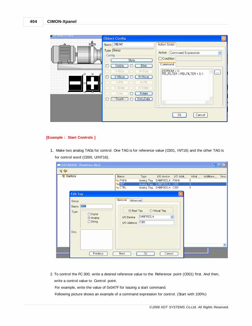
CIMON-Xpanel404
© 2006 KDT SYSTEMS Co.Ltd. All Rights Reserved.
[Example : Start Controls ]
1. Make two analog TAGs for control. One TAG is for reference value (C001, INT16) and the other TAG is
for control word (C000, UINT16).
2. To control the FC 300, write a desired reference value to the ‘Reference’ point (C001) first. And then,
write a control value to ‘Control’ point.
For example, write the value of 0x047F for issuing a start command.
Following picture shows an example of a command expression for control. (Start with 100%)

Communication Driver 405
© 2006 KDT SYSTEMS Co.Ltd. All Rights Reserved.
Communication Cable Wiring

CIMON-Xpanel406
© 2006 KDT SYSTEMS Co.Ltd. All Rights Reserved.
NOTE
(Note 1) Shielded twisted pair cable must be used for P-N pair.
(Note 2) Ensure that shield cable was connected to the COM terminal (61) of FC 300.
27.4 DELTA TAU PMAC
This driver provides the software interface and communication protocol between Xpanel and DELTA TAU
PMAC series drivers.
Communication Setup : PMAC
For normal communication between Xpanel and PMAC, the some of I-variables should have the values
described below.
I -variable
SetValue
Remark
I0 0 .. 15 The station number ‘0’ is the default value of PMAC. To set up the PMAC to
communicate as station 1 to 15 on a multi-drop serial cable, first communicate with
the board as station 0. Set I0 to specify the new station number. Also set I1 to 3 to
enable the station number addressing.

Communication Driver 407
© 2006 KDT SYSTEMS Co.Ltd. All Rights Reserved.
I1 3 CS handshake not used; software card address required.
I3 2 Communication handshake style and code
I4 0 Checksum disabled, serial errors reported immediately
I6 1 Error reporting mode.
I9 0 or 2 0 (short form of decimal) or 2 (short form of hexadecimal)
I63 1 Echo the <Control-X> character
I64 1 Internal response tag enable
Store these values to the non-volatile flash memory with the ‘SAVE’ command. Then turn off power.
Please refer to the manual of PMAC for more information.
Communication Setup : Xpanel
Create a newdevice For creating a new device activate the menu ‘Tools’ -> ’I/O Devices’ or icon in tool-bar.
Following picture shows the first step of creating a new device.

CIMON-Xpanel408
© 2006 KDT SYSTEMS Co.Ltd. All Rights Reserved.
I/O Device Name : Give a device name. This name will be used in the TAG configuration window
of database
accompanied by the ‘Station Name’.
Select a devicetype
Select a device type : ' DELTA TAU PMAC Drive '
After selecting the ‘OK’ button of previous step, ‘Serial Communication Configuration’ dialog
box will be
popped up as shown in following picture..
In this window, select the ‘Device Type’ as ‘DELTA TAU PMAC Drive’ and configure the proper
serial
communication parameters. (9600bps, no parity, 8 data bits, and 1 stop bit recommended)

Communication Driver 409
© 2006 KDT SYSTEMS Co.Ltd. All Rights Reserved.
Create a station Move to the ‘Station’ tab of ‘Serial Communication Configuration’ dialog box.
In this dialog box, all the connected PLC stations can be configured and registered to the Xpanel.
Each field can be configured with following rules.
Station Name Give a name to the PLC.
This name will be used in the database window accompanied with the ‘
Device Name’.
Station Type Choose the ‘PMAC’. (No other type can be selected.)
Network ID This field has no effect.
Station No. Specify a decimal number between 0 and 15.
16bits Data
Swap
This field has no effect.

CIMON-Xpanel410
© 2006 KDT SYSTEMS Co.Ltd. All Rights Reserved.
32bits Data
Swap
This field has no effect.
Using
Checksum
This field has no effect.
Comm. Error
Message pop
Up
If this item is checked, Xpanel displays a communication error notification
message at every Rx and Tx error.
Otherwise(unchecked), Xpanel does not display the message at data receive
error. Only when there is data transmit (writing a TAG value to the station)
error, the notification message is popped up. This message box will be closed
automatically about 5 seconds after.
Address Notation
The address of TAG in Xpanel has the following format.
TAG Type Format Example
Analog [Symbol][Address] P0012
Digital [Symbol][Address] M0215
· Address : decimal number between 0 and 8191
· All the addresses can be used with the digital TAG. The value of zero (0) is treated as OFF and other
values are treated as ON in Xpanel.
Following table shows the list of devices which can be referenced in Xpanel database.
Symbol Description AddressRange
Type Access
I Variable of fixed meaning for card setup 0-8191 Analog R/W
P Global variable for programming use 0-8191 Analog R/W
M Variable assigned to memory location for user 0-8191 Analog R/W
Q Local variable for programming use 0-8191 Analog R/W
DELTA TAU PMAC communication driver supports only FLOAT data type. Ensure that the data
type of TAGs.
(Following picture shows the FLOAT data type configuration window ofXpanell database.)

Communication Driver 411
© 2006 KDT SYSTEMS Co.Ltd. All Rights Reserved.
Communication Cable Wiring
Xpanel COM1/COM2RS232C
Connector Type :D89
Xpanel COM1 RS422A
Connector Type :5 Pins TerminalBlock
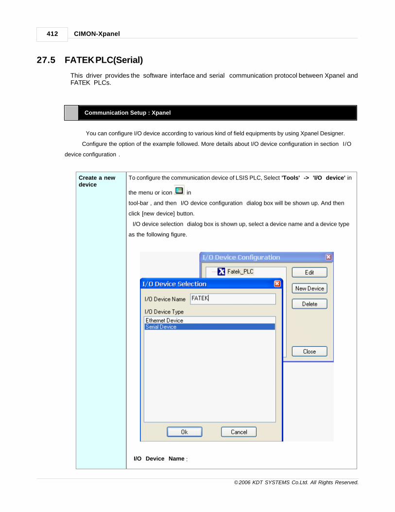
CIMON-Xpanel412
© 2006 KDT SYSTEMS Co.Ltd. All Rights Reserved.
27.5 FATEK PLC(Serial)
This driver provides the software interface and serial communication protocol between Xpanel andFATEK PLCs.
Communication Setup : Xpanel
You can configure I/O device according to various kind of field equipments by using Xpanel Designer.
Configure the option of the example followed. More details about I/O device configuration in section “I/O
device configuration”.
Create a newdevice
To configure the communication device of LSIS PLC, Select 'Tools' -> 'I/O device' in
the menu or icon in
tool-bar , and then “I/O device configuration” dialog box will be shown up. And then
click [new device] button.
“I/O device selection” dialog box is shown up, select a device name and a device type
as the following figure.
I/O Device Name :

Communication Driver 413
© 2006 KDT SYSTEMS Co.Ltd. All Rights Reserved.
Give a device name. This name will be used in the TAG configuration window
of database accompanied
by the ‘Station Name’.
Select a devicetype
Select a device type : ' Fatek PLC Cnet '
After selecting the ‘OK’ button of previous step, ‘Serial CommunicationConfiguration’ dialog box will be popped up as shown in following picture.
In this window, select the ‘Device Type’ as ‘Fatek PLC Cnet’ andappropriate communication parameters. Those parameters must bematched with the PLC.
Create a station Move to [Station] tab at the “Serial Communication Configuration” Dialog Box and click
[Add Station] button then you can see “Station” Dialog Box popped up. Please

CIMON-Xpanel414
© 2006 KDT SYSTEMS Co.Ltd. All Rights Reserved.
configuration as the following contents then click “OK” button.
StationName
Give a name to thr PLC. This name will be used in the
database window
accompanied with the 'Deviec Name' .
Station Type Choose the 'FATEK PLC'.(No other type can be slected)
Network ID This field has no meaning in this driver.(ignored in
runtime)
Station No. Specify a decimal number between 0 and 126
16Bit Data This field has no effect.

Communication Driver 415
© 2006 KDT SYSTEMS Co.Ltd. All Rights Reserved.
Swap
32Bit Data
Swap
This field has no effect.
Comm.Error
Message Pop
up
If this is checked, XPanel displays a communication error
notification message at every RX and Tx Error.
Otherwise(unchecked), XPanel does not display the
message at data receive error. Only When there is data
transmit (writing a TAG value to the station) error, the
notification message is poped up. This message box will
be closed automatically about 5 seconds after.
Communication Setting : FATEK PLC
1) In case , using CPU Loader Port• Run ‘WinProLadder’
• Select [PLC] -> [On Line] in manu.

CIMON-Xpanel416
© 2006 KDT SYSTEMS Co.Ltd. All Rights Reserved.
• Select ‘RS232’ on Connection Name, and push [Auto Check] button to popup
Connection Auto Check window.
• Select using serial port on ‘Search Port’.• Select PLC Type on ‘Select PLC Series’.• Select PLC side port on ‘Select Port’.• Push [OK] button to do connection auto check.

Communication Driver 417
© 2006 KDT SYSTEMS Co.Ltd. All Rights Reserved.
• Connection finished. Select [PLC] -> [Setting] -> [Station Number] to popup ‘Station
Number’ window.
• After input PLC의 Station Number, puch [OK] button to finish.• Select Port parameter on [PLC] -> [Setting], to change port parameter.

CIMON-Xpanel418
© 2006 KDT SYSTEMS Co.Ltd. All Rights Reserved.
• Must select ‘Fatek Communication Protocal’ on Protocol.• After finished parameter setting, push [OK] button.• If you use serial loader port, check Port0 Parameter on [PLC] -> [Setting].
Address Notifiation
Name Symbol Digital Analog
16 Bit 32 Bit
Input discrete X X00~X9999 WX00-WX9984 DWX00-DWX9984
Output relay Y Y00~Y9999 WY00-WY9984 DWY00-DWY9984
Internal relay M M00~M9999 WM00-WM9984 DWM00-DWM9984
Step relay S S00~S9999 WS00-WS9984 DWS00-DWS9984
Timer discrete T T00~T9999 WT00-WT9984 DWT00-DWT9984
Counterdiscrete
C C00~C9999 WC00-WC9984 DWC00-DWC9984
Timer register TMR RT00-RT9999 DRT00-DRT9999
Counter register CTR RC00-RC9999 DRC00-DRC9999
Data register HR R00-R65535 DR00-DR65535
Data register DR D00-D65535 DD00-DD65535
(1) Word tag is supported by only 16 Bit.(2) Digital address is only used to Digital tag.(3) 32Bit address is used to 32 bit Analog tag only.

Communication Driver 419
© 2006 KDT SYSTEMS Co.Ltd. All Rights Reserved.
27.6 FATEK PLC(Ethernet)
This driver provides the software interface and Ethernet communication protocol between Xpanel andFATEK PLCs.
Communication Setup : Xpanel
You can configure I/O device according to various kind of field equipments by using Xpanel Designer.
Configure the option of the example followed. More details about I/O device configuration in section “I/O
device configuration”.
Create a newdevice
To configure the communication device of LSIS PLC, Select 'Tools' -> 'I/O device' in the
menu or icon in
tool-bar , and then “I/O device configuration” dialog box will be shown up. And then click
[new device] button.
“I/O device selection” dialog box is shown up, select a device name and a device type as the
following figure.
I/O Device Name :

CIMON-Xpanel420
© 2006 KDT SYSTEMS Co.Ltd. All Rights Reserved.
Give a device name. This name will be used in the TAG configuration window of
database accompanied
by the ‘Station Name’.
Select a devicetype
Select a device type : ' Fatek PLC Enet '
After selecting the ‘OK’ button of previous step, ‘Ethernet CommunicationConfiguration’ ’ dialog box will be popped up as shown in following picture.
In this window, select the ‘Device Type’ as ‘Fatek PLC Enet’ and appropriatecommunication parameters. Those parameters must be matched with thePLC.
Create a station Move to [Station] tab at the “Serial Communication Configuration” Dialog Box and click [Add
Station] button then you can see “Station” Dialog Box popped up. Please configuration as the
following contents then click “OK” button.

Communication Driver 421
© 2006 KDT SYSTEMS Co.Ltd. All Rights Reserved.
Station Name Give a name to thr PLC. This name will be used in the database window
accompanied with the 'Deviec Name' .
Station Type Choose the 'FATEK PLC'.(No other type can be slected)
Network ID This field has no meaning in this driver.(ignored in runtime)
IP Address Input IP Address FATEK PLC
Soket Port No. Input Major Port FATEK PLC.
16Bit Data
Swap
This field has no effect.
32Bit Data
Swap
This field has no effect.
String Data
Swap
This field has no effect.
Using
Checksum
This field has no effect.
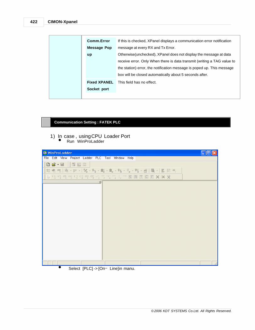
CIMON-Xpanel422
© 2006 KDT SYSTEMS Co.Ltd. All Rights Reserved.
Comm.Error
Message Pop
up
If this is checked, XPanel displays a communication error notification
message at every RX and Tx Error.
Otherwise(unchecked), XPanel does not display the message at data
receive error. Only When there is data transmit (writing a TAG value to
the station) error, the notification message is poped up. This message
box will be closed automatically about 5 seconds after.
Fixed XPANEL
Socket port
This field has no effect.
Communication Setting : FATEK PLC
1) In case , using CPU Loader Port• Run ‘WinProLadder’
• Select [PLC] -> [On Line] in manu.
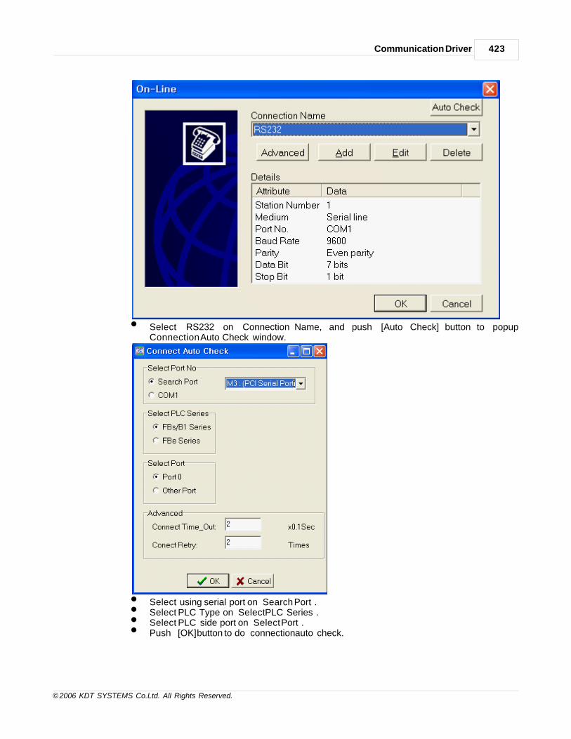
Communication Driver 423
© 2006 KDT SYSTEMS Co.Ltd. All Rights Reserved.
• Select ‘RS232’ on Connection Name, and push [Auto Check] button to popup
Connection Auto Check window.
• Select using serial port on ‘Search Port’.• Select PLC Type on ‘Select PLC Series’.• Select PLC side port on ‘Select Port’.• Push [OK] button to do connection auto check.

CIMON-Xpanel424
© 2006 KDT SYSTEMS Co.Ltd. All Rights Reserved.
• Connection finished. Select [PLC] -> [Setting] -> [Station Number] to popup ‘Station
Number’ window.
• After input PLC의 Station Number, puch [OK] button to finish.• Select Port parameter on [PLC] -> [Setting], to change port parameter.
2) IP Setting• Run ‘Fatek Ethernet Module Configuration Tool’

Communication Driver 425
© 2006 KDT SYSTEMS Co.Ltd. All Rights Reserved.
• To scan Fatek PLC, push ‘Scan Map’ button.• Double click item on scan result to edit Ethernet setting.
• [General] tab, IP and Subnet Mask, GateWay to set.• Remote Config. Enable must check.• Select Server on Operation Mode.

CIMON-Xpanel426
© 2006 KDT SYSTEMS Co.Ltd. All Rights Reserved.
• [Misc. ] tab, Major Port set on FATEK Service Port Number.• After finished parameter setting, push [OK] button.
Address Notifiation
Name Symbol Digital Analog
16 Bit 32 Bit
Input discrete X X00~X9999 WX00-WX9984 DWX00-DWX9984
Output relay Y Y00~Y9999 WY00-WY9984 DWY00-DWY9984
Internal relay M M00~M9999 WM00-WM9984 DWM00-DWM9984
Step relay S S00~S9999 WS00-WS9984 DWS00-DWS9984
Timer discrete T T00~T9999 WT00-WT9984 DWT00-DWT9984
Counterdiscrete
C C00~C9999 WC00-WC9984 DWC00-DWC9984
Timer register TMR RT00-RT9999 DRT00-DRT9999
Counter register CTR RC00-RC9999 DRC00-DRC9999
Data register HR R00-R65535 DR00-DR65535
Data register DR D00-D65535 DD00-DD65535
(1) Word tag is supported by only 16 Bit.(2) Digital address is only used to Digital tag.(3) 32Bit address is used to 32 bit Analog tag only.

Communication Driver 427
© 2006 KDT SYSTEMS Co.Ltd. All Rights Reserved.
Wiring Diagram
This interface is used to communicate between the equipment and TOUCH/PPC by Ethernet code of
practice.
This interface is satisfied with standard IEEE802.3 about the 10BaseT/100BaseTX.
You can make cable and allocation pin number of RJ45 as the following figure.
RJ45 Connector RJ45 Jack
Direct Cable: Host <-> HUB
Cable No Color Color No Cable
1 Orange/W Orange/W 1
2 Orange Orange 2
3 Green/W Green/W 3
4 Blue Blue 4
5 Blue/W Blue/W 5
6 Green Green 6
7 Brown/W Brown/W 7
8 Brown Brown 8
Crossover Cable: Host <-> Host
Cable No Color Color No Cable
1 Orange/W Green/W 1
2 Orange Green 2
3 Green/W Orange/W 3
4 Blue Blue 4
5 Blue/W Blue/W 5
6 Green Orange 6
7 Brown/W Brown/W 7
8 Brown Brown 8

CIMON-Xpanel428
© 2006 KDT SYSTEMS Co.Ltd. All Rights Reserved.
27.7 HITACHI Inverter SJ300/L300P
This driver supports the communication with Hitachi Inverter SJ300 and L300P models through RS485 port.
Communication Setup : HITACHI Inverter(SJ300/L300P)
For normal communication with Xpanel, following parameters of inverter have to be properly configured.
FunctionCode
Item Value Description
C070Data commandsource
02 Digital operator
03 RS485 connector
04 Expansion card #1
05 Expansion card #2
C071Baudrate
02 Loopback test
03 2400 bps
04 4800 bps
05 9600 bps
06 19200 bps
C072 Node address 1 to 32Node or station address(unique to each inverter or device)
C073 Data bits07 7 bits
08 8 bits
C074 Parity
00 None
01 Even parity
02 Odd parity
C075 Stop bits01 1 bit
02 2 bits
C078 Wait time0 to
10000 to 1000 ms time that the inverter waits to respond tonetwork master
Please refer to the manual of inverter for more information.
Communication Setup : Xpanel

Communication Driver 429
© 2006 KDT SYSTEMS Co.Ltd. All Rights Reserved.
Create a newdevice For creating a new device activate the menu ‘Tools’ -> ’I/O Devices’ or icon in tool-bar.
Following picture shows the first step of creating a new device.
I/O Device Name : Give a device name. This name will be used in the TAG configuration window
of database accompanied by the ‘Station Name’.
Select a devicetype
Select a device type : ' HITACHI Inverter '
After selecting the ‘OK’ button of previous step, ‘Serial Communication Configuration’ dialog
box will
be popped up as shown in following picture..

CIMON-Xpanel430
© 2006 KDT SYSTEMS Co.Ltd. All Rights Reserved.
In this window, select the ‘Device Type’ as ‘HITACHI Inverter’ and configure the proper serial
communication parameters. Ensure that those parameters are matched with the inverter's
configuration.
Create a station Move to the ‘Station’ tab of ‘Serial Communication Configuration’ dialog box.
In this dialog box, all the connected inverter stations can be configured and registered to the
Xpanel.
Each field can be configured with following rules.

Communication Driver 431
© 2006 KDT SYSTEMS Co.Ltd. All Rights Reserved.
Station Name Give a name to the inverter.
This name will be used in the database window accompanied with the ‘
Device Name’.
Station Type Choose the type of connected inverter.
Two inverter models are supported by this communication drivers (SJ300
and L300P).
Network ID This field has no effect.

CIMON-Xpanel432
© 2006 KDT SYSTEMS Co.Ltd. All Rights Reserved.
Station No. Specify a decimal number between 1 and 32. This number must be matched
with the number in the parameter of the inverter (Function code : C072).
16bits Data
Swap
This field has no effect.
32bits Data
Swap
This field has no effect.
Using
Checksum
This field has no effect.
This communication driver always checks the check-sum.
Comm. Error
Message pop
Up
If this item is checked, Xpanel displays a communication error notification
message at every Rx and Tx error.
Otherwise(unchecked), Xpanel does not display the message at data receive
error. Only when there is data transmit (writing a TAG value to the station)
error, the notification message is popped up. This message box will be closed
automatically about 5 seconds after.
Point Map
AddressNotation
[ Symbol ][ Offset ][ . ][ Bit number ]
· Symbol : A, B, C, F, H, P, X or Y
· Offset : 3 digits decimal number (001 ... ???)
· Bit number : 2 digits decimal number (00 ... 31) with proceeding dot (.)
All analog real tags must be declared as UINT32 data type for normal data processing
as shown in the following picture. And some points need the scale factor for simple and
easy data manipulation in Xpanel. The point map in the next section includes a
recommended
scale factor column for those points.

Communication Driver 433
© 2006 KDT SYSTEMS Co.Ltd. All Rights Reserved.
PointMap
Address Description Acc. Scale Cmd
A001-A393 Basic parameter setting R/W - 06(R)/07(W)
B001-B313 Fine tuning functions R/W - 06(R)/07(W)
C001-C123 Intelligent terminal functions R/W - 06(R)/07(W)
F002-F303 Main profile parameters R/W - 06(R)/07(W)
H003-H306 Motor constants R/W - 06(R)/07(W)
P001-P049 Expansion card functions R/W - 06(R)/07(W)
X001 Output frequency (x 100Hz) R 0.01 03
X002 Output current (x 10A) R 0.1 03
X003 Direction of rotation R - 03
X004 PID feedback monitor (x 100%) R 0.01 03
X005 Intelligent input monitor R - 03
X006 Intelligent output monitor R - 03
X007 Frequency converting monitor (x 100) R 0.01 03
X008 Output torque monitor (%) R - 03
X009 Output voltage monitor (x 10V) R 0.1 03
X010 Electric power monitor (x 10kW) R 0.1 03
X012 Run mode time monitor (Hours) R - 03
X013 Power ON time monitor (Hours) R - 03
X014 Trip : Inverter status A R - 04
X015 Inverter status B R - 04
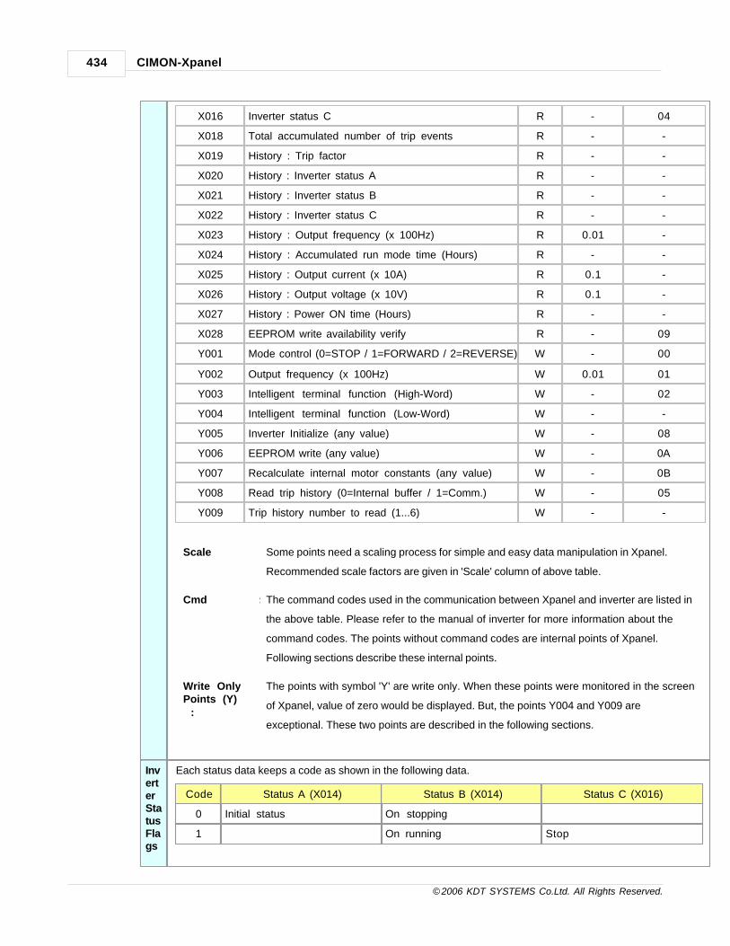
CIMON-Xpanel434
© 2006 KDT SYSTEMS Co.Ltd. All Rights Reserved.
X016 Inverter status C R - 04
X018 Total accumulated number of trip events R - -
X019 History : Trip factor R - -
X020 History : Inverter status A R - -
X021 History : Inverter status B R - -
X022 History : Inverter status C R - -
X023 History : Output frequency (x 100Hz) R 0.01 -
X024 History : Accumulated run mode time (Hours) R - -
X025 History : Output current (x 10A) R 0.1 -
X026 History : Output voltage (x 10V) R 0.1 -
X027 History : Power ON time (Hours) R - -
X028 EEPROM write availability verify R - 09
Y001 Mode control (0=STOP / 1=FORWARD / 2=REVERSE) W - 00
Y002 Output frequency (x 100Hz) W 0.01 01
Y003 Intelligent terminal function (High-Word) W - 02
Y004 Intelligent terminal function (Low-Word) W - -
Y005 Inverter Initialize (any value) W - 08
Y006 EEPROM write (any value) W - 0A
Y007 Recalculate internal motor constants (any value) W - 0B
Y008 Read trip history (0=Internal buffer / 1=Comm.) W - 05
Y009 Trip history number to read (1...6) W - -
Scale : Some points need a scaling process for simple and easy data manipulation in Xpanel.
Recommended scale factors are given in 'Scale' column of above table.
Cmd : The command codes used in the communication between Xpanel and inverter are listed in
the above table. Please refer to the manual of inverter for more information about the
command codes. The points without command codes are internal points of Xpanel.
Following sections describe these internal points.
Write OnlyPoints (Y) :
The points with symbol 'Y' are write only. When these points were monitored in the screen
of Xpanel, value of zero would be displayed. But, the points Y004 and Y009 are
exceptional. These two points are described in the following sections.
InverterStatusFlags
Each status data keeps a code as shown in the following data.
Code Status A (X014) Status B (X014) Status C (X016)
0 Initial status On stopping
1 On running Stop

Communication Driver 435
© 2006 KDT SYSTEMS Co.Ltd. All Rights Reserved.
(X014 /X015 /X016)
2 On stopping On tripping Deceleration speed
3 On running Constant speed
4 On free-run stop Acceleration speed
5 On jog Forward
6 On dynamic breaking Reverse
7 On retry Reverse from forward
8 On trip Forward from reverse
9 On under-voltage Forward start
10 Reverse start
TripHistory(Y008/Y009)
The inverter keeps total 6 trip history data on its memory. And the Xpanel driver provides a method to choose
on of those 6 trip history data for monitoring.
To monitor a trip history in Xpanel, first of all, Y009 has to be set a value between 1 and 6. This value denotes
the history data ID to be stored in X018 - X027. And then, when the Y008 point was written as zero or one,
one of history data block would be copied to the monitoring points (X018 - X027) as explained in the following
picture. When the Y008 point was written as zero (0), one of buffered trip history would be copied to the
monitoring points(X018 - X027). Otherwise (written as 1), the internal trip history data buffer would be updated
by the data from inverter.
Thus, following sequential commands or script program updates the trip history data which are stored in
X018 - X027 and monitored.

CIMON-Xpanel436
© 2006 KDT SYSTEMS Co.Ltd. All Rights Reserved.
TAG_Y009 = 1; // Set the trip history ID (1...6) TAG_Y008 = 1; // Update the history data by communication
IntelligentTerminalFunction(Y003 /Y004)
The intelligent terminal functions are composed with 64 bit control flags as listed in the following table. These
control flags are accessed by Xpanel with two different touble word points, Y003 and Y004. Y003 holds high 32
bit flags of intelligent terminal function and Y004 holds low 32 bits.
Y004 (Low) Y003 (High)
Bit No. Description Bits No. Description
00 [FW] Forward command 00 [SF1] Multi-speed bit-level
01 [RV] Reverse command 01 [SF2] Multi-speed bit-level
02 [CF1] Multi-speed 1 02 [SF3] Multi-speed bit-level
03 [CF2] Multi-speed 2 03 [SF4] Multi-speed bit-level
04 [CF3] Multi-speed 3 04 [SF5] Multi-speed bit-level
05 [CF4] Multi-speed 4 05 [SF6] Multi-speed bit-level
06 [JG] Jog operation 06 [SF7] Multi-speed bit-level
07 [DB] Dynamic braking 07 [OLR] Overload restriction setting
08 [SET] Set 2nd motor 08 [TL] Torque limit
09 [2CH] 2-stage adjustable speed 09 [TRQ1] Torque limit select 1
10 10 [TRQ2] Torque limit select 2
11 [FRS] Free-run stop 11 [PPIP/PI] Inverter model select
12 [EXP] External trip 12 [BOK] Brake confirmation
13 [USP] Unattended start protection 13 [ORT] Orientation (home) command
14 [CS] Commercial power change 14 [LAC] Linear accel/decel cancel
15 [SFT] Software lock 15 [PCLR] Position error clear
16 [AT] Analog input voltage/current 16 [STAT] Pulse train input enable
17 [SET3] Set 3rd motor 17
18 [RS] Reset 18
19 19
20 [STA] 3-wire Start 20
21 [STP] 3-wire Hold 21
22 [F/R] 3-wire FWD/REV 22
23 [PID] PID enable 23
24-31 24-31
When data were written to Y004 points, Xpanel would store the value in its memory. That is, Xpanel does not
send the Y004 data to the inverter and waits until the point Y003 is written as some other value. The actual
data sending is fulfilled when Y003 point was written as some value. Following sequential commands or script

Communication Driver 437
© 2006 KDT SYSTEMS Co.Ltd. All Rights Reserved.
program sends "forward : bit 0 of Y004", "multi-speed 1 : bit 2 of Y004" and "multi-speed 2 : bit 3
of Y004" commands to the inverter at the same time.
TAG_Y004 = 0x000D; // Set the low command flags TAG_Y003 = 0; // Set the high command flags and send commands to inverter
Wiring Diagram
RS485
Xpanel COM1 RS422/485
27.8 KDT SYSTEMS CIMON-PLC HMI (RS232C/RS422A)
This driver supports the communication with CIMON-PLC through RS232C/422A HMI Protocol. Following
modules (options) support the HMI Protocol.
* CM1-SC01A/B * CM1-SC02A
* CM1-CP4C/D/U * CM1-BPnnM option : R, S, U, T
Communication Setup : Xpanel

CIMON-Xpanel438
© 2006 KDT SYSTEMS Co.Ltd. All Rights Reserved.
Create a newdevice For creating a new device activate the menu [ Tools - I/O Devices ] or icon in tool-bar.
Following picture shows the first step of creating a new device.
I/O Device Name : Give a device name. This name will be used in the TAG configuration window
of database
accompanied by the ‘Station Name’.
Select a devicetype
Select a device type : ' KDT Systems CIMON-PLC HMI '
After selecting the ‘OK’ button of previous step, ‘Serial Communication Configuration’ dialog box will
be popped up as shown in following picture.

Communication Driver 439
© 2006 KDT SYSTEMS Co.Ltd. All Rights Reserved.
In this window, select the ‘Device Type’ as ‘KDT Systems CIMON-PLC HMI’ and configure the
proper serial
communication parameters. Ensure that those parameters are matched with PLC configuration.
Create a station Move to the ‘Station’ tab of ‘Serial Communication Configuration’ dialog box.
In this dialog box, all the connected PLC stations can be configured and registered to the Xpanel.
Each field
can be configured with following rules.

CIMON-Xpanel440
© 2006 KDT SYSTEMS Co.Ltd. All Rights Reserved.
Station Name Give a name to the PLC.
This name will be used in the database window accompanied with the
‘Device Name’.
Station Type Choose the type of connected PLC between “CP/XP Series” and “BP Series”.
Network ID This field has no effect.
Station No. Specify a decimal number between 0 and 31.
16bits Data
Swap
This field has no effect.
32bits Data
Swap
This field has no effect.
Using
Checksum
This field has no effect.

Communication Driver 441
© 2006 KDT SYSTEMS Co.Ltd. All Rights Reserved.
Comm. Error
Message pop
Up
If this item is checked, Xpanel displays a communication error notification
message at every Rx and Tx error.
Otherwise(unchecked), Xpanel does not display the message at data receive
error. Only when there is data transmit (writing a TAG value to the station)
error, the notification message is popped up. This message box will be closed
automatically about 5 seconds after.
Communication Setup : PLC
CommunicationModule
If one of the following special function modules is used for Xpanel connection, the property of module should
be configured as following picture.
· CM1-SC01A or B
· CM1-SC02A
· BPnnMxxx-U or T
The protocol item must be set as ‘HMI Protocol’. And ensure that other communication parameters are

CIMON-Xpanel442
© 2006 KDT SYSTEMS Co.Ltd. All Rights Reserved.
matched with Xpanel.
CPUEmbeddedPort
If the CPU embedded port is used for connection with Xpanel, the CPU parameter must be configured as
following picture.
This type of communication port is supported by following models :
· CM1-CP4C or D or U
· BPnnMxxx-R or S
Supported PLC Memories
Area Symbol Analog TAG Digital TAG Remark
External Input X X0000 X5110 X0000 X511F
External Output Y Y0000 Y5110 Y0000 Y511F
Internal Relay M M0000 - M9990 M0000 - M999F
Internal Relay L L0000 L9990 L0000 L999F
Latch Relay K K0000 K9990 K0000 K999F
Flags F F0000 F1270 F0000 F127F Read Only
Timer Output T Not supported T0000 T4095
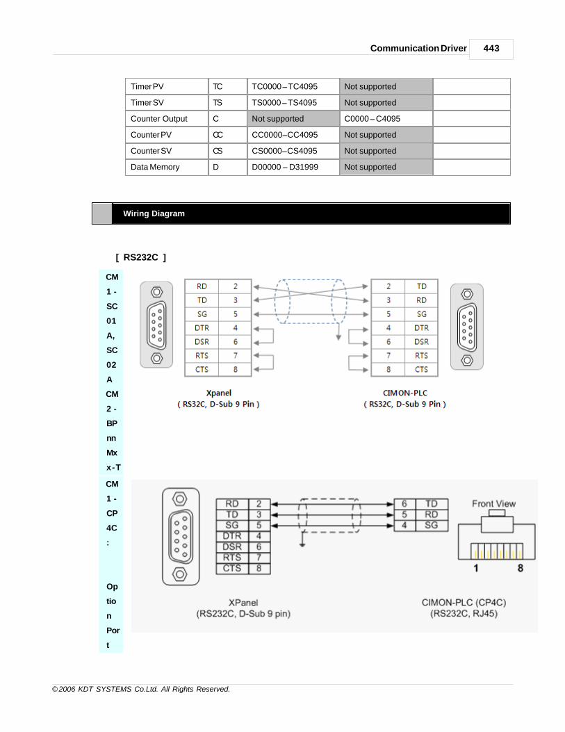
Communication Driver 443
© 2006 KDT SYSTEMS Co.Ltd. All Rights Reserved.
Timer PV TC TC0000 TC4095 Not supported
Timer SV TS TS0000 TS4095 Not supported
Counter Output C Not supported C0000 C4095
Counter PV CC CC0000 CC4095 Not supported
Counter SV CS CS0000 CS4095 Not supported
Data Memory D D00000 D31999 Not supported
Wiring Diagram
[ RS232C ]
CM
1 -
SC
01
A,
SC
02
A
CM
2 -
BP
nn
Mx
x-T
CM
1 -
CP
4C
:
Op
tio
n
Por
t

CIMON-Xpanel444
© 2006 KDT SYSTEMS Co.Ltd. All Rights Reserved.
CM
2 -
BP
16
Mx
x-R
[ RS422A ]
CM1-SC01A,
SC02A
CM1-CP4C :
Option
Port

Communication Driver 445
© 2006 KDT SYSTEMS Co.Ltd. All Rights Reserved.
CM2-BP16Mxx-S
CM2-BPnnMxx-U
27.9 KDT SYSTEMS CIMON-PLC Loader (RS232C/RS422A)
This driver supports the communication with CIMON-PLC through RS232C/422A loader protocol.
Following PLC CPU modules are connectable with this driver.
* CM1-XPnA/R * CM1CPnA/B/C/D/U
* CM2-BPnnM * CM1-SC01A/B * CM1-SC02A
Communication Setup : Xpanel
Createanewdevice
For creating a new device activate the menu [ Tools - I/O Devices ] or icon in tool-bar.
Following picture shows the first step of creating a new device.

CIMON-Xpanel446
© 2006 KDT SYSTEMS Co.Ltd. All Rights Reserved.
I/O Device Name : Give a device name. This name will be used in the TAG configuration window of
database
accompanied by the ‘Station Name’.
Selectadevicetype
Select a device type : ' KDT Systems CIMON-PLC LOADER '
After selecting the ‘OK’ button of previous step, ‘Serial Communication Configuration’ dialog box will
be
popped up as shown in following picture.

Communication Driver 447
© 2006 KDT SYSTEMS Co.Ltd. All Rights Reserved.
In this window, select the ‘Device Type’ as ‘KDT Systems CIMON-PLC Loader’ and configure the
proper
serial communication parameters. Ensure that those parameters are matched with PLC configuration.
[Note] The communication parameter of standard loader port is ‘38400-n-8-1’.
Createastation
Move to the ‘Station’ tab of ‘Serial Communication Configuration’ dialog box. In this dialog box, all
the
connected PLC stations can be configured and registered to the Xpanel. Each field can be configured
with
following rules.

CIMON-Xpanel448
© 2006 KDT SYSTEMS Co.Ltd. All Rights Reserved.
Station Name Give a name to the PLC.
This name will be used in the database window accompanied with the ‘Device
Name’.
Station Type Choose the type of connected PLC among the “CP/XP/BP Series”.
Network ID This field has no effect.
Station No. Specify a decimal number between 0 and 31. This number is effective on CPU’s
optional
port or SCnnA/B module. The station number is ignored on the standard loader
port.
16bits Data
Swap
This field has no effect.
32bits Data This field has no effect.
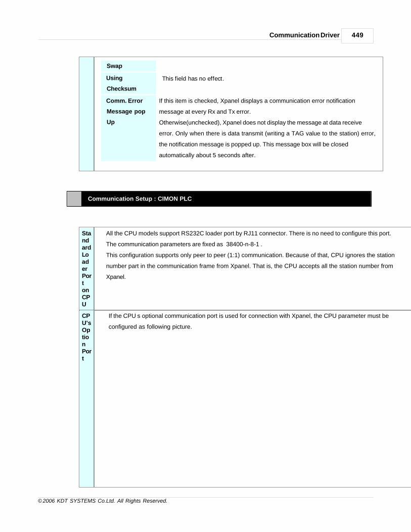
Communication Driver 449
© 2006 KDT SYSTEMS Co.Ltd. All Rights Reserved.
Swap
Using
Checksum
This field has no effect.
Comm. Error
Message pop
Up
If this item is checked, Xpanel displays a communication error notification
message at every Rx and Tx error.
Otherwise(unchecked), Xpanel does not display the message at data receive
error. Only when there is data transmit (writing a TAG value to the station) error,
the notification message is popped up. This message box will be closed
automatically about 5 seconds after.
Communication Setup : CIMON PLC
StandardLoaderPortonCPU
All the CPU models support RS232C loader port by RJ11 connector. There is no need to configure this port.
The communication parameters are fixed as ‘38400-n-8-1’.
This configuration supports only peer to peer (1:1) communication. Because of that, CPU ignores the station
number part in the communication frame from Xpanel. That is, the CPU accepts all the station number from
Xpanel.
CPU'sOptionPort
If the CPU’s optional communication port is used for connection with Xpanel, the CPU parameter must be
configured as following picture.

CIMON-Xpanel450
© 2006 KDT SYSTEMS Co.Ltd. All Rights Reserved.
Notice that the station number must be matched with that of Xpanel configuration. CP series CPU’s optional
port supports two protocols. But, there is no need to set the protocol type. This port automatically detects the
protocol type. Following CPU models support the loader protocol on the optional communication port.
· CM1-CP4C or D or U
Communication Module
If one of the following special function modules (options) is used for Xpanel connection, the property of module
should be configured as following picture.
· CM1-SC01A or B
· CM1-SC02A
· BPnnMxxx-U or T

Communication Driver 451
© 2006 KDT SYSTEMS Co.Ltd. All Rights Reserved.
The protocol item must be set as ‘CICON(Loader) Protocol’. And ensure that other communication parameters
are matched with Xpanel, especially for the station number.
Supported PLC Memories
Area Symbol Analog TAG Digital TAG Remark
External Input X X0000 X5110 X0000 X511F
External Output Y Y0000 Y5110 Y0000 Y511F
Internal Relay M M0000 - M9990 M0000 - M999F
Internal Relay L L0000 L9990 L0000 L999F
Latch Relay K K0000 K9990 K0000 K999F
Flags F F0000 F1270 F0000 F127F Read Only
Timer Output T Not supported T0000 T4095
Timer PV TC TC0000 TC4095 Not supported
Timer SV TS TS0000 TS4095 Not supported
Counter Output C Not supported C0000 C4095
Counter PV CC CC0000 CC4095 Not supported

CIMON-Xpanel452
© 2006 KDT SYSTEMS Co.Ltd. All Rights Reserved.
Counter SV CS CS0000 CS4095 Not supported
Data Memory D D00000 D31999 Not supported
Wiring Diagram
[ RS232C ]
All
CP
U
mo
del
CM
1 -
SC
01
A,
SC
02
A
CM
2 -
BP
nn
Mx
x-T
[ RS422A ]

Communication Driver 453
© 2006 KDT SYSTEMS Co.Ltd. All Rights Reserved.
CM1-SC01B,
SC02A
CM1-CP4D
CM2-BPnnMxxx-
U
27.10 KDT Systems Xpanel Master
This driver provides the network solution between Xpanels. The XPanel in which this driver was loaded is a
master station,
and other Xpanels are slave stations. All slave Xpanels should have been configured as the ‘data server’.

CIMON-Xpanel454
© 2006 KDT SYSTEMS Co.Ltd. All Rights Reserved.
(The Xpanel’s data server configuration is described in the manual of Xpanel.)
Communication Setup : Slave Xpanel
Above picture shows how to configure a slave Xpanel to the data server.
Each slave Xpanel can have up to 1000 data buffers (D000-D999) and 1000 string buffers (S000
S999).
All these buffers should be assigned to their appropriate TAGs as shown in above picture.
For more information, please refer to the ‘Network Data Server’ section of Xpanel manual.
Communication Setup : Master Xpanel

Communication Driver 455
© 2006 KDT SYSTEMS Co.Ltd. All Rights Reserved.
Create a newdevice For creating a new device activate the menu ‘Tools’- >’I/O Devices’ or icon in tool-bar.
Following picture shows the first step of creating a new device.
I/O Device Name : Give a device name. This name will be used in the TAG configuration window
of
database accompanied by the ‘Station Name’.
Select anetwork type
Select a network type : ' KDT Systems Xpanel '
After selecting the ‘OK’ button of previous step, ‘Ethernet Communication Configuration’ dialog
box will be popped
up as shown in following picture. In this window, select the ‘Device Type’ as ‘KDT Systems
Xpanel’ and configure
the proper Ethernet communication parameters.
Point
XPanel network data server supports only UDP/IP protocol suit .
Do not select the ‘TCP’ protocol of configuration dialog box.

CIMON-Xpanel456
© 2006 KDT SYSTEMS Co.Ltd. All Rights Reserved.
Create a station Move to the ‘Station’ tab of ‘Ethernet Communication Configuration’ dialog box.
In this dialog box, all the connected PLC stations can be configured and registered to the Xpanel.
Each field can be configured with following rules.

Communication Driver 457
© 2006 KDT SYSTEMS Co.Ltd. All Rights Reserved.
Station Name Give a name to the PLC. This name will be used in the database window
accompanied with the ‘Device Name’.
Station Type Choose the ‘XPANEL’. (No other type can be selected.)
Network ID This field has no effect.
IP Address Give the IP address of the server (slave) Xpanel with dotted decimal format.
Socket Port
Nimber
Give the port number of data server serviced by the Xpanel. This value must
be 10262.
16Bit Data
Swap
This field has no effect.
32Bit Data
Swap
This field has no effect.
Comm. Error
Message Pop
Up
If this item is checked, Xpanel displays a communication error notification
message at every Rx and Tx error.
Otherwise(unchecked), Xpanel does not display the message at data
receive error. Only when there is data transmit (writing a TAG value to the
station) error, the notification message is popped up. This message box will
be closed automatically about 5 seconds after.
Fixed XPANEL Do not use this option (leave as unchecked). The server (slave) XPanel can

CIMON-Xpanel458
© 2006 KDT SYSTEMS Co.Ltd. All Rights Reserved.
Socket Port /
XPANEL Socket
Port No.
service multiple masters and dynamic socket port.
Address Notation
The address of TAG in master Xpanel has the following format.
Type Format Example
Number [D][Address in decimal number] D0012
String [S][Address in decimal number] S0100
Following table shows the list of devices which can be referenced in Xpanel database.
Memory Area Symbol I/O Address Range Applicable TAG
Real Data D D000 D999 Digital / Analog
String Data S S000 S999 String
Communication Cable Wiring

Communication Driver 459
© 2006 KDT SYSTEMS Co.Ltd. All Rights Reserved.
27.11 Keyence KV Mode
This driver provides the software interface and communication protocol between Xpanel and Keyence KVseries PLCs. It supports the following families of Keyence PLCs.
· KV-10, KV-16, KV-24, KV-40
· KV-300 with KV-L2 in KV mode
Communication Setup : Xpanel
Createanewdevice
For creating a new device activate the menu ‘Tools’->’I/O Devices’ or icon in tool-bar.
Following picture shows the first step of creating a new device.
I/O Device Name : Give a device name. This name will be used in the TAG configuration window of
database accompanied by the ‘Station Name’.
Select
Select a network type : ' KEYENCE PLC(KV mode) '

CIMON-Xpanel460
© 2006 KDT SYSTEMS Co.Ltd. All Rights Reserved.
anetworktype
After selecting the ‘OK’ button of previous step, ‘Serial Communication Configuration’ dialog box will
be
popped up as shown in following picture.
In this window, select the ‘Device Type’ as ‘KEYENCE PLC (KV mode)’ and configure the proper
serial
communication parameters. The parity is fixed as 'Even' in case of KV-10, KV-16, KV-40 PLC
module.
Createastation
Move to the ‘Station’ tab of ‘Serial Communication Configuration’ dialog box.
In this dialog box, all the connected PLC stations can be configured and registered to the Xpanel.
Each field can be configured with following rules.

Communication Driver 461
© 2006 KDT SYSTEMS Co.Ltd. All Rights Reserved.
Station Name Give a name to the PLC.
This name will be used in the database window accompanied with the ‘Device
Name’.
Station Type Choose the ‘KEYENCE KV’. (No other type can be selected.)
Network ID This field has no effect.
Station No Specify a decimal number between 0 and 9.
16Bits Data
Swap
This field has no effect.
32Bits Data
Swap
This field has no effect.
Using
Checksum
This field has no effect.
Comm. Error If this item is checked, Xpanel displays a communication error notification

CIMON-Xpanel462
© 2006 KDT SYSTEMS Co.Ltd. All Rights Reserved.
Message pop
Up
message
at every Rx and Tx error.
Otherwise(unchecked), Xpanel does not display the message at data receive
error.
Only when there is data transmit (writing a TAG value to the station) error, the
notification
message is popped up. This message box will be closed automatically about 5
seconds
after.
Address Notation
The address of TAG in Xpanel has the following format.
TAG Type Format Example
Analog [Symbol][Address] DM0012
Digital [Symbol][Address] R0215
· Address : decimal number
Following table shows the list of devices which can be referenced in Xpanel database.
Symbol Description AddressRange
Type Access
CC Counter : Current Value 0-249 Analog R/W
CP Counter : Preset Value 0-249 Analog R/W
C Counter Contact 0-249 Digital R/W
CTHC High Speed Counter : Current Value 0 - 1 Analog R/W
CTHP High Speed Counter : Preset Value 0 - 1 Analog R
CTH High Speed Counter : Contact 0 - 1 Digital R
CTCC High Speed Counter Comparator : Current Value 0 - 3 Analog R
CTCP High Speed Counter Comparator : Preset Value 0 - 3 Analog R/W
CTC High Speed Counter Comparator : Contact 0 - 3 Digital R/W
TC Timer : Current Value 0-249 Analog R/W
TP Timer : Preset Value 0-249 Analog R/W
T Timer : Contact 0-249 Digital R/W
TM Temporary Data Memory 0 31 Analog R/W
DM Data Memory 0 - 1999 Analog R/W

Communication Driver 463
© 2006 KDT SYSTEMS Co.Ltd. All Rights Reserved.
R Relay (I/O, Internal AUX, Special AUX) 0-17915 Digital R/W
AT Digital Trimmer 0 - 1 Analog R
Keyence KV mode protocol does not support block data read and write functions.
Because of that, double word (INT32, UINT32, BCD32, UBCD32, FLOAT) data types are not supported.
Ensure that especially for using following functions of Xpanel.
· Recipe
· XY / SPC / Scope Trend.
Communication Cable Wiring
KV-
10,
KV
-
16,
KV-
24,
KV
- 4 0
KV-
L2
mo
dul
e
of
KV-
30
0

CIMON-Xpanel464
© 2006 KDT SYSTEMS Co.Ltd. All Rights Reserved.
27.12 KOYO DirectNet
This Manual explains about the method of CIMON-Xpanel communication with KOYO DL06 PLC using RS232Cor RS422/485.
Communication Setup : Xpanel
You can configure I/O device according to various kind of field equipment's by using Xpanel Designer.
Configure the option of the example followed. More details about I/O device configuration in section “I/O
device configuration”.
Create a newdevice
To configure the communication device of DL06 PLC, Select 'Tools' -> 'I/O device' in the menu
or icon
in tool-bar , and then “I/O device configuration” dialog box will be shown up. And then
click
'new device' button. “I/O device selection” dialog box is shown up, select a device name and a
device
type as the following figure.

Communication Driver 465
© 2006 KDT SYSTEMS Co.Ltd. All Rights Reserved.
I/O Device Name : In the case there are various kinds of field equipments, Type device name
to identify what
equipments it is. The string “DEV” of this item will be shown up in the
selection list of
I/O device when you register a tag. Xpanel can communicate with various
kinds of equipment
simultaneously connected by identifying equipment by its name. The value
which is saved as
a tag is the compound string of a device name and station name as following
“DEV.ST”
(“DEV” is a device name, and “ST” is a station name). And it is used as a
unique identifier in
Xpanel project.
Select anetwork type
Select a network type : ' KOYO DirecNet '
You can select communication device which is connected to Xpanel.

CIMON-Xpanel466
© 2006 KDT SYSTEMS Co.Ltd. All Rights Reserved.
Comm.Port COM1
Select communication port to communicate. If you use RS-485, you must
select “COM1”. When RS-232 communication type of COM1 port is used,
9P DSUB connector is used. And When RS-422/485 communication type
of COM1 port is used, 5P plug connector is used. If you use COM1 port,
you cannot use RS-232 and RS-422/485 together, but you can use only
one type.
Baud rate 9,600
Select the communication speed to equipment. The configuration of the
communication speed of Xpanel must be the same as the configuration of
equipment. If speed of the configurations of two sides are not same, they

Communication Driver 467
© 2006 KDT SYSTEMS Co.Ltd. All Rights Reserved.
will not be communicated each other.
Parity Odd
Data bits 8 bits
Stop bits 1 bits
RTS/CTS OFF
RTS/CTS control is used for HALF-DUPLEX communication. When you
ordinary modem of two-wire circuit, you can control the modem by this
implement. Because of RS-485 communication port of the Xpanel
supports Auto Toggle function so Xpanel doesn’t use this function. This
example doesn’t use RTS-CTS control.
Comm.Type RS232
When you use RS-422 communication select RS-422 or you use RS-485
communication then select RS-485. When RS-232 communication is
used, 9P DSUB connector is used. And When RS-422/485 communication
is used, 5P plug connector is used.
Retry No. 3 (If communication failed with the kind of field equipment, it will retry as
the number of this.)
Time Out 30 (If you input as the number of 30 then it’s time out count will be 30
seconds. )
Using Dial Up
Modem
Not Select (This item can be chosen only when you use Dial Up modem.)
Create a station Move to [Station] tab at the “Serial Communication Configuration” Dialog Box and click [Add
Station] button then you can see “Station” Dialog Box popped up. Please configuration as the
following contents then click “OK” button.
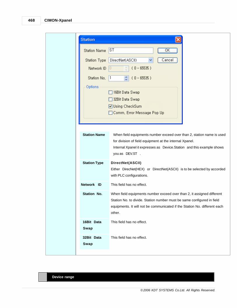
CIMON-Xpanel468
© 2006 KDT SYSTEMS Co.Ltd. All Rights Reserved.
Station Name When field equipments number exceed over than 2, station name is used
for division of field equipment at the internal Xpanel.
Internal Xpanel it expresses as “Device.Station” and this example shows
you as “DEV.ST” .
Station Type DirectNet(ASCII)
Either “DirecNet(HEX)” or “DirectNet(ASCII)” is to be selected by accorded
with PLC configurations.
Network ID This field has no effect.
Station No. When field equipments number exceed over than 2, it assigned different
Station No. to divide. Station number must be same configured in field
equipments. It will not be communicated if the Station No. different each
other.
16Bit Data
Swap
This field has no effect.
32Bit Data
Swap
This field has no effect.
Device range

Communication Driver 469
© 2006 KDT SYSTEMS Co.Ltd. All Rights Reserved.
When you edit the tag or communication block, you can edit address as following figure.
Memory Type Discrete Memory Reference(octal) Word memory Reference(octal)
Input Point X0 - X777 V40400 - v40437
Output Point Y0 - Y777 V40500 - V40537
Control Relays C0 - C1777 V40600 - V40677
Special Relays SP0 - SP777 V41200 - V41237
Timer Current Values
(Analog)
TA0 - TA377 V0 - V377
Timer Status Bits T0 - T377 V41100 - V41117
Counter Current Values
(Analog)
CTA0 - CTA177 V1000 - V1177
Counter Status Bits CT0 - CT177 V41140 - V41147
Stage S0 - S1777 V41000 - V41017
Remote I/O GX0 - GX3777
GY0 - GY3777
V40000 - V40177
V40200 - V40377
Above the address table is a basis of the company of Koyo’s DL06.
If the Equipment used DirectNET Excepted of the Koyo’s DL06, DL405, DL205 then you reference this
manual and so you can use Word memory Reference only.
Case of Digital Tag
· In the case of Word memory Reference [Ex.] At the 15 bit of the No.40000 -> V40000.15
[Ex.] 0 bit of the No.40000 -> V40000.15
· In the case of Discrete Memory Reference [EX.] At the 15 bit of the No.40000 -> GX017
(reference 129-12)
27.13 LSIS GLOFA Cnet
This Manual explains about the method of CIMON-Xpanel communication with LSIS GLOFA PLC using RS232C orRS422/485.
Communication Setup : Xpanel
You can configure I/O device according to various kind of field equipments by using Xpanel Designer.
Configure the option of the example followed. More details about I/O device configuration in section “I/O

CIMON-Xpanel470
© 2006 KDT SYSTEMS Co.Ltd. All Rights Reserved.
device configuration”.
Create a newdevice
To configure the communication device of LSIS PLC, Select 'Tools' -> 'I/O device' in the menu
or icon in
tool-bar , and then “I/O device configuration” dialog box will be shown up. And then click [new
device] button.
“I/O device selection” dialog box is shown up, select a device name and a device type as the
following figure.
I/O Device Name : In the case there are various kinds of field equipments, Type device name
to identify what equipments it is. The string “DEV” of this item will be shown up in the
selection list of I/O device when you register a tag. Xpanel can communicate with various
kinds of equipment simultaneously connected by identifying equipment by its name. The
value which is saved as a tag is the compound string of a device name and station name as
following “DEV.ST” (“DEV” is a device name, and “ST” is a station name). And it is used as
a unique identifier in Xpanel project.

Communication Driver 471
© 2006 KDT SYSTEMS Co.Ltd. All Rights Reserved.
Select a devicetype
Select a device type : ' LSIS GLOFA PLC '
You can select communication device which is connected to Xpanel.
Comm.Port COM1
Select communication port to communicate. If you use RS-422/485, you
must select “COM1”. When RS-232 communication type of COM1 port is
used, 9P DSUB connector is used. And When RS-422/485 communication
type of COM1 port is used, 5P plug connector is used. If you use COM1
port, you cannot use RS-232 and RS-422/485 together, but you can use
only one type.

CIMON-Xpanel472
© 2006 KDT SYSTEMS Co.Ltd. All Rights Reserved.
Baud rate 9,600
Select the communication speed to equipment. The configuration of the
communication speed of Xpanel must be the same as the configuration of
equipment. If speed of the configurations of two sides are not same, they
will not be communicated each other.
Parity None
Data bits 8 bits
Stop bits 1 bits
RTS/CTS OFF
RTS/CTS control is used for HALF-DUPLEX communication. When you
ordinary modem of two-wire circuit, you can control the modem by this
implement. Because of RS-485 communication port of the Xpanel supports
Auto Toggle function so Xpanel doesn’t use this function. This example
doesn’t use RTS-CTS control.
Retry No. 3
If communication failed with the kind of field equipments, it will retry as
the number of this.
Time Out 30 (If you input as the number of 30 then it’s time out count will be 30
seconds. )
Using Dial Up
Modem
Not Select (This item can be chosen only when you use Dial Up modem.)
Create a station Move to [Station] tab at the “Serial Communication Configuration” Dialog Box and click [Add
Station] button then you can see “Station” Dialog Box popped up. Please configuration as the
following contents then click “OK” button.

Communication Driver 473
© 2006 KDT SYSTEMS Co.Ltd. All Rights Reserved.
Station Name ST
When field equipments number exceed over than 2, station name is used
for division of field equipment at the internal Xpanel.
Internal Xpanel it expresses as “Device.Station” and this example shows
you as “DEV.ST” .
Station Type DirectNet
Network ID This field has no effect.
Station No. 0
When field equipments number exceed over than 2, it assigned different
Station No. to divide. Station number must be same configured in field
equipments. It will not be communicated if the Station No. different each
other.
16Bit Data
Swap
This field has no effect.
32Bit Data
Swap
This field has no effect.
Parameter Setup : Cnet Frame Editor

CIMON-Xpanel474
© 2006 KDT SYSTEMS Co.Ltd. All Rights Reserved.
Run Cnet FrameEditor
Please run ‘Cnet Frame Editor’ from GLOFA Loader and activate I/O configurations.
Channel RS232 side
To Communicate by RS/232, select the Button ‘RS232 side’.
Station 00
Configure Station number to 00. When field equipments number exceed
over than 1, it assigned different Station No. to divide. It will not be
communicated if the Station No. different each other. The way of wiring
will be following.
Baud Rate 9600
Data Bit 8 bits
Parity NONE
Cnet FrameEditor
If all configurations were ended, select [Online] [Write] in the menu.

Communication Driver 475
© 2006 KDT SYSTEMS Co.Ltd. All Rights Reserved.
Select the proper slot which was located Cnet module and click [Write].
Wiring Diagram
You can wire communication cable as the following figures.
RS-232C : NULL MODEM
Xpanel connects three lines to PLC. PLC connects lines such as above figure. If you don’t
connect lines to PLC as the showing figure, it can’t transmit data to other field equipments
but can receive data so that not to be accomplished communication.
RS-422

CIMON-Xpanel476
© 2006 KDT SYSTEMS Co.Ltd. All Rights Reserved.
On wiring as the above figure terminal resistance must be 330Ω.
To improve stability of communication it should connect SG and use STP cable.
But shielded cables must be earthed.
RS-485
On wiring as above the figure terminal resistance must be 120Ω.
When Xpanel is using RS-485, it connect with SDA and SDB but disconnect with RDA and
RDB.
To improve stability of communication it should connect SG and use STP cable.
But shielded cables must be earthed.
Device Memory range
You can use device memories as following range.
Direct Variable Data type Remark
%QX0.0.0 - %QX63.7.63 BIT Output image area
%IX0.0.0 - %QX63.7.63 BIT Input image area
%MX0 - %MX524287 BIT Direct variable area
%MW0.0 - %MW32767.15 BIT Direct variable area
%MD0.0 - %MD16383.31 BIT Direct variable area
%QW0.0.0 - %QW63.7.3 WORD Output image area

Communication Driver 477
© 2006 KDT SYSTEMS Co.Ltd. All Rights Reserved.
%IW0.0.0 - %QW63.7.3 WORD Input image area
%MW0 - %MX32767 WORD Direct variable area
%QD0.0.0 - %QD63.7.1 DWORD Output image area
%ID0.0.0 - %QD63.7.1 DWORD Input image area
%MD0 - %MD16383 DWORD Direct variable area
Error Code
When Xpanel communicates with PLC it can receive NAK including error code.
Reference Error code contents as following table.
ErrorCode
Error type Error factors and contents
0001 PLC system Error Interface failed with PLC
0011 Data Error In case of data length was wrong
In case of it doesn’t start with ‘%’
In case of variable value was wrong
If the case of Bit value write, you must write 00 or 01 but
you write other value
1132 Device memory Error In case of unusable characters were inputted
1232 Data magnitude Error In case of Read/Write requesting was over 60 Words
1332 Data type inconformity When it does doing each case of Read/Write, if the data type
of each block was dislike then it will be happen.
1432 Data value Error Unable to transform Data value to Hex
7132 permitted range of variable
over Error
Over requesting through each device supports memory
range.
27.14 LSIS GLOFA Enet
This Manual explains about the method of CIMON-Xpanel communication with LSIS GLOFA PLC using Ethernet.
Communication Setup : Xpanel

CIMON-Xpanel478
© 2006 KDT SYSTEMS Co.Ltd. All Rights Reserved.
Create a newdevice
To configure the communication device of LGIS PLC, Select 'Tools' -> 'I/O device' in the menu or
icon in tool-bar, and then “I/O device configuration” dialog box will be shown up. And then click
[new device] button. “I/O device selection” dialog box is shown up, select a device name and a
device type as the following figure.
I/O Device Name : In the case there are various kinds of field equipments, Type device name to
identify what equipments it is. The string “DEV” of this item will be shown up in the selection
list of I/O device when you register a tag. Xpanel can communicate with various kinds of
equipment simultaneously connected by identifying equipment by its name. The value which is
saved as a tag is the compound string of a device name and station name as following “DEV.
ST” (“DEV” is a device name, and “ST” is a station name). And it is used as a unique identifier
in Xpanel project.
Select a devicetype
Select a device type: LSIS GLOFA PLC
You can select communication device which is connected to Xpanel.

Communication Driver 479
© 2006 KDT SYSTEMS Co.Ltd. All Rights Reserved.
Protocol UDP
You can choose one of the protocols - UPD, TCP when you use Ethernet.
Because the size of data which is used in normal industry is small, UDP is
generally used. TCP is efficient for transferring big sized data.
Retry No. 3
If communication failed with the kind of field equipments, it will retry as the
number of this.
Create a station Move to [Station] tab at the “Serial Communication Configuration” Dialog Box and click [Add Station]
button then you can see “Station” Dialog Box popped up. Please configuration as the following
contents then click “OK” button.

CIMON-Xpanel480
© 2006 KDT SYSTEMS Co.Ltd. All Rights Reserved.
Station Name When field equipments number exceed over than 2, station name is used for
division of field equipment at the internal Xpanel. Internal Xpanel it expresses
as “Device.Station” and this example shows you as “DEV.ST” .
Station Type GLOFA
Network ID This field has no effect.
IP Address 172.16.106.254
Exactly input the field equipment’s IP address which is identified. If IP
address is not correct, it will not be communicated.
Socket Port No. 2005
The exclusive use of GLOFA Enet supporting socket number is TCP 2004,
UDP 2005.
16Bit Data
Swap
This field has no effect.
32Bit Data
Swap
This field has no effect.

Communication Driver 481
© 2006 KDT SYSTEMS Co.Ltd. All Rights Reserved.
Parameter Setup : Enet Frame Editor
Run Enet FrameEditor
Please run ‘Enet Frame Editor’ from GLOFA Loader and activate I/O configurations.
PLC Type GM1 / 2 / 3 (Select proper PLC which is using the same PLC.)
IP Address 172.16.106.254
Please input the correct IP address which is corresponded with
already configured by Xpanel Designer.
Subnet Mask 255.255.0.0
Please input the correct Subnet Mask which is corresponded with
already configured by Xpanel Designer.
GateWay 172.16.100.1
If field equipment is connected out of the Local network, you must
input IP address of GateWay.
Enet Frame If all configurations were ended, select 'Online Write' in the menu.

CIMON-Xpanel482
© 2006 KDT SYSTEMS Co.Ltd. All Rights Reserved.
Editor: Write
Select the proper slot which was located Enet module and click [Write].
Wiring Diagram
This interface is used to communicate between the equipment and TOUCH/PPC by Ethernet code of
practice.
This interface is satisfied with standard IEEE802.3 about the 10BaseT/100BaseTX.
You can make cable and allocation pin number of RJ45 as the following figure.
RJ45 Connector RJ45 Jack
Direct Cable: Host <-> HUB
Cable No Color Color No Cable
1 Orange/W Orange/W 1
2 Orange Orange 2
3 Green/W Green/W 3
4 Blue Blue 4
5 Blue/W Blue/W 5

Communication Driver 483
© 2006 KDT SYSTEMS Co.Ltd. All Rights Reserved.
6 Green Green 6
7 Brown/W Brown/W 7
8 Brown Brown 8
Crossover Cable: Host <-> Host
Cable No Color Color No Cable
1 Orange/W Green/W 1
2 Orange Green 2
3 Green/W Orange/W 3
4 Blue Blue 4
5 Blue/W Blue/W 5
6 Green Orange 6
7 Brown/W Brown/W 7
8 Brown Brown 8
Device Memory ramge
You can use device memories as following range.
Direct Variable Data type Remark
%QX0.0.0 - %QX63.7.63 BIT Output image area
%IX0.0.0 - %QX63.7.63 BIT Input image area
%MX0 - %MX524287 BIT Direct variable area
%MW0.0 - %MW32767.15 BIT Direct variable area
%MD0.0 - %MD16383.31 BIT Direct variable area
%QW0.0.0 - %QW63.7.3 WORD Output image area
%IW0.0.0 - %QW63.7.3 WORD Input image area
%MW0 - %MX32767 WORD Direct variable area
%QD0.0.0 - %QD63.7.1 DWORD Output image area
%ID0.0.0 - %QD63.7.1 DWORD Input image area
%MD0 - %MD16383 DWORD Direct variable area
Error Code
When Xpanel communicates with PLC it can receive NAK including error code.
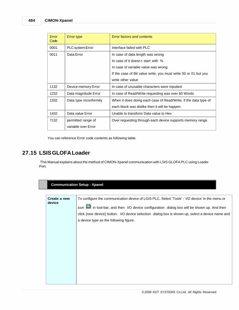
CIMON-Xpanel484
© 2006 KDT SYSTEMS Co.Ltd. All Rights Reserved.
ErrorCode
Error type Error factors and contents
0001 PLC system Error Interface failed with PLC
0011 Data Error In case of data length was wrong
In case of it doesn’t start with ‘%’
In case of variable value was wrong
If the case of Bit value write, you must write 00 or 01 but you
write other value
1132 Device memory Error In case of unusable characters were inputted
1232 Data magnitude Error In case of Read/Write requesting was over 60 Words
1332 Data type inconformity When it does doing each case of Read/Write, if the data type of
each block was dislike then it will be happen.
1432 Data value Error Unable to transform Data value to Hex
7132 permitted range of
variable over Error
Over requesting through each device supports memory range.
You can reference Error code contents as following table.
27.15 LSIS GLOFA Loader
This Manual explains about the method of CIMON-Xpanel communication with LSIS GLOFA PLC using LoaderPort.
Communication Setup : Xpanel
Create a newdevice
To configure the communication device of LGIS PLC, Select 'Tools' -' I/O device' in the menu or
icon in tool-bar, and then “I/O device configuration” dialog box will be shown up. And then
click [new device] button. “I/O device selection” dialog box is shown up, select a device name and
a device type as the following figure.

Communication Driver 485
© 2006 KDT SYSTEMS Co.Ltd. All Rights Reserved.
I/O Device Name : In the case there are various kinds of field equipments, Type device name
to identify what equipments it is. The string “DEV” of this item will be shown up in the
selection list of I/O device when you register a tag. Xpanel can communicate with various
kinds of equipment simultaneously connected by identifying equipment by its name. The
value which is saved as a tag is the compound string of a device name and station name as
following “DEV.ST” (“DEV” is a device name, and “ST” is a station name). And it is used as
a unique identifier in Xpanel project.
Select a devicetype
Select a device type : LSIS GLOFA PLC Loader
You can select communication device which is connected to Xpanel.

CIMON-Xpanel486
© 2006 KDT SYSTEMS Co.Ltd. All Rights Reserved.
Comm.Port COM1
Select communication port to communicate. If you use RS-422/485, you
must select “COM1”. When RS-232 communication type of COM1 port is
used, 9P DSUB connector is used. And When RS-422/485 communication
type of COM1 port is used, 5P plug connector is used. If you use COM1
port, you cannot use RS-232 and RS-422/485 together, but you can use
only one type.
Baud rate 38,400

Communication Driver 487
© 2006 KDT SYSTEMS Co.Ltd. All Rights Reserved.
Select the communication speed to equipment. The configuration of the
communication speed of Xpanel must be the same as the configuration of
equipment. If speed of the configurations of two sides are not same, they
will not be communicated each other.
Parity None
Data bits 8 bits
Stop bits 1 bits
RTS/CTS OFF
Retry No. 3
If communication failed with the kind of field equipments, it will retry as
the number of this.
Time Out 3 0
If you input as the number of 30 then it’s time out count will be 30
seconds.
Using Dial Up
Modem
Not Select
This item can be chosen only when you use Dial Up modem.
Create a station Move to [Station] tab at the “Serial Communication Configuration” Dialog Box and click [Add
Station] button then you can see “Station” Dialog Box popped up. Please configuration as the
following contents then click “OK” button.
Station Name When field equipments number exceed over than 2, station name is used

CIMON-Xpanel488
© 2006 KDT SYSTEMS Co.Ltd. All Rights Reserved.
for division of field equipment at the internal Xpanel.
Internal Xpanel it expresses as “Device.Station” and this example shows
you as “DEV.ST” .
Station Type GLOFA
Network ID This field has no effect.
Station No. 0
16Bit Data
Swap
This field has no effect.
32Bit Data
Swap
This field has no effect.
Wiring Diagram
You can wire communication cable as the following figures.
Xpanel connects three lines to PLC. PLC connects lines such as above figure. You must connect using three
lines.
If you connect other lines it can make problems.
Device Memory range
You can use device memories as following range.

Communication Driver 489
© 2006 KDT SYSTEMS Co.Ltd. All Rights Reserved.
Direct Variable Data type Remark
%QX0.0.0 - %QX63.7.63 BIT Output image area
%IX0.0.0 - %QX63.7.63 BIT Input image area
%MX0 - %MX524287 BIT Direct variable area
%MW0.0 - %MW32767.15 BIT Direct variable area
%MD0.0 - %MD16383.31 BIT Direct variable area
%QW0.0.0 - %QW63.7.3 WORD Output image area
%IW0.0.0 - %QW63.7.3 WORD Input image area
%MW0 - %MX32767 WORD Direct variable area
%QD0.0.0 - %QD63.7.1 DWORD Output image area
%ID0.0.0 - %QD63.7.1 DWORD Input image area
%MD0 - %MD16383 DWORD Direct variable area
27.16 LSIS XGT Cnet
This Manual explains about the method of CIMON-Xpanel communication with LSIS GLOFA PLC using RS232C orRS422/485.
Communication Setup : Xpanel
Create a newdevice
To configure the communication device of LSIS PLC, Select 'Tools' - 'I/O device' in the menu or
icon in tool-bar, and then “I/O device configuration” dialog box will be shown up. And then
click [new device] button. “I/O device selection” dialog box is shown up, select a device name and
a device type as the following figure.

CIMON-Xpanel490
© 2006 KDT SYSTEMS Co.Ltd. All Rights Reserved.
I/O Device Name : In the case there are various kinds of field equipments, Type device name
to identify what equipments it is. The string “XGTCNET” of this item will be shown up in the
selection list of I/O device when you register a tag. Xpanel can communicate with various
kinds of equipment simultaneously connected by identifying equipment by its name. The
value which is saved as a tag is the compound string of a device name and station name as
following “XGTCNET.ST” (“XGTCNET” is a device name, and “ST” is a station name). And it
is used as a unique identifier in Xpanel project.
Select a devicetype
Select a device type : ' LSIS XGT/XGB Series PLC Cnet '
You can select communication device which is connected to Xpanel.

Communication Driver 491
© 2006 KDT SYSTEMS Co.Ltd. All Rights Reserved.
Comm.Port COM1
Select communication port to communicate. This example shows you
selecting COM1 port. If you want use other port select one in this combo
box.
Baud rate 38,400
Parity None
Data bits 8 bits
Stop bits 1 bits

CIMON-Xpanel492
© 2006 KDT SYSTEMS Co.Ltd. All Rights Reserved.
RTS/CTS OFF ( This example doesn’t use RTS-CTS control.)
Comm. Type RS232
(To Communicate by RS/232, configure Type to RS-232.
When you use RS-422 communication select RS-422 or you use RS-485
communication then select RS-485.)
Retry No. 3
If communication failed with the kind of field equipments, it will retry as
the number of this.
Time Out 30
(If you input as the number of 30 then it’s time out count will be 30
seconds..)
Using Dial Up
Modem
Not Select
This item can be chosen only when you use Dial Up modem.
Create a station Move to [Station] tab at the “Serial Communication Configuration” Dialog Box and click [Add
Station] button then you can see “Station” Dialog Box popped up. Please configuration as the
following contents then click “OK” button.
Station Name When field equipments number exceed over than 2, station name is used
for division of field equipment at the internal Xpanel.
Internal Xpanel it expresses as “Device.Station” and this example shows
you as “XGTCNET.ST”.
Station Type XGT Series

Communication Driver 493
© 2006 KDT SYSTEMS Co.Ltd. All Rights Reserved.
Network ID This field has no effect.
Station No. When field equipments number exceed over than 2, it assigned different
Station No. to divide. Station number must be same configured in field
equipments. It will not be communicated if the Station No. different each
other.
16Bit Data
Swap
This field has no effect.
32Bit Data
Swap
This field has no effect.
Parameter Setup : Network Manager
Run NetworkManager
Please run ‘Network Manager’ from XGT Loader program and activate I/O configurations.

CIMON-Xpanel494
© 2006 KDT SYSTEMS Co.Ltd. All Rights Reserved.
Comm.Type RS232C
To Communicate by RS/232, configure Type to RS-232 at Channel 1.
When you use RS-422 communication select RS-422 or you use RS-
485 communication then select RS-485.
Speed 38,400
Data Bit 8
Stop Bit 1
Parity NONE
Modem type Null Modem
Modem
Initialization
This field has no effect.

Communication Driver 495
© 2006 KDT SYSTEMS Co.Ltd. All Rights Reserved.
Station No. 0
Station No. needed to distinguish when it communicate several PLC.
When field equipments number exceed over than 2, it assigned
different Station No. to divide. Station number must be same
configured in field equipments. It will not be communicated if the
Station No. different each other.
Delay time 0
Time out 1
Wiring Diagram
You can wire communication cable as the following figures.
RS-232C
RS-422
On wiring as the above figure terminal resistance must be 330Ω.
To improve stability of communication it should connect SG and use STP cable.

CIMON-Xpanel496
© 2006 KDT SYSTEMS Co.Ltd. All Rights Reserved.
But shielded cables must be earthed.
RS-485
On wiring as above the figure terminal resistance must be 120Ω.
When Xpanel is using RS-485, it connects with SDA and SDB but disconnect with
RDA and RDB.
To improve stability of communication it should connect SG and use STP cable.
But shielded cables must be earthed.
Device Memory range
Usable device memory range
You can use device memories as following range.
Type Range Size (Word) Remark
P P0 P2047 2048 Read/Write/Monitor
M M0 M2047 2048 Read/Write/Monitor
L L0 L11263 11264 Read/Write/Monitor
K K0 K2047 2048 Read/Write/Monitor
F F0 F2047 2048 Read/Monitor
T T0 T2047 2048 Read/Write/Monitor
C C0 C2047 2048 Read/Write/Monitor
D D0 D32767 32768 Read/Write/Monitor (XGK-CPUH)
D0 D19999 20000 Read/Write/Monitor (XGK-CPUS)
S S0 S127 128 Read/Write/Monitor
Error Code

Communication Driver 497
© 2006 KDT SYSTEMS Co.Ltd. All Rights Reserved.
When Xpanel communicates with PLC it can receive NAK including error code.
Reference Error code contents as following table.
Error Code Error type Error factors and contents
0003 Over block number It is block number bigger than 16 in the case of individual
Read/Write requesting.
0004 Variable length error Variable length is over than its max size 16.
0007 Data type error Receiving data is not included in X,B,W,D,L
0011 Data error The memory address that including the length of data is
incorrect
In the case of starting without %
In the case of variable value is incorrect.
When you write a Bit Value, you must use only 0 or 1.
0090 Monitor In the case of executing unregistered Monitor
0190 Monitor execution error In the case of the number exceeds register number limit
0290 Monitor registration error In the case of the number exceeds register number limit
1132 Device memory error In the case of not entering using device name or character
1232 Data size error In case of Read/Write requesting was over 60 Words
1234 Sufficient frame error Unnecessary contents exist
1332 Data type inconformity When it does doing each case of Read/Write, if the data type
of each block was dislike then it will be happen.
1432 Data value Error Unable to transform Data value to Hex
7132 permitted range of variable
over Error
Over requesting through each device supports memory
range.
27.17 LSIS XGT Enet
This driver provides the software interface and communication protocol between Xpanel and LSIS XGT
series PLCs via Ethernet protocol.
Following communication module can be connected with this driver.
· XGL-EFMT ( Fast Ethernet)
Communication Setup : Xpanel

CIMON-Xpanel498
© 2006 KDT SYSTEMS Co.Ltd. All Rights Reserved.
Createanewdevice
For creating a new device activate the menu 'Tools' -> 'I/O Devices' or icon in tool-bar.
Following picture shows the first step of creating a new device.
I/O Device Name : Give a device name. This name will be used in the TAG configuration window of
database
accompanied by the 'Station Name'.
Selectanetworktype
Select a network type: ' LSIS XGT Series FEnet '
After selecting the 'OK' button of previous step, 'Ethernet Communication Configuration' dialog box will
be popped up as shown in following picture.

Communication Driver 499
© 2006 KDT SYSTEMS Co.Ltd. All Rights Reserved.
In this window, select the 'Device Type' as 'LSIS XGT Series FEnet' and appropriate communication
parameters.
Createastation
Move to the 'Station' tab of 'Ethernet Communication Configuration' dialog box. In this dialog box, all
the connected PLC stations can be configured and registered to the Xpanel. Each field can be
configured with following rules.
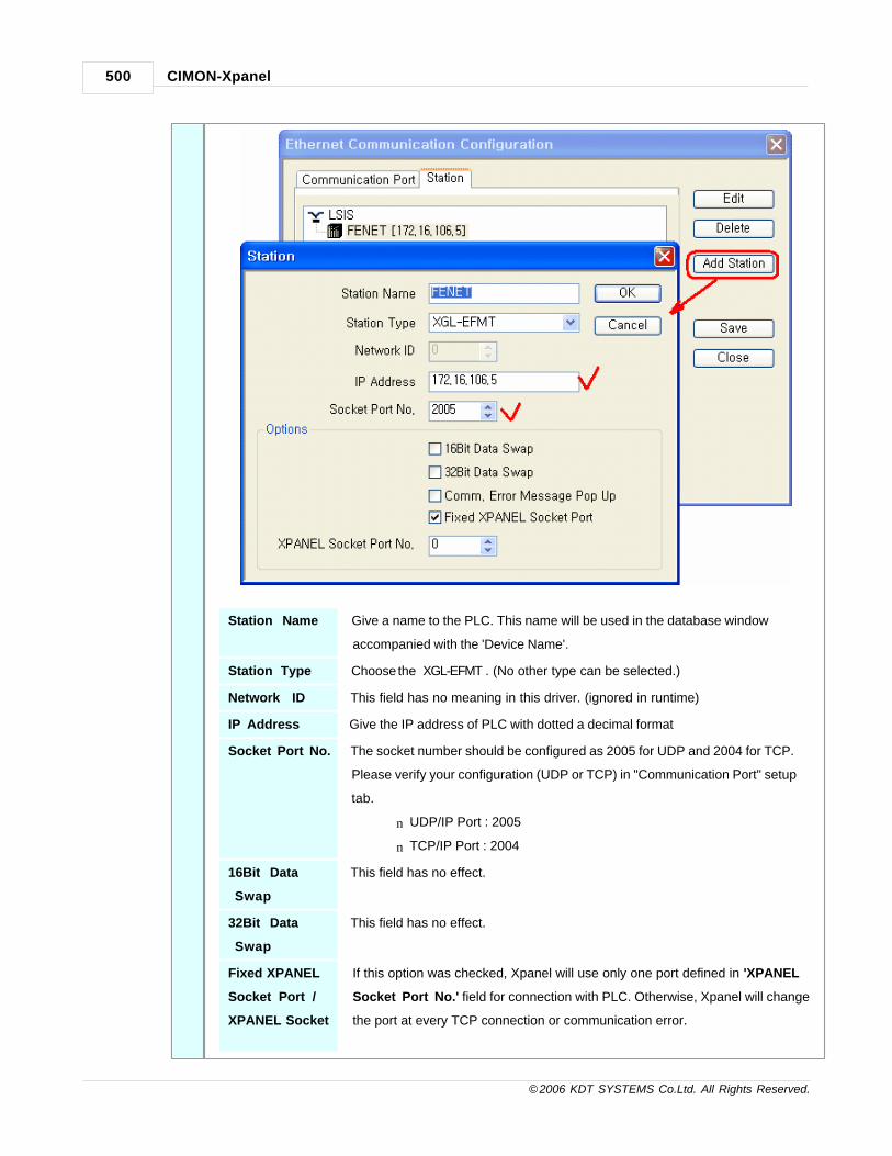
CIMON-Xpanel500
© 2006 KDT SYSTEMS Co.Ltd. All Rights Reserved.
Station Name Give a name to the PLC. This name will be used in the database window
accompanied with the 'Device Name'.
Station Type Choose the ‘XGL-EFMT’. (No other type can be selected.)
Network ID This field has no meaning in this driver. (ignored in runtime)
IP Address Give the IP address of PLC with dotted a decimal format
Socket Port No. The socket number should be configured as 2005 for UDP and 2004 for TCP.
Please verify your configuration (UDP or TCP) in "Communication Port" setup
tab.
n UDP/IP Port : 2005
n TCP/IP Port : 2004
16Bit Data
Swap
This field has no effect.
32Bit Data
Swap
This field has no effect.
Fixed XPANEL
Socket Port /
XPANEL Socket
If this option was checked, Xpanel will use only one port defined in 'XPANEL
Socket Port No.' field for connection with PLC. Otherwise, Xpanel will change
the port at every TCP connection or communication error.

Communication Driver 501
© 2006 KDT SYSTEMS Co.Ltd. All Rights Reserved.
Port No. This option is provided for Xpanel to deal with various TCP port management
ways of PLC. Some PLC has a limit on the number of TCP services. In that
case, this option can be a help.
The actual effect of this option on PLC cannot be described here. Because,
there are too many kinds of PLC and the response in PLC is entirely dependant
on the specification of PLC and engineer's experience.
The default setting of this option is unchecked state.
Comm. Error
Message Pop
Up
If this item is checked, Xpanel displays a communication error notification
message at every Rx and Tx error.
Otherwise(unchecked), Xpanel does not display the message at data receive
error. Only when there is data transmit (writing a TAG value to the station)
error, the notification message is popped up. This message box will be closed
automatically about 5 seconds after.
Communication Setup : XG5000
Following picture shows the screen shot of 'Network Manager' of XG5000 programming tool.
This window can be activated by the menu of 'Tool-Network Manager'.

CIMON-Xpanel502
© 2006 KDT SYSTEMS Co.Ltd. All Rights Reserved.
IP Address Give the IP address of PLC with dotted decimal format. This address has to beregistered in the device configuration of XPanelDesigner as described before.
Subnet mask,Gateway
Give the appropriate values which are provided by network administrator of your
system.
DHCP Do not use this option. The XPanel supports fixed IP address device only.
Driver Choose the “XGT server”.
Address Notation
The address of TAG in XPanel has the following format.
TAG Type Format Example
Analog [Symbol][Address] D064

Communication Driver 503
© 2006 KDT SYSTEMS Co.Ltd. All Rights Reserved.
Digital [Symbol][Address].[Bit Number] or [Symbol][Address][BitNumber]
M012.A or M012A
· Address : decimal number (0..65535)
· Bit Number : hexa-decimal number (0..F)
Following table shows the list of devices which can be referenced in XPanel database.
Symbol Description Range(Word)
WordNotation
BitNotation
Type Access
P I/O Relay 2048 P123 P123A Bit/Word R/W
M Auxiliary Relay 2048 M123 M123A Bit/Word R/W
L Link Relay 11264 L123 L123A Bit/Word R/W
K Keep Relay 8192 K123 K123A Bit/Word R/W
F Special Relay 2048 F123 F123A Bit/Word R
T Timer (CV) 2048 T123 - Word R/W
C Counter (CV) 2048 C123 - Word R/W
D Data Reg 32768 D123 D123.A(1) Bit/Word R/W
N Comm. DataReg
28763 N123 N123.A(1) Bit/Word R/W
(1) When a ‘D’ or ‘N’ register was referenced by a digital TAG with bit notation, it cannot be
written. (Read only)
Support Function Table
Following table shows the list of functions that are supported by ‘LSIS XGT Series Ethernet’
communication driver.
Function Support Remark
Block Data Read O
Block Data Write O
String real Tag O
Word Swap X
Dword Swap X

CIMON-Xpanel504
© 2006 KDT SYSTEMS Co.Ltd. All Rights Reserved.
Block DataRead
This function makes it possible that is bulk data reading at a time. It will be applied when you use recipe, data bridge and trends at theXpanel.
Block DataWrite
This function makes it possible that is bulk data writing at a time. It will be applied when you use recipe, data bridge and trends at theXpanel.
String real Tag It makes the device as the serialized memory so you can communicatestring data ofXpanel with PLC.
Word Swap This function swaps bytes of all word or double word sized data. Itdepends upon 16BitData Swap configuration.
Dword Swap This function swaps words of all double word sized data. It depends upon32Bit Data Swapconfiguration.
27.18 LSIS Master-K S Series PLC Loader
This driver provides the software interface and communication protocol between XPanel and LSIS Master-
K S Series Loader.
Communication Setup : Xpanel
Createanewdevice
For creating a new device activate the menu ‘Tools’- >’I/O Devices’ or icon in tool-bar.
Following picture shows the first step of creating a new device.

Communication Driver 505
© 2006 KDT SYSTEMS Co.Ltd. All Rights Reserved.
I/O Device Name
Give a device name. This name will be used in the TAG configuration window of database accompanied by the
‘Station Name’.
Selectadevicetype
Select a device type : LSIS Master-K H-Series PLC Loader
After selecting the ‘OK’ button of previous step, ‘Serial Communication Configuration’ dialog box will be
popped up as shown in following picture.

CIMON-Xpanel506
© 2006 KDT SYSTEMS Co.Ltd. All Rights Reserved.
In this window, select the ‘Device Type’ as ‘LSIS Master-K S-Series PLC Loader’ and appropriate
communication parameters. Ensure that those parameters are matched with the device’s configuration.
Createastation
Move to the ‘Station’ tab of ‘Serial Communication Configuration’ dialog box. In this dialog box, all the
connected PLC stations can be configured and registered to the XPanel. Each field can be configured with
following rules.

Communication Driver 507
© 2006 KDT SYSTEMS Co.Ltd. All Rights Reserved.
Station NameGive a name to the PLC. This name will be used in the database window accompanied
with the ‘Device Name’.
Station Type Choose the ‘S Series’. (Another type can’t be selected.)
Network ID This field has no meaning in this driver. (Ignored in runtime)
Station No. This number must be matched with the one of PLC.
16Bit Data Swap This field has no meaning in this driver.

CIMON-Xpanel508
© 2006 KDT SYSTEMS Co.Ltd. All Rights Reserved.
32Bit Data Swap This field has no meaning in this driver.
CheckSum This field has no meaning in this driver.
Comm. Error
Message Pop Up
If this item is checked, XPanel displays a communication error notification message at
every Rx and Tx error.
Otherwise(unchecked), XPanel does not display the message at data receive error.
Only when there is data transmit (writing a TAG value to the station) error, the
notification message is popped up. This message box will be closed automatically
about 5 seconds after.
Address Notation
Symbol Range Size Access
P P0 - P63F 64 R/W
M M0 - M203F 192 R/W
L L0 - L63F 64 R/W
K K0 - K31F 32 R/W
F F0 - F63F 64 R
T T0 - T256 256 R/W
C C0 -C256 256 R/W
D D0 -D9999 10000 R/W
S S0 - S99 100 R/W
Refer the upper table for available device range.
If you use ‘P,M,L,K,F’ device by digital tag, the lowest position number is hexadecimal and else
number decimal.
If you use ‘P,M,L,K,F’ device by analog tag, all number is decimal.
Communication Cable Wiring

Communication Driver 509
© 2006 KDT SYSTEMS Co.Ltd. All Rights Reserved.
RS-232C wiring
27.19 LSIS Master-K S Series PLC Cnet
This driver provides the software interface and communication protocol between XPanel and LSIS Master-
K H Series through RS232 or RS422/485.
Communication Setup : Xpanel
Createanewdevice
For creating a new device activate the menu ‘Tools’- >’I/O Devices’ or icon in tool-bar.
Following picture shows the first step of creating a new device.

CIMON-Xpanel510
© 2006 KDT SYSTEMS Co.Ltd. All Rights Reserved.
I/O Device Name
Give a device name. This name will be used in the TAG configuration window of database accompanied by
the ‘Station Name’.
Selectadevicetype
Select a device type : LSIS Master-K S-Series PLC Cnet
After selecting the ‘OK’ button of previous step, ‘Serial Communication Configuration’ dialog box will be
popped up as shown in following picture.

Communication Driver 511
© 2006 KDT SYSTEMS Co.Ltd. All Rights Reserved.
In this window, select the ‘Device Type’ as ‘LSIS Master-K S-Series PLC Cnet’ and appropriate
communication parameters. Ensure that those parameters are matched with the device’s configuration.
Createastation
Move to the ‘Station’ tab of ‘Serial Communication Configuration’ dialog box. In this dialog box, all the
connected PLC stations can be configured and registered to the XPanel. Each field can be configured with
following rules.

CIMON-Xpanel512
© 2006 KDT SYSTEMS Co.Ltd. All Rights Reserved.
Station NameGive a name to the PLC. This name will be used in the database window
accompanied with the ‘Device Name’.
Station Type Choose the ‘S Series’. (Another type can’t be selected.)
Network ID This field has no meaning in this driver. (Ignored in runtime)
Station No. This number must be matched with the one of PLC.
16Bit Data Swap This field has no meaning in this driver.

Communication Driver 513
© 2006 KDT SYSTEMS Co.Ltd. All Rights Reserved.
32Bit Data Swap This field has no meaning in this driver.
CheckSum This field has no meaning in this driver.
Comm. Error
Message Pop Up
If this item is checked, XPanel displays a communication error notification message at
every Rx and Tx error.
Otherwise(unchecked), XPanel does not display the message at data receive error.
Only when there is data transmit (writing a TAG value to the station) error, the
notification message is popped up. This message box will be closed automatically
about 5 seconds after.
Communication Setup : Frame Editor
Configure communication card setting by LSIS Cnet Frame Editor.
Option -> Port : Select proper PC’s port to connect loader.

CIMON-Xpanel514
© 2006 KDT SYSTEMS Co.Ltd. All Rights Reserved.
Online -> Connect
Online -> Read : Read configurations from communication card.
Onlie -> Write : Change the configurations for communication and download changed configurations.
Refer the manual for more details.
Address Notation
Symbol Range Size Access
P P0 - P63F 64 R/W
M M0 - M203F 192 R/W
L L0 - L63F 64 R/W
K K0 - K31F 32 R/W
F F0 - F63F 64 R
T T0 - T256 256 R/W
C C0 -C256 256 R/W
D D0 -D9999 10000 R/W
S S0 - S99 100 R/W
Refer the upper table for available device range.
If you use ‘P,M,L,K,F’ device by digital tag, the lowest position number is hexadecimal and
else number decimal.
If you use ‘P,M,L,K,F’ device by analog tag, all number is decimal.
Communication Cable Wiring
RS-232C wiring

Communication Driver 515
© 2006 KDT SYSTEMS Co.Ltd. All Rights Reserved.
RS-422 wiring
Use terminal resistance by 330Ω.
For stable communication, connect SG and use STP cable and surely earth the
shield.
RS-485 wiring
Use terminal resistance by 120Ω.
If you use RS-485, don’t connect RDA & RDB but SDA & SDB at Xpanel.
For stable communication, connect SG and use STP cable and surely earth the
shield.
27.20 LSIS Master-K H Series PLC Cnet
This driver provides the software interface and communication protocol between XPanel and LSIS Master-
K H Series through RS232 or RS422/485.
Communication Setup : Xpanel

CIMON-Xpanel516
© 2006 KDT SYSTEMS Co.Ltd. All Rights Reserved.
Createanewdevice
For creating a new device activate the menu ‘Tools’- >’I/O Devices’ or icon in tool-bar.
Following picture shows the first step of creating a new device.
I/O Device Name
Give a device name. This name will be used in the TAG configuration window of database accompanied by
the ‘Station Name’.
Selectadevicetype
Select a device type : LSIS Master-K H-Series PLC Cnet
After selecting the ‘OK’ button of previous step, ‘Serial Communication Configuration’ dialog box will be
popped up as shown in following picture.
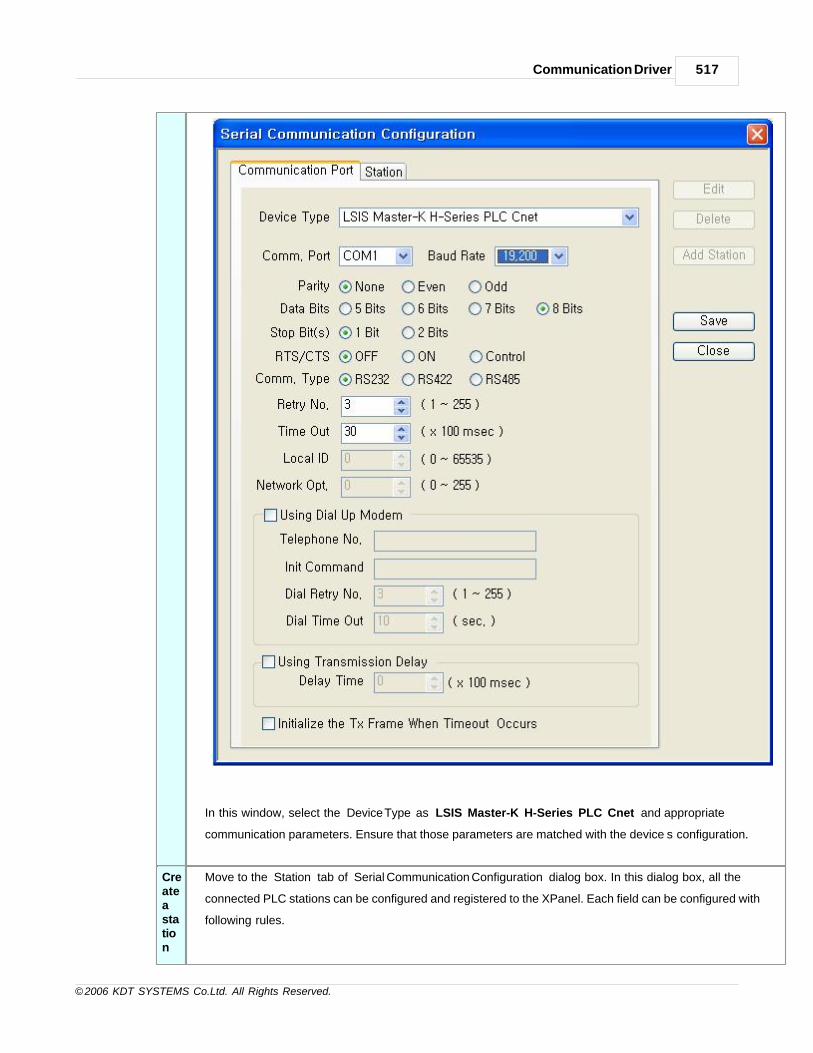
Communication Driver 517
© 2006 KDT SYSTEMS Co.Ltd. All Rights Reserved.
In this window, select the ‘Device Type’ as ‘LSIS Master-K H-Series PLC Cnet’ and appropriate
communication parameters. Ensure that those parameters are matched with the device’s configuration.
Createastation
Move to the ‘Station’ tab of ‘Serial Communication Configuration’ dialog box. In this dialog box, all the
connected PLC stations can be configured and registered to the XPanel. Each field can be configured with
following rules.

CIMON-Xpanel518
© 2006 KDT SYSTEMS Co.Ltd. All Rights Reserved.
Station NameGive a name to the PLC. This name will be used in the database window
accompanied with the ‘Device Name’.
Station Type Choose the ‘Master-K 500/1000’’. (Another type can’t be selected.)
Network ID This field has no meaning in this driver. (Ignored in runtime)
Station No. This number must be matched with the one of PLC.
16Bit Data Swap This field has no meaning in this driver.

Communication Driver 519
© 2006 KDT SYSTEMS Co.Ltd. All Rights Reserved.
32Bit Data Swap This field has no meaning in this driver.
CheckSum This field has no meaning in this driver.
Comm. Error
Message Pop Up
If this item is checked, XPanel displays a communication error notification message
at every Rx and Tx error.
Otherwise(unchecked), XPanel does not display the message at data receive error.
Only when there is data transmit (writing a TAG value to the station) error, the
notification message is popped up. This message box will be closed automatically
about 5 seconds after.
Master-K 500/1000 DIP SWITCH Configuration
*If communication type is RS-485, configure baud rate by loader.
Address Notation
Symbol Range Size Access
P P0 - P63F 64 R/W

CIMON-Xpanel520
© 2006 KDT SYSTEMS Co.Ltd. All Rights Reserved.
M M0 - M203F 192 R/W
L L0 - L63F 64 R/W
K K0 - K31F 32 R/W
F F0 - F63F 64 R
T T0 - T256 256 R/W
C C0 -C256 256 R/W
D D0 -D9999 10000 R/W
S S0 - S99 100 R/W
Refer the upper table for available device range.
If you use ‘P,M,L,K,F’ device by digital tag, the lowest position number is hexadecimal and
else number decimal.
If you use ‘P,M,L,K,F’ device by analog tag, all number is decimal.
Communication Cable Wiring
RS-232C wiring

Communication Driver 521
© 2006 KDT SYSTEMS Co.Ltd. All Rights Reserved.
RS-422 wiring
Use terminal resistance by 330Ω.
For stable communication, connect SG and use STP cable and surely earth the
shield.
RS-485 wiring
Use terminal resistance by 120Ω.
If you use RS-485, don’t connect RDA & RDB but SDA & SDB at Xpanel.
For stable communication, connect SG and use STP cable and surely earth the
shield.
27.21 LSIS Master-K S Series PLC Enet
This driver provides the software interface and communication protocol between XPanel and CIMON-
PLC.
Following module is able to communicate with this driver.
Communication Setup : Xpanel
Createanewdevice
For creating a new device activate the menu ‘Tools’- >’I/O Devices’ or icon in tool-bar.
Following picture shows the first step of creating a new device.

CIMON-Xpanel522
© 2006 KDT SYSTEMS Co.Ltd. All Rights Reserved.
I/O Device Name
Give a device name. This name will be used in the TAG configuration window of database accompanied by the
‘Station Name’.
Selectadevicetype
Select a device type : LSIS Master-K S-Series PLC Ethernet
After selecting the ‘OK’ button of previous step, ‘Serial Communication Configuration’ dialog box will be
popped up as shown in following picture.
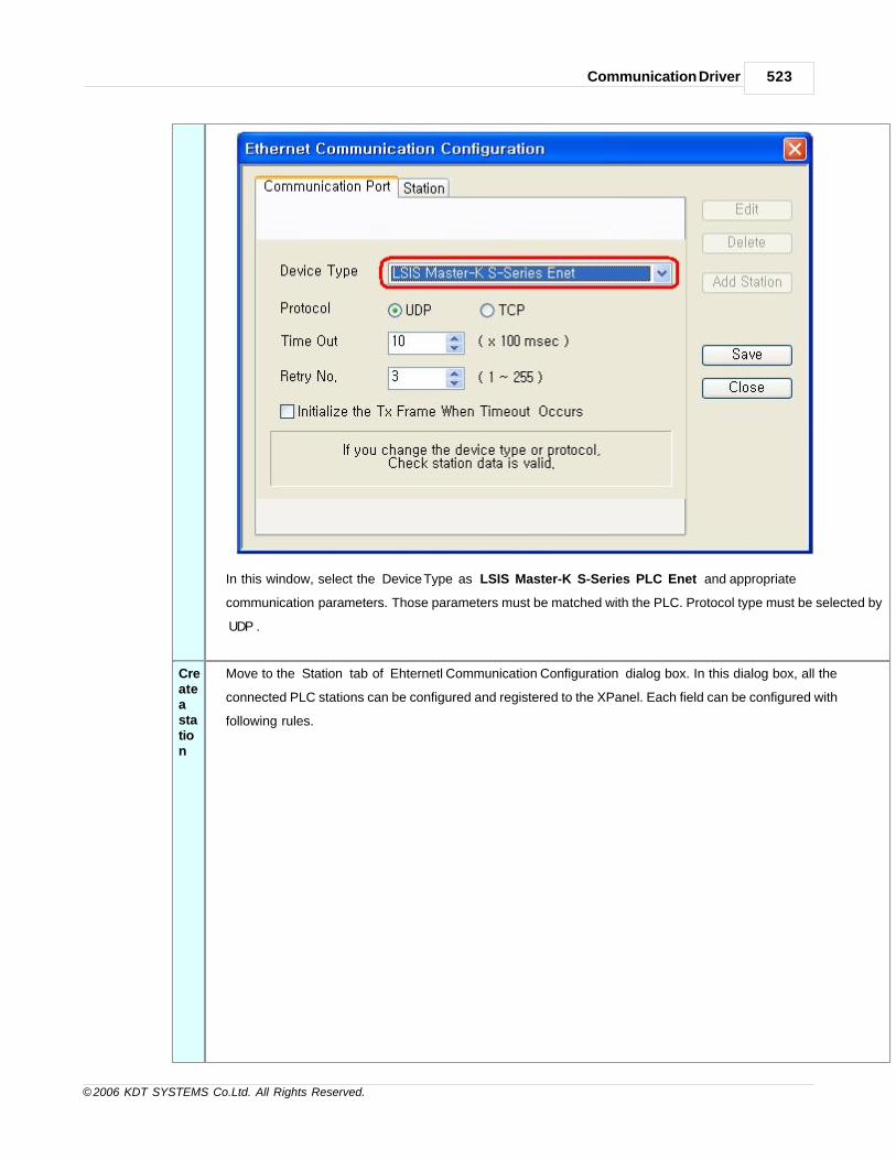
Communication Driver 523
© 2006 KDT SYSTEMS Co.Ltd. All Rights Reserved.
In this window, select the ‘Device Type’ as ‘LSIS Master-K S-Series PLC Enet’ and appropriate
communication parameters. Those parameters must be matched with the PLC. Protocol type must be selected by
‘UDP’.
Createastation
Move to the ‘Station’ tab of ‘Ehternetl Communication Configuration’ dialog box. In this dialog box, all the
connected PLC stations can be configured and registered to the XPanel. Each field can be configured with
following rules.

CIMON-Xpanel524
© 2006 KDT SYSTEMS Co.Ltd. All Rights Reserved.
Station NameGive a name to the PLC. This name will be used in the database window accompanied
with the ‘Device Name’.
Station Type Choose the ‘Master-K S ’. (You can’t select any other type.)
Network ID This field has no meaning in this driver. (Ignored in runtime)
IP Address Input PLC’s IP by decimal number and point for connection.
Socket Port No. If you want to use UDP, port number is 2005 else TCP, port number is 2004.
Go to “Communication Port” and confirm the protocol. (UDP or TCP)
16Bit Data Swap This field has no meaning in this driver.
32Bit Data Swap This field has no meaning in this driver.
Fixed XPANEL
Socket Port
If you select this option, XPanel use only one port to connect PLC defined by ‘Xpanel
Socket Port No.’ If it is not, Xpanel will change the port no. when it occurs
communication error.
This option makes XPanel to handle various port management methods. Several PLC has
restriction about TCP service number. In that case, this option will help.

Communication Driver 525
© 2006 KDT SYSTEMS Co.Ltd. All Rights Reserved.
We can’t mention all about this option this time. Because, too many PLC beings this
world and response of PLC totally depended from PLC manual and engineer’s
experience.
This option is unchecked by default.
Comm. Error
Message Pop Up
If this item is checked, XPanel displays a communication error notification message at
every Rx and Tx error.
Otherwise(unchecked), XPanel does not display the message at data receive error. Only
when there is data transmit (writing a TAG value to the station) error, the notification
message is popped up. This message box will be closed automatically about 5 seconds
after.
Communication Setup : Frame Editor
Following picture shows frame editor for configure of Master K Ethernet module.

CIMON-Xpanel526
© 2006 KDT SYSTEMS Co.Ltd. All Rights Reserved.
Edit -> Basic Parameters

Communication Driver 527
© 2006 KDT SYSTEMS Co.Ltd. All Rights Reserved.
IP AddressInput PLC’s IP address by decimal number and point. It is must be same previous
set at XPanelDesigner’s I/O device configuration.
Subnet Mask, Gateway
Input the proper value offered from system network manager.
Input same value with Xpanel.
DNS Server Input the proper value offered from system network manager.
Address Notation
Following table shows address notation at XPanel.
TYPE FORM Example
Analog [Symbol][Address] D064
Digital[Symbol][Address].[Bit Number] or [Symbol][Address][Bit Number]
M012.A or M012A
· Address : Decimal (0..65535)

CIMON-Xpanel528
© 2006 KDT SYSTEMS Co.Ltd. All Rights Reserved.
· Bit Number : Hex (0..F)
Following table shows referable device list by XPanel.
Symbol Description Range
(word)
Word
Notation
Bit
Notation
Type Read Write
P I/O Relay 1024 P23 P23A Bit/Word R/W
M Auxiliary Relay 3072 M23 M23A Bit/Word R/W
L Link Relay 1024 L23 L23A Bit/Word R/W
K Keep Relay 512 K23 K23A Bit/Word R/W
F Special Relay 1024 F23 F23A Bit/Word R
T Timer (CV) 256 T123 - Word R/W
C Counter (CV) 256 C123 - Word R/W
D Data Reg 10000 D123 D123.A(1) Bit/Word R/W
S Special Reg. 100 S123 S123.A(1) Bit/Word R/W
(1) If register as ‘D’ or ‘S’ is used by BIT, it can’t use write but only read.
Support Function Table
Next table shows the available functions from the ‘LSIS Master-K S-Series Enet’ communication driver.
Function Support Remark
Block Data Read O
Block Data Write O
String real Tag O
Word Swap X
Dword Swap X
Block DataRead
This function makes it possible that is bulk data reading at a time. It will be
applied when you use recipe, data bridge and trends at the Xpanel.
Block DataWrite
This function makes it possible that is bulk data writing at a time. It will be applied
when you use recipe, data bridge and trends at the Xpanel.
String real TagIt makes the device as the serialized memory so you can communicate string
data of Xpanel with PLC.
Word Swap This function swaps bytes of all word or double word sized data. It depends upon

Communication Driver 529
© 2006 KDT SYSTEMS Co.Ltd. All Rights Reserved.
16Bit Data Swap configuration.
Dword SwapThis function swaps words of all double word sized data. It depends upon 32Bit
Data Swap configuration.
27.22 LSIS Inverter Starvert
This driver can communicate with iP5A and iV5 inverters from LSIS via its dedicated protocol.
Communication Setup : (iP5A example)
For normal communication, following parameter must be set as noted at inverter side.
[Inverter Setting Example]
Parameter
NumberSet Value Description
DRV_03 Int. 485 Drive mode
DRV_04 Int. 485 Frequency control mode
I/O_90 1 Station number (1 .. 250)
I/O_91 9600 Communication speed (19200, 9600 or 4800 recommended)
Communication Setup : Xpanel
Createa newDevice
For creating a new device activate the menu ‘Tools’- >’I/O Devices’ or icon in tool-bar.
Following picture shows the first step of creating a new device.

CIMON-Xpanel530
© 2006 KDT SYSTEMS Co.Ltd. All Rights Reserved.
I/O Device Name : Give a device name. This name will be used in the TAG configuration window of
database
accompanied by the ‘Station Name’.
Selectadevicetype
I/O Device type : ' LSIS INVERTER Starvert Series '
After selecting the ‘OK’ button of previous step, ‘Serial Communication Configuration’ dialog box will be
popped up as
shown in following picture.
In this window, select the ‘Device Type’ as ‘LSIS INVERTER Starvert Series’ and configure the proper serial
communication parameters. Ensure that those parameters are matched with the inverter configuration.
All communication parameters except baudrate are fixed as : no parity, 8 data bits, 1 stop bit.

Communication Driver 531
© 2006 KDT SYSTEMS Co.Ltd. All Rights Reserved.
Createastation
Move to the ‘Station’ tab of ‘Serial Communication Configuration’ dialog box.
In this dialog box, all the connected inverter stations can be configured and registered to the XPanel.
Each field can be configured with following rules.

CIMON-Xpanel532
© 2006 KDT SYSTEMS Co.Ltd. All Rights Reserved.
Station Name Give a name to the PLC.
This name will be used in the database window accompanied with the ‘Device
Name’.
Station Type Choose one of two inverter models (‘iP5A’ and ‘iV5’) .
Network ID This field has no meaning in this driver.
Station No Specify a decimal number between 1 and 250.
16Bit Data
Swap
This field has no effect.
32Bit Data
Swap
This field has no effect.
Using
Checksu
m
This field has no effect.
Comm. Error
Message pop
Up
If this item is checked, Xpanel displays a communication error notification message
at every Rx and Tx error.Otherwise(unchecked), Xpanel does not display the
message at data receive error. Only when there is data transmit (writing a TAG value

Communication Driver 533
© 2006 KDT SYSTEMS Co.Ltd. All Rights Reserved.
to the station) error, the notification message is popped up. This message box will
be closed automatically about 5 seconds after.
Address Notation
The address of TAG in XPanel has the following format.
TAG Type Format Example
Analog [Symbol][Hexadecimal Number] M0006
Digital [Symbol][Hexadecimal Number][.][Decimal Number] M0006.12
Symbol Address Description
M 0000 002C Communication Memory Area
R 0500 051B Reference Data Memory Area (Not supported in iP5A model)
P 9100 - 9800 Parameter Memory Area
Above addresses can be used in both of analog and digital TAG.
For more information of each point, please refer to the manual of inverter.
Communication Cable Wiring
27.23 MITSUBISHI Inverter FR-E500
This driver can communicate with the FR-E510/520/540 inverter series from Mitsubishi.

CIMON-Xpanel534
© 2006 KDT SYSTEMS Co.Ltd. All Rights Reserved.
Xpanel Setting Example
For normal communication, following parameter must be set as noted at inverter side.
· CR/LF instruction presence/absence (Pr. 124) : Mode 2 (with CR/LF)
· Comm. response waiting time (Pr. 123) : 9999 (use the waiting time data)
Inverter Setting Example
Parameter Number Set Value Description
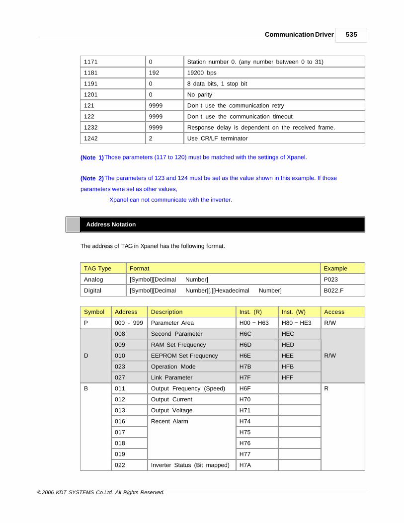
Communication Driver 535
© 2006 KDT SYSTEMS Co.Ltd. All Rights Reserved.
1171 0 Station number 0. (any number between 0 to 31)
1181 192 19200 bps
1191 0 8 data bits, 1 stop bit
1201 0 No parity
121 9999 Don’t use the communication retry
122 9999 Don’t use the communication timeout
1232 9999 Response delay is dependent on the received frame.
1242 2 Use CR/LF terminator
(Note 1) Those parameters (117 to 120) must be matched with the settings of Xpanel.
(Note 2) The parameters of 123 and 124 must be set as the value shown in this example. If those
parameters were set as other values,
Xpanel can not communicate with the inverter.
Address Notation
The address of TAG in Xpanel has the following format.
TAG Type Format Example
Analog [Symbol][Decimal Number] P023
Digital [Symbol][Decimal Number][.][Hexadecimal Number] B022.F
Symbol Address Description Inst. (R) Inst. (W) Access
P 000 - 999 Parameter Area H00 H63 H80 HE3 R/W
D
008 Second Parameter H6C HEC
R/W
009 RAM Set Frequency H6D HED
010 EEPROM Set Frequency H6E HEE
023 Operation Mode H7B HFB
027 Link Parameter H7F HFF
B 011 Output Frequency (Speed) H6F R
012 Output Current H70
013 Output Voltage H71
016 Recent Alarm H74
017 H75
018 H76
019 H77
022 Inverter Status (Bit mapped) H7A

CIMON-Xpanel536
© 2006 KDT SYSTEMS Co.Ltd. All Rights Reserved.
C
016 Alarm Definition Batch Clear HF4
W022 Run Command (Bit mapped) HFA
024 All Parameter Clear HFC
025 Inverter Reset HFD
Above addresses can be used in both of analog and digital TAG.
For more information of each point, please refer to the manual of inverter.
Communication Cable Wiring
27.24 MITSUBISHI Melsec 1C (ACPU, AnA/AnU CPU)
This Manual explains about the method of CIMON-Xpanel using ‘MITSUBISHI Melsec 1C protocol’

Communication Driver 537
© 2006 KDT SYSTEMS Co.Ltd. All Rights Reserved.
communication with
ACPU, AnA/AnU CPU using RS232C or RS422/485.
Communication Setup : Xpanel
You can configure I/O device according to various kind of field equipments by using Xpanel Designer.
Configure the option of the example followed. More details about I/O device configuration in section “I/O
device configuration”.
Create a newDevice
To configure the communication device of Melsec 1C (ACPU, AnA/AnU CPU) PLC, Select
'Tools - I/O device' in the
menu or icon in tool-bar, and then “I/O device configuration” dialog box will be shown up.
And then click [new device] button. “I/O device selection” dialog box is shown up, select a
device name and a device type as the following figure.
I/O Device Name MEL
In the case there are various kinds of field equipments, Type device

CIMON-Xpanel538
© 2006 KDT SYSTEMS Co.Ltd. All Rights Reserved.
name to identify what equipments it is. The string “MEL” of this item will
be shown up in the selection list of I/O device when you register a tag.
Xpanel can communicate with various kinds of equipment
simultaneously connected by identifying equipment by its name. The
value which is saved as a tag is the compound string of a device name
and station name as following “MEL.ST” (“DEV” is a device name, and
“ST" is a station name). And it is used as a unique identifier in Xpanel
project.
I/O Device
Selection
Serial device
You can select field equipment and a communication type. Select one
according to the communication method of the selected device.
Select a devicetype
I/O Device type : ' MITSUBISHI Melsec 1C (AnA/AnU CPU) '
You can select communication device which is connected to Xpanel. This example shows you
selecting “MITSUBISHI Melsec 1C (AnA/AnU CPU)”. But if you want to use ACPU, select
“MITSUBISHI 1C (ACPU).

Communication Driver 539
© 2006 KDT SYSTEMS Co.Ltd. All Rights Reserved.
Comm.Port COM1
This example uses COM1 port. If you want use other ports, select one in
the combo box.
Baud rate 19,200
Select the communication speed to equipment. The configuration of the
communication speed of Xpanel must be the same as the configuration of
equipment. If speed of the configurations of two sides are not same, they

CIMON-Xpanel540
© 2006 KDT SYSTEMS Co.Ltd. All Rights Reserved.
will not be communicated each other.
Parity None
Data bits 8 Bits
Stop bits 1 Bits
RTS/CTS ON
This example uses RTS-CTS control always ON doing.
Comm. Type RS232
This example selects S232 communication.
When you use RS-422 communication select RS-422 or you use RS-485
communication then select RS-485.
Retry No. 3
If communication failed with the kind of field equipments, it will retry as
the number of this.
Time Out 30
If you input as the number of 30 then it’s time out count will be 30
seconds.
Using Dial Up
Modem
Not Select
This item can be chosen only when you use Dial Up modem.
Create a station Move to [Station] tab at the “Serial Communication Configuration” Dialog Box and click [Add
Station] button
then you can see “Station” Dialog Box popped up. Please configuration as the following
contents then click “OK” button.

Communication Driver 541
© 2006 KDT SYSTEMS Co.Ltd. All Rights Reserved.
Station Name ST
When field equipments number exceed over than 2, station name is used
for division of field equipment at the internal Xpanel.
Internal Xpanel it expresses as “Device.Station” and this example shows
you as “DEV.ST” .
Station Type AnA / AnU
Network ID This field has no effect.
Station No. 0
When field equipments number exceed over than 2, it assigned different
Station No. to divide. Station number must be same configured in field
equipments. It will not be communicated if the Station No. different each
other.
Socket Port
No.
2005
The exclusive use of GLOFA Enet supporting socket number is TCP 2004,
UDP 2005.
16Bit Data
Swap
This field has no effect.
32Bit Data
Swap
This field has no effect.
Using
Checksum
This field has no effect.
Comm. Error
Message Pop
Up
If this item is checked, Xpanel displays a communication error notification
message at every Rx and Tx error.
Otherwise(unchecked), Xpanel does not display the message at data
receive error. Only when there is data transmit (writing a TAG value to the
station) error, the notification message is popped up. This message box
will be closed automatically about 5 seconds after.
Configuration of PLC Communication module : AJ71UC24
According to the following explain, configure communication module. If you want more details or not
included contents in this manual,
refer to module manuals.
ModeConfiguration
Xpanel communicate with PLC using “A compatible 1C Frame”. You can choose one of
the protocols using Mode setting switch. If you use RS-232, configure the switch as 1

CIMON-Xpanel542
© 2006 KDT SYSTEMS Co.Ltd. All Rights Reserved.
Switch or you use RS-422/485 configure the switch as 5.
When RS-232 and RS-422/485 is used at the same time, configure switch as A.
Station No.ConfigurationSwitch
Station number must same of Xpanel Station No. Above configuration of the Xpanel
station number is 0.
Both x10 and x1, configure as 0.
CommunicationConfigurationSwitch
Communication configuration switch configure as the following figure.
switch
configuration Configure state
OFF ON
SW11
Main channel RS-232C RS-422
SW12
Data Bit 7 Bit 8 Bit
SW13
Baud rate Refer to the follows
SW14
SW15
SW16
Parity Using OFF ON
SW17
Even/Odd Parity Odd Even
SW18
Stop Bit 1 Bit 2 Bit
SW21
Sum check 사용 OFF ON
SW22
RUN중 Write 가능 impossible possible
SW23
Computer Link /
Multi-drop Link
Multi-drop ComputerLink
SW24
수신 측 종단 저항 Not being Being
Baud rate configuration
Baud rate(bps)
300 600 1200 2400 4800 9600 19200
SW13 OFF ON OFF ON OFF ON OFF
SW14 OFF OFF ON ON OFF OFF ON
SW15 OFF OFF OFF ON ON ON ON
If all configurations were ended, reboot the PLC and then apply changed
configurations.

Communication Driver 543
© 2006 KDT SYSTEMS Co.Ltd. All Rights Reserved.
Wiring Diagram
You can wire communication cable as the following figures.
RS-232C
RS-422
On wiring as the above figure terminal resistance must be 330Ω.
To improve stability of communication it should connect SG and use STP cable. But
shielded cables must be earthed.
RS-485
On wiring as the above figure terminal resistance must be 120Ω.
When Xpanel is using RS-485, it connects with SDA and SDB but disconnect with

CIMON-Xpanel544
© 2006 KDT SYSTEMS Co.Ltd. All Rights Reserved.
RDA and RDB.
To improve stability of communication it should connect SG and use STP cable.
But shielded cables must be earthed.
Device Memory range
Device SymbolI/O Device
Type Bit/WordMelsec 1C (ACPU) Melsec 1C (AnA/AnU)
Input X X0000-X07FF X000000-X001FFF Hex Bit
Output Y Y0000-Y07FF Y000000-Y001FFF Hex Bit
Internal Relay M M0000-M2047 M000000-M008191 Decimal Bit
Latch Relay L L0000-L2047 M000000-M008191 Decimal Bit
Step Relay S S0000-S2047 S000000-S008191 Decimal Bit
Link Relay B B0000-B03FF B000000-B001FFF Hex Bit
annanciator F F0000-M0255 F000000-F002047 Decimal Bit
special Relay M M9000-M9255 M009000-M009255 Decimal Bit
special register D D9000-D9255 D9000-D9255 Decimal Word
Timer (point) T TS000-TS255 TS00000-TS02047 Decimal Word
Timer (coil) T TC000-TC255 TC00000-TC02047 Decimal Word
Timer(present value) T TN000-TN255 TN00000-TN02047 Decimal Word
counter (point) C CS000-CS255 CS00000-CS01023 Decimal Word
counter (coil) C CC000-CC255 CC00000-CC01023 Decimal Word
counter (present value) C CN000-CN255 CN00000-CN01023 Decimal Word
data register D D0000-D1023 D000000-D08191 Decimal Word
Link register W W0000-W03FF W000000-W001FFF Hex Word
File register R R0000-R8191 R000000-R008191 Decimal Word
Usable device ranges are described above figure. You must use device in the allowable range. Note that
Input(X) and output(Y) are Hexadecimal.
Error Code
When Xpanel communicates with PLC it can receive NAK including error code.

Communication Driver 545
© 2006 KDT SYSTEMS Co.Ltd. All Rights Reserved.
Reference Error code contents as following table.
ErrorCode
Error type Error contents Solution
00H Impossible on RUN Even if it is forbade writing on
Run, it receive writing commend
Change the configuration of On Run
writable.
01H Parity error Parity bit wrong Change the configuration of
Parity bit.
02H Sum-check error Uncorrected Sum-check Check the wiring of the communication
03H Protocol error Receiving uncorrected
statement that is violate control
order of the protocol.
Confirm the opponent equipment’s
transfer statement and communicate
after modifying.
04H Framing error Uncorrected stop-bit
configuration
Change the configuration of Stop-bit
05H Over-run error In the case of it receive data
before the previous data
receiving ended
Down the Baud rate and then try
communication again.
06H Character part error · Assignment method error of
statement
· In the case of receiving not
existed command
· In the case of exceeding
allowable range
· In the case of assigned not
existing device
Check the device range
07H Character error In the case of receiving data
which it cannot use
Confirm the opponent equipment’s
transfer statement and communicate
after modifying.
08H PLC access error Cannot communication CPU Substitute CPU as the useable
10H PLC number error PLC number is not “FF” or
configured station number of
network parameter.
Confirm the opponent equipment’s
transfer statement and communicate
after modifying.
11H Mode error Error detection with PLC CPU Substitute CPU as the useable
12H Special function
module assignment
error
Special function module is not
existed in assigned location.
Confirm the opponent equipment’s
transfer statement and communicate
after modifying.
21H Special function
module bus error
Access error to the special
module detected in assigned
According to the correspondent module
manual, detect error and solute the

CIMON-Xpanel546
© 2006 KDT SYSTEMS Co.Ltd. All Rights Reserved.
location problem as indicated.
27.25 MITSUBISHI Melsec 3E(Q/QnA)
This driver provides the software interface and communication protocol between Xpanel and Mitsubishi
MELSEC Q Series PLCs.
This protocol uses binary code. It supports the following families of MELSEC PLCs Ethernet modules.
· QJ71E71, QJ71E71-B2
Communication Setup : Xpanel
Create a newDevice For creating a new device activate the menu ‘Tools’- >’I/O Devices’ or icon in tool-bar.
Following picture shows the first step of creating a new device.
I/O Device Name : Give a device name. This name will be used in the TAG configuration window
of database
accompanied by the ‘Station Name’.
Select a devicetype
I/O Device type : MITSUBISHI Melsec 3E
After selecting the ‘OK’ button of previous step, ‘Ethernet Communication Configuration’
dialog box will be popped up as shown in following picture.

Communication Driver 547
© 2006 KDT SYSTEMS Co.Ltd. All Rights Reserved.
In this window, select the ‘Device Type’ as ‘MITSUBISHI MELSEC 3E’ and configure the proper
Ethernet
communication parameters.
Create a station Move to the ‘Station’ tab of ‘Ethernet Communication Configuration’ dialog box.
In this dialog box, all the connected PLC stations can be configured and registered to the Xpanel.
Each field can
be configured with following rules.

CIMON-Xpanel548
© 2006 KDT SYSTEMS Co.Ltd. All Rights Reserved.
Station Name Give a name to the PLC. This name will be used in the database window
accompanied with the ‘Device Name’.
Station Type Choose the ‘MELSEC’. (No other type can be selected.)
Network ID This field has no effect.
IP Address Give the IP address of PLC with dotted decimal format.
Socket Port
Number
Give the port number opened by the PLC.The default value of this field is
5000.
16Bit Data
Swap
This field has no effect.
32Bit Data
Swap
This field has no effect.
Comm. Error
Message Pop
Up
If this item is checked, Xpanel displays a communication error notification
message at every Rx and Tx error. Otherwise(unchecked), Xpanel does not
display the message at data receive error. Only when there is data transmit
(writing a TAG value to the station) error, the notification message is popped
up. This message box will be closed automatically about 5 seconds after.

Communication Driver 549
© 2006 KDT SYSTEMS Co.Ltd. All Rights Reserved.
Fixed XPANELSocketPort / XPANELSocketPort No.
If this option was checked, Xpanel will use only one port defined in ‘XPANEL
Socket Port No.” field for connection with PLC. Otherwise, Xpanel will change
the port at every TCP connection or communication error.
This option is provided for Xpanel to deal with various TCP port management
ways of PLC. Some PLC has a limit on the number of TCP services. In that
case, this option can be a help.
The actual effect of this option on PLC cannot be described here. Because,
there are too many kinds of PLC and the response in PLC is entirely
dependant on the specification of PLC and engineer’s experience.
The default setting of this option is unchecked state.
Address Notation
The address of TAG in Xpanel has the following format.
Type Format Example
10 [Symbol][Address in decimal number] D0012
16 [Symbol][Address in hexa-decimal number] X01FC
Following table shows the list of devices which can be referenced in Xpanel database.
Memory Area Symbol I/O Address Range Notation Bit/Word
Input Relay X X000000-X001FFF 16 Bit
Output Relay Y Y000000-Y001FFF 16 Bit
Internal Relay M M000000-M008191 10 Bit
M M009000-M009255 10 Bit
Latch Relay L L000000-L008191 10 Bit
Step Relay S S000000-S008191 10 Bit
Link Relay B B000000-B001FFF 16 Bit
Annunciator F F000000-F002047 10 Bit
Timer Contact TS TS00000-TS02047 10 Word
Timer Coil TC TC00000-TC02047 10 Word
Timer Current Value TN TN00000-TN02047 10 Word
Retentive Timer Contact SS SS00000-SS02047 10 Word
Retentive Timer Coil SC SC00000-SC02047 10 Word
Retentive Timer Current Value SN SN00000-SN02047 10 Word

CIMON-Xpanel550
© 2006 KDT SYSTEMS Co.Ltd. All Rights Reserved.
Counter Contact CS CS00000-CS01023 10 Word
Counter Coil CC CC00000-CC01023 10 Word
Counter Current Value CN CN00000-CN01023 10 Word
Data Register D D000000-D08191 10 Word
D D9000-D9255 10 Word
Link Register W W000000-W001FFF 16 Word
File Register R R000000-R008191 10 Word
Communication Cable Wiring
Connectthrough theEthernet HUB
Directconnection

Communication Driver 551
© 2006 KDT SYSTEMS Co.Ltd. All Rights Reserved.
27.26 MITSUBISHI Melsec 1E
This driver provides the software interface and communication protocol between XPanel and Mitsubishi
MELSEC A or Q Series PLCs.
This protocol uses binary code. It supports the following families of MELSEC PLCs Ethernet modules.
•AJ71E71
This communication module can be used to access data of ACPU.
•QJ71E71, QJ71E71-B2
These communication modules can be used to access data of QCPU and QnACPU.
Communication Setup : Xpanel
Create a newDevice For creating a new device activate the menu ‘Tools’- >’I/O Devices’ or icon in tool-bar.
Following picture shows the first step of creating a new device.

CIMON-Xpanel552
© 2006 KDT SYSTEMS Co.Ltd. All Rights Reserved.
I/O Device Name : Give a device name. This name will be used in the TAG configuration
window of database
accompanied by the ‘Station Name’.
Select a devicetype
I/O Device Type : MITSUBISHI Melsec 1E
After selecting the ‘OK’ button of previous step, ‘Ethernet Communication Configuration’
dialog box will be
popped up as shown in following picture.

Communication Driver 553
© 2006 KDT SYSTEMS Co.Ltd. All Rights Reserved.
In this window, select the ‘Device Type’ as ‘MITSUBISHI MELSEC 1E’ and configure the proper
Ethernet communication parameters.
Create a station Move to the ‘Station’ tab of ‘Ethernet Communication Configuration’ dialog box.
In this dialog box, all the connected PLC stations can be configured and registered to the
XPanel. Each field can be configured with following rules.

CIMON-Xpanel554
© 2006 KDT SYSTEMS Co.Ltd. All Rights Reserved.
Station Name Give a name to the PLC. This name will be used in the database window
accompanied
with the ‘Device Name’
Station Type MELSEC
Network ID This field has no effect.
IP Address Give the IP address of PLC with dotted decimal format.
Socket Port
Number
Give the port number opened by the PLC. The default value of this field
is 5000.
16Bit Data
Swap
This field has no effect.
32Bit Data
Swap
This field has no effect.
Comm. Error
Message Pop
Up
If this item is checked, XPanel displays a communication error
notification message at
every Rx and Tx error.
Otherwise(unchecked), XPanel does not display the message at data
receive error.
Only when there is data transmit

Communication Driver 555
© 2006 KDT SYSTEMS Co.Ltd. All Rights Reserved.
(writing a TAG value to the station) error, the notification message is
popped up.
This message box will be closed automatically about 5 seconds after.
Fixed XPANEL
Socket Port /
XPANEL Socket
Port No.
If this option was checked, XPanel will use only one port defined in ‘
XPANEL Socket
Port No.” field for connection with PLC.
Otherwise, XPanel will change the port at every TCP connection or
communication error.
This option is provided for XPanel to deal with various TCP port
management ways of
PLC. Some PLC has a limit on the number of TCP services. In that
case, this option can
be a help. The actual effect of this option on PLC cannot be described
here.
Because, there are too many kinds of PLC and the response in PLC is
entirely
dependant on the specification of PLC and engineer’s experience.
The default setting of this option is unchecked state.
Address Notation
The address of TAG in XPanel has the following format.
Type Format Example
10 [Symbol][Address in decimal number] D0012
16 [Symbol][Address in hexa-decimal number] X01FC
Following table shows the list of devices which can be referenced in XPanel database.
Memory Area Symbol I/O Address Range Notation Bit/Word
Input Relay X X000000-X001FFF 16 Bit
Output Relay Y Y000000-Y001FFF 16 Bit
Internal Relay M M000000-M008191 10 Bit
Link Relay B B000000-B001FFF 16 Bit

CIMON-Xpanel556
© 2006 KDT SYSTEMS Co.Ltd. All Rights Reserved.
Annunciator F F000000-F002047 10 Bit
Timer Contact TS TS00000-TS02047 10 Word
Timer Coil TC TC00000-TC02047 10 Word
Timer Current Value TN TN00000-TN02047 10 Word
Counter Contact CS CS00000-CS01023 10 Word
Counter Coil CC CC00000-CC01023 10 Word
Counter Current Value CN CN00000-CN01023 10 Word
Data Register D D000000-D12286 10 Word
Link Register W W000000-W001FFF 16 Word
File Register R R000000-R008191 10 Word
Communication Cable Wiring
Connectthrough theEthernet HUB
Directconnection

Communication Driver 557
© 2006 KDT SYSTEMS Co.Ltd. All Rights Reserved.
27.27 MITSUBISHI Melsec 3E ASCII
This driver provides the software interface and communication protocol between XPanel and Mitsubishi
MELSEC Q Series PLCs.
This protocol uses the ASCII code. It supports the following families of MELSEC PLCs Ethernet modules.
· QJ71E71, QJ71E71-B2
Communication Setup : Xpanel
Create a newDevice For creating a new device activate the menu ‘Tools’- >’I/O Devices’ or icon in tool-bar.
Following picture shows the first step of creating a new device.

CIMON-Xpanel558
© 2006 KDT SYSTEMS Co.Ltd. All Rights Reserved.
I/O Device Name : Give a device name. This name will be used in the TAG configuration window
of database
accompanied by the ‘Station Name’.
Select a devicetype
I/O Device type : MITSUBISHI Melsec 3E(ASCII)
After selecting the ‘OK’ button of previous step, ‘Ethernet Communication Configuration’
dialog box will be popped up as shown in following picture.

Communication Driver 559
© 2006 KDT SYSTEMS Co.Ltd. All Rights Reserved.
In this window, select the ‘Device Type’ as ‘MITSUBISHI MELSEC 3E (ASCII)’ and configure
the proper Ethernet
communication parameters.
[Note]
The ASCII communication of MELSEC is seviced with TCP/IP protocol suit only. Do not choose the
"UDP"
protocol in above dialog box.
Create a station Move to the ‘Station’ tab of ‘Ethernet Communication Configuration’ dialog box.
In this dialog box, all the connected PLC stations can be configured and registered to the Xpanel.
Each field can
be configured with following rules.

CIMON-Xpanel560
© 2006 KDT SYSTEMS Co.Ltd. All Rights Reserved.
Station Name Give a name to the PLC. This name will be used in the database window
accompanied with the ‘Device Name’.
Station Type Choose the ‘MELSEC’. (No other type can be selected.)
Network ID This field has no effect.
IP Address Give the IP address of PLC with dotted decimal format.
Socket Port
Number
Give the port number opened by the PLC.
16Bit Data
Swap
This field has no effect.
32Bit Data
Swap
This field has no effect.
Comm. Error
Message Pop
Up
If this item is checked, Xpanel displays a communication error notification
message at every Rx and Tx error. Otherwise(unchecked), Xpanel does not
display the message at data receive error. Only when there is data transmit
(writing a TAG value to the station) error, the notification message is popped
up. This message box will be closed automatically about 5 seconds after.

Communication Driver 561
© 2006 KDT SYSTEMS Co.Ltd. All Rights Reserved.
Fixed XPANELSocketPort / XPANELSocketPort No.
If this option was checked, Xpanel will use only one port defined in ‘XPANEL
Socket Port No.” field for connection with PLC. Otherwise, Xpanel will change
the port at every TCP connection or communication error.
This option is provided for Xpanel to deal with various TCP port management
ways of PLC. Some PLC has a limit on the number of TCP services. In that
case, this option can be a help.
The actual effect of this option on PLC cannot be described here. Because,
there are too many kinds of PLC and the response in PLC is entirely
dependant on the specification of PLC and engineer’s experience.
The default setting of this option is unchecked state.
Address Notation
The address of TAG in Xpanel has the following format.
Type Format Example
10 [Symbol][Address in decimal number] D0012
16 [Symbol][Address in hexa-decimal number] X01FC
Following table shows the list of devices which can be referenced in Xpanel database.
Memory Area Symbol I/O Address Range Notation Bit/Word
Input Relay X X000000-X001FFF 16 Bit
Output Relay Y Y000000-Y001FFF 16 Bit
Internal Relay M M000000-M008191 10 Bit
M M009000-M009255 10 Bit
Latch Relay L L000000-L008191 10 Bit
Step Relay S S000000-S008191 10 Bit
Link Relay B B000000-B001FFF 16 Bit
Annunciator F F000000-F002047 10 Bit
Timer Contact TS TS00000-TS02047 10 Word
Timer Coil TC TC00000-TC02047 10 Word
Timer Current Value TN TN00000-TN02047 10 Word
Retentive Timer Contact SS SS00000-SS02047 10 Word
Retentive Timer Coil SC SC00000-SC02047 10 Word
Retentive Timer Current Value SN SN00000-SN02047 10 Word

CIMON-Xpanel562
© 2006 KDT SYSTEMS Co.Ltd. All Rights Reserved.
Counter Contact CS CS00000-CS01023 10 Word
Counter Coil CC CC00000-CC01023 10 Word
Counter Current Value CN CN00000-CN01023 10 Word
Data Register D D000000-D08191 10 Word
D D9000-D9255 10 Word
Link Register W W000000-W001FFF 16 Word
File Register R R000000-R008191 10 Word
Communication Cable Wiring
Connectthrough theEthernet HUB
Directconnection

Communication Driver 563
© 2006 KDT SYSTEMS Co.Ltd. All Rights Reserved.
27.28 MITSUBISHI Melsec A Series (Programming Port)
This driver supports the communication with MELSEC A series PLCs through the programming port (loader
port).
Communication Setup : Xpanel
Createa newDevice
For creating a new device activate the menu ‘Tools’- >’I/O Devices’ or icon in tool-bar.
Following picture shows the first step of creating a new device.

CIMON-Xpanel564
© 2006 KDT SYSTEMS Co.Ltd. All Rights Reserved.
I/O Device Name : Give a device name. This name will be used in the TAG configuration window
of database
accompanied by the ‘Station Name’.
Selectadevicetype
I/O Device Type : MITSUBISHI Melsec A Loader
After selecting the ‘OK’ button of previous step, ‘Serial Communication Configuration’ dialog box will
be popped
up as shown in following picture.

Communication Driver 565
© 2006 KDT SYSTEMS Co.Ltd. All Rights Reserved.
In this window, select the ‘Device Type’ as ‘MITSUBISHI MELSEC A Loader’ and configure the
proper serial communication parameters. The communication parameters must be configured as
followings : (no other configuration is allowed)
Createastation
Move to the ‘Station’ tab of ‘Serial Communication Configuration’ dialog box.
In this dialog box, all the connected PLC stations can be configured and registered to the XPanel.
Each field
can be configured with following rules.

CIMON-Xpanel566
© 2006 KDT SYSTEMS Co.Ltd. All Rights Reserved.
Station Name Give a name to the PLC. This name will be used in the database window
accompanied with the ‘Device Name’.
Station Type Choose the type of connected PLC CPU. One of two CPUs can be chosen.
(AnS or AnA)
Network ID This field has no effect.
Station No. This field has no effect.
16Bit Data
Swap
This field has no effect.

Communication Driver 567
© 2006 KDT SYSTEMS Co.Ltd. All Rights Reserved.
32Bit Data
Swap
This field has no effect.
Using
Checksum
This field has no effect. This communication driver always checks the check-
sum.
Comm. Error
Message Pop
Up
If this item is checked, Xpanel displays a communication error notification
message at every Rx and Tx error.
Otherwise(unchecked), Xpanel does not display the message at data receive
error. Only when there is data transmit (writing a TAG value to the station)
error, the notification message is popped up. This message box will be closed
automatically about 5 seconds after.
Supported PLC Memories
Memory Area Symbol CPU Notation Bit/Word
Input Relay X X0000-X07FF 16 Bit
Output Relay Y Y0000-Y07FF 16 Bit
Internal Relay M M0000-M8191 10 Bit
M M9000-M9255 10 Bit
Latch Relay L L0000-L8191 10 Bit
Link Relay B B0000-B1FFF 16 Bit
Annunciator F F0000-F2047 10 Bit
Timer Contact TS TS0000-TS2047 10 Bit
Timer Coil TC TC0000-TC2047 10 Bit
Timer Current Value TN TN0000-TN2047 10 Word
Counter Contact CS CS0000-CS1023 10 Bit
Counter Coil CC CC0000-CC1023 10 Bit
Counter Current Value CN CN0000-CN1023 10 Word
Data Register D D0000-D8191 10 Word
Link Register W W0000-W1FFF 16 Word
Above memory table is based on the AnA CPUs. Actual boundaries of each device memory are dependent on
the type of CPU connected.

CIMON-Xpanel568
© 2006 KDT SYSTEMS Co.Ltd. All Rights Reserved.
Wiring Diagram
[ RS232C ]
Use the standard programming tool cable supplied by PLC manufacturer or their partner company. Please
refer to the GX Developer operating manual for more information about cable/converter. This driver cannot
communicate with a commonly used RS232C or RS422/485 cable.
XPANEL COM/CPM2RS232C
XPANEL COM1RS422/485
27.29 MITSUBISHI Melsec FX Series
This driver supports the communication with MELSEC FX series PLCs through RS232C/422A port.
The implemented protocol in this driver is the ‘dedicated protocol’ of FX and uses the ‘control

Communication Driver 569
© 2006 KDT SYSTEMS Co.Ltd. All Rights Reserved.
protocol format 1’.
Communication Setup : Xpanel
Create a newDevice For creating a new device activate the menu ‘Tools’- >’I/O Devices’ or icon in
tool-bar. Following picture
shows the first step of creating a new device.
I/O Device Name : Give a device name. This name will be used in the TAG
configuration window of database
accompanied by the ‘Station Name’.
Select a devicetype
I/O Device Type : ' MITSUBISHI Melsec FX '
After selecting the ‘OK’ button of previous step, ‘Serial Communication
Configuration’ dialog box will be
popped up as shown in following picture.

CIMON-Xpanel570
© 2006 KDT SYSTEMS Co.Ltd. All Rights Reserved.
In this window, select the ‘Device Type’ as ‘MITSUBISHI Melsec FX’ and configure
the proper serial
communication parameters. Ensure that those parameters are matched with PLC
configuration.
Create a station Move to the ‘Station’ tab of ‘Serial Communication Configuration’ dialog box. In this
dialog box, all the connected PLC stations can be configured and registered to the Xpanel.
Each field can be configured with following rules.

Communication Driver 571
© 2006 KDT SYSTEMS Co.Ltd. All Rights Reserved.
Station Name Give a name to the PLC. This name will be used in the database
window accompanied with the ‘Device Name’.
Station Type Choose the type of connected PLC among the “FX”.
Network ID This field has no effect.
Station No. 0
Specify a decimal number between 0 and 15. This number must be
matched with the number in the special data register D8121 of FX
PLC.
16Bit Data
Swap
This field has no effect.
32Bit Data
Swap
This field has no effect.
Using
Checksum
This field has no effect. This communication driver always checks the
check-sum.
Comm. Error
Message
Pop Up
If this item is checked, Xpanel displays a communication error
notification message at every Rx and Tx error. Otherwise
(unchecked), Xpanel does not display the message at data receive
error. Only when there is data transmit (writing a TAG value to the

CIMON-Xpanel572
© 2006 KDT SYSTEMS Co.Ltd. All Rights Reserved.
station) error, the notification message is popped up. This message
box will be closed automatically about 5 seconds after.
Communication Setup : MELSEC FX PLC
Typically, the configuration of PLC side is performed by the ‘GX Developer’.
For normal communication with Xpanel, following parameters must be set as noted.
Protocol Dedicated Protocol
Format Protocol Format 1
Sum Check Enable
Supported PLC Memories
Memory CPU Format Bit/Word
FX0n FX,FX2c FX2n
Input X X0000-X0177 X0000-X0337 X0000-X0267 Octal Bit
Output Y Y0000-Y0177 Y0000-Y0337 Y0000-Y0267 Octal Bit
Aux Relay M M0000-M0511 M0000-M1535 M0000-M3071 Decimal Bit
Special Relay M M8000-M8254 M8000-M8255 M8000-M8255 Decimal Bit
Status Relay S S0000-S0127 S0000-S0999 S0000-S0999 Decimal Bit
Data Register D D0000-D8255 D0000-D8255 D0000-D8255 Decimal Word
Timer TN TN000-TN063 TN000-TN255 TN000-TN255 Decimal Word
Counter CN CN000-CN254 CN000-CN255 CN000-CN255 Decimal Word
Wiring Diagram
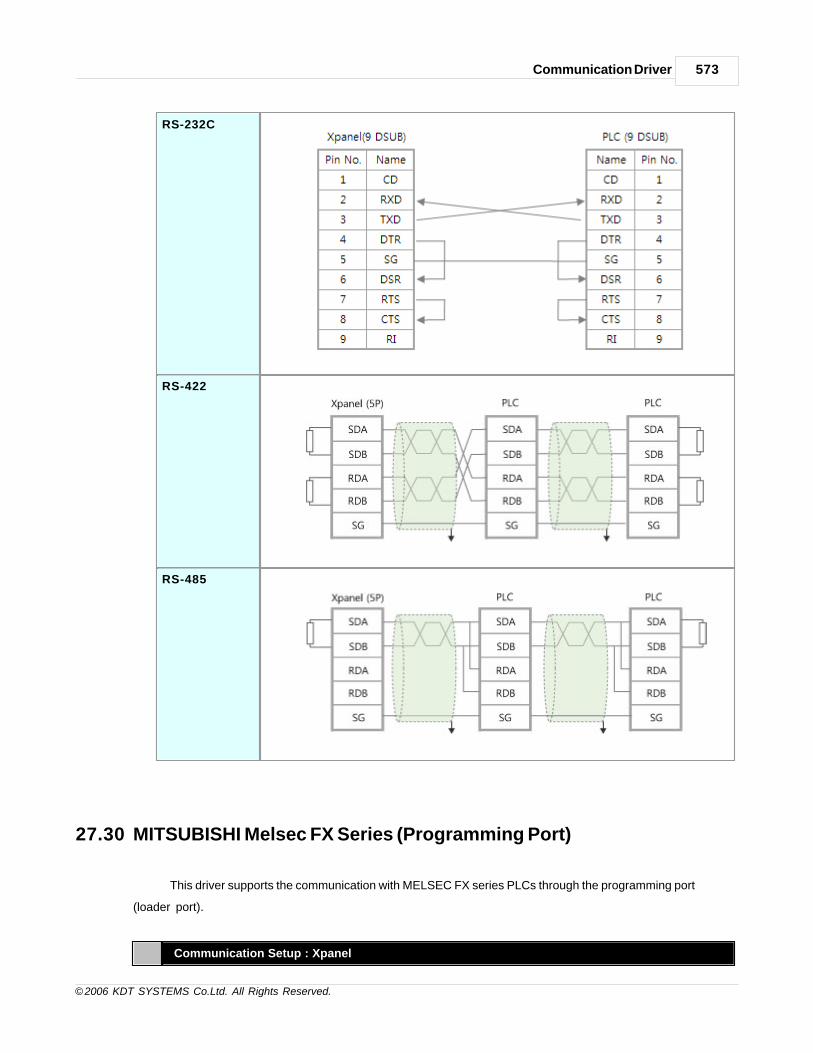
Communication Driver 573
© 2006 KDT SYSTEMS Co.Ltd. All Rights Reserved.
RS-232C
RS-422
RS-485
27.30 MITSUBISHI Melsec FX Series (Programming Port)
This driver supports the communication with MELSEC FX series PLCs through the programming port
(loader port).
Communication Setup : Xpanel

CIMON-Xpanel574
© 2006 KDT SYSTEMS Co.Ltd. All Rights Reserved.
Createa newDevice
For creating a new device activate the menu ‘Tools’- >’I/O Devices’ or icon in tool-bar.
Following picture
shows the first step of creating a new device.
I/O Device Name : Give a device name. This name will be used in the TAG configuration window
of database
accompanied by the ‘Station Name’.
Selectadevicetype
I/O Device type : ' MITSUBISHI Melsec FX Loader '
After selecting the ‘OK’ button of previous step, ‘Serial Communication Configuration’ dialog box will
be popped up as shown in following picture.

Communication Driver 575
© 2006 KDT SYSTEMS Co.Ltd. All Rights Reserved.
In this window, select the ‘Device Type’ as ‘MITSUBISHI MELSEC FX Loader’ and configure the
proper serial
communication parameters. The programming port of FX PLC uses fixed communication
parameters.
Ensure that communication parameters are configured as followings.

CIMON-Xpanel576
© 2006 KDT SYSTEMS Co.Ltd. All Rights Reserved.
Baud rate 9,600 bps
Parity None
Data bits 8 Bits
Stop bits 1 Bits
RS422A
Channel
RS422A Channel( COM1)
Createastation
Move to the ‘Station’ tab of ‘Serial Communication Configuration’ dialog box.
In this dialog box, all the connected PLC stations can be configured and registered to the Xpanel.
Each field can be configured with following rules

Communication Driver 577
© 2006 KDT SYSTEMS Co.Ltd. All Rights Reserved.
Station Name Give a name to the PLC. This name will be used in the database window
accompanied with the ‘Device Name’.
Station Type Select the “FX Loader” type. No other items can be chosen.
Network ID This field has no effect.
Station No. This field has no effect in this communication driver. Only one PLC can be
connected through the programming port driver. Therefore, there is no need
to use station number.
Socket Port No. 2005
The exclusive use of GLOFA Enet supporting socket number is TCP 2004, UDP
2005.
16Bit Data
Swap
This field has no effect.
32Bit Data
Swap
This field has no effect.
Using
Checksum
These fields have no effect. And this communication driver always checks the
check-sum.
Comm. Error
Message Pop
Up
If this item is checked, Xpanel displays a communication error notification
message at every Rx and Tx error.
Otherwise(unchecked), Xpanel does not display the message at data receive
error. Only when there is data transmit (writing a TAG value to the station)
error, the notification message is popped up. This message box will be closed
automatically about 5 seconds after.
Supported PLC Memories
Memory Sym CPU Format Data
FX0n FX,FX2c FX2n
Input X X0000-X0177 X0000-X0337 X0000-X0267 Octal Bit
Output Y Y0000-Y0177 Y0000-Y0337 Y0000-Y0267 Octal Bit
Aux Relay M M0000-M0511 M0000-M1535 M0000-M3071 Decimal Bit

CIMON-Xpanel578
© 2006 KDT SYSTEMS Co.Ltd. All Rights Reserved.
Special Relay M M8000-M8254 M8000-M8255 M8000-M8255 Decimal Bit
Timer (Contact) T T000-T063 T000-T255 T000-T255 Decimal Bit
Counter (Contact) C C000-C254 C000-C255 C000-C255 Decimal Bit
Status Relay S S0000-S0127 S0000-S0999 S0000-S0999 Decimal Bit
Data Register D D0000-D8255 D0000-D8255 D0000-D8255 Decimal Word
Timer (Cur-value) TN TN000-TN063 TN000-TN255 TN000-TN255 Decimal Word
Counter (Cur-value) CN CN000-CN254 CN000-CN255 CN000-CN255 Decimal Word
Wiring Diagram
RS422A
27.31 MITSUBISHI Melsec Q Series (Programming Port)
This driver supports the communication with MELSEC Q series PLCs through the programming port (loader
port).
Communication Setup : PLC (GX Developer)
Following configuration is needed in PLC side.
This can be done at the "PLC Parameter-Serial" setup window of GX Developer as shown in the following
picture.
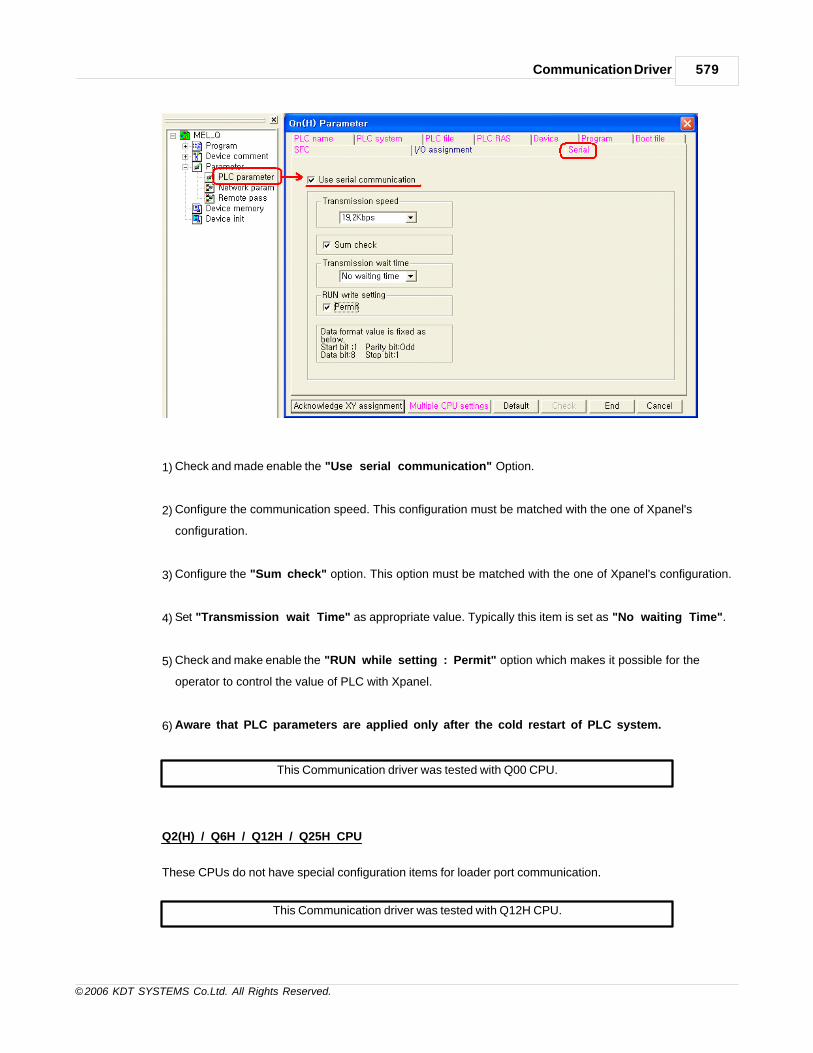
Communication Driver 579
© 2006 KDT SYSTEMS Co.Ltd. All Rights Reserved.
1) Check and made enable the "Use serial communication" Option.
2) Configure the communication speed. This configuration must be matched with the one of Xpanel's
configuration.
3) Configure the "Sum check" option. This option must be matched with the one of Xpanel's configuration.
4) Set "Transmission wait Time" as appropriate value. Typically this item is set as "No waiting Time".
5) Check and make enable the "RUN while setting : Permit" option which makes it possible for the
operator to control the value of PLC with Xpanel.
6) Aware that PLC parameters are applied only after the cold restart of PLC system.
This Communication driver was tested with Q00 CPU.
Q2(H) / Q6H / Q12H / Q25H CPU
These CPUs do not have special configuration items for loader port communication.
This Communication driver was tested with Q12H CPU.

CIMON-Xpanel580
© 2006 KDT SYSTEMS Co.Ltd. All Rights Reserved.
Communication Setup : Xpanel
Createa newDevice
For creating a new device activate the menu ‘Tools’- >’I/O Devices’ or icon in tool-bar.
Following picture
shows the first step of creating a new device.
I/O Device Name : Give a device name. This name will be used in the TAG configuration window
of database
accompanied by the ‘Station Name’.
Selectadevicetype
I/O Device Type : ' MITSUBISHI Melsec Q Loader(Q00/01), MITSUBISHI Melsec Q Loader
(Q02/06/12/25) '
After selecting the ‘OK’ button of previous step, ‘Serial Communication Configuration’ dialog
box will be popped up. Proceed the further configuration according to the type of PLC CPU. Please
notice that the communication parameter combination shown in the following box is the only one
allowed in Q series CPU programming port. (Regardless of the type of CPU, no other configuration
is allowed.)

Communication Driver 581
© 2006 KDT SYSTEMS Co.Ltd. All Rights Reserved.
· Parity : Odd
· Data Bits : 8 Bits
· Stop Bit : 1 Bit
Q00CPU / Q01CPU
If the connecting CPU type is Q00 or Q01, then select the 'MITSUBISHI MELSEC Q Loader
(Q00/Q01)' device type.
Q2(H) / Q6H / Q12H / Q25H
If the connecting CPU type is Q02(H), Q06H, Q12H or Q25H,

CIMON-Xpanel582
© 2006 KDT SYSTEMS Co.Ltd. All Rights Reserved.
then select the 'MITSUBISHI MELSEC Q Loader (Q02/Q06/Q12/Q25)' device type.
Createastation
Move to the ‘Station’ tab of ‘Serial Communication Configuration’ dialog box.
In this dialog box, all the connected PLC stations can be configured and registered to the Xpanel.
Each field can be configured with following rules

Communication Driver 583
© 2006 KDT SYSTEMS Co.Ltd. All Rights Reserved.
Station Name Give a name to the PLC. This name will be used in the database window
accompanied with the ‘Device Name’.
Station Type Choose the type of connected PLC CPU.
[Note]
If the connecting CPU is Q01CPU, then choose "Q00CPU". These two CPUs
have no difference in Xpanel communication driver.
Network ID This field has no effect.

CIMON-Xpanel584
© 2006 KDT SYSTEMS Co.Ltd. All Rights Reserved.
Station No. Specify the station number in decimal form (0..254). This number has no
meaning in peer to peer communication. Usually, this station number is
configured as zero(0).
16Bit Data
Swap
This field has no effect.
32Bit Data
Swap
This field has no effect.
Using
Checksum
This configuration should be matched with the same configuration item of
PLC CPU. Ensure that this option is checked with the same status in both
side. (Verify the check status of "Sum Check" item of GX Developer.
Comm. Error
Message Pop
Up
If this item is checked, Xpanel displays a communication error notification
message at every Rx and Tx error.
Otherwise(unchecked), Xpanel does not display the message at data receive
error. Only when there is data transmit (writing a TAG value to the station)
error, the notification message is popped up. This message box will be closed
automatically about 5 seconds after.
Supported PLC Memories
Q00CPU / Q01CPU
Memory Area Symbol Range Notation Bit / Word
Input Relay X X0000-X07FF 16 Bit
Output Relay Y Y0000-Y07FF 16 Bit
Internal Relay M M0000-M8191 10 Bit
SM SM0000-SM1023 10 Bit
Latch Relay L L0000-L2047 10 Bit
Link Relay B B0000-B07FF 16 Bit
SB SB0000-SB07FF 16 Bit
Edge Relay V V0000-V1023 10 Bit
Annunciator F F0000-F1023 10 Bit
Timer Contact TS TS0000-TS0511 10 Bit
Timer Clear TC TC0000-TC0511 10 Bit
Timer Current Value TN TN0000-TN0511 10 Word
Counter Contact CS CS0000-CS0511 10 Bit
Counter Coil CC CC0000-CC0511 10 Bit
Counter Current Value CN CN0000-CN0511 10 Word
Data RegisterD D00000-D11135 10 Word
SD SD0000-SD1023 10 Word
Lin Register W W0000-W07FF 16 Word
SW SW0000-SW03FF 16 Word

Communication Driver 585
© 2006 KDT SYSTEMS Co.Ltd. All Rights Reserved.
Q02(H) / Q06H / Q12H / Q25H
Memory Area Symbol Range Notation Bit / Word
Input Relay X X0000-X1FFF 16 Bit
Output Relay Y Y0000-Y1FFF 16 Bit
Internal Relay M M0000-M8191 10 Bit
SM SM0000-SM1023 10 Bit
Latch Relay L L0000-L8191 10 Bit
Link Relay B B0000-B1FFF 16 Bit
Edge Relay V V0000-V2047 10 Bit
Annunciator F F0000-F2047 10 Bit
Timer Clear TC TC0000-TC2047 10 Bit
Timer Current Value TN TN0000-TN2047 10 Word
Counter Coil CC CC0000-CC1023 10 Bit
Counter Current Value CN CN0000-CN1023 10 Word
Data RegisterD D00000-D12287 10 Word
SD SD0000-SD2047 10 Word
Lin RegisterW W0000-W1FFF 16 Word
SW SW0000-SW07FF 16 Word
Wiring Diapram
RS232C

CIMON-Xpanel586
© 2006 KDT SYSTEMS Co.Ltd. All Rights Reserved.
27.32 MITSUBISHI Melsec FX2N-10/20GM(Programming Port)
This driver provides the software interface and communication protocol between XPanel and Melsec FX2N-
10/20GM PLCs.
Communication Setup : Xpanel
Create a newSetup For creating a new device activate the menu ‘Tools’- >’I/O Devices’ or icon in tool-bar.
Following picture shows the first step of creating a new device.
I/O Device Name : Give a device name.
This name will be used in the TAG configuration window of database accompanied by the
‘Station Name’.

Communication Driver 587
© 2006 KDT SYSTEMS Co.Ltd. All Rights Reserved.
Select anetwork type
I/O Device Name : MITSUBISHI MELSEC FX2N-10/20GM Loader
After selecting the ‘OK’ button of previous step, ‘Serial Communication Configuration ’ dialog
box will be popped up as shown in following picture.
In this window, select the ‘Device Type’ as ‘MITSUBISHI MELSEC FX2N-10/20GM’ and
appropriate
communication parameters. Those parameters must be matched with the PLC.
Communication parameters should be configured as shown in the following table.
Baud Rate 9600
Parity Even
CIMON-Xpanel588
© 2006 KDT SYSTEMS Co.Ltd. All Rights Reserved.
Data Bits 8 Bits
Stop Bits 1Bits
Comm.Type RS422

Communication Driver 589
© 2006 KDT SYSTEMS Co.Ltd. All Rights Reserved.
Create a station Move to the ‘Station’ tab of ‘Serial Communication Configuration’ dialog box. In this dialog box,
all the connected
PLC stations can be configured and registered to the XPanel. Each field can be configured with
following rules.
Station Name Give a name to the PLC. This name will be used in the database window accompanied with the‘Device Name’.
Station Type Choose the ‘FX2N-10/20GM’. (No other type can be selected.)
Network ID This field has no meaning in this driver. (ignored in runtime)
Station No. This number must be matched with the one of PLC.
16Bit Data Swap This field has no meaning in this driver.

CIMON-Xpanel590
© 2006 KDT SYSTEMS Co.Ltd. All Rights Reserved.
32Bit Data Swap This field has no meaning in this driver.
Using
Checksum
This field has no meaning in this driver.
Comm. Error
Message Pop
Up
If this item is checked, XPanel displays a communication error
notification message
at every Rx and Tx error.
Otherwise(unchecked), XPanel does not display the message at data
receive error.
Only when there is data transmit (writing a TAG value to the station)
error, the
notification message is popped up. This message box will be closed
automatically
about 5 seconds after.
Address Notation
Following table shows the list of devices which can be referenced in XPanel database..
Symbol
Memory Analog Tag Digital Tag Format Data
10GM 20GM 10GM 20GM
M Aux Relay - - M000-M511 M000-M511 Dec Bit
SM SpecialRelay
- - SM0000-SM0175
SM0000-SM0175
Dec Bit
X Input - - X000-X003X375-X377
X000-X067X372-X377
Oct Bit
Y Output - - Y000-Y005 Y000-Y067 Oct Bit
D DataRegister
D000-D1999 D000-D3999 - - Dec Word
SD Special dataregister
SD000-SD0313
SD000-SD0599
- - Dec Word
V - V000-V007 V000-V007 - - Dec Word
Z - Z000-Z007 Z000-Z007 - - Dec Dword
* SM address matches originally to M address based on M9000 at PLC, also SD matches D
address based on D9000.
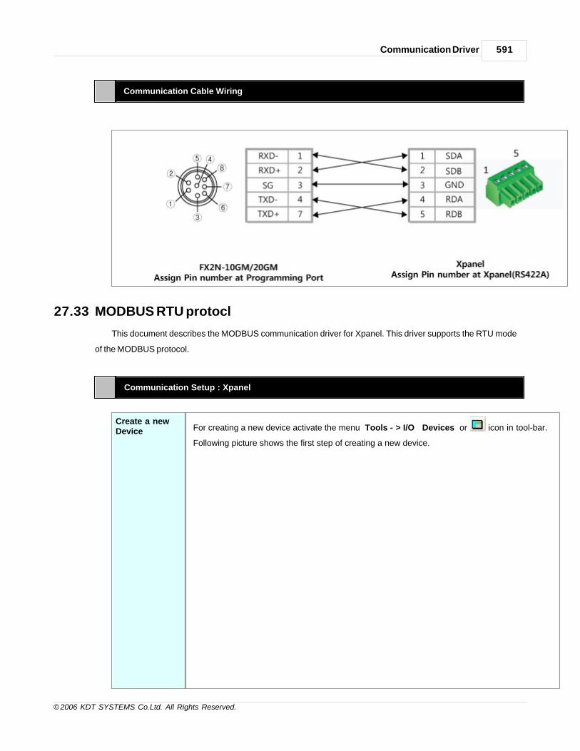
Communication Driver 591
© 2006 KDT SYSTEMS Co.Ltd. All Rights Reserved.
Communication Cable Wiring
27.33 MODBUS RTU protocl
This document describes the MODBUS communication driver for Xpanel. This driver supports the RTU mode
of the MODBUS protocol.
Communication Setup : Xpanel
Create a newDevice For creating a new device activate the menu ‘Tools’- >’I/O Devices’ or icon in tool-bar.
Following picture shows the first step of creating a new device.

CIMON-Xpanel592
© 2006 KDT SYSTEMS Co.Ltd. All Rights Reserved.
I/O Device Name : Give a device name. This name will be used in the TAG configuration
window of database
accompanied by the ‘Station Name’.
Select a devicetype
I/O Device Type : MODBUS RTU Protocol
After selecting the ‘OK’ button of previous step, ‘Serial Communication Configuration’
dialog box will be popped
up as shown in following picture.

Communication Driver 593
© 2006 KDT SYSTEMS Co.Ltd. All Rights Reserved.
In this window, select the ‘Device Type’ as ‘MODBUS RTU Protocol’ and configure the
proper serial communication parameters. Ensure that those parameters are matched with the
device’s configuration.
Create a station Move to the ‘Station’ tab of ‘Serial Communication Configuration’ dialog box.
In this dialog box, all the connected PLC stations can be configured and registered to the
Xpanel.
Each field can be configured with following rules.

CIMON-Xpanel594
© 2006 KDT SYSTEMS Co.Ltd. All Rights Reserved.
Station Name Give a name to the PLC. This name will be used in the database window
accompanied with the ‘Device Name’.
Station Type Choose the type of connected PLC among the “Modbus RTU”.
Network ID This field has no effect.
Station No. Specify a decimal number between 1 and 247.
16Bit Data
Swap
This option swaps bytes of all word or double word sized data. Following
diagram shows an example of byte swapping.
Almost all of the data type will be influenced by this option except
INT8 / UINT8 / BCD8 / UBCD8.
32Bit Data
Swap
This option swaps words of all double word sized data. Following diagram
shows an example of word swapping.

Communication Driver 595
© 2006 KDT SYSTEMS Co.Ltd. All Rights Reserved.
NT32 / UINT32 / BCD32 / UBCD32 / FLOAT type of TAG values will be
influenced by this option.
Using
Checksum
This field has no effect. This MODBUS driver always checking the BCC.
Comm. Error
Message Pop
Up
If this item is checked, Xpanel displays a communication error
notification message at every Rx and Tx error. Otherwise(unchecked),
Xpanel does not display the message at data receive error. Only when
there is data transmit (writing a TAG value to the station) error, the
notification message is popped up. This message box will be closed
automatically about 5 seconds after.
Address & Function Codes
Following table shows the list of valid address range and used MODBUS function codes for each address
area.
The symbol character has to be placed in the first position of address string. The address number follows
the symbol character.
Area Symbol Analog TAG Digital TAG Read Write
Coil 0 000001 - 029999 (1) 1 5
Input 1 100001 - 129999 2
Holding Register 4 400001 - 429999 3 6, 16 (2)
Input Register 3 300001 - 329999 4
1) The symbol character does not have the number property. For example, 400100 and 4100 designate the same
memory area (Holding register 100).
2) The code 16 is issued when a double word write or the recipe write function is activated. A single word write
uses the code 6.
The memory areas listed above are provided for general purposes. The actual available memory area and
range of each area should be
checked with the manual of connecting device. The ‘Read’/’Write’ columns show the used MODBUS function
codes in this communication driver.

CIMON-Xpanel596
© 2006 KDT SYSTEMS Co.Ltd. All Rights Reserved.
Communication Cable Wiring
XPANEL COM/CPM2RS232C
XPANEL COM1RS422/485
Above picture shows the RS232C and RS422/485 ports of Xpanel. Refer to the manual of your device for
signal description.
In case of the RS232C ports, Xpanel provides the standard DB9 RS232C pin assignment. Typically RD, TD
and SG pins are enough to
communicate with general MODBUS device.
27.34 MODBUS TCP protocl
This document describes the MODBUS communication driver for Xpanel. This driver supports the TCP mode
of the MODBUS protocol.
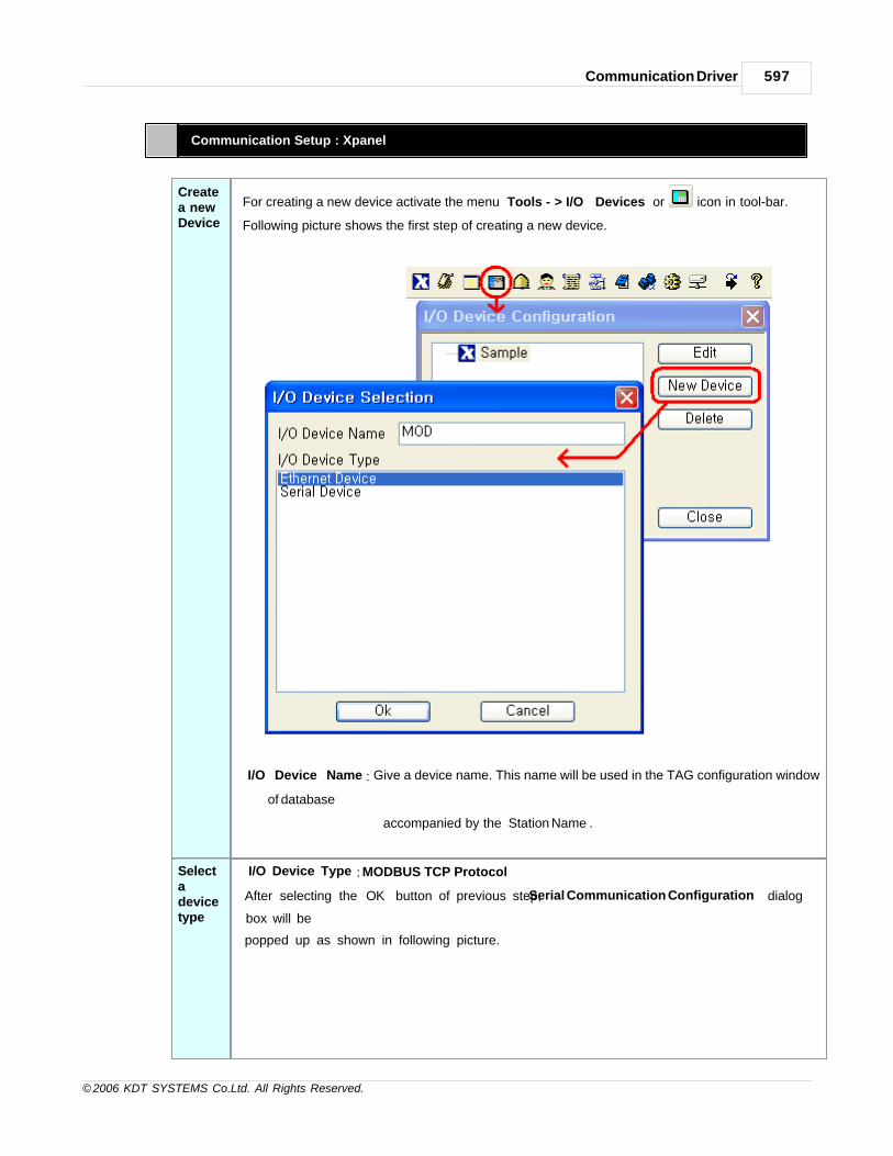
Communication Driver 597
© 2006 KDT SYSTEMS Co.Ltd. All Rights Reserved.
Communication Setup : Xpanel
Createa newDevice
For creating a new device activate the menu ‘Tools’- >’I/O Devices’ or icon in tool-bar.
Following picture shows the first step of creating a new device.
I/O Device Name : Give a device name. This name will be used in the TAG configuration window
of database
accompanied by the ‘Station Name’.
Selectadevicetype
I/O Device Type : MODBUS TCP Protocol
After selecting the ‘OK’ button of previous step, ‘Serial Communication Configuration’ dialog
box will be
popped up as shown in following picture.

CIMON-Xpanel598
© 2006 KDT SYSTEMS Co.Ltd. All Rights Reserved.
In this window, select the ‘Device Type’ as ‘MODBUS TCP’ and configure the proper ehternet
communication parameters. Ensure that those parameters are matched with the device’s
configuration.
Createastation
Move to the ‘Station’ tab of ‘Ethernet Communication Configuration’ dialog box.
In this dialog box, all the connected PLC stations can be configured and registered to the
Xpanel.
Each field can be configured with following rules.

Communication Driver 599
© 2006 KDT SYSTEMS Co.Ltd. All Rights Reserved.
Station Name Give a name to the PLC. This name will be used in the database window
accompanied with the ‘Device Name’.
Station Type Choose the type of connected PLC among the “Modbus TCP”.
Network ID Sum of MODBUS/TCP devices here its own station number.
Socket Port No The socket number should be configured as 502. This port number is
dedicated for MODBUS/TCP.
16Bit Data
Swap
This option swaps bytes of all word or double word sized data. Following
diagram shows an example of byte swapping.
Almost all of the data type will be influenced by this option except INT8 /
UINT8 / BCD8 / UBCD8.
32Bit Data
Swap
This option swaps words of all double word sized data. Following diagram
shows an example of word swapping.
NT32 / UINT32 / BCD32 / UBCD32 / FLOAT type of TAG values will be
influenced by this option.
Using
Checksum
This field has no effect. This MODBUS driver always checking the BCC.
Comm. Error If this item is checked, Xpanel displays a communication error notification

CIMON-Xpanel600
© 2006 KDT SYSTEMS Co.Ltd. All Rights Reserved.
Message Pop
Up
message at every Rx and Tx error. Otherwise(unchecked), Xpanel does
not display the message at data receive error. Only when there is data
transmit (writing a TAG value to the station) error, the notification message
is popped up. This message box will be closed automatically about 5
seconds after.
Address & Function Codes
Following table shows the list of valid address range and used MODBUS function codes for each address
area.
The symbol character has to be placed in the first position of address string. The address number follows
the symbol character.
Area Symbol Analog TAG Digital TAG Read Write
Coil 0 000001 - 029999 (1) 1 5
Input 1 100001 - 129999 2
Holding Register 4 400001 - 429999 3 6, 16 (2)
Input Register 3 300001 - 329999 4
1) The symbol character does not have the number property. For example, 400100 and 4100 designate the
same memory area (Holding register 100).
2) The code 16 is issued when a double word write or the recipe write function is activated. A single word
write uses the code 6.
The memory areas listed above are provided for general purposes. The actual available memory area and
range of each area should be
checked with the manual of connecting device. The ‘Read’/’Write’ columns show the used MODBUS
function codes in this communication driver.
Communication Cable Wiring
This interface is satisfied with standard IEEE802.3 about the 10BaseT/100BaseTX.
You can make cable and allocation pin number of RJ45 as the following figure.
RJ45 Connector RJ45 Jack
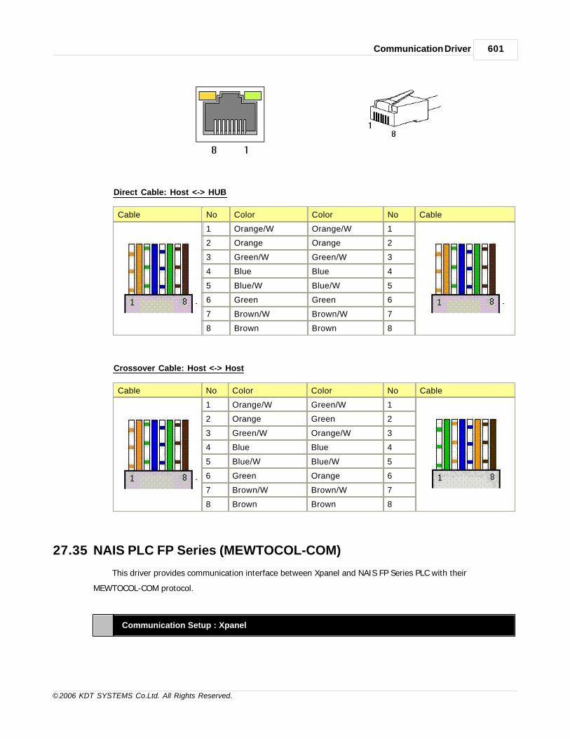
Communication Driver 601
© 2006 KDT SYSTEMS Co.Ltd. All Rights Reserved.
Direct Cable: Host <-> HUB
Cable No Color Color No Cable
1 Orange/W Orange/W 1
2 Orange Orange 2
3 Green/W Green/W 3
4 Blue Blue 4
5 Blue/W Blue/W 5
6 Green Green 6
7 Brown/W Brown/W 7
8 Brown Brown 8
Crossover Cable: Host <-> Host
Cable No Color Color No Cable
1 Orange/W Green/W 1
2 Orange Green 2
3 Green/W Orange/W 3
4 Blue Blue 4
5 Blue/W Blue/W 5
6 Green Orange 6
7 Brown/W Brown/W 7
8 Brown Brown 8
27.35 NAIS PLC FP Series (MEWTOCOL-COM)
This driver provides communication interface between Xpanel and NAIS FP Series PLC with their
MEWTOCOL-COM protocol.
Communication Setup : Xpanel

CIMON-Xpanel602
© 2006 KDT SYSTEMS Co.Ltd. All Rights Reserved.
Createa newDevice
For creating a new device activate the menu ‘Tools’- >’I/O Devices’ or icon in tool-bar.
Following picture shows the first step of creating a new device.
I/O Device Name : Give a device name. This name will be used in the TAG configuration window
of database
accompanied by the ‘Station Name’.
Selectadevicetype
I/O Device type : NAIS FPO MEWTOCOL-COM
After selecting the ‘OK’ button of previous step, ‘Serial Communication Configuration’ dialog
box will be popped up as shown in following picture.
Select the ‘NAIS FPO MEWTOCOL-COM’ in ‘Device Type’ combo-box of following dialog box. And
then, configure the communication parameters appropriately. Ensure that parameters are matched
with those of PLC side.

Communication Driver 603
© 2006 KDT SYSTEMS Co.Ltd. All Rights Reserved.
Createastation
Move to the ‘Station’ tab of ‘Serial Communication Configuration’ dialog box. The PLCs to
communicate with must be registered in the ‘Station’ Tab. ‘Add Station’ button pops up a station
configuring dialog box. A station can be defined with its station number on this dialog box. Each
field can be configured with following guideline.

CIMON-Xpanel604
© 2006 KDT SYSTEMS Co.Ltd. All Rights Reserved.
Station Name Give a name to the PLC. This name will be used in the database window
accompanied with the ‘Device Name’.
Station Type Choose the ‘NAIS FPO’. (No other type can be selected.)
Network ID This field has no effect.
Station No Assign a station number. It can be a decimal number between 1 and 32.
16Bit Data
Swap
This field has no effect.
32Bit Data
Swap
This field has no effect.
Using
Checksum
This field has no effect.
Comm. Error
Message Pop
If this item is checked, Xpanel displays a communication error notification
message at every Rx and Tx error.

Communication Driver 605
© 2006 KDT SYSTEMS Co.Ltd. All Rights Reserved.
Up Otherwise(unchecked), Xpanel does not display the message at data receive
error. Only when there is data transmit (writing a TAG value to the station)
error, the notification message is popped up. This message box will be
closed automatically about 5 seconds after.
Address Notation
The address of TAG in Xpanel has the following format.
Format Type Format Example
Dec. [Symbol][Decimal Address] DT0010 / T0100
Dec_Hex. [Symbol][Decimal Address][Hex Bit Number] X012F
Symbol Area AnalogTAG
Digital TAG
AddressFormat
DecimalAddress
Access
X External Input O Dec_Hex 00-12 R
Y External Output O Dec_Hex 00-12 R/W
R Internal Relay O Dec_Hex 000-903 R/W
L Link Relay O Dec_Hex 000-999 R/W
C Counter O Dec 000-143 R
T Timer O Dec 000-143 R
WX External Input Word O Dec 00-12 R
WY External Output Word O Dec 00-12 R/W
WR Internal Relay Word O Dec 000-903 R/W
DT Data Register O Dec 0-9121 R/W
FL File Register O Dec 0-9999 R/W
LD Link Data Register O Dec 0-9999 R/W
Communication Cable Wiring

CIMON-Xpanel606
© 2006 KDT SYSTEMS Co.Ltd. All Rights Reserved.
27.36 OMRON HostLink
This version of driver uses C-mode command in OMRON HostLink protocol.
Communication Setup : Xpanel
Createa newDevice
For creating a new device activate the menu ‘Tools’->’I/O Devices’ or icon in tool-bar.
Following picture shows the first step of creating a new device.

Communication Driver 607
© 2006 KDT SYSTEMS Co.Ltd. All Rights Reserved.
I/O Device Name : Give a device name. This name will be used in the TAG configuration window of
database
accompanied by the ‘Station Name’.
Selectadevicetype
I/O Device type : ' OMRON PLC(HostKink) '
After selecting the ‘OK’ button of previous step, ‘Serial Communication Configuration’ dialog box will be
popped
up as shown in following picture.

CIMON-Xpanel608
© 2006 KDT SYSTEMS Co.Ltd. All Rights Reserved.
In this window, select the ‘Device Type’ as ‘OMRON PLC (HostLink)’ and configure the proper serial
communication parameters. Ensure that those parameters are matched with PLC configuration.
Createastation
Move to the ‘Station’ tab of ‘Serial Communication Configuration’ dialog box.
In this dialog box, all the connected PLC stations can be configured and registered to the Xpanel.
Each field can be configured with following rules.

Communication Driver 609
© 2006 KDT SYSTEMS Co.Ltd. All Rights Reserved.
Station Name Give a name to the PLC. This name will be used in the database window
accompanied with the ‘Device Name’.
Station Type Choose the ‘HostLink’. (No other type can be selected.)
Network ID This field has no effect.
Station No. Specify a decimal number between 0 and 31.
16Bit Data
Swap
This field has no effect.
32Bit Data
Swap
This field has no effect.
Using
Checksum
This field has no effect.
Comm. Error
Message pop
If this item is checked, Xpanel displays a communication error notification
message at every Rx and Tx error.

CIMON-Xpanel610
© 2006 KDT SYSTEMS Co.Ltd. All Rights Reserved.
Up Otherwise(unchecked), Xpanel does not display the message at data receive
error. Only when there is data transmit (writing a TAG value to the station)
error, the notification message is popped up. This message box will be closed
automatically about 5 seconds after.
PLC Mode
Omron PLC can be written when its mode is monitor. So you must change the mode to monitor.
Please set the value of DM6600 to 0101h. Even though the PLC power goes out, it remains to monitor
mode.
You can only change the DM6600 by program mode.
Supported PLC Memories
Area Symbol Analog TAG Digital TAG Remark
DM area D D0000 D9999 D0000.00 D0000.15D9999.00 D9999.15
(1)
CIO area IR IR0000 IR6143IR0000.00 IR0000.15IR6143.00 IR6143.15
AR area A A0000 A0959 A0000.00 A0000.15A0959.00 A0959.15
(1), (2)
HR area H H0000 H0511H0000.00 H0000.15H0511.00 H0511.15
T/C status TC not supported TC0000 TC4095 (3)
T/C p. value PV PV0000 PV4095 not supported (3)
LR area L L0000 L0199 L0000.00 L0000.15L0199.00 L0199.15
EM area EE0_0000 E0_9999EC_0000 EC_9999
E0_0000.00 E0_0000.15EC_9999.00 EC_9999.15
(1), (4)
(1) If the address of this area was used in digital tag, control functionalities are not supported. Xpanel
cannot set/reset these points.
(2) A0000 A0447 address area cannot be modified by Xpanel. (Read only area)
(3) Timer : T0000 T2143 area was mapped to TC0000 - TC2143 (PV0000 - PV2143)
Counter : C0000 C2143 area was mapped to TC2148 - TC4095 (PV2148 - PV4095)

Communication Driver 611
© 2006 KDT SYSTEMS Co.Ltd. All Rights Reserved.
(4) Bank of EM area must be denoted by one hexadecimal character (‘0’ ‘C’) as following example.
· Digital Tag : E[bank]_[word no].[2 digit bit no] (EA_1000.05 : bit5 of E1000 in bank ‘A’)
· Analog Tag : E[bank]_[word no] (EC_32 : E0032 of bank ‘C’)
(5) Bit location of digital Tag must be denoted by 2 digits decimal number (‘00’ ‘15’) with dot (’.’)
separator.
(exception : Timer/Counter area is digital point by itself).
Wiring Diagram
RS232C
C Series RS422A

CIMON-Xpanel612
© 2006 KDT SYSTEMS Co.Ltd. All Rights Reserved.
CS/CJ Series
RS422A
27.37 OMRON FINS Ethernet
OMRON FINS Protocol is used to communicate with OMRON PLC through FINS Ethernet..
Communication Setup : Xpanel
Createa newDevice
For creating a new device activate the menu ‘Tools’->’I/O Devices’ or icon in tool-bar.
Following picture shows the first step of creating a new device.

Communication Driver 613
© 2006 KDT SYSTEMS Co.Ltd. All Rights Reserved.
I/O Device Name : This device name is used when you set up Station and Database to register tags.
Write I/O Device Name and select Ethernet Device and then click ‘OK’.
Selectadevicetype
I/O Device type : ' OMRON CS/CJ Series Enet '
After writing device name, 'Ethernet Communication Configuration' window is shown as below.

CIMON-Xpanel614
© 2006 KDT SYSTEMS Co.Ltd. All Rights Reserved.
Select 'OMRON CS/CJ Series Enet' at Device type and click 'TCP'.
If UDP is setup at PLC Communication configuration, 'UDP' can be used.
- Set "Network ID" and "Node ID". Xpanel "Unit ID" of Xpanel is fixed at '0'.
- Set "Time out" and "Retry No" according to network condition.
Createastation
Click 'Station' at 'Ethernet Communication Configuration' window. You can register device to communicate with
Xpanel.

Communication Driver 615
© 2006 KDT SYSTEMS Co.Ltd. All Rights Reserved.
Station Name Give a name to the PLC. This name will be used in the database window accompanied
with the ‘Device Name’.
Station Type Choose the ‘HostLink’. (No other type can be selected.)
Network ID This field has no effect.
Node ID Set "Node ID" of PLC. Some PLC use 4th digit number of IP address as "Node ID"
Unit ID Set "Unit ID" of PLC. Generally it is '0'
IP Address Write IP address of PLC.
Socket Port
number
Default is 9600. If you change this value in PLC, write that number.
16 Bit Data Swap Not used
32Bit Data Swap Not used
String Data It exchanges front and back word of string tag.

CIMON-Xpanel616
© 2006 KDT SYSTEMS Co.Ltd. All Rights Reserved.
Swap
Comm. Error
Message Pop up
It is used to show Comm. Error message on the screen when Xpanel detects
sending/receiving error. 'Comm. Error Message' will be disappeared in 5 sec.
Fixed XPANEL
Socket Port
Not used
PLC Mode
1. CS/CJ Series Communication setting. (Example. CJ2M CPU35 )
1) External Rotary Switch setting
(1) Node number shows hexadecimal on screen.
(2) Set UNIT number
(3) Set NODE number
2) Built-in EtherNet/IP Port setting
(1) Select IO Table/ Unit setting.

Communication Driver 617
© 2006 KDT SYSTEMS Co.Ltd. All Rights Reserved.
(2) Select [1500] CJ2M-EIP21(Built In EtherNet/IP Port for CJ2M)(Unit : 0) at Inner Port/Inner Board

CIMON-Xpanel618
© 2006 KDT SYSTEMS Co.Ltd. All Rights Reserved.
Select “TCP/IP” and write IP number of PLC EtherNet/IP at “IP Address”
(3) lSelect “FINS/TCP” and “Service Port” and check “Node ID”.

Communication Driver 619
© 2006 KDT SYSTEMS Co.Ltd. All Rights Reserved.
(4) Click red box as above picture.

CIMON-Xpanel620
© 2006 KDT SYSTEMS Co.Ltd. All Rights Reserved.
(5) Check Net , Node, and Unit.

Communication Driver 621
© 2006 KDT SYSTEMS Co.Ltd. All Rights Reserved.
(6) Select Start Routing table.
(7) Select “유니트 00(이더넷 /IP)” and insert CPU SIOU as above picture.

CIMON-Xpanel622
© 2006 KDT SYSTEMS Co.Ltd. All Rights Reserved.
2. NJ5xx Series ( Built-in EtherNet/IP Port )
1) Built-in EtherNet/IP Port setting
(1) Select Controller Setup -> Operation Settings.
(2) Refer to above picture and add setting to Local Network Table .

Communication Driver 623
© 2006 KDT SYSTEMS Co.Ltd. All Rights Reserved.
(3) Select Controller Setup -> Built-in EtherNet/IP Port Settings. Select TCP/IP Settings and set IP
address of PLC EtherNet/IP port.
(4) Select FINS Settings and set Service Port and check out Node ID. The 4th digit number of IP
Address(55) is used Node ID.

CIMON-Xpanel624
© 2006 KDT SYSTEMS Co.Ltd. All Rights Reserved.
2) FINS Data Block Registration
(1) Select Data Global Variables.
(2) Click the right button of mouse and select ‘Create New’.
(3) Register Name, Data Type and AT in Item.

Communication Driver 625
© 2006 KDT SYSTEMS Co.Ltd. All Rights Reserved.
Name : It is variable name which is used in PLC program.
Data Type : Register data type of variable. In order to make easy Communication setting, "Array
Type" is recommended.
AT : Register Device format through FINS communication. Refer to Device format as following.
Area Foramt
CIO Area %0 , %10...
Work Area %W0, %W100...
Holding Area %H0, %H50...
DM Area %D0, %D150...
EM Area %E0_0, %E1_10...
(4) After finishing setting, click "Controller" -> "Synchronization" to download it to PLC. Reset PLC
power just in case downloaded setting does not work properly
Supported PLC Memories
Area Symbol Digital TAG Analog TAG

CIMON-Xpanel626
© 2006 KDT SYSTEMS Co.Ltd. All Rights Reserved.
CIO Area CIO CIO0.0 ~ CIO6143.15 CIO0 ~ CIO6143
Work Area W W0.0 ~ W511.15 W0 ~ W511
Holding Area H H0.0 ~ H511.15 H0 ~ H511
AR Area A A0.0 ~ A959.15 A0 ~ A959
T/C Status TC TC0 ~ TC4095 -
T/C PValue PV - PV0 ~ PV4095
DM Area D D0.0 ~ D9999.15 D0 ~ D9999
EM Area EX_(x:0~F)
E0_0.0 ~ EF_32767.15 E0_0 ~ EF_32767
Communication Cable Wiring
This interface is satisfied with standard IEEE802.3 about the 10BaseT/100BaseTX.
You can make cable and allocation pin number of RJ45 as the following figure.
RJ45 Connector RJ45 Jack
Direct Cable: Host <-> HUB
Cable No Color Color No Cable
1 Orange/W Orange/W 1
2 Orange Orange 2
3 Green/W Green/W 3
4 Blue Blue 4
5 Blue/W Blue/W 5
6 Green Green 6
7 Brown/W Brown/W 7
8 Brown Brown 8
Crossover Cable: Host <-> Host
Cable No Color Color No Cable

Communication Driver 627
© 2006 KDT SYSTEMS Co.Ltd. All Rights Reserved.
1 Orange/W Green/W 1
2 Orange Green 2
3 Green/W Orange/W 3
4 Blue Blue 4
5 Blue/W Blue/W 5
6 Green Orange 6
7 Brown/W Brown/W 7
8 Brown Brown 8
27.38 PGuard(Serial)
This driver provides the software interface and communication protocol between Xpanel and PguardGateway.
Communication Setup : Xpanel
You can configure I/O device according to various kind of field equipments by using Xpanel Designer.
Configure the option of the example followed. More details about I/O device configuration in section “I/O
device configuration”.
Create a newdevice
To configure the communication device of LSIS PLC, Select 'Tools' -> 'I/O device' in the
menu or icon in
tool-bar , and then “I/O device configuration” dialog box will be shown up. And then click
[new device] button.
“I/O device selection” dialog box is shown up, select a device name and a device type as
the following figure.

CIMON-Xpanel628
© 2006 KDT SYSTEMS Co.Ltd. All Rights Reserved.
I/O Device Name :
Give a device name. This name will be used in the TAG configuration window of
database accompanied
by the ‘Station Name’.
Select a devicetype
Select a device type : 'PGuard gateway’ '
After selecting the ‘OK’ button of previous step, ‘Serial CommunicationConfiguration’ dialog box will be popped up as shown in following picture.
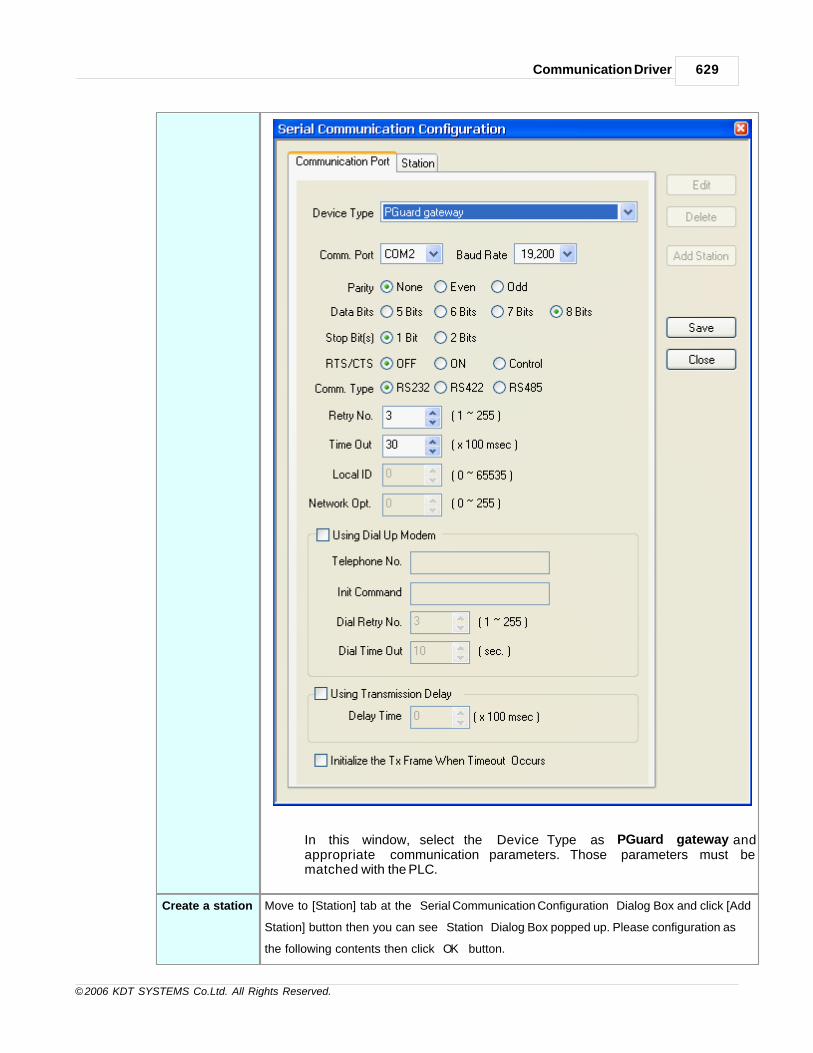
Communication Driver 629
© 2006 KDT SYSTEMS Co.Ltd. All Rights Reserved.
In this window, select the ‘Device Type’ as ‘PGuard gateway’andappropriate communication parameters. Those parameters must bematched with the PLC.
Create a station Move to [Station] tab at the “Serial Communication Configuration” Dialog Box and click [Add
Station] button then you can see “Station” Dialog Box popped up. Please configuration as
the following contents then click “OK” button.

CIMON-Xpanel630
© 2006 KDT SYSTEMS Co.Ltd. All Rights Reserved.
* Register only 1 station in driver ‘PGuard gateway’ to use.
Station Name Give a name to thr PLC. This name will be used in the database
window
accompanied with the 'Deviec Name' .
Station Type Choose the 'SGW'.(No other type can be slected)

Communication Driver 631
© 2006 KDT SYSTEMS Co.Ltd. All Rights Reserved.
Network ID This field has no effect.
Station No. Write designated station No. in PLC
16Bit Data
Swap
This field has no effect.
32Bit Data
Swap
This field has no effect.
Using
checksum
This field has no effect.
Comm.Error
Message Pop
up
If this is checked, XPanel displays a communication error notification
message at every RX and Tx Error.
Otherwise(unchecked), XPanel does not display the message at data
receive error. Only When there is data transmit (writing a TAG value
to the station) error, the notification message is poped up. This
message box will be closed automatically about 5 seconds after.
Address Notifiation
1 Command Devicel Notation : C00l It can be registered as Analog tag only.l It is used to command Device Scan to Xpanel. Only Writing is available
2 Read Buffer Devicel Notation : Bnn.mm.xx
i. nn : It means Received order, (0 15)ii. mm : It means nth time amount received data, (0 5)iii. Received data per device is 6Byte and it is fixed.iv. xx : Location of Bit, Only digital tag is available to use, (0 7)
ex) Analog, Word : B0.3 , B12.5 , B15.0Digital : B0.4.0 , B1.3.7 , B14.2.5
• It is used to word tag, word length should be less than 6.• Read only. Not support Writing.
27.39 SAIA S-BUS
This document described the SAIA S-BUS communication driver for Xpanel. This driver support the data mode
S-BUS protocol.
This driver provides the software interface and communication protocol between Xpanel and SAIA PCD families
via data mode S-BUS protocol.
Communication Setup : Xpanel

CIMON-Xpanel632
© 2006 KDT SYSTEMS Co.Ltd. All Rights Reserved.
Createa newDevice
For creating a new device activate the menu ‘Tools’- >’I/O Devices’ or icon in tool-bar.
Following picture shows the first step of creating a new device.
I/O Device Name : Give a device name. This name will be used in the TAG configuration window of
database
accompanied by the ‘Station Name’.
Selectadevicetype
I/O Device type : " SAIA S-BUS "
After selecting the 'OK' button of previous step, ‘Serial communication Configuration’ dialog box will
be popped
up as shown in following picture.

Communication Driver 633
© 2006 KDT SYSTEMS Co.Ltd. All Rights Reserved.
In this window, select the 'Device Type' as ‘SAIA S-BUS’ and configure the proper serial
communication parameters. Ensure that those parameters are matched with the device's configuration.
Createastation
Move to the ‘Station’ tab of ‘Ethernet Communication Configuration’ dialog box.
In this dialog box, all the connected PLC stations can be configured and registered to the XPanel.
Each field can be configured with following rules.
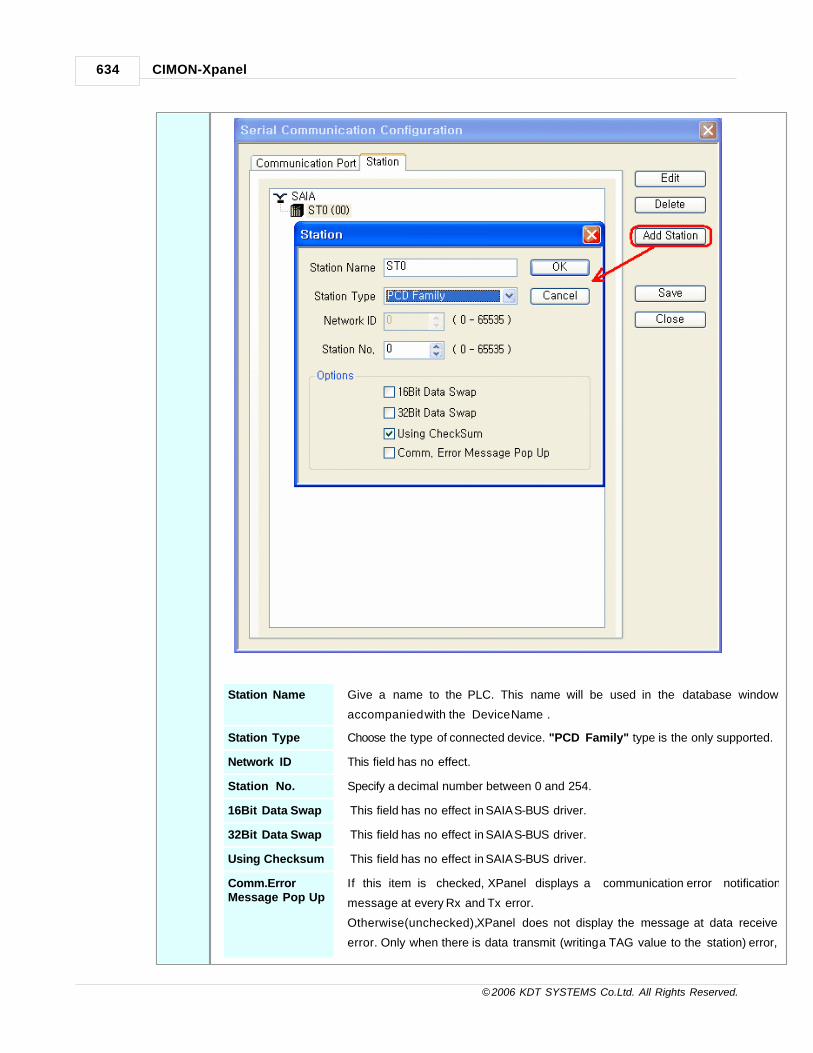
CIMON-Xpanel634
© 2006 KDT SYSTEMS Co.Ltd. All Rights Reserved.
Station Name Give a name to the PLC. This name will be used in the database window
accompanied with the ‘Device Name’.
Station Type Choose the type of connected device. "PCD Family" type is the only supported.
Network ID This field has no effect.
Station No. Specify a decimal number between 0 and 254.
16Bit Data Swap This field has no effect in SAIA S-BUS driver.
32Bit Data Swap This field has no effect in SAIA S-BUS driver.
Using Checksum This field has no effect in SAIA S-BUS driver.
Comm.ErrorMessage Pop Up
If this item is checked, XPanel displays a communication error notification
message at every Rx and Tx error.
Otherwise(unchecked), XPanel does not display the message at data receive
error. Only when there is data transmit (writing a TAG value to the station) error,

Communication Driver 635
© 2006 KDT SYSTEMS Co.Ltd. All Rights Reserved.
the notification message is popped up. This message box will be closed
automatically about 5 seconds after.
Communication Setup : SAIA PCD Family
Following picture shows the configuration with PG5 tool from SAIA.
Open the "Hardware Settings" dialog box and give the S-BUS station number to use in the "S-Bus" tab.
Move to the "Serial" tab and configure the communication parameters.
These parameters should be matched with those of Xpanle's. Note that the "S-Bus" combo box must be
configured as "Data".

CIMON-Xpanel636
© 2006 KDT SYSTEMS Co.Ltd. All Rights Reserved.
The communication parameters can be set in IL program of SAIA PCD. Following program is a sample IL
codes for communication port setup.
This sample codes are programmed for PCD2.M150 CPU with PCD7 F120 module.
$SASI
TEXT 100 "UART:19200,,,50;"
"MODE:SS1;" ; When PCD is a slave in network
"DIAG:F100,R998;"
$ENDSASI
XOB 16
SASI 1 ; When using the channel #1
100
EXOB
COB 0
0
ECOB
Address & Function Codes

Communication Driver 637
© 2006 KDT SYSTEMS Co.Ltd. All Rights Reserved.
Following table shows the list of valid address range for each memory area.
The symbol character has to be placed in the first position of address string.
Area Symbol Word Notation Bit Notation Read Write
Input I I0000 - I8191 O X
Output O O0000 - O8191 O O
Flag F F0000 - F8191 O O
Timer T T0000 - T1599 O O
Counter C C0000 - C1599 O O
Register R R0000 - R4095 O O
Communication Cable Wiring
XPANEL COM/CPM2RS232C
XPANEL COM1RS422/485
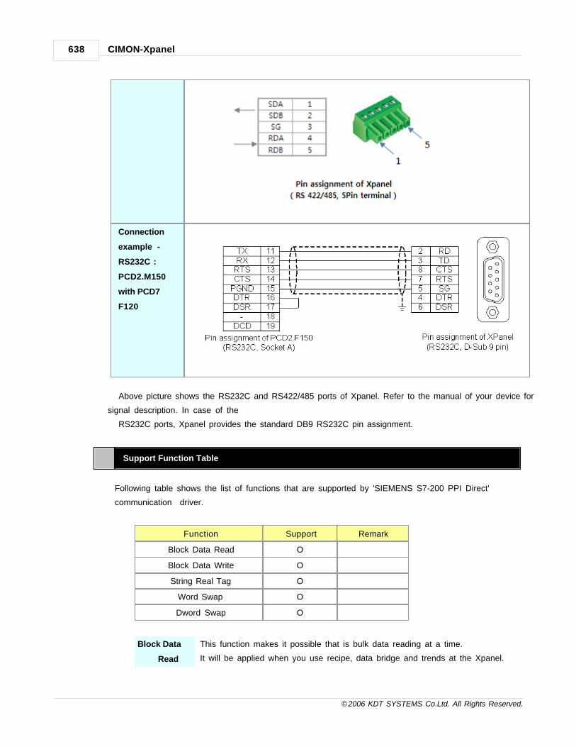
CIMON-Xpanel638
© 2006 KDT SYSTEMS Co.Ltd. All Rights Reserved.
Connection
example -
RS232C :
PCD2.M150
with PCD7
F120
Above picture shows the RS232C and RS422/485 ports of Xpanel. Refer to the manual of your device for
signal description. In case of the
RS232C ports, Xpanel provides the standard DB9 RS232C pin assignment.
Support Function Table
Following table shows the list of functions that are supported by 'SIEMENS S7-200 PPI Direct'
communication driver.
Function Support Remark
Block Data Read O
Block Data Write O
String Real Tag O
Word Swap O
Dword Swap O
Block Data
Read
This function makes it possible that is bulk data reading at a time.
It will be applied when you use recipe, data bridge and trends at the Xpanel.

Communication Driver 639
© 2006 KDT SYSTEMS Co.Ltd. All Rights Reserved.
Block Data
Write
This function makes it possible that is bulk data writing at a time.
It will be applied when you use recipe, data bridge and trends at the Xpanel.
String Real
Tag
It makes the device as the serialized memory so you can communicate string data
of Xpanel with PLC.
Word Swap This function swaps bytes of all word or double work sized data. It depends upon
16Bit Data Swap configuration.
Dword Swap This function swaps word of all double word sized data. It depends upon 32Bit Data
Swap configuration.
27.40 SICK RFID Reader Enet
This driver provides the function of ethernet communication with SICK RFID Reader(RFH620
model).
Communication Setup : Xpanel
Create a newDevice For creating a new device activate the menu ‘Tools’- >’I/O Devices’ or icon in tool-bar.
Following picture shows the first step of creating a new device.

CIMON-Xpanel640
© 2006 KDT SYSTEMS Co.Ltd. All Rights Reserved.
I/O Device Name : Write device name. This name will be used with Station name
when you register tags in Database.
Select a devicetype
I/O Device type : " SICK RFID Reader Enet "
After selecting the ‘OK’ button of previous step,
Select “SICK RFID Reader Enet” and set up as following.
Set up configuration as below• Device Type : SICK RFID Reader Enet• Protocol : TCP• Time Out : 15 ~ 30 (Delay time of response frame. You can select it
from 15 to 30) Retry No. : 1 (To avoid sending the same frame, it must be 1.)
Create a station Move to the ‘Station’ tab of ‘Ethernet Communication Configuration’ dialog box.
In this dialog box, all the connected PLC stations can be configured and registered to the
XPanel.
Each field can be configured with following rules.

Communication Driver 641
© 2006 KDT SYSTEMS Co.Ltd. All Rights Reserved.
Station Name Give a name to the PLC. This name will be used in the database
window accompanied with the ‘Device Name’.
Station Type Select the “RFH620”.
Network ID No effect
IP Address Write IP address of RFID Reader.
Socket Port No 2112 is default value. (It is subject to change according toReader’s type.)
16Bit DataSwap
No effect
32Bit DataSwap
No effect
UsingChecksum
No effect
Comm.ErrorMessage PopUp
No effect
Address & Function Codes
Memory address is as following.

CIMON-Xpanel642
© 2006 KDT SYSTEMS Co.Ltd. All Rights Reserved.
Devicename
Tag type W/R Address Description
D AnalogString
W/R D0 ~ D255 - It is used to indicate value ofRFID Tag.
- The Block size is 4Byte and itcan save 4words or 4Byte data.
- If you write value to D devicetag, It will read and displaydata as tag size.
W AnalogString
W W0 ~ W255 - It is used to change the valueof RFID Tag.
- Only writing is possible andthere is no status value.
- Size must be setup by 4ByteEx) Analog Tag
UINT32, INT32, Float andetc.
String TagLength of String: 4, 8, 12,
16..- If you write value to ‘W’ devicetag, it change value of RFID Tagas tag data size.
S Analog W/R S0 - It is used to indicate finalcommunication status.40 : Time out (No response)Otherwise is error of Reader(Refer to Reader’s manual)
- UIN8 is used as Data type.
D : It is used to read code which is saved in RFID Tag. It can save by block and 4Byte is savedin a Block. writing tag value runs, it read RFID Tag and update tag value.Refer to below String.
- String starting with “I”: Initialize connected TCP Socket.- String starting with “D”: Initialize communication status and received Tag data.
W : It is used to change code value which is saved in RFID Tag. It can be used by 4Byte andonly writing is possible.S : It is used to check final communication status. Data type is UINT8.
Ex 1) In case that you want to read the saved 16 words starting from Block 0 of RFID Tag1. Register 16 length string real tag to Database.
A. String Real TagB. IO address : D00C. Length Of String: 16

Communication Driver 643
© 2006 KDT SYSTEMS Co.Ltd. All Rights Reserved.
2. Write tag value to String Real tag that you just registered above as you readvalue.A. In case that the tag name is “STR_00” that you registered as String Real TagB. STR_00 = “”;C. Assign estimated value because there is no writing value at Step B.D. Communication result will display if “S00” tag is registered in IO address.
Ex 2) In case that you want to re-write 16 length string from Block 0 to 3 of RFID Tag.1. Register 16 length string real tag to Database.
A. String Real TagB. IO address : W00C. Length Of String : 16
2. Write tag value to String Real tag as you write value.A. In case that the tag name is “WSTR_00” that you registered as String Real
TagB. WSTR_00 = “ABCDER1234567890”;C. Input String will be saved by 4 from Block 0.
- Block 0 : “ABCD”- Block 1 : “ER12”- Block 2 : “3456”- Block 3 : “7890”
D. If string is over 16, only 16 string is saved.E. If string is less than 16, least number is initialized to 0.
Reader Setup
(1) Install “SOPAS engineering Tool”Download “SOPAS engineering Tool” from SICK homepage and install it.
(2) Run “SOPAS Single Device”Open “SOPAS Single Device” program.
(3) Connect deviceConnect Reader by nell modem cable and then click “Search connected devices”

CIMON-Xpanel644
© 2006 KDT SYSTEMS Co.Ltd. All Rights Reserved.
Select “RFH620” and click the “Next” in Connection Wizard window.
Select ‘Standard Protocol’ and click ‘Configure interface’

Communication Driver 645
© 2006 KDT SYSTEMS Co.Ltd. All Rights Reserved.
Select COM port and use standard setup of ‘Advanced Tab’

CIMON-Xpanel646
© 2006 KDT SYSTEMS Co.Ltd. All Rights Reserved.
Click ‘OK’ to finish Configure interface setup and then click ‘Next’ to move next step. It starts to find out Com port and display result on ‘Found Device’
Select found device and click ‘Next’ to upload.

Communication Driver 647
© 2006 KDT SYSTEMS Co.Ltd. All Rights Reserved.
Device setup is displayed after uploading.

CIMON-Xpanel648
© 2006 KDT SYSTEMS Co.Ltd. All Rights Reserved.
Move to ‘Ethernet’ tap and setup IP Address and Subnet Mask. Reboot button is activated after setup. The changed setup is affected if you reboot.
Protocol/Output Format : Output Format #1Server/Client : ServerIP-Port : 2112 (In case that you change port number, go to Xpanel Designer IO Deviceand change Socket Port No. in Station.)
Communication Cable Wiring
27.41 SIEMENS RK512/3964R
This driver provides the software interface and communication protocol between Xpanel and Siemens
Simatic PLC (S5 and S7).
It supports the following families of Siemens Simatic S5 system.
· S5 : CPU 115U, 135U or 150U via communication card CP524 or CP525.

Communication Driver 649
© 2006 KDT SYSTEMS Co.Ltd. All Rights Reserved.
· S7 : CPU 315-2 via the communication card CP341-1
· S7 : CPU 412-1 via the communication card CP441-2
Communication Setup : PLC
This section describes how to set up the Siemens Simatic hardware. Use the information in this section in
conjunction with the Siemens publications associated with your PLC system.
The physical communication layer is performed via a serial RS232C link connected to a Siemens CP524 or
CP525 communication card.
The Siemens Simatic S5 system must contain a S5 unit of one of the following types : S5-115u, S5-135u,
S5-150u.
The communication protocol 3964R must be loaded into the CP525 module, and the CPU must be loaded
with the following Siemens
Function Blocks (FB) : Synchron, Send, Receive.
These system function blocks are used to establish the communication between the CPU and the CP525.
Depending on which type of CPU you use, different function blocks are required.
115U 135U 150U
Synchron FB249 FB125 FB185
Send FB244 FB120 FB180
Receive FB245 FB121 FB181
Communication Setup : Xpanel
Createa newDevice
For creating a new device activate the menu ‘Tools’ -> ’I/O Devices’ or icon in tool-bar.
Following picture shows the first step of creating a new device.

CIMON-Xpanel650
© 2006 KDT SYSTEMS Co.Ltd. All Rights Reserved.
I/O Device Name : Give a device name. This name will be used in the TAG configuration window of
database
accompanied by the ‘Station Name’.
Selectadevicetype
I/O Device type : ' SIEMENS RK512/3964R '
After selecting the ‘OK’ button of previous step, ‘Serial Communication Configuration’ dialog box
will be popped up as shown in following picture.
In this window, select the ‘Device Type’ as ‘SIEMENS RK512/3964R’ and configure the proper serial
communication parameters.

Communication Driver 651
© 2006 KDT SYSTEMS Co.Ltd. All Rights Reserved.
Createastation
Move to the ‘Station’ tab of ‘Serial Communication Configuration’ dialog box.
In this dialog box, all the connected PLC stations can be configured and registered to the Xpanel. Each
field can be configured with following rules.

CIMON-Xpanel652
© 2006 KDT SYSTEMS Co.Ltd. All Rights Reserved.
Station Name Give a name to the PLC. This name will be used in the database window
accompanied with the ‘Device Name’.
Station Type Choose the ‘SIEMENS’. (No other type can be selected.)
Network ID This field has no effect.
Station No. This field has no effect.
RK512/3964(R) protocol has no station number. It is based on 1:1
communication environment.
16Bit Data
Swap
This option swaps bytes of all word or double word sized data. Following
diagram shows an example of byte swapping.
Almost all of the data type will be influenced by this option except INT8 /

Communication Driver 653
© 2006 KDT SYSTEMS Co.Ltd. All Rights Reserved.
UINT8 / BCD8 / UBCD8.
32Bit Data
Swap
This option swaps words of all double word sized data. Following diagram shows
an example of word swapping.
INT32 / UINT32 / BCD32 / UBCD32 / FLOAT type of TAG values will be
influenced by this option.
Using
Checksum
When the 3964R procedure was used, this option must be checked. Otherwise,
Xpanel uses 3964 procedure.
Comm. Error
Message pop
Up
If this item is checked, Xpanel displays a communication error notification
message at every Rx and Tx error.
Otherwise(unchecked), Xpanel does not display the message at data receive
error. Only when there is data transmit (writing a TAG value to the station)
error, the notification message is popped up. This message box will be closed
automatically about 5 seconds after.
Address Notation
The address of TAG in Xpanel has the following format
TAG Type Format Example
Analog [Symbol][DB Number]:[DW number] D10:1
Digital [Symbol][DB Number]:[DW number].[Bit Number] I:12.7
· DB Number : decimal number (0..255)
· DW number : decimal number (0..255)
· Bit Number : hexa-decimal number (0..F)
Symbol Area Example DB DW Type Access
D Data Block D1:120, D1:12.F 0-255 0-255 Word R/W
X Ext. Data Block X2:003, X2:3.F 0-255 0-255 Word R/W
F Flags F:12, F:12.7 - 0-255 BYTE R
I Inputs I:008, I:008.7 - 0-127 BYTE R
Q Outputs Q:004, Q:004.7 - 0-127 BYTE R

CIMON-Xpanel654
© 2006 KDT SYSTEMS Co.Ltd. All Rights Reserved.
27.42 SIEMENS S7 Ethernet
This driver provides the software interface and communication protocol between Xpanel and Siemens
Simatic S7 PLCs.
It supports the following families of Siemens Simatic S7 system.
· S7-300 CPU via the communication card CP343-1 IT
· S7-400 CPU via the communication card CP443-1 IT
Communication Setup : Xpanel
Createa newDevice
For creating a new device activate the menu ‘Tools’- >’I/O Devices’ or icon in tool-bar.
Following picture shows the first step of creating a new device.
I/O Device Name : Give a device name. This name will be used in the TAG configuration window of database
accompanied by the ‘Station Name’.
Selecta
I/O Device type : ' SIEMENS S7 Ethernet '

Communication Driver 655
© 2006 KDT SYSTEMS Co.Ltd. All Rights Reserved.
devicetype
After selecting the ‘OK’ button of previous step, ‘Ethernet Communication Configuration’ dialog box will be
popped up as shown in following picture.
In this window, select the ‘Device Type’ as ‘SIEMENS S7 Ethernet’ and ‘TCP’ protocol.
This driver supports only TCP/IP protocol stack.
Createastation
Move to the ‘Station’ tab of ‘Ethernet Communication Configuration’ dialog box.
In this dialog box, all the connected PLC stations can be configured and registered to the Xpanel.
Each fields can be configured with following rules.
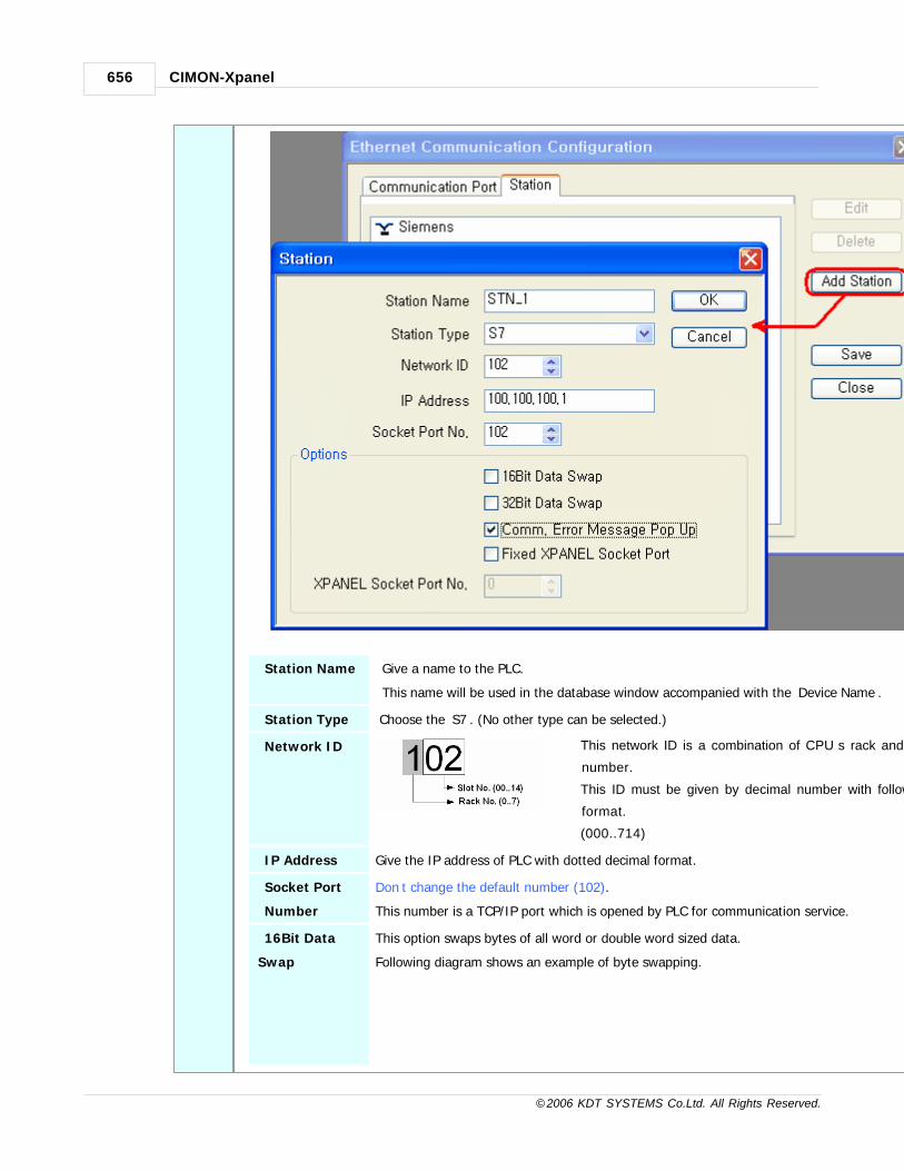
CIMON-Xpanel656
© 2006 KDT SYSTEMS Co.Ltd. All Rights Reserved.
Station Name Give a name to the PLC.
This name will be used in the database window accompanied with the ‘Device Name’.
Station Type Choose the ‘S7’. (No other type can be selected.)
Network ID This network ID is a combination of CPU’s rack and slot
number.
This ID must be given by decimal number with following
format.
(000..714)
IP Address Give the IP address of PLC with dotted decimal format.
Socket Port
Number
Don’t change the default number (102).
This number is a TCP/IP port which is opened by PLC for communication service.
16Bit Data
Swap
This option swaps bytes of all word or double word sized data.
Following diagram shows an example of byte swapping.

Communication Driver 657
© 2006 KDT SYSTEMS Co.Ltd. All Rights Reserved.
Almost all of the data type will be influenced by this option except INT8 / UINT8 / BCD8 /
UBCD8.
32Bit Data
Swap
This option swaps words of all double word sized data.
Following diagram shows an example of word swapping.
INT32 / UINT32 / BCD32 / UBCD32 / FLOAT type of TAG values will be influenced by this
option.
Fixed Xpanel
Socket Port /
Xpanel Socket
Port No.
If this option was checked, Xpanel will use only one port defined in "Xpanel Socket Port No."
field for connection with PLC. Otherwise, Xpanelwill change the port at every TCP connection
or communication error.
This option is provided for Xpanel to deal with various TCP port management ways of PLC.
Some PLC has a limit on the number of TCP services. In that case, this option can be a help.
The actual effect of this option on PLC cannot be described here. Because, there are too many
kinds of PLC and the response in PLC is entirely dependant on the specification of PLC and
engineer’s experience. The default setting of this option is unchecked state.
Comm. Error
Message pop
Up
If this item is checked, Xpanel displays a communication error notification message at every Rx
and Tx error.
Otherwise(unchecked), Xpanel does not display the message at data receive error. Only when
there is data transmit (writing a TAG value to the station) error, the notification message is
popped up. This message box will be closed automatically about 5 seconds after.
Address Notation
The address of TAG in Xpanel has the following format.
TAG Type Format Example
Analog [Symbol][DB Number,][Address] DB1,1
Digital [Symbol][DB Number,][Address].[Bit Number] DB1,2.7
· DB Number, : decimal number (0..65535) followed by comma (,). It is used in data block (DB) addressing
only.
For other types of memory, this field must be omitted.

CIMON-Xpanel658
© 2006 KDT SYSTEMS Co.Ltd. All Rights Reserved.
· Address : decimal number (0..65535)
· Bit Number : decimal number (0..7)
Following table shows the list of devices which can be referenced in Xpanel database.
Symbol Description Word Notation Bit Notation Type Access
PI Peripheral Input PI001 PI001.7 Analog/Digital R/W
I Input I002 I002.7 Analog/Digital R/W
Q Output Q003 Q003.7 Analog/Digital R/W
M Memory M004 M004.7 Analog/Digital R/W
DB Data Block DB01,01 DB01,01.7 Analog/Digital R/W
T Timer T005 - Analog R
C Counter C006 - Analog R
The device T and C (timer and counter) must be defined as UBCD16 typed TAG for normal data
manipulation.
Following picture shows the data type configuration window of Xpanel database.
Communication Cable Wiring
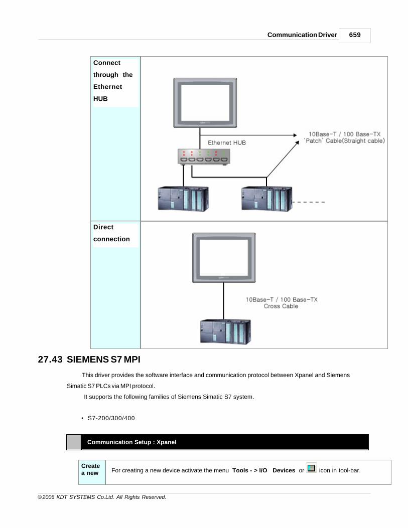
Communication Driver 659
© 2006 KDT SYSTEMS Co.Ltd. All Rights Reserved.
Connect
through the
Ethernet
HUB
Direct
connection
27.43 SIEMENS S7 MPI
This driver provides the software interface and communication protocol between Xpanel and Siemens
Simatic S7 PLCs via MPI protocol.
It supports the following families of Siemens Simatic S7 system.
· S7-200/300/400
Communication Setup : Xpanel
Createa new For creating a new device activate the menu ‘Tools’- >’I/O Devices’ or icon in tool-bar.

CIMON-Xpanel660
© 2006 KDT SYSTEMS Co.Ltd. All Rights Reserved.
Device Following picture shows the first step of creating a new device.
I/O Device Name : Give a device name. This name will be used in the TAG configuration window of
database
accompanied by the ‘Station Name’.
Selectadevicetype
I/O Device type : ' SIEMENS S7 MPI '
After selecting the ‘OK’ button of previous step, ‘Serial Communication Configuration’ dialog box
will be popped up as
shown in following picture.

Communication Driver 661
© 2006 KDT SYSTEMS Co.Ltd. All Rights Reserved.
In this window, select the ‘Device Type’ as ‘SIEMENS S7 MPI’ and appropriate communication
parameters.
Those parameters must be matched with the PLC.
Loca
l
I D
Give a station (node) number of Xpanel. This number does not duplicated with the one of
PLC. The node number can be the integer value between 0 and 126.
Net
wo
rk
Op
Designate the maximum station (node) number of connected network. This can be one of
following numbers. If the Xpanel is the unique master in network, the integer value of
(1,000+maximum station number) should be designated.

CIMON-Xpanel662
© 2006 KDT SYSTEMS Co.Ltd. All Rights Reserved.
t
Createastation
Move to the ‘Station’ tab of ‘Serial Communication Configuration’ dialog box. In this dialog box, all the
connected PLC
stations can be configured and registered to the Xpanel. Each field can be configured with following
rules.

Communication Driver 663
© 2006 KDT SYSTEMS Co.Ltd. All Rights Reserved.
Station Name Give a name to the PLC.
This name will be used in the database window accompanied with the ‘Device
Name’.
Station Type Choose the ‘S7 MPI’. (No other type can be selected.)
Network ID This field has no meaning in this driver. (ignored in runtime)
Station No Specify a decimal number between 0 and 126.
16Bit Data
Swap
This option swaps bytes of all word or double word sized data.
Following diagram shows an example of byte swapping.
Almost all of the data type will be influenced by this option except INT8 / UINT8 /
BCD8 / UBCD8.
32Bit Data
Swap
This option swaps words of all double word sized data.
Following diagram shows an example of word swapping.
INT32 / UINT32 / BCD32 / UBCD32 / FLOAT type of TAG values will be influenced
by this option.
Using
Checksu
m
This field has no effect.
Comm. Error
Message pop
Up
If this item is checked, Xpanel displays a communication error notification
message at every Rx and Tx error.Otherwise(unchecked), Xpanel does not
display the message at data receive error. Only when there is data transmit
(writing a TAG value to the station) error, the notification message is popped up.
This message box will be closed automatically about 5 seconds after.
Address Notation
The address of TAG in Xpanel has the following format.

CIMON-Xpanel664
© 2006 KDT SYSTEMS Co.Ltd. All Rights Reserved.
TAG Type Format Example
Analog [Symbol][DB Number,][Address] DB1,1
Digital [Symbol][DB Number,][Address].[Bit Number] DB1,2.7
· DB Number, : decimal number (0..65535) followed by comma (,). It is used in data block (DB)
addressing only.
For other types of memory, this field must be omitted.
· Address : decimal number (0..65535)
· Bit Number : decimal number (0..7)
Following table shows the list of devices which can be referenced in Xpanel database.
Symbol Description Word Notation Bit Notation Type Access
PI Peripheral Input PI001 PI001.7 Analog/Digital R/W
I Input I002 I002.7 Analog/Digital R/W
Q Output Q003 Q003.7 Analog/Digital R/W
M Memory M004 M004.7 Analog/Digital R/W
DB Data Block DB01,01 DB01,01.7 Analog/Digital R/W
T Timer T005 - Analog R
C Counter C006 - Analog R
The device T and C (timer and counter) must be defined as UBCD16 typed TAG for normal data
manipulation.
Following picture shows the data type configuration window of Xpanel database.

Communication Driver 665
© 2006 KDT SYSTEMS Co.Ltd. All Rights Reserved.
Communication Cable Wiring
SSW7 Adapter
The cable supplied with the adapter can be directly connected to the Xpanel
without any change.
If there is some need to make the cable by yourself, refer to the following picture..
27.44 SIEMENS S7 PPI Direct
This driver provides the software interface and communication protocol between Xpanel and SIEMENS
SIMATIC S7-200 PLCs via PPI protocol.

CIMON-Xpanel666
© 2006 KDT SYSTEMS Co.Ltd. All Rights Reserved.
Communication Setup : Xpanel
Createa newDevice
For creating a new device activate the menu ‘Tools’- >’I/O Devices’ or icon in tool-bar.
Following picture shows the first step of creating a new device.
I/O Device Name : Give a device name. This name will be used in the TAG configuration window of database
accompanied by the ‘Station Name’.
Selectadevicetype
I/O Device type : ' SIEMENS S7 PPI DirectI '
After selecting the 'OK' button of previous step, ‘Serial communication Configuration’ dialog box will be
popped up as
shown in following picture.

Communication Driver 667
© 2006 KDT SYSTEMS Co.Ltd. All Rights Reserved.
In this window, select the 'Device Type' as ‘SIEMENS S7 PPI Direct’ and appropriate communication
parameters.
Those parameters must be matched with the PLC. Communication parameters should be configured as
shown
in the following table.
Baud Rate 9600 or 19200 (must be matched with the one of PLC)
Parity Even
Data Bits 8 Bits

CIMON-Xpanel668
© 2006 KDT SYSTEMS Co.Ltd. All Rights Reserved.
Stop Bits 1 Bit
Comm.Type RS485
Local ID The Xpanel occupies the station ID '0' (zero) for its network address.
This Xpanel's address is fixed and cannot be changed.
Createastation
Move to the ‘Station’ tab of 'Serial Communication Configuration' dialog box. In this dialog box, all the connected
PLC
stations can be configured and registered to the Xpanel. Each field can be configured with following rules.

Communication Driver 669
© 2006 KDT SYSTEMS Co.Ltd. All Rights Reserved.
Station Name Give a name to the PLC.
This name will be used in the database window accompanied with the ‘Device Name’.
Station Type Choose the ‘S7’. (No other type can be selected.)
Network ID This field has no meaning in this driver. (ignored in runtime)
Station No Specify a decimal number between 0 and 126.
16Bit Data Swap This option swaps bytes of all word or double word sized data.
Following diagram shows an example of byte swapping.
Almost all of the data type will be influenced by this option except INT8 / UINT8 / BCD8 /
UBCD8.
32Bit Data Swap This option swaps words of all double word sized data.
Following diagram shows an example of word swapping.
INT32 / UINT32 / BCD32 / UBCD32 / FLOAT type of TAG values will be influenced by this
option.
Using Checksum This field has no effect.
Comm. Error
Message pop Up If this item is checked, Xpanel displays a communication error notification message at
every Rx and Tx error.Otherwise(unchecked), Xpanel does not display the message at
data receive error. Only when there is data transmit (writing a TAG value to the station)
error, the notification message is popped up. This message box will be closed
automatically about 5 seconds after.
Communication Setup : S7-200
Following picture shows the screen shot of STEP 7-Micro/Win.
The network address and communication speed (Baud rate) of PLC are configured in this dialog box.

CIMON-Xpanel670
© 2006 KDT SYSTEMS Co.Ltd. All Rights Reserved.
Please note that those set data should be matched with the device configuration of Xpanel.
Address Notation
The address of TAG in Xpanel has the following format
TAG Type Format Example
Analog [Symbol][Address] VW064
Digital [Symbol][Address].[Bit Number] or[Symbol][Address][Bit Number]
M012.3 orM0123
· Address : decimal number (0..65535)
· Bit Number : decimal number (0..7)
Following table shows the list of devices which can be referenced in Xpanel database.
Symbol Description Word Notation Bit Notation Type Access
I Input - I7.7 Digital R
Q Output - Q7.7 Digital R/W
M Internal Memory - M31.7 Digital R/W
SM Special Memory - SM85.7 Digital R/W
T Timer - T127 Digital R
C Counter - C127 Digital R

Communication Driver 671
© 2006 KDT SYSTEMS Co.Ltd. All Rights Reserved.
IW Input IW7 - Analog R
QW Output QW7 - Analog R/W
MW Internal Memory MW31 - Analog R/W
SMW Special Memory SMW85 - Analog R/W
VW Variable Memory VW4095 - Analog R/W
TW Timer SV TW127 - Analog R
CW Counter SV CW127 - Analog R
Communication Cable Wiring
Support Function Table
Following table shows the list of functions that are supported by 'SIEMENS S7-200 PPI Direct'
communication driver.
Function Support Remark
Block Data Read O
Block Data Write O
String Real Tag O
Word Swap O
Dword Swap O
Block Data
Read
This function makes it possible that is bulk data reading at a time.
It will be applied when you use recipe, data bridge and trends at the Xpanel.

CIMON-Xpanel672
© 2006 KDT SYSTEMS Co.Ltd. All Rights Reserved.
Block Data
Write
This function makes it possible that is bulk data writing at a time.
It will be applied when you use recipe, data bridge and trends at the Xpanel.
String Real Tag It makes the device as the serialized memory so you can communicate string data of Xpanel
with PLC.
Word Swap This function swaps bytes of all word or double work sized data. It depends upon 16Bit Data
Swap configuration.
Dword Swap This function swaps word of all double word sized data. It depends upon 32Bit Data Swap
configuration.
27.45 YOKOGAWA Personal Computer Link
This Manual explains about the method of CIMON-Xpanel communication with YOKOGAWA PLC using
RS232C or RS422/485.
Communication Setup : Xpanel
You can configure I/O device according to various kind of field equipments by using Xpanel Designer.
Configure the option of the example followed. More details about I/O device configuration in section “I/O
device configuration”.
Createa newDevice
To configure the communication device of YOKOGAWA PLC, Select 'Tools' - 'I/O device' in
the menu or icon in
tool-bar, and then “I/O device configuration” dialog box will be shown up. And then click [new
device] button.
“I/O device selection” dialog box is shown up, select a device name and a device type as the
following figure.

Communication Driver 673
© 2006 KDT SYSTEMS Co.Ltd. All Rights Reserved.
I/O Device Name : Give a device name. This name will be used in the TAG configuration
window of database
accompanied by the ‘Station Name’.
Selectadevicetype
I/O Device type : ' YOKOGAWA Computer Link Protocol '
You can select communication device which is connected to Xpanel.

CIMON-Xpanel674
© 2006 KDT SYSTEMS Co.Ltd. All Rights Reserved.
Comm.Port COM1
Select communication port to communicate. If you use RS-422/485, you
must select “COM1”.
When RS-232 communication type of COM1 port is used, 9P DSUB
connector is used.
And When RS-422/485 communication type of COM1 port is used, 5P plug
connector is used.
If you use COM1 port, you cannot use RS-232 and RS-422/485 together,
but you can use only one type.
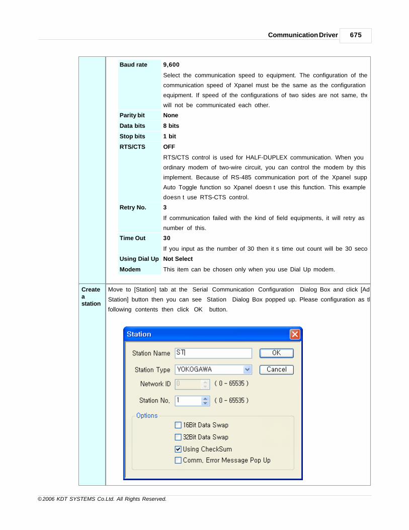
Communication Driver 675
© 2006 KDT SYSTEMS Co.Ltd. All Rights Reserved.
Baud rate 9,600
Select the communication speed to equipment. The configuration of the
communication speed of Xpanel must be the same as the configuration of
equipment. If speed of the configurations of two sides are not same, they
will not be communicated each other.
Parity bit None
Data bits 8 bits
Stop bits 1 bit
RTS/CTS OFF
RTS/CTS control is used for HALF-DUPLEX communication. When you
ordinary modem of two-wire circuit, you can control the modem by this
implement. Because of RS-485 communication port of the Xpanel supports
Auto Toggle function so Xpanel doesn’t use this function. This example
doesn’t use RTS-CTS control.
Retry No. 3
If communication failed with the kind of field equipments, it will retry as the
number of this.
Time Out 30
If you input as the number of 30 then it’s time out count will be 30 seconds.
Using Dial Up
Modem
Not Select
This item can be chosen only when you use Dial Up modem.
Createastation
Move to [Station] tab at the “Serial Communication Configuration” Dialog Box and click [Add
Station] button then you can see “Station” Dialog Box popped up. Please configuration as the
following contents then click “OK” button.

CIMON-Xpanel676
© 2006 KDT SYSTEMS Co.Ltd. All Rights Reserved.
Station Name ST
When field equipments number exceed over than 2, station name is used
for division of field equipment at the internal Xpanel.
Internal Xpanel it expresses as “Device.Station” and this example shows
you as “DEV.ST” .
Station Type DirectNet
Network ID This field has no effect.
Station No 1
When field equipments number exceed over than 2, it assigned different
Station No. to divide. Station number must be same configured in field
equipments. It will not be communicated if the Station No. different each
other.
16Bit Data
Swap
This field has no effect.
32Bit Data
Swap
This field has no effect.
Using
Checks
um
This field has no effect.
Comm. Error
Message pop
Up
If this item is checked, Xpanel displays a communication error notification
message at every Rx and Tx error.Otherwise(unchecked), Xpanel does
not display the message at data receive error. Only when there is data
transmit (writing a TAG value to the station) error, the notification
message is popped up. This message box will be closed automatically
about 5 seconds after.
Module Configuration
TransmissionSp
Remove side tab of Personal Computer Link Module and then configure Baud Rate with SW1.
The baud rate must be same as the speed which was configured in “Serial Communication
Configuration”.

Communication Driver 677
© 2006 KDT SYSTEMS Co.Ltd. All Rights Reserved.
eedSwitch :SW1
mode Baud rate (bps)
0 300
1 600
2 1200
3 2400
4 4800
5 9600
6 19200
The baud rate is set as 9600 bps by selecting Mode 5 in configuration in this example.
DataFormatSwitch:SW2
You can configure about the communication in this switch.
This configuration must be same which was configured in “Serial Communication Configuration”.
No. Function OFF ON
1 Data Length 7 bits 8 bits
2 Parity None Yes
3 Odd parity Even Parity
4 Stop Bit 1 bit 2 bits
5 Check Sum None Yes
6 Termination Char None Yes
7 Protection None Yes
8
Data Length 8 bits
Parity None
Stop Bit 1bit
Check Sum Yes
Check sum will be used to protect communication data safely from the
transmission error.
Termination Char Yes (Attach <CR> at the end of the frame.)
Protection None
Wiring Diagram
You can wire communication cable as the following figures.

CIMON-Xpanel678
© 2006 KDT SYSTEMS Co.Ltd. All Rights Reserved.
RS-232C : Null Modem
Xpanel connects three lines to PLC. PLC connects lines such as above figure. If you
don’t connect lines
to PLC as the showing figure, it can’t transmit data to other field equipments but can
receive data so that
not to be accomplished communication.
RS-422
On wiring as the above figure terminal resistance must be 330Ω.
To improve stability of communication it should connect SG and use STP cable.
But shielded cables must be earthed.
RS-485
On wiring as above the figure terminal resistance must be 120Ω.

Communication Driver 679
© 2006 KDT SYSTEMS Co.Ltd. All Rights Reserved.
When Xpanel is using RS-485, it connected with SDA and SDB but disconnect with
RDA and RDB.
To improve stability of communication it should connect SG and use STP cable.
But shielded cables must be earthed.
Device Memory range
You can use device memories as following range.
Device Sym F3SP20 /F3SA20
F3SP30 /F3SA30
F3SP21 F3SP25 F3SP35
Input X X00201 X61364 X00201 X61364 X00201 X71364 X00201 X71364 X00201 X71364
Output Y Y00201 Y61364 Y00201 Y61364 Y00201 Y71364 Y00201 Y71364 Y00201 Y71364
Internal I I00001 I04096 I00001 I08192 I00001 I04096 I00001 I08192 I00001 I16384
common E E00001 E02048 E00001 E02048 E00001 E02048 E00001 E04096 E00001 E04096
Link L L00001 L01024 L00001 L01024 L00001 L11024 L00001 L71024 L00001 L71024
Special M M00001 M00512 M00001 M00512 M00001 M02048 M00001 M09984 M00001 M09984
Data D D00001 D05120 D00001 D08192 D00001 D05120 D00001 D08192 D00001 D08192
File B - - - B00001 B32768 B00001 B32768
Link W W00001 W01024
W00001 W01024
W00001 W11024
W00001 W71024 W00001 W71024
Special Z Z00001 Z00256 Z00001 Z00256 Z00001 Z00512 Z00001 Z00512 Z00001 Z00512
Index V V00001 V00016 V00001 V00016 V00001 V00032 V00001 V00032 V00001 V00032
Common R R00001 R01024 R00001 R01024 R00001 R01024 R00001 R04096 R00001 R04096
Timer T TU0001 TU0256 TU0001 TU1024 TU0001 TU0256 TU0001 TU1024 TU0001 TU2048
TP0001 TP0256 TP0001 TP1024 TP0001 TP0256 TP0001 TP1024 TP0001 TP2048
TI0001 TI0256 TI0001 TI1024 TI0001 TI0256 TI0001 TI1024 TI0001 TI2048
TS0001 TS0256 TS0001 TS1024 TS0001 TS0256 TS0001 TS1024 TS0001 TS2048
Counter C CU0001 CU0256
CU0001 CU1024 CU0001 CU0256 CU0001 CU1024 CU0001 CU1024
CP0001 CP0256 CP0001 CP1024 CP0001 CP0256 CP0001 CP1024 CP0001 CP1024
CI0001 CI0256 CI0001 CI1024 CI0001 CI0256 CI0001 CI1024 CI0001 CI1024
CS0001 CS0256 CS0001 CS1024 CS0001 CS0256 CS0001 CS1024 CS0001 CS1024
Error Code
When Xpanel communicates with PLC it can receive NAK including error code.
Reference Error code contents as following table.

CIMON-Xpanel680
© 2006 KDT SYSTEMS Co.Ltd. All Rights Reserved.
Error Code(EC1)
Semantics Probable causes
01 CPU number Error CPU number is out of allowable value which range is 1~4.
02 Command Error No command. It can’t execute command
03 Device Specification Error No device. It doesn’t adequate use of WORD in the bit device.
04 Value outside the setting range When you write a Bit Value, you must use only 0 or 1.
While you write Word, it is out of 0000~FFFF.
05 Data count out of range The number of Bit/Word exceeded permitted range.
The number of data or device parameter is not same.
06 Monitor Error Monitor operates without BRS/WRS.
07 CPU Type Error It is not Basic CPU.
08 Parameter Error If it is not specified parameter by this time, it will be invalidated.
41 Communication Error Error occurred while it communicated.
42 Checksum Error Checksum dislike each other.
43 Internal Buffer Overflow Receiving data is over than allowable number.
44 Timeout while receiving characters ETX data receiving fail. Timeout is 5 seconds.
27.46 Fuji Micrex SX Ethernet
This document describes the Micrex SX Ethernet (Fuji Electric) communication driver for XPanel. This driver
supports the TCP/IP.
Supported communication modules of SX PLC are NP1L-ET1 and NP1L-ET2.
Communication Setup : Xpanel
Createa newDevice
For creating a new device activate the menu ‘Tools’- >’I/O Devices’ or icon in tool-bar.
Following picture shows the first step of creating a new device.

Communication Driver 681
© 2006 KDT SYSTEMS Co.Ltd. All Rights Reserved.
I/O Device Name : Give a device name. This name will be used in the TAG configuration
window of database
accompanied by the ‘Station Name’.
Selectadevicetype
I/O Device type : " FUJI Micrex SX "
After selecting the ‘OK’ button of previous step,
‘Ethernet Communication Configuration’ dialog box will be popped up as shown in following
picture.

CIMON-Xpanel682
© 2006 KDT SYSTEMS Co.Ltd. All Rights Reserved.
In this window, select the ‘Device Type’ as ‘FUJI Micrex SX’ and configure the proper Ethernet
communication parameters.
Take note that the FUJI Micrex SX driver supports TCP/IP protocol stack only.
Since XPanel communicates with the PLC in ‘loader command communication mode’.
•Initialize the Tx Frame When Timeout Occurs
This option provides a safety solution for communication troubled situation. If this option was
checked
and there was a communication error, the system would delete the remaining control frames
(data transmit frames from XPanel to PLC)
which were not transmitted but queued in communication buffer of XPanel.
Createastation
Move to the ‘Station’ tab of ‘Ethernet Communication Configuration’ dialog box.
In this dialog box, all the connected PLC stations can be configured and registered to the
XPanel.
Each field can be configured with following rules.

Communication Driver 683
© 2006 KDT SYSTEMS Co.Ltd. All Rights Reserved.
StationName
Give a name to the PLC. This name will be used in the database window accompanied
with the ‘Device Name’.
StationType
Choose the type of connected PLC among the “NP1L-ETn”.
NetworkID
Be ignored in runtime.
SocketPortNo
The socket port number should be matched with the [reference number of local port
+251] or [reference number of local port+253]. The reference number of local port is
configured in DWin300 as shown in the following figure.

CIMON-Xpanel684
© 2006 KDT SYSTEMS Co.Ltd. All Rights Reserved.
In this example, the socket port number should be 507(256+251) or 509(256+253)
16BitDataSwap
No effect
32BitDataSwap
No effect
UsingChecksum
No effect
Comm.ErrorMessag
If this item is checked, XPanel displays a communication error notification message at
every Rx and Tx error.
Otherwise(unchecked), XPanel does not display the message at data receive error. Only
when there is data transmit (writing a TAG value to the station) error, the notification
message is popped up. This message box will be closed automatically about 5 seconds
after.

Communication Driver 685
© 2006 KDT SYSTEMS Co.Ltd. All Rights Reserved.
ePopUp
Address & Function Codes
Following table shows the list of valid address symbols and its usage examples. The symbol character has
to be placed in the first position of address string.
AddressFormat
TAG Type Format Example
Analog [Symbol][WordNo] %MW1.6 or %MD1.6
Digital [Symbol][WordNo][.][BitNo] %MW1.6.12 or %MX1.6.12
The ‘WordNo’ and ‘BitNo’ are represented by decimal number. (BitNo : 0..15)
SupportedSymbols
Symbol WordNo Range Description
%IX %IW %ID 0 512 Input
%QX %QW %QD 0 512 Output
%MX1. %MW1. %MD1. 0 131071 Standard Memory
%MX3. %MW3. %MD3. 0 32767 Retain Memory
%MX10. %MW10. %MD10. 0 511 System Memory
The memory areas listed above are provided for general purposes.
The actual range of each area should be checked with the manual of connected CPU type.
XPanel treats the word address (%?W_) and double word address (%?D_) as same.
addresses represent a single word memory.
The actual data type should be declared in the ‘Advance’ configuration tab in TAG database as shown in
the following picture.

CIMON-Xpanel686
© 2006 KDT SYSTEMS Co.Ltd. All Rights Reserved.
Communication Cable Wiring
This interface is satisfied with standard IEEE802.3 about the 10BaseT/100BaseTX.
You can make cable and allocation pin number of RJ45 as the following figure.
RJ45 Connector RJ45 Jack
Direct Cable: Host <-> HUB
Cable No Color Color No Cable
1 Orange/W Orange/W 1
2 Orange Orange 2
3 Green/W Green/W 3
4 Blue Blue 4
5 Blue/W Blue/W 5
6 Green Green 6
7 Brown/W Brown/W 7

Communication Driver 687
© 2006 KDT SYSTEMS Co.Ltd. All Rights Reserved.
8 Brown Brown 8
Crossover Cable: Host <-> Host
Cable No Color Color No Cable
1 Orange/W Green/W 1
2 Orange Green 2
3 Green/W Orange/W 3
4 Blue Blue 4
5 Blue/W Blue/W 5
6 Green Orange 6
7 Brown/W Brown/W 7
8 Brown Brown 8
Support Function Table
Following table shows the list of functions that are supported by 'SIEMENS S7-200 PPI Direct'
communication driver.
Function Support Remark
Block Data Read O
Block Data Write O
String Real Tag O
Word Swap O
Dword Swap O
Block Data
Read
This function makes it possible that is bulk data reading at a time.
It will be applied when you use recipe, data bridge and trends at the Xpanel.
Block Data
Write
This function makes it possible that is bulk data writing at a time.
It will be applied when you use recipe, data bridge and trends at the Xpanel.
String Real
Tag
It makes the device as the serialized memory so you can communicate string data
of Xpanel with PLC.
Word Swap This function swaps bytes of all word or double work sized data. It depends upon
16Bit Data Swap configuration.
Dword Swap This function swaps word of all double word sized data. It depends upon 32Bit Data
Swap configuration.

CIMON-Xpanel688
© 2006 KDT SYSTEMS Co.Ltd. All Rights Reserved.
27.47 ALLENBRADLEY DF1
This driver provides the software interface and communication protocao between XPanel and MicroLogix
PLCs.
Communication Setup : Xpanel
Create a newSetup For creating a new device activate the menu ‘Tools’- >’I/O Devices’ or icon in tool-bar.
Following picture shows the first step of creating a new device.
I/O Device Name : Give a device name.
This name will be used in the TAG configuration window of database accompanied by the
‘Station Name’.
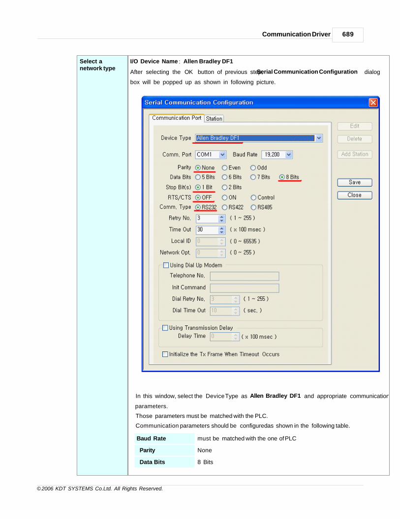
Communication Driver 689
© 2006 KDT SYSTEMS Co.Ltd. All Rights Reserved.
Select anetwork type
I/O Device Name : ‘Allen Bradley DF1’
After selecting the ‘OK’ button of previous step, ‘Serial Communication Configuration ’ dialog
box will be popped up as shown in following picture.
In this window, select the ‘Device Type’ as ‘Allen Bradley DF1’ and appropriate communication
parameters.
Those parameters must be matched with the PLC.
Communication parameters should be configured as shown in the following table.
Baud Rate must be matched with the one of PLC
Parity None
Data Bits 8 Bits

CIMON-Xpanel690
© 2006 KDT SYSTEMS Co.Ltd. All Rights Reserved.
Stop Bits 1Bits
Comm.Type RS232

Communication Driver 691
© 2006 KDT SYSTEMS Co.Ltd. All Rights Reserved.
Create a station Move to the ‘Station’ tab of ‘Serial Communication Configuration’ dialog box. In this dialog box, all
the connected
PLC stations can be configured and registered to the XPanel. Each field can be configured with
following rules.
Station Name Give a name to the PLC. This name will be used in the database window accompanied with the‘Device Name’.
Station Type Choose the ‘SLC500/MicroLogix’. (No other type can be selected.)
Network ID This field has no meaning in this driver. (ignored in runtime)
Station No. This number must be matched with the one of PLC.

CIMON-Xpanel692
© 2006 KDT SYSTEMS Co.Ltd. All Rights Reserved.
16Bit Data Swap This field has no meaning in this driver.
32Bit Data Swap This field has no meaning in this driver.
Using
Checksum
This field has no meaning in this driver.
Comm. Error
Message Pop
Up
If this item is checked, XPanel displays a communication error notification
message
at every Rx and Tx error.
Otherwise(unchecked), XPanel does not display the message at data
receive error.
Only when there is data transmit (writing a TAG value to the station) error,
the
notification message is popped up. This message box will be closed
automatically
about 5 seconds after.
Communication Setup : RSLogix
Following picture shows the screen shot of RSLogix. The network address and communication speed
(Baud Rate) of PLC are configured in this
dialog box. Error Detection must be selected to BCC and Driver is selected to Full Duplex.
Please note that those set data should be matched with the device configuration of XPanel.

Communication Driver 693
© 2006 KDT SYSTEMS Co.Ltd. All Rights Reserved.
Address Notation
Following table shows the list of devices which can be referenced in XPanel database.
Symbol Description Word Notation Bit Notation Access
I Input File I:00.000-I:08.255I:00.000/00-I:08.255/15
R/W
O Output File O:00.000-O:08.255 R/W
S Status File S:0-S163 M31.7 R/W
B Bit File B3:0-B3:255 SM85.7 R/W
T Timer File T4:0-T4:255 T127 R/W
C Counter File C5:0-C5:255 C127 R/W
N Integer File N7:0-N7:255 - R/W
F Float File F8:0-F8:255 - R/W

CIMON-Xpanel694
© 2006 KDT SYSTEMS Co.Ltd. All Rights Reserved.
Communication Cable Wiring
27.48 METRONIX APD
This driver provides the software interface and communication protocol between XPanel and METRONIX
APD.
Communication Setup : Xpanel
Createanewdevice
For creating a new device activate the menu ‘Tools’- >’I/O Devices’ or icon in tool-bar.
Following picture shows the first step of creating a new device.

Communication Driver 695
© 2006 KDT SYSTEMS Co.Ltd. All Rights Reserved.
I/O Device Name
Give a device name. This name will be used in the TAG configuration window of database accompanied by
the ‘Station Name’.
Selectadevicetype
Select a device type : Metronix APD
After selecting the ‘OK’ button of previous step, ‘Serial Communication Configuration’ dialog box will be
popped up as shown in following picture.
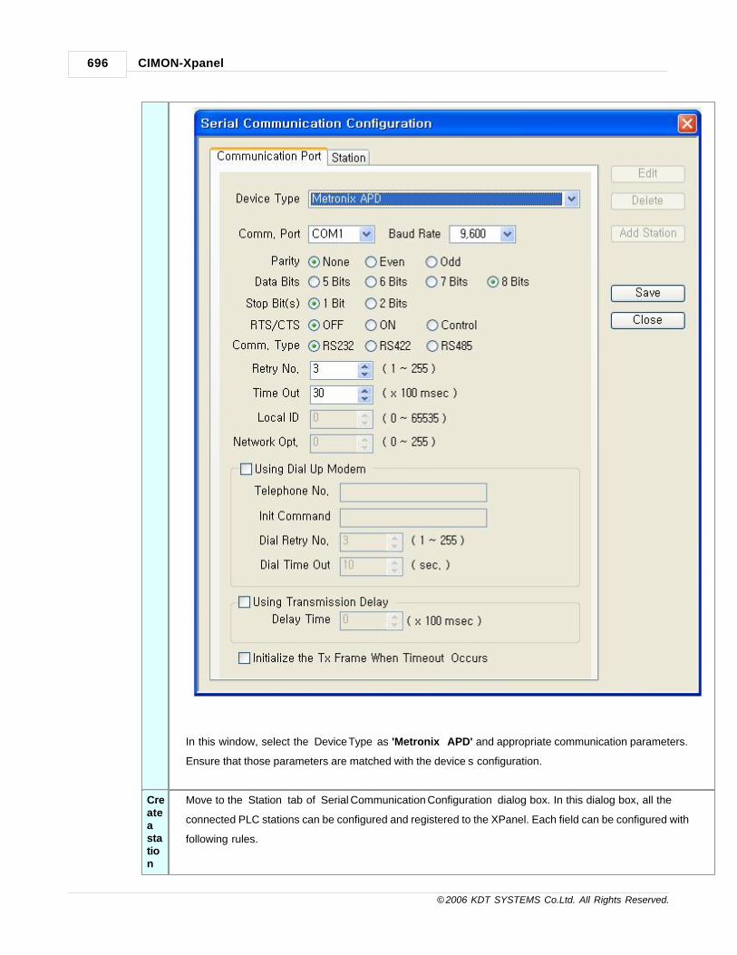
CIMON-Xpanel696
© 2006 KDT SYSTEMS Co.Ltd. All Rights Reserved.
In this window, select the ‘Device Type’ as 'Metronix APD' and appropriate communication parameters.
Ensure that those parameters are matched with the device’s configuration.
Createastation
Move to the ‘Station’ tab of ‘Serial Communication Configuration’ dialog box. In this dialog box, all the
connected PLC stations can be configured and registered to the XPanel. Each field can be configured with
following rules.

Communication Driver 697
© 2006 KDT SYSTEMS Co.Ltd. All Rights Reserved.
Station NameGive a name to the Device. This name will be used in the database window
accompanied with the ‘Device Name’.
Station Type Choose the ‘APD-VS Series’. (Another type can’t be selected.)
Network ID This field has no meaning in this driver. (Ignored in runtime)
Station No. This number must be matched with the one of Device.
16Bit Data Swap This field has no meaning in this driver.

CIMON-Xpanel698
© 2006 KDT SYSTEMS Co.Ltd. All Rights Reserved.
32Bit Data Swap This field has no meaning in this driver.
CheckSum This field has no meaning in this driver.
Comm. Error
Message Pop Up
If this item is checked, XPanel displays a communication error notification message at
every Rx and Tx error.
Otherwise(unchecked), XPanel does not display the message at data receive error.
Only when there is data transmit (writing a TAG value to the station) error, the
notification message is popped up. This message box will be closed automatically
about 5 seconds after.
Address Notation
Device DescriptionWord
Bit AccessUINT32 INT32
%MD Menu Data %MD000 ~ %MD999%MD000.0~%MD000.31
~%MD999.0~%MD999.31
R/W
AI Servo State AI000 ~ AI012AI000.0~AI000.31
~AI012.0~AI012.31
R
DOOperation
- DO000~DO011 R/W
AO AO000 ~ AO012 - R/W
Menu data address configuration
[Ex] Current Sate Pd-001 -> %MD000
Current Speed Pd-002 -> %MD001
Command Speed Pd- -> %MD002
Servo State Check address configuration
Address Description
AI0 Current Speed
AI1 Command Speed
AI2 Current Pulse
AI3 Command Pulse
AI4 Current Load
AI5 Peak Load

Communication Driver 699
© 2006 KDT SYSTEMS Co.Ltd. All Rights Reserved.
AI6 I/O State
AI7 DC Volt
AI8 Speed Refer
AI9 Speed Feedback
AI10 Torque Refer
AI11 Torque Feedback
AI12 Servo State
Servo State Set address configuration : Digital
Address Description
DO0 Alarm Reset
DO1 Alarm History Clear
DO2 Menu Initialize
DO3 Current offset store
DO4 I/O State initialization
Speed Driving
Address Description Tag Type
DO5 Direction Digital
DO6 Write : Speed, Acc & Dec time, Time Digital
AO000 Speed Analog
AO001 Current offset store Analog
AO002 I/O State initialization Analog
AO003 Time Analog
Note 1.
Direction : Configure rotation direction of motor. (0 : CCW, 1: CW)
Speed : Configure driving speed. (unit : 9999.9 r/min)
Acceleration time : Configure reaching time to regular speed by acceleration. (unit : 99.99)
Deceleration time : Configure reaching time to regular speed by deceleration. (unit : 99.99)
Time : Configure driving time from start to stop. (unit : 9999)
Note 2.
n After you configure Direction, Speed, Acc, Dec and Time, write digital value to D06 address
then Speed Driving Command will be executed.
n To show floating point data, configure data scale at database.

CIMON-Xpanel700
© 2006 KDT SYSTEMS Co.Ltd. All Rights Reserved.
Position Driving
Address Description Tag Type
DO7 Write : Position, Speed, Acc & Dec Time Digital
AO004 Position Digital
AO005 Speed Analog
AO006 Acceleration Analog
Ao007 Time Analog
Note 1.
Direction : Configure rotation direction of motor. (0 : CCW, 1: CW)
Speed : Configure driving speed. (unit : 9999.9 r/min)
Acceleration time : Configure reaching time to regular speed by acceleration. (unit : 99.99)
Deceleration time : Configure reaching time to regular speed by deceleration. (unit : 99.99)
Note 2.
n After you configure Direction, Speed, Acc, Dec and Time, write digital value to D06 address
then Speed Driving Command will be executed.

Communication Driver 701
© 2006 KDT SYSTEMS Co.Ltd. All Rights Reserved.
n To show floating point data, configure data scale at database.
Gain tuning
Address Description Tag Type
DO011 Write : Speed, Distance, Tuning range Digital
AO010 Speed Analog
AO011 Distance Analog
AO012 Tuning range Analog
n After you configure Speed, Distance and Tuning range write digital value to D06 address
then Position Driving Command will be executed.
Command Address Description Remark
Menu Data %MD000~%MD999 Menu Data R / W
State Setting
DO0 Alarm Reset
W
DO1 Alarm History Clear
DO2 Menu Initialize
DO3 Current offset Save
DO4 I/O State Initialize
Servo StateCheck
AI0 Current Speed
R
AI1 Command Speed
AI2 Current Pulse
AI3 Command Pulse
AI4 Current Load
AI5 Peak Load
AI6 I/O State
AI7 DC Voltage
AI8 Speed Refer
AI9 Speed Feedback
AI10 Torque Refer
AI11 Torque Feedback
AI12 Servo State
Speed
DO5 Direction
W
DO6 Write:Speed,Acc,Dec,Time
AO000 Speed
AO001 Acceleration Time
AO002 Deceleration Time

CIMON-Xpanel702
© 2006 KDT SYSTEMS Co.Ltd. All Rights Reserved.
AO003 Driving Time
Position
DO7 Write:Pos,Speed,Acc,Dec
W
AO004 Position
AO005 Speed
AO006 Acceleration Time
AO007 Deceleration Time
Auto Driving DO8 Auto Driving W
Stop AO008 After stop, program information reset W
EmergencyStop
DO9 Emergency Stop W
Time AO009When driving start after stop, it makes
continuous drivingW
StartingPoint
DrivingDO10
Starting Point Driving by configured modeat parameter.
W
Gain Tuning
DO11 Write : Speed, Distance, Tuning range
WAO010 Speed
AO011 Distance
AO012 Tuning range
Communication Cable Wiring
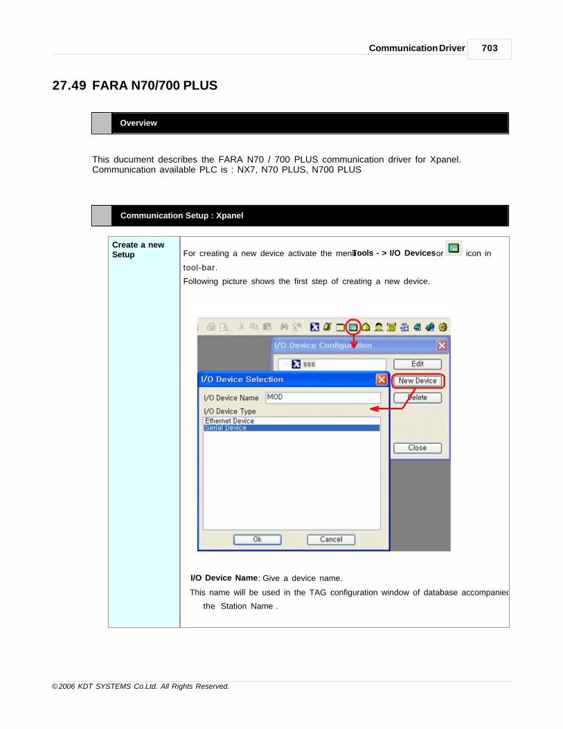
Communication Driver 703
© 2006 KDT SYSTEMS Co.Ltd. All Rights Reserved.
27.49 FARA N70/700 PLUS
Overview
This ducument describes the FARA N70 / 700 PLUS communication driver for Xpanel.Communication available PLC is : NX7, N70 PLUS, N700 PLUS
Communication Setup : Xpanel
Create a newSetup For creating a new device activate the menu ‘Tools’- >’I/O Devices’ or icon in
tool-bar.
Following picture shows the first step of creating a new device.
I/O Device Name : Give a device name.
This name will be used in the TAG configuration window of database accompanied by
the ‘Station Name’.

CIMON-Xpanel704
© 2006 KDT SYSTEMS Co.Ltd. All Rights Reserved.
Select anetwork type
I/O Device Name : ‘FARA N70/700 PLUS’
After selecting the ‘OK’ button of previous step, ‘Serial Communication
Configuration’ dialog box will be popped up as shown in following picture.
In this window, select the ‘Device Type’ as ‘FARA N70/700 PLUS’ and configure the
proper serial communication parameters. Ensure that those parameters are matched
with the device's configuration.
Create a station Move to the ‘Station’ tab of ‘Serial Communication Configuration’ dialog box. In this
dialog box, all the connected
PLC stations can be configured and registered to the XPanel. Each field can be
configured with following rules.

Communication Driver 705
© 2006 KDT SYSTEMS Co.Ltd. All Rights Reserved.
Station Name Give a name to the PLC. This name will be used in the database window accompaniedwith the ‘Device Name’.
Station Type Choose the type of connected PLC among the 'FARA N70/N700 PULS."
Network ID This field has no effect.
Station No. Specify a decimal number between 1 and 190.
16Bit Data Swap This field has no meaning in this driver.
32Bit Data Swap This field has no meaning in this driver.
Using
Checksum
This field has no effect. This driver is always checking theBCC.
Comm. Error
Message Pop
Up
If this item is checked, XPanel displays a communication error
notification message
at every Rx and Tx error.

CIMON-Xpanel706
© 2006 KDT SYSTEMS Co.Ltd. All Rights Reserved.
Otherwise(unchecked), XPanel does not display the message
at data receive error.
Only when there is data transmit (writing a TAG value to the
station) error, the
notification message is popped up. This message box will be
closed automatically
about 5 seconds after.
Address & Function Codes
Following table shows the list of valid address range used FARA PLC for each address area. The
symbol character has to be placed in the first positon of address string. The address number follows
the symbol character.
Area Symbol Analog TAG Digital TAG Remark
Ext. Input/Output R R000 - R127 R000.0 - R127.15
LINK L L000 - L063 L000.0 - L063.15
Internal Relay M M000 - M127 M000.0 - M127.15
KEEP Relay K K000 - K127 K000.0 - K127.15
Special internalOutput
F F000 - F015 F000.0 - F015.15
Word RegisterTimer/Counter
W W000 - W3071
Switch Configuration
PIN No Switch Content Dip Switch 1
1OFF Run by stored internal RAM
ON Run by stored at FLASH ROM
2OFF RS-232C Communication(IBM-PC)
ON RS-485 Communication(For Programmer)
3 4
OFF OFF 9600 bps Board rate
ON OFF 38400 bps Board rate
OFF ON 19200 bps Board rate
ON ON 4800 bps Board rate

Communication Driver 707
© 2006 KDT SYSTEMS Co.Ltd. All Rights Reserved.
Communication Cable Wiring
[XPANEL COM1 / COM2 RS232C]
27.50 Samsung BRAIN SPC Series
Overview
This document describes the Samsung BRAIN SPC Series communication driver for Xpanel.
Communication Setup : Xpanel
Create a newdevice For creating a new device activate the menu ‘Tools’- >’I/O Devices’ or icon in
tool-bar.
Following picture shows the first step of creating a new device.

CIMON-Xpanel708
© 2006 KDT SYSTEMS Co.Ltd. All Rights Reserved.
I/O Device Name : Give a device name.
This name will be used in the TAG configuration window of database accompanied by
the ‘Station Name’.

Communication Driver 709
© 2006 KDT SYSTEMS Co.Ltd. All Rights Reserved.
Select anetwork type
I/O Device Name : ‘SAMSUNG BRAIN Series’
After selecting the ‘OK’ button of previous step, ‘Serial Communication
Configuration’ dialog box will be popped up as shown in following picture.
In this window, select the ‘Device Type’ SAMSUNG BRAIN Series’ and configure the
proper serial communication parameters. Ensure that those parameters are matched
with the device's configuration.
Create a station Move to the ‘Station’ tab of ‘Serial Communication Configuration’ dialog box. In this
dialog box, all the connected
PLC stations can be configured and registered to the XPanel. Each field can be
configured with following rules.

CIMON-Xpanel710
© 2006 KDT SYSTEMS Co.Ltd. All Rights Reserved.
Station Name Give a name to the PLC. This name will be used in the database window accompaniedwith the ‘Device Name’.
Station Type Choose the type of connected PLC among the 'SPC Series."
Network ID This field has no effect.
Station No. Specify a decimal number between 1 and 190.
16Bit Data Swap This field has no meaning in this driver.
32Bit Data Swap This field has no meaning in this driver.
Using
Checksum
This field has no effect. This driver is always checking theBCC.
Comm. Error
Message Pop
Up
If this item is checked, XPanel displays a communication error
notification message
at every Rx and Tx error.
Otherwise(unchecked), XPanel does not display the message

Communication Driver 711
© 2006 KDT SYSTEMS Co.Ltd. All Rights Reserved.
at data receive error.
Only when there is data transmit (writing a TAG value to the
station) error, the
notification message is popped up. This message box will be
closed automatically
about 5 seconds after.
Address & Function Codes
Following table shows the list of valid address range used FARA PLC for each address area. The
symbol character has to be placed in the first position of address string. The address number follows
the symbol character.
Area Symbol Analog TAG Digital TAG Remark
Ext. Input / Output R R000 - R127 R000.0 - R127.15
LINK L L000 - L063 L000.0 - L063.15
Internal Relay M M000 - M127 M000.0 - M127.15
KEEP Relay K K000 - K127 K000.0 - K127.15
Special internal
OutputF F000 - F015 F000.0 - F015.15
Word Register
Timer / CounterW W000 - W3071
Communication Cable Wiring
[XPANEL COM1 / COM2 RS232C]

CIMON-Xpanel712
© 2006 KDT SYSTEMS Co.Ltd. All Rights Reserved.

Top Level IntroThis page is printed before anew top-level chapter starts
Part
XXVIII

CIMON-Xpanel714
© 2006 KDT SYSTEMS Co.Ltd. All Rights Reserved.
28 FAQ
Is there any question about CIMON - Xpanel ? See our FAQs.
See :
· Xpanel Page Update and Speed
· Xpanel IP Setting
· How to use Xpanel Printer
· How can I connect Xpanel and XpanelDesigner via USB port under Windows Vista?
· How can I display the engineering value from the raw value in my device?
· How can I export/import the Xpanel's TAG DB to/from Microsoft Excel or other 3rd vender program?
· Corrective Actions when font file delete is failed during download
· When Ethernet Loader is not operated
28.1 Xpanel Page Update and Speed
IN THIS TOPIC :
To quickly update a page(Fixed Background)
To quickly update a page(Draw Changed Object Only)
Reduce Page Size(Using 256 Bitmap)
To quickly update a page (Fixed Background)
If it arranges a lot of objects on the page in the work, update would be slower.
Considering the specificity, "Fixed Background" function makes the speed of update higher.
The "Fixed Background" function is registered to each page, and the page setting up the function of the
"Fixed Background" is handled as
the 'Object appointed with change’ and the 'Object not appointed with change’ are divided.
‘Object appointed with change’ is as follows.
· Object for which Visible, Blink, V-Size, H-Size, V-Move, H-Move, Color and Rotate are specified.
· When the change is specified for Group Object, All Object are handled as ‘Group object appointed
with change’
· Touch and Entry Data are not handled by the change.
· Tag Value, Date Time, String Value, Multi String, Trend Graph, Data Log and Alarm Summary are
handled as ‘Object appointed with change’.

FAQ 715
© 2006 KDT SYSTEMS Co.Ltd. All Rights Reserved.
"Fi
xe
d
Ba
ck
gro
un
d"
Fu
nct
ion
Set
up
Select - Page for setting "Fixed Background" function in XpanelDesigner
Click - [Tools] -> [Page Setup]
Select - "Fixed Background" of Page Properties and click - [Ok] button

CIMON-Xpanel716
© 2006 KDT SYSTEMS Co.Ltd. All Rights Reserved.
The upper page arranges the 'Tag Value Object' on Group object with the shape of a toothed wheel.
In case of the object not to set the "Fixed Background", it has picture renewal cycle for about 0.5sec
because all objects are drawn again when data updates. However, in case to set the "Fixed Background",
the picture renewal cycle is shorten because only the 'Tag Value Object' is drawn without drawing all
Objects with the shape of a toothed wheel.
To quickly update a page (Draw Changed Object Only)
Reduce the number of Objects to Quickly update a Page. Generally, if ‘Object appointed with change’ are
piled up by using ‘Draw Changed Object Only’,
the last changed Object is displayed normally.
The number difference between the general case and the case of using ‘Draw Changed Object Only’

FAQ 717
© 2006 KDT SYSTEMS Co.Ltd. All Rights Reserved.
For example, if three objects designated with change like upper page are changed at the same time, all
objects inside the yellow circle are drawn again.
In this case, 12 Object will be drawn. However, if ‘Draw Changed Object Only’ is used, three objects will be
drawn again and the drawn time will be shorten to 1/4 time.
Caution when
using
'Draw
Changed
Object Only'
Avoid the piled-up the objects designated with change when using ‘Draw Changed
Object Only’

CIMON-Xpanel718
© 2006 KDT SYSTEMS Co.Ltd. All Rights Reserved.
For instance, there are three quadrilaterals designated with color change.
In case not to use ‘Draw Changed Object Only’, the color of three quadrilaterals
are changed each other.
However, in case to use ‘Draw Changed Object Only’, the lastly changed object
is on the top of them.
'Draw
Changed
Object Only'
Setup
Select - Page for setting "Draw Changed Object Only" function in XpanelDesigner
Click - [Tools] -> [Page Setup]
Select - "Draw Changed Object Only" of Page Properties and click - [Ok] button
When using ‘Draw Changed Object Only’, Caution is as follows.
· When there are Objects designated with V-Move, H-Move and Rotate, "Draw
Changed Object Only" function doesn't operate.
· If objects that its Visible is decided by same tag are overlap, the under object is
always removed or covered due to the upper object.
· In case to use 'Fixed Background', it is filled with the background picture of the
area first value. If not, page background color would be filled.
Reduce Page Size (Using 256 Bitmap)
If the size of page file is big, there will be lots of errors at download and it will take much time to read the
page file.
Generally the page composed with basic objects doesn’t take big size. However, if the page is using many

FAQ 719
© 2006 KDT SYSTEMS Co.Ltd. All Rights Reserved.
images, the size of the page file will be bigger.
In the case of it, if you check the "Using 256 bitmap" in the Page Properties, it would change 24 bit image
of page to the 8 bit image at download and also
it would contract the size about 1/2~1/3.
Instead of it, pixel data is changed, so the shapes of editing and Xpanel could be different slightly.
"Using 256
Bitmap"
Function Setup
Select - Page for setting "Using 256 Bitmap" function in XpanelDesigner
Click - [Tools] -> [Page Setup]
Select - "Using 256 Bitmap" of Page Properties and click - [Ok] button
28.2 Xpanel IP Setting
IN THIS TOPIC :
When the project that Ethernet I/O Device is registered is operating
Using Network Setting Window of Windows CE
Using Ethernet Loader
When the project that the Ethernet I/O Device is registered in Xpanel is operating
When the project that the Ethernet I/O Device is registered in Xpanel is operating, refer to the following
pictures.
"Xpanel Config" can be displayed by pressing three corners of touch area as follows.

CIMON-Xpanel720
© 2006 KDT SYSTEMS Co.Ltd. All Rights Reserved.
Push the " SW Keyboard " button. For removing the ‘SW Keyboard’ from screen, push the ‘SW
Keyboard’ button again.
Push the " Comm. Config " button. -> Select - [Ethernet] in the I/O Device selection box

FAQ 721
© 2006 KDT SYSTEMS Co.Ltd. All Rights Reserved.
IP Setting Window is displayed.
Change the IP Setting using 'SW Keyboard' and click the [OK] button of Communication Setup
window.
Click the [OK] button
Click the [OK] button to close the system
Using Network Setting Window of Windows CE
Close - Xpanel Program
When it is connected with ActiveSync, close - Xpanel Program by "Online -> Xpanel Program Stop”
When it is not connected with ActiveSync, close - Xpanel Program by [Exit] button of “Xpanel Config”
window
Xpanel wallpaper is displayed.

CIMON-Xpanel722
© 2006 KDT SYSTEMS Co.Ltd. All Rights Reserved.
Touch the screen under to appear Taskbar . Execute the software keyboard by touching the icon at
the right corner of the task bar.

FAQ 723
© 2006 KDT SYSTEMS Co.Ltd. All Rights Reserved.
Change the content of Settings window using software keyboard, and Click the [OK] button.
Close - [LAN91C111 Ethernet Driver] Settings window by button.
Close - [Network and Dial-up Connections] window by button.
Close the system by selecting 'Start -> Suspend' for storing the network settings permanently.
Using Ethernet Loader
* Ethernet Loader supports OS version 2.00 or late.
If the project is running, click the [Exit] button in the “Xpanel config” window.
Change - "IP" by using IP Input Keyboard

CIMON-Xpanel724
© 2006 KDT SYSTEMS Co.Ltd. All Rights Reserved.
* If "DHCP" is not checked, IP Address, Subnet Mask, and Gateway can be changed.
For application the changed configurations, select the [Apply this new setting] button.
Click the [OK] button then it will go on.
28.3 How to use Xpanel Printer
This manual explains "Printer Setup" and "Print Out Setup".
Xpanel can connect USB Printer that is support PCL. (USB Host support model)
IN THIS TOPIC :
Xpanel Printer Setup Print Out Setup
Xpanel Printer Setup
"Xpanel Config" can be displayed by pressing three corners of touch area as follows.

FAQ 725
© 2006 KDT SYSTEMS Co.Ltd. All Rights Reserved.
Push the " SW Keyboard " button. For removing the ‘SW Keyboard’ from screen, push the ‘SW
Keyboard’ button again.
Push the " Printer " button.

CIMON-Xpanel726
© 2006 KDT SYSTEMS Co.Ltd. All Rights Reserved.
Printer Select the printer type. Xpanel supports ‘PCL Inkjet’ and ‘PCL Laser’ printer
supporting PCL.
Port Select a port that the printer is connected.
· USB Printer : If a printer is connected to the Xpanel via the USB host port,
select the "LPT1:" The LPT1 port is automatically detected and displayed
when the printer is connected.
· Network Printer : If a printer is connected with the network,
select the "Network ". In this case, the ‘Net Path’ field must be configured as
following example.
Format : \ \PC_name\Printer_name
Example : \ \ k i m 4 0 \ c a n o n i r 2
Paper Size Select - Paper size of printer.
Draft Mode If this mode is not selected, the size of the output image decreases though the
image is clearly output
Color If you select “PCL Inkjet”, enable Print out with Color.
Print Range Select - All
Orientation Select - Print orientation
Margins Adjust - Print margins.
If setting is finished, push - [OK] button.
If the ‘Port’ is chosen as ‘Network’, the Xpanel tries to connect the PC through network and pops-up
following logon dialog box.

FAQ 727
© 2006 KDT SYSTEMS Co.Ltd. All Rights Reserved.
Enter the user name and password to the logon dialog box above, and then push the button.
Following dialog box is displayed to Xpanel.
If [Yes] is chosen, the password entered will be stored in disk permanently.
Otherwise (in case of [No]), the Xpanel will ask the password whenever try to use the network printer.
Touch - [System Shutdown] of "Xpanel Config" window to save the setup data
(If the ‘System Shutdown’ was not executed, the setup data will be canceled and the previous one will
be restored when the system is restarted.)
To continue, push [OK] button. Xpanel will be shutdown.
Print Out Setup
Xpanel provides the ‘HardCopy()’ function for printing the screen image.

CIMON-Xpanel728
© 2006 KDT SYSTEMS Co.Ltd. All Rights Reserved.
MakeaPrintButton
1. Select - Object to use print button from screen
a. Select - [Touch] in 'Object Config' and [Command Expression] in 'Action'
b. Input - HardCopy(); in Command. Click - [ O K ]
HardCopy() function outputs a present screen to the selected printer.
2. Download the project to Xpanel
3. Push "Print Screen " area.

FAQ 729
© 2006 KDT SYSTEMS Co.Ltd. All Rights Reserved.
4. After a while, print completion message box is displayed.
28.4 How can I connect Xpanel and XpanelDesigner via USB portunder Windows Vista?
V1.19 or later version of Xpanel operating system supports Microsoft Windows Vista.
The most recent Xpanel operating system image is provided with XpanelDesigner.
If your current XpanelDesigner does not include V1.19 or later version of OS image, you need to upgrade
your XpanelDesigner first.
Please check the web-page (http://kdtsys.com/kor) for the new version of XpanelDesigner.
And "Windows Mobile Device Center" is needed for PC instead of "ActiveSync" which is used under previous
Windows version.
"Mobile Device Center" is abailable at http://www.microsoft.com/.

CIMON-Xpanel730
© 2006 KDT SYSTEMS Co.Ltd. All Rights Reserved.
28.5 How can I display the engineering value from the raw value in mydevice?
Xpanel provides two different method to calculate a scaled engineering data.
System designer can choose one of there two methods with the "Scale" option in TAG database.
If this option is checked, Xpanel performs 'Scale/Offset' method.
IN THIS TOPIC :
Scale / Offset Method Proportional Method
Scale / Offset Method
The 'Scale/Offset' method uses following formula for calculating the engineering value.
Veng = Vraw X Scale + Offset
Vraw Read data from device. Not processed, raw value from device.
Veng Engineering data. (The data which will be displayed in Xpanel's screen)
(Example 1) If an analog TAG was configured as following picture, and the Vraw from device is
32768,

FAQ 731
© 2006 KDT SYSTEMS Co.Ltd. All Rights Reserved.
Veng = (32768 X 0.1) - 3276.8 = 3276.8 -3276.8 = 0
As shown in above example, the engineering data configurations (Min Value and Max Value) do not
affect the raw value processing.
But, in case of proportional method (if the 'Scale' option was not checked), the engineering data Min/
Max value configurations are important factors.
See the next following page.
Proportional Method
The 'Proportional Method' process the law value twice by using following formulas.
Scale = (Veng_max - Veng_min) / (Vraw_max - Vraw_min)
Offset = Vraw_min - Vraw_min
Veng = Vraw X Scale + Offset
Vraw Read data from device. Not processed, raw value from device.
Veng Engineering data. (The data which will be displayed in Xpanel's screen)
Vraw_max , Vraw_min Raw data rage configurations
Veng_max , Veng_min Engineering data range configurations
First, it calculates the scale and offset values from min/max configurations.
The calculated scale and offset values are applied to the same formula as 'Scale/Offset Method' for
acquiring the final engineering value.
(Example 2) If an analog TAG was configured as following picture, and the Vraw from device is
32768,

CIMON-Xpanel732
© 2006 KDT SYSTEMS Co.Ltd. All Rights Reserved.
Scale = (3276.7 - (-3276.8)) / (65535 - 0) = 0.1
Offset = (-3276.8) - 0 = -3276.8
Veng = (32768 X 0.1) - 3276.8 = 3276.8 -3276.8 = 0
Note that above two examples gave the same result.
28.6 How can I export/import the Xpanel's TAG DB to/from MicrosoftExcel or other 3rd vender program?
The XpanelDesigner does not have a special menu for TAG DB exporting and importing.
However, the clipboard function of Windows can be used for the same purpose.
Use the "Copy" function of "Edit" menu while the TAG DB window is opened and some of TAGs in
DB are under selected state.
And next, activate the Microsoft Excel, and use "Paste" function of "Edit" menu. Following table can
be helpful to edit each TAG data in Excel worksheed.
CellTAG Type
RemarkGroup Digital Analog String
A TAG name (including the group name)
B 0 1 2 3 TAG type code
C TAG Description
D Real/Virtual TAG Flag0 = Virtual TAG
1 = Real TAG
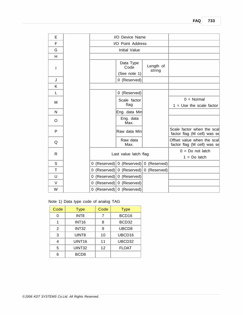
FAQ 733
© 2006 KDT SYSTEMS Co.Ltd. All Rights Reserved.
E I/O Device Name
F I/O Point Address
G Initial Value
H
I
Data TypeCode
(See note 1)
Length ofstring
J 0 (Reserved)
K
L 0 (Reserved)
MScale factor
flag
0 = Normal
1 = Use the scale factor
N Eng. data Min.
OEng. data
Max.
P Raw data Min.Scale factor when the scalefactor flag (M cell) was set
QRaw data
Max.Offset value when the scalefactor flag (M cell) was set
R Last value latch flag0 = Do not latch
1 = Do latch
S 0 (Reserved) 0 (Reserved) 0 (Reserved)
T 0 (Reserved) 0 (Reserved) 0 (Reserved)
U 0 (Reserved) 0 (Reserved)
V 0 (Reserved) 0 (Reserved)
W 0 (Reserved) 0 (Reserved)
Note 1) Data type code of analog TAG
Code Type Code Type
0 INT8 7 BCD16
1 INT16 8 BCD32
2 INT32 9 UBCD8
3 UINT8 10 UBCD16
4 UINT16 11 UBCD32
5 UINT32 12 FLOAT
6 BCD8

CIMON-Xpanel734
© 2006 KDT SYSTEMS Co.Ltd. All Rights Reserved.
28.7 Corrective Actions when font file delete is failed during download
It is possible if error font file is downloaded to Xpanel.
Corrective Action 1
1. Click - [Online] -> [Setup Link]. Select the link type of Xpanel.
2. Click - [Online] -> [Download to Xpanel(PC->Xpanel)]
3. Uncheck - [Download The Font File] of "Download to Xpanel(PC->Xpanel)"
4. Click - [Ok]
Corrective Action 2
1. Close - Xpanel Program by [Exit] button of “Xpanel Config” window

FAQ 735
© 2006 KDT SYSTEMS Co.Ltd. All Rights Reserved.
2. Two touch the [My Device] of this screen.
3. Two touch the [Xpanel]

CIMON-Xpanel736
© 2006 KDT SYSTEMS Co.Ltd. All Rights Reserved.
4. Select the [Bin] folder. Delete the folder by touching [File] -> [Delete].
5. Select - [Ok] in the error window while deleting it.
6. When it is completed, reset the Xpanel.
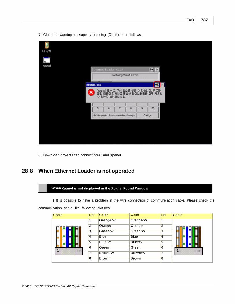
FAQ 737
© 2006 KDT SYSTEMS Co.Ltd. All Rights Reserved.
7. Close the warning massage by pressing [OK] button as follows.
8. Download project after connecting PC and Xpanel.
28.8 When Ethernet Loader is not operated
When Xpanel is not displayed in the Xpanel Found Window
1. It is possible to have a problem in the wire connection of communication cable. Please check the
communication cable like following pictures.
Cable No Color Color No Cable
1 Orange/W Orange/W 1
2 Orange Orange 2
3 Green/W Green/W 3
4 Blue Blue 4
5 Blue/W Blue/W 5
6 Green Green 6
7 Brown/W Brown/W 7
8 Brown Brown 8

CIMON-Xpanel738
© 2006 KDT SYSTEMS Co.Ltd. All Rights Reserved.
<Direct Cable: Host <-> HUB : When Xpanel is connected with PC via the hub>
Cable No Color Color No Cable
1 Orange/W Green/W 1
2 Orange Green 2
3 Green/W Orange/W 3
4 Blue Blue 4
5 Blue/W Blue/W 5
6 Green Orange 6
7 Brown/W Brown/W 7
8 Brown Brown 8
<Crossover Cable: Host <-> Host : When Xpanel is connected with PC via the cable>
2. In case of the connection with another PC of network, Xpanel doesn’t send its own IP information any
more.
After the end of Xpanel of another PC for 15~20 seconds, rebut Xpanel Designer and check its
condition of the connection.
3. In the condition of 1:1 connection with Xpanel, check the “Obtain an IP address automatically” in the IP
settings.
If it is set, its IP is assigned from DHCP server. if not, normal IP to PC would not be assigned and
Ethernet communication can’t work.
The network setting of PC can be confirmed by the under method.
Click - [Control Panel] -> [Network Connections]

FAQ 739
© 2006 KDT SYSTEMS Co.Ltd. All Rights Reserved.
Select - [Local Area Connection] -> [Properties] by using the right button of mouse.

CIMON-Xpanel740
© 2006 KDT SYSTEMS Co.Ltd. All Rights Reserved.
Click - [Internet Protocol(TCP/IP)] -> [Properties]
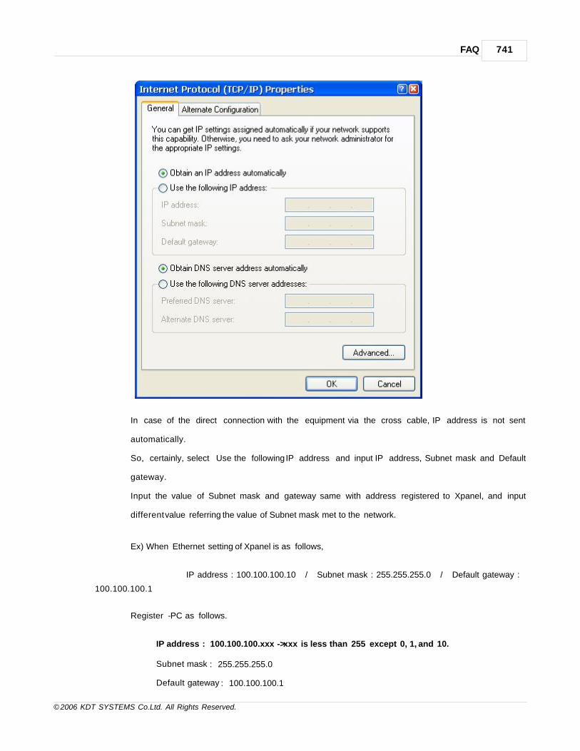
FAQ 741
© 2006 KDT SYSTEMS Co.Ltd. All Rights Reserved.
In case of the direct connection with the equipment via the cross cable, IP address is not sent
automatically.
So, certainly, select “Use the following IP address” and input IP address, Subnet mask and Default
gateway.
Input the value of Subnet mask and gateway same with address registered to Xpanel, and input
different value referring the value of Subnet mask met to the network.
Ex) When Ethernet setting of Xpanel is as follows,
IP address : 100.100.100.10 / Subnet mask : 255.255.255.0 / Default gateway :
100.100.100.1
Register - PC as follows.
IP address : 100.100.100.xxx -> xxx is less than 255 except 0, 1, and 10.
Subnet mask : 255.255.255.0
Default gateway : 100.100.100.1

CIMON-Xpanel742
© 2006 KDT SYSTEMS Co.Ltd. All Rights Reserved.
4. If Ethernet Loader program of Xpanel is closed, It will be not displayed in the item.
Do not close Ethernet Loader window when Xpanel is running.
If you close unfortunately, it can be restarted automatically by On/Off the power of Xpanel.
5. The Xpanel information frame can be intercepted by the firewall program set up in PC.
After closing a real time monitoring function and firewall program, restart Xpanel Designer and check its
action.
6. Ethernet Loader is supported in the Xpanel OS v2.00 or late.
After butting, you can check OS version at the System Log window of Xpanel Config.

FAQ 743
© 2006 KDT SYSTEMS Co.Ltd. All Rights Reserved.
When program run fail or create fail message happens continually during project download
1. The connection of the cable is normal but the network setup could not be matched.
Referring 3.clauses described at the upper picture, check IP setup between PC and Xpanel.
2. It is possible to close Ethernet Loader program of Xpanel by mistake.
Click the [Exit] button at the “Xpanel config” for closing Xpanel project and check the Ethernet Loader
program described at the 4.clauses.
Ethernet connection test of PC and Xpanel
1. The network connection with Xpanel can be confirmed by an easy operation in PC.
2. Confirm the IP of the PC via IPCONFIG.
2.1 Select - [Start] -> [Run] on the PC.
2.2 Input “cmd” in the open of 'Run' window and click the [OK] button.
2.3 Command window is displayed.

CIMON-Xpanel744
© 2006 KDT SYSTEMS Co.Ltd. All Rights Reserved.
2.4 Input “ipconfig” in the Command window and push the ‘Enter' key.
2.5 If the cable is connected, IP information setting to the PC is displayed on the monitor.
If not, "Media disconnected" message is displayed.
3. Ethernet communication connection test (Ping test)
3.1 Input "ping xxx.xxx.xxx.xxx " in Command window and push the ‘Enter' key. "xxx.xxx.xxx.xxx " is a
IP of Xpanel.
Ex) Ping 172.16.106.52
3.2 If the network is connected normally, Request time is displayed on the monitor.
If not, "Request timed out" message is displayed.
Corrective Actions when Font File delete is failed during download
1. It is possible if error font file is downloaded to Xpanel.
2. Please take measures in the following order.
2.1 Close - Xpanel Program by [Exit] button of “Xpanel Config” window

FAQ 745
© 2006 KDT SYSTEMS Co.Ltd. All Rights Reserved.
2.2 Two touch the [My Device] of this screen.
2.3 [Xpanel] folder is displayed.
2.4 Two touch the [Xpanel]

CIMON-Xpanel746
© 2006 KDT SYSTEMS Co.Ltd. All Rights Reserved.
2.5 Select the "Bin" folder and remove folder by pressing button. Select - [Ok] in the error
massages while deleting it.
2.6 When it is completed, reset the Xpanel.
2.7 There will be the background picture and the warming massage not to find program.
2.8 Close the warning massage by pressing [OK] button and download project after connecting PC
and Xpanel.

Index 747
© 2006 KDT SYSTEMS Co.Ltd. All Rights Reserved.
Index- A -Access Privilege 308
AddMessage 358
AlarmCsvWr 356
AlarmPrint 355
ALLENBRADLEY DF1 688
Analog TAG 104
Apply from alarms 370
Apply scroll message using script 370
ASIC Protocol 383
- B -Barcode Scanner 389
Blink 162
- C -CIMON SCADA 설정 300
ClearAlarmLog 358
ClosePort 346
Color 167
comm. monitor 61
comm.config 62
Command Script 319
Communication Driver 382
Conditional Expression 319
Configuration Items 369
configuration tool 60
CONTINUE 324
- D -Danfoss 394
Data Bridge 200
Data Logger 193
Data Logging Configuration 193
database 97
Database Edit using EXCEL 108
Database Window 98
DataLog 336
date/time 68
DELTA TAU 406
Developing Environment Setup 45
digital tag 104
DirectNet 464
DO-WHILE 322
- E -Edit Data Bridge Model 200
Editing recipe data using system memory 230
EntryData 171
Essential Safety Precautions 32
Ethernet loader 737
Ethernet 통신 설정 114
Example of using system memory about openedpage log. 223
exit 74
- F -FAQ 714
FAQ_CorrectiveActions 734
FC300 394
FOR Statement 323
Frame Editor 139
FrameOpen 331
FR-E500 533
Fuji 639, 680
- G -General Safety Precautions 34
GetSecurity 353
GetSysMem 361
GetTime 332
GLOFA 412, 419, 469, 477, 484, 627
GOTO 324
Graphic Page Editor 134
Group TAG 103
- H -HardCopy 345
HITACHI Inverter SJ300/L300P 428
H-Move 165

CIMON-Xpanel748
© 2006 KDT SYSTEMS Co.Ltd. All Rights Reserved.
How can I export/import the Xpanel's TAG DBto/from Microsoft Excel or other 3rd venderprogram 732
How to use Database 99
H-Size 163
- I -I/O 디바이스 설정 113
I/O디바이스 113
IF-ELSE 322
Installation / Dimensions 38
Interfaces 41
Internal Functions 326
IP설정 719
- K -KDT SYSTEM 437, 445
KDT Systems Xpanel Master 453
Keyence KV 459
keypad page 185
KOYO 464
- L -LcdBacklight 364
LcdBrightDown 363
LcdBrightUp 363
Library 143
LOG Trend 265
LogOff 352
LogOn 351
LogOnWin 352
LSIS 412, 419, 469, 484, 497, 529, 627
LS산전 477, 489
LS산전 Master-K S 시리즈 PLC Enet 521
LS산전 Master-K S 시리즈 PLC 로더 504
LS산전 Master-K S 시리즈 PLCCnet 509
LS산전Master-KH시리즈PLCCnet 515
- M -MakeCsv 334
MakeCsvUsb 335
MakeLogCsv 335
Melsec 1C 536
MELSEC 1E 551
Melsec 3E 546
Melsec 3E ASCII 557
Melsec A Series 563
Melsec FX Series 568, 573
Melsec Q Series 578
MELSEC_FX2N-1020GM 586
METRONIXAPD 694
MEWTOCOL-COM 601
misc,config 66
MITSUBISHI 533, 536, 546, 551, 557, 563,568, 573, 578
MODBUS 591, 596
ModelConfiguration 213
- N -NAIS 601
network 54
NumToStr 350
- O -Object Properties 158
OMRON 606, 612
OpenConfigWin 353
OpenPort 345
Operator 317
Overview 97
- P -Package 36
Page Properties 135
PageOpenS 331
Peripherals 53
PMAC 406
Printer 730
printer : printer setup 69
Printer 사용 방법 724
Project setup and download 91
- R -RcpConfig() 342

Index 749
© 2006 KDT SYSTEMS Co.Ltd. All Rights Reserved.
RcpCsvRd 340
RcpCsvWr 341
RcpDownload 337
RcpFileRead 339
RcpFileStore 338
RcpGetSysMem 359
RcpMemDown 339
RcpMemUp 339
RcpSetSysMem 360
RcpStop 338
RcpUpload 337
ReceiveByte 348
Recipe 212
Recipe Operator Interface 217
RemoveMessage 359
RETURN 325
RK512/3964R 648
Rotate 167
RunApp 333
RUNSCRIPT 326
- S -SAIA S-BUS 631
Scope Trend 245
ScrCapture 344
screen captrure 68
Script 313
Scroll Message Setup 369
Scroll_Message 368
Security 306
SendByte 347
SendString 347
Serial 통신설정 117
SetDate(R1,R2,R3) 365
SetSpeed(R1) 365
SetTime(R1) 365
SIEMENS 648
SIEMENS S7 Ethernet 654
SIEMENS S7 MPI 659, 665
Sleep 345
SoftKeyboard 354
SPC Trend 251
Specification 37
ST Trend 258
Statements 321
StaticBeepCtrl(R1) 364
String Construction 280
String Editor 280
String TAG 107
StringTable 332
StrToNum 349
Structure of Program 313
Style 160
sw keyboard 69
SWITCH-CASE 323
SysMemFill 363
SysMemMove 362
system log 60
System Memory 221
System Overview 53
system shutdown 73
- T -tag 97
TimeStr 333
Touch 169
touch calibrate 67
TouchCalib 357
Trend 238
TrendCsvWr 343
- U -User Library 155
User LogOff 310
User LogOn 310
User Registration 306
Using Data Logging 197
Using Multiple Language 287
Using System Memory Tag 221
- V -Visible 161
Vista 729
V-Move 164
V-Size 162
- W -WHILE 322

CIMON-Xpanel750
© 2006 KDT SYSTEMS Co.Ltd. All Rights Reserved.
Wiring 44
- X -XGT 489, 497
Xpanel 13
xpanel Designer 55, 76, 86, 87, 97
Xpanel Project download 76
Xpanel unit 56
XpanelDesigner 13
Xpanel의 데이터 정의 299
XY Trend 271
- Y -YOKOGAWA 672
YT Trend 238
- Z -경보 122
경보그룹 122
경보설정 123
경보요약 128
다국어 287
다국어 테이블 사용하여 운전중 표시문자 변경하기 292
데이터서버 299
데이터업데이트 714
마법사 오브젝트 144
설치안내 32
속도개선 714
입력기 등록 287
키 입력 설정 189
키 입력창 189
키패드 185
페이지전환 714
한 페이지에서 다국어 문자열 표시하기 290

Endnotes 2... (after index)
751
© 2006 KDT SYSTEMS Co.Ltd. All Rights Reserved.

Back Cover