xperia m working instructions 1277-1343_rev2
DESCRIPTION
Xperia M working instructionsTRANSCRIPT
1277-1343 Rev 2 Sony Mobile Communications AB – Company Internal
Working Instructions - mechanical -
C1904, C1905, C2004, C2005
XperiaTM M, XperiaTM M Dual

Working Instructions (mech)
1277-1343 Rev 2 Sony Mobile Communications AB – Company Internal 2(72)
CONTENTS
1 Exterior Views .................................... ............................................. 4
1.1 C1904, C1905, C2004, C2005 ............................................................... 4
2 Tools ............................................. ................................................... 5
3 Disassembly........................................ ............................................ 6
3.1 Battery Cover Assy ................................ .............................................. 6
3.2 Battery ........................................... ........................................................ 7
3.3 Rear Cover Assy ................................... ............................................... 7
3.4 Main PBA .......................................... .................................................. 10
3.5 ANT Board ......................................... ................................................. 12
4 Replacement ....................................... .......................................... 14
4.1 Battery Cover Assy ................................ ............................................ 14
4.2 ANT Board ......................................... ................................................. 15
4.3 Ant Speaker Gasket ................................ ........................................... 16
4.4 Camera Key ........................................ ................................................ 17
4.5 Coaxial Cable ..................................... ................................................. 19
4.6 Diffusion Film .................................... ................................................. 21
4.7 Display ........................................... ..................................................... 22
4.8 Earspeaker& EarSpeaker Adhesive ................... ............................... 26
4.9 Flash LED Gasket .................................. ............................................. 28
4.10 Front Cover Assy .................................. ............................................. 29
4.11 Kapton Tape TP connector .......................... ...................................... 30
4.12 Label ............................................. ...................................................... 31
4.13 Light Bar Gasket .................................. .............................................. 32
4.14 Light Pipe Sensor & Rubber Sensor ................. ................................ 33
4.15 Link FPC & Link FPC Gasket ........................ ..................................... 35
4.16 Link FPC Gasket B ................................. ............................................ 38
4.17 Loudspeaker & Speaker Gasket ...................... .................................. 39
4.18 Main Camera 5M&Camera Connector Mylar Tape&Camera G asket41
4.19 Microphone Rubber & Microphone Mesh ............... .......................... 43
4.20 2nd Microphone Rubber ................................. ..................................... 45
4.21 Rear Cover ........................................ .................................................. 46
4.22 Reflective Sheet .................................. ............................................... 47
4.23 RF Port Rubber .................................... ............................................... 48
4.24 SIM Board & SIM Board Adhesive .................... ................................. 49
4.25 Speaker Mesh ...................................... ............................................... 51
4.26 Speaker Mesh on Rear Cover ........................ .................................... 52
4.27 Speaker Sponge .................................... ............................................. 53
4.28 Touch Panel & Touch Panel Adhesive ................ ............................. 54

Working Instructions (mech)
1277-1343 Rev 2 Sony Mobile Communications AB – Company Internal 3(72)
4.29 Water Indicator ................................... ................................................ 61
4.30 Volume Key ........................................ ................................................ 63
4.31 Board Swap - Replacement .......................... ..................................... 65
4.32 Board Swap – Change Label ......................... .................................... 65
4.33 Board Swap – Customize of Software ................ .............................. 65
5 Reassembly......................................... .......................................... 66
5.1 Front Cover Assy& ANT Board ....................... .................................. 66
5.2 Main PBA .......................................... .................................................. 68
5.3 Rear Cover Assy ................................... ............................................. 69
5.4 Battery ........................................... ...................................................... 70
5.5 Battery Cover Assy ................................ ............................................ 70
6 Revision History .................................. ......................................... 72
For general information about mechanical repair rel ated issues, refer to 1220-1333: Generic Repair Manual - mechanical
Working Instructions (mech)
1277-1343 Rev 2 Sony Mobile Communications AB – Company Internal 4(72)
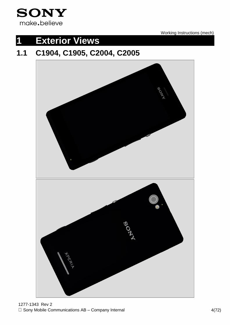
1 Exterior Views
1.1 C1904, C1905, C2004, C2005

Working Instructions (mech)
1277-1343 Rev 2 Sony Mobile Communications AB – Company Internal 5(72)
2 Tools
SPECIAL TOOLS 1. Torque Screwdriver 2. Front Opening Tool 3. Bits (T5) 4. Bits (JCIS No 0) 5. Flex Film Assembly Tool 6. Guitar Pick
For part no’s on the tools above, refer to the ‘Too ls Catalogue/Matrix’!
SPECIAL TOOLS 7. Press Tool 8. Press Fixture
STANDARD TOOLS 1. Tweezers
Working Instructions (mech)
1277-1343 Rev 2 Sony Mobile Communications AB – Company Internal 6(72)
3 Disassembly
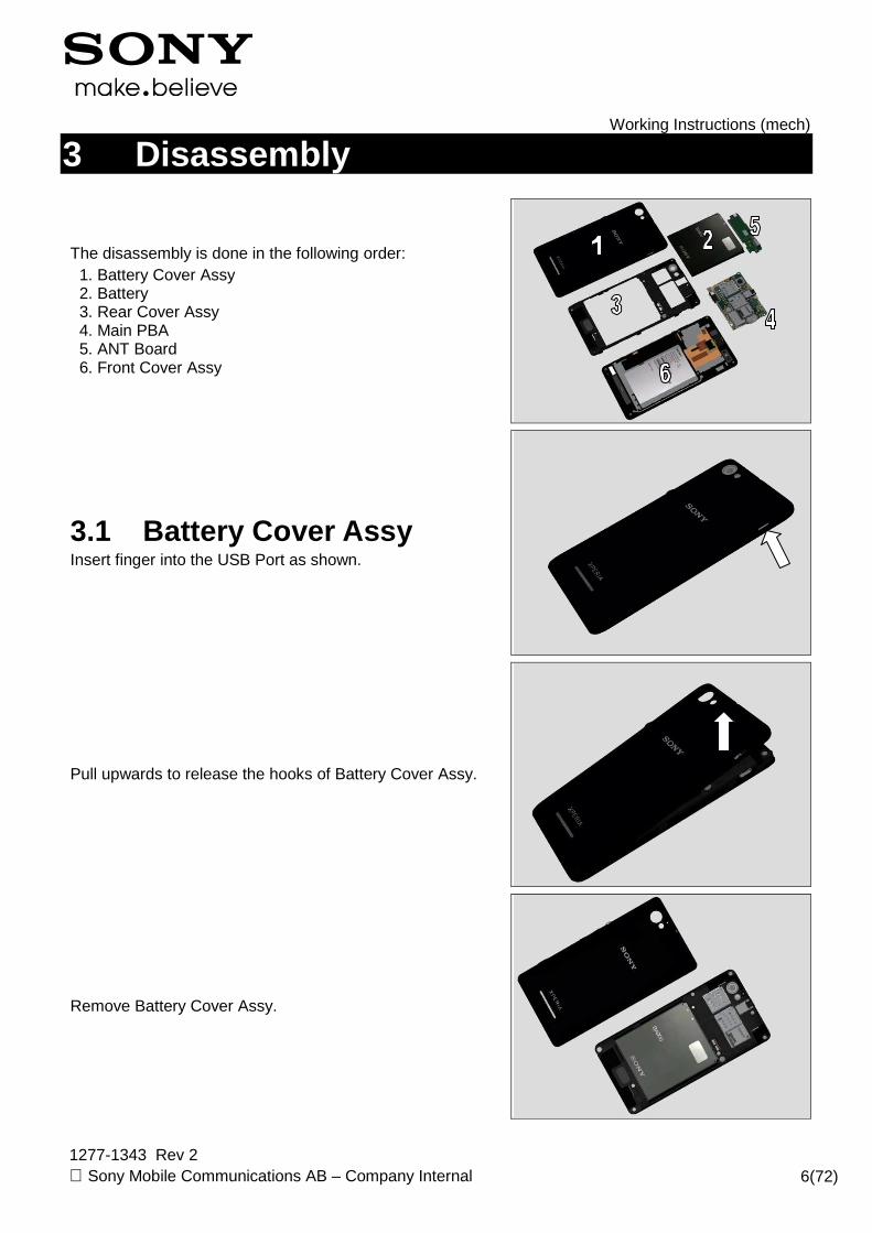
The disassembly is done in the following order: 1. Battery Cover Assy 2. Battery 3. Rear Cover Assy 4. Main PBA 5. ANT Board 6. Front Cover Assy
3.1 Battery Cover Assy Insert finger into the USB Port as shown.
Pull upwards to release the hooks of Battery Cover Assy.
Remove Battery Cover Assy.
Working Instructions (mech)
1277-1343 Rev 2 Sony Mobile Communications AB – Company Internal 7(72)
Disassembly
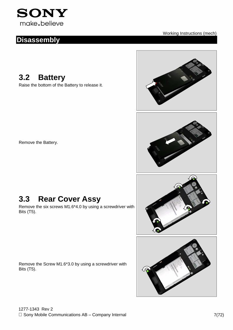
3.2 Battery Raise the bottom of the Battery to release it.
Remove the Battery.
3.3 Rear Cover Assy Remove the six screws M1.6*4.0 by using a screwdriver with Bits (T5).
Remove the Screw M1.6*3.0 by using a screwdriver with Bits (T5).

Working Instructions (mech)
1277-1343 Rev 2 Sony Mobile Communications AB – Company Internal 8(72)
Disassembly
Remove the Screw M1.4*2.4 by using a screwdriver with Bits (JCIS No 0).
There are eleven hooks secure the Rear Cover as shown.
Insert the Front Opening Tool and pull upwards to release the right bottom corner as shown
Release the two hooks on the bottom side.

Working Instructions (mech)
1277-1343 Rev 2 Sony Mobile Communications AB – Company Internal 9(72)
Disassembly
Release the left side as shown.
Release the right side as shown.
Raise the bottom side at approximately 30o.
Pull upwards to release the top side as shown.
Working Instructions (mech)
1277-1343 Rev 2 Sony Mobile Communications AB – Company Internal 10(72)
Disassembly
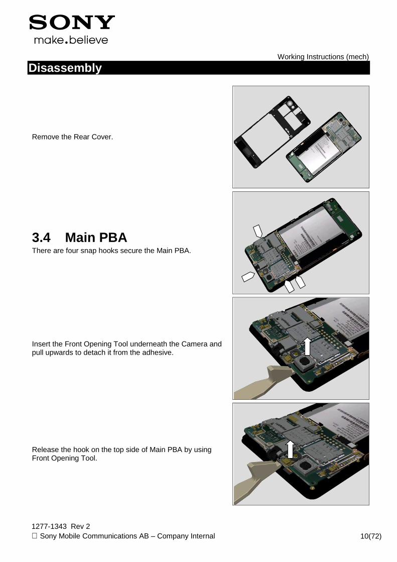
Remove the Rear Cover.
3.4 Main PBA There are four snap hooks secure the Main PBA.
Insert the Front Opening Tool underneath the Camera and pull upwards to detach it from the adhesive.
Release the hook on the top side of Main PBA by using Front Opening Tool.
Working Instructions (mech)
1277-1343 Rev 2 Sony Mobile Communications AB – Company Internal 11(72)
Disassembly
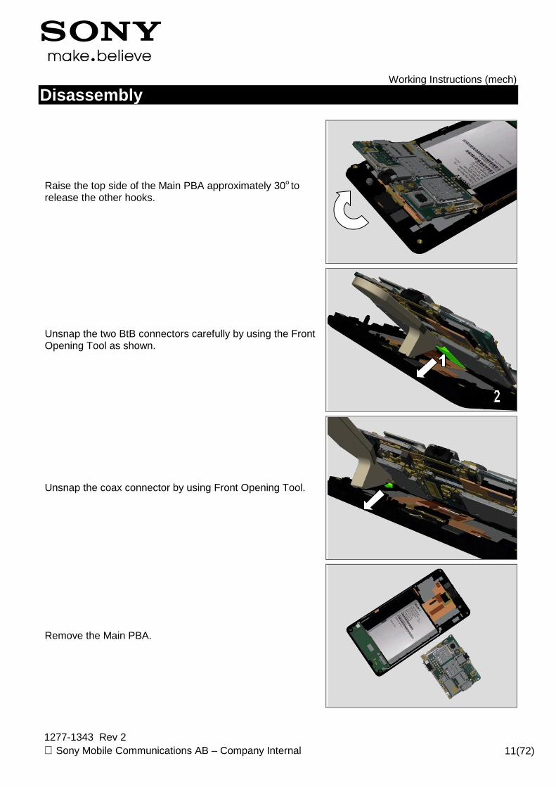
Raise the top side of the Main PBA approximately 30o to release the other hooks.
Unsnap the two BtB connectors carefully by using the Front Opening Tool as shown.
Unsnap the coax connector by using Front Opening Tool.
Remove the Main PBA.

Working Instructions (mech)
1277-1343 Rev 2 Sony Mobile Communications AB – Company Internal 12(72)
Disassembly
3.5 ANT Board There are two hooks snap the ANT Board.
Release the coax connector by using the Front Opening Tool gently.
Release the hook on the bottom side.
Raise the bottom side of the ANT Board approximately 30o.

Working Instructions (mech)
1277-1343 Rev 2 Sony Mobile Communications AB – Company Internal 13(72)
Disassembly
Unlock the ZIF connector.
Remove the ANT Board.
Working Instructions (mech)
1277-1343 Rev 2 Sony Mobile Communications AB – Company Internal 14(72)
4 Replacement
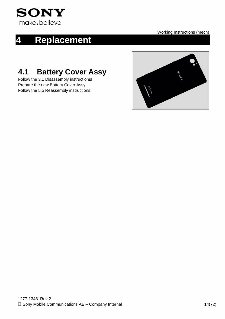
4.1 Battery Cover Assy Follow the 3.1 Disassembly instructions! Prepare the new Battery Cover Assy. Follow the 5.5 Reassembly instructions!

Working Instructions (mech)
1277-1343 Rev 2 Sony Mobile Communications AB – Company Internal 15(72)
Replacement 4.2 ANT Board
Follow the 3.1 – 3.3 Disassembly instructions! Prepare the new ANT Board. Follow the 4.3, 4.27, 4.29 Installation Instructions! Follow the 5.3 – 5.5 Reassembly instructions!
Working Instructions (mech)
1277-1343 Rev 2 Sony Mobile Communications AB – Company Internal 16(72)
Replacement
4.3 Ant Speaker Gasket
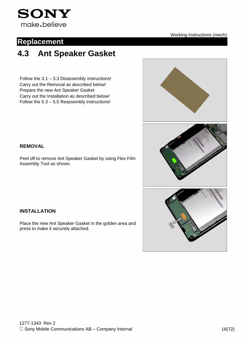
Follow the 3.1 – 3.3 Disassembly instructions! Carry out the Removal as described below! Prepare the new Ant Speaker Gasket Carry out the Installation as described below! Follow the 5.3 – 5.5 Reassembly instructions!
REMOVAL Peel off to remove Ant Speaker Gasket by using Flex Film Assembly Tool as shown.
INSTALLATION Place the new Ant Speaker Gasket in the golden area and press to make it securely attached.

Working Instructions (mech)
1277-1343 Rev 2 Sony Mobile Communications AB – Company Internal 17(72)
Replacement
4.4 Camera Key
Follow the 3.1 Disassembly instructions! Carry out the Removal as described below! Prepare the new Camera Key. Carry out the Installation as described below! Follow the 5.5 Reassembly instructions!
REMOVAL Push with the tweezers on the Camera Key from outside until the key becomes released.
Remove it.
INSTALLATION Place the Camera Key into proper place.
Working Instructions (mech)
1277-1343 Rev 2 Sony Mobile Communications AB – Company Internal 18(72)
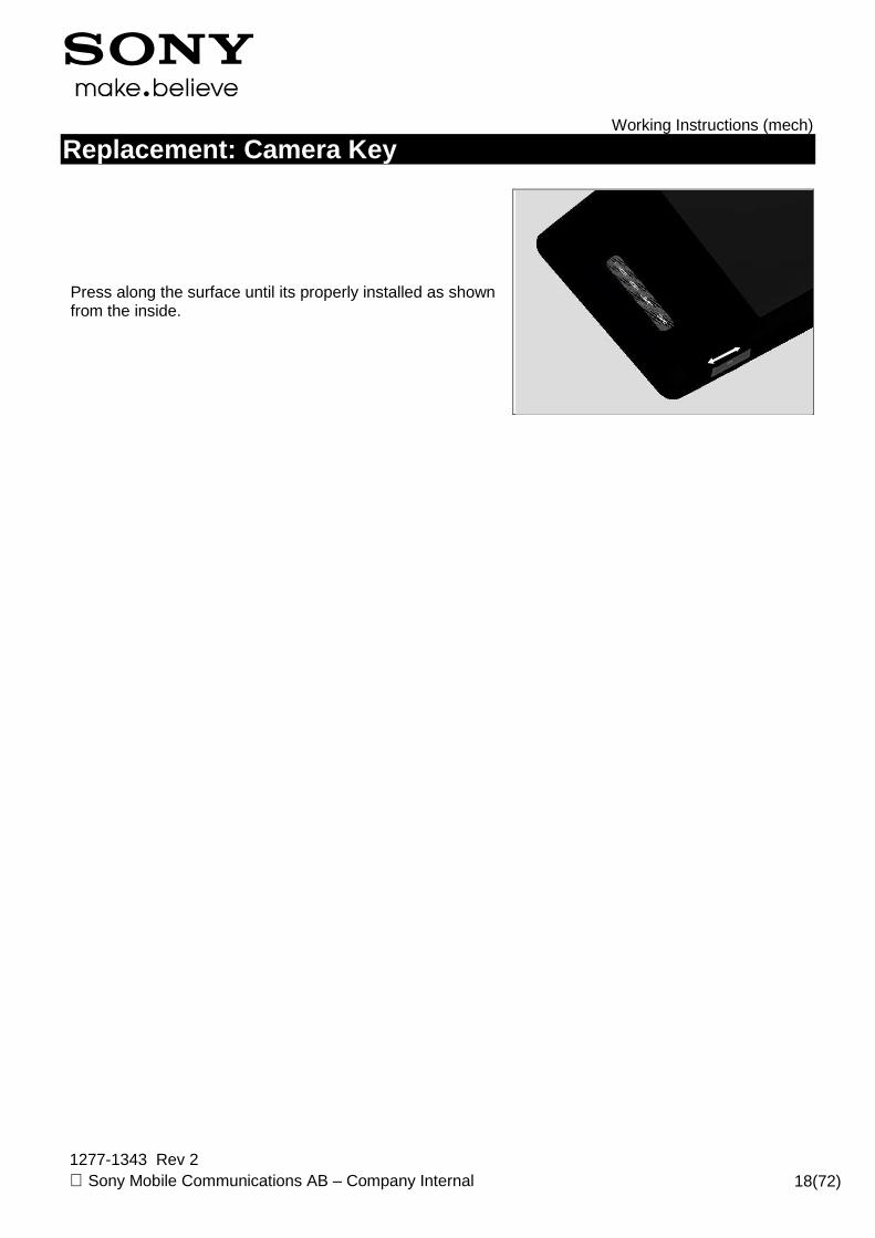
Replacement: Camera Key
Press along the surface until its properly installed as shown from the inside.

Working Instructions (mech)
1277-1343 Rev 2 Sony Mobile Communications AB – Company Internal 19(72)
Replacement
4.5 Coaxial Cable
Follow the 3.1 – 3.4 Disassembly instructions! Carry out the Removal as described below! Prepare the new Coaxial Cable. Carry out the Installation as described below! Follow the 5.2 – 5.5 Reassembly instructions!
REMOVAL Release the coax connector on the ANT Board side by using the Front Opening Tool.
Pull the Coaxial Cable to release it from Main PBA side.
INSTALLATION Place the Coaxial Cable in place.

Working Instructions (mech)
1277-1343 Rev 2 Sony Mobile Communications AB – Company Internal 20(72)
Replacement:Coaxial Cable
Put the Coaxial Cable into the cavity and press as shown place to fix the Coaxial Cable.
Press along the Coaxial Cable to secure the place.
Connect the coax connector on the ANT Board side as shown.

Working Instructions (mech)
1277-1343 Rev 2 Sony Mobile Communications AB – Company Internal 21(72)
Replacement
4.6 Diffusion Film
Follow the 3.1 – 3.3, 3.5 Disassembly instructions! Follow the 4.13, 4.22 Removal instructions! Carry out the Removal as described below! Prepare the new Diffusion Film. Carry out the Installation as described below! Follow the 4.13, 4.22 Installation instructions! Follow the 5.1, 5.3 – 5.5 Reassembly instructions!
REMOVAL Detach to remove it from Front Cover Assy.
INSTALLATION Place the Diffusion Film into the cavity.
Press long to secure its attached firmly.
Working Instructions (mech)
1277-1343 Rev 2 Sony Mobile Communications AB – Company Internal 22(72)
Replacement
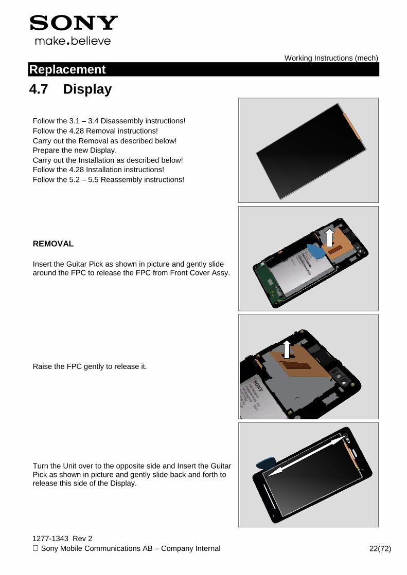
4.7 Display
Follow the 3.1 – 3.4 Disassembly instructions! Follow the 4.28 Removal instructions! Carry out the Removal as described below! Prepare the new Display. Carry out the Installation as described below! Follow the 4.28 Installation instructions! Follow the 5.2 – 5.5 Reassembly instructions!
REMOVAL Insert the Guitar Pick as shown in picture and gently slide around the FPC to release the FPC from Front Cover Assy.
Raise the FPC gently to release it.
Turn the Unit over to the opposite side and Insert the Guitar Pick as shown in picture and gently slide back and forth to release this side of the Display.
Working Instructions (mech)
1277-1343 Rev 2 Sony Mobile Communications AB – Company Internal 23(72)
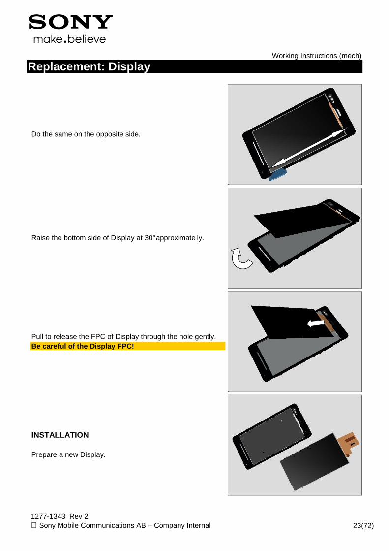
Replacement: Display
Do the same on the opposite side.
Raise the bottom side of Display at 30° approximate ly.
Pull to release the FPC of Display through the hole gently. Be careful of the Display FPC!
INSTALLATION Prepare a new Display.
Working Instructions (mech)
1277-1343 Rev 2 Sony Mobile Communications AB – Company Internal 24(72)
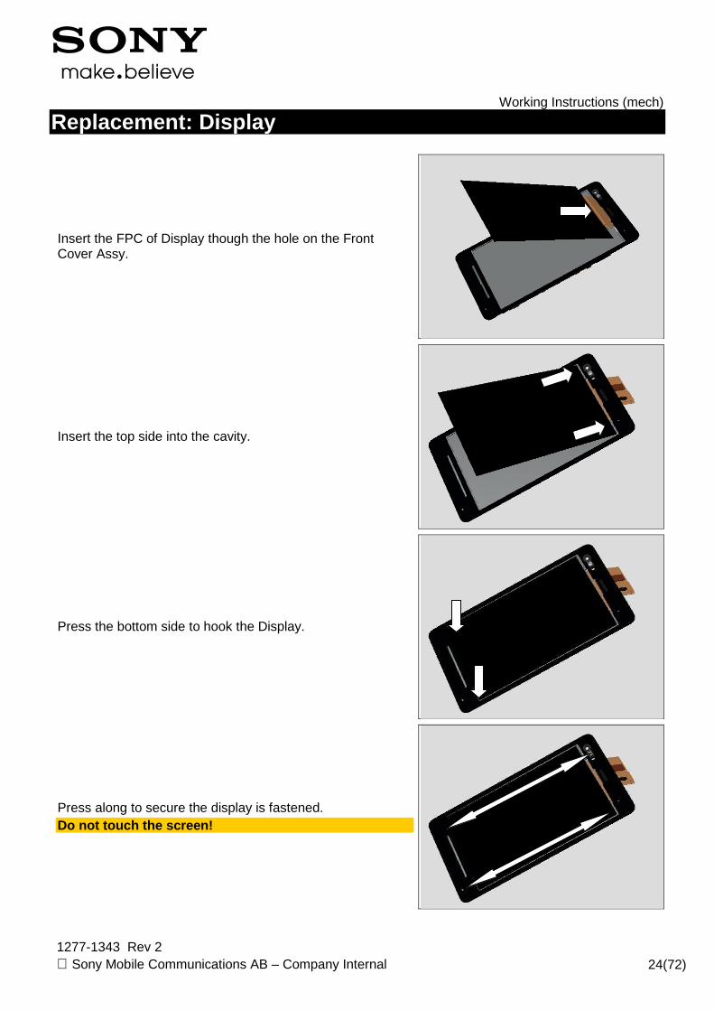
Replacement: Display
Insert the FPC of Display though the hole on the Front Cover Assy.
Insert the top side into the cavity.
Press the bottom side to hook the Display.
Press along to secure the display is fastened. Do not touch the screen!
Working Instructions (mech)
1277-1343 Rev 2 Sony Mobile Communications AB – Company Internal 25(72)
Replacement: Display
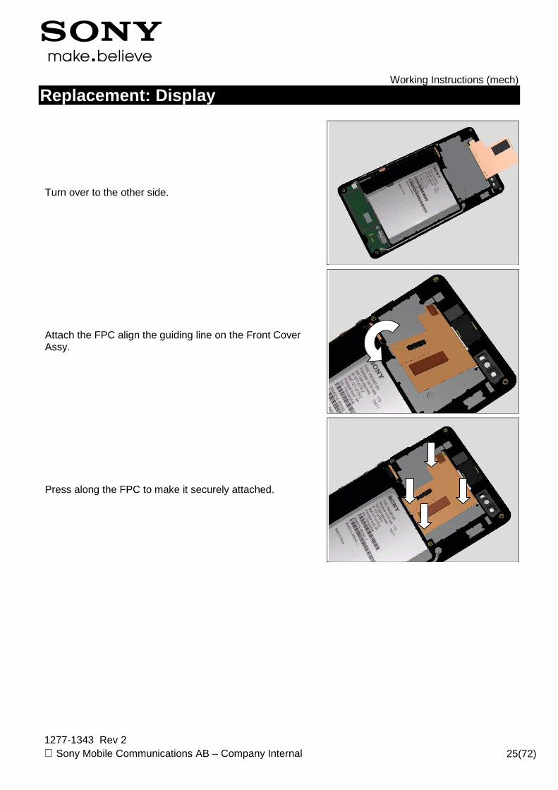
Turn over to the other side.
Attach the FPC align the guiding line on the Front Cover Assy.
Press along the FPC to make it securely attached.
Working Instructions (mech)
1277-1343 Rev 2 Sony Mobile Communications AB – Company Internal 26(72)
Replacement
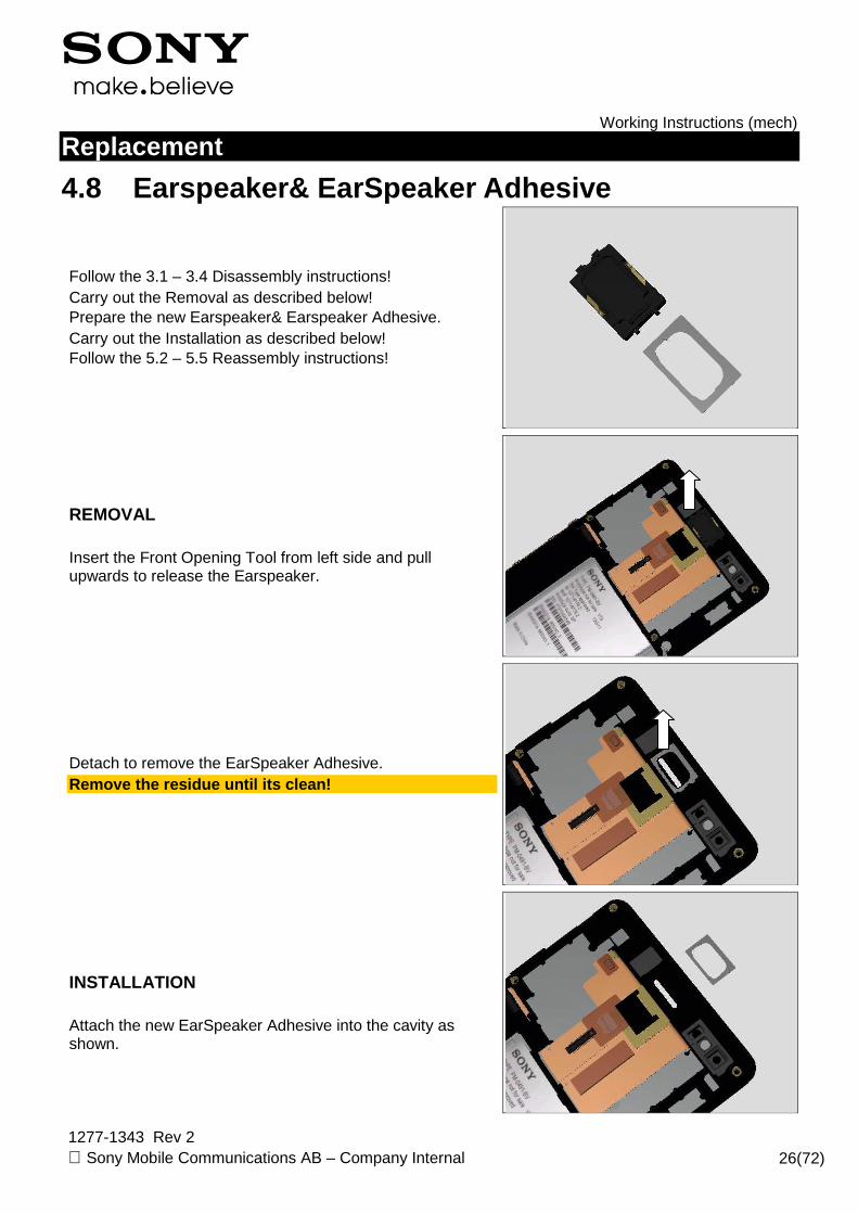
4.8 Earspeaker& EarSpeaker Adhesive
Follow the 3.1 – 3.4 Disassembly instructions! Carry out the Removal as described below! Prepare the new Earspeaker& Earspeaker Adhesive. Carry out the Installation as described below! Follow the 5.2 – 5.5 Reassembly instructions!
REMOVAL Insert the Front Opening Tool from left side and pull upwards to release the Earspeaker.
Detach to remove the EarSpeaker Adhesive. Remove the residue until its clean!
INSTALLATION Attach the new EarSpeaker Adhesive into the cavity as shown.

Working Instructions (mech)
1277-1343 Rev 2 Sony Mobile Communications AB – Company Internal 27(72)
Replacement: EarSpeaker & EarSpeaker Adhesive
Note the orientation of the EarSpeaker to be installed.
Place the EarSpeaker into the cavity and press the surface to secure its attachment. Do not touch the pins!
Working Instructions (mech)
1277-1343 Rev 2 Sony Mobile Communications AB – Company Internal 28(72)
Replacement
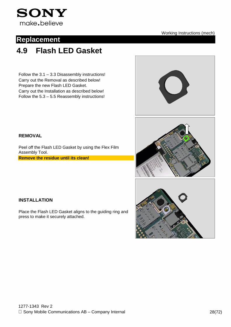
4.9 Flash LED Gasket
Follow the 3.1 – 3.3 Disassembly instructions! Carry out the Removal as described below! Prepare the new Flash LED Gasket. Carry out the Installation as described below! Follow the 5.3 – 5.5 Reassembly instructions!
REMOVAL Peel off the Flash LED Gasket by using the Flex Film Assembly Tool. Remove the residue until its clean!
INSTALLATION Place the Flash LED Gasket aligns to the guiding ring and press to make it securely attached.
Working Instructions (mech)
1277-1343 Rev 2 Sony Mobile Communications AB – Company Internal 29(72)
Replacement
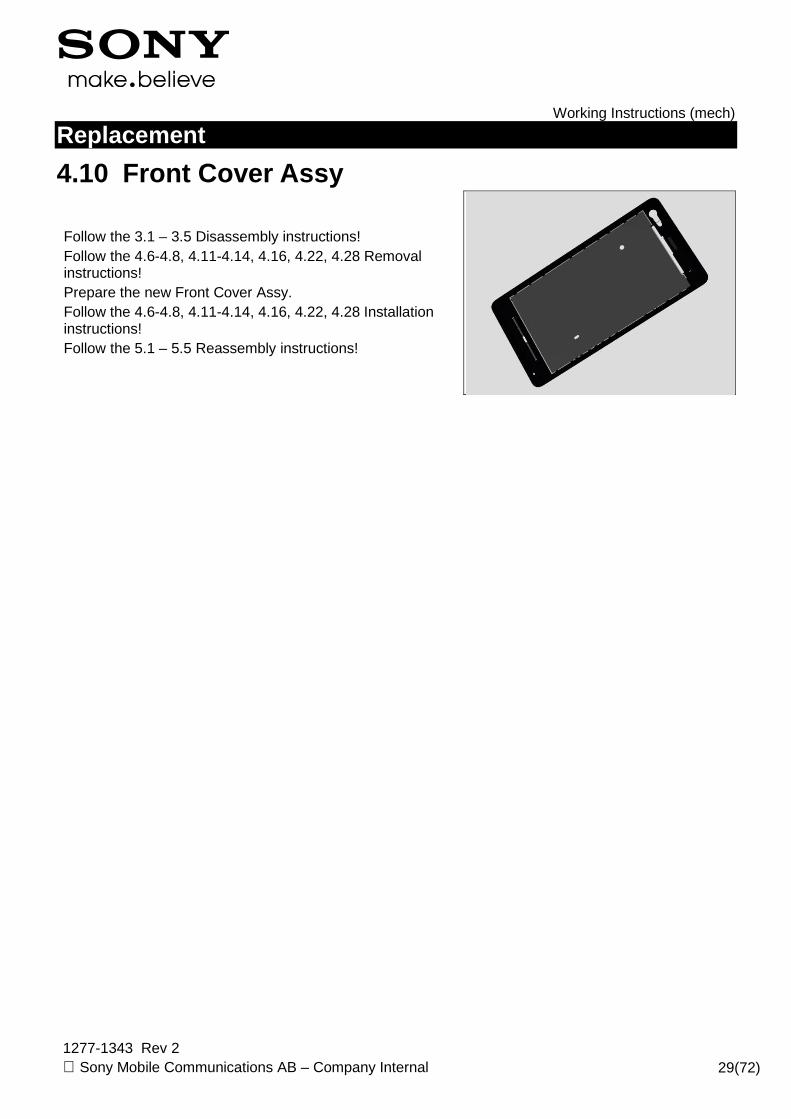
4.10 Front Cover Assy
Follow the 3.1 – 3.5 Disassembly instructions! Follow the 4.6-4.8, 4.11-4.14, 4.16, 4.22, 4.28 Removal instructions! Prepare the new Front Cover Assy. Follow the 4.6-4.8, 4.11-4.14, 4.16, 4.22, 4.28 Installation instructions! Follow the 5.1 – 5.5 Reassembly instructions!
Working Instructions (mech)
1277-1343 Rev 2 Sony Mobile Communications AB – Company Internal 30(72)
Replacement
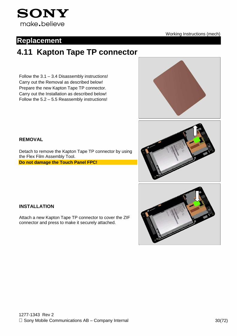
4.11 Kapton Tape TP connector
Follow the 3.1 – 3.4 Disassembly instructions! Carry out the Removal as described below! Prepare the new Kapton Tape TP connector. Carry out the Installation as described below! Follow the 5.2 – 5.5 Reassembly instructions!
REMOVAL Detach to remove the Kapton Tape TP connector by using the Flex Film Assembly Tool. Do not damage the Touch Panel FPC!
INSTALLATION Attach a new Kapton Tape TP connector to cover the ZIF connector and press to make it securely attached.
Working Instructions (mech)
1277-1343 Rev 2 Sony Mobile Communications AB – Company Internal 31(72)
Replacement
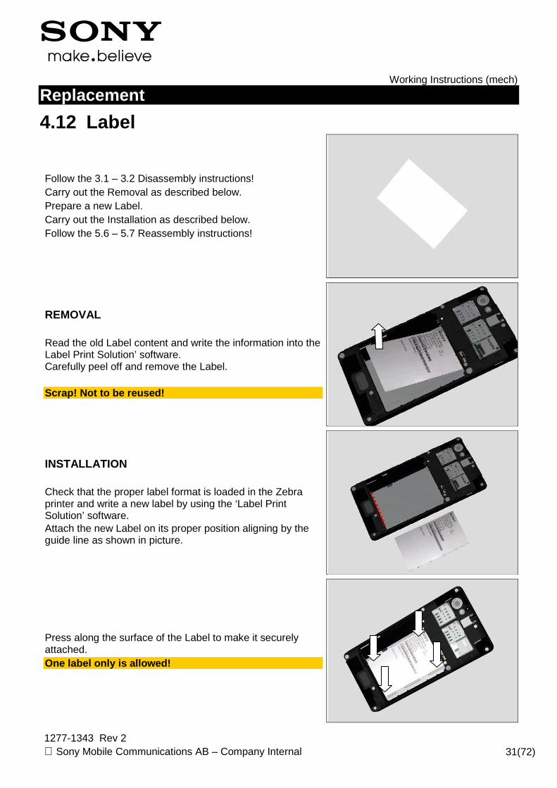
4.12 Label
Follow the 3.1 – 3.2 Disassembly instructions! Carry out the Removal as described below. Prepare a new Label. Carry out the Installation as described below. Follow the 5.6 – 5.7 Reassembly instructions!
REMOVAL Read the old Label content and write the information into the Label Print Solution’ software. Carefully peel off and remove the Label. Scrap! Not to be reused!
INSTALLATION Check that the proper label format is loaded in the Zebra printer and write a new label by using the ‘Label Print Solution’ software. Attach the new Label on its proper position aligning by the guide line as shown in picture.
Press along the surface of the Label to make it securely attached. One label only is allowed!
Working Instructions (mech)
1277-1343 Rev 2 Sony Mobile Communications AB – Company Internal 32(72)
Replacement
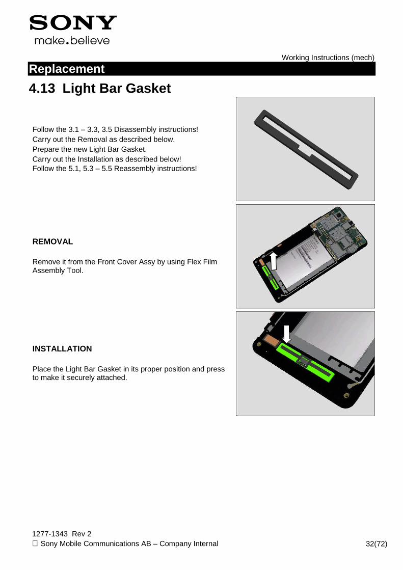
4.13 Light Bar Gasket
Follow the 3.1 – 3.3, 3.5 Disassembly instructions! Carry out the Removal as described below. Prepare the new Light Bar Gasket. Carry out the Installation as described below! Follow the 5.1, 5.3 – 5.5 Reassembly instructions!
REMOVAL Remove it from the Front Cover Assy by using Flex Film Assembly Tool.
INSTALLATION Place the Light Bar Gasket in its proper position and press to make it securely attached.
Working Instructions (mech)
1277-1343 Rev 2 Sony Mobile Communications AB – Company Internal 33(72)
Replacement
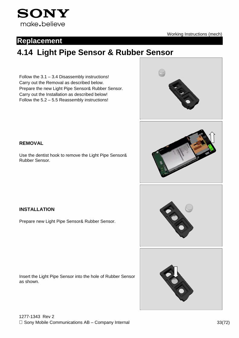
4.14 Light Pipe Sensor & Rubber Sensor
Follow the 3.1 – 3.4 Disassembly instructions! Carry out the Removal as described below. Prepare the new Light Pipe Sensor& Rubber Sensor. Carry out the Installation as described below! Follow the 5.2 – 5.5 Reassembly instructions!
REMOVAL Use the dentist hook to remove the Light Pipe Sensor& Rubber Sensor.
INSTALLATION Prepare new Light Pipe Sensor& Rubber Sensor.
Insert the Light Pipe Sensor into the hole of Rubber Sensor as shown.
Working Instructions (mech)
1277-1343 Rev 2 Sony Mobile Communications AB – Company Internal 34(72)
Replacement: Light Pipe Sensor & Rubber Sensor
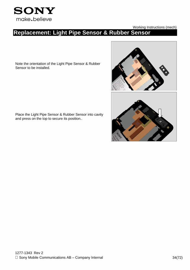
Note the orientation of the Light Pipe Sensor & Rubber Sensor to be installed.
Place the Light Pipe Sensor & Rubber Sensor into cavity and press on the top to secure its position..

Working Instructions (mech)
1277-1343 Rev 2 Sony Mobile Communications AB – Company Internal 35(72)
Replacement
4.15 Link FPC & Link FPC Gasket
Follow the 3.1 – 3.5 Disassembly instructions! Carry out the Removal as described below. Prepare the new Link FPC & Link FPC Gasket. Carry out the Installation as described below! Follow the 5.1 – 5.5 Reassembly instructions!
REMOVAL Use the Front Opening Tool to release the Side Key part of Link FPC from the Front Cover Assy gently.
Use the Front Opening Tool to release the Link FPC from the Front Cover Assy. Make sure no residue remains on the Front Cover Ass y!
INSTALLATION Attach a new Link FPC Gasket on the back side of BtB connector.

Working Instructions (mech)
1277-1343 Rev 2 Sony Mobile Communications AB – Company Internal 36(72)
Replacement: Link FPC & Link FPC Gasket
Press to secure its position.
Place the Link FPC Gasket B into its corresponding position as guiding shown in the picture.
Attach the Side Key FPC according to guiding poles as shown.
Press along the side key part of the Link FPC gently to make it securely attached.

Working Instructions (mech)
1277-1343 Rev 2 Sony Mobile Communications AB – Company Internal 37(72)
Replacement: Link FPC & Link FPC Gasket
Do the same to the rest part of Link FPC.

Working Instructions (mech)
1277-1343 Rev 2 Sony Mobile Communications AB – Company Internal 38(72)
Replacement
4.16 Link FPC Gasket B
Follow the 3.1 – 3.3, 3.5 Disassembly instructions! Carry out the Removal as described below. Prepare the new Link FPC Gasket B. Carry out the Installation as described below! Follow the 5.1, 5.3 – 5.5 Reassembly instructions!
REMOVAL Detach to remove it by using tweezers.
INSTALLATION Place the Link FPC Gasket B into its corresponding position
Press to secure its position.

Working Instructions (mech)
1277-1343 Rev 2 Sony Mobile Communications AB – Company Internal 39(72)
Replacement
4.17 Loudspeaker & Speaker Gasket
Follow the 3.1 – 3.3 Disassembly instructions! Carry out the Removal as described below. Prepare the new Loudspeaker & Speaker Gasket. Carry out the Installation as described below! Follow the 5.3 – 5.5 Reassembly instructions!
REMOVAL Insert the Front Opening Tool from left side and pull upwards to release the Loudspeaker.
Detach to remove the Speaker Adhesive. Remove the residue until its clean!
INSTALLATION Attach the new Speaker Adhesive into the cavity as shown.
Working Instructions (mech)
1277-1343 Rev 2 Sony Mobile Communications AB – Company Internal 40(72)
Replacement: Loudspeaker & Speaker Gasket
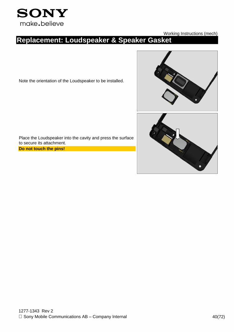
Note the orientation of the Loudspeaker to be installed.
Place the Loudspeaker into the cavity and press the surface to secure its attachment. Do not touch the pins!
Working Instructions (mech)
1277-1343 Rev 2 Sony Mobile Communications AB – Company Internal 41(72)
Replacement
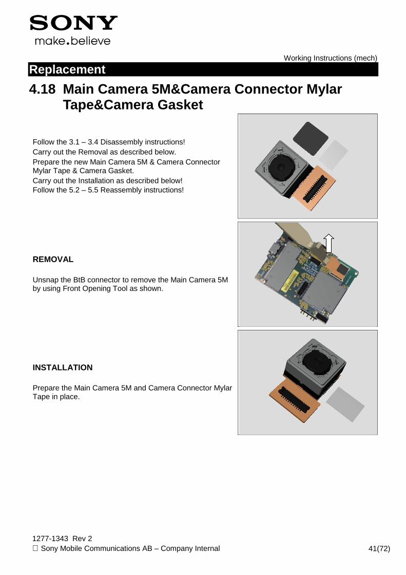
4.18 Main Camera 5M &Camera Connector Mylar Tape&Camera Gasket
Follow the 3.1 – 3.4 Disassembly instructions! Carry out the Removal as described below. Prepare the new Main Camera 5M & Camera Connector Mylar Tape & Camera Gasket. Carry out the Installation as described below! Follow the 5.2 – 5.5 Reassembly instructions!
REMOVAL Unsnap the BtB connector to remove the Main Camera 5M by using Front Opening Tool as shown.
INSTALLATION Prepare the Main Camera 5M and Camera Connector Mylar Tape in place.

Working Instructions (mech)
1277-1343 Rev 2 Sony Mobile Communications AB – Company Internal 42(72)
Replacement: Main Camera 5M & Camera Connector Myla r Tape & Camera Gasket
Attach the Camera Connector Mylar Tape onto the Main Camera 5M as shown.
Attach the Camera Gasket onto the bottom of the Main Camera 5M as shown.
Place the Main Camera 5M next to the Main PBA
Put the head of Main Camera 5M into the hole and press to snap the BtB connector as shown in the picture.

Working Instructions (mech)
1277-1343 Rev 2 Sony Mobile Communications AB – Company Internal 43(72)
Replacement
4.19 Microphone Rubber & Microphone Mesh
Follow the 3.1 – 3.3, 3.5 Disassembly instructions! Carry out the Removal as described below! Prepare the new Microphone Rubber & Microphone Mesh. Carry out the Installation as described below! Follow the 5.1, 5.3 – 5.5 Reassembly instructions!
REMOVAL Remove the Microphone Rubber by using Flex Film Assembly Tool.
Peel off the Microphone Mesh by using the Flex Film Assembly Tool. Remove the residue until its clean!
INSTALLATION Place the Microphone Mesh into its corresponding hole.

Working Instructions (mech)
1277-1343 Rev 2 Sony Mobile Communications AB – Company Internal 44(72)
Replacement: Microphone Rubber & Microphone Mesh
Press to secure its attachment.
Place the Microphone Rubber into its corresponding hole.
Press to secure its position.
Working Instructions (mech)
1277-1343 Rev 2 Sony Mobile Communications AB – Company Internal 45(72)
Replacement
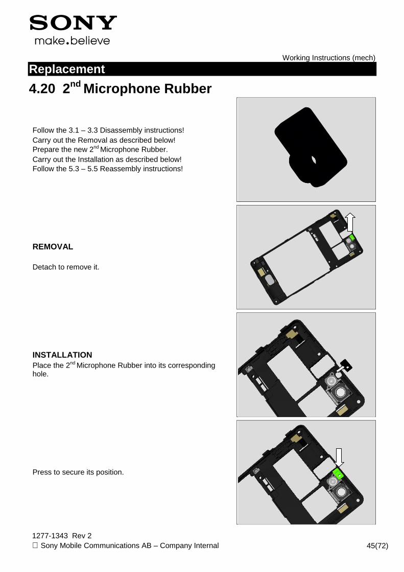
4.20 2nd Microphone Rubber
Follow the 3.1 – 3.3 Disassembly instructions! Carry out the Removal as described below! Prepare the new 2nd Microphone Rubber. Carry out the Installation as described below! Follow the 5.3 – 5.5 Reassembly instructions!
REMOVAL Detach to remove it.
INSTALLATION Place the 2nd Microphone Rubber into its corresponding hole.
Press to secure its position.
Working Instructions (mech)
1277-1343 Rev 2 Sony Mobile Communications AB – Company Internal 46(72)
Replacement
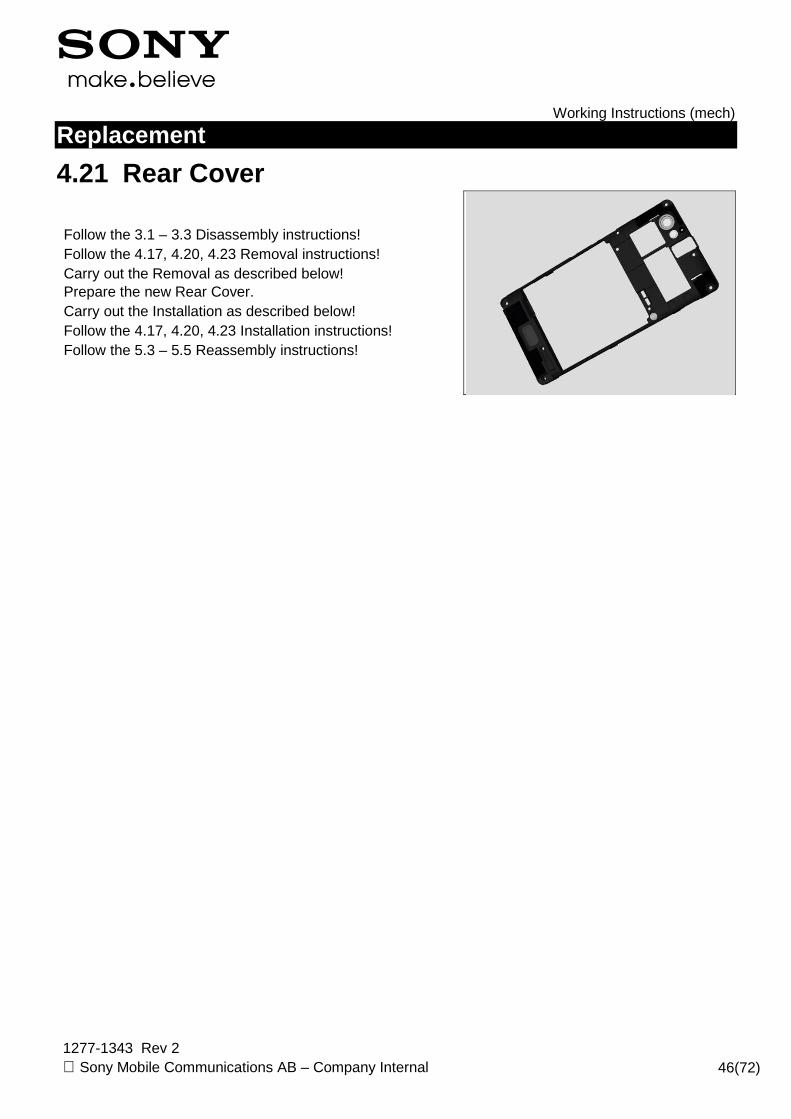
4.21 Rear Cover
Follow the 3.1 – 3.3 Disassembly instructions! Follow the 4.17, 4.20, 4.23 Removal instructions! Carry out the Removal as described below! Prepare the new Rear Cover. Carry out the Installation as described below! Follow the 4.17, 4.20, 4.23 Installation instructions! Follow the 5.3 – 5.5 Reassembly instructions!

Working Instructions (mech)
1277-1343 Rev 2 Sony Mobile Communications AB – Company Internal 47(72)
Replacement
4.22 Reflective Sheet
Follow the 3.1 – 3.3, 3.5 Disassembly instructions! Carry out the Removal as described below! Prepare the new Reflective Sheet. Carry out the Installation as described below! Follow the 5.1, 5.3 – 5.5 Reassembly instructions!
REMOVAL Detach to remove it by using tweezers.
INSTALLATION Place the Reflective Sheet into its corresponding position
Press to secure its position.
Working Instructions (mech)
1277-1343 Rev 2 Sony Mobile Communications AB – Company Internal 48(72)
Replacement
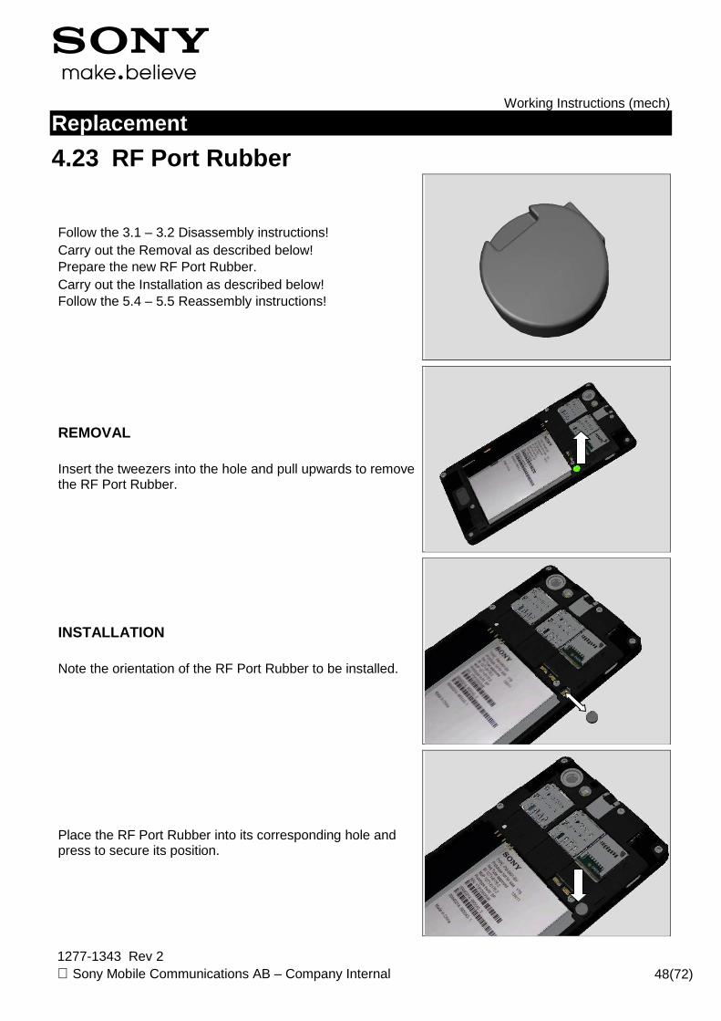
4.23 RF Port Rubber
Follow the 3.1 – 3.2 Disassembly instructions! Carry out the Removal as described below! Prepare the new RF Port Rubber. Carry out the Installation as described below! Follow the 5.4 – 5.5 Reassembly instructions!
REMOVAL Insert the tweezers into the hole and pull upwards to remove the RF Port Rubber.
INSTALLATION Note the orientation of the RF Port Rubber to be installed.
Place the RF Port Rubber into its corresponding hole and press to secure its position.

Working Instructions (mech)
1277-1343 Rev 2 Sony Mobile Communications AB – Company Internal 49(72)
Replacement
4.24 SIM Board & SIM Board Adhesive
Follow the 3.1 – 3.3 Disassembly instructions! Carry out the Removal as described below! Prepare the new SIM Board & SIM Board Adhesive Carry out the Installation as described below! Follow the 4.9 Installation instructions! Follow the 5.3 – 5.5 Reassembly instructions!
REMOVAL Insert the Guitar Pick underneath the SIM Board and pull gently upwards to release it from left side.
Release the BtB connector.
Remove the SIM Board from Main PBA.
Working Instructions (mech)
1277-1343 Rev 2 Sony Mobile Communications AB – Company Internal 50(72)
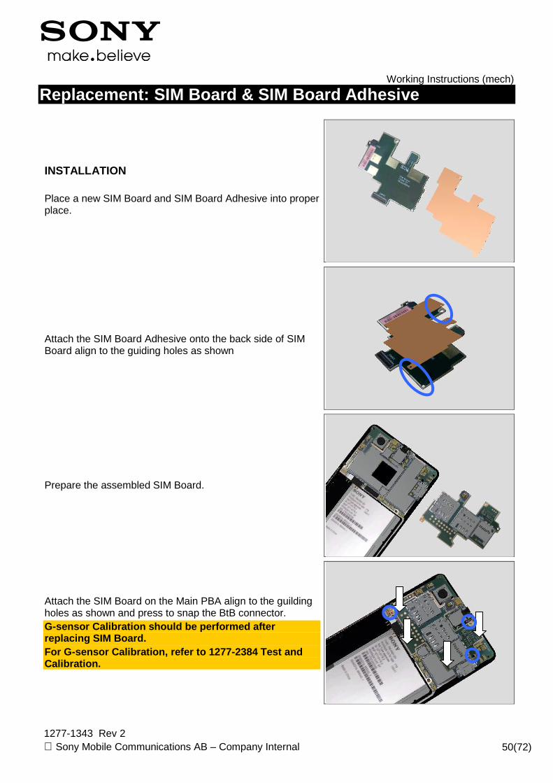
Replacement: SIM Board & SIM Board Adhesive
INSTALLATION Place a new SIM Board and SIM Board Adhesive into proper place.
Attach the SIM Board Adhesive onto the back side of SIM Board align to the guiding holes as shown
Prepare the assembled SIM Board.
Attach the SIM Board on the Main PBA align to the guilding holes as shown and press to snap the BtB connector. G-sensor Calibration should be performed after replacing SIM Board. For G-sensor Calibration, refer to 1277-2384 Test and Calibration.

Working Instructions (mech)
1277-1343 Rev 2 Sony Mobile Communications AB – Company Internal 51(72)
Replacement
4.25 Speaker Mesh
Follow the 3.1Disassembly instructions! Carry out the Removal as described below! Prepare the new Speaker Mesh. Carry out the Installation as described below! Follow the 5.5 Reassembly instructions!
REMOVAL Push from outside to release it by using tweezers.
INSTALLATION Attach a new Speaker Mesh align the frame.
Press to secure its attachment.

Working Instructions (mech)
1277-1343 Rev 2 Sony Mobile Communications AB – Company Internal 52(72)
Replacement
4.26 Speaker Mesh on Rear Cover
Follow the 3.1 – 3.2 Disassembly instructions! Carry out the Removal as described below! Prepare the new Speaker Mesh on Rear Cover. Carry out the Installation as described below! Follow the 5.4 – 5.5 Reassembly instructions!
REMOVAL Detach to remove it.
INSTALLATION Attach a new Speaker Mesh on Rear Cover align the frame.
Press to secure its attachment.

Working Instructions (mech)
1277-1343 Rev 2 Sony Mobile Communications AB – Company Internal 53(72)
Replacement
4.27 Speaker Sponge
Follow the 3.1 – 3.3 Disassembly instructions! Carry out the Removal as described below! Prepare the new Speaker Sponge. Carry out the Installation as described below! Follow the 5.3 – 5.5 Reassembly instructions!
REMOVAL Detach to remove it.
INSTALLATION Place a new Speaker Sponge in place.
Attach it onto the ANT Board align the frame and press along to secure the attachment.

Working Instructions (mech)
1277-1343 Rev 2 Sony Mobile Communications AB – Company Internal 54(72)
Replacement
4.28 Touch Panel & Touch Panel Adhesive
Follow the 3.1 – 3.5. Disassembly instructions! Carry out the Removal as described below! Follow the 4.7 Removal instructions! Prepare the new Touch Panel & Touch Panel Adhesive & Front Cover Assy. Follow the 4.7 Installation instructions Carry out the Installation as described below! Follow the 5.1 – 5.5. Reassembly instructions!
REMOVAL Detach to remove the Kapton Tape TP connector by using the Flex Film Assembly Tool. Do not damage the Touch Panel FPC!
Unlock the ZIF connector.
Release the Touch Panel FPC from ZIF connector and gently release it from adhesive underneath.

Working Instructions (mech)
1277-1343 Rev 2 Sony Mobile Communications AB – Company Internal 55(72)
Replacement: Touch Panel & Touch Panel Adhesive
Turn the Unit over to the other side.
Insert the Guitar Pick into the left bottom corner and slide to release the left side of Touch Panel. Be careful of the Front Cover Assy, If the Touch Pa nel cracks during this operation, stop to disassemble t he unit right away and reassemble with new parts!
Insert the Guitar Pick slide back and force to release the bottom side. Be careful of the Front Cover Assy, If the Touch Pa nel cracks during this operation, stop to disassemble t he unit right away and reassemble with new parts!
Do the same for another two sides as shown. Be careful of the Front Cover Assy, If the Touch Pa nel cracks during this operation, stop to disassemble t he unit right away and reassemble with new parts!

Working Instructions (mech)
1277-1343 Rev 2 Sony Mobile Communications AB – Company Internal 56(72)
Replacement: Touch Panel & Touch Panel Adhesive
Raise the bottom of the Touch Panel at 30° approxim ately to release the top side gently.
Pull to remove the Touch Panel FPC and the Touch Panel through the hole.
Remove the Touch Panel Adhesive and clean the residue until its clean. Make sure no residue remains!
INSTALLATION Put a new Touch Panel Adhesive in place.

Working Instructions (mech)
1277-1343 Rev 2 Sony Mobile Communications AB – Company Internal 57(72)
Replacement: Touch Panel & Touch Panel Adhesive
Attach the Touch Panel Adhesive align the LCD Frame firmly.
Place a new Touch Panel in place.
Insert the Touch Panel through the hole on the top side.
Place the top side of Touch Panel align the LCD Frame. Do not touch the Touch Panel Adhesive!

Working Instructions (mech)
1277-1343 Rev 2 Sony Mobile Communications AB – Company Internal 58(72)
Replacement: Touch Panel & Touch Panel Adhesive
Turn the Touch Panel back to horizontal position align the frame.
Press the surface to make it securely attached.
Turn over the Unit and insert the Touch Panel FPC into ZIF connector.
Lock the ZIF connector.
Working Instructions (mech)
1277-1343 Rev 2 Sony Mobile Communications AB – Company Internal 59(72)
Replacement: Touch Panel & Touch Panel Adhesive
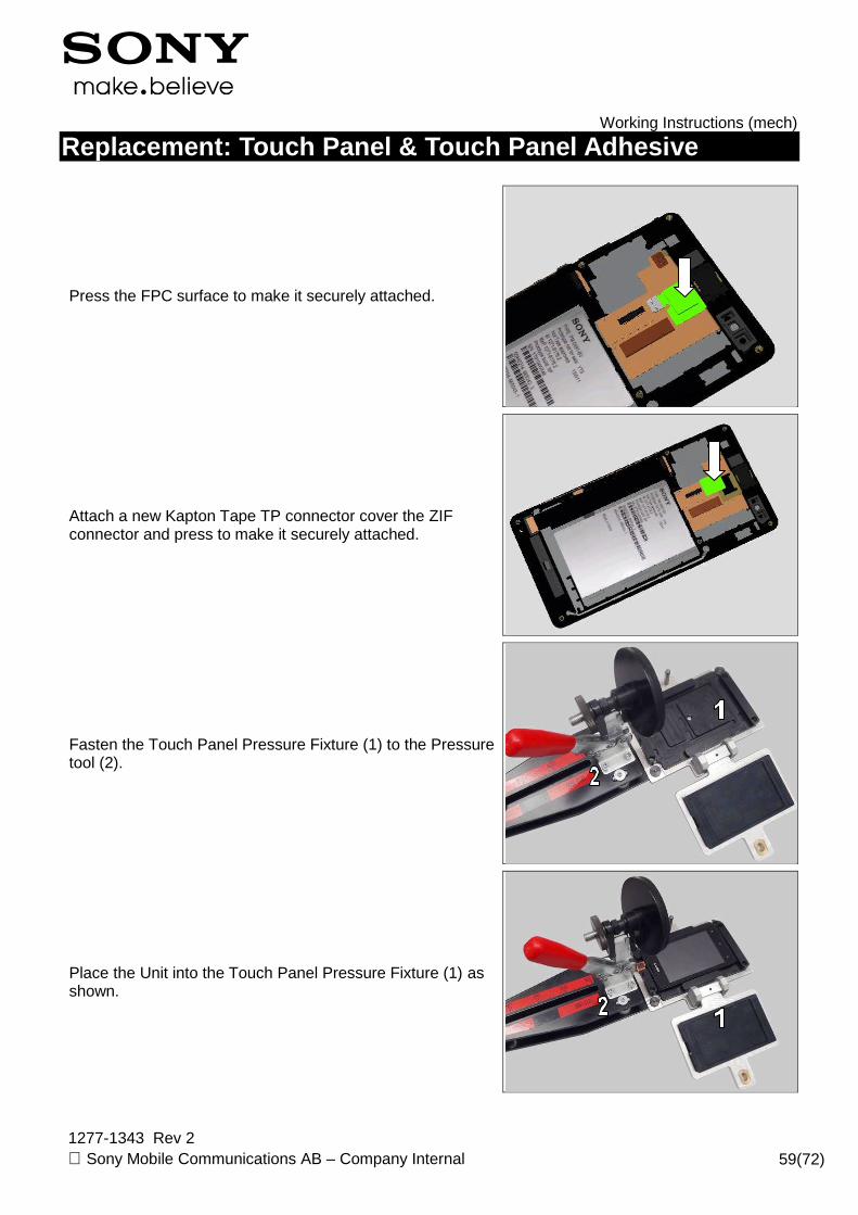
Press the FPC surface to make it securely attached.
Attach a new Kapton Tape TP connector cover the ZIF connector and press to make it securely attached.
Fasten the Touch Panel Pressure Fixture (1) to the Pressure tool (2).
Place the Unit into the Touch Panel Pressure Fixture (1) as shown.

Working Instructions (mech)
1277-1343 Rev 2 Sony Mobile Communications AB – Company Internal 60(72)
Replacement: Touch Panel & Touch Panel Adhesive
Fasten the Phone in the Touch Panel Pressure Fixture (1).
Press the handle of the Pressure Tool (2) with a pressure value of 220+/-20Ncm for 20seconds.
Make sure its four sides are securely pressed!
Working Instructions (mech)
1277-1343 Rev 2 Sony Mobile Communications AB – Company Internal 61(72)
Replacement
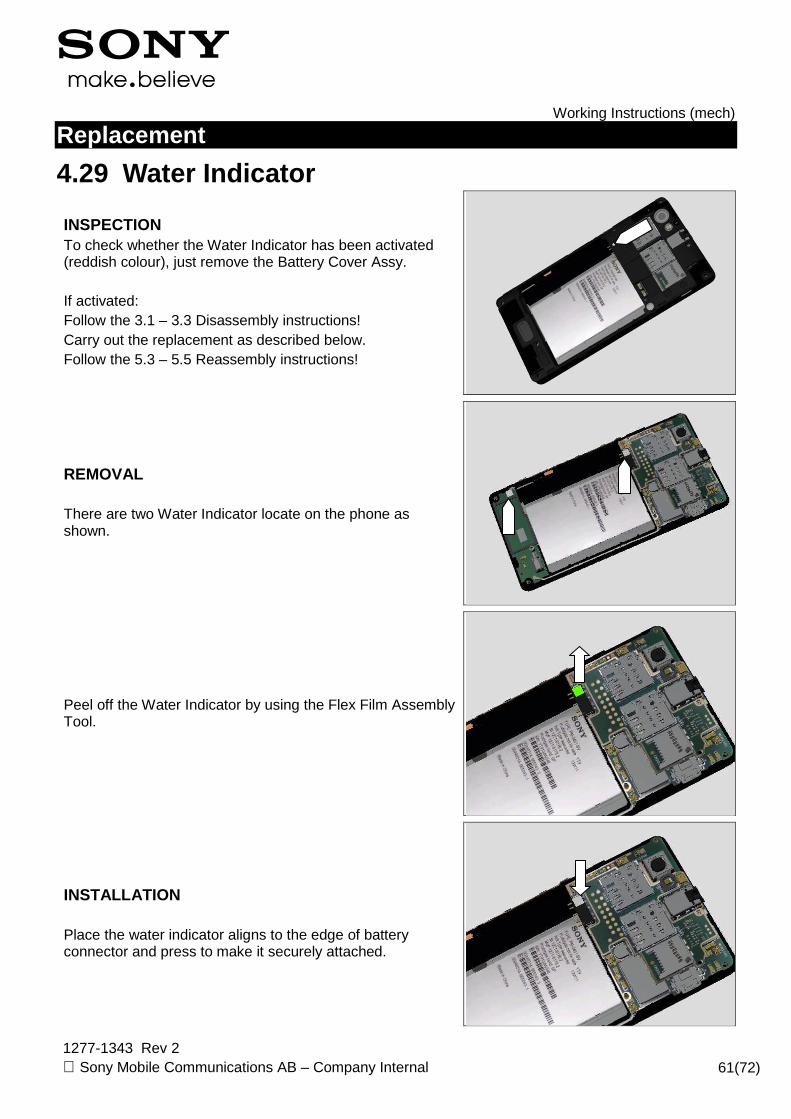
4.29 Water Indicator
INSPECTION To check whether the Water Indicator has been activated (reddish colour), just remove the Battery Cover Assy. If activated: Follow the 3.1 – 3.3 Disassembly instructions! Carry out the replacement as described below. Follow the 5.3 – 5.5 Reassembly instructions!
REMOVAL There are two Water Indicator locate on the phone as shown.
Peel off the Water Indicator by using the Flex Film Assembly Tool.
INSTALLATION Place the water indicator aligns to the edge of battery connector and press to make it securely attached.
Working Instructions (mech)
1277-1343 Rev 2 Sony Mobile Communications AB – Company Internal 62(72)
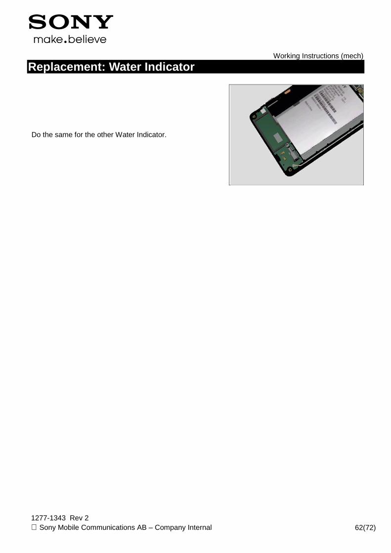
Replacement: Water Indicator
Do the same for the other Water Indicator.
Working Instructions (mech)
1277-1343 Rev 2 Sony Mobile Communications AB – Company Internal 63(72)
Replacement
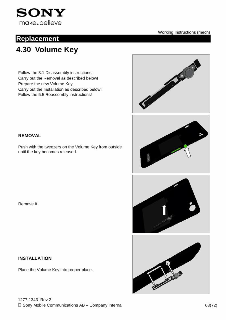
4.30 Volume Key
Follow the 3.1 Disassembly instructions! Carry out the Removal as described below! Prepare the new Volume Key. Carry out the Installation as described below! Follow the 5.5 Reassembly instructions!
REMOVAL Push with the tweezers on the Volume Key from outside until the key becomes released.
Remove it.
INSTALLATION Place the Volume Key into proper place.

Working Instructions (mech)
1277-1343 Rev 2 Sony Mobile Communications AB – Company Internal 64(72)
Replacement: Volume Key
Press along the surface until its properly installed as shown from the inside.
1277-1343 Rev 2 Sony Mobile Communications AB
Replacement
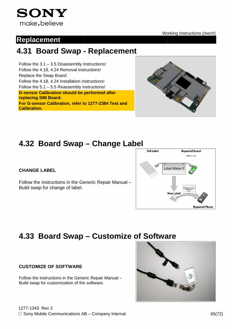
4.31 Board Swap -
Follow the 3.1 – 3.5 Disassembly instructions!Follow the 4.18, 4.24 Removal instructions!Replace the Swap Board. Follow the 4.18, 4.24 Installation instructions!Follow the 5.1 – 5.5 Reassembly instructions!G-sensor Calibration should be performed after replacing SIM Board. For G-sensor Calibration , refer toCalibration.
4.32 Board Swap
CHANGE LABEL Follow the instructions in the Generic Repair Manual Build swap for change of label.
4.33 Board Swap
CUSTOMIZE OF SOFTWARE Follow the instructions in the Generic Repair Manual Build swap for customization of the software.
Working Instructions (mech)
Sony Mobile Communications AB – Company Internal
- Replacement
Disassembly instructions! Follow the 4.18, 4.24 Removal instructions!
instructions! Reassembly instructions!
sensor Calibration should be performed after
, refer to 1277-2384 Test and
Board Swap – Change Label
e Generic Repair Manual –
Board Swap – Customize of Software
Follow the instructions in the Generic Repair Manual – swap for customization of the software.
Working Instructions (mech)
65(72)
Software
Working Instructions (mech)
1277-1343 Rev 2 Sony Mobile Communications AB – Company Internal 66(72)
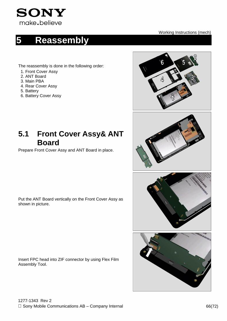
5 Reassembly
The reassembly is done in the following order: 1. Front Cover Assy 2. ANT Board 3. Main PBA 4. Rear Cover Assy 5. Battery 6. Battery Cover Assy
5.1 Front Cover Assy& ANT Board
Prepare Front Cover Assy and ANT Board in place.
Put the ANT Board vertically on the Front Cover Assy as shown in picture.
Insert FPC head into ZIF connector by using Flex Film Assembly Tool.
Working Instructions (mech)
1277-1343 Rev 2 Sony Mobile Communications AB – Company Internal 67(72)
Reassembly
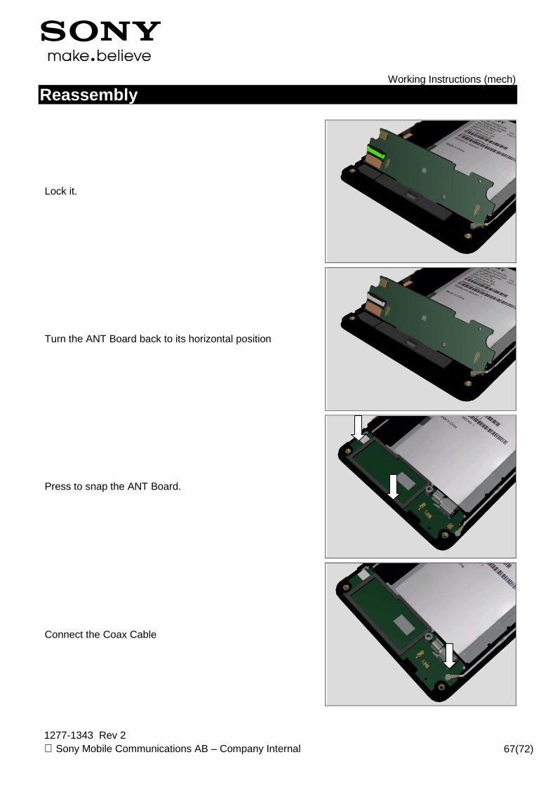
Lock it.
Turn the ANT Board back to its horizontal position
Press to snap the ANT Board.
Connect the Coax Cable
Working Instructions (mech)
1277-1343 Rev 2 Sony Mobile Communications AB – Company Internal 68(72)
Reassembly
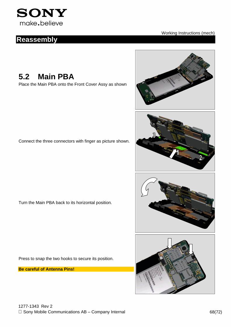
5.2 Main PBA Place the Main PBA onto the Front Cover Assy as shown
Connect the three connectors with finger as picture shown.
Turn the Main PBA back to its horizontal position.
Press to snap the two hooks to secure its position. Be careful of Antenna Pins!

Working Instructions (mech)
1277-1343 Rev 2 Sony Mobile Communications AB – Company Internal 69(72)
Reassembly
5.3 Rear Cover Assy Place the Rear Cover Assy on top of the Main PBA in its proper position.
Press the four sides to snap.
Apply 7~9 Ncm torque when tightening the Screw M1.4*2.4 with Bits (JCIS No 0).
Apply 7~9 Ncm torque when tightening Screw M1.6*3.0 with Bits (T5).

Working Instructions (mech)
1277-1343 Rev 2 Sony Mobile Communications AB – Company Internal 70(72)
Reassembly
Apply 7~9 Ncm torque when tightening the six screws M1.6*4.0 with Bits (T5).
5.4 Battery Insert the Battery at the top like this.
Press at the bottom to secure its position.
5.5 Battery Cover Assy Prepare the Battery Cover Assy at its proper position as shown.

Working Instructions (mech)
1277-1343 Rev 2 Sony Mobile Communications AB – Company Internal 71(72)
Reassembly
Press the four sides to snap the Battery Cover Assy.
Working Instructions (mech)
1277-1343 Rev 2 Sony Mobile Communications AB – Company Internal 72(72)
6 Revision History
Rev. Date Changes / Comments 1 2013-Aug-09 Initial release
2 2013-Sep-02 Update 4.28 Touch Panel chapter with both disassembly and reassembly