xr4400_p0050_m_en.pdf
TRANSCRIPT
8122019 XR4400_P0050_M_ENpdf
httpslidepdfcomreaderfullxr4400p0050menpdf 114
User Manual
MULTIGATE PRO XR4400
Reference-Class 4-Channel ExpanderGate
8122019 XR4400_P0050_M_ENpdf
httpslidepdfcomreaderfullxr4400p0050menpdf 214
2 MULTIGATE PRO XR4400 User Manual
Table of ContentsImportant Safety Instructions 3
Legal Disclaimer 3
Limited warranty 3
1 Introduction 4
11 Technical background 4
2 The Design Concept 6
21 High quality components and design 6
22 Inputs and outputs 6
3 Installation 6
31 Rack mounting 6
32 Mains voltage 6
33 Audio connections 6
4 Controls 7
41 The front panel control elements 742 The rear panel elements 8
5 Technical Background 8
51 EXPANDER mode 8
52 Interactive control functions 8
53 FLEXLINK function 10
54 The SIDECHAIN filter 10
6 Applications 10
61 Basic setting 10
62 Proper positioning of microphones 11
63 Applications 12
7 Specifications 12
8122019 XR4400_P0050_M_ENpdf
httpslidepdfcomreaderfullxr4400p0050menpdf 314
3 MULTIGATE PRO XR4400 User Manual
Important SafetyInstructions
LEGAL DISCLAIMER
LIMITED WARRANTY
Terminals marked with this symbol carryelectrical current of suffi cient magnitudeto constitute risk of electric shock
Use only high-quality professional speaker cables withfrac14 TS or twist-locking plugs pre-installed All otherinstallation or modification should be performed onlyby qualified personnel
This symbol wherever it appearsalerts you to the presence of uninsulateddangerous voltage inside the
enclosure - voltage that may be suffi cient to constitute arisk of shock
This symbol wherever it appearsalerts you to important operating andmaintenance instructions in the
accompanying literature Please read the manual
Caution
To reduce the risk of electric shock do notremove the top cover (or the rear section)
No user serviceable parts inside Refer servicing toqualified personnel
Caution
To reduce the risk of fire or electric shockdo not expose this appliance to rain and
moisture The apparatus shall not be exposed to drippingor splashing liquids and no objects filled with liquidssuch as vases shall be placed on the apparatus
Caution
These service instructions are for useby qualified service personnel only
To reduce the risk of electric shock do not perform anyservicing other than that contained in the operationinstructions Repairs have to be performed by qualifiedservice personnel
1 Read these instructions
2 Keep these instructions
3 Heed all warnings
4 Follow all instructions
5 Do not use this apparatus near water
6 Clean only with dry cloth
7 Do not block any ventilation openings Install inaccordance with the manufacturerrsquos instructions
8 Do not install near any heat sources such asradiators heat registers stoves or other apparatus(including amplifiers) that produce heat
9 Do not defeat the safety purpose of the polarizedor grounding-type plug A polarized plug has two bladeswith one wider than the other A grounding-type plughas two blades and a third grounding prong The wideblade or the third prong are provided for your safety If theprovided plug does not fit into your outlet consult anelectrician for replacement of the obsolete outlet
10 Protect the power cord from being walked on orpinched particularly at plugs convenience receptaclesand the point where they exit from the apparatus
11 Use only attachmentsaccessories specified bythe manufacturer
12 Use only with thecart stand tripod bracketor table specified by themanufacturer or sold withthe apparatus When a cartis used use caution whenmoving the cartapparatuscombination to avoid
injury from tip-over
13 Unplug this apparatus during lightning storms orwhen unused for long periods of time
14 Refer all servicing to qualified service personnelServicing is required when the apparatus has beendamaged in any way such as power supply cord or plugis damaged liquid has been spilled or objects have falleninto the apparatus the apparatus has been exposedto rain or moisture does not operate normally or hasbeen dropped
15 The apparatus shall be connected to a MAINS socketoutlet with a protective earthing connection
16 Where the MAINS plug or an appliance coupler is
used as the disconnect device the disconnect device shallremain readily operable
TECHNICAL SPECIFICATIONS AND APPEARANCESARE SUBJECT TO CHANGE WITHOUT NOTICE ANDACCURACY IS NOT GUARANTEED BEHRINGERKLARK TEKNIK MIDAS BUGERA AND TURBOSOUNDARE PART OF THE MUSIC GROUP 983080MUSIC983085GROUPCOM983081ALL TRADEMARKS ARE THE PROPERTY OF THEIRRESPECTIVE OWNERS MUSIC GROUP ACCEPTS NOLIABILITY FOR ANY LOSS WHICH MAY BE SUFFEREDBY ANY PERSON WHO RELIES EITHER WHOLLY ORIN PART UPON ANY DESCRIPTION PHOTOGRAPHOR STATEMENT CONTAINED HEREIN COLORS ANDSPECIFICATIONS MAY VARY FROM ACTUAL PRODUCTMUSIC GROUP PRODUCTS ARE SO LD THROUGH
AUTHORIZED FULLFILLERS AND RESELLERS O NLYFULLFILLERS AND RESELLERS ARE NOT AGENTS OFMUSIC GROUP AND HAVE ABSOLUTELY NO AUTHORITY
TO BIND MUSIC GROUP BY ANY EXPRESS OR IMPLI EDUNDERTAKING OR REPRESENTATION THIS MANUALIS COPYRIGHTED NO PART OF THIS MANUAL MAYBE REPRODUCED OR TRANSMITTED IN ANY FORMOR BY ANY MEANS ELECTRONIC OR MECHANICALINCLUDING PHOTOCOPYING AND RECORDING OF ANYKIND FOR ANY PURPOSE WITHOUT THE EXPRESSWRITTEN PERMISSION OF MUSI C GROUP IP LTD
ALL RIGHTS RESERVEDcopy 2013 MUSIC Group IP LtdTrident Chambers Wickhams Cay PO Box 146Road Town Tortola British Virgin Islands
For the applicable warranty terms and conditionsand additional information regarding MUSIC GrouprsquosLimited Warranty please see complete details online atwwwmusic-groupcomwarranty
8122019 XR4400_P0050_M_ENpdf
httpslidepdfcomreaderfullxr4400p0050menpdf 414
4 MULTIGATE PRO XR4400 User Manual
1 IntroductionWith the BEHRINGER MULTIGATE PRO you purchased a dynamics processor of thehigh-end class designed to meet highest requirements professional recordingbroadcast and television studios CD and digital production facilitiesetc Its complete range of features and innovative circuit topology makethe MULTIGATE PRO an all-purpose device for reducing noise in audiorecordings for automatically muting stage mics expanding the dynamicrange of compressed recordings improving the signal-to-noise ratio of noisy
communications systems and for producing special effects etc
Future-oriented BEHRINGER technology
Our MULTIGATE range of devices has been a hit ever since we introduced our firstmodel several years ago This expandergate is based on many years of experienceand findings in psychoacoustics and is used throughout the world in renownedstudios sound reinforcement systems as well as in broadcast and television studios
It was a real challenge to improve the well-known MULTIGATE even furtherand we are proud of our success Compared to its predecessor modelsthe MULTIGATE PRO not only has additional features but also comes withdramatically improved functionalities For example it now has a parametric filterenabling you to accurately set the trigger frequencies while the FlexLink system
allows for great flexibility when linking the devicersquos individual channels in amasterslave configuration
Basically quadruple gates are not a new invention However packing four simplenoise gates into one enclosures usually means a compromise in terms of easeof operation and functionality Too many control elements make such a deviceimpossible to handle and if you sacrifice crucial functions for the sake of easyoperation the range of useful applications is restricted considerably
The BEHRINGER MULTIGATE PRO is a quadruple expandergate with a maximumof functionalities and can still be operated conveniently Interactive functionsmake it easy and efficient to specifically process any kind of program materialwhile the need for ldquoadjustment workrdquo has been reduced drastically Each ofthe MULTIGATE PROrsquos four sections comprises an ultra-fast gate a program-
dependent expander a filter section and high-precision meters indicating boththreshold point and gain reduction
The IAC circuit (Interactive Attack Control)
One of the MULTIGATE PROrsquos most outstanding features is the program-dependentcontrol of attack times The new IAC circuit (Interactive Attack Control) analyzesthe program material to calculate the attack time by way of interaction so that theholdrelease process is triggered automatically depending on the program which iswhy the MULTIGATE PRO does not need a dedicated attack control
Switchable gateexpander function
Another highlight of the MULTIGATE PRO is the switchable operating mode of
gate and expander With the MODE function off the MULTIGATE PRO works ingate mode using an extremely fast attack time to gate all kinds of drum andsynthesizer sounds without cutting their percussive edge
In expander mode the device analyzes the shape and dynamic contents ofthe input signal to calculate the control time parameters It thus works as aninteractive expander that adapts automatically to the program signal The resultguitar sounds vocals and complex mix signals can be ldquocleanedrdquo without audibleclicks breathing or other detrimental effects Additionally you can freely expandany type of program material in its dynamic range
Side-chain filter section
When several microphones are used for example to pick up a drum set crosstalk
between microphones can lead to unwanted triggering of the gate The built-inparametric sidechain filter of the MULTIGATE PRO allows the user to accurately
select the frequencies causing the trouble so that the device responds tothese frequencies only The monitor function can be used to pre-monitor thefilter making it easier to adapt the circuitry to the acoustic properties of theprogram material
FlexLink system
An innovative couple function gives you great flexibility to synchronize theexpandergate sections in a masterslave configuration
loz The following operational manual will introduce you to the BEHRINGERMULTIGATE PRO and its various functions After reading the manualcarefully make sure it is always on hand for future reference
11 Technical background
By employing current modern analog technology it is possible to manufactureaudio equipment with a dynamic range of up to 130 dB In contrast to analogtechniques the dynamic range of digital equipment is approximately 25 dBless With conventional record and tape recorder technology as well asbroadcasting this value is further reduced Generally dynamic restrictions aredue to noisy storage in transmission media and also the maximum headroom ofthese systems
111 Noise as a physical phenomenon
All electrical components produce a certain level of inherent noiseCurrent flowing through a conductor leads to uncontrolled random electronmovements For statistical reasons this produces frequencies within thewhole audio spectrum If these currents are highly amplified the result will beperceived as noise Since all frequencies are equally affected we term this whitenoise It is fairly obvious that electronics cannot function without componentsEven if special low-noise components are used a certain degree of basic noisecannot be avoided
This effect is similar when replaying a tape The non-directional magneticparticles passing the replay head can also cause uncontrolled currents and
voltages The resulting sound of the various frequencies is heard as noiseEven the best possible tape biasing can ldquoonlyrdquo provide signal-to-noise ratios ofabout 70 dB which is not acceptable today since the demands of listeners haveincreased Due to the laws of physics improving the design of the magneticcarrier is impossible using conventional means
112 What are audio dynamics
A remarkable feature of the human ear is that it can detect the most wideranging amplitude changesmdashfrom the slightest whisper to the deafening roarof a jet-plane If one tried to record or reproduce this wide spectrum of soundwith the help of amplifiers cassette recorders records or even digital recorders(CD DAT etc) one would immediately be restricted by the physical limitations ofelectronic and acoustic sound reproduction technology
The usable dynamic range of electro-acoustic equipment is limited as muchat the low end as at the high end The thermal noise of the electrons in thecomponents results in an audible basic noise floor and thus represents thebottom limit of the transmission range The upper limit is determined by thelevels of the internal operating voltages if they are exceeded audible signaldistortion is the result Although in theory the usable dynamic range sitsbetween these two limits it is considerably smaller in practice since a certainreserve must be maintained to avoid distortion of the audio signal if sudden levelpeaks occur Technically speaking we refer to this reserve as ldquoheadroomrdquomdashusually this is about 10 - 20 dB A reduction of the operating level would allow forgreater headroom ie the risk of signal distortion due to level peaks would bereduced However at the same time the basic noise floor of the program material
would be increased considerably
8122019 XR4400_P0050_M_ENpdf
httpslidepdfcomreaderfullxr4400p0050menpdf 514
5 MULTIGATE PRO XR4400 User Manual
PdB
E a r
M i c r o p h o n e A m p l i fi e r
P o w e r A m p l i fi e r
T a p e R a d i o
R a d i o
C a s s e t t e
R e c o r d e r
140
120
100
80
60
40
Fig 11 The dynamic range capabilities of various devices
It is therefore useful to keep the operating level as high as possible withoutrisking signal distortion in order to achieve optimum transmission quality
It is possible to further improve the transmission quality by constantlymonitoring the program material with the aid of a volume fader which manuallylevels the material During low passages the gain is increased during loudpassages the gain is reduced Of course it is fairly obvious that this kind ofmanual control is rather restrictive it is difficult to detect signal peaks and it isalmost impossible to level them out Manual control is simply not fast enoughto be satisfactory
Noise floor
Clipping
Operating level
Effective SNR
Headroom
t
PdB
+20
0
-20
-40
-60
-80
Fig 12 The interactive relationship between the operating level and the headroom
The need therefore arises for a fast acting automatic gain control systemwhich will constantly monitor the signals and which will always adjust thegain to maximize the signal-to-noise ratio without incurring signal distortionThis device is called a compressor or limiter
113 CompressorsLimiters
By measuring the dynamic range of musical instruments in live recordingsituations you will find that extreme amplitudes occur which often lead tooverload in subsequent signal processing equipment Espec ially in broadcastingand record cutting techniques these signal peaks can lead to heavy distortionTo avoid this kind of distortion or for example to avoid loudspeakers being
damaged by overload Compressors or Limiters are used
The principal function used in these devices is dependent on an automatic gaincontrol as mentioned in the previous section which reduces the amplitude ofloud passages and therefore restricts the original dynamics to a desired rangeThis application is particularly useful in microphone recording techniquesto compensate for level changes which are caused by varying microphonedistances Although compressors and limiters perform similar tasks one essentialpoint makes them different Limiters abruptly limit the signal above a certainlevel while compressors control the signal ldquogentlyrdquo over a wider rangeA limiter continuously monitors the signal and intervenes as soon as the levelexceeds a user-adjustable threshold Any signal exceeding this threshold will beimmediately returned to the adjusted level
A compressor also monitors the program material continuously and has acertain threshold level With compression in contrast to the action of a limitersignals are not reduced in level abruptly once the threshold has been exceededbut are returned to the threshold gradually The signal is reduced in gainrelative to the amount the signal exceeds this point
Generally threshold levels for compressors are set below the normal operatinglevel to allow for the upper dynamics to be musically compressed For limitersthe threshold point is set above the normal operating level in order to providereliable signal limiting to protect subsequent equipment from signal overload
114 ExpandersNoise gates
Audio in general is only as good as the source from which it wasderived The dynamic range of signals will often be restricted by noiseSynthesizers effects devices guitar pickups amplifiers etc generally produce ahigh level of noise hum or other ambient background hiss which can disturb thequality of the program material
Normally these noises are inaudible if the level of the desired signal liessignificantly above the level of the noise This perception by the ear is based onthe ldquomaskingrdquo effect noise will be masked and thus becomes inaudible as soonas considerably louder sound signals in the same frequency band are addedNevertheless the further the level that the desired signal decreases the morethe noise floor becomes a disturbing factor Expanders or noise gates offer a
solution for this problem these devices attenuate signals when their amplitudesdrop thereby fading out the background noise Relying on this methodgain controlling amplifiers like expanders can extend the dynamic range of asignal and are therefore the opposite of a compressor
In practice it is shown that an expansion over the entire dynamic range is notdesired With an expansion ratio of 15 and a processed dynamic range of 30 dBan output dynamic range of 150 dB will be the result exceeding all subsequentsignal processors as well as human hearing Therefore the amplitude control isrestricted to signals whose levels are below a certain threshold Signals abovethis threshold pass through the unit unchanged Due to the continuousattenuation of the signals below this threshold this kind of expansion is termedldquodownwardrdquo expansion
The noise gate is the simplest form of an expander in contrast to the expanderwhich continuously attenuates a signal below the threshold the noise gatecuts off the signal abruptly In most applications this method is not veryuseful since the onoff transition is too drastic The onset of a simple gatefunction appears very obvious and unnatural To achieve inaudible processingof the program material it is necessary to be able to control the signalrsquosenvelope parameters
8122019 XR4400_P0050_M_ENpdf
httpslidepdfcomreaderfullxr4400p0050menpdf 614
6 MULTIGATE PRO XR4400 User Manual
2 The Design Concept
21 High quality components and design
The philosophy behind BEHRINGER products guarantees a no-compromise circuitdesign and employs the best choice of components The operational amplifiersNJM4580 which are used in the MULTIGATE PRO are exceptional They boastextreme linearity and very low distortion characteristics To complement thisdesign the choice of components includes high tolerance resistors and capacitors
detent potentiometers and several other stringently selected elements
For the first time the MULTIGATE PRO XR4400 uses SMD technology(Surface Mounted Device) These sub-miniature components known fromaerospace technology allow for an extreme packing density plus the unitrsquosreliability could be improved Additionally the unit is manufactured incompliance with a ISO9000 certified management system
22 Inputs and outputs
221 Balanced inputs and outputs
As standard the BEHRINGER MULTIGATE PRO is installed with electronicallyservo-balanced inputs and outputs The new circuit design features automatic
hum and noise reduction for balanced signals and thus allows for trouble-freeoperation even at high operating levels Externally induced mains hum etcwill be effectively suppressed The automatic servo-function recognizes thepresence of unbalanced connectors and adjusts the nominal level internally toavoid level differences between the input and output signals (correction 6 dB)
3 InstallationYour BEHRINGER MULTIGATE PRO was caref ully packed in the fac tory andthe packaging was designed to protect the unit from rough handlingNevertheless we recommend that you carefully examine the packaging and itscontents for any signs of physical damage which may have occurred in transit
loz If the unit is damaged please do not return it to us but notify yourdealer and the shipping company immediately otherwise claims fordamage or replacement may not be granted Shipping claims must bemade by the consignee
Please take the time to complete and return the warranty card within 14 days ofthe date of purchase otherwise you will lose the right to the extended warrantyOr just use our online-registration (behringercom)
31 Rack mountingThe BEHRINGER MULTIGATE PRO fits into one standard 19 rack unit of space(1 frac34) Please allow at least an additional 4 depth for the connec tors on theback panel Be sure that there is enough air space around the unit for coolingand please do not place the MULTIGATE PRO on high temperature devices such aspower amplifiers etc to avoid overheating
32 Mains voltage
Before you connect your MULTIGATE PRO to the mains please makesure that your local voltage matches the voltage required by theunit The fuse holder on the female mains connector has 3 triangularmarkers with two of these triangles opposing each other Your MULTIGATE
RPO is set to the operating voltage printed next to these markersand can be set to another voltage by turning the fuse holder by 180degCAUTION this instruction does not apply to export models exclusivelydesigned eg for 115 V operation
33 Audio connections
The audio inputs and outputs on the BEHRINGER MULTIGATE PRO arefully balanced If possible connect the unit to other devices in a balancedconfiguration to allow for maximum interference immunity
loz Please ensure that only qualified persons install and operate theMULTIGATE PRO During installation and operation the user must havesufficient electrical contact to earth Electrostatic charges might affect
the operation of the MULTIGATE PRO
1 2
3
2 1
3
Pin 1
Output Cable Input
Pin 2 = (+) Signal Positive
Pin 3 = (-) Signal
Shield
(+) Signal + Hum
(-) Signal + Hum
Negative
(+)Hum + Signal
(-)Hum + Signal
2 x Signal
Ground
RFI and Hum
= Signal + 6 dB
Fig 31 Compensation of interference with balanced connections
8122019 XR4400_P0050_M_ENpdf
httpslidepdfcomreaderfullxr4400p0050menpdf 714
7 MULTIGATE PRO XR4400 User Manual
output
For unbalanced use pin 1 and pin 3have to be bridged
1 = groundshield2 = hot (+ve)3 = cold (-ve)
input
12
3
1 2
3
Balanced use with XLR connectors
Fig 32 Different plug types
loz Never use unbalanced XLR connections with microphone cables as thiswould short-circuit any phantom power transmitted over these cables
4 ControlsThe BEHRINGER MULTIGATE PRO has four channels Each of these channels isequipped with 3 or 4 push-buttons 6 rotary controls and 11 LEDs
41 The front panel control elements
(6)(4) (12)(11)
(1) (2) (3) (5) (7) (8) (9) (10)
Fig 42 Control elements on the front panel
(1) The FREQUENCY control determines the lower limit frequency of thesidechain filter and covers a range from 100 Hz to 10 kHz
(2) The BANDWIDTH control determines the slope or bandwidth of thesidechain filter The bandwidth can be set within a range from 23 to07 octaves so as to realize even extremely narrow-band filter settings
(3) The FILTER control activates the parametric sidechain filter To edit this filterthere you can use the frequency and BW control
(4) The MONITOR switch establishes a link between the sidechain control signaland the audio output As it also mutes the audio input signal the user canpre-monitor the parametric filter output which makes it easier to tune thefilter by ear
loz Please note that the MONITOR switch disables the channelrsquos audio signal
(5) Use the THRESHOLD control to set the threshold point of the expandergate function within a range from BYPASS to +10 dBu Signals below thethreshold are reduced in level When the signal drops below the thresholdthe holdrelease function starts reducing the signal to a level adjustable
with the RANGERATIO control
loz Please note that the MULTIGATE PRO enters bypass mode when theTHRESHOLD control is set to its left stop position ie all processingfunctions are disabled and the signal is routed directly from the inputto the output
(6) This ldquotraffic lightrdquo LED chain shows the current operating mode of the unitthe ldquo+rdquo LED (red) indicates that the sidechain signal is below the thresholdthe HOLD LED (yellow) informs you that the hold circuitrelease process hasbeen activated while the ldquo-rdquo LED (green) shows that the sidechain signal isabove the threshold
(7) The HOLD control determines the delay applied to the starting point of
the release process after the signal has dropped below the thresholdThe setting range is 0 to 4 seconds
strain relief clamp
sleeve
tip
sleeve(groundshield)
Unbalanced frac14 TS connector
tip(signal)
strain relief clamp
sleeve
ring
tip
sleevegroundshield
For connection of balanced and unbalanced plugsring and sleeve have to be bridged at the stereo plug
Balanced frac14 TRS connector
ringcold (-ve)
tiphot (+ve)
Fig 41 MULTIGATE PRO front panel
8122019 XR4400_P0050_M_ENpdf
httpslidepdfcomreaderfullxr4400p0050menpdf 814
8 MULTIGATE PRO XR4400 User Manual
loz The HOLD control is enabled in GATE mode only
(8) The RELEASE control determines the time of the release processThis process begins after the end of the hold phase and ends when the gainreduction adjusted with the RANGE control is achieved The setting range ofthe RELEASE control is from 005 to 4 seconds
loz The RELEASE control is enabled in GATE mode only
(9) The MODE switch is used to set the operating mode of the respective
channel When the switch is out the corresponding section works as anultra-fast gate In this mode even percussive signals can be processedwithout any signal loss With the MODE function on the IRC expander(Interactive Ratio Control) is activated This interactive control functionallows for the program-dependent expansion of complex signals Both theattack time and the fade-out characteristics (ratio) vary depending on theprogram material The agreeable results of this automatic process are lesscritical adjustment work and ldquoinaudiblerdquo expansion of the program material
(10) The RANGERATIO control performs a dual function depending on theposition of the MODE switch (ie depending on the operating mode of theunit gate or expander) the RANGERATIO control determines the maximumamount of gain reduction or the expansion curve In gate mode this controladjusts the RANGE determining the amount of maximum gain reductionfrom 0 dB to -80 dB In expander mode it works as a RATIO control settingthe expansion ratio The ratio function determines the input vs output levelratio for all signals below the threshold The setting range is from 11 to 14
(11) The 8-digit GAIN REDUCTION meter informs you about the current amountof gain reduction within a range from 1 to 40 dB
(12) When you press the COUPLE switch this channel is automatically configuredas a ldquoslaverdquo channel Its left neighbor becomes the ldquomasterrdquo now controllingboth channels in all their parameters
42 The rear panel elements
BEHRINGER
MULTIGATE PRO
MODEL XR4400
CONCEIVED AND DESIGNED BY
BEHRINGER GERMANY
MADE IN CHINA
ALL INP UTS amp OUT PUTS
FULLY BALANCED
TIP PIN 2
RING PIN 3
SLEEVE PIN 1
ALL INP UTS amp OUTP UTS
FULLY BALANCED
TIP PIN 2
RING PIN 3
SLEEVE PIN 1
ALL INPU TS amp OUTP UTS
FULLY BALANCED
TIP PIN 2
RING PIN 3
SLEEVE PIN 1
ALL INP UTS amp OUTP UTS
FULLY BALANCED
TIP PIN 2
RING PIN 3
SLEEVE PIN 1
INPUTS 4OUTPUTS 4 0UTPUTS 3 INPUTS 3 0UTPUTS 2 INPUTS 2 0UTPUTS 1 INPUTS 1
(14)
(13)
(16) (15)
Fig 43 Rear panel elements
(13) FUSE HOLDER VOLTAGE SELECTOR Please make sure that your localvoltage matches the voltage indicated on the unit before you at tempt toconnect and operate the MULTIGATE PRO Blown fuses may only be replacedby fuses of the same type and rating
(14) MAINS CONNECTION Use the enclosed power cord to connect theunit to the mains Please also note the instructions given in theldquoInstallationldquo chapter
(15) AUDIO IN These are the audio inputs of your MULTIGATE PRO available bothas balanced 63 mm jack and XLR connectors
(16) AUDIO OUT These are the audio outputs of your MULTIGATE PROMatching phone jack and XLR connectors are wired in parallel
5 Technical Background51 EXPANDER mode
As already described a so-called downward expander automatically reducesthe overall level of all signals that drop below an adjustable threshold and thusexpands the dynamic range of the program material In other words an expanderis the opposite of a compressor Expanders usually work with a relatively flat ratiocurve to fade out the signal smoothly
Noise gates are a special form of expander using a much steeper ratio curve toabruptly cut the signal when it drops below the threshold As expanders andgates are quite similar in what they do the following description of expandersand their functionalities also applies to noise gates
amplitude
min
max input
audio signal
masked noise audible noise
time
amplitude
min
maxoutput
audio signal
masked noise audible noise
threshold
time
0
0
Fig 61 Expander mode
52 Interactive control functions
Like the COMPOSER INTELLIGATE MULTICOM and others the MULTIGATE PROuses the newly developed INTERACTIVE principle based on a chain of intelligentcontrol functions For example the IRC expander (Interactive Ratio Control)does not use a fixed ratio curve but varies this curve depending on the input leveland the setting of the THRESHOLD control
8122019 XR4400_P0050_M_ENpdf
httpslidepdfcomreaderfullxr4400p0050menpdf 914
9 MULTIGATE PRO XR4400 User Manual
The following chapter describes the interactive control functions in full detail
521 THRESHOLD control
The THRESHOLD control determines the threshold point and disables therespective channel As it covers a very wide setting range it can be easily adaptedto any operating level
Input levels above the adjusted threshold point pass the circuit unprocessedHowever as soon as the input signal drops below the threshold dynamicsprocessing sets on Simple noise gates usually have a control to set the switch-onand switch-off thresholds but must perform their task without any dedicatedcontrol elements that allow for varying the envelopes
The BEHRINGER MULTIGATE PRO however is equipped with all necessary controloptions The following section makes clear why it is so important to be able toadjust these parameters
522 Attack release and hold times
The BEHRINGER MULTIGATE PRO is equipped with a MODE switch as well as aHOLD and RELEASE control to adjust the time-domain parameters that determinethe so-called envelope
amplitude
attack hold release
time
max
0
Fig 62 Principle of envelope function
Attack time
The quality of an expandergate is largely determined by the speed of its attackfunction (rise time) This parameter defines the time the expander needs afterthe signal has passed the threshold to recover from the applied gain reductionie to reverse the control process
Extremely short transients (level peaks) such as hand claps and percussiveinstruments etc require an extremely short attack time to prevent the expander
from cutting the signal flanks and thus deteriorating the sound
The new BEHRINGER-developed UTR circuit (Ultra Transient Response)in combination with a high-grade VCA allows for an extremely short responsetime in gate mode without audible switching noise as it is generated by manyconventional designs
Release time
Another important parameter is the release time as it determines the time thegate needs to reduce the signal level by a certain amount after the signal hasdropped below the threshold
Hold time
The hold-time parameter enables you to delay the star ting point of the releaseprocess In particular when processing frequently interrupted signals such asvocals an additional hold-time parameter is indispensable to prevent the gatefrom switching off and back on during signal pauses
523 IAC circuit (Interactive Attack Control)
The MULTIGATE PRO features an IAC circuit (Interactive Attack Control)which analyzes the program material to calculate the attack time by way ofinteraction so that the holdrelease process is triggered automatically dependingon the program material This is the reason why the MULTIGATE PRO does notneed a dedicated attack control
524 RANGE function
On the MULTIGATE PRO the dynamic processing is controlled by a high- gradeVCA with a working range of more than 100 dB ie the input signal can bereduced in level by as much as 100 dB
For most applications however it is neither desirable nor necessary to cutthe signal completely after it has dropped below the threshold In par ticularwhen processing signals with lots of background noise this would result inabrupt and audible control processes that are less likely to enhance the overallsound quality
For this reason the MULTIGATE PRO is equipped with a RANGE control thatallows you to limit the maximum gain reduction applied Thus you can usesmaller amounts of gain reduction making it possible to retain the natural soundof the program materialmdashin particular with signals that contain plenty ofinterference noise
525 IRC circuit (Interactive Ratio Control)
In conventional expanders the control processes cut the signal abruptly belowthe threshold which usually leads to less satisfying results because the onsetof the control function becomes audible When inaudible expansion is neededit is therefore better to use a ldquosoft-kneerdquo characteristic around the thresholdpoint that allows for a smoother transition
The BEHRINGER MULTIGATE PRO uses the newly developed IRC expander(Interactive Ratio Control) whose attack time and ratio characteristics varyautomatically depending on the program material
The IRC expander is switched on with the MODE switch Low ratios and hence
subtle expansion produce a ldquosmoothrdquo transition while higher ratios and heavyexpansion result in a ldquosteeperrdquo transition between the characteristic curves
This so-called interactive ie nonlinear IRC characteristic is perfectly adaptedto human hearing critical wanted signals around the threshold point are lessexpanded while interference signals with lower levels (eg background noise)are processed and faded out with a higher expansion ratio
8122019 XR4400_P0050_M_ENpdf
httpslidepdfcomreaderfullxr4400p0050menpdf 1014
10 MULTIGATE PRO XR4400 User Manual
output
input
gain 0 dB
IRC curve
expander 18
noise gate 1infin
threshold
Fig 63 IRC characteristic curve
The result is an expansion process that is less difficult to adjust and more toleranttowards wanted signals whose levels are only slightly above the level of thebackground noise
526 RATIO function
The ratio of the input-level-change vs output-level-change after the onset of thecontrol process ie after the signal has dropped below the threshold is calledexpansion ratio and can be set with the RATIO control RATIO settings from 112through 14 give you smooth and exactly dosed downward expansion
The RATIO scale printed on the front panel indicates the expansion ratio indecibels ie it shows you the decibels by which the output signal is cut for eachreduction by one dB of the input signal
With a 11 ratio the output signal level is the same as the input signal levelie there is no signal change A ratio of 12 means that the output signal isreduced by 2 dB when the input signal drops below the threshold by 1 dB
Accordingly with a ratio of 14 the output signal is cut in level by 4 dB when theinput signal is 1 dB below the threshold
53 FLEXLINK function
The four channels of the MULTIGATE PRO can be operated both independentlyof each other and in couple mode In particular when you record a choir it willbe useful to couple the individual microphone channels For example when allmicrophones are controlled by one singer all vocals start and stop preciselyat the same point of time Also when synchronizing several instrumentsinaccurate entries of individual musicians can be avoided
To expand phase-coherent stereo signals (ie signals having the same phase)it is imperative that the control processes be triggered simultaneously in both
channels Due to the differences in perceived loudness between the left and rightchannels unwanted shifts with reference to the stereo basis would be produced
The innovative FlexLink function implemented in the MULTIGATE PRO allows fora variety of couple options For example when you press the COUPLE switch ofchannel 3 this channel is automatically configured as a ldquoslaverdquo channel while itsneighbormdashchannel 2mdashbecomes the ldquomasterrdquo now controlling both channels inall their parameters
Activating the COUPLE switch automatically disables all controls and switchesof channel 3 (except for the MONITOR switch) Now the controls of channel 2take over full control of channel 3 Similar to a stereo f ader both channels workin sync To control channels 2 and 3 from channel 1 simply press the COUPLEswitches of channel 2 and 3
54 The SIDECHAIN filter
Each channel has a parametric filter whose frequency and quality (bandwidth)can be set precisely This tunable filter allows you to select and fade outspecific frequencies that would otherwise lead to unwanted triggering of theexpander circuit
541 The MONITOR function
This switch links the sidechain control signal with the audio output while mutingthe audio input signal so that you can pre-monitor the filter output and tune theparametric filter
loz Please note that the channelrsquos entire processing functions will bedisabled when you press the MONITOR switch
6 ApplicationsThis chapter describes a few typical applications of the BEHRINGER MULTIGATEPRO Starting from the basic setting shown below you can find solutions tomost dynamics-based problems Please take your time to study the followingapplication examples thoroughly so as to be able to fully exploit the variety offeatures your MULTIGATE PRO offers
Basically the BEHRINGER MULTIGATE PRO can be used in three areasof application
1 Eliminating interference noise and suppressing crosstalk in multi-channel ormulti-microphone configurations
2 Expanding the dynamic range of compressed program materialrefreshing sampled sounds and creating special effects and sounds
3 Using the MULTIGATE PRO as a de-esser and to specifically eliminateinterference noise from recordings as well as to reduce the risk of feedbackin live situations
61 Basic setting
Understandably there is no standard setting that suits all kinds of applicationsRather the controls and switches must be set specifically for the applicationon hand However by studying the following practice-oriented descriptionsof typical applications you will soon develop a feel for how the variousfunctions work
611 The gate function
ldquoGatingrdquo is a so-called ldquohigh ratiordquo expander function and represents thesimplest function of the BEHRINGER MULTIGATE PRO When the expander isoperated with maximum gain reduction (RANGE control fully to the left) it worksin ldquohard gatingrdquo mode The gate function is used to automatically mute singlechannels in multitrack mixdowns stage microphones currently not in use and to
suppress background noise and crosstalk in multi-track recordings In particularwhen processing percussive instrument the use of the ldquohard gatingrdquo functionis recommended
A few examples show you how to do it
Electric signals from percussion instruments have a very short rise time The timebetween single hits on the instruments is normally filled up with noise producedby adjacent instruments or room reverb which makes it difficult or evenimpossible to separate microphones acoustically This unwanted crosstalk effectcan be accurately eliminated with the MULTIGATE PRO
8122019 XR4400_P0050_M_ENpdf
httpslidepdfcomreaderfullxr4400p0050menpdf 1114
11 MULTIGATE PRO XR4400 User Manual
Adjust all controls and switches to the following basic settings
Control elements Position
MONITOR switch OUT
SC FILTER switch OUT
THRESHOLD switch fully clockwise
HOLD control center position
RELEASE control center position
MODE switch GATE
RANGERATIO control fully counter-clockwise
Tab 61 Initial settings of the MULTIGATE PRO
THRESHOLD control
Now turn the THRESHOLD control counter-clockwise until the lowest signaldelivered by the instrument you wish to record triggers the expander and isreproduced without any sound deterioration The ldquo+rdquo LED lights up as soon asthe expander is triggered When everythingrsquos set up properly you will hear theinstrument clearly ldquostand outrdquo against the overall sound image
HOLD control (available in GATE mode only)
The program material (eg speechvocal recordings) often contains many andsometimes very short signal pauses which could switch the gate off and back onover and again The hold function prevents this annoying ldquoflutterrdquo effect knownfrom conventional designs simply by delaying the starting point of the releaseprocess Thus the gate remains on during short signal pauses When the adjustedhold time has expired the gate closes the audio channel depending on how therelease function has been set
loz Please note that this control can be used in gate mode only
RELEASE control (available in GATE mode only)
Many percussion instruments have long decay times (eg cymbals) As the releasetime can be adjusted on the MULTIGATE PRO the device allows you to follow the
decay curve of the instrument so that its overall sound character will be retainedIn this way you can avoid that short release times affect the natural decay phaseof the instrument or its corresponding reverb ambiance
Slowly decaying or heavily reverberated signals are best processed with longrelease times You will note that with most drum sounds a short release timeshould be used for the sake of acoustic separation while longer release times areusually better for cymbals and tom-toms
Once all control elements have been set properly your percussion sounds will beldquodryrdquo ldquopowerfulrdquo and acoustically well-defined
loz Please note that this control can be used in gate mode only
RANGE controlThe RANGE control determines the amount of maximum attenuation of theaudio signal When you process instruments with long decay times it willbe helpful to set the RANGE control to mid-travel position so that the signalwill not be suppressed completely Although the MULTIGATE PRO allows for amaximum gain reduction of 80 dB it is usually not useful to reduce the signallevel by this maximum amount In particular with highly noise-affected signalswe recommend that you use a signal attenuation of not more than 10 to 20 dBso that the onset of the gate function will not become too obvious
612 The expander function
In contrast to the gate function the expander triggers a continuous attenuationof the signal as soon as it has dropped below the threshold
RATIO control
With the MODE switch in the MULTIGATE PRO works as an interactive expanderThe RATIO control determines the expansion curve For example when a pieceof music was highly compressed during the recording session the lost dynamicscan be restored through complementary expansion With a bit of feeling youcan set the following controls by ear so that the original dynamics (prior to thecompression process) will be restored
We recommend that you set the RATIO control to about 112 through 12 to allowfor a ldquosmoothrdquo expansion curve and that you adjust the THRESHOLD control sothat the entire dynamic range of the music piece will be below the thresholdpoint Now set the THRESHOLD control so that only the loudest passages of theprogram material surpass the threshold point (ldquo-rdquo LED flashes) In the same wayyou can artificially expand the dynamic range of any instrument In particularwhen processing sampled sounds expansion can produce nice resultsbecause samplers usually have a highly limited dynamic range When processingpercussion sounds (eg snare drum) you can use downward expansion to create
interesting effects for example by setting the threshold to about mid-positionso that only the ldquolowerrdquo part of the dynamics will be processed the signal decaysunchanged until the adjusted threshold i s reached and any subsequent signalportions are faded out with increasing attenuation
62 Proper positioning of microphones
The main task of an expander is to separate unwanted background noise from theactual signal and to eliminate this noise ldquoinaudiblyrdquo Understandably there mustbe a minimum difference in the levels of wanted signal and interference signalso as to be able to define a threshold point for the expander
However the optimum operation of an expander depends on the proper choiceand positioning of the microphones
Be extremely careful when instruments with high-frequency portions are playedto the sides or back of a microphone with a cardioid polar pattern Most roommicrophones suffer from a deterioration of their directivity when picking uphigh frequencies For example with a sensitivity difference of not more than2-3 dB around 5-10 kHz between the main and lateral axes cymbals can produceenormous crosstalk in tom-tom microphones or the hi-hats can mask the soundof the snare drum
You should make optimum use of the specific directivity of a microphone toacoustically separate other instruments as perfectly as possible Do as best asyou can to separate the sound sources acoustically simply by positioning themicrophones correctly
Yet in some applications even perfectly positioned microphones might
not produce satisfying results With its side-chain function the BEHRINGERMULTIGATE PRO gives you the option of frequency-selective expansion and thusanother aid to ensure perfect acoustic separation of the sound sources
8122019 XR4400_P0050_M_ENpdf
httpslidepdfcomreaderfullxr4400p0050menpdf 1214
12 MULTIGATE PRO XR4400 User Manual
63 Applications
631 Suppressing crosstalk in multi-track applications
One of the most frequent applications of an expandergate is the eliminationof unwanted crosstalk between single channels during recording or playbackIn particular when recording acoustic drum sounds this type of application isfrequently used because here several microphones closely positioned next toeach other are used
The high sound pressure levels of the individual instruments lead to crosstalkin adjacent microphones Frequency cancellations and a non-defined sound(ldquocomb filterrdquo effect) are the result It has proven wise to use a separatemicrophone for each drum instrument and to ldquogaterdquo each microphone channel
Insert the BEHRINGER MULTIGATE PRO into the recording channel of the snaredrum for example and adjust the device so that it responds only to hits on thesnare drum Each single microphone should be optimally positioned beforeand the threshold of the respective channel should be set so that the drum soundcan be separated cleanly just as if the instrument were played alone
632 Reducing crosstalk in stage microphones
The MULTIGATE PRO can be used in a variet y of livestage and multimicrophoneapplications a moderately set expander can effectively suppress backgroundnoise or the noise build-up that is typically produced by compressors as wellas crosstalk between microphones etc without causing other unwantedside effects
Typically an expander can be used to process vocal tracks Particularly whenusing a compressor the distance between singer and microphone is of crucialimportance As the distance increases more and more disturbing backgroundnoise is picked up You should therefore use the expander function to fade outunwanted interference noise ldquoinaudiblyrdquo during signal pauses
In live situations you can eliminate bleeding for instance from drum to pianotracks or clean your recordings from other acoustic ldquopollutionrdquo
If you do not have enough microphones (or MULTIGATE PRO) to record eachinstrument separately try forming so-called subgroups comprise the snare andmiddle toms side toms kick drum and cymbals in one group using the subgroupfacilities on your mixing console
The goal is to position the grouprsquos microphones and to adjust the expanderso that with each hit on a specific instrument only one microphone opensthus transmitting only one specific instrument while the remaining microphonesremain muted
633 Reducing feedback in stage microphones
As soon as a singer sings into hisher microphone background noise is maskedand thus not perceived During signal pauses however the microphone picks
up the noise from PA and monitor speakers which can lead to torturing feedbackBy inserting the MULTIGATE PRO into the vocal channel and by adjusting it tomute the microphone when it is not in use you can reduce the risk of feedback inthis particular channel
Basically this configuration should be used for all stage microphones
7 Specifications
Audio Input
Connectors XLR and frac14 jack
Type RF filtered servo-balanced input
Impedance 50 kOhm balanced 25 kOhm unbalanced
Max Input Level +21 dBu balanced and unbalanced
CMRR typ 40 dB gt55 dB 1 kHz
Audio Output
Connectors XLR and frac14 jack
Type Electronically servo-balanced output stage
Impedance 60 Ohms balanced 30 Ohm unbalanced
Max Output Level +21 dBu +20 dBm balanced andunbalanced
System Specifications
Frequency Response 18 Hz to 30 kHz +- 3 dB
Noise gt95 dBu unweighted 22 Hz to 22 kHz
THD 0008 typ +4 dBu 1 kHz Gain 1
IMD 001 typ SMPTE
Crosstalk lt-100 dB 22 Hz to 22 kHz
Gate Section
Type UTR (Ultra Transient Response) gate
Threshold variable (BYPASS to +10 dBu)
Attack program dependent
Hold variable (0 to 4 sec)
Release variable (50 ms to 4 sec)
Range variable (0 to -80 dB)
Expander Section
Type IRC (Interactive Ratio Control) expander
Attack program dependent
Ratio variable (11 to 14)
Side-Chain Filter
Frequency variable (100 Hz to 10 kHz)
BW (Bandwidth) variable (23 to 07 oct)
8122019 XR4400_P0050_M_ENpdf
httpslidepdfcomreaderfullxr4400p0050menpdf 1314
13 MULTIGATE PRO XR4400 User Manual
Function Switches
Monitor monitors the side-chain key signal
Filter activates the side-chain filter
Mode gateexpander switch
Couple activates the FlexLink function
Indicators
ldquo+rdquo indicator signal is below threshold
ldquoHoldrdquo indicator signal reaches the threshold
ldquo-rdquo indicator signal is above threshold
Gain Reduction 8-segment LED display1361015203040 dB
LED indicator for each function switch
Power Supply
Mains Voltages
USACanada 120 V~ 60 Hz
UKAustralia 240 V~ 50 Hz
Europe 230 V~ 50 Hz
General Export Model 100 - 120 V~ 200 - 240 V~ 50 - 60 Hz
Power Consumption max 20 Watts
Fuse 100 - 120 V~ T 630 mA H200 - 240 V~ T 315 mA H
Mains Connection Standard IEC receptacle
Physical
Dimension 445 x 483 x 217 mm (1 frac34 x 19 x 8 frac12)
Net Weight approx 22 kg (approx 48 lbs)
Shipping Weight approx 35 kg (approx 77 lbs)
BEHRINGER is constantly striving to maintain the highest professional standards As a result of these ef forts
modifications may be made from time to time to existing products without prior notice Specifications and
appearance may differ from those listed or shown
8122019 XR4400_P0050_M_ENpdf
httpslidepdfcomreaderfullxr4400p0050menpdf 1414
We Hear You

8122019 XR4400_P0050_M_ENpdf
httpslidepdfcomreaderfullxr4400p0050menpdf 314
3 MULTIGATE PRO XR4400 User Manual
Important SafetyInstructions
LEGAL DISCLAIMER
LIMITED WARRANTY
Terminals marked with this symbol carryelectrical current of suffi cient magnitudeto constitute risk of electric shock
Use only high-quality professional speaker cables withfrac14 TS or twist-locking plugs pre-installed All otherinstallation or modification should be performed onlyby qualified personnel
This symbol wherever it appearsalerts you to the presence of uninsulateddangerous voltage inside the
enclosure - voltage that may be suffi cient to constitute arisk of shock
This symbol wherever it appearsalerts you to important operating andmaintenance instructions in the
accompanying literature Please read the manual
Caution
To reduce the risk of electric shock do notremove the top cover (or the rear section)
No user serviceable parts inside Refer servicing toqualified personnel
Caution
To reduce the risk of fire or electric shockdo not expose this appliance to rain and
moisture The apparatus shall not be exposed to drippingor splashing liquids and no objects filled with liquidssuch as vases shall be placed on the apparatus
Caution
These service instructions are for useby qualified service personnel only
To reduce the risk of electric shock do not perform anyservicing other than that contained in the operationinstructions Repairs have to be performed by qualifiedservice personnel
1 Read these instructions
2 Keep these instructions
3 Heed all warnings
4 Follow all instructions
5 Do not use this apparatus near water
6 Clean only with dry cloth
7 Do not block any ventilation openings Install inaccordance with the manufacturerrsquos instructions
8 Do not install near any heat sources such asradiators heat registers stoves or other apparatus(including amplifiers) that produce heat
9 Do not defeat the safety purpose of the polarizedor grounding-type plug A polarized plug has two bladeswith one wider than the other A grounding-type plughas two blades and a third grounding prong The wideblade or the third prong are provided for your safety If theprovided plug does not fit into your outlet consult anelectrician for replacement of the obsolete outlet
10 Protect the power cord from being walked on orpinched particularly at plugs convenience receptaclesand the point where they exit from the apparatus
11 Use only attachmentsaccessories specified bythe manufacturer
12 Use only with thecart stand tripod bracketor table specified by themanufacturer or sold withthe apparatus When a cartis used use caution whenmoving the cartapparatuscombination to avoid
injury from tip-over
13 Unplug this apparatus during lightning storms orwhen unused for long periods of time
14 Refer all servicing to qualified service personnelServicing is required when the apparatus has beendamaged in any way such as power supply cord or plugis damaged liquid has been spilled or objects have falleninto the apparatus the apparatus has been exposedto rain or moisture does not operate normally or hasbeen dropped
15 The apparatus shall be connected to a MAINS socketoutlet with a protective earthing connection
16 Where the MAINS plug or an appliance coupler is
used as the disconnect device the disconnect device shallremain readily operable
TECHNICAL SPECIFICATIONS AND APPEARANCESARE SUBJECT TO CHANGE WITHOUT NOTICE ANDACCURACY IS NOT GUARANTEED BEHRINGERKLARK TEKNIK MIDAS BUGERA AND TURBOSOUNDARE PART OF THE MUSIC GROUP 983080MUSIC983085GROUPCOM983081ALL TRADEMARKS ARE THE PROPERTY OF THEIRRESPECTIVE OWNERS MUSIC GROUP ACCEPTS NOLIABILITY FOR ANY LOSS WHICH MAY BE SUFFEREDBY ANY PERSON WHO RELIES EITHER WHOLLY ORIN PART UPON ANY DESCRIPTION PHOTOGRAPHOR STATEMENT CONTAINED HEREIN COLORS ANDSPECIFICATIONS MAY VARY FROM ACTUAL PRODUCTMUSIC GROUP PRODUCTS ARE SO LD THROUGH
AUTHORIZED FULLFILLERS AND RESELLERS O NLYFULLFILLERS AND RESELLERS ARE NOT AGENTS OFMUSIC GROUP AND HAVE ABSOLUTELY NO AUTHORITY
TO BIND MUSIC GROUP BY ANY EXPRESS OR IMPLI EDUNDERTAKING OR REPRESENTATION THIS MANUALIS COPYRIGHTED NO PART OF THIS MANUAL MAYBE REPRODUCED OR TRANSMITTED IN ANY FORMOR BY ANY MEANS ELECTRONIC OR MECHANICALINCLUDING PHOTOCOPYING AND RECORDING OF ANYKIND FOR ANY PURPOSE WITHOUT THE EXPRESSWRITTEN PERMISSION OF MUSI C GROUP IP LTD
ALL RIGHTS RESERVEDcopy 2013 MUSIC Group IP LtdTrident Chambers Wickhams Cay PO Box 146Road Town Tortola British Virgin Islands
For the applicable warranty terms and conditionsand additional information regarding MUSIC GrouprsquosLimited Warranty please see complete details online atwwwmusic-groupcomwarranty
8122019 XR4400_P0050_M_ENpdf
httpslidepdfcomreaderfullxr4400p0050menpdf 414
4 MULTIGATE PRO XR4400 User Manual
1 IntroductionWith the BEHRINGER MULTIGATE PRO you purchased a dynamics processor of thehigh-end class designed to meet highest requirements professional recordingbroadcast and television studios CD and digital production facilitiesetc Its complete range of features and innovative circuit topology makethe MULTIGATE PRO an all-purpose device for reducing noise in audiorecordings for automatically muting stage mics expanding the dynamicrange of compressed recordings improving the signal-to-noise ratio of noisy
communications systems and for producing special effects etc
Future-oriented BEHRINGER technology
Our MULTIGATE range of devices has been a hit ever since we introduced our firstmodel several years ago This expandergate is based on many years of experienceand findings in psychoacoustics and is used throughout the world in renownedstudios sound reinforcement systems as well as in broadcast and television studios
It was a real challenge to improve the well-known MULTIGATE even furtherand we are proud of our success Compared to its predecessor modelsthe MULTIGATE PRO not only has additional features but also comes withdramatically improved functionalities For example it now has a parametric filterenabling you to accurately set the trigger frequencies while the FlexLink system
allows for great flexibility when linking the devicersquos individual channels in amasterslave configuration
Basically quadruple gates are not a new invention However packing four simplenoise gates into one enclosures usually means a compromise in terms of easeof operation and functionality Too many control elements make such a deviceimpossible to handle and if you sacrifice crucial functions for the sake of easyoperation the range of useful applications is restricted considerably
The BEHRINGER MULTIGATE PRO is a quadruple expandergate with a maximumof functionalities and can still be operated conveniently Interactive functionsmake it easy and efficient to specifically process any kind of program materialwhile the need for ldquoadjustment workrdquo has been reduced drastically Each ofthe MULTIGATE PROrsquos four sections comprises an ultra-fast gate a program-
dependent expander a filter section and high-precision meters indicating boththreshold point and gain reduction
The IAC circuit (Interactive Attack Control)
One of the MULTIGATE PROrsquos most outstanding features is the program-dependentcontrol of attack times The new IAC circuit (Interactive Attack Control) analyzesthe program material to calculate the attack time by way of interaction so that theholdrelease process is triggered automatically depending on the program which iswhy the MULTIGATE PRO does not need a dedicated attack control
Switchable gateexpander function
Another highlight of the MULTIGATE PRO is the switchable operating mode of
gate and expander With the MODE function off the MULTIGATE PRO works ingate mode using an extremely fast attack time to gate all kinds of drum andsynthesizer sounds without cutting their percussive edge
In expander mode the device analyzes the shape and dynamic contents ofthe input signal to calculate the control time parameters It thus works as aninteractive expander that adapts automatically to the program signal The resultguitar sounds vocals and complex mix signals can be ldquocleanedrdquo without audibleclicks breathing or other detrimental effects Additionally you can freely expandany type of program material in its dynamic range
Side-chain filter section
When several microphones are used for example to pick up a drum set crosstalk
between microphones can lead to unwanted triggering of the gate The built-inparametric sidechain filter of the MULTIGATE PRO allows the user to accurately
select the frequencies causing the trouble so that the device responds tothese frequencies only The monitor function can be used to pre-monitor thefilter making it easier to adapt the circuitry to the acoustic properties of theprogram material
FlexLink system
An innovative couple function gives you great flexibility to synchronize theexpandergate sections in a masterslave configuration
loz The following operational manual will introduce you to the BEHRINGERMULTIGATE PRO and its various functions After reading the manualcarefully make sure it is always on hand for future reference
11 Technical background
By employing current modern analog technology it is possible to manufactureaudio equipment with a dynamic range of up to 130 dB In contrast to analogtechniques the dynamic range of digital equipment is approximately 25 dBless With conventional record and tape recorder technology as well asbroadcasting this value is further reduced Generally dynamic restrictions aredue to noisy storage in transmission media and also the maximum headroom ofthese systems
111 Noise as a physical phenomenon
All electrical components produce a certain level of inherent noiseCurrent flowing through a conductor leads to uncontrolled random electronmovements For statistical reasons this produces frequencies within thewhole audio spectrum If these currents are highly amplified the result will beperceived as noise Since all frequencies are equally affected we term this whitenoise It is fairly obvious that electronics cannot function without componentsEven if special low-noise components are used a certain degree of basic noisecannot be avoided
This effect is similar when replaying a tape The non-directional magneticparticles passing the replay head can also cause uncontrolled currents and
voltages The resulting sound of the various frequencies is heard as noiseEven the best possible tape biasing can ldquoonlyrdquo provide signal-to-noise ratios ofabout 70 dB which is not acceptable today since the demands of listeners haveincreased Due to the laws of physics improving the design of the magneticcarrier is impossible using conventional means
112 What are audio dynamics
A remarkable feature of the human ear is that it can detect the most wideranging amplitude changesmdashfrom the slightest whisper to the deafening roarof a jet-plane If one tried to record or reproduce this wide spectrum of soundwith the help of amplifiers cassette recorders records or even digital recorders(CD DAT etc) one would immediately be restricted by the physical limitations ofelectronic and acoustic sound reproduction technology
The usable dynamic range of electro-acoustic equipment is limited as muchat the low end as at the high end The thermal noise of the electrons in thecomponents results in an audible basic noise floor and thus represents thebottom limit of the transmission range The upper limit is determined by thelevels of the internal operating voltages if they are exceeded audible signaldistortion is the result Although in theory the usable dynamic range sitsbetween these two limits it is considerably smaller in practice since a certainreserve must be maintained to avoid distortion of the audio signal if sudden levelpeaks occur Technically speaking we refer to this reserve as ldquoheadroomrdquomdashusually this is about 10 - 20 dB A reduction of the operating level would allow forgreater headroom ie the risk of signal distortion due to level peaks would bereduced However at the same time the basic noise floor of the program material
would be increased considerably
8122019 XR4400_P0050_M_ENpdf
httpslidepdfcomreaderfullxr4400p0050menpdf 514
5 MULTIGATE PRO XR4400 User Manual
PdB
E a r
M i c r o p h o n e A m p l i fi e r
P o w e r A m p l i fi e r
T a p e R a d i o
R a d i o
C a s s e t t e
R e c o r d e r
140
120
100
80
60
40
Fig 11 The dynamic range capabilities of various devices
It is therefore useful to keep the operating level as high as possible withoutrisking signal distortion in order to achieve optimum transmission quality
It is possible to further improve the transmission quality by constantlymonitoring the program material with the aid of a volume fader which manuallylevels the material During low passages the gain is increased during loudpassages the gain is reduced Of course it is fairly obvious that this kind ofmanual control is rather restrictive it is difficult to detect signal peaks and it isalmost impossible to level them out Manual control is simply not fast enoughto be satisfactory
Noise floor
Clipping
Operating level
Effective SNR
Headroom
t
PdB
+20
0
-20
-40
-60
-80
Fig 12 The interactive relationship between the operating level and the headroom
The need therefore arises for a fast acting automatic gain control systemwhich will constantly monitor the signals and which will always adjust thegain to maximize the signal-to-noise ratio without incurring signal distortionThis device is called a compressor or limiter
113 CompressorsLimiters
By measuring the dynamic range of musical instruments in live recordingsituations you will find that extreme amplitudes occur which often lead tooverload in subsequent signal processing equipment Espec ially in broadcastingand record cutting techniques these signal peaks can lead to heavy distortionTo avoid this kind of distortion or for example to avoid loudspeakers being
damaged by overload Compressors or Limiters are used
The principal function used in these devices is dependent on an automatic gaincontrol as mentioned in the previous section which reduces the amplitude ofloud passages and therefore restricts the original dynamics to a desired rangeThis application is particularly useful in microphone recording techniquesto compensate for level changes which are caused by varying microphonedistances Although compressors and limiters perform similar tasks one essentialpoint makes them different Limiters abruptly limit the signal above a certainlevel while compressors control the signal ldquogentlyrdquo over a wider rangeA limiter continuously monitors the signal and intervenes as soon as the levelexceeds a user-adjustable threshold Any signal exceeding this threshold will beimmediately returned to the adjusted level
A compressor also monitors the program material continuously and has acertain threshold level With compression in contrast to the action of a limitersignals are not reduced in level abruptly once the threshold has been exceededbut are returned to the threshold gradually The signal is reduced in gainrelative to the amount the signal exceeds this point
Generally threshold levels for compressors are set below the normal operatinglevel to allow for the upper dynamics to be musically compressed For limitersthe threshold point is set above the normal operating level in order to providereliable signal limiting to protect subsequent equipment from signal overload
114 ExpandersNoise gates
Audio in general is only as good as the source from which it wasderived The dynamic range of signals will often be restricted by noiseSynthesizers effects devices guitar pickups amplifiers etc generally produce ahigh level of noise hum or other ambient background hiss which can disturb thequality of the program material
Normally these noises are inaudible if the level of the desired signal liessignificantly above the level of the noise This perception by the ear is based onthe ldquomaskingrdquo effect noise will be masked and thus becomes inaudible as soonas considerably louder sound signals in the same frequency band are addedNevertheless the further the level that the desired signal decreases the morethe noise floor becomes a disturbing factor Expanders or noise gates offer a
solution for this problem these devices attenuate signals when their amplitudesdrop thereby fading out the background noise Relying on this methodgain controlling amplifiers like expanders can extend the dynamic range of asignal and are therefore the opposite of a compressor
In practice it is shown that an expansion over the entire dynamic range is notdesired With an expansion ratio of 15 and a processed dynamic range of 30 dBan output dynamic range of 150 dB will be the result exceeding all subsequentsignal processors as well as human hearing Therefore the amplitude control isrestricted to signals whose levels are below a certain threshold Signals abovethis threshold pass through the unit unchanged Due to the continuousattenuation of the signals below this threshold this kind of expansion is termedldquodownwardrdquo expansion
The noise gate is the simplest form of an expander in contrast to the expanderwhich continuously attenuates a signal below the threshold the noise gatecuts off the signal abruptly In most applications this method is not veryuseful since the onoff transition is too drastic The onset of a simple gatefunction appears very obvious and unnatural To achieve inaudible processingof the program material it is necessary to be able to control the signalrsquosenvelope parameters
8122019 XR4400_P0050_M_ENpdf
httpslidepdfcomreaderfullxr4400p0050menpdf 614
6 MULTIGATE PRO XR4400 User Manual
2 The Design Concept
21 High quality components and design
The philosophy behind BEHRINGER products guarantees a no-compromise circuitdesign and employs the best choice of components The operational amplifiersNJM4580 which are used in the MULTIGATE PRO are exceptional They boastextreme linearity and very low distortion characteristics To complement thisdesign the choice of components includes high tolerance resistors and capacitors
detent potentiometers and several other stringently selected elements
For the first time the MULTIGATE PRO XR4400 uses SMD technology(Surface Mounted Device) These sub-miniature components known fromaerospace technology allow for an extreme packing density plus the unitrsquosreliability could be improved Additionally the unit is manufactured incompliance with a ISO9000 certified management system
22 Inputs and outputs
221 Balanced inputs and outputs
As standard the BEHRINGER MULTIGATE PRO is installed with electronicallyservo-balanced inputs and outputs The new circuit design features automatic
hum and noise reduction for balanced signals and thus allows for trouble-freeoperation even at high operating levels Externally induced mains hum etcwill be effectively suppressed The automatic servo-function recognizes thepresence of unbalanced connectors and adjusts the nominal level internally toavoid level differences between the input and output signals (correction 6 dB)
3 InstallationYour BEHRINGER MULTIGATE PRO was caref ully packed in the fac tory andthe packaging was designed to protect the unit from rough handlingNevertheless we recommend that you carefully examine the packaging and itscontents for any signs of physical damage which may have occurred in transit
loz If the unit is damaged please do not return it to us but notify yourdealer and the shipping company immediately otherwise claims fordamage or replacement may not be granted Shipping claims must bemade by the consignee
Please take the time to complete and return the warranty card within 14 days ofthe date of purchase otherwise you will lose the right to the extended warrantyOr just use our online-registration (behringercom)
31 Rack mountingThe BEHRINGER MULTIGATE PRO fits into one standard 19 rack unit of space(1 frac34) Please allow at least an additional 4 depth for the connec tors on theback panel Be sure that there is enough air space around the unit for coolingand please do not place the MULTIGATE PRO on high temperature devices such aspower amplifiers etc to avoid overheating
32 Mains voltage
Before you connect your MULTIGATE PRO to the mains please makesure that your local voltage matches the voltage required by theunit The fuse holder on the female mains connector has 3 triangularmarkers with two of these triangles opposing each other Your MULTIGATE
RPO is set to the operating voltage printed next to these markersand can be set to another voltage by turning the fuse holder by 180degCAUTION this instruction does not apply to export models exclusivelydesigned eg for 115 V operation
33 Audio connections
The audio inputs and outputs on the BEHRINGER MULTIGATE PRO arefully balanced If possible connect the unit to other devices in a balancedconfiguration to allow for maximum interference immunity
loz Please ensure that only qualified persons install and operate theMULTIGATE PRO During installation and operation the user must havesufficient electrical contact to earth Electrostatic charges might affect
the operation of the MULTIGATE PRO
1 2
3
2 1
3
Pin 1
Output Cable Input
Pin 2 = (+) Signal Positive
Pin 3 = (-) Signal
Shield
(+) Signal + Hum
(-) Signal + Hum
Negative
(+)Hum + Signal
(-)Hum + Signal
2 x Signal
Ground
RFI and Hum
= Signal + 6 dB
Fig 31 Compensation of interference with balanced connections
8122019 XR4400_P0050_M_ENpdf
httpslidepdfcomreaderfullxr4400p0050menpdf 714
7 MULTIGATE PRO XR4400 User Manual
output
For unbalanced use pin 1 and pin 3have to be bridged
1 = groundshield2 = hot (+ve)3 = cold (-ve)
input
12
3
1 2
3
Balanced use with XLR connectors
Fig 32 Different plug types
loz Never use unbalanced XLR connections with microphone cables as thiswould short-circuit any phantom power transmitted over these cables
4 ControlsThe BEHRINGER MULTIGATE PRO has four channels Each of these channels isequipped with 3 or 4 push-buttons 6 rotary controls and 11 LEDs
41 The front panel control elements
(6)(4) (12)(11)
(1) (2) (3) (5) (7) (8) (9) (10)
Fig 42 Control elements on the front panel
(1) The FREQUENCY control determines the lower limit frequency of thesidechain filter and covers a range from 100 Hz to 10 kHz
(2) The BANDWIDTH control determines the slope or bandwidth of thesidechain filter The bandwidth can be set within a range from 23 to07 octaves so as to realize even extremely narrow-band filter settings
(3) The FILTER control activates the parametric sidechain filter To edit this filterthere you can use the frequency and BW control
(4) The MONITOR switch establishes a link between the sidechain control signaland the audio output As it also mutes the audio input signal the user canpre-monitor the parametric filter output which makes it easier to tune thefilter by ear
loz Please note that the MONITOR switch disables the channelrsquos audio signal
(5) Use the THRESHOLD control to set the threshold point of the expandergate function within a range from BYPASS to +10 dBu Signals below thethreshold are reduced in level When the signal drops below the thresholdthe holdrelease function starts reducing the signal to a level adjustable
with the RANGERATIO control
loz Please note that the MULTIGATE PRO enters bypass mode when theTHRESHOLD control is set to its left stop position ie all processingfunctions are disabled and the signal is routed directly from the inputto the output
(6) This ldquotraffic lightrdquo LED chain shows the current operating mode of the unitthe ldquo+rdquo LED (red) indicates that the sidechain signal is below the thresholdthe HOLD LED (yellow) informs you that the hold circuitrelease process hasbeen activated while the ldquo-rdquo LED (green) shows that the sidechain signal isabove the threshold
(7) The HOLD control determines the delay applied to the starting point of
the release process after the signal has dropped below the thresholdThe setting range is 0 to 4 seconds
strain relief clamp
sleeve
tip
sleeve(groundshield)
Unbalanced frac14 TS connector
tip(signal)
strain relief clamp
sleeve
ring
tip
sleevegroundshield
For connection of balanced and unbalanced plugsring and sleeve have to be bridged at the stereo plug
Balanced frac14 TRS connector
ringcold (-ve)
tiphot (+ve)
Fig 41 MULTIGATE PRO front panel
8122019 XR4400_P0050_M_ENpdf
httpslidepdfcomreaderfullxr4400p0050menpdf 814
8 MULTIGATE PRO XR4400 User Manual
loz The HOLD control is enabled in GATE mode only
(8) The RELEASE control determines the time of the release processThis process begins after the end of the hold phase and ends when the gainreduction adjusted with the RANGE control is achieved The setting range ofthe RELEASE control is from 005 to 4 seconds
loz The RELEASE control is enabled in GATE mode only
(9) The MODE switch is used to set the operating mode of the respective
channel When the switch is out the corresponding section works as anultra-fast gate In this mode even percussive signals can be processedwithout any signal loss With the MODE function on the IRC expander(Interactive Ratio Control) is activated This interactive control functionallows for the program-dependent expansion of complex signals Both theattack time and the fade-out characteristics (ratio) vary depending on theprogram material The agreeable results of this automatic process are lesscritical adjustment work and ldquoinaudiblerdquo expansion of the program material
(10) The RANGERATIO control performs a dual function depending on theposition of the MODE switch (ie depending on the operating mode of theunit gate or expander) the RANGERATIO control determines the maximumamount of gain reduction or the expansion curve In gate mode this controladjusts the RANGE determining the amount of maximum gain reductionfrom 0 dB to -80 dB In expander mode it works as a RATIO control settingthe expansion ratio The ratio function determines the input vs output levelratio for all signals below the threshold The setting range is from 11 to 14
(11) The 8-digit GAIN REDUCTION meter informs you about the current amountof gain reduction within a range from 1 to 40 dB
(12) When you press the COUPLE switch this channel is automatically configuredas a ldquoslaverdquo channel Its left neighbor becomes the ldquomasterrdquo now controllingboth channels in all their parameters
42 The rear panel elements
BEHRINGER
MULTIGATE PRO
MODEL XR4400
CONCEIVED AND DESIGNED BY
BEHRINGER GERMANY
MADE IN CHINA
ALL INP UTS amp OUT PUTS
FULLY BALANCED
TIP PIN 2
RING PIN 3
SLEEVE PIN 1
ALL INP UTS amp OUTP UTS
FULLY BALANCED
TIP PIN 2
RING PIN 3
SLEEVE PIN 1
ALL INPU TS amp OUTP UTS
FULLY BALANCED
TIP PIN 2
RING PIN 3
SLEEVE PIN 1
ALL INP UTS amp OUTP UTS
FULLY BALANCED
TIP PIN 2
RING PIN 3
SLEEVE PIN 1
INPUTS 4OUTPUTS 4 0UTPUTS 3 INPUTS 3 0UTPUTS 2 INPUTS 2 0UTPUTS 1 INPUTS 1
(14)
(13)
(16) (15)
Fig 43 Rear panel elements
(13) FUSE HOLDER VOLTAGE SELECTOR Please make sure that your localvoltage matches the voltage indicated on the unit before you at tempt toconnect and operate the MULTIGATE PRO Blown fuses may only be replacedby fuses of the same type and rating
(14) MAINS CONNECTION Use the enclosed power cord to connect theunit to the mains Please also note the instructions given in theldquoInstallationldquo chapter
(15) AUDIO IN These are the audio inputs of your MULTIGATE PRO available bothas balanced 63 mm jack and XLR connectors
(16) AUDIO OUT These are the audio outputs of your MULTIGATE PROMatching phone jack and XLR connectors are wired in parallel
5 Technical Background51 EXPANDER mode
As already described a so-called downward expander automatically reducesthe overall level of all signals that drop below an adjustable threshold and thusexpands the dynamic range of the program material In other words an expanderis the opposite of a compressor Expanders usually work with a relatively flat ratiocurve to fade out the signal smoothly
Noise gates are a special form of expander using a much steeper ratio curve toabruptly cut the signal when it drops below the threshold As expanders andgates are quite similar in what they do the following description of expandersand their functionalities also applies to noise gates
amplitude
min
max input
audio signal
masked noise audible noise
time
amplitude
min
maxoutput
audio signal
masked noise audible noise
threshold
time
0
0
Fig 61 Expander mode
52 Interactive control functions
Like the COMPOSER INTELLIGATE MULTICOM and others the MULTIGATE PROuses the newly developed INTERACTIVE principle based on a chain of intelligentcontrol functions For example the IRC expander (Interactive Ratio Control)does not use a fixed ratio curve but varies this curve depending on the input leveland the setting of the THRESHOLD control
8122019 XR4400_P0050_M_ENpdf
httpslidepdfcomreaderfullxr4400p0050menpdf 914
9 MULTIGATE PRO XR4400 User Manual
The following chapter describes the interactive control functions in full detail
521 THRESHOLD control
The THRESHOLD control determines the threshold point and disables therespective channel As it covers a very wide setting range it can be easily adaptedto any operating level
Input levels above the adjusted threshold point pass the circuit unprocessedHowever as soon as the input signal drops below the threshold dynamicsprocessing sets on Simple noise gates usually have a control to set the switch-onand switch-off thresholds but must perform their task without any dedicatedcontrol elements that allow for varying the envelopes
The BEHRINGER MULTIGATE PRO however is equipped with all necessary controloptions The following section makes clear why it is so important to be able toadjust these parameters
522 Attack release and hold times
The BEHRINGER MULTIGATE PRO is equipped with a MODE switch as well as aHOLD and RELEASE control to adjust the time-domain parameters that determinethe so-called envelope
amplitude
attack hold release
time
max
0
Fig 62 Principle of envelope function
Attack time
The quality of an expandergate is largely determined by the speed of its attackfunction (rise time) This parameter defines the time the expander needs afterthe signal has passed the threshold to recover from the applied gain reductionie to reverse the control process
Extremely short transients (level peaks) such as hand claps and percussiveinstruments etc require an extremely short attack time to prevent the expander
from cutting the signal flanks and thus deteriorating the sound
The new BEHRINGER-developed UTR circuit (Ultra Transient Response)in combination with a high-grade VCA allows for an extremely short responsetime in gate mode without audible switching noise as it is generated by manyconventional designs
Release time
Another important parameter is the release time as it determines the time thegate needs to reduce the signal level by a certain amount after the signal hasdropped below the threshold
Hold time
The hold-time parameter enables you to delay the star ting point of the releaseprocess In particular when processing frequently interrupted signals such asvocals an additional hold-time parameter is indispensable to prevent the gatefrom switching off and back on during signal pauses
523 IAC circuit (Interactive Attack Control)
The MULTIGATE PRO features an IAC circuit (Interactive Attack Control)which analyzes the program material to calculate the attack time by way ofinteraction so that the holdrelease process is triggered automatically dependingon the program material This is the reason why the MULTIGATE PRO does notneed a dedicated attack control
524 RANGE function
On the MULTIGATE PRO the dynamic processing is controlled by a high- gradeVCA with a working range of more than 100 dB ie the input signal can bereduced in level by as much as 100 dB
For most applications however it is neither desirable nor necessary to cutthe signal completely after it has dropped below the threshold In par ticularwhen processing signals with lots of background noise this would result inabrupt and audible control processes that are less likely to enhance the overallsound quality
For this reason the MULTIGATE PRO is equipped with a RANGE control thatallows you to limit the maximum gain reduction applied Thus you can usesmaller amounts of gain reduction making it possible to retain the natural soundof the program materialmdashin particular with signals that contain plenty ofinterference noise
525 IRC circuit (Interactive Ratio Control)
In conventional expanders the control processes cut the signal abruptly belowthe threshold which usually leads to less satisfying results because the onsetof the control function becomes audible When inaudible expansion is neededit is therefore better to use a ldquosoft-kneerdquo characteristic around the thresholdpoint that allows for a smoother transition
The BEHRINGER MULTIGATE PRO uses the newly developed IRC expander(Interactive Ratio Control) whose attack time and ratio characteristics varyautomatically depending on the program material
The IRC expander is switched on with the MODE switch Low ratios and hence
subtle expansion produce a ldquosmoothrdquo transition while higher ratios and heavyexpansion result in a ldquosteeperrdquo transition between the characteristic curves
This so-called interactive ie nonlinear IRC characteristic is perfectly adaptedto human hearing critical wanted signals around the threshold point are lessexpanded while interference signals with lower levels (eg background noise)are processed and faded out with a higher expansion ratio
8122019 XR4400_P0050_M_ENpdf
httpslidepdfcomreaderfullxr4400p0050menpdf 1014
10 MULTIGATE PRO XR4400 User Manual
output
input
gain 0 dB
IRC curve
expander 18
noise gate 1infin
threshold
Fig 63 IRC characteristic curve
The result is an expansion process that is less difficult to adjust and more toleranttowards wanted signals whose levels are only slightly above the level of thebackground noise
526 RATIO function
The ratio of the input-level-change vs output-level-change after the onset of thecontrol process ie after the signal has dropped below the threshold is calledexpansion ratio and can be set with the RATIO control RATIO settings from 112through 14 give you smooth and exactly dosed downward expansion
The RATIO scale printed on the front panel indicates the expansion ratio indecibels ie it shows you the decibels by which the output signal is cut for eachreduction by one dB of the input signal
With a 11 ratio the output signal level is the same as the input signal levelie there is no signal change A ratio of 12 means that the output signal isreduced by 2 dB when the input signal drops below the threshold by 1 dB
Accordingly with a ratio of 14 the output signal is cut in level by 4 dB when theinput signal is 1 dB below the threshold
53 FLEXLINK function
The four channels of the MULTIGATE PRO can be operated both independentlyof each other and in couple mode In particular when you record a choir it willbe useful to couple the individual microphone channels For example when allmicrophones are controlled by one singer all vocals start and stop preciselyat the same point of time Also when synchronizing several instrumentsinaccurate entries of individual musicians can be avoided
To expand phase-coherent stereo signals (ie signals having the same phase)it is imperative that the control processes be triggered simultaneously in both
channels Due to the differences in perceived loudness between the left and rightchannels unwanted shifts with reference to the stereo basis would be produced
The innovative FlexLink function implemented in the MULTIGATE PRO allows fora variety of couple options For example when you press the COUPLE switch ofchannel 3 this channel is automatically configured as a ldquoslaverdquo channel while itsneighbormdashchannel 2mdashbecomes the ldquomasterrdquo now controlling both channels inall their parameters
Activating the COUPLE switch automatically disables all controls and switchesof channel 3 (except for the MONITOR switch) Now the controls of channel 2take over full control of channel 3 Similar to a stereo f ader both channels workin sync To control channels 2 and 3 from channel 1 simply press the COUPLEswitches of channel 2 and 3
54 The SIDECHAIN filter
Each channel has a parametric filter whose frequency and quality (bandwidth)can be set precisely This tunable filter allows you to select and fade outspecific frequencies that would otherwise lead to unwanted triggering of theexpander circuit
541 The MONITOR function
This switch links the sidechain control signal with the audio output while mutingthe audio input signal so that you can pre-monitor the filter output and tune theparametric filter
loz Please note that the channelrsquos entire processing functions will bedisabled when you press the MONITOR switch
6 ApplicationsThis chapter describes a few typical applications of the BEHRINGER MULTIGATEPRO Starting from the basic setting shown below you can find solutions tomost dynamics-based problems Please take your time to study the followingapplication examples thoroughly so as to be able to fully exploit the variety offeatures your MULTIGATE PRO offers
Basically the BEHRINGER MULTIGATE PRO can be used in three areasof application
1 Eliminating interference noise and suppressing crosstalk in multi-channel ormulti-microphone configurations
2 Expanding the dynamic range of compressed program materialrefreshing sampled sounds and creating special effects and sounds
3 Using the MULTIGATE PRO as a de-esser and to specifically eliminateinterference noise from recordings as well as to reduce the risk of feedbackin live situations
61 Basic setting
Understandably there is no standard setting that suits all kinds of applicationsRather the controls and switches must be set specifically for the applicationon hand However by studying the following practice-oriented descriptionsof typical applications you will soon develop a feel for how the variousfunctions work
611 The gate function
ldquoGatingrdquo is a so-called ldquohigh ratiordquo expander function and represents thesimplest function of the BEHRINGER MULTIGATE PRO When the expander isoperated with maximum gain reduction (RANGE control fully to the left) it worksin ldquohard gatingrdquo mode The gate function is used to automatically mute singlechannels in multitrack mixdowns stage microphones currently not in use and to
suppress background noise and crosstalk in multi-track recordings In particularwhen processing percussive instrument the use of the ldquohard gatingrdquo functionis recommended
A few examples show you how to do it
Electric signals from percussion instruments have a very short rise time The timebetween single hits on the instruments is normally filled up with noise producedby adjacent instruments or room reverb which makes it difficult or evenimpossible to separate microphones acoustically This unwanted crosstalk effectcan be accurately eliminated with the MULTIGATE PRO
8122019 XR4400_P0050_M_ENpdf
httpslidepdfcomreaderfullxr4400p0050menpdf 1114
11 MULTIGATE PRO XR4400 User Manual
Adjust all controls and switches to the following basic settings
Control elements Position
MONITOR switch OUT
SC FILTER switch OUT
THRESHOLD switch fully clockwise
HOLD control center position
RELEASE control center position
MODE switch GATE
RANGERATIO control fully counter-clockwise
Tab 61 Initial settings of the MULTIGATE PRO
THRESHOLD control
Now turn the THRESHOLD control counter-clockwise until the lowest signaldelivered by the instrument you wish to record triggers the expander and isreproduced without any sound deterioration The ldquo+rdquo LED lights up as soon asthe expander is triggered When everythingrsquos set up properly you will hear theinstrument clearly ldquostand outrdquo against the overall sound image
HOLD control (available in GATE mode only)
The program material (eg speechvocal recordings) often contains many andsometimes very short signal pauses which could switch the gate off and back onover and again The hold function prevents this annoying ldquoflutterrdquo effect knownfrom conventional designs simply by delaying the starting point of the releaseprocess Thus the gate remains on during short signal pauses When the adjustedhold time has expired the gate closes the audio channel depending on how therelease function has been set
loz Please note that this control can be used in gate mode only
RELEASE control (available in GATE mode only)
Many percussion instruments have long decay times (eg cymbals) As the releasetime can be adjusted on the MULTIGATE PRO the device allows you to follow the
decay curve of the instrument so that its overall sound character will be retainedIn this way you can avoid that short release times affect the natural decay phaseof the instrument or its corresponding reverb ambiance
Slowly decaying or heavily reverberated signals are best processed with longrelease times You will note that with most drum sounds a short release timeshould be used for the sake of acoustic separation while longer release times areusually better for cymbals and tom-toms
Once all control elements have been set properly your percussion sounds will beldquodryrdquo ldquopowerfulrdquo and acoustically well-defined
loz Please note that this control can be used in gate mode only
RANGE controlThe RANGE control determines the amount of maximum attenuation of theaudio signal When you process instruments with long decay times it willbe helpful to set the RANGE control to mid-travel position so that the signalwill not be suppressed completely Although the MULTIGATE PRO allows for amaximum gain reduction of 80 dB it is usually not useful to reduce the signallevel by this maximum amount In particular with highly noise-affected signalswe recommend that you use a signal attenuation of not more than 10 to 20 dBso that the onset of the gate function will not become too obvious
612 The expander function
In contrast to the gate function the expander triggers a continuous attenuationof the signal as soon as it has dropped below the threshold
RATIO control
With the MODE switch in the MULTIGATE PRO works as an interactive expanderThe RATIO control determines the expansion curve For example when a pieceof music was highly compressed during the recording session the lost dynamicscan be restored through complementary expansion With a bit of feeling youcan set the following controls by ear so that the original dynamics (prior to thecompression process) will be restored
We recommend that you set the RATIO control to about 112 through 12 to allowfor a ldquosmoothrdquo expansion curve and that you adjust the THRESHOLD control sothat the entire dynamic range of the music piece will be below the thresholdpoint Now set the THRESHOLD control so that only the loudest passages of theprogram material surpass the threshold point (ldquo-rdquo LED flashes) In the same wayyou can artificially expand the dynamic range of any instrument In particularwhen processing sampled sounds expansion can produce nice resultsbecause samplers usually have a highly limited dynamic range When processingpercussion sounds (eg snare drum) you can use downward expansion to create
interesting effects for example by setting the threshold to about mid-positionso that only the ldquolowerrdquo part of the dynamics will be processed the signal decaysunchanged until the adjusted threshold i s reached and any subsequent signalportions are faded out with increasing attenuation
62 Proper positioning of microphones
The main task of an expander is to separate unwanted background noise from theactual signal and to eliminate this noise ldquoinaudiblyrdquo Understandably there mustbe a minimum difference in the levels of wanted signal and interference signalso as to be able to define a threshold point for the expander
However the optimum operation of an expander depends on the proper choiceand positioning of the microphones
Be extremely careful when instruments with high-frequency portions are playedto the sides or back of a microphone with a cardioid polar pattern Most roommicrophones suffer from a deterioration of their directivity when picking uphigh frequencies For example with a sensitivity difference of not more than2-3 dB around 5-10 kHz between the main and lateral axes cymbals can produceenormous crosstalk in tom-tom microphones or the hi-hats can mask the soundof the snare drum
You should make optimum use of the specific directivity of a microphone toacoustically separate other instruments as perfectly as possible Do as best asyou can to separate the sound sources acoustically simply by positioning themicrophones correctly
Yet in some applications even perfectly positioned microphones might
not produce satisfying results With its side-chain function the BEHRINGERMULTIGATE PRO gives you the option of frequency-selective expansion and thusanother aid to ensure perfect acoustic separation of the sound sources
8122019 XR4400_P0050_M_ENpdf
httpslidepdfcomreaderfullxr4400p0050menpdf 1214
12 MULTIGATE PRO XR4400 User Manual
63 Applications
631 Suppressing crosstalk in multi-track applications
One of the most frequent applications of an expandergate is the eliminationof unwanted crosstalk between single channels during recording or playbackIn particular when recording acoustic drum sounds this type of application isfrequently used because here several microphones closely positioned next toeach other are used
The high sound pressure levels of the individual instruments lead to crosstalkin adjacent microphones Frequency cancellations and a non-defined sound(ldquocomb filterrdquo effect) are the result It has proven wise to use a separatemicrophone for each drum instrument and to ldquogaterdquo each microphone channel
Insert the BEHRINGER MULTIGATE PRO into the recording channel of the snaredrum for example and adjust the device so that it responds only to hits on thesnare drum Each single microphone should be optimally positioned beforeand the threshold of the respective channel should be set so that the drum soundcan be separated cleanly just as if the instrument were played alone
632 Reducing crosstalk in stage microphones
The MULTIGATE PRO can be used in a variet y of livestage and multimicrophoneapplications a moderately set expander can effectively suppress backgroundnoise or the noise build-up that is typically produced by compressors as wellas crosstalk between microphones etc without causing other unwantedside effects
Typically an expander can be used to process vocal tracks Particularly whenusing a compressor the distance between singer and microphone is of crucialimportance As the distance increases more and more disturbing backgroundnoise is picked up You should therefore use the expander function to fade outunwanted interference noise ldquoinaudiblyrdquo during signal pauses
In live situations you can eliminate bleeding for instance from drum to pianotracks or clean your recordings from other acoustic ldquopollutionrdquo
If you do not have enough microphones (or MULTIGATE PRO) to record eachinstrument separately try forming so-called subgroups comprise the snare andmiddle toms side toms kick drum and cymbals in one group using the subgroupfacilities on your mixing console
The goal is to position the grouprsquos microphones and to adjust the expanderso that with each hit on a specific instrument only one microphone opensthus transmitting only one specific instrument while the remaining microphonesremain muted
633 Reducing feedback in stage microphones
As soon as a singer sings into hisher microphone background noise is maskedand thus not perceived During signal pauses however the microphone picks
up the noise from PA and monitor speakers which can lead to torturing feedbackBy inserting the MULTIGATE PRO into the vocal channel and by adjusting it tomute the microphone when it is not in use you can reduce the risk of feedback inthis particular channel
Basically this configuration should be used for all stage microphones
7 Specifications
Audio Input
Connectors XLR and frac14 jack
Type RF filtered servo-balanced input
Impedance 50 kOhm balanced 25 kOhm unbalanced
Max Input Level +21 dBu balanced and unbalanced
CMRR typ 40 dB gt55 dB 1 kHz
Audio Output
Connectors XLR and frac14 jack
Type Electronically servo-balanced output stage
Impedance 60 Ohms balanced 30 Ohm unbalanced
Max Output Level +21 dBu +20 dBm balanced andunbalanced
System Specifications
Frequency Response 18 Hz to 30 kHz +- 3 dB
Noise gt95 dBu unweighted 22 Hz to 22 kHz
THD 0008 typ +4 dBu 1 kHz Gain 1
IMD 001 typ SMPTE
Crosstalk lt-100 dB 22 Hz to 22 kHz
Gate Section
Type UTR (Ultra Transient Response) gate
Threshold variable (BYPASS to +10 dBu)
Attack program dependent
Hold variable (0 to 4 sec)
Release variable (50 ms to 4 sec)
Range variable (0 to -80 dB)
Expander Section
Type IRC (Interactive Ratio Control) expander
Attack program dependent
Ratio variable (11 to 14)
Side-Chain Filter
Frequency variable (100 Hz to 10 kHz)
BW (Bandwidth) variable (23 to 07 oct)
8122019 XR4400_P0050_M_ENpdf
httpslidepdfcomreaderfullxr4400p0050menpdf 1314
13 MULTIGATE PRO XR4400 User Manual
Function Switches
Monitor monitors the side-chain key signal
Filter activates the side-chain filter
Mode gateexpander switch
Couple activates the FlexLink function
Indicators
ldquo+rdquo indicator signal is below threshold
ldquoHoldrdquo indicator signal reaches the threshold
ldquo-rdquo indicator signal is above threshold
Gain Reduction 8-segment LED display1361015203040 dB
LED indicator for each function switch
Power Supply
Mains Voltages
USACanada 120 V~ 60 Hz
UKAustralia 240 V~ 50 Hz
Europe 230 V~ 50 Hz
General Export Model 100 - 120 V~ 200 - 240 V~ 50 - 60 Hz
Power Consumption max 20 Watts
Fuse 100 - 120 V~ T 630 mA H200 - 240 V~ T 315 mA H
Mains Connection Standard IEC receptacle
Physical
Dimension 445 x 483 x 217 mm (1 frac34 x 19 x 8 frac12)
Net Weight approx 22 kg (approx 48 lbs)
Shipping Weight approx 35 kg (approx 77 lbs)
BEHRINGER is constantly striving to maintain the highest professional standards As a result of these ef forts
modifications may be made from time to time to existing products without prior notice Specifications and
appearance may differ from those listed or shown
8122019 XR4400_P0050_M_ENpdf
httpslidepdfcomreaderfullxr4400p0050menpdf 1414
We Hear You
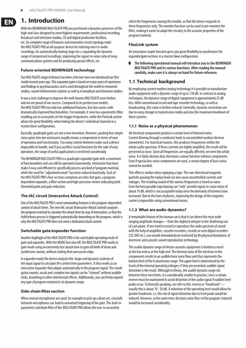
8122019 XR4400_P0050_M_ENpdf
httpslidepdfcomreaderfullxr4400p0050menpdf 614
6 MULTIGATE PRO XR4400 User Manual
2 The Design Concept
21 High quality components and design
The philosophy behind BEHRINGER products guarantees a no-compromise circuitdesign and employs the best choice of components The operational amplifiersNJM4580 which are used in the MULTIGATE PRO are exceptional They boastextreme linearity and very low distortion characteristics To complement thisdesign the choice of components includes high tolerance resistors and capacitors
detent potentiometers and several other stringently selected elements
For the first time the MULTIGATE PRO XR4400 uses SMD technology(Surface Mounted Device) These sub-miniature components known fromaerospace technology allow for an extreme packing density plus the unitrsquosreliability could be improved Additionally the unit is manufactured incompliance with a ISO9000 certified management system
22 Inputs and outputs
221 Balanced inputs and outputs
As standard the BEHRINGER MULTIGATE PRO is installed with electronicallyservo-balanced inputs and outputs The new circuit design features automatic
hum and noise reduction for balanced signals and thus allows for trouble-freeoperation even at high operating levels Externally induced mains hum etcwill be effectively suppressed The automatic servo-function recognizes thepresence of unbalanced connectors and adjusts the nominal level internally toavoid level differences between the input and output signals (correction 6 dB)
3 InstallationYour BEHRINGER MULTIGATE PRO was caref ully packed in the fac tory andthe packaging was designed to protect the unit from rough handlingNevertheless we recommend that you carefully examine the packaging and itscontents for any signs of physical damage which may have occurred in transit
loz If the unit is damaged please do not return it to us but notify yourdealer and the shipping company immediately otherwise claims fordamage or replacement may not be granted Shipping claims must bemade by the consignee
Please take the time to complete and return the warranty card within 14 days ofthe date of purchase otherwise you will lose the right to the extended warrantyOr just use our online-registration (behringercom)
31 Rack mountingThe BEHRINGER MULTIGATE PRO fits into one standard 19 rack unit of space(1 frac34) Please allow at least an additional 4 depth for the connec tors on theback panel Be sure that there is enough air space around the unit for coolingand please do not place the MULTIGATE PRO on high temperature devices such aspower amplifiers etc to avoid overheating
32 Mains voltage
Before you connect your MULTIGATE PRO to the mains please makesure that your local voltage matches the voltage required by theunit The fuse holder on the female mains connector has 3 triangularmarkers with two of these triangles opposing each other Your MULTIGATE
RPO is set to the operating voltage printed next to these markersand can be set to another voltage by turning the fuse holder by 180degCAUTION this instruction does not apply to export models exclusivelydesigned eg for 115 V operation
33 Audio connections
The audio inputs and outputs on the BEHRINGER MULTIGATE PRO arefully balanced If possible connect the unit to other devices in a balancedconfiguration to allow for maximum interference immunity
loz Please ensure that only qualified persons install and operate theMULTIGATE PRO During installation and operation the user must havesufficient electrical contact to earth Electrostatic charges might affect
the operation of the MULTIGATE PRO
1 2
3
2 1
3
Pin 1
Output Cable Input
Pin 2 = (+) Signal Positive
Pin 3 = (-) Signal
Shield
(+) Signal + Hum
(-) Signal + Hum
Negative
(+)Hum + Signal
(-)Hum + Signal
2 x Signal
Ground
RFI and Hum
= Signal + 6 dB
Fig 31 Compensation of interference with balanced connections
8122019 XR4400_P0050_M_ENpdf
httpslidepdfcomreaderfullxr4400p0050menpdf 714
7 MULTIGATE PRO XR4400 User Manual
output
For unbalanced use pin 1 and pin 3have to be bridged
1 = groundshield2 = hot (+ve)3 = cold (-ve)
input
12
3
1 2
3
Balanced use with XLR connectors
Fig 32 Different plug types
loz Never use unbalanced XLR connections with microphone cables as thiswould short-circuit any phantom power transmitted over these cables
4 ControlsThe BEHRINGER MULTIGATE PRO has four channels Each of these channels isequipped with 3 or 4 push-buttons 6 rotary controls and 11 LEDs
41 The front panel control elements
(6)(4) (12)(11)
(1) (2) (3) (5) (7) (8) (9) (10)
Fig 42 Control elements on the front panel
(1) The FREQUENCY control determines the lower limit frequency of thesidechain filter and covers a range from 100 Hz to 10 kHz
(2) The BANDWIDTH control determines the slope or bandwidth of thesidechain filter The bandwidth can be set within a range from 23 to07 octaves so as to realize even extremely narrow-band filter settings
(3) The FILTER control activates the parametric sidechain filter To edit this filterthere you can use the frequency and BW control
(4) The MONITOR switch establishes a link between the sidechain control signaland the audio output As it also mutes the audio input signal the user canpre-monitor the parametric filter output which makes it easier to tune thefilter by ear
loz Please note that the MONITOR switch disables the channelrsquos audio signal
(5) Use the THRESHOLD control to set the threshold point of the expandergate function within a range from BYPASS to +10 dBu Signals below thethreshold are reduced in level When the signal drops below the thresholdthe holdrelease function starts reducing the signal to a level adjustable
with the RANGERATIO control
loz Please note that the MULTIGATE PRO enters bypass mode when theTHRESHOLD control is set to its left stop position ie all processingfunctions are disabled and the signal is routed directly from the inputto the output
(6) This ldquotraffic lightrdquo LED chain shows the current operating mode of the unitthe ldquo+rdquo LED (red) indicates that the sidechain signal is below the thresholdthe HOLD LED (yellow) informs you that the hold circuitrelease process hasbeen activated while the ldquo-rdquo LED (green) shows that the sidechain signal isabove the threshold
(7) The HOLD control determines the delay applied to the starting point of
the release process after the signal has dropped below the thresholdThe setting range is 0 to 4 seconds
strain relief clamp
sleeve
tip
sleeve(groundshield)
Unbalanced frac14 TS connector
tip(signal)
strain relief clamp
sleeve
ring
tip
sleevegroundshield
For connection of balanced and unbalanced plugsring and sleeve have to be bridged at the stereo plug
Balanced frac14 TRS connector
ringcold (-ve)
tiphot (+ve)
Fig 41 MULTIGATE PRO front panel
8122019 XR4400_P0050_M_ENpdf
httpslidepdfcomreaderfullxr4400p0050menpdf 814
8 MULTIGATE PRO XR4400 User Manual
loz The HOLD control is enabled in GATE mode only
(8) The RELEASE control determines the time of the release processThis process begins after the end of the hold phase and ends when the gainreduction adjusted with the RANGE control is achieved The setting range ofthe RELEASE control is from 005 to 4 seconds
loz The RELEASE control is enabled in GATE mode only
(9) The MODE switch is used to set the operating mode of the respective
channel When the switch is out the corresponding section works as anultra-fast gate In this mode even percussive signals can be processedwithout any signal loss With the MODE function on the IRC expander(Interactive Ratio Control) is activated This interactive control functionallows for the program-dependent expansion of complex signals Both theattack time and the fade-out characteristics (ratio) vary depending on theprogram material The agreeable results of this automatic process are lesscritical adjustment work and ldquoinaudiblerdquo expansion of the program material
(10) The RANGERATIO control performs a dual function depending on theposition of the MODE switch (ie depending on the operating mode of theunit gate or expander) the RANGERATIO control determines the maximumamount of gain reduction or the expansion curve In gate mode this controladjusts the RANGE determining the amount of maximum gain reductionfrom 0 dB to -80 dB In expander mode it works as a RATIO control settingthe expansion ratio The ratio function determines the input vs output levelratio for all signals below the threshold The setting range is from 11 to 14
(11) The 8-digit GAIN REDUCTION meter informs you about the current amountof gain reduction within a range from 1 to 40 dB
(12) When you press the COUPLE switch this channel is automatically configuredas a ldquoslaverdquo channel Its left neighbor becomes the ldquomasterrdquo now controllingboth channels in all their parameters
42 The rear panel elements
BEHRINGER
MULTIGATE PRO
MODEL XR4400
CONCEIVED AND DESIGNED BY
BEHRINGER GERMANY
MADE IN CHINA
ALL INP UTS amp OUT PUTS
FULLY BALANCED
TIP PIN 2
RING PIN 3
SLEEVE PIN 1
ALL INP UTS amp OUTP UTS
FULLY BALANCED
TIP PIN 2
RING PIN 3
SLEEVE PIN 1
ALL INPU TS amp OUTP UTS
FULLY BALANCED
TIP PIN 2
RING PIN 3
SLEEVE PIN 1
ALL INP UTS amp OUTP UTS
FULLY BALANCED
TIP PIN 2
RING PIN 3
SLEEVE PIN 1
INPUTS 4OUTPUTS 4 0UTPUTS 3 INPUTS 3 0UTPUTS 2 INPUTS 2 0UTPUTS 1 INPUTS 1
(14)
(13)
(16) (15)
Fig 43 Rear panel elements
(13) FUSE HOLDER VOLTAGE SELECTOR Please make sure that your localvoltage matches the voltage indicated on the unit before you at tempt toconnect and operate the MULTIGATE PRO Blown fuses may only be replacedby fuses of the same type and rating
(14) MAINS CONNECTION Use the enclosed power cord to connect theunit to the mains Please also note the instructions given in theldquoInstallationldquo chapter
(15) AUDIO IN These are the audio inputs of your MULTIGATE PRO available bothas balanced 63 mm jack and XLR connectors
(16) AUDIO OUT These are the audio outputs of your MULTIGATE PROMatching phone jack and XLR connectors are wired in parallel
5 Technical Background51 EXPANDER mode
As already described a so-called downward expander automatically reducesthe overall level of all signals that drop below an adjustable threshold and thusexpands the dynamic range of the program material In other words an expanderis the opposite of a compressor Expanders usually work with a relatively flat ratiocurve to fade out the signal smoothly
Noise gates are a special form of expander using a much steeper ratio curve toabruptly cut the signal when it drops below the threshold As expanders andgates are quite similar in what they do the following description of expandersand their functionalities also applies to noise gates
amplitude
min
max input
audio signal
masked noise audible noise
time
amplitude
min
maxoutput
audio signal
masked noise audible noise
threshold
time
0
0
Fig 61 Expander mode
52 Interactive control functions
Like the COMPOSER INTELLIGATE MULTICOM and others the MULTIGATE PROuses the newly developed INTERACTIVE principle based on a chain of intelligentcontrol functions For example the IRC expander (Interactive Ratio Control)does not use a fixed ratio curve but varies this curve depending on the input leveland the setting of the THRESHOLD control
8122019 XR4400_P0050_M_ENpdf
httpslidepdfcomreaderfullxr4400p0050menpdf 914
9 MULTIGATE PRO XR4400 User Manual
The following chapter describes the interactive control functions in full detail
521 THRESHOLD control
The THRESHOLD control determines the threshold point and disables therespective channel As it covers a very wide setting range it can be easily adaptedto any operating level
Input levels above the adjusted threshold point pass the circuit unprocessedHowever as soon as the input signal drops below the threshold dynamicsprocessing sets on Simple noise gates usually have a control to set the switch-onand switch-off thresholds but must perform their task without any dedicatedcontrol elements that allow for varying the envelopes
The BEHRINGER MULTIGATE PRO however is equipped with all necessary controloptions The following section makes clear why it is so important to be able toadjust these parameters
522 Attack release and hold times
The BEHRINGER MULTIGATE PRO is equipped with a MODE switch as well as aHOLD and RELEASE control to adjust the time-domain parameters that determinethe so-called envelope
amplitude
attack hold release
time
max
0
Fig 62 Principle of envelope function
Attack time
The quality of an expandergate is largely determined by the speed of its attackfunction (rise time) This parameter defines the time the expander needs afterthe signal has passed the threshold to recover from the applied gain reductionie to reverse the control process
Extremely short transients (level peaks) such as hand claps and percussiveinstruments etc require an extremely short attack time to prevent the expander
from cutting the signal flanks and thus deteriorating the sound
The new BEHRINGER-developed UTR circuit (Ultra Transient Response)in combination with a high-grade VCA allows for an extremely short responsetime in gate mode without audible switching noise as it is generated by manyconventional designs
Release time
Another important parameter is the release time as it determines the time thegate needs to reduce the signal level by a certain amount after the signal hasdropped below the threshold
Hold time
The hold-time parameter enables you to delay the star ting point of the releaseprocess In particular when processing frequently interrupted signals such asvocals an additional hold-time parameter is indispensable to prevent the gatefrom switching off and back on during signal pauses
523 IAC circuit (Interactive Attack Control)
The MULTIGATE PRO features an IAC circuit (Interactive Attack Control)which analyzes the program material to calculate the attack time by way ofinteraction so that the holdrelease process is triggered automatically dependingon the program material This is the reason why the MULTIGATE PRO does notneed a dedicated attack control
524 RANGE function
On the MULTIGATE PRO the dynamic processing is controlled by a high- gradeVCA with a working range of more than 100 dB ie the input signal can bereduced in level by as much as 100 dB
For most applications however it is neither desirable nor necessary to cutthe signal completely after it has dropped below the threshold In par ticularwhen processing signals with lots of background noise this would result inabrupt and audible control processes that are less likely to enhance the overallsound quality
For this reason the MULTIGATE PRO is equipped with a RANGE control thatallows you to limit the maximum gain reduction applied Thus you can usesmaller amounts of gain reduction making it possible to retain the natural soundof the program materialmdashin particular with signals that contain plenty ofinterference noise
525 IRC circuit (Interactive Ratio Control)
In conventional expanders the control processes cut the signal abruptly belowthe threshold which usually leads to less satisfying results because the onsetof the control function becomes audible When inaudible expansion is neededit is therefore better to use a ldquosoft-kneerdquo characteristic around the thresholdpoint that allows for a smoother transition
The BEHRINGER MULTIGATE PRO uses the newly developed IRC expander(Interactive Ratio Control) whose attack time and ratio characteristics varyautomatically depending on the program material
The IRC expander is switched on with the MODE switch Low ratios and hence
subtle expansion produce a ldquosmoothrdquo transition while higher ratios and heavyexpansion result in a ldquosteeperrdquo transition between the characteristic curves
This so-called interactive ie nonlinear IRC characteristic is perfectly adaptedto human hearing critical wanted signals around the threshold point are lessexpanded while interference signals with lower levels (eg background noise)are processed and faded out with a higher expansion ratio
8122019 XR4400_P0050_M_ENpdf
httpslidepdfcomreaderfullxr4400p0050menpdf 1014
10 MULTIGATE PRO XR4400 User Manual
output
input
gain 0 dB
IRC curve
expander 18
noise gate 1infin
threshold
Fig 63 IRC characteristic curve
The result is an expansion process that is less difficult to adjust and more toleranttowards wanted signals whose levels are only slightly above the level of thebackground noise
526 RATIO function
The ratio of the input-level-change vs output-level-change after the onset of thecontrol process ie after the signal has dropped below the threshold is calledexpansion ratio and can be set with the RATIO control RATIO settings from 112through 14 give you smooth and exactly dosed downward expansion
The RATIO scale printed on the front panel indicates the expansion ratio indecibels ie it shows you the decibels by which the output signal is cut for eachreduction by one dB of the input signal
With a 11 ratio the output signal level is the same as the input signal levelie there is no signal change A ratio of 12 means that the output signal isreduced by 2 dB when the input signal drops below the threshold by 1 dB
Accordingly with a ratio of 14 the output signal is cut in level by 4 dB when theinput signal is 1 dB below the threshold
53 FLEXLINK function
The four channels of the MULTIGATE PRO can be operated both independentlyof each other and in couple mode In particular when you record a choir it willbe useful to couple the individual microphone channels For example when allmicrophones are controlled by one singer all vocals start and stop preciselyat the same point of time Also when synchronizing several instrumentsinaccurate entries of individual musicians can be avoided
To expand phase-coherent stereo signals (ie signals having the same phase)it is imperative that the control processes be triggered simultaneously in both
channels Due to the differences in perceived loudness between the left and rightchannels unwanted shifts with reference to the stereo basis would be produced
The innovative FlexLink function implemented in the MULTIGATE PRO allows fora variety of couple options For example when you press the COUPLE switch ofchannel 3 this channel is automatically configured as a ldquoslaverdquo channel while itsneighbormdashchannel 2mdashbecomes the ldquomasterrdquo now controlling both channels inall their parameters
Activating the COUPLE switch automatically disables all controls and switchesof channel 3 (except for the MONITOR switch) Now the controls of channel 2take over full control of channel 3 Similar to a stereo f ader both channels workin sync To control channels 2 and 3 from channel 1 simply press the COUPLEswitches of channel 2 and 3
54 The SIDECHAIN filter
Each channel has a parametric filter whose frequency and quality (bandwidth)can be set precisely This tunable filter allows you to select and fade outspecific frequencies that would otherwise lead to unwanted triggering of theexpander circuit
541 The MONITOR function
This switch links the sidechain control signal with the audio output while mutingthe audio input signal so that you can pre-monitor the filter output and tune theparametric filter
loz Please note that the channelrsquos entire processing functions will bedisabled when you press the MONITOR switch
6 ApplicationsThis chapter describes a few typical applications of the BEHRINGER MULTIGATEPRO Starting from the basic setting shown below you can find solutions tomost dynamics-based problems Please take your time to study the followingapplication examples thoroughly so as to be able to fully exploit the variety offeatures your MULTIGATE PRO offers
Basically the BEHRINGER MULTIGATE PRO can be used in three areasof application
1 Eliminating interference noise and suppressing crosstalk in multi-channel ormulti-microphone configurations
2 Expanding the dynamic range of compressed program materialrefreshing sampled sounds and creating special effects and sounds
3 Using the MULTIGATE PRO as a de-esser and to specifically eliminateinterference noise from recordings as well as to reduce the risk of feedbackin live situations
61 Basic setting
Understandably there is no standard setting that suits all kinds of applicationsRather the controls and switches must be set specifically for the applicationon hand However by studying the following practice-oriented descriptionsof typical applications you will soon develop a feel for how the variousfunctions work
611 The gate function
ldquoGatingrdquo is a so-called ldquohigh ratiordquo expander function and represents thesimplest function of the BEHRINGER MULTIGATE PRO When the expander isoperated with maximum gain reduction (RANGE control fully to the left) it worksin ldquohard gatingrdquo mode The gate function is used to automatically mute singlechannels in multitrack mixdowns stage microphones currently not in use and to
suppress background noise and crosstalk in multi-track recordings In particularwhen processing percussive instrument the use of the ldquohard gatingrdquo functionis recommended
A few examples show you how to do it
Electric signals from percussion instruments have a very short rise time The timebetween single hits on the instruments is normally filled up with noise producedby adjacent instruments or room reverb which makes it difficult or evenimpossible to separate microphones acoustically This unwanted crosstalk effectcan be accurately eliminated with the MULTIGATE PRO
8122019 XR4400_P0050_M_ENpdf
httpslidepdfcomreaderfullxr4400p0050menpdf 1114
11 MULTIGATE PRO XR4400 User Manual
Adjust all controls and switches to the following basic settings
Control elements Position
MONITOR switch OUT
SC FILTER switch OUT
THRESHOLD switch fully clockwise
HOLD control center position
RELEASE control center position
MODE switch GATE
RANGERATIO control fully counter-clockwise
Tab 61 Initial settings of the MULTIGATE PRO
THRESHOLD control
Now turn the THRESHOLD control counter-clockwise until the lowest signaldelivered by the instrument you wish to record triggers the expander and isreproduced without any sound deterioration The ldquo+rdquo LED lights up as soon asthe expander is triggered When everythingrsquos set up properly you will hear theinstrument clearly ldquostand outrdquo against the overall sound image
HOLD control (available in GATE mode only)
The program material (eg speechvocal recordings) often contains many andsometimes very short signal pauses which could switch the gate off and back onover and again The hold function prevents this annoying ldquoflutterrdquo effect knownfrom conventional designs simply by delaying the starting point of the releaseprocess Thus the gate remains on during short signal pauses When the adjustedhold time has expired the gate closes the audio channel depending on how therelease function has been set
loz Please note that this control can be used in gate mode only
RELEASE control (available in GATE mode only)
Many percussion instruments have long decay times (eg cymbals) As the releasetime can be adjusted on the MULTIGATE PRO the device allows you to follow the
decay curve of the instrument so that its overall sound character will be retainedIn this way you can avoid that short release times affect the natural decay phaseof the instrument or its corresponding reverb ambiance
Slowly decaying or heavily reverberated signals are best processed with longrelease times You will note that with most drum sounds a short release timeshould be used for the sake of acoustic separation while longer release times areusually better for cymbals and tom-toms
Once all control elements have been set properly your percussion sounds will beldquodryrdquo ldquopowerfulrdquo and acoustically well-defined
loz Please note that this control can be used in gate mode only
RANGE controlThe RANGE control determines the amount of maximum attenuation of theaudio signal When you process instruments with long decay times it willbe helpful to set the RANGE control to mid-travel position so that the signalwill not be suppressed completely Although the MULTIGATE PRO allows for amaximum gain reduction of 80 dB it is usually not useful to reduce the signallevel by this maximum amount In particular with highly noise-affected signalswe recommend that you use a signal attenuation of not more than 10 to 20 dBso that the onset of the gate function will not become too obvious
612 The expander function
In contrast to the gate function the expander triggers a continuous attenuationof the signal as soon as it has dropped below the threshold
RATIO control
With the MODE switch in the MULTIGATE PRO works as an interactive expanderThe RATIO control determines the expansion curve For example when a pieceof music was highly compressed during the recording session the lost dynamicscan be restored through complementary expansion With a bit of feeling youcan set the following controls by ear so that the original dynamics (prior to thecompression process) will be restored
We recommend that you set the RATIO control to about 112 through 12 to allowfor a ldquosmoothrdquo expansion curve and that you adjust the THRESHOLD control sothat the entire dynamic range of the music piece will be below the thresholdpoint Now set the THRESHOLD control so that only the loudest passages of theprogram material surpass the threshold point (ldquo-rdquo LED flashes) In the same wayyou can artificially expand the dynamic range of any instrument In particularwhen processing sampled sounds expansion can produce nice resultsbecause samplers usually have a highly limited dynamic range When processingpercussion sounds (eg snare drum) you can use downward expansion to create
interesting effects for example by setting the threshold to about mid-positionso that only the ldquolowerrdquo part of the dynamics will be processed the signal decaysunchanged until the adjusted threshold i s reached and any subsequent signalportions are faded out with increasing attenuation
62 Proper positioning of microphones
The main task of an expander is to separate unwanted background noise from theactual signal and to eliminate this noise ldquoinaudiblyrdquo Understandably there mustbe a minimum difference in the levels of wanted signal and interference signalso as to be able to define a threshold point for the expander
However the optimum operation of an expander depends on the proper choiceand positioning of the microphones
Be extremely careful when instruments with high-frequency portions are playedto the sides or back of a microphone with a cardioid polar pattern Most roommicrophones suffer from a deterioration of their directivity when picking uphigh frequencies For example with a sensitivity difference of not more than2-3 dB around 5-10 kHz between the main and lateral axes cymbals can produceenormous crosstalk in tom-tom microphones or the hi-hats can mask the soundof the snare drum
You should make optimum use of the specific directivity of a microphone toacoustically separate other instruments as perfectly as possible Do as best asyou can to separate the sound sources acoustically simply by positioning themicrophones correctly
Yet in some applications even perfectly positioned microphones might
not produce satisfying results With its side-chain function the BEHRINGERMULTIGATE PRO gives you the option of frequency-selective expansion and thusanother aid to ensure perfect acoustic separation of the sound sources
8122019 XR4400_P0050_M_ENpdf
httpslidepdfcomreaderfullxr4400p0050menpdf 1214
12 MULTIGATE PRO XR4400 User Manual
63 Applications
631 Suppressing crosstalk in multi-track applications
One of the most frequent applications of an expandergate is the eliminationof unwanted crosstalk between single channels during recording or playbackIn particular when recording acoustic drum sounds this type of application isfrequently used because here several microphones closely positioned next toeach other are used
The high sound pressure levels of the individual instruments lead to crosstalkin adjacent microphones Frequency cancellations and a non-defined sound(ldquocomb filterrdquo effect) are the result It has proven wise to use a separatemicrophone for each drum instrument and to ldquogaterdquo each microphone channel
Insert the BEHRINGER MULTIGATE PRO into the recording channel of the snaredrum for example and adjust the device so that it responds only to hits on thesnare drum Each single microphone should be optimally positioned beforeand the threshold of the respective channel should be set so that the drum soundcan be separated cleanly just as if the instrument were played alone
632 Reducing crosstalk in stage microphones
The MULTIGATE PRO can be used in a variet y of livestage and multimicrophoneapplications a moderately set expander can effectively suppress backgroundnoise or the noise build-up that is typically produced by compressors as wellas crosstalk between microphones etc without causing other unwantedside effects
Typically an expander can be used to process vocal tracks Particularly whenusing a compressor the distance between singer and microphone is of crucialimportance As the distance increases more and more disturbing backgroundnoise is picked up You should therefore use the expander function to fade outunwanted interference noise ldquoinaudiblyrdquo during signal pauses
In live situations you can eliminate bleeding for instance from drum to pianotracks or clean your recordings from other acoustic ldquopollutionrdquo
If you do not have enough microphones (or MULTIGATE PRO) to record eachinstrument separately try forming so-called subgroups comprise the snare andmiddle toms side toms kick drum and cymbals in one group using the subgroupfacilities on your mixing console
The goal is to position the grouprsquos microphones and to adjust the expanderso that with each hit on a specific instrument only one microphone opensthus transmitting only one specific instrument while the remaining microphonesremain muted
633 Reducing feedback in stage microphones
As soon as a singer sings into hisher microphone background noise is maskedand thus not perceived During signal pauses however the microphone picks
up the noise from PA and monitor speakers which can lead to torturing feedbackBy inserting the MULTIGATE PRO into the vocal channel and by adjusting it tomute the microphone when it is not in use you can reduce the risk of feedback inthis particular channel
Basically this configuration should be used for all stage microphones
7 Specifications
Audio Input
Connectors XLR and frac14 jack
Type RF filtered servo-balanced input
Impedance 50 kOhm balanced 25 kOhm unbalanced
Max Input Level +21 dBu balanced and unbalanced
CMRR typ 40 dB gt55 dB 1 kHz
Audio Output
Connectors XLR and frac14 jack
Type Electronically servo-balanced output stage
Impedance 60 Ohms balanced 30 Ohm unbalanced
Max Output Level +21 dBu +20 dBm balanced andunbalanced
System Specifications
Frequency Response 18 Hz to 30 kHz +- 3 dB
Noise gt95 dBu unweighted 22 Hz to 22 kHz
THD 0008 typ +4 dBu 1 kHz Gain 1
IMD 001 typ SMPTE
Crosstalk lt-100 dB 22 Hz to 22 kHz
Gate Section
Type UTR (Ultra Transient Response) gate
Threshold variable (BYPASS to +10 dBu)
Attack program dependent
Hold variable (0 to 4 sec)
Release variable (50 ms to 4 sec)
Range variable (0 to -80 dB)
Expander Section
Type IRC (Interactive Ratio Control) expander
Attack program dependent
Ratio variable (11 to 14)
Side-Chain Filter
Frequency variable (100 Hz to 10 kHz)
BW (Bandwidth) variable (23 to 07 oct)
8122019 XR4400_P0050_M_ENpdf
httpslidepdfcomreaderfullxr4400p0050menpdf 1314
13 MULTIGATE PRO XR4400 User Manual
Function Switches
Monitor monitors the side-chain key signal
Filter activates the side-chain filter
Mode gateexpander switch
Couple activates the FlexLink function
Indicators
ldquo+rdquo indicator signal is below threshold
ldquoHoldrdquo indicator signal reaches the threshold
ldquo-rdquo indicator signal is above threshold
Gain Reduction 8-segment LED display1361015203040 dB
LED indicator for each function switch
Power Supply
Mains Voltages
USACanada 120 V~ 60 Hz
UKAustralia 240 V~ 50 Hz
Europe 230 V~ 50 Hz
General Export Model 100 - 120 V~ 200 - 240 V~ 50 - 60 Hz
Power Consumption max 20 Watts
Fuse 100 - 120 V~ T 630 mA H200 - 240 V~ T 315 mA H
Mains Connection Standard IEC receptacle
Physical
Dimension 445 x 483 x 217 mm (1 frac34 x 19 x 8 frac12)
Net Weight approx 22 kg (approx 48 lbs)
Shipping Weight approx 35 kg (approx 77 lbs)
BEHRINGER is constantly striving to maintain the highest professional standards As a result of these ef forts
modifications may be made from time to time to existing products without prior notice Specifications and
appearance may differ from those listed or shown
8122019 XR4400_P0050_M_ENpdf
httpslidepdfcomreaderfullxr4400p0050menpdf 1414
We Hear You
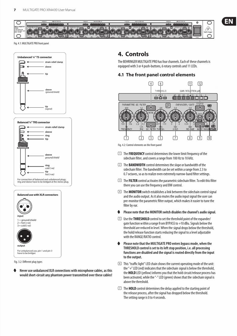
8122019 XR4400_P0050_M_ENpdf
httpslidepdfcomreaderfullxr4400p0050menpdf 1414
We Hear You