xs850g owner’s manual 1st printing, july 1979 all …
TRANSCRIPT


XS850G OWNER’S MANUAL1ST PRINTING, JULY 1979ALL RIGHTS RESERVED,
BY YAMAHA MOTOR COMPANYLIMITED, JAPAN
PRINTED IN JAPANP/N LIT-l 1626-01-79
PLEASE READ THIS MANUAL CAREFULLY AND COMPLETELYBEFORE OPERATING THIS MOTORCYCLE.DO NOT ATTEMPT TO OPERATE THIS MOTORCYCLE UNTILYOU HAVE ATTAINED A SATISFACTORY KNOWLEDGE OF ITSCONTROLS AND OPERATING FEATURES AND HAVE BEENTRAINED IN SAFE AND PROPER RIDING TECHNIQUES.
REGULAR INSPECTIONS AND CAREFUL MAINTENANCE AREREQUIRED IN ADDITION TO RIDING SKILL IN ORDER TOENJOY THE CAPABILITIES AND RELIABILITY OF THIS MOTOR-CYCLE SAFELY.
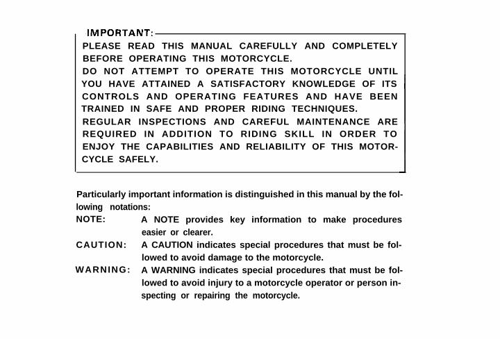
Particularly important information is distinguished in this manual by the fol-lowing notations:NOTE:
CAUTION:
WARNING:
A NOTE provides key information to make procedureseasier or clearer.A CAUTION indicates special procedures that must be fol-lowed to avoid damage to the motorcycle.A WARNING indicates special procedures that must be fol-lowed to avoid injury to a motorcycle operator or person in-specting or repairing the motorcycle.

NOTE:This manual should be considered a permanent part of this motorcycle andshould remain with it even if the motorcycle is subsequently sold.
-SAFETY WARNINGS:1, Traffic regulations vary from state to state. Study the regulations
in your state before riding this motorcycle.2. This motorcycle is designed for on-road use only. It is not suita-
ble for off-road use.3. GASOLINE IS HIGHLY FLAMMABLE:* Always turn off the engine when refuelling.* Take care not to spill any gasoline on the engine or exhaust
pipe(s)/muffler(s) when refuelling.* Never refuel while smoking or in the vicinity of an open flame.
4. If you should swallow some gasoline, or inhale a lot of gasolinevapor, or allow some gasoline to get in your eye(s), see yourdoctor immediately. If any gasoline spills on your skin or cloth-
ing, immediately wash it with soap and water and change your
clothes.

5.
*
*
6.
7.
6.
Always turn off the engine before leaving the motorcycle unat-tended and do not forget to remove the ignition key. When park-ing the motorcycle, note the following:The engine and exhaust pipe(s)/muffler(s) may be hot. Park themotorcycle in a place where pedestrians or children are not like-ly to touch the motorcycle.Do not park the motorcycle on a slope or soft ground; the motor-cycle may overturn.When transporting the motorcycle in another vehicle, be sure itis kept upright and that the fuel petcock(s) is turned to the “ON”or “RES” position (for vacuum type)/“OFF” position (for manualtype). If it should lean over, gasoline may leak out of the car-
bretor or fuel tank.Never start your engine or let it run for any length of time in aclosed area. The exhaust fumes are poisonous and may causeloss of consciousness and death within a short time. Alwaysoperate your motorcycle in en area with adequate ventilation.
Always wear a helmet, gloves, trousers (tapered around the cuffand ankle so they do not flap), and a brightly colored jacket.

INTRODUCTION
Congratulations on your purchase of theYamaha XS850G. This model represents theproduct of many years of Yamaha experiencein the production of fine sporting. touring,and pacesetting racing machines. You cannow appreciate the high degree of crafts-manship and reliability that have madeYamaha a leader in these fields.This manual will provide the owner with agood basic understanding of the operationand basic maintenance of this vehicle. If you
have any questions regarding the operationor maintenance of your motorcycle. pleaseconsult your Yamaha dealer.
- N O T I C E :Some data in this manual may becomeoutdated due to improvements made tothis model in the future. If there is anyquestion concerning this manual, con-sult your nearby Yamaha dealer.
This Yamaha Motorcycle in its design andmanufacture fully complies with the emis-sions standards for clean air applicable atthe date of manufacture. Yamaha has metthese standards without reducing themotorcycle’s performance or economy ofoperation. To maintain these high standards.it is important that you and your dealer payclose attention to the recommendedmaintenance schedules and operating in-structions contained within this manual.
SERVICE DEPT.INTERNATIONAL DIVISIONYAMAHA MOTOR CO., LTD.

CONTENTSLOCATION OF THE “CAUTION ANDSPECIFICATION LABELS” ,.,.,....................... 1DESCRIPTION ..,,,...........................................~ 2MACHINE I D E N T I F I C A T I O N 3CONTROL F U N C T I O N S 4PRE-OPERATION CHECKS ..,,...................... 15OPERATION AND IMPORTANTRIDING POINTS 24PERIODIC MAINTENANCE ANDMINOR REPAIR .,.......,,,,,,.,..,.,.,...................... 30CLEANING AND STORAGE .,....................... 72MISCELLANEOUS 75SPECIFICATIONS 77WARRANTY INFORMATION 80MAINTENANCE RECORD 81WIRING DIAGRAM 83


RIGHT SIDEDESCRIPTION
INSTRUMENTS
LEFT SIDE

MACHINEIDENTIFICATION
Frame serial numberThe frame serial number is stamped into theright side of the steering head pipe.
Engine serial numberThe engine serial number is stamped into theelevated part of the right rear section of theengine.
NOTE:The first three digits of these numbers are formodel identification; the remaining digits arethe unit production number. These identifica-tion numbers are used to register Yourmotorcycle with the licensing authority inyour state as well as with the manufacturer.Keep a record of these numbers for referencewhen ordering parts from Your Yamaha deal-er. In case of theft, the authorities will needthese numbers and Your model name foridentification.

ON:
RES:
With the lever in this position fuelflows if the engine is running but stopsif the engine is not running.This indicates “RESERVE”. If you runout of fuel while riding, move the leverto “PRI” and switch to “RES” posi-tion after starting the engine. Then, fillthe tank at the first opportunity.
NOTE:In the “ON” and “RES” positions the petcockworks on pressure from the engine turningover. If the line connecting the petcock to thecarburetor intake manifold is not connectedor has a leak the petcock will not functionproperly.
PRI: This indicates “PRIME”. With the fuelpetcock in this position fuel flowswhether the engine is running or not. Ifthe fuel tank is completely empty, refillthe tank, prime the carburetor in this
position, and then switch to the “ON”position after starting the engine.
Starter (CHOKE)When cold, the engine requires a richer fuelmixture for starting. A separate starter circuit,which is controlled by the starter, suppliesthis mixture.The starter on this model is a 2-position typeas follows:
1. Pull the starter fully up.-When starting a cold engine.
2. Push back the starter half-way.-When warming up the engine.
NOTE:Refer to “Starting and warming up a coldengine” for proper operation.

Steering lockTo lock the steering, turn the handlebars fullyto the right, insert the key into the steeringlock and turn the key about l/8 turn coun-terclockwise. Then push the key in and turn itabout l/8 turn clockwise. After checking ifthe lock is engaged, remove the key from thelock. To release the lock. reverse the abovesteps.
Seat lockTo open the seat lock insert the key in thelock and turn it counterclockwise and pull thelever backwards.

In reinstalling the seat. insert the lobes onthe seat front into the receptacles on theframe, then push down the seat at the end.After making sure the seat is securely fitted,turn the key clockwise to the center positionto lock.
Helmet holderTo open the helmet holder. insert the key inthe lock and turn it clockwise.To lock the helmet holder, replace the holderin the original position.
Never ride with a helmet in the helmetholder. It could interfere with rear wheel
movement, causing loss of control andpossibly an accident.
Side cover (Left and Right)To remove the right side cover, pull out the
bottom of the cover. To reinstall the cover.make sure the top of the cover is securely
seated on the hinge hooks, then push thebottom of the cover into its snap fitting.
-12-

Front forks
The front forks of this model are pneumome-chanical; namely, a combination air and me-chanical coil spring in the inner tube providessuspension best suited to the motorcycle’sload (ex: optional accessories etc.) and ridingconditions by the adjustment of the air pres-sure. Refer to page 54 for proper adjustmentprocedures.
Always adjust the fork preload to thesame position on each side. Uneven ad-
::::::b::justment can cause poor handling and
Rear shock absorberThe spring preload and the damping forcecan be adjusted to suit motorcycle load (ex:optional accessories etc.) and riding condi-tions. Refer to page 54 for proper adjustmentprocedures.
-I3-

An optional heavy duty rear shock absor-ber spring is available for this model.
Please ask your nearby Yamaha dealer forfurther details.
Kick starterTo start the engine. rotate the kick crank.push down lightly with foot until gearsengage, and then kick forcefully. This modelcannot be started unless the transmission isin neutral.
* Heavy duty rear shock absorberspring: P/No. 3J2-22212-A0
i

PRE-OPERATION CHECKS (DAILY)
Before using this motorcycle check the following points:
No. Item Routine Page
Check operation, free play and fluid.1. Brakes (Front and Rear) Top-up with DOT. #3 brake fluid 1 6 . 4 4
if necessary.
2. Clutch
3. Engine oil
4 Middle/final Gear Oil
5. Throttle
6 . Bat tery
7. Lights/Signals
8. Wheels/Tires
9. Fittings/Fasteners
Check operation. condition and free play.Adjust if necessary.
Check engine oil level. add oil if necessary.
Check for leakage visually.
Check for smooth operation.Adjust if necessary.
Check fluid level. top-up withdistilled water if necessary.
Check operation.
Check tire pressure. wear damage.
Check all chassis fittings and fasteners.Adjust. if necessary.
1 7 . 4 9
1 7 . 3 8
1 8 . 4 0
1 7 . 5 0
2 3 . 5 8
2 2
18
37
-15-

Pre-operation checks should be made each time the motorcycle is used. Such an inspectioncan be accomplished in a very short time, and the added safety it assures is more than worththe time involved.
. . . . .._.._ -.
1. The engine, exhaust pipe(s), and muffler(s) will be vary hot after the engine has
been run. Be careful not to touch them or to allow any clothing item to contactthem during inspection or repair.
2. If any item in the PRE-OPERATION CHECK is not working properly, have it in-spected and repaired before operating the motorcycle.
Brakes (See page 44 for more detail)1. Brake lever and brake pedal
Check for correct play in the front brake
lever and rear brake pedal. Make surethey are working properly. Check the
brakes at low speed shortly after start-ing out.
-16-
- W A R N I N G :
A soft, spongy feeling in the brake lever
(and/or brake pedal) indicates a failure
in the brake system. Do not operate themotorcycle until the failure in the brake
system is corrected. Ask your Yamahadealer or other qualified mechanic forimmediate repairs. A soft, spongy feel-
ing could indicate a hazardous conditionin the brake system.
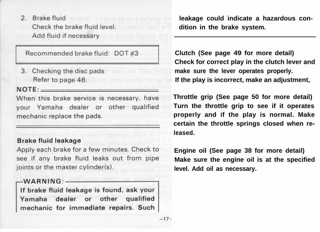
leakage could indicate a hazardous con-dition in the brake system.
Clutch (See page 49 for more detail)Check for correct play in the clutch lever andmake sure the lever operates properly.If the play is incorrect, make an adjustment,
Throttle grip (See page 50 for more detail)Turn the throttle grip to see if it operatesproperly and if the play is normal. Makecertain the throttle springs closed when re-
leased.
Engine oil (See page 38 for more detail)Make sure the engine oil is at the specifiedlevel. Add oil as necessary.
I1
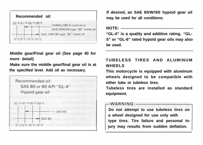
Recommended oil:I
Middle gear/Final gear oil (See page 40 formore detail)
Make sure the middle gear/final gear oil is atthe specified level. Add oil as necessary.
If desired, an SAE 80W/90 hypoid gear oil
may be used for all conditions.
NOTE:
“GL-4” is a quality and additive rating. “GL-
5” or “GL-6” rated hypoid gear oils may alsobe used.
TUBELESS T IRES AND ALUMINUM
WHEELSThis motorcycle is equipped with aluminum
wheels designed to be compatible with
either tube or tubeless tires.Tubeless tires are installed as standardequipment.
Do not attempt to use tubeless tires on
a wheel designed for use only with tube-type tires. Tire failure and personal in-
jury may results from sudden deflation.

Tubeless-type Wheel --t Tube-type
rWARNING:-
When using tube-type tires be sure to
install the proper tube also.
To insure maximum performance, long ser-
vice, and safe operation, note the followingprecautions:
1.
2.
3.
Always maintain proper air pressure as
described in the Chart on page 21.
Check tire pressure. before riding. adjustas necessary.Before operation, always check the tire
surfaces for wear and/or damage: lookfor cracks, glass, nails, metal frag-
ments, stones, etc. Correct any such
hazard before riding.
-19-

4. Always inspect the aluminum wheelsbefore a ride. Place the motorcycle onthe center stand and check for cracks,bends or warpage of the wheels. If anyabnormal condition exists in a wheel,consult your Yamaha dealer or otherqualified mechanic. Do not attempteven small repairs to the wheel. If awheel is deformed or cracked, it mustbe replaced.
5. Tires and wheels should be balancedwhenever either one is changed or re-placed. Failure to have a wheel assem-bly balanced can result in poor perform-ance, adverse handling characteristics,and shortened tire life.
6. After installing a tire, ride conservativelyto allow the tire to seat itself on the rimproperly. Failure to allow proper seatingmay cause tire failure resulting indamage to the motorcycle and injury tothe rider.
7. After repairing or replacing a tire, checkto be sure the valve stem lock nut issecurely fastened. If not, torque it asspecified.
Tightening torque: 0.15 m-kg (1.1 ft-lb)
The standard equipment tires originally fittedto the XS850G are suited to normal ridingand touring. They are not suited for sustainedhigh speed running or racing and must not beused for such purposes. Consider your ridingskill, road and weather conditions, and cor-rect weight distribution when loading yourmotorcycle. Securely pack your heaviestitems close to the center of the motorcycle.

-WARNING:1. This motorcycle is not designed to
pull a trailer or to be attached to a
sidecar. The accessories you choosefor your motorcycle should be de-signed specifically for it and should
be securely mounted in such afashion as to maintain the inherent
stability of the original design asmuch as possible. Yamaha has a full
line of sport and touring accessoriesdesigned specifically for this motor-
cycle. Please consider them beforemaking a purchase. Use of non-ap-
proved accessories may cause lossof handling stability and riding safe-ty. Consult your Yamaha dealer or
other qualified mechanic regardingthe consequences of using such
items.2. Proper loading of your motorcycle is
important for the handling, braking,
I and other performance and safetycharacteristics of your motorcycle.NEVER OVERLOAD YOUR MO-
TORCYCLE. Make sure the total
weight of the accessories, and etc.,does not exceed the maximum loadlimites. Operation of an overloaded
motorcycle could cause tire damage,an accident, and injury.

If a tire tread shows crosswise lines, it meansthat the tire is worn to its limit. Replace the
tire.
- W A R N I N G :It is dangerous to ride with a worn-out
tire. When a tire tread begins to showlines. Have Your Yamaha dealer or other
qualified mechanic replace the tire im-mediately. Brake pad replacement, tire,
and related wheel parts replacement
should be left to a Yamaha ServiceTechnician or other qualified mechanic.
If you must change your own tire, besure to use proper tools and procedures
as described in the Tubeless Tire andWheel Manual available from Your
Yamaha dealer.
Fittings/FastenersAlways check the tightness of chassis fittings
and fasteners before a ride. Use the chart on
page 37 to find the correct torque.
Lights and signals
Check the headlight, flasher lights, taillight,
brake light, meter lights and all the indicatorlights to make sure they are in working con-dition.
-22-

SwitchesCheck the operation of the headlight switch,turn switch, brake light switch, horn button,main switch, etc.
Battery (See page 58 for more detail)Check fluid level and top-up if necessary.Use only distilled water if refilling is neces-
sary.
FuelMake sure there is sufficient fuel in the tank.
-23-

OPERATION ANDIMPORTANT RIDING
POINTS
-CAUTION: I1.
2.
3.
Before riding this motorcycle, be-
come thoroughly familiar with alloperating controls and their func-tion. Consult your Yamaha dealer or
other qualified mechanic regardingany control or function you do notthoroughly understand.
Be careful where you store personal
items on the motorcycle. Avoidblocking the air cleaner intake orperformance will suffer.
Be careful not to put anything nearthe battery and its terminals. Elec-
trical failure and acid corrosion mayresult.
1.
2.
Never start your engine or let it runfor any length of time in a closed
area. The exhaust fumes are poison-
ous and can cause loss of conscious-ness and death within a short time.
Always operate your motorcycle inan area with adequate ventilation.
Before starting out, always be surethe side stand is up. Failure to re-tract the side stand completely can
result in a serious accident when
you try to turn a corner.
Starting and warming up a cold engine
1. Shift transmission into neutral.2. Turn the fuel petcock to “ON”.
3. Turn the ignition key to the “I” position
and the engine stop switch to “RUN”.

NOTE:At this time the neutral indicator light (green)and the oil pressure indicator light (red)should be on. If the lights do not come on askyour Yamaha dealer to inspect.
4. Operate the starter (CHOKE) by pullingup. Completely close the throttle grip.
5. Start the engine either by pushing thestarter button (or by using the kickcrank).
NOTE:If the engine fails to start, release the starterbutton, then push the starter button again.Pause a few seconds before the next attempt.Each cranking should be as short as possibleto preserve battery energy. Do not crank theengine more than 10 seconds on eachattempt.If the engine does not start with the startermotor, use the kick starter to start the engine.
-I
The oil pressure indicator light should
go off after the engine is started.If the indicator light flickers or remains
on, immediately stop the engine andcheck the engine oil level and for oil
leakage.
If necessary, replenish oil, restart the
engine, and check to see that the oilpressure indicator light goes off.
If the light does not go off even withsufficient oil in the crankcase, consult
your Yamaha dealer or other qualified
mechanic.
6. After starting the engine, push backthe starter half-way (warm-up position).
NOTE:To get maximum engine life, always “warm-up” the engine before starting off. Neveraccelerate hard with a cold engine!
-25-

7. After warming up the engine, turn off Starting a warm enginethe starter (push back the starter com- To start a warm engine, the starter (CHOKE)pletely). is not required.
Engine break-in
There is never a more important period inthe life of your motorcycle than the periodbetween zero and 1,000 km (600 mi). Forthis reason we ask that you carefully read thefollowing material. Because the engine isbrand new, you must not put an excessiveload on it for the first 1,000 km (600 mi).The various parts in the engine wear andpolish themselves to the correct operatingclearances. During this period prolonged fullthrottle operation, or any condition whichmight result in excessive heating of theengine, must be avoided.
-26-
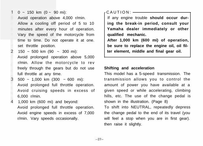
0 ~ 150 km (0 ~ 90 mi):Avoid operation above 4,000 r/min.Allow a cooling off period of 5 to 10minutes after every hour of operation.Vary the speed of the motorcycle fromtime to time. Do not operate it at one.set throttle position.150 ~ 500 km (90 ~ 300 mi):Avoid prolonged operation above 5,000r/min. Al low the motorcycle to revfreely through the gears but do not usefull throttle at any time.500 ~ 1,000 km (300 ~ 600 mi):Avoid prolonged full throttle operation.Avoid cruising speeds in excess of6,000 r/min.1,000 km (600 mi) and beyond:Avoid prolonged full throttle operation.Avoid engine speeds in excess of 7,000r/min. Vary speeds occasionally.
- C A U T I O N :If any engine trouble should occur dur-
ing the break-in period, consult yourYamaha dealer immediately or other
qualified mechanic.After 1,000 km (600 mi) of operation,
be sure to replace the engine oil, oil fil-ter element, middle and final gear oil.
Shifting and acceleration
This model has a 5-speed transmission. Thetransmission al lows you to control theamount of power you have available at agiven speed or while accelerating, climbinghills, etc. The use of the change pedal isshown in the illustration. (Page 8) 8 )To shift into NEUTRAL, repeatedly depressthe change pedal to the end of its travel (youwill feel a stop when you are in first gear).then raise it slightly.

To start out and accelerate: To decelerate:1
2
3
4
5
6
7.
Pull the clutch lever to disengage theclutch.
Shift into FIRST gear. The green neutralindicator light should go out.
Open the throttle gradually. and at thesame time, release the clutch lever slow-
ly.At the recommended shift point speed inthe table below, close the throttle, and at
the same time, pull in the clutch leverquickly.
Shift into SECOND gear. (Be careful notto shift into neutral.)
Open the throttle part way and graduallyrelease the clutch lever.
To accelerate use the same procedure toshift into the next higher gear accordingto the Recommended Shift Point Chartbelow.
Apply front and/or rear brakes to slowthe motorcycle.
When the motorcycle reaches 20 km/h(12.5 mi/h), shift to first gear.
Any time the engine appears about tostall or runs very roughly, pull in the
clutch and use the brakes to stop.When motorcycle is almost completely
stopped, shift to neutral.The green neutral indicator light shouldcome on.
Recommended Shift Point
-28-

CAUTION:1. Do not glide for long periods with
the engine off, and do not tow themotorcycle a long distance. Even
with gears in neutral, the transmis-sion is only properly lubricated when
the engine is running. Inadequatelubrication may damage the trans-
mission.2. Always use the clutch when chang-
ing gears. The engine, transmission,
and driveline are not designed to
withstand the shock load of forcedshifting and can be damaged byshifting without the clutch.
ParkingWhen parking, stop the engine and remove
the ignition key.
-WARNING:Select a parking place where the motor-
cycle is not apt to fall. Do not park the
motorcycle on a slope or soft ground;the motorcycle may overturn.

PERIODICMAINTENANCE AND
MINOR REPAIR
Periodic inspection, adjustment and lubrica-
tion will keep your motorcycle in the safest
and most efficient condition possible. Safety
is an obligation of the motorcycle owner.
The most important points of motorcycle in-
spection, adjustment and lubrication are ex-
plained in the following pages.
“Maintenance, replacement, or repair of
the emission control devices and systemsmay be performed by any repair establish-
ment or individual using any part which is
certified (if applicable).”
I f t h e o w n e r i s n o t f a m i l i a r w i t h
done by a Yamaha dealer or other
qualified mechanic.
PERIODIC MAINTENANCE
PROPER PERIODIC MAINTENANCE OF
YOUR MOTORCYCLE IS IMPORTANT TO
ITS GIVING YOU LONG, PLEASURABLE
SERVICE: ESPECIALLY IMPORTANT ARE
THE MAINTENANCE SERVICES RELATED
TO EMISSIONS CONTROL. THESE CON-
TROLS NOT ONLY FUNCTION TO ENSURE
CLEANER AIR BUT ARE ALSO VITAL TO
PROPER E N G I N E O P E R A T I O N A N D
MAXIMUM PERFORMANCE. IN THE FOL-
LOWING T A B L E S O F PERIODIC
MAINTENANCE, THE SERVICES RELATED
TO EMISSIONS CONTROL ARE GROUPED
SEPARATELY. THESE SERVICES REQUIRE
SPECIALIZED DATA, KNOWLEDGE, AND
EQUIPMENT. YAMAHA DEALERS ARE
TRAINED AND EQUIPPED TO PERFORM
THESE PARTICULAR SERVICES.

Tool kitThe service information included in this
manual is intended to provide you, the owner.
with the necessary information for complet-
ing some of your own preventive mainten-
ance and minor repairs. The tools provided in
the owner’s tool kit are sufficient for most of
these purposes. except that a torque wrench
is also necessary to properly tighten nuts and
bolts.
NOTE:
If you do not have a torque wrench available
during a service operation requiring one, take
your motorcycle to a Yamaha dealer or other
qualified mechanic to check the torque set-
tings and adjust them as necessary.
- W A R N I N G :
Modifications to this motorcycle not ap-
proved by Yamaha may cause loss of
performance, excessive emissions canrender it unsafe for use. Consult yourYamaha dealer or other qualified me-
chanic before attempting any changes.
-31-

PERIODIC MAINTENANCE EMISSION CONTROL SYSTEM
lnmal break-in Thereafter every
No Item Remarks 1,000 km 5,000 km 4.000 km 8,000 km(600 ml) (3,000 ml) (2.500 mi) (5.000 ml)
or 1 month or 7 months or 6 months or 12 months
1* Cam chain Check and adjust chain tension, 0 0 0I I I I I I
2* Valve clearanceCheck and adjust valve clearancewhen engine IS cold.
0 0
Check condition. Adjust gap. Clean. Replace.3 Spark plugs Replace after initial 0 0
1,300 km (8,000 mi).Every 12,000 km or18 months (7.500 mi).
4,x Crankcase Check ventilation hose for cracksventilation system or damage. Replace if necessary.
0 0
5* Fuel line Check fuel hose for cracksor damage. Replace if necessary.
0 0
Check for leakage.6* Exhaust system Retighten as necessary. 0 0
Replace gasket(s) if necessary.
7+ Carburetorsynchronization
Adjust synchronization of carburetors. I 0 I 0 I8* Idle speed Check and adjust engine idle speed.
Adjust cable free play if necessary.0 0
I
* It IS recommended that these items be serviced by your Yamaha dealer or other qualified mechanic
-32-
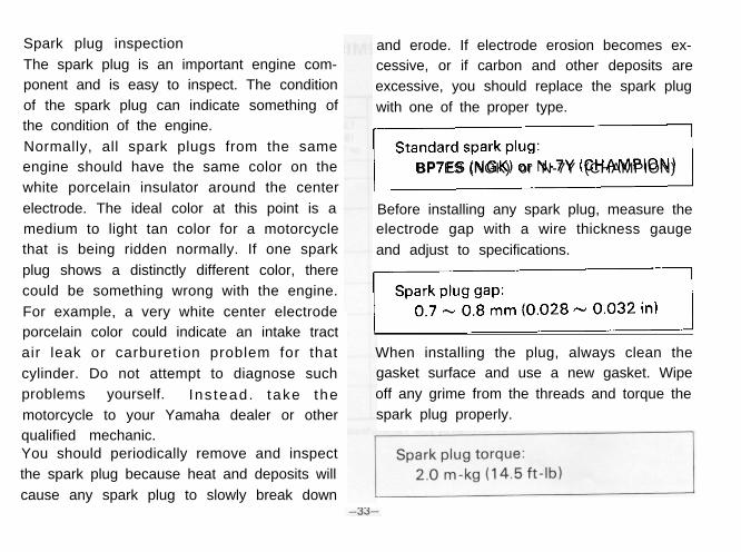
Spark plug inspection
The spark plug is an important engine com-
ponent and is easy to inspect. The condition
of the spark plug can indicate something of
the condition of the engine.
Normally, all spark plugs from the same
engine should have the same color on the
white porcelain insulator around the center
electrode. The ideal color at this point is a
medium to light tan color for a motorcycle
that is being ridden normally. If one spark
plug shows a distinctly different color, there
could be something wrong with the engine.
For example, a very white center electrode
porcelain color could indicate an intake tract
air leak or carburetion problem for that
cylinder. Do not attempt to diagnose such
problems yourself. Ins tead. take the
motorcycle to your Yamaha dealer or other
qualified mechanic.You should periodically remove and inspect
the spark plug because heat and deposits will
cause any spark plug to slowly break down
and erode. If electrode erosion becomes ex-
cessive, or if carbon and other deposits are
excessive, you should replace the spark plug
with one of the proper type.
7,
BP7ES (NGK) or N-7Y (CHAMPION)
Before installing any spark plug, measure theelectrode gap with a wire thickness gauge
and adjust to specifications.
-1
When installing the plug, always clean the
gasket surface and use a new gasket. Wipe
off any grime from the threads and torque the
spark plug properly.
NOTE:
If a torque wrench IS not available when you
are installing a spark plug. a good estimate of
the correct torque is l/4 to l/2 turns past
finger tights. Have the spark plug torqued tothe correct value as soon as possible with a
torque wrench.
-34

GENERAL MAINTENANCE/LUBRICATION
lnitial break-In Thereafter every
No Item Remarks Type 1,000 km 5,000 km 4,000 km 8,000 km 16,000 km(600 mi) (3.000 mi) (2,500 mi) (5,000 ml) (10,000 ml)
or 1 month or 7 months or 6 months or 12 months or 24 months
1 Engine oilWarm-up engine Refer tobefore draining page 38
0 0 0
2 O i l filter Replace - 0 0 0
3 Mrddlel/Frnalgear oil
ReplaceRefer topage 40
0 0
Dry type filter4 Air filter Clean with - 0 0
compressed air
5 * Brakesystem
Adjust free playReplace padsif necessary
- 0 0 0
6* Clutch Adjust free play - 0 0 0
7* Control and Apply chain lubeYamaha chain and
0meter cable thoroughly
cable lube or 0 01 0W/30 motor oil
Rear arm8* pivot
bearings
Check bearingsassembly forlooseness.
Medium
Moderately repackweight wheel Repack
every 16,000 kmbearing grease
(10,000 ml)
Brake pedalYamaha chain
9 and change Apply lightly and cable lube 0 0pedal shaft
or 10W/30motor oil

No. Item Remarks Type
Initial break-in Thereafter every
1,000 km 5,000 km 4.000 km 8,000 km 16.000 km(600 mi)or , month K3.~~;~ths (2 .500 mi) (5.000 mi) (10.000 mi)
or 6 months or 12 months or 24 month’
Center andYamaha chain
10 side stand Apply lightly and cable lubeor 10W/30 0 0
pivotsmotor oil
Front fork Drain completely. Yamaha fork, , +oil Refill to oil 10Wt or 0
specification equivalent
Check bearings
Steering ball assembly forlooseness. Medium weight
120 bearingModerately repack
wheel bearing 0 0 Repackand races
every 16,000 kmgrease.
(10,000 mi)
,3+ Wheelbearings
I4 Battery
Check bearingsfor smooth rotation.Replace if
- 0 0
necessary
Check specificgravity. Check -breather pipe for 0 0
proper operation
l It is recommended that these items be serviced by your Yamaha dealer or other qualified mechanic.
-36-
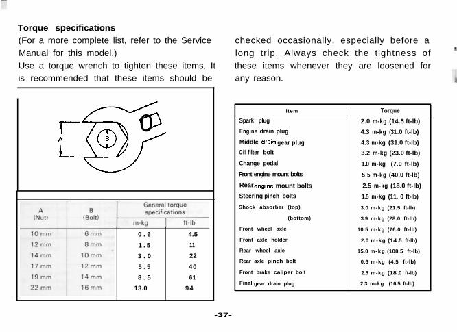
Torque specifications(For a more complete list, refer to the Service
Manual for this model.)
Use a torque wrench to tighten these items. It
is recommended that these items should be
t50 0i- B
0 . 6 4.5
1 . 5 11
3 . 0 22
5 . 5 40
8 . 5 61
13.0 94
checked occasionally, especially before a
long trip. Always check the tightness of
these items whenever they are loosened for
any reason.
Item Torque
Spark plug 2.0 m-kg (14.5 ft-lb)
Engine drain plug 4.3 m-kg (31.0 ft-lb)
Middle gear plug 4.3 m-kg (31.0 ft-lb)
Oi l filter bolt 3.2 m-kg (23.0 ft-lb)
Change pedal 1.0 m-kg (7.0 ft-lb)
Front engine mount bolts 5.5 m-kg (40.0 ft-lb)
Rear mount bolts 2.5 m-kg (18.0 ft-lb)
Steering pinch bolts 1.5 m-kg (11. 0 ft-lb)
Shock absorber (top) 3.0 m-kg (21.5 ft-lb)
(bottom) 3.9 m-kg (28.0 ft-lb)
Front wheel axle 10.5 m-kg (76.0 ft-lb)
Front axle holder 2.0 m-kg (14 .5 ft-lb)
Rear wheel axle 15.0 m-kg (108.5 ft-lb)
Rear axle pinch bolt 0.6 m-kg (4.5 ft-lb)
Front brake caliper bolt 2.5 m-kg (18 .0 ft-lb)
Final gear drain plug 2.3 m-kg (16.5 ft-lb)
-37-

Engine oil
1. Oil level measurement
a. Place the motorcycle on the centerstand. Warm up the engine for several
minutes.
NOTE:
Be sure the motorcycle is positioned straight
up when checking the oil level; a slight tilt
toward the side can produce false readings.
b. With the engine stopped, check the oil
level through the level window located
at the lower part of the right side
crankcase cover.
NOTE:
Wait a few minutes until the oil level settlesbefore checking.
c. The oi l level should be between
maximum and minimum marks. If the
level is lower. add sufficient oil to raise
it to the proper level.
2. Engine oil and oil filter replacement
a.
b.
C.
Start the engine and stop it after a few
minutes of warm-up.
Place an oil pan under the engine and
remove the oil filler cover.
Remove the drain plug and drain the oil.
-38-

d. Remove the oil filter bolt and filter ele-
ment.
e. Re-install the drain plug (make sure it is
tight).
Drain plug torque: 4.3 m-kg (31 .O ft-lb)
f. Install the new oil filter element. new“O” ring and filter cover, tighten the oil
filter bolt.
Oil filter bolt: 3.2 m-kg (23.0 ft-lb)
NOTE:Make sure the "O" ring is positioned properly.

g. Add oil through the oil filler hole.
With oil filter replacement:
Recommended oil: See page 17.
I h
I
After replacement of engine oil, and/or
oil filter, be sure to check the oil pres-
sure and for any oil leakage. The oil pre-
ssure indicator light should go off after
the engine is started.
Middle gear/Final gear oil
1.a.
b
Oil level measurement
Place the motorcycle on a level place
and place it on the center stand. The
engine should be cool (at atmospheric
temperature).
Remove the oil filler cap. Check the oil
level with level gauge (from tool kit) as
shown. The correct oil level is between
the two marks on each end of the level
gauge. Use the tool end marked “REAR”
for measuring the rear (final) gear case.
Use the end marked “MIDDLE” for
measuring the middle gear case.

NOTE:Middle gear and final gear oil can be checked
with same level gauge, which is in theowners tool kit.
Take care not to allow foreign material
2. Gear oil replacement
a. Place an oil pan under the transmissionfor the middle gear and under the final
gear case.b. Remove the middle and/or final gear oil
filler cap(s) and the drain plug(s), and
drain the oil.
- W A R N I N G :
When draining or filling, take care not to
allow foreign material to enter the mid-dle and/or final gear case. Do not allow
the gear oil to contact the tire and
wheel.
-41-

c. Reinstall and tighten the middle and/or
final gear drain plug(s). (See page 37 for
torque specifications.)
1 M,ddle gear drawn plug
d. Fill the gear case(s) to the specified
Oil capacity:
Middle gear case:
Approx. 0.375 lit (0.40 US qt)
Final gear case:
Approx. 0.30 lit (0.32 US qt)
Recommended oil: See page 18.
e. Reinstall the filler cap(s) securely.
Air filter
1. Removal
a. Remove the air filter case cap by loosen-
ing the wing bolt.
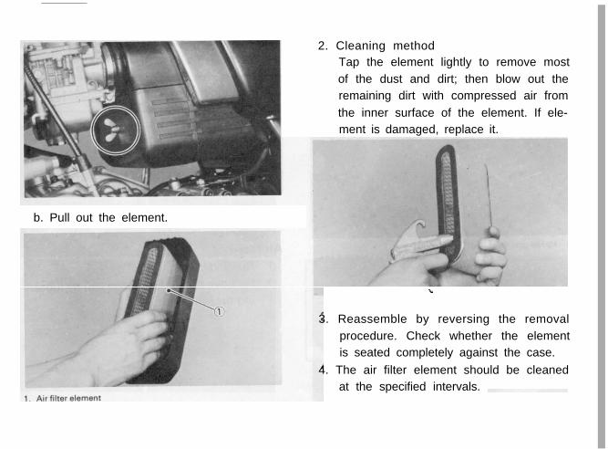
2. Cleaning methodTap the element lightly to remove most
of the dust and dirt; then blow out the
remaining dirt with compressed air from
the inner surface of the element. If ele-
ment is damaged, replace it.
b. Pull out the element.
3. Reassemble by reversing the removal
procedure. Check whether the element
is seated completely against the case.
4. The air filter element should be cleaned
at the specified intervals.
-43-

- C A U T I O N :
The engine should never be run withoutthe air cleaner element installed; exces-
sive piston and/or cylinder wear may re-sult.
Front brake adjustment
The front brake lever should be so adjusted
that it has a free play of 5 ~ 8 mm (0.2 ~
0.3 in) at the lever end.
1.
2.
3.
Loosen the lock nut on the brake lever.
Turn the adjuster so that the brake lever
movement at the lever end is 5 ~ 8 mm
(0.2 ~ 0.3 in) before the adjuster con-
tacts the master cylinder piston.
After adjusting. tighten the lock nut.
NOTE:
Check for correct play and make sure it is
working properly.
- W A R N I N G :
A soft or spongy feeling in the brakelever (and/or brake pedal) can indicate
the presence of air in the brake system.
This air must be removed by bleeding
the brake system before the motorcycle
is operated. Air in the system will resultin greatly diminished braking capabilityand can result in loss of control and an
accident. Have your Yamaha dealer or

other qualified mechanic inspect and
bleed the system if necessary.
Rear brake adjustment
- C A U T I O N :For the brake pedal position adjust-
ment, be sure to proceed as follows;(It is advisable to have your Yamahadealer or other qualified mechanic make
this adjustment.)
The rear brake pedal should be so adjusted
that it has a free play of 13~ 15 mm (0.51-0.59 in) from when the brake pedal is
stepped on to when the brake begins to
engage.
I, Adjuster bolt (for pedal height) 5. Footrest
2. Locknut 6. Pedal height 20 mm 10.78 an,
3. Locknut 7. Free play 13- 15mm
4. Brake rod (0.51-0.59 in)
1. Loosen the adjuster lock nut (for pedal
height).2. By turning the adjuster bolt clockwise
or counterclockwise, adjust the brakepedal position so that its top end is
approx. 20 mm (0.78 in) below the foot-
rest top end.-45-
3. Secure the adjuster lock nut.
4. Loosen the brake rod downward until
there is noticeable free play between
rod and master cylinder.
5. Turn in the brake rod until it lightly
touches the master cylinder, then turn it
out by approx. 1 and 3/4 turns (for pro-
per free play).6. Tighten the brake rod adjuster lock nut.
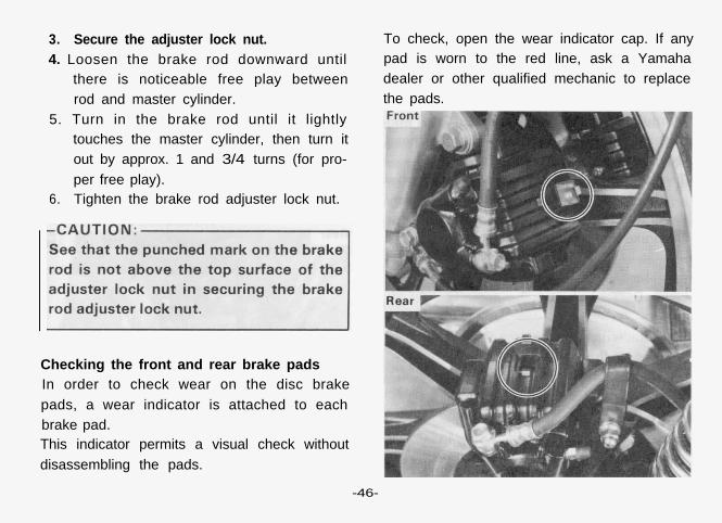
Checking the front and rear brake padsIn order to check wear on the disc brake
pads, a wear indicator is attached to each
brake pad.This indicator permits a visual check without
disassembling the pads.
To check, open the wear indicator cap. If any
pad is worn to the red line, ask a Yamaha
dealer or other qualified mechanic to replace
the pads.
-46-

Inspecting the brake fluid level
Insufficient brake fluid may allow air to enter
the ‘brake system, possibly causing the
brakes to become ineffective.
Before riding, check the brake fluid level and
replenish when necessary. and observe these
precautions:
1, Use only the designated quality brake
fluid; otherwise, the rubber seals may
deteriorate, causing leakage and poor
brake performance.
II
2. Refill with the same type of brake fluid;
mixing fluids may result in a harmful
chemical reaction and lead to poor per-
formance.
-47-

3.
4.
5.
Be careful that water does not enter the
master cylinder when refilling. Water
will significantly lower the boiling point
and may result in vapor lock.
Brake fluid may erode painted surfaces
or plastic parts. Always clean up spilled
fluid immediately.
Have a Yamaha dealer or other qualified
mechanic check the cause if the brake
fluid level goes down.
Brake fluid replacement
1.
2.
3.
a
Complete fluid replacement should be
done only by trained Yamaha service
personnel or other qualified mechanic.
Complete fluid replacement should be
done whenever the caliper cylinder or
master cylinder is disassembled, or the
fluid becomes seriously contaminated.
Replace the fo l lowing components
whenever damaged or leaking. Also:
Replace all brake seals every two years.
b. Replace all brake hoses every four years.
Brake light switch adjustment
The brake light switch is operated by move-
ment of the brake pedal. To adjust, hold the
main body of the switch with the hand so it
does not rotate and turn the adjusting nut.
Proper adjustment is achieved when the
brake light comes on slightly before the
brake begins to take effect.
1. Main body 2 Ad,“stlng nut
-48-

Clutch adjustmentThis model has a clutch cable length adjuster
and a clutch mechanism adjuster. The cable
length adjuster is used to take up slack from
cable stretch and to provide sufficient free
play for proper clutch operation under vari-
ous operating conditions. The clutch mecha-
nism adjuster is used to provide the correct
amount of clutch “throw” for proper dis-
engagement, Normally, once the mechanism
is properly adjusted, the only adjustment
required is maintenance of free play at the
clutch handlebar lever.
1. Free play adjustment
Loosen the handlebar lever adjuster
lock nut, Next turn the length adjuster
either in or out until proper lever free
play is achieved.
,
1. Locknut 2. Adjustera. 2- 3 mmlO08- 0.12 Ill)
2. Mechanism adjustment
The second adjustment is located be-
hind the adjusting cover. Removing the
cover will expose the adjuster and lock
nut.Loosen the lock nut, rotate the adjuster
in until it lightly seats against the clutch
push rod that works with the adjuster to
operate the clutch. Back the adjuster
out l/4 turn and tighten the lock nut.
-49-

This adjustment must be checked be-
cause heat and clutch wear will affect
this free play, possibly enough to cause
incomplete clutch operation. Recheck
clutch cable adjustment at the handle-
bar after adjusting.
Cable inspection and lubrication
1. Damage to the outer housing of the
various cables may cause corrosion.
Often free movement will be obstruct-
ed. An unsafe condition may result, S O
replace such cables as soon as possible.
2. If the inner cables do not operate
smoothly, lubricate or replace them.
Throttle cable and grip lubrication
The throttle twist grip assembly should be
greased when the cable is lubricated, since
the grip must be removed to get at the end of
the throttle cable. Two screws clamp the
throttle housing to the handlebar. Once these
two are removed, the end of the cable can be
held high to pour in several drops of lubri-
cant. With the throttle grip disassembled,
coat the metal surface of the grip assembly
with a suitable all-purpose grease to cut
down friction.
Rear arm pivot bearingsThe swing arm must pivot freely on its bear-
ings but not have any excess play. Have your
Yamaha dealer or other qualified mechaniccheck rear arm pivot bearing operation ac-
cording to the General Maintenance Sched-ule.
Brake and change pedal/Brake and clutchlever
Lubricate the pivoting parts of each lever andpedal.
Center and side stand pivots
Lubricate the center and side stands at their
pivot points.
Front fork oil change
,--WARNING:
1.
2.
Fork oil leakage can cause loss ofstability and safe handling. Have any
problem corrected before operating
the motorcycle.Securely support the motorcycle so
there is no danger of it falling over.
1. Raise the motorcycle or remove the
front wheel so that there is no weighton the front end of the motorcycle.
Remove the handlebar.
2. Remove the rubber cap from the top of
each fork.
-51-

1. Rubbercap
3. Keep the valve open while pressing it
for several seconds so that the air can
be let out of the inner tube.
1. Push
I-
-52-
4.
5.
The spring seat and fork spring are re-
tained by a stopper ring (spring wire
circlip). It is necessary to depress the
spring seat and fork spring to remove
the stopper ring. Remove the stopper
ring by carefully prying out one end with
a small screwdriver.
Place an open container under each
drain hole. Remove the drain screw
from each outer tube.
- W A R N I N G :
Do not allow oil to contact the discbrake components. If any oil should
contact the brake components it mustbe removed before the motorcycle is op-
erated. Oil will cause diminished brak-
ing capacity and will damage the rubbercomponents of the brake assembly.

6.
7.
8.
When most of the oil has drained,
slowly raise and lower the outer tubes
to pump out the remaining oil.
Inspect the drain screw gasket. Replace
if damaged. Reinstall the drain screw.
Pour the specified amount of oil into the
fork inner tube.
Front fork oil (each fork):
195 cc (6.60 oz)
Yamaha Fork Oil 10 wt or equivalent
9. After filling. slowly pump the forks up
and down to distribute the oil.
10. Inspect the “O-ring” on the spring seat.
Replace “O-ring” if damaged.

11. Reinstall the spring seat and fill the fork
with air using a manual air pump or
other pressurized air supply. Refer to
“Front fork and rear shock absorber ad-
justment” for proper air pressure ad-
justing.
Maximum air pressure:
2.5 kg/cm* (36 psi)
Do not exceed this amount
Front fork and rear shock absorber adjust-ment
Front fork:
1. Elevate the front wheel by placing the
motorcycle on the center stand.
NOTE:
When checking and adjusting the air pres-
sure, there should be no weight on the front
end of the motorcycle.
2. Remove the rubber cap from the top of
each fork.
3. Using the air gauge, check and adjust
the air pressure.If the air pressure is increased, the
suspension becomes stiffer and if de-
creased, it becomes softer.
To increase:
Use a manual air pump or other pres-
surized air supply.
To decrease:
Release the air by pushing the valve pin.
-54-

Standard air pressure:
0.4 kg/cm* (5.7 psi)
Maximum air pressure:
2.5 kg/cm’ (36 psi)Minimum air pressure: Zero
* Never exceed the maximum pressure,
or oil seal damage may occur.
* The difference between both the left
and right tubes should be 0.1 kg/cm’
(1.4 psi) or less.
4. Install the rubber caps securely.
Rear shock absorber:
1, Spring preload
If the spring seat is raised, the spring
becomes stiffer and if lowered, it be-
comes softer.
Standard position - AA. position - Softest
E. position - Stiffest
-55-
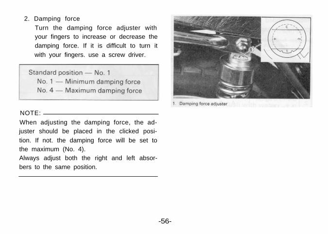
2. Damping force
Turn the damping force adjuster with
your fingers to increase or decrease the
damping force. If it is difficult to turn it
with your fingers. use a screw driver.
NOTE:
When adjusting the damping force, the ad-
juster should be placed in the clicked posi-
tion. If not. the damping force will be set to
the maximum (No. 4).
Always adjust both the right and left absor-
bers to the same position.
-56-

Recommended combinations of the front Use this table as guidance to meet specific
fork and the rear shock absorber. riding conditions and motorcycle load.
Steering inspection
Periodically inspect the condition of the try to move it forward and backward. If anysteering. Worn out or loose steering bearings free play can be felt, ask a Yamaha dealer or
may be dangerous. other qualified mechanic to inspect and ad-
Place a block under the engine to raise the just the steering assembly.front wheel of the motorcycle off the ground: Inspection is easier if the front wheel is re-
then hold the lower end of the front fork and moved.-57-

Securely support the motorcycle so
there is no danger of it falling over.
Wheel bearingsIf the wheel bearings in the front or rear
wheel allow play in the wheel hub, or if thewheel does not turn smoothly, have your
Yamaha dealer or a qualified mechanic in-spect the wheel bearings. The wheel bear-ings should be inspected according to the
General Maintenance Schedule.
Battery
Check the level of the battery fluid and see ifthe terminals are tight. Add distilled water ifthe fluid level is low.
- W A R N I N G :
Battery electrolyte is poisonous anddangerous, causing severe burns, etc.
Contains sulfuric acid. Avoid contactwith skin, eyes or clothing. Antidote:EXTERNAL-Flush with water.INTERNAL-Drink large quantities of
water or milk. Follow with milk of
magnesia, beaten egg or vegetable oil.Call physician immediately.Eyes: Flush with water for 15 minutes
and get prompt medical attention.Batteries produce explosive gases.
Keep sparks, flame, cigarettes, etc.away. Ventilate when charging or using
in closed space. Always shield eyeswhen working near batteries. KEEP
OUT OF REACH OF CHILDREN.

Replenishing the battery fluid
A poorly maintained battery will deteriorate
quickly. The battery fluid should be checkedat least once a month.
1. The level should be between the upperand lower level marks. Use only distilledwater if refilling is necessary.
NOTE:
Normal tap water contains minerals which
are harmful to a battery; therefore, refill onlywith distilled water.
2.
3.
4.
When the motorcycle is not to be usedfor a month or longer, remove the bat-
tery and store it in a cool, dark place.Completely recharge the battery beforereusing.
If the battery is to be stored for a longer
period than the above, check the specif-ic gravity of the fluid at least once amonth and recharge the battery whenit is too low.
Always make sure the connections are
correct when putting the battery back inthe motorcycle.
Make sure the breather pipe is properlyconnected and is not damaged orobstructed.

Headlight
This motorcycle is equipped with a quartz
bulb headlight. If the headlight bulb burns
out. replace the bulb as follows:
1. Headlight bulb replacement
a. Remove the 2 screws holding the lightunit assembly to the headlight body.
b. Disconnect the lead wires and remove
the light unit assembly.
c. Turn the bulb holder counterclockwise
and remove the defective bulb.
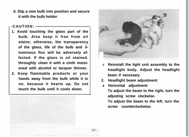
d. Slip a new bulb into position and secureit with the bulb holder
-CAUTION:1. Avoid touching the glass part of the
bulb. Also keep it free from oil
stains; otherwise, the transparencyof the glass, life of the bulb and il-
luminous flux will be adversely af-fected. If the glass is oil stained.throughly clean it with a cloth moist-
ened with alcohol or lacquer thinner.
2. Keep flammable products or yourhands away from the bulb while it is
on. because it hearts up. Do nottouch the bulb until it cools down.
e
2.a
Reinstall the light unit assembly to theheadlight body. Adjust the headlight
beam if necessary.
Headlight beam adjustmentHorizontal adjustment:To adjust the beam to the right, turn the
adjusting screw clockwise.
To adjust the beam to the left. turn thescrew counterclockwise.

b. Vertical adjustment:
1 ) Loosen the adjusting screw under the
headlight body.
2) Adjust vertically by moving the head-
light body. When proper adjustment is
determined, retighten the adjusting
screw.
Fuse replacement
1. The fuse block is located under the seat.
2. If any fuse is blown, turn off the ignition
switch and the switch in the circuit in
question and install a new fuse of
proper amperage.
Then turn on the switches, and see if
the electrical device operates. If the fuse
immediately blows again, consult your
Yamaha dealer or other qual i f iedmechanic.

- W A R N I N G :
Do not use fuses of a higher amperagerating than those recommended. Sub-
stitution of a fuse of improper rating can
cause extensive electrical system dam-age and possible fire.
Front wheel removal1. Place the motorcycle on the center
stand.
2. Remove the front fender securing bolts
and remove the fender.
3. Remove the cotter pin and wheel axle
nut.
4.
5.
Loosen the wheel axle holder nuts.Remove the axle shaft, In this case,
make sure the motorcycle is properly
supported.
NOTE:
Do not depress the brake lever when the
wheel is off the motorcycle as the brake pads
will be forced to shut.
-63-
6. Lower the wheel until the discs come
off the calipers. Turn the calipers out-ward so they do not obstruct the wheel
and remove the wheel.
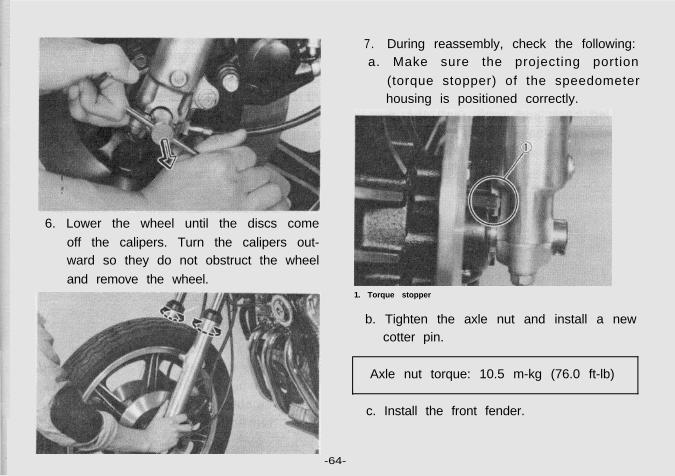
7. During reassembly, check the following:a. Make sure the projecting portion
(torque stopper) of the speedometerhousing is positioned correctly.
c. Install the front fender.
-64-
1. Torque stopper
b. Tighten the axle nut and install a newcotter pin.
Axle nut torque: 10.5 m-kg (76.0 ft-lb)

d. Before tightening the holder nuts, strokethe front forks several times to make
sure of proper fork operation. With the
axle holder nuts loose, work the left fork
leg back and forth until the proper
clearance between the disc and caliper
bracket are obtained.
e. Tighten the axle holder nuts. First
tighten the nut on the front end of the
axle holder, then tighten the nut on the
rear end.
1 1st 2. 2nd 3 Gap
Rear wheel removal
1. Place the motorcycle on the side stand,
and remove both the top and bottom
nuts which mount the left side rear
shock absorber. Then set free only the
bottom end of the shock absorber.
-65-

Hook one end of the wire tool (contain-
ed in the owner’s tool kit) to the hook
attached to the frame.
Apply your weight to the rear part of theseat, and compress the rear shock ab-
sorbers by pulling up the right side of
the swing arm with your hand, then
hook the other end of wire tool to the
swing arm as shown.
4.
5.
With the wire tool in this position, place
the motorcycle on the center stand.
Remove the seat and unscrew the rear
fender instal lat ion bol ts unt i l their
threaded portion is completely out.
Reinsert those bolts as stoppers to holdthe rear fender up.
1. Installation bolts
6. Remove the axle nut cotter pin and axlenut.
-66-

7. Loosen the rear axle pinch bolt.
8. While supporting the brake caliper, pull
out the rear axle.
9. Pull out the rear brake torque stopper
plate from where it is retained the
rear arm. Next, suspend the caliper as-sembly with the big end of the wire tool
(contained in the owner’s tool kit) hang-
ing on the rear stay and the small end
on the metal area of the brake caliper
hose joint.
-67-

1. Rubber retainer 3. Rear arm
2. Torque stopper plate
10. Move the wheel to the right side to
separate it from the final gear case and
remove the rear wheel.
NOTE:
Do not depress the brake pedal when the
wheel is off the motorcycle as the brake pads
will be forced to shut.
1 Wire tool
11. To install the rear wheel, reverse the
removal procedure.
-68-

NOTE:
Before installing the rear wheel, apply a light
coating of lithium base grease to the final
gear case splines.
When installing the rear wheel, be sure the
splines on the wheel hub fit into the final
gear case.
Make sure there is enough gap between the
brake pads before inserting the brake disc.
1 Rear wheel hub splines
2. Final gear case splines
Tightening torque:Axle nut: 15.0 m-kg (108.5 ft-lb)
Axle pinch bolt: 0.6 m-kg (4.0 ft-lb)
Shock absorber:Top mount: 3.0 m-kg (21.5 ft-lb)
Bottom mount: 3.9 m-kg (28.0 ft-lb)
- C A U T I O N :Always use a new cotter pin on the rear
axle nut.
-Carburetor adjustment:
The carburetor is a vital part of the en-gine and its emission control system.
Adjusting should be left to your Yamaha
dealer or other qualified mechanic with
the professional knowledge, specialized
data and equipment to do so properly.
-69-

TroubleshootingAlthough Yamaha motorcycles are given a
rigid inspection before shipment from the
factory, trouble may occur during operation.
If this happens, check the motorcycle in
accordance with the procedures given in thefollowing chart. If repair is necessary, ask a
qualified mechanic such as your Yamaha de-
aler for assistance. The skilled technicians at
your Yamaha dealer are trained and equip-
ped to perform the necessary maintenance
and repair work. For replacement parts,
Yamaha recommends you use Genuine
Yamaha Parts, or parts you know are equiva-
lent in quality.
Any problem in the fuel, compression or igni-
tion system can cause poor starting, exces-
sive emissions, engine damage, or loss of
power while riding. The troubleshooting
chart describes a quick and easy series of
system checks to locate the problem.
-70-


MISCELLANEOUSConsumer information
STOPPING DISTANCE
These figures indicate braking performance that can be met or exceeded by the vehicles to which they apply.without locking the wheels. under different conditions of loading and with partial failures of the braking sys-tem The information presented represents results obtainable by skilled drivers under controlled road andvehicle conditions and the information may not be correct under other conditions.
Description of vehicles to which this table apples. Yamaha motorcycle XS850G
A. Fully Operational Service Brake Load
Light 178
Maximum 189
IOTE:‘he statement above is required by U.S. Federal law. 0 100 2 0 0 300 (Feet)Partial failures of the braking system do not apply to thishart. Stopping distance in feet from 60 mi/h
-75-

ACCELERATION AND PASSING ABILITY
These figures indicate passing times and distances that can be met or exceeded by the vehicles to which theyapply in the situations diagrammed below.The low-speed pass assumes an initial speed of 20 mi/h and a limiting speed of 35 mi/h. The high-speedpass assumes an initial speed of 50 mi/h and a limiting speed of 80 mi/h.NOTICE: The information presented represents results obtainable by skilled drivers under controlled road
and vehicle conditions, and the information may not be correct under other conditions.
Description of vehicles to which this table applies Yamaha motorcycle XS850G
Summary tableLow-speed p a s s . . . . . . . . . . . . . . . . . . . . . . . . . . . . . . . . . . . . . . 3 5 1 feet: 7.1 secondsHigh-speed pass ,,.,,................... ,........... 868 feet : 8 .1 seconds
LOW-SPEED HIGH-SPEED
INITIALSPEED 20 mi/h
INITIALSPEED 50 mi/h
LIMITINGSPEED. 80 mi/h
TOTAL PASSlNG DISTANCE. FEETTOTAL PASSlNG TIME SECONDS
CONSTANT 50 mi/h

CLEANING ANDSTORAGE
A. CLEANINGFrequent thorough cleaning of your motor-cycle will not only enhance its appearancebut will improve general performance andextend the useful life of many components.
1.a .
b .
2.
3.
Before cleaning the motorcycle:Block off end of exhaust pipe to preventwater entry: a plastic bag and strongrubber band may be use.Make sure spark plug and gas cap areproperly installed.If engine case is excessively greasy.apply degreaser with a paint brush. DO
not apply degreaser to wheel axles.Rinse dirt and degreaser off with agarden hose, using only enough hosepressure to do the job. Excessive hosepressure may cause water seepage and
-72-
contamination of wheel bearings, frontforks, brake calipers, and transmissionseals. Many expensive repair bills haveresulted from improper use of high pres-sure detergent applications such asthose available in coin-operated carwashes.Once the majority of the dirt has beenhosed off, wash all surfaces with warmwater and mild, detergent type soap. Anold tooth brush or bottle brush is handyto reach hard-to-get-to places.Rinse motorcycle off immediately withclean water and dry all surfaces with achamois, clean towel, or soft absorbentcloth.Chrome-plated parts such as handle-bars, fenders, forks. etc., may be furthercleaned with automotive chromecleaner.Clean the seat with a vinyl upholsterycleaner to keep the cover pliable andglossy.

8. Automotive-type wax may be applied toall painted and chrome-plated surfaces.
Avoid combination cleaner-waxes.Many contain abrasives which may mar
paint or protective finish on the fuel tankand side covers.
9. After finishing, start the engine im-mediately and allow to idle for several
minutes.
B. STORAGELong term storage (60 days or more) of yourmotorcycle will require some preventive
procedures to insure against deterioration.After cleaning the machine thoroughly, pre-
pare for storage as follows:1. Drain fuel tank, fuel lines, and carbure-
tor float bowl.2. Remove empty fuel tank, pour a cup of
10 /30 or 20W/40 motor oil in tank.
shake the tank to coat the inner sur-faces thoroughly and drain off excessthe oil. Reinstall the tank.
3. Remove the spark plug. pour about one
t a b l e s p o o n o f 10W/30 o r 20W/40motor oil in the spark plug hole and re-install the spark plug. Kick the engine
over several times (with the ignition off)to coat the cylinder walls with oil.
- W A R N I N G :When using starter motor to crank theengine, remove spark plug wires andground them to prevent sparking.
4. Lubricate all control cables.
5. Block up the frame to raise both wheelsoff the round.
6. Tie a plastic bag over the exhaust pipeoutlet to prevent moisture entering.
7. If storing in humid or salt-air atmos-
phere, coat all exposed metal surfaceswith a light film of oil. Do not apply oil
to any rubber parts or the seat cover.8. Remove the battery and charge it. Store
it in a dry place and recharge it once a

month, Do not store the battery in an
excessively warm or cold place (lessthan 0°C (32°F) or more than 30°C
(86°F)).
NOTE:Make any necessary repairs before storingthe motorcycle.
-74-

SPECIFICATIONSGeneral specifications
MODEL
Dimension:Overall lengthOverall widthOverall heightWheelbaseMlnlmum road clearance
Weight:Net
Performance:MInimum turning radiusClimbing capacity
Engine:TypeEngine modelCylinderDisplacmentBore x strokeCompressIon ratio
Starting system
XS850G
2,175 mm (85.6 in)900 mm (35.4 in)
1,190 mm (46.9 in)1,450 mm (57.1 in)
140 mm /(5.5 in)
241 kg (531 lb)
2,400 mm (94.5 in)26°
4 stroke. gasoline. air-cooled, DOHC3J33-cylinder in-line, Forward inclined826 cc (27.94 cu.in)71.5 x 68.6 mm (2.815 x 2.701 in)9 . 2 : 1Electric and ck kick starter
-77-

MODEL
Ignition system
Fuel tank capacity
Engine oil quantity
Lubricating system
Battery type/capacity
Generator
Spark plug
Carburetor
Air cleaner
Clutch type
Transmission:
Primary reduction system
Primary reduction ratio
Secondary reduction system
Secondary reduction ratio
Gear box type
Operation system
Gear ratio: First
Second
Third
Fourth
Fifth
XS850G
Battery ignition (Full transistor ignition)
Total: 17 lit (4.5 US gal)
Reserve: 3 lit (0.8 US gal)
Total amount: 3.7 lit (3.91 US qt)
Periodic oil change: 2.8 lit (2.96 US qt)
Wet sump
YB14L/12V, 1 4 A H
A.C. generator
BP7ES (NGK) or N-7Y (CHAMPION)
HSC34-II x 3
Dry type element
Wet, multiple-disc
HY-VO chain + gear
45/27 (1.666)
Shaft drive
35/31 x 19/18 x 32/11 = 3 . 4 6 6
Constant mesh, 5-speed forward
Left foot operation
32/14 (2.285)
27/l7 (1.588)
26/20
23/21 (1.095)
22/23 (0.956)
-78-

MODEL XS850GI
Tubular. double-cradleCasterTrailFrontRearFrontRearFrontRearFrontRear
FlasherHigh beamNeurl it,._^I
Headlight outi weOil p r e s s u r e,.udl”.lM e ter light
131 mm (5.16 in)3.25H 19-4PR4.50H 17-4PRDisc brake/Right hand operationDisc brake/Right foot operationTelescopic fork (Pneumo-mechanical)
Coil/air spring, oi l damper
1 2V. 60W/55W (Quartz bulb)12V. 8W (3CP)/27W (32CP) x 212V. 27W (32CP) x 412V. 3.4W x 212V. 3.4W x 112V. 3.4W x 112V. 3.4W x 1
Chassis:Frame typeSteering:
Tire size:
Braking system:
Suspension:
Shock absorber:
Electrical:HeadlightTail/brake lightFlasher lightPilot lights:
II
L
*
-79-