xv-15 low-noise terminal area operations testing - … low-noise terminal area operations testing...
TRANSCRIPT

NASA / CR- 1998-206946
XV-15 Low-Noise Terminal Area Operations
Testing
B. D. Edwards
Bell Helicopter Textron, Inc., Fort Worth, Texas
National Aeronautics andSpace Administration
Langley Research CenterHampton, Virginia 23681-2199
Prepared for Langley Research Centerunder Contract NAS 1-20094
February 1998
https://ntrs.nasa.gov/search.jsp?R=19980047341 2018-05-12T12:16:59+00:00Z

Available from the following:
NASA Center for AeroSpace Information (CASI)
800 Elkridge Landing Road
Linthicum Heights, MD 21090-2934
(301) 621-0390
National Technical Information Service (NTIS)
5285 Port Royal Road
Springfield, VA 22161-2171
(703) 487-4650
TABLE OF CONTENTS
Paragraph Va e
1. INTRODUCTION ._..................................................................................................................... 1
1.1 PURPOSE OF TEST .............................................................................................................. 1
2. TEST DESCRIPTION ................................................................................................................. 3
2.1 TEST S1TE ............................................................................................................................. 3
2.2 PERSONNEL/CREW ASSIGNMENTS .............................................................................. 3
2.3 TEST SETUP ......................................................................................................................... 6
2.3.1 Acoustic Measurements ................................................................................................... 7
2.3.2 Meteorological Measurements ......................................................................................... 9
2.3.3 Position Tracking System ............................................................................................... 9
2.3.4 Aircraft Parameters ........................................................................................................ 16
2.4 PHASE 1. "'LINEAR" MICROPHONE ARRAY TESTING .............................................. 16
2.4.1 Flight Conditions ........................................................................................................... 16
2.4.2 Meteorological Conditions - Phase 1 Testing ................................................................ 22
2.4.3 XV- 15 Position/Aircraft Parameters .............................................................................. 22
2.5 PHASE 2. "DISTRIBUTED" MICROPHONE ARRAY TESTING ................................... 22
2.5.1 _____KhtConditions ........................................................................................................... 22
2.5.2 Meteorolo_cal Conditions ............................................................................................. 242.5.3 X'V- 15 Position/Aircraft Parameters .............................................................................. 24
3. RESULTS/CONCLUDING REMARKS .................................................................................. 25
iii
LIST OF FIGURES
1
2
3
4
5
6
7
8
9
10
11
12
13
14
15
16
17
18
19
XV-15 Noise Test History Leading Up to the Present Test ........................................... 2
XV- 15 Over Helipad Constructed for Tests .................................................................. 3
XV-15 Aircraft #2 (NT03NA) Used in Noise Tests ..................................................... 5
XV- 15 Flight Envelope .................................................................................................. 6
XV-15 Noise Test Setup (Phase 1 Test) ........................................... . ............................ 7
Phase 1 Testing: Linear Microphone Array ................................................................... 8
Phase 2 Testing: Distributed Microphone Array .......................................................... 8
NASA's Weather Tower .............................................................................................. 10
NASA-Ames Mobile Optical Tracker ......................................................................... 11
XV- 15 Cockpit ............................................................................................................ 12
Headquarters Trailer with Test Personnel ................................................................... 12
XV-15 Details .............................................................................................................. 13
Optical Tracking Station .............................................................................................. 14
Flight Track Marker..".i...i .............. i.... ii.i ....... ..i ..................................... '. ................... 15
Linear Microphone Array During Phase 1 Testing ...................................................... 17
Phase 1 Level Flight .................................................................................................... 19
Phase 1 Approaches ..................................................................................................... 20
Phase 1 Takeoffs .......................................................................................................... 21
Bell Helicopter Textron Large Noise Data Display KV-15 Tests at
Waxahachie (Oct-Nov 1995) ....................................................................................... 26
iv

LIST OF TABLES
Table
1
2
Paee
XV-15 TILTROTOR DESIGN AND OPERATING PARAMETERS ....................... 5
FLIGHT DATA RECORDED DUR/NG TESTS ...................................................... 16
V


1-- INTRODUCTION
This report describes noise testing of the XV-15 tiltrotor aircraft conducted by the National
Aeronautics and Space Administration (NASA) and Bell Helicopter Textron, Incorporated
(BHTI) during October and November 1995, at BHTI's test site near Waxahachie, Texas.
NASA-Langley Research Center was responsible for overall test direction as well as acoustic and
meteorological measurements. NASA-Ames provided aircraft position tracking. BHTI supported
the tests by providing the XV-15 aircraft and test site coordination under contract NAS1-20094,
Task 3. As an additional effort under this contract, BHTI also developed a computerized
visualization tool to display instantaneous noise contours concurrently with XV-15 position and
nacelle angle.
This report documents the test setup and procedures used during this program. Acoustic and
flight profile data are not included, since these were recorded and analyzed by NASA. Questions
concerning the complete database generated during this test should be addressed to Mike
Marcolini of NASA-LaRC.
1.1 PURPOSE OF TEST
Noise impact is currently considered to be a major obstacle to developing the tiltrotor's full
potential within the civil transportation system. If this potential is to be realized, noise reduction
must be considered in each new tiltrotor design, and low-noise operating techniques must be
defined for all tiltrotors. The purpose of this test was to support the noise reduction design and
operation of future tiltrotors. The stated objectives were to:
- provide a comprehensive acoustic database for NASA and U.S. industry
- validate noise prediction methodologies, and
- develop and demonstrate low-noise flight profiles.
This is the latest in a series of X'V-15 noise tests aimed at understanding the noise characteristics
of the relatively new tiltrotor aircraft (References 1 through 4). The timeline shown in Figure 1
illustrates the history leading up to the current test. Primary emphasis was given to the approach
flight condition where blade-vortex interaction (BVI) dominates the noise signature. Since this
flight condition influences community noise impact more than any other, an understanding of the
noise generating processes is required to guide the development of low noise flight operations.
This, in turn, can substantially reduce the tiltrotor's impact on the community.
1

1980
• Level Flight @ 100'• 5 NASA mics
1982: Crow'sLanding... NASA-Ames/BHTI
Level Flight @ 100', 200', 500'Approach @ 3, 5, 9 dog.;
• 5 NASA talcs !some cerLpos'ns)
Crow'sLanding... NASA-Ames/BHTI
1985
1990
1995
Figure 1.
• Level Right @ 250', 500', 750' • Hover• Approach @ 3, 6, 9 dog.; • Takeoff
• 20 NASA rnics (grad); g BHTI mics (includes cerLpos'ns)
1988:Maypead,TX... NASA-LaRC,/BHTI
• Level Right @ 250', 500', 750' • Hover
• Approach @ 3, 6, 9 clog.; • Takeoff• 30 NASA mics (gmd); 6 BHTI talcs (includes cerLpos'ns)
1995:Waxah_ TX.,. NA.SA-LaRC/BH11
[] Segmented approaches TBD• 30 NASA mics (grnd)
1997:Waxahachle,TX... NASA-LaRC/BHTI
XV-15 Noise Test History Leading Up to the Present Test
2

2-- TEST DESCRIFrION
The test consisted of two distinct phases: Phase 1 provided an acoustic database for validating
analytical noise prediction techniques, and Phase 2 directly measured large area noise impact
over a broad range of operating profiles.
2.1 TEST SITE
Testing was performed in a rural area near the town of Waxahachie, Texas, on an available tract
of land that had been the site of the former Superconducting Super Collider (SSC). The site is
sufficiently remote that the ambient noise levels were low, 35-40 dBA, yet near enough to the
Dallas-Fort Worth area to allow flight operations out of BHTI's Arlington flight facility. The
terrain is flat with few trees, and during the test the ground was covered with short, mowed grass.
Since the XV-15 is not equipped with a particle separator, a helipad was constructed for hovering
flight. Figure 2 shows the XV-15 hovering above this pad. The terrain in the background is
typical of the topography at this site.
Figure 2. XV-15 Over Helipad Constructed for Tests
2.2 PERSONNEL/CREW ASSIGNMENTS
As stated earlier, NASA-LaRC was responsible for the overall test direction and for selecting test
points and flight procedures that would receive the highest priority. These selections were madewith the assistance from BHTI and other industry members and from NASA-Ames/Army
handling qualities/simulation personnel, notably Mr. Bill Decker. Handling qualities were
consideredan integral part of the program to ensm'e that any "low noise" flight operations were
practical ones which could actually be used in a commercial tiltrotor.
NASA-LaRC provided equipment and personnel for acoustical (30 microphone stations) and
meteorological measurements during the test, and for overnight analysis of each dataset. The
NASA-LaRC team included personnel under contract from Wyle and lockheed.
NASA-Ames supported the test by providing the XV-15 position tracking. A laser optical
tracking system, discussed later (Section 2.3.3) provided precision readouts of x, y, and z
position. This system required a substantial support team headed by NASA-Ames and assisted
by personnel from Recom and Stering.
BHTI provided the XV-15 aircraft and flight support, as well as test site coordination. BHTI
monitored and recorded acoustically influential aircraft parameters, including rotor RPM, nacelle
angle, flap angle, airspeed, and radar altitude.
A list of personnel involved in the test is given in Appendix A. Each individual's responsibilities
during the test are given, along with his company affiliation.
g
Aircraft Description
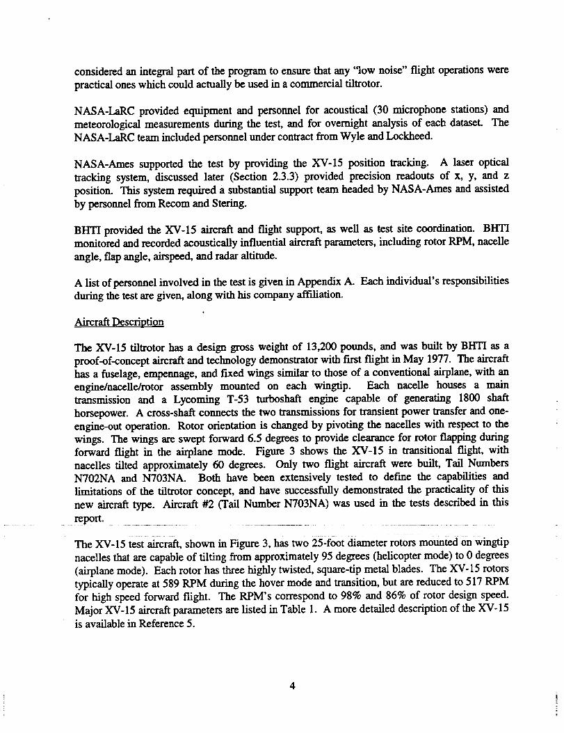
The XV-15 tiltrotor has a design gross weight of 13,200 pounds, and was built by BHTI as a
proof-of-concept aircraft and technology demonstrator with first flight in May 1977. The aircraft
has a fuselage, empennage, and fixed wings similar to those of a conventional airplane, with an
engine/nacelle/rotor assembly mounted on each wingtip. Each nacelle houses a main
transmission and a Lycoming T-53 turboshaft engine capable of generating 1800 shaft
horsepower. A cross-shaft connects the two transmissions for transient power transfer and one-
engine-out operation. Rotor orientation is changed by pivoting the nacelles with respect to the
wings. The wings are swept forward 6.5 degrees to provide clearance for rotor flapping during
forward flight in the airplane mode. Figure 3 shows the XV-15 in transitional flight, with
nacelles tilted approximately 60 degrees. Only two flight aircraft were built, Tail Numbers
N702NA and N703NA. Both have been extensively tested to define the capabilities and
limitations of the tiltrotor concept, and have successfully demonstrated the practicality of this
new aircraft type. Aircraft #2 (Tail Number N703NA) was used in the tests described in this
report.
The XV-15 test airc_, shown in Figure 3, has two 25-foot diameter rotors mounted on wingtip
nacelles that are capable of tilting from approximately 95 degrees (helicopter mode) to 0 degrees
(airplane mode). Each rotor has three highly twisted, square-tip metal blades. The XV-15 rotors
typically operate at 589 RPM during the hover mode and transition, but are reduced to 517 RPM
for high speed forward flight. The RPM's correspond to 98% and 86% of rotor design speed.
Major XV-15 aircraft parameters are listed in Table 1. A more detailed description of the XV-15
is available in Reference 5.
4
Figure 3. XV-15 Aircraft #2 (N703NA) Used in Noise Tests
TABLE 1. XV-15 TILTROTOR DESIGN AND OPERATING PARAMETERS
GROSS WEIGHT .............................................
PROPS/ROTORS (2)
NUMBER OF BLADES .......................
DIAMETER ..........................................
ROTATIONAL SPEED .......................
ROTATIONAL TIPSPEED ..................
ENGINES (2) ........................................
13,200 lb.
3
25 feet
601 RPM @ 100%
589 RPM @ 98% (HELICOPTER MODE)
517 RPM @ 86% (AIRPLANE MODE)
771 FEET PER SECOND @ 98%
677 FEET PER SECOND @ 86%
LYCOMING T53
The XV-15 flight envelope, shown in Figure 4, illustrates the combinations of nacelle angle and
airspeeds for stabilized flight. It should be noted that a fairly broad range of nacelle angles and
airspeeds is possible within this operating envelope. The acoustic effects of avoiding certain
portions of this envelope can guide flight operations of the XV-15 (and presumably other
tiltrotors) in minimizing external noise. The present test was designed to extend the body of
information available to define these effects.
5

100
8O
_D
60
Z,,qC
LU.,J-, 40UI
Z
2O
m_
XV-15 1995 SSC NOISE TESTNASA/BHTI
XV-15 STABILIZED FLIGHT ENVELOPE
1
\0 20 40 60 80 100 120 140 1(;0 180 200
CALIBRATED AIRSPEED, kts.
Figure 4. XV-15 Flight Envelope
2.3 TEST SETUP
The general layout of the test site is shown in Figure 5. The flight track was selected so the
microphone array would be in the flattest portion of the terrain, away from trees and easily
accessible by vehicle. NASA-LaRC acoustic recording equipment was housed in
instrumentation vans, with 10 microphone sites being supported by each van. A trailer was set
up south of the flight track to serve as control headquarters for the test. The optical tracker site,
north of the flight track and offset by about 4700 feet, was on a rise which commanded a view of
the entire flight track, allowing for early acquisition of the aircraft. A weather balloon was
deployed near the tracker site to acquire layered atmosphere data, and ground-based
meteorological data was recorded at the BHTI van and at one of the NASA vans. Aircraft
parameters were recorded onboard the XV-15.
6

IFLYOVER IW=ul_r Monitoring Station
• i
N llelil_l
N BttTI, NASAW *'--- --" E L-mm_mmion Wm
(Ni & W_l_- Dim)
S T_ Ik.dc_
Figure 5. XV-15 Noise Test Setup (Phase 1 Test)
All datasets were recorded in parallel with a satellite-synchronized time code signal. Prior to
each flight, the XV-15's onboard timeeode generator was synchronized with a satellite time code
unit at the BHTI Flight Test Center to provide time correlation between airborne and ground
based recordings. During the test, safety of flight data was telemetered from the XV-15 to the
ground station at the test site command post, where it was monitored continuously.
2.3.1 Acoustic Measurements
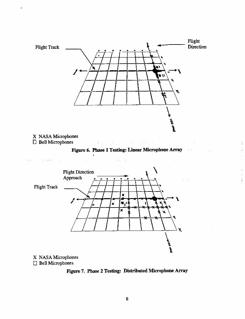
During "Phase 1" testing, noise was measured with microphones arranged as shown in Figure 6.
This is a fairly linear array oriented perpendicular to the flight track, and extending about 2300
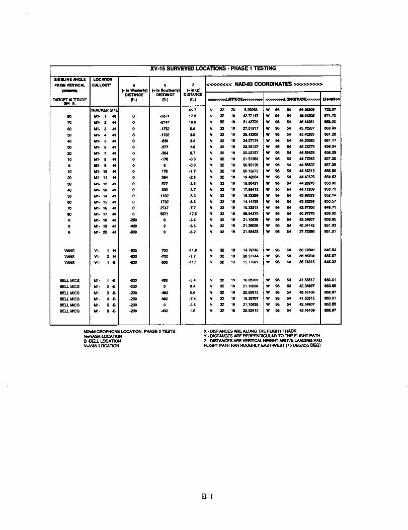
feet to each side. The exact positions are given in Appendix B. The purpose of this phase was to
provide data to support noise prediction efforts and to document tiltrotor sound characteristics at
specific points in the flight envelope. XV-15 flight conditions consisted of descents, level
flights, takeoffs, and hover.
In "Phase 2"' testing, the microphones were re-deployed over a large ground area near a simulated
"vertiport", as shown in Figure 7. The purpose was to define maximum and minimum noise
contours for civil vertiport land use planning. As in the initial Phase 1 testing, the flight
conditions consisted of descents, level flights, takeoffs, and hover.
7
Flight Track
XJi i f-i \'It \ I.,.'i __!,\ I,-<_"
/,'/il\
L
X NASA Microphones
[] Bell Microphones
Figure 6. Phase 1 Testing: Linear Microphone Array
FlightDirection
Flight Track
\Flight DirectionApproach _ I_ %
l 1o:/; l,,, °iL_.\_,"_,,\ 't,\\
X NASA Microphones
[] BellMicrophones
Figure 7. Phase 2 Testing: Distributed Microphone Array
8

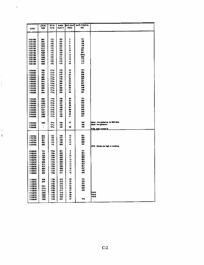
The sequence of testing, along with field notes made by the author, is listed in Appendix C.
2_3.2 Meteorological Measurements
Acoustic testing was generally conducted when weather conditions met the following criteria:
- average surface (10 meter above ground level) winds less than 10 knots
- relative humidity less than 95%
- no precipitation present
- visibility greater than 3 miles
- ceiling greater than 1500 feet.
Because of the low wind requirements,earlymorning flightswere scheduled. Based on weather
information availableat3:00 PM priorto each potentialtestday,plans for the next day's testing
were made.
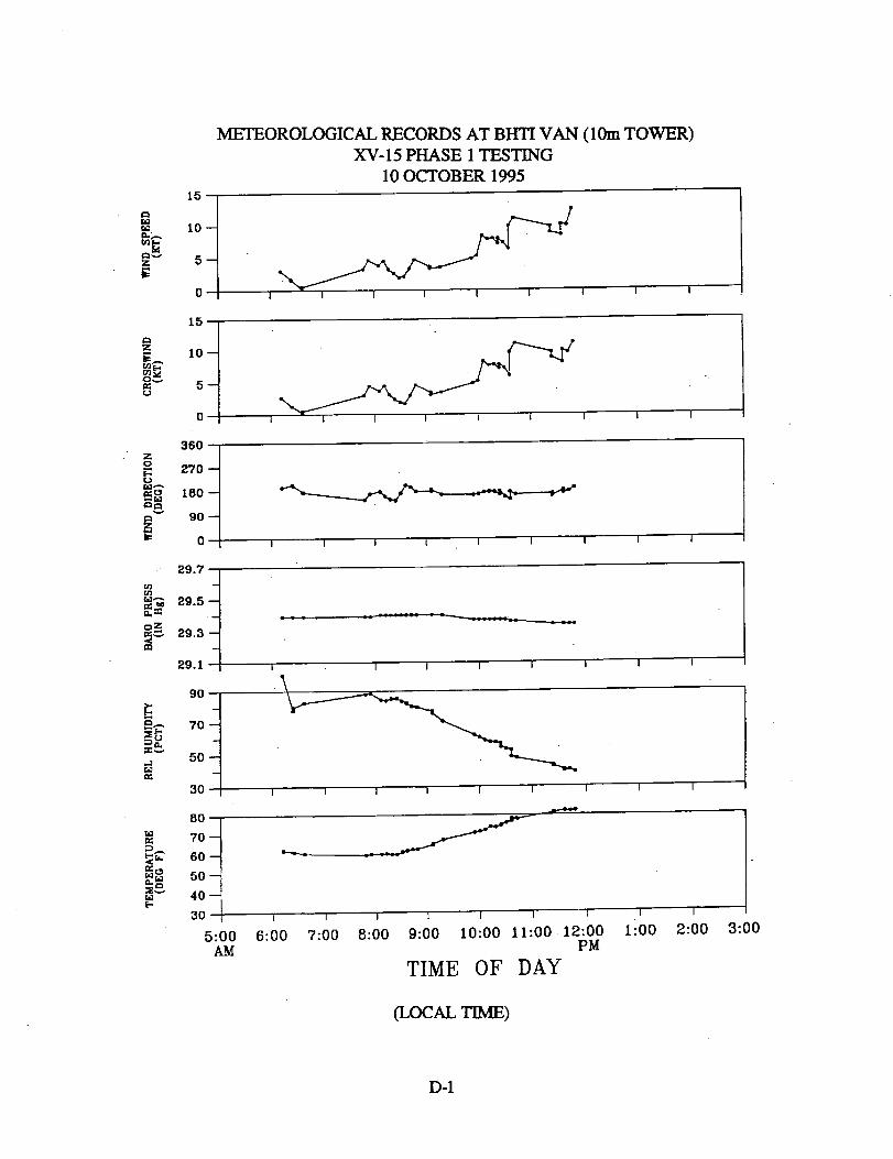
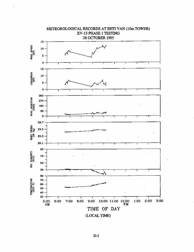
During testing, meteorological data was recorded at the BHTI acoustics van, where monitor
instrumentation was located on a 10-meter tower. These data are presented graphically in
Appendix D. In addition, NASA monitored meteorological conditions at a ground tower and
aloft on an airborne weather balloon positioned near the flight track. Figure 8 shows NASA's
ground tower.
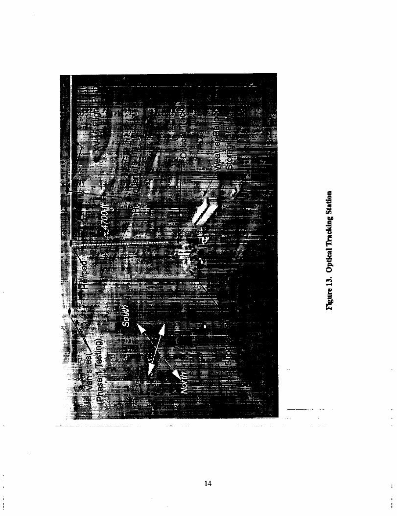
2.3.3 Position Tracking System
Aircraft position was monitored and recorded during the test by an optical tracking system
provided by NASA Ames. A photo of the tracker support vans is shown in Figure 9. This
system provided a continuous, real-time display of longitudinal (x), lateral (y), and vertical (z)
aircraft position to a display in the XV-15 (Figure 10) and to a monitor in the control trailer
(Figure 11). The tracker's ground station generates and directs a laser beam toward the aircraft,
where an aircraft-mounted retro-reflector reflects the beam back to the ground station. The retro-
reflector mounted on the XV-15 is shown in Figure I2. The ground station was stab'dized at a
known, pre-surveyed position with respect to the flight track, and the measured return time of the
beam, along with precise knowledge of the its azimuth and elevation, provided a very accurate
(+ 1 meter) measure of x,y, and z position at a sample rate of 10 per second. The ground station
was located approximately 4700 feet north of the flight track (see Figure 13).
To assist the pilot in setting up each pass, three 1000-watt lights were stationed along the track.
By aligning these lights, the pilot could enter each pass very accurately, so that only small
corrections were necessary when the tracker acquired the XV-15 and enabled the onboard
position indicator. One of these lights is shown in Figure 14.
9
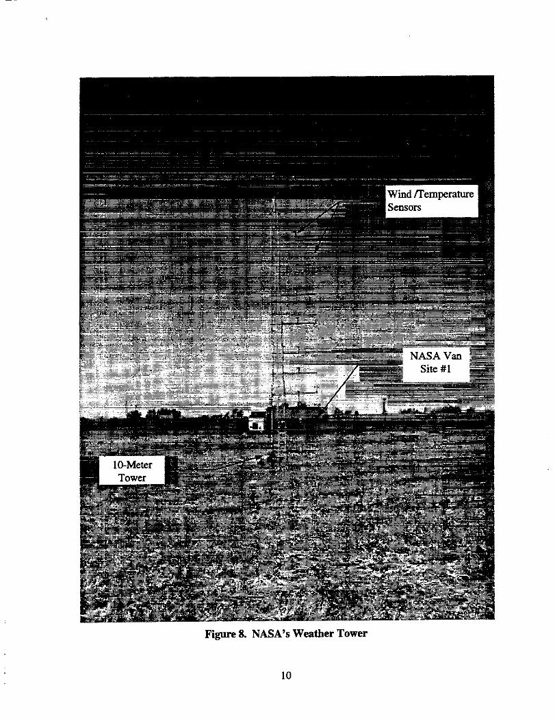
Figure 8. NASA's Weather Tower
10

a
C_
r_
11

[Position
]Display
Figure 10. XV-15 Cockpit
Aircraft PositionDisplay
BryanEdwards(BHTI)
Figure 11. Headquarters Trailer with Test Personnel
12

Figure 12. XV-15 Details
13
i
i
+C_
14

Figure 14. Flight Track Marker
15

2.3......44Aircraft Parameters
An onboard recording system monitored basic aircraft flight and operating parameters. These
were recorded in flight, then analyzed and permanently stored. Table 2 is a list of the flight data
recorded during these tests.
TABLE 2. FLIGHT DATA RECORDED DURING TESTS
DATA CODE ITEM CODE DESCRIPTION UNITS
00DV02 P342 BOOM ALTITtJDE FI
00DV04 D327 RADAR ALTIMETER FT
00QP01 D010 PITCH ATITrI._E DEG
00QP02 D008 ANGLE OF ATrACK DEG
00QQ01 D011 YAW ATITrUDE DEG
00QQ02 D007 ANGLE OF SIDE-SLIP DEG
00QR01 D009 ROLL ATHTUDE DEG
00VF03 P002 BOOM AIRSPEED KNOTS
00VV02 V086 RATE OF CLIMB FT/MIN
10DF04 DO21 F/A CYC STICK CONTROL POSN %
10DF05 DO24 RUDDER PEDALS CONTROL POSN %
10DF06 DO23 POWER LEVER CONTROL POSN %
10DL02 DO22 LAT CYC STICK CONTROL POSN %
12DM13 D617 FLAP POSITION DEG
25DM12 D161 #2 PYLON CONVERSION POSN DEG
25DM13 D186 #1 PYLON CONVERSION POSN DEG
30RM03 R106 ROTOR RPM (@ reduced sample rate) %
2.4 PHASE 1. "LINEAR" MICROPHONE ARRAY TESTING
Phase 1 testing was accomplished on 9 test days during 1995. October 10, 12, 16, 27, 28 andNovember 1,4,7, and 8.
The linear microphone array consisted of 17 microphones along a line perpendicular to the flight
track, and an additional 3 microphones along the flight track. The exact positions are given in
Appendix B. An aerial view of a portion of the linear array is shown in Figure 15.
2.4....._!1Flight Conditions
The XV-15 passed over the microphone array at constant airspeed/nacelle angle combinations
and constant flight angles. Test conditions consisted of level flights, descents, climbs, and hover
as defined in Appendix E. Prior to the test, each condition was assigned a priority classification
of 1, 2, or 3. The "priority 1" conditions were considered essential to the overall test objectives.
All the Priority 1 conditions was completed first, then the Priority 2 and 3 test conditions were
included as flight time permitted. The XV-15's landing gear was up during level flight and
during descents at airspeeds greater than 90 knots. During descents less than 90 knots, the
landing gear was down.
16

I
i
17
2.4.1.1 Level Flight (Phase 1 testing)
The flight profile for the Phase 1 level flights is sketched in Figure 16a. During each pass, the
XV-15 passed over the microphones at a specific altitude and flight condition. The level flight
airspeed/nacelle angle combinations tested are shown in Figure 16(b), and listed in Appendix E.
Each level flyover was initiated at a point approximately 2 nautical miles uprange of the line of
microphones. From this point, the desired flight condition was maintained while passing over
the line of microphones and continuing to a point approximately 1 nautical mile past the
microphones. After breakoff, the XV-15 continued in a "racetrack" pattern and set up for the
next pass.
2.4.1.2 Descents (Phase 1 testing)
The flight proflies for the Phase 1 descents are sketched in Figure 17a. Flight direction was from
East to West. During each pass, the XV-15 passed through a point 394 feet (120 meters) above
ground level, an altitude that corresponds to the descent condition currently used in helicopter
noise certification. The nacelle angle/airspeed combinations flown during descent are shown in
Figure 17b, and listed in Appendix E.
Each descent was initiated at a point about 2 nautical miles uprange of the line of microphones.
From this point, the desired flight conditions was maintained while passing over the microphones
and continuing as long as practical past them. Specific breakoff altitude was left to the pilot's
judgment. After breakoff, the XV-15 went around and set up for the another pass.
Descents received the heaviest emphasis during this test because of the strong influence this
condition has upon terminal area noise impact. .........
2.4.1.3 Takeoffs (Phase 1 testing) .............
The flight profiles for the Phase 1 takeoffs are sketched in Figure 18(a), patterned after the
helicopter noise certification procedure. Flight direction was from East to West. During each
pass, the climb was initiated at an uprange position intended to bring the X'V-15 through a point
394 feet (120 meters) above ground level. This altitude matches that used in the descent
conditions.
Each takeoff was entered by first flying level at 100 feet above ground level toward the line of
microphones, then initiating a climb at pre-determined uprange point based on the predicted
climb angle for that flight condition. From this climb initiation point, the desired flight condition
was maintained while passing over the line of microphones and continuing to a point
approximately 1 nautical mile downrange from the microphones. After breakoff, the XV-15
went around and set up for the next pass.
18

_a|mm|mmmmm|m||mm|m|(_lmmm|m||mmm|mm||m||
1500"
N
(a) Flight Path
:;; .;
Helipad
"D
u5,--,I
z
ILl
.J
UJ
Z
100
80
6O
4O
20
inlnlS
LEVEL FLIGHT
k
\
MICROPHONESETUP#1:LINEARARRAY
I11A#_ule AG L
• J
0 20 40 60
"l&
IP'
80 100 120 140
CALIBRATED AIRSPEED, kts.
160 180 200 220
Co) Flight Conditions
Figure 16. Phase 1 Level Flight
19

IAPPROACH I
XV-15 fl_ Ihrougha lx_nt 394'cemer
3 dog.4. ., " " "_ 394' @e
I_."6 _g_._'_ ,. ° o "9 deg._ "12 dc_.-
-"W E •
S
(a) Flight Paths
XV-15 Fiil_ Path
MICROPHONE SETUP #1: LINEAR ARRAY
¢=D
,,,,,J
7
<E
I,U,,_J,_JILl
0<E
Z
100
80
60
40
20
0
0 20
7 *,,L
I
!
L
40 60
e._t_l_N01_O Wr
XV-15 1995 SSC NOISE TESTNASA/BHTI
APPROACHi
11[" "; J'"
l
%
\
80 100 120
CALIBRATED AIRSPEED, kts.
140
,J_ $ DEGREE GLIDESLOPE
O 6 DEGREE GLtDESLOPE
_,, IPDEGREE @LIDESLOPE
12 DEGREE GLIDESLOPE
J
\\ i
160 180
(b) Flight Conditions
Figure 17. Phase 1 Approaches
2OO
20

[TAKEOFF[
N
XV-15 flies througha point 394' above
_'_' _
ee
Microphone
S •(a) Flight Path
6_o
'ID
uS-J
¢.9Z
UJ._l-JUJ
¢D
,<
Z
100
8O
6O
4O
2O
TAKEOFF
J J j,,JMICROPHONE SETUP #1: LINEAR ARRAY
l
0 20 40 60
\
80 100 120 141
\\
I 1 I [
CERTIFICATION _FAKEOFFS" • ' rv I
-j
' I
160 180 200
CALIBRATED AIRSPEED, kts,
(Flight Conditions)
Figure 18. Phase 1 Takeoffs
21

2.4.1.4 Hover (Phase I testing)
The XV-15 hovered over the center microphone at an altitude of 394 feet, slowly changing
azimuth while maintaining a stationary position. The original intent was to hover at 15 degree
incremental headings while taking acoustic data. At this altitude, however, the pilot had no
visual landmarks, and station-keeping was a problem for long-duration hovers. For this reason, a
brief, continuous-turn hover was performed.
2.4._...22Meteorological Conditio_ - Phase 1 Testing
The meteorological conditions during each Phase 1 test day, as measured at BHTI's 10-meter
tower, are presented graphically in Appendix D, pages 1-9.
The meteorological conditions measured at altitude and at NASA's ground station are not
included in this report. These are part of the database acquired and processed by NASA.
2.4.3 XV-15 Position/Airc_ Parameters
Position data and aircraft state data are not included in this report. These have been incorporated
in the database processed by NASA in parallel with the noise data for each of the twenty Phase 1
microphone positions.
2.5 PHASE 2. "DISTRIBUTED" MICROPHONE ARRAY TESTING
After completion of the Phase 1 testing, the microphones were re-deployed into the distributed
array previously shown in Figure 7. Phase 2 testing was accomplished on 3 test days. November
13, 15 and 16.
The distributed microphone array consisted of 30 microphones covering an area 2000 feet
laterally from the flight track, and 7000 feet (-6000 to +1000) along the flight track, as previously
shown in Figure 7. The exact measurement positions are given in Appendix B.
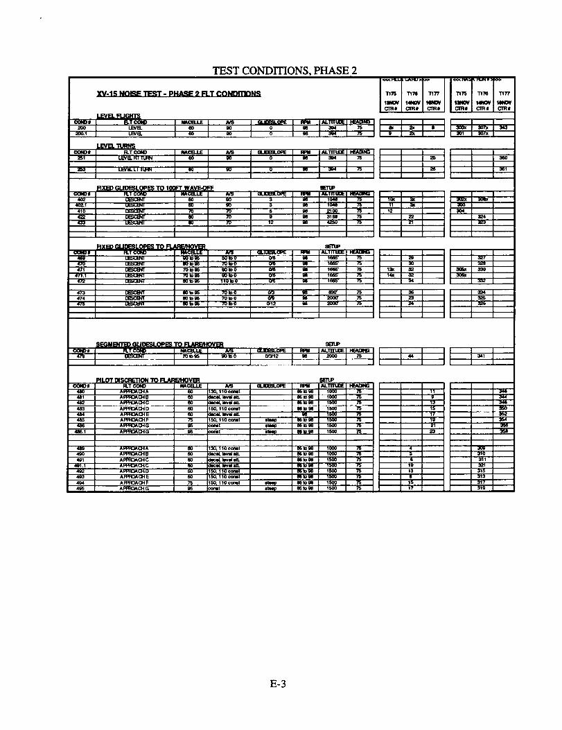
2.5.1 Flieht Conditions
During Phase 2 testing the XV-15 test conditions included level flights, descents to IGE hover,
takeoffs from IGE hover, and flight idle. Details of each flight condition flown are given in
Appendix E.
2.5.1.1 Level Flights (Phase 2 Testing)
A limited number of level flights were performed during Phase 2. These consisted of the
"housekeeping" pass conducted each test day to allow tracing of day-to-day test condition
variations, and a right and a left level turn over the array. A total of 4 level flight conditions were
flown.
22

2.5.1.2 Descents (Phase 2 Testing)
For descents, the XV-15 approached the helipad from the West along a heading of approximately
75 degrees, guided by the optical tracker signal displayed in the cockpit. The approaches were
categorized according to their glideslopes. A total of 22 descent conditions were flown during
Phase 2.
Fixed Glideslopes to 100 ft Waveoff. These descents were performed in a manner similar to
those in Phase 1 testing. The intent was to provide "'large-array" data that could be correlated
with noise predictions based on the Phase 1 results. During each pass, the X'V-15 maintained a
fixed glideslope and flight condition while attempting to fly through a point 396 above the
helipad. After passing over the pad, the condition was held until a point about 100 feet above the
ground, where the XV-15 broke off and climbed out in preparation for the next pass.
Fixed Glideslopes to Flare/Hover
During each of these descents, the XV-15 initially maintained a fixed glideslope and flight
condition, but it was necessary to bring the nacelles to the full helicopter mode and flare to an
IGE hover over the helipad. The point at which the constant flight condition was discontinued
was at the discretion of the pilot, and was of course dependent on the target descent angle and
airspeed.
Segmented Glideslopes to Flare/HoverThis descent was similar to those discussed in the previous paragraph, but included two
glideslope segments. The initial segment required a 3 degree glideslope, and the second segment
required a 12 degree slope. As in the fixed glideslope tests, the XV-15 maintained a constant
flight condition as long as practical, then flared to a hover over the helipad. Only one of these
segmented approaches was included in this test.
Pilot Discretion to Flare/Hover
During this series of tests, the pilot was constrained only by the requirement to maintain the
desired flight track and to approach to a hover over the helipad. The pilot, Roy Hopkins, selected
a series of practical approaches which might produce a broad range of noise contours. These
were labeled A through G in the test log. This series of approaches was run November 14, and
was repeated November 16.
2.5.1.3 Takeoffs (Phase 2 Testing)
For takeoff, the XV-15 hovered over the helipad, then climbed out to the West along a heading of
approximately 255 degrees, guided by the optical tracker signal displayed in the cockpit. Except
for the requirement to maintain flight track, the takeoff flight parameters were not constrained,
but were left to the discretion of the pilot. These were labeled Takeoff "A" through "Q" in the
test log.
23

2.5.1.4 IGE Hover (Phase 2 Testing)
An IGE hover was performed at an approximate wheel height of 15 feet over the helipad as
previously shown in the photograph of Figure 2. Measurements were taken at four aircraft
headings. Two headings were aligned with the flight track (75 and 255 degrees) and two more
were perpendicular to the track (165 and 345 degrees).
2.5.1.5 Flight Idle (Phase 2 Testing)
A brief set of acoustic data was acquired with the XV-15 at flight idle, i.e., the rotors were at flat
pitch and turning at approximately 98% RPM. The XV-15 was positioned at the center of the
helipad. Two headings (75 and 255 degrees) were included.
2.5.2 Meteoroloeical Conditions
The meteorological conditions during each Phase 2 test day as measured at BHTI's 10-meter
tower are presented graphically in Appendix D, pages 10-12.
2.5.3 XV-l_.._.55Position/Aircraft Parameters
Position data and aircraft state data are not included in this report. These have been incorporated
in the database processed by NASA in parallel with the noise data for each of the thirty Phase 2
microphone positions. During the final test day, November 16, the optical tracker was not
available, so tracking data was acquired using an experimental Differential Global Positioning
System (DGPS) installed on the XV-15.
24

3-- RESULTS/CONCLUDING REMARK S
The acoustic results are not included in this report, and no conclusions are drawn as to the
optimal operating modes of the XV-15. NASA-Langley is processing and correlating the
acoustic, position, aircraft state, and meteorological datasets for Phase 1 and Phase 2 testing.These will be made available to authorized users.
An experimental means of viewing the Phase 2 test results using computer graphics has been
developed under the current contract. This display, called the Large Array Noise Data Display
(LANDD), simultaneously displays aircraft position, noise data at 30 microphone locations, and
limited aircraft state data (heading, roll, pitch, yaw, nacelle position) on a computer screen.
Computer interpolation of the noise data allows instantaneous color contours of the time-varying
noise to also be displayed. A sample of the on-screen display is shown in Figure 19. This
simultaneous viewing of flight path, noise, and aircraft state, provides a tool for visually isolating
those flight parameters which most influence total noise.
The LANDD employs the NASA-developed Flow Analysis Software Toolkit (FAST), and was
developed on a Silicon Graphics Indigo 2 platform. Currently, 11 approaches and 1 takeoff
condition are loaded and available for display. It is recommended that additional Phase 2
approaches and takeoffs be incorporated into LANDD so that comparative studies can be
completed.
25

L_
0Z
m
o_
ill
Z
_D
L.
T-
_=_
oJr
°_
26
REFERENCES
° Riley, R.,Brieger, J.,and Maisel, M, "Preliminary Investigation into XV-15 Tiltrotor
Acoustic and Directivity Characteristics," BHTI Report 699-099-288, November 1988.
° Brieger, J., Maisel, M., and Gerdes, R. "External Noise Evaluation of the XV-15
Tiltrotor Aircraft," presented at the American Helicopter Society National Specialists'
Meeting on Aerodynamics and Aeroaeoustics, Arlington, Texas, February 1987.
° George, A. R., Smith, C. A., Maisel, M. D., and Brieger, J. T., "Tiltrotor Aircraft
Aeroacoustics," presented at the 45th Annual National Forum of the American Helicopter
Society, May 1989.
. Edwards, Bryan D,"Extemal Noise of the XV-15 Tiltrotor Aircraft," NASA Contractor
Report 187463, May 1991.
. Maisel, M. D., "XV-15 Tiltrotor Aircraft Research Aircraft Familiarization Document,"
NASA TMX-62A07, January 1975.
27


APPENDIX A
LIST OF TEST PERSONNEL


TEAM
XV-1R NOI_E TEST PERSONNELOct..Nov. 1905 @ SSC, Waxahachie, Texas
ASSOCIATION NAME INDIVIDUAL RESPONSIBILmES
lUlSAd.IRC ACO4US'nCS
NASA-LIRC ACOqSTICS
_.SA-LIRC ACOUSTICS
NASA-t.iRC ACOUS'I_S
K_SA-LIRC ACOUSTICS
, It_SA4.aFIC ACOUS'ncs
NASA-LaRC ACOUST',CS
NASAl.aRC ACOU_ICS
NASAl.aRC ACOUSTICS
NASA-_RC ACOUSllCS
NASAd_RC ACOUSllCS
NASA-LaRC ACOUSTICS
NASA-LIRC ACOUSllCS
NASA-LaRC ACOUSllCS
BELL _k(:OtJm'_S
BS.L ACO.IST1CS
B_L ACOUSTICS
BilL ACOUS'ncs
IF.LL Fumcr
BE.L RJOl-n"
BE.L FUGHT
BB.L FUGHT
FLIGHT
BS.L RJGHT
8ELL FUGHT
_LL RJGHT
BELL RJGHT
BB.L_
8B.L FUGHT
8B.L FUGHT
BIS.L FUGHT
BB.L FUGHT
BELL FLIGHT
BELL RJGHT
NAS_ AIIES LAS_ TIRACI_.R
Nk3A- AMISSLASER TRACKER
NkSA- .4MES I.J_ _
NASA- AMES L,_SER TRAC:K]ER
N,_SA-AMES L.ASERT_
MICHAEL
N/_SA-LIRC JOHN
NkSA.4.aRC
NASA4.aRC OO¢.YN
LOC_.D C_Ud_L_ (K_
NASA-LmC OAV1D (0.¢.)
_EF.D MARK
WYI.E I.ABS TOM
WYLE LABS NICHOLAS
WYLE LABS VlRGILIO
WYLE I.ASS KEITN
WYLE LASS JOHN
NkSA-LaRC JAYE
BELL I_YM4
BELL JOHN
8E.L RICK
8B.L
BELL COLBY
ROY
DON
BILL
BE.L JERRY
BELL ALAN
BB.L JERRY
BB.L JIM
BELL MIKE
BB.L MARK
IOB.LY
BELL I0_
BELL HARRY
BB.L FRED
K]_
B_LL WE]DON
NASA-AMES FRED
RECOM rn
RECOM ,NM
RECO_ RICK
STERING PAM
CONNER
IINtCOLINI
LYLE
SANTA MARIA
RUTLEDGE
OAV?S
WLSON
BAXTER
KARANGB.Bq
SCUDOER
SWNN
EIW/NmS
m:UEGER
RILEY
COX
NICKS
HOPKINS
BORG
Mkq'rlN
RCKARD
ADAMSON
WALKER
WILSON
SHAW
S'TOUFFLET
SPNEY
COGDILL
OURAND
MAJOR
MITCHELL
SHGE]BOTO
FARR
LAWRENCE
TAYLOR
PFOHI_
PROJECT BqGIIIEER
PROJECT ENC4NEER
I_IGINEBR
INTERNAL NOISE
TEST E_IGINE_R
I_SA- LaRC DATA ANALYSIS
_ATION
_ DATA ANALYSIS
NASA _AI'ION
INSI"RUM_ATION
INSTRUMe_ATION
NASA INSTRUMB_ATION
NASA INSTRtJM_ATION
MErEOFtOLOGICAL _ALLOON) _STRtAIB_rI'ATION
PROJEClr E]_JNEER -ACOUSTICS
Aoous'ncs
N:OUSTlCS
RRO,ECl" ENGB4E]ER- FLISI.R
PILOT
PILOT
FUGHT TEST
.OGISTtCS
INSTRUMENTAllON
INS'TRUkEh'lrATION
)ATA OPERATIONS
DATAOPI_tATIONS
DATAOPERATIONS
RJ(31.fr
FUGHT
RJGHT
RIGHT
L.J_qr;RTRA_
LASER"/'RACtaER
TRACKER
TRACKER
A-1


APPENDIX B
MICROPHONE POSITIONS - SURVEYED POINTS

XV-15 SURVEYED LOCATIONS - PHASE 1 TESTING
_DBLINE ANGLE
FROM VER'nc/L
TARGET ALTI'RJDE394 ft.
8O
7O
60
5O
4O
3O
2O
10
0
10
2O
3O
4O
5O
6O
7O
8O
0
0
0
VANS
VANS
VANS
BELL MICS
BELL MICS
BELL MICS
BELL MICS
BELL MICS
BELL MICS
(+ is Wlamty)
DISTANCE
LOC_IION
C_LLOU'P
_)
macron S_T_
M1- I -N 0
MI- 2 -N 0
M1- 3 -IM 0
M1- 4 -N 0
M1- 5 -N 0
MI- 6 -N 0
M1- 7 -N 0
MI- 8 -N 0
M1- 9 ..IN 0
M1- 10 -N 0
M1- 11 -N 0
MI- 12 -N 0
MI- 13 -N 0
M1- 14 -N 0
M1- 15 -N 0
M1- 16 -N 0
M1- 17 -N 0
MI- 18 -N -200
M1- 19 -N -40O
M1-2O -N -500
y Z
(÷ Is So-me_/) (÷ is tin)DISTANCE DISTANCE
(ft.) (ft.) <<<<<<<_ O E>>>>>>:,_>
65.7 N 32 20 6.2gL_5
•5671 17.3 N 32 19 42.'r2147
-2747 10.8 N 32 19 31.43729
-173Q 6.6 N 32 19 27.51817
-1192 3.9 N 32 19 25.43206
3.8 N 32 19 24.07174
-577 1.6 N 32 19 23.06127
-364 0.7 N 32 19 22.23"r97
-176 -4).0 N 32 19 21.51365
@ -0.0 N 32 19 20.83135
176 -1.7 N 32 19 20.15273
364 -2.8 N 32 19 19.42834
577 -3.5 N 32 19 18.60421
839 -3.7 N 32 19 17.59412
1192 -5.3 N 32 19 16.23299
1732 -6.8 N 32 19 14,147_G
2747 -7.7 N 32 19 10.22915
5671 -17.5 N 32 18 58.94370
0 -3.6 N 32 19 21.10635
0 -5.5 N 32 19 21._0Q9
0 -6.2 N 32 19 21.65423
700 -11.9 N 32 19 14.'/1)740
-700 -1.7 N 32 19 28.51144
(500 -11.1 N 32 19 15.771_1
492 .3.4 N 32 19 16.2m'07
0 0.4 N 32 19 21.10635
-492 5.6 N 32 19 25.g2o15
482 -7.4 N 32 19 16.28707
0 -3.6 N 32 19 21.106_5
1.6 N 32 19 25.g_615
V1- 1 -N -5(X)
V1- 2 -IN
Vl- 1 -8 -500
M1- 1 -8 -200
M1- 2 -8 -200
MI- 3 -8 -200
M'I- 4 -8 -200
M1- 5 -8 -200
M1- 6 -8 -2OO
<<<<<<<< NAD-83COORDINATES>>>>>>>>>
<<<<<<<<<LONGII"J DE>>>>>>: Bevlltlon
W 2O 54 54.36509 723.07
W 96 54 41L342(_ 674.70
W 96 54 46.44281 688.20
W g6 54 45.711287 663.99
W 96 54 45.43285 861.28
W 96 54 ,ll5.2o282 861.17
W 96 54 45.0_278 651).04
W 96 54 44.m429 658.O9
W 96 54 44.T/2,13 657.35
W 96 54 44.(B822 857.39
W 96 54 44.54313 655.66
W 96 54 44.42129 654.63
W 96 54 44.28276 65o.g0
W 96 54 44.11289 653.70
W 96 54 43.M329 652.14
W 96 54 43.53254) 650.57
W 96 54 42.87306 640.71
w M s4 4o.m 6,_._
w 96 54 42.34837 853.85
w 96 54 40.04142 851.93
w 96 54 37._ 651.21
w 96 54 36.5"/119o 645.54
w 96 54 38.88704 855.67
w 96 54 36.74315 646.32
w 96 54 41.53812 650.01
w 96 54 42.34937 ¢S3. IB
W 96 54 43.161(1e 658.97
W 96 54 41 °53812 650.01
W 96 54 42.34837 653.85
w g6 $4 43.16100 658.97
M2=-MICROPHONE LOCA'rlON, PHASE 2 TESTSN-:NASA LOCATION
B,=BELL LOCATIONV=VAN LOCATION
X - DISTANCES ARE ALONG THE FLIGHT "I'RACKY - DISTANCES ARE PERPENDICULAR TO THE _ PATHZ - DISTANCES ARE VERTICAL HE]GIfT ABOVE LANDING PAD
PATH RAN ROUGHLY EAST-WEST (75 DC--C-#255DEG)
B-!

ON.LOUT"
WEA_ BALLOON 130
OPIIC_, TRAC_0_ 11m
I-_.PAO _ ;T.) Ul- g -N 0
MIG_0PHO_ I_- _ -N
MICROF_DNE I_- :3 -N
IaCROPHONE I_- S *N
IaCROI_-OE 142- ? -N 30OO
MICROPHOI_ I_- 8 -N S000
MICROPHOIE M2- 9 -N _I000
MCFK)FHOI_ I_-10 -N 3OOO
M2-1 -N _0
MICROPHONE M2-12 -N 22_
MICROPHONE M2- 13 -N 1500
M2- 14 -N 1500
_E k_- 1$ .N lS00
M2- t4 44 1000
M2- 17 ,N 1000
k_- 18-N E00
M2- 19 -N 500
M[O:IOR4ONE M2- _-N 5OO
MK:ROPH0_E M2- 21 -N I 0I
MICROPHONE I_- 22-NI 0
M2- :D -N 0
MICROPHONE &G- 25 -N -800
MICROPHONE M2- :RS -N -600
MICROPHONE I_- _ -N -too
MICROPt'IOIE 142- Sm -N -1000
MICROPHONE M2- 2g -N -1000
IACROPHO_ M2- _0 -N .laOO
14X:_X:)PHONE M2- 1-61 37SO
MICAORI,IOI_ M2o 2-8
MIC_OPI_NE 142- 3-8
MICROPHONE i_ 4-B
M2- $.B S'FaO
IaCROPHONE M2- 6-8 STS0
MICROPt401_ M2- I-B
WEA'11"ER STA. V2- 1 -E _S00
XV*15 SURVEYED LOCATIONS - PHASE 2 TESTING
• I' z ¢<<<<<<< _ COORDINATES >>>>>>>>>
(+_- (.b (+ kup)
(_.7 N 32 29 6.292E5 W 96 54 54.,IM_e ?_.07
TEO 65.7 N 32 20 6.29266 W M 64 54.3&50g 72_07
0 0.0 N 32 lg 20.83136 W M _4 44.(_822 (Ib'/'.,,._
WI_THER BN.LOON
0PI"IC, AL _
MI-e,.N
0 _0
0 -6.8
T30 0¢0
0 122
5OO 8.O
IIW_ t0 "4
0 12.8
500 4.1
1000 3.7
lS00 S.5
0 4.1
1000 -5.11
0 4.9
1000
2OOO -0.S
0 9.0
1000 -2.7
0 7.6
1000 -1.0
2O00 0.4
t000 -7.7
lS_0 -e.0
0 .42
5OO 41.9
1000
1S00 -14.2
0 .41.5
500 -12.0
10_) -15.3
N _ Tg 12,_2S3 W ¢6 SS S3.g070S _I_._Z
N 32 lg 14.38412 W M $5 _.g_'l 8_iO.eO
N 32 lg 15.5SB45 W 116 $5 2g.0e195 M_,WI
N 32 19 10,(18187 W M Ix 28.2MG7 MSAI2
N 32 lg 3,3148G W M $5 27.0_O7 M7.Sg
N 32 lg 16+72430 W 96 r_ lg.29244 670,19
N 32 19 1t JI_SB0 W M ,_ 1&,1_'75 M4.._
N 32 19 6.g_7 W M M 17.63186 ¢111.1
N 32 lg 4._ W 96 _ 17.,_N)40 MP..84
N 32 lg _T,?S_8_ W M; $5 10.162680 461.5
N 32 19 7.gGS01 W M $5 8.97678 661.63
N 32 19 1L_ W 9(; _ 1.97097 M4.31
N 32 19 8.M24_ W 96 $5 0.32140 (i$1.1
N 32 18 r_,187M W M $4 M6?IM
N 32 lg 19.M_3g W 9G $4 M+1N45
N _Q lg 9._M_6 W g6 $4 _4.r_om 684.74
N 32 19 20.14842 W 96 $4 50+42_28 M4M
N -'_ Ig 10_ W M $4 48.71_10 eM.3g
N 32 Ig 0._E_TG W gG $4 47.1:3017 _-7.'/7
N .t_ fl_ 15.g_471 W M $4 43.83:_4 45'/.8
N 32 111 11._ W 96 S4 43.00EI30 (141_.73
N _Q 19 (L13_41 W M 64 ,t2. t 847"1 (r_1..41
N 3Q 19 21.5t88 W M $4 38.88731 IB1.1
N 32 19 le.e"l g_2 W M $4 :_0_08 147.$4
N 32 19 11._J17 W M $4 S_.23780 648.29
N 32 19 6.E_4 W M $4 _8.4144g 643.1¢1;
N 32 19 22.20_00 W M S4 _B.1161 641,Bg
N 32 19 17_ W g6 S,I 32-29136 84_'m
N 32 19 12.40G82 W 9_ S4 31.4_1i3 (142.08
i_-f-N
_-2-N
M2..4..N
M2-S.N
k_.4-N
M2-7-N
M2-e-N
M2-e-N
M2-1_-N
M2-11-
M2-124q
M2-13-N
k_14-N
M2-1S-N
M2-1(kN
142-174'4
M2-11k'_
I_Q-I_,-N
M2-22,,N
M2-23.N
MZ-,_I-N
M2.-,ZS._
M2-2&N
M2-2?-N
M2-29-N
M2.30-N
0
4_2
.492
0
M3
1
22.0 N 32 19 20.51586 W M S8 26.75024 6"/3.43
17,3 N 32 19 1S._ W M _ 27+g_1881 670.74
132 N 32 19 10.876"/7 W 96 S8 27.12704 e_.(D
18.0 N 32 lg 20.51S_ W M SS 2L75_4 675.43
13.3 N 32 19 15._ W M _ 27.g_lg1 670.74
9.2 N 32 lg 10.8/677 W 96 $S 27.12704 MLID
3.4 N 32 lg 2.$6470 W SIS S8 4._ (M_.80
11. N 32 lg 9.441S8 W gG S6 20.50010 (14_JlO
M2-t.8
M2-2.8
M2-,_.8
M2..4-B
M2-S-B
M24.8
M2-7-B
I_-e_
800 8,6 N 32 19 8.20258 W 95 S8 23.7".jl319 _M.01 V2-'I+
k12. _ LOC_TI_. PHASE 2 11_
N= N_gA LOCATION
9- 8ELL LOCAI'IO_
"4- VAN LOCA'rK_
X- D_I"ANCES ARE ALONG THE R.IGI.fr I'lqACK
Z- OISTANC4ES ARE VERT1CAL _ ABOVE _ PAD
R,JGHT PATH RAN ROUGHLY EAST.WEST {7S DEG/2SS OEG)
]3-2

APPENDIX C
TEST SEQUENCE


DA'_
10/10/9510/10/9510/10/9510/1(Y9510/10/9510/10/9510/1Q/9510/1(1_510110/9510/IGR)5
1_1G'9510/10/951G'1G'951(Y1(Yg5I(Y1_95I(Y10/951G'10nl5l(Y1G_51Gr1(_5IKY10/S510/10/95
10/12_510/12/9510/12/951Qt12_1510/12/9610/12_951(Yl;_9510/12/9510/12/9510/12/S5
10/13/9510/13/9510/13/9510/13/95
10/16/9510/16/9510/16/9'510/16/95
1G'lE/9510/16/9510/16/9510/16/951Gr18/95
1Gr27/951(Y27/95I(Y2719G1_V27/'3G10/27'9510/27/9510/'27n)510/27/9510/27/95
I0r'27/9510,'27/9510/27/95,10/27/9510/27/_510/27/95I0r27/9510/27/951(Y27/gG
10/28/9510/28/95t0/28/9510/28/9510/28/9510(28/95
TEST SEQUENCE / TEST ENGINEER'S FIELD NOTES
LOCAL :_-15 NASA 3PIT1SHIF BH_ COND'N.
TIME FLT# RUN # REC_ NO.
749 161 101 6 101756 161 104 9 I(_A802 161 10Q 10 1r_8(_ 161 103 11 103815 161 106 12 104821 161 106 13 105829 161 107 14 106835 161 106 15 101640 161 109 16 107845 161 110 17 306
956 161 111 29 3061006 161 112 21 3051012 161 113 22 1(_1016 161 114 23 1091(_0 161 115 24 1091024 161 116 25 1101(_/' 161 117 26 1111032 161 118 27 1121038 161 119 28 1131041 161 120 29 1131047 161 121 101
746 162 122 8 101752 162 123 9 106756 162 124 10 1USA801 162 12S 11 304813 162 128 12 301818 182 127 13 302823 162 128 14 303829 162 129 1S 31583_ 162 130 16 31484,5 162 131 17 311
1631350 1631406 163 132 6 1011413 163 133 0 312
745 x750 164 101
164 - * 101758 164 134 9 101806 164 135 10 312814 164 136 11 313
164 137 12 310828 164 138 13 307a834 164 139 14 3068_ 164 140 15 309
758 1684 141 8 101802 l(la 142 9 324805 1684 143 10812 1684 144 11 324824 1684 145 12 325836 168a 146 13 326844 168a 147 14 327851 168a 148 15 323857 168a 149 16 320
1000 168b 150 21 1011006 I tlNJD 151 22 3211014 168b 152 23 319laQ1 138b 153 24 3161GO6 168b 154 25 3171031 168b 155 26 3181039 168_ 27
168b1049 158b 156 28 334
852 1(;9 157 2 1019O2 169 158 3 3349O6 169 159 4 334914 169 160 5 335919 169 161 6 335930 169 162 7 336
question on tracldng$1ow¢ond_ |o chock ti_IcMngnc_no k_ _"ve_c_l gm_ance dev_'Ino"
r_inQpter interferes - clmle XV-15, then c_ne In
_eo _ng a/c at ond ol mco_RI_ - fuel
],acm. sel on wong back - XV-15 ckcled, then goodrme vJn0_ oveme_z_'L..x',/-lS ton high (100')
•tmck_ _po_. - p_n _o_ gond!f'md q _IdUtude Off - _ mics oved_l¢led
kbodRI_ • fuellined up v;th lights, pilot Indicalo* sho_ r_h_ of conrseBe4 talcs ov_Quielest pess so fa_
Plint:'Nese hi_ attitude - bed - unrmturaJcoOl, ion"
B_ m_-3. xv.15 got vet,/ Iowto gnxmdBVI rating. 4. Trz_or on Boz Rd. - XV-15 ckcled, the_ set up for f_s pes_S'_ r_=2: PZot: '_d vZbs& hond_ _Wa_"7:30 fit sc_ but postl_med for fuel cot4amiml_on
Pilot: "T_Atm_ted run
Abort - Honsekee1_ng runHousek_p_9 - stiUsome questine on tracW, gmn r_g-1mn n_p3mn n_3
B_ ._,_.2
House_ept_. no traclt_ Inlo.
BVI mkq_4; m'_t fo_ 90 deg n_celie, got 80¢k_ by mistake
BVI ratrng-2: track_g ¢¢_estlon;lS-kl head,_nd., slowpau_ tmcidng CF,,,Ntio_eady; Pilot: "¢(xnfortable N_roach"
ZP_qmk_4er_qr_e94er_rm_Ft'rB-fu_
_use*_ep_g pcV_B_ ruing-2: h_h ¢n£. w_- nose north of trackBY1mk_=4_/_ "c_'t see gro,rxl - n_e h_"
_,q raU_-3_over. Nose @ 2SS ¢_g - checld_ track_ng_ov*r. Nose @ 2S5 de0
C-1
LOCAL XV-15 NASA BH'n SHIP Bl,f11 COND'N.
DATE lIME FLT# RUN • RECI NO.
11/01/95 955 170 163 5 101
11/01/95 g59 170 164 5 108
11/01/95 1004 170 165 7 108
11/01/95 1009 170 166 5 109
11/01/95 1015 170 167 0 334
11/01/95 1_2 170 168 10 501
11/01/95 1028 170 169 11 501
11/01/95 1033 170 170 12 501a
11/01/95 1039 170 171 13 502
11/01J_5 1043 170 172 14 115
11/01/95 1050 170 173 15 116
11/01/95 1066 170 174 16 117
11/04/95 73S 171a 175 18 101
11/04/95 743 171a 176 19 334
11/04/95 752 171a 177 20 3_
11/04/95 800 1'71a 178 21 336
11/04/05 806 171a 17g 22 337
11/04/95 816 1711 180 23 307
11/04/95 823 1Till 180 24 307
11/04)g5 830 1TII 181 25 306
11_ 836 171t 182 28 108
11/04/95 841 1718 183 27 108
11/04/_ 846 17111 184 28 501
11/04/95 955 171b 185 33 101
!1/04/315 1000 1TIb 186 34 502
11/04/95 1006 171b 187 35 344
1t/04/95 1012 171b 188 35 345
!1/04/95 1017 171b 199 37 342
11/04/95 10_1 171b 190 38 342
11/04/95 1027 1TIb 191 38 343
11/04/95 1033 1TIb lSI_ 40 340
11/04/95 1038 171b lSl_ 41 341
11_ 1235 171c 194 47 194
11/04/_ 171C 195 195
11/04/95 171C 195 48 195
11/07/95 806 172 196 10
11/07/95 815 172 197 11
11/07/95 821 172 198 12
11_7/95 832 172 199 13
11/07/95 840 172 200 14
11/0En_ 731 173l 201
11/0_/_ 738 1731 202
11/G_96 746 173a 203
11/08/95 753 173a 204
11/0e/95 759 173a 205
11/0_95 B06 173e 206
11/0_95 514 173a 207
11/_,_5 819 1738 206
11/08/95 _t5 173a 209
11/0_195 832 173a 210
11/0E_5 838 173a 211
11/06/95 938 173b 212
11/0e/95 947 173b 213
11/0e/95 1731) 214
11/06/95 1001 173b 215
11/018/95 1010 173b 216
11/08/95 1015 173_ 217
11106/95 1_ 173b 210
11/06/95 1032 173b 219
11/06/95 10_ 173b 220
11/06/95 104,2 1731) 221
331
333
328
101
8 101
9 354
10 355
11 356
12 352
13 353
14 350
15 351
16 347
17 348
18 348
22 101
23 332
24 331
25 330
26 33O
27 333
28
29
30
31 318
/U_ort - NO guldmce, no Bd data
Abort- No gulclance
R.._ R_II m_ed In
R'rB - Winds t¢_ Mgh to co_kme
_ove(
_ove(
C-2

't'_Al. XV-15 NASA _ SHIF BH'n COND_N.
DAnE lIME FL'r# RUN I REC# NO.
11/13/95 825 175 300 8 200
11113/95 835 175 301 9 200
11113/95 845 175 30Q 10 402
11/13/95 853 175 303 11 402
11/131'95 175 304 12 410
11113/95 175 305 13 471
11113,/95 920 175 306 14 471
11114/95 8_5 176a 307 2 200
11/14/95 810 176a 307 2 200
11114/95 817 176a 3(38 3 402
11114/95 176a
1111.4/95 825 176a 309 4 489
11114/95 833 176a 310 5 490
11114/95 178a 311 6 492
11/14/95 843 17641 312 7 601
11/14/95 846 178a 313 8 495
11114/95 852 176a 314 9
11114/_ 10015 1761) 315
11114/95 1014 176b 316
11/14/95 17_, 317
11114/95 ZOLPI 17Eb 318
11114/95 1024 176b 319
11114/95 1030 176b 320
11114/95 1035 1"/IR) 321
11/14/95 176b 322
11114195 1045 176b 323
11114/95 1052 1761) 324
11/14/95 1050 1761) 32S
11114/95 1108 l"n_ 326
11114/95 1252 176¢ 327
11114/95 101 176¢ 328
11114/95 110 176¢ 329
11114/9S 176c 330
11114/95 I'76c 331
11114/95 116 176¢ 332
11114/95 120 176c 333
1111,4/95 125 176c 334
1111,4/195 130 176C 335
1111,4/95 -- 176¢
11114f95 136 176c 337
11114/95 138 176c 338
1111,4/95 - 1760: 339
11114/95 141 176c 340
11/14/95 150 1715¢ 341
11114/95 154 176c 342
13 491
14 eO_
15 4_
10 004
17 494
13 60_
19 492
20 605
21 433
22 422
23 474
24 475
29 4_
3O 47O
31 606
32 471
33 6O7
34 472
35 6Oe
36 473
37 841
38 843
40 821
41
42 823
43 824
44 478
4G (K_
RTB - lUel
RllB - fuel
PtllB - h_
11116/g5 9(]5 177 343
11116/_5 912 177 344
111101/95 915 177 34S
11116f95 918 177 346
11116r'95 i)21 177 347
11116/95 g25 177 348
11/16/'95 928 177 349
11116/95 931 177 350
11116/95 _4 177 361
11116/95 B38 177 352
11/16/95 941 177 353
11/16/95 944 177 354
11116/95 947 177 355
11116/95 951 177 356
11110/95 95S 177 357
11116/95 959 17"7 358
11116/95 I(X_ 177 359
11116/95 10306 177 360
11116/95 1013 177 361
8 20O
9 481
10 610
11 480
12 611
13 482
14 612
15 483
16 613
17 484
18 814
19 485
2O 615
21 486
22 SlS
23 486
24 017
;5 251
2t5 253
NOTES:
Ua_ gea; _ _ :_ desce.ts a_e 90 J_
La.d_g_marIs_ _.g W,__ _essestJ_ gea_ is _ d,x_ng descents be_ _ kt.
C-3

APPENDIX D
METEOROLOGICAL CONDITIONS

15
METEOROLOGICAL RECORDS AT BHTI VAN (10m TOWER)X'V-15 PHASE 1 TESTING
10 OCTOBER 1995
imt,otad
z
gaz
10-
5--
0
15
I I I 1 I I I I I
t I t
U
t270
180
90
.0
I I I I I
I I I I I
Z0
r_
G')
r_e,.'
e,,
29.7
29.5 _
22:1]9o
,°150
30
BO
70--1
60 ---"
50-
40-
30
I I I t
-- -- 7 . r.r. -_-'r-'77_-': -- 7_
I 1 I I I I I
t I I I I I I t I
f_.A : _- ..414_4"p
'1 I I 1 I I I I I
.
5:00AM
6:00 7:00 B:O0 9:00 10:00 11:00 12:00Phi
TIME OF DAY
1:00 2:00 3:00
(LOCALTIME)
D-1

car_Dd
zB:
caZ
5_t/]
en
,.3
e_
r_
METEOROLOGICAL RECORDS AT BHTI VAN (10m TOWER)XV-15 PHASE ITESTING
15
,°I50
12 OCTOBER 1995
I I I I I ! I I I
15
5
0 -_=_ ! " t fI I I !
3eo|
270 -1
100 "--_
gg.;','
29.5 l29.3
29.1
I I I I I
I I I I I I I I I
9O
70 15O
3O
8O
70-
60-
50-
40-
30 _
5:00AM
!
6:00
I I I I I I
I I I I 1 J
7:00 8:00 9:00 10:00 i1:00 12:00PM
TIME OF DAY
1 I I
J I
1:00 2:00 3:00
(LOCAL TIME)
D-2

r_D..A
Z
METEOROLOGICAL RECORDS AT BI-rrl VAN (10m TOWER)
XV-15 PHASE 1 TESTING
15
,°t5
0
16 OCTOBER 1995
•v_
15
5
0
I I I t I I I I I
I i I I U I ! I I
,,,,,,,z_,...,
e_
:_6o]
i _'°-I_" 180 --I
29.7
- _.-','_"_29.5 _
29.1 /
I I I I I I I i I
I I I I I I I I I
D.]
[.-,
90
,°15O
I l i
8O
60
50
40
30
/
I I I I I t I I I
5:00 6:00 7:00 8:00 9:00 10:00 11:00 12:00 1:00 2:00 3:00AM PM
TIME OF DAY
0_,OCALTIME)
D-3

METEOROLOGICAL RECORDS AT BHTI VAN (10in TOWER)XV-15 PHASE 1 TESTING
15
5
0
27 OCTOBER 1995
IIcrF,RMITTEI_ OPERATION -tTo'ESnONABLE
....... T-- I I I
15
5
0 I .... I l I ] ....... T'" I _'1 I
Z
_r_,_
_,..,r,3
a6o |
! I I I I I I ( t
29.7
a;,_ 29.3
29.1 I
9O
° 1._ 50
30 !
! I 1 I I I I I
I t I I I I I I
C_
8O
60
50
40
30
r_
5:00AM
b I I I I I I I
6:00 7:00 8:00 9:00 10:00 11:00 i2:00 i:00 2:00
PM
TIME OF DAY
3:00
(LOCAL
D-4
Z
METEOROLOGICAL RECORDS AT BHTI VAN (10In TOWER)
15
5
0
XV- 15 PHASE 1 TESTING
28 OCTOBER 1995
I I ! I I I I |
z
r_
I I I I I I I I
aso |
_a'-'_ 180 -j
';-7I I I I I I I !
29.7 .._
29.5 --_
I I I I I i I I
9O
_A 70
,._ 50r_
30
80
_ 70
50
_a 40
30
5:00AM
i
I '=' _ 1I ! I I
6:00
I l I I
7:00 8:00 9:00 10:00
TIME OF
I I
11:00 12:00PM
DAY
1 I
1:00 2:00 3:00
(LOC T!ME)
D-5

t_t_
Z
METEOROLOGICAL RECORDS AT BHTI VAN (10m TOWER)
15
5
0
,f
XV-15 PHASE 1 TESTING
1 NOVEMBER 1995
t I I I I I I t t
15
,°t5
0
/
Z
I I I I I I I I I
360 ,
270r.tl,,_
_ . .I I I t I I I t I
:::t_z 29.a ]
29.1 / I 1 1 I I I I I I
90
N__ 50r_
30 _ I I I I I I 1
III
8O
6050
40
30
[.,,:I-
I I I I I ( I
7:00 8:005:00 6:00AM
9:00 10:00 11:00 12:00PM
TIME OF DAY
I
1:00I
2:00 3:00
D-6

METEOROLOGICAL RECORDS AT BHTI VAN (10m TOWER)
XV-15 PHASE 1 TESTING
4 NOVEMBER 199515
t5
0
2:
15
5
0
I I I I I I I I l
I I
Z
I270
180 -_
I I I . I I I I
29.7 ,
_ 29.5
29.1 I I I I I I I I I I
9O
150
30I-t:: _ I I l I I
gt_
8O
" 70 t
60
50
40
30
a
I I I I I I I
8:00 9:00 10:00 11:00 12:00 1:00PIVI
TIME OF DAY
(LOCAL TIME)
5:00AM
6:00 7:00 2:00 3:00
D-7

Z
Z
ZO
ro
Z
oz
i+
t_
METEOROLOGICAL RECORDS AT BHTI VAN (10m TOWER)
15
*!t[ J _ I
I I I I
XV-15 PHASE 1 TESTING
7 NOVEMBER 1995
I I I I I
360
180
90
0I I I I I I I I I
29.7
29.5
29.3
29.1I I I I I I
g°170
50
30I I I I I I I I
80
+I6O
50
4O
3O
5:00AM
I I I I I I I I I
6:00 7:00 8:00 9:00 I0:00 II:00 12:00PM
TIME OF DAY
I:00 2:00 3:00
(LOCAL TIME)
D-8

METEOROLOGICAL RECORDS AT BHTI VAN (10m TOWER)
XV- 15 PHASE 1 TESTING
8 NOVEMBER 1995
15
,°t5
0
"L-.
r_
EA
15
'iti I I I I I I I I
I I I
38o |
i_" 180
_v. 90.
i i I
I I I I I I I I I
29.7 j _ -- ::-:-:- _-
29.5
29.3
29.1 i I t
o_m
9O
50
30
I 1 I I I I
c,,JG_a,,
8O
60
50
40
30
-z
r_
(-.
5:00AM
i } I I I I i I I
6:00 7:00 6:00 9:00 10:00 11:00 12:00 1:00 2:00PM
TIME OF DAY
(LOCAL T_m)
I
3:00
D@

t.]
tO
ZO
tj
Z
t_
m
¢¢
t_¢¢
5a
METEOROLOGICAL RECORDS AT BHTI VAN (10m TOWER)XV- 15 PHASE 2 TESTING
13 NOVEMBER 1995
15
t5
0 ; I ! I I t I I I
15
i i i l l I I I I
360
270 t
180
9O
0
29.7
29.5 l29.3
29.1I I I I I I I I I
9O
,°150
30t I I I I I I I
8O
'°l60
50
40
30
5:00AM
I I I I I I I I I
6:00 7:00 8:00 9:00 10:00 I1:00 12:00 1:00 2:00PM
TIME OF DAY
3:00
(LOCAL TIME)
D-IO

15
METEOROLOGICAL RECORDS AT BHTI VAN (10m TOWER)
XV-15 PHASE 2 TESTING
14 NOVEMBER 1995
r_
z
10--
5--
0
15
5
0
I I I I I I I ] I
I I I I I I I I I
I I I .... I I I I I I
Z
Ov
r.2
38o |
_o 2",,0-_
E ,eo--j
_ .
29."/
m
29.!I I I I I
90
50
30
ll41Nl.e_..----- - - -,JM
8O
t60
50
40
30
I I
,v
Wp,
5:00AM
I I I I t I I I I
6:00 7:00 8:00 9:00 10:00 11:00 12:00 1:00 2:00 3:00PM
TIME OF DAY
(LOCAL TIME)
Dt 1

e-s
r_
METEOROLOGICAL RECORDS AT BHTI VAN (10m TOWER)XV-15 PHASE 2 TESTING
15
16 NOVEMBER 1995
| I I } I | I I I
Z
15
" t"" 5
0 I
z 360 1 "
1
2,.5OZ
._= 29.am
" 29.1 I
I ! I
I I I
90
_"_ 70
_"" 50
X :;; II "_
I I I I I I I I
P.
30
80
1I I I I I' I I
70-
60-
50--
40--
30
5:00AM
" I
6:00I I I I I I
7:00 8:00 9:00 10:00 11:00 12:00PM
TIME OF DAY
l I
1:00 2:00 3:00
(LOCALTIME)
D]2
APPENDIX E
FLIGHT CONDmONS


TEST CONDITIONS, PHASE 1 TESTCONDITIONS RUN WITH THE UNEAR
xv- 15NOISE'IEST - R-IASE1 FLT CONDS1EADY
FUC,HT FLIGHT;OND. COND'N NACELLE &RSPEED JINGLE
<<<<<<<<:<<<< PLOT CARD>>>>>>>>>>>>>>>
FLIGHT 14OA1-PJCOUNTER #
NO. (_ I_ I_ (,--_ ,,_ 1_ _. I I I I I III_, _,. =., _. _. _. _. _
PRIORnW 1 CONI ¢IIONS
101 LEVEL_IO I0 90 0 M mill 2E6 8,1S.30 8 )LX.9 |.21 2 S 18.33 14 8.22
102 LEVEL go 70 0 Sm 384 _ 10
106 LEVI_ 85 70 0 M _ _ 11
106A _ 80 50 0 g6 _84 2El 9
104 LEVB. 80 70 0 N _84 lie 12
106 LEVIB. 80 110 0 gG 384 _ 13
10G LEVI_ 60 79 0 M 384 U6 14
107 LEVB. 60 110 0 91 384 _ 16
106 LEVI_ 00 140 0 91 _ HI; 9 6.7 26
108A _ 0 120 0 86 g84 _ 10
I_0G LEVEL 0 140 0 8(; 3B4 ISE _2,23,24 8 27
110 LEVI_ 0 180 0 86 384 _ 25
111 LEVEL 0 220 0 86 3_4 _
112 LEVI_ 0 140 0 86 |r_o _ 27
113 LEVI_ 0 220 o 88 lr_o _ 26,29
PRIORn'_ 2 CON[ (TIONS
114 VOIDED NUk IER
11S LEV_. iN) go 0 98 3_4 _ 14
116 LEVI_ 80 110 0 92 3_1 m5 15
117 LEVI_ 80 110 0 95 3D4 _ 16
/XV- 15 NOISE _ - P,-IA SE 1 FLT COND. <<<<<<<<<<<< PLOT CARD >>>>>>>>>>>>>>>
SI-=AOY FLIGHT #40AI?JCOUNTER #
FUGHT FLIGHT T161 T162 "r'164 1"168 T161, T'I70 "PI71 1"172 T173
3OND. CO_D'N N/CBLLE RRSPEED INC, iLE RPM _tTI1UDE HFJDING mc'lr _ lmC'r _ aNc'r _m 4Ew R_v m
too, (Dml (K'_
PmORrn 1 CONI mONS
301 DF.SCI_r13 ao 70 3
3OQ DESCENTS GO 90 3
303 DESCI_ITS if0 110 3
304 DESCEN'_ 7O 7O 3
DF.SCEN13 IK) 70 3
306 DESCE_ITS gO 70 3
307 DESCENT5 e0 70 6
$ff_A i DESCEN"WS 40 Io •
_08 DESCBCrS EO 90 6
30e DESCENTS E0 110 6
310 DESCENTS 7O 7O 6
311 DESCB4TS 80 40 6
312 DESCB_'_ 80 SO 6
_t13 DESCENTS 80 70 6
314 DESCENTS 88 70 $
315 DESCEN'13 gO 70 6
316 DESC_'m 60 7O g
317 DESCENTS 6O gO g
318 DESCENTS 60 110 9
319 DESCENTS 70 70 g
32O DESCENTS 8O 4O 9
321 DESC_FrS 80 50 9
322 DESCI_ITS 80 70 9
3_3 DESCENTS 85 7O 9
324 DESCENTS go 70 9
_5 DESCENTS 95 40 9
326 DESCENTS g5 SO 9
327 DESCENTS 9_ 60 9
328 DESCENTS 60 70 12
329 DESCEN'_ 70 70 12
330 DESCENTS 80 40 12
331 DESCB_ITS 80 50 12
33_ DESCE_I_ 80 Q0 12
333 DESCENTS 80 70 12
334 DESCENTS g0 70 12
335 DESCEN_S g5 40 12
336 DESCE_ITS g5 50 12
337 DESCI_ITS g5 60 12
M VAR. _ 12
9G VA,R. _ 13
M VAR. 21_ 14
M VAR. 16 11
MI VAR. ISE 21
M VAR. lie 17.20
M VAR. _ 23.24
M V_. :m6 13
M VAR. ill 14 2S
M VAR. UE _5
ge VAR. Ira6 12
N VAR. 116 17
11 VAR. JS I0
{le VAR. 218 11
ge VAR. :m_ 16
M VAR. _ 15
M YAP,, ,_m 24
ge VAR. _ 25
M VAR. 21E _i_ 31
M VAR. _ 23
M V_r _ 16
M_ VAR, S6 22
• 8 VAR. ;ms 10
ge VAR _ 15
g_ VAR. _ ¢11
ge VAR. 2S5 12
ge VAR, 256 13
9e VAR. :_E 14
96 VAR. 2B 13
ge VAR. IS 12
M VAIl. _ ¢)(.48 _'_,21S
9e VAR, :WE 10 24
9e VAR. _ 23
VAR, _ 11 27
M VAR, _ 28 ¢4 9 Ig
M VAR. 266 5 20
g_ VAR. _ 6 21
_I VAR 2S$ 22
E-I

XV-15 NO_'TE_T- PHASE1 FLTOOND. <<<<<<<<<<<<PLOTCARD>>>>>>>>>>>>>>>SI_.ADY FUGHT IVOATE/COUNTER #
,o.o co.o. .=R_s ..s_eo ,_s .., _n_os ..o,.G ._ l._lfl,,_l.-=l.--.I.--.l_l_NO. (ore (KI_ (0S_ (,_P_,,,,, (_ (0_ c_,, _,_r,_ _ c-_e I cm, I c_, I c_, I c_o I c_, I c_*
_ (CONTINI.ED)
PRIORIT_ 2 CONI ITIONS340 DESCENTS 80 90 3 98 VAR. 2SS
344. DESCENTS 80 110 3 g8 VAR. 255
342 DESCENTS 85 70 3 98 VAR. 2$S
343 DESCENTS 85 90 3 98 VAR.
344 DESCENTS g0 50 3 g6 VAR. 2S5
345 DESCENTS go 90 3 S6 VAR. 2S$
346 VOIDED NUk ER347 DESCENTS 70 50 6 g8 VAR. 255
DESCENTS 70 g0 6 9e VAR. 2S5
34g DESCENTS 70 t 10 6 g8 VAIl. 2S5
350 DESCENTS 80 60 6 _;6 VAR. 2S5
3S1 DESCENTS 80 90 6 ge VAR. e_
3,52 DESCENTS 85 40 6 ge VAR. 2S5
353 DESCENTS E5 g0 6 ge VAR.
354 DESCENTS g0 40 6 ge VAIl.
3_ DESCENTS 90 50 6 ge VAR. 2S5
356 DESCENTS g0 g0 6 ge VAIl. 2S$
i ,
S'rEADY
FUGHT
:OND. COND'N NACELLE RRSPEED /NGLE
NO. _ _,m (_
4O
41
)7,38
39
35
36
16
17
18
14
15
12
13
9
10
11
XV-15 NCXSETEST- R-IASE1 FLTCON[X <<<<<<<<<<<<PLOTCARD>>>>>>>>>>>>>>>FUGHT J/OATFJCOUNTER #
1"181 TI62 T164 T168 T169 1"170 T171 T172 1"17"3
RPM ALII"IRJDE HEADING _ _ _ _OCT _ _ _mov mov m
I-,k_s_ (IT) (Og_ cme c_rl_o c_4o cmo cmo c'_e CmO clmm cmo
PRIORITI 1 CONI ITIONS•501 CUB_" 80 85 I_AX ROC gG VAR. 2S5 10,11 28
501A CUI_B" 80 75 I/AX ROC g8 VAR. 255 12
,_ CUMB" 60 75 MAX ROC g6 VAR. 255 13 34
HOVER
PFIIORIT_ 1 COM ITIONS701 HOVER go 0 N.A. g8 304 255
702 HOVER gO 0 N.A. g_ 304 240
70_ HOVER g0 0 N.A. 98 3_4 225
704 HOVER 90 0 N.A. 9_ 3_4 210
706 HOVER g0 0 N.A. g_ 304 !_
706 HOVER go 0 N.A. 98 394 180
707 HOVER g0 0 N.A. g_ 3_4 165
708 HOVER gO 0 N.A. gE 394 150
70_ HOVER 90 0 N.A. g6 394 135
710 HOVER 90 0 N.A. g_ 394 120711 HOVER 90 0 N.A. 9_ 394 105
712 HOVER 90 0 N.A. 98 394 go
713 HOVER go 0 N.A. 98 394 75
27
27_k_0
Z_J0
29,30
29,_
2_
29._a
E-2
CON)#
200
2oo.1
CO;O#
2Sl
253
4o_
4_.1
410
422
433
449
470
471
471.1
472
°1_4475
I
TEST CONDITIONS, PHASE 2i
XV.1S NOISE TEST - PHASE 2 FLT CONDITIONS
LEVEL FLIGHTS
R.T COm i m wC_LLE NSLEVEL 90
I,._B. go
LEVEL TUImS
R.Tcorn I _ocuE iLe_e. RT_RN ; --,
I.L_[d. L 1 IUHN I _ I
' I
RXEZ) GU0ESLOPES TO 101FT WAVE-O -'F
Ft.] C(_E) [ NACBJ.E
ossce_ F 7°
i
i
RXB) GLIDESLOPES TO FL kRE/I'KWER
FLT COI_ mC/B.LE
901095
001086
OBSGB_T 70 logs
70 log6
(10 Io 95
DESC_/T 80 tog5
DBSCIS_T 80 tog5
80 Io95
7"/ P TI76 I Tl"r#'
I cm. I cm. I c'm. i cm. I cm.
I . -- : : I-- --A/S I GL/D_LOPE _ ALTITUOE HEAOING
go i 0 96 304 75510 0 96 304 7b
N5 GLIOB_OIR:
90 3
90 3
70 6
70 g
70 12
SETUP
RPM AL.Irluur= HF_ IW 1048 75 1r_ 30(
M 2100 75 ii
12
98 3166 75 l ' 22I
I
r
A/S
5O1o0
7O1oO
g0tO0
901o0
110100
7O1oO
7O1oO
7O1o0
SETUP
GI.IiDWLOI_. flPll ALTiTIr_m 4eX_" 75 29
0/6 96 1665" 75 30
0/6 M 1665" 75 130( 32
_6 98 161_" 75 14( 32
ons "M "_ 1665 _ 75 34
o/3 _ 830' 75 36
G_9 M 2000' 75 23
0t12 98 2(X]O" 75 24
25
26
L
I I i 361i I
1 3o3 I
!3o4!i _4 [
3Z3
i
_, =o [30_
32532_
iL
_;_--C,,MBCrl_ _;UI_LOPES TO _RBRN'ER SE_IPCOI_)# FLTCOIi) N_CIS.LE A/S I GLCESLOPE gq¢ ALTR'U[_ _ j
PILOT DISCRETION TO FLAF F./HOVB_
c(_), I R.T COND .CBJ.E A__o I AI._-¢_(_.I A 60 130.110 con_l
I APF'HC)A (_HG 60 _ ;evel a_L
483 I A_Q'4 O E0 150.110 corral
484 I A P*'_A CH E 60 _ ',=vll
485 I A _'_*_,'1[_(_'t f" 75 150.110 cOnl!486 I APPH(_CH G, g6 C_l_t
486,1 i APPROACH G 95 c_'_t
!
490 I APPI;_GH O 60 d_cel, rm_l ML4_ APR:IDACH C 8O _c_ kw_ _.
491.1 I AI-t-t.I_ACH G 60 d/cel, l_vl atL
492 I AI_AGH D 60 150.110 const
4_3 I AR_RQAC]'I I" 60 I_0, 110 0¢_1|
494 1 AR=R:_CH F 75 1S0,110 conl.,
A PPI:IDACH G 95 const
QLIC_I.0R RPM _TITI.I_ _;
M_M 1_ _ I
s_ep M_ 1S00 _ i
I
_ _ _ I_ _ _ I
;_ 1_ _ I1500 _ l
"_ i "_ '_ _ I
i i 1'_i
,I i 13
I 1517
i
4
$
6
18
13
8
15
17
3M
310
311
3_1
315
313
317
319
E-3
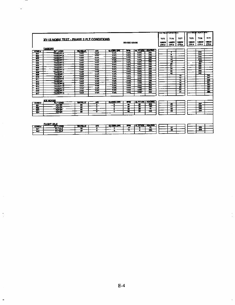
I XV lS Ntgd_l_ _ IM4A._E 2 I:LT OONI_I'N3N_
c_le$ R.'r _ IA_CB.J.JE
TAKBOFF A VAR VAIl
T_ B VAH VAIl
TAKI_31_ C VAIl VAH
6O4 TAKI_I_ D VAR VAR
TAt_BTF _ VAR .- VAR
T_ _ VAIl VAH
. ,, TAI(,EEJ_ F VAH VAR|_{_ VAH V_
TAK;BDF_ H VAR VAR
i]66_10 TAKBDFF I VAR VAR
TAK]_JPP J VAH VAR
, ' ]_ K VAH VAH612 TAIQ33FF I. VAR VAR
613 TAK_0fF M VAR VAR
614 T_ N YAH YAH
615 ]AKJJ_,.:H"Q VAH V_616 ' '_'AF4:UI'I" P VAH 'VAR
617 TAK]_FF O VAR VAR
I_/BK) _nlJ_
m.ICBL0PE _ N.11TUDE
VAFL VAR VAIqL 2r_
VA_ VAR VAK 2_6
VA_ VAR VAH.
VAFL VAR VAR 256
VAR VAR VAR
VAR VAK VAK
VAIL VAFL VAK ' 2_b
VAR VAK YAK
VAR VAIL VAR 255
VAIL '"VAR VAR
"' VAR. _ V_
_A_ VA_ WU,L
VAIL VAR VAR 2_,VAR. VAIL VIUqL
VA_ VAIL VAK
VA_ VA_ VAH.
VAK VAR VAP.
VA_ VAR VAR.
_w
I e_ L hove_ . t go I o
J'F J" I °I o I go I 2o I m I
o, 1.1o1 1
7"/ I '1ITS ?'/
"" '"c'm. |erRs, I c'm. ! c'm. cm.
? I[ I*,, •14 '1 _116 I
f8 :
12 _'" J 341
14 I Ile I ss'i_u I I aeaz'o I
L,,3_7
3_
=]
E-4


REPORT DOCUMENTATION PAGEForm ApprovedOMB No. 0704-0188
Public _porting burden for this collection of information is estimated to average 1 hour per response, including the time for reviewing instructions, searching existing data sources,
gathering and maintaining the data needed, and oc_'npleting and reviewing _ collection of information. Send comments regarding this burden estimate or any other aspect of this
collection of information, including sugga_,on$ for reducing this burden, to Washington Headquarters SeNices, Directorate for Information Operations and Reports, 1215 Jefferson Davis
Highway, Suite 1204, Arlington, VA 22202-4302, and to the Office of Management and BudgeL Paperwod_ Reduction Project (0704-0188), Washington, DC 20503.
1. AGENCY USE ONLY (h,ave blank) 2. REPORT DATE
February 1998
4. TITLE AND SUBTITLE
XV-15 Low-Noise Terminal Area Operations Testing
6. AUTHOR(S)
B. D. Edwards
7. PERFORMINGORGANIZATIONNAME(S)ANDADDRESS(ES)
Bell Helicopter Textron, Inc.P.O. Box 482
Ft. Worth, TX 76101
9. SPONSORING I MONITORING AGENCY NAME(S) AND ADDRESS(ES)
National Aeronautics and Space Administration
Langley Research Center
Hampton, VA 23681-2199
3. REPORT TYPE AND DATES COVERED
Contractor Report5. FUNDING NUMBERS
C NAS1-20094
TA 3
WU 538-07-15-10
8. PERFORMING ORGANIZATIONREPORT NUMBER
BHTI Report No. 699-099-450
10. SPONSORING/MONITORINGAGENCY REPORT NUMBER
NASA/CR-1998-206946
11. SUPPLEMENTARYNOI"ES
Langley Technical Monitor: David A. Conner
12a. DISTRIBUTION/ AVAILABIUTYSTATEMENT
Unclassified- Unlimited
Subject Category 71Distribution: Nonstandard
Availability: NASA CASI (301) 621-0390
12b. DISTRIBUTION CODE
13. ABSTRACT (Maximum 200 words)
Test procedures related to XV-15 noise tests conducted by NASA-Langley and Bell Helicopter Textron, Inc. are discussed.The tests, which took place duringOctober and November 1995, near Waxahachie, Texas, documented the noise signatureof the XV-15 tiltrotoraircraft at a wide variety of flight conditions. The stated objectives were to:
-provide a comprehensive acoustic database for NASA and U.S. Industry-validate noise prediction methodologies, and-develop and demonstrate low-noise flight profiles.
The test consisted of two distinct phases. Phase 1 provided an acoustic database for validating analytical noise predictiontechniques; Phase 2 directly measured noise contour information at a broad range of operating profiles,with emphasis on
minimizing "approach" noise.
This report is limited to a documentation of the test procedures, flight conditions, microphone locations,meteorologicalconditions, and test personnel used in the test. The acoustic results are not included.
14. SUBJECT TERMS
XV-15, tiltrotor, noise prediciton
17. SECURITY CLASSIRCATIONOF REPORT
Unclassified
18. SECURITY CLASSIFICATIONOF THIS PAGE
Unclassified
19. SECURITY CLASSIRCATIONOF ABSTRACT
15. NUMBER OF PAGES
62
16. PRICE CODE
A04
20. LIMITATION OF ABSTRACT
NSN 7540-01-280-5500 Standard Form 298 (Rev. 2-89)Prescribed by ANSI Sld. Z39-18,,)ol=. _r,,>