xyz company site survey report
TRANSCRIPT

XYZ Company
City, State
Site Survey Report
Prepared By: Technician Date: XX/XX/20XX

Page 2 of 25
OVERVIEW On Month Day, 20XX, a site survey was conducted for XYZ Company in City, State. This survey was conducted to determine the coverage area of the existing access points and antenna types installed at their respective locations in the facility.
This site survey report contains all of the required specifications to facilitate the inventory and coverage information of the XYZ Communications System to achieve the desired coverage. The report is to be used by the XYZ Company IT team to determine if there is a need to relocate existing access points, or if there is need to install additional access points for complete store coverage. The representative responsible for the content of this document is:
Name Telephone Fax Email Technician 913-XXX-0000 913-xxx-0000 [email protected]
The Circuit City representative supplying information used in this document is:
Name Telephone Fax Email Main Contact xxx-xxx-xxxx xxx-xxx-xxxx
For any questions or clarifications, please contact your local account team or the appropriate representative shown above. All Specific Site Addresses and Identifying Information: Address:
Site Name XYZ Company Site Address City, State Zip
Information: Sales/Storage Facility

Page 3 of 25
Warranty of Coverage: The site survey results reported within this document are warranted by the seller for one (1) year from the survey conclusion date to provide 100% RF coverage in the regions designated by your representative and documented within the report. This warranty applies if the enumerated equipment is installed, configured, and tested per this report. The warranty further assumes that there are no changes to the facility’s structure, variable parameters within the building that may modify the RF propagation, or the addition of other RF devices that may interfere with the installed RF equipment. Variables such as those stated above may require a diagnostic survey of the site and carry additional costs. The warranty only applies to coverage by the RF models specified within the report and reflects the device types designated on the buyer's site survey request form. This warranty is limited to RF coverage and does not provide any explicit or implied guarantee relating to other network design parameters; such as, but not limited to: optimum network speed, data throughput, fault tolerance, redundancy, etc.
Presuming that the buyer notifies the seller within the warranty period, any defect will be handled by the seller within a reasonable time frame. These steps will include arranging for and performing a new survey of the site. Should this re-survey find coverage shortfalls in the equipment specified, the seller will provide a revised site survey report and provide any labor necessary to move the existing equipment and/or install additional equipment as specified in the revised report. The buyer is responsible for the purchase of any additional equipment required. Should the re-survey find that the system was not installed in accordance with the specifications shown in the site survey report, the seller reserves the right to invoice the buyer at the current rates for the time spent in troubleshooting the installation, including the expenses incurred.
Page 4 of 25
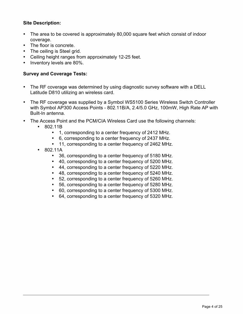
Site Description: • The area to be covered is approximately 80,000 square feet which consist of indoor
coverage. • The floor is concrete. • The ceiling is Steel grid. • Ceiling height ranges from approximately 12-25 feet. • Inventory levels are 80%. Survey and Coverage Tests: • The RF coverage was determined by using diagnostic survey software with a DELL
Latitude D810 utilizing an wireless card.
• The RF coverage was supplied by a Symbol WS5100 Series Wireless Switch Controller with Symbol AP300 Access Points - 802.11B/A, 2.4/5.0 GHz, 100mW, High Rate AP with Built-In antenna.
• The Access Point and the PCM/CIA Wireless Card use the following channels: • 802.11B
• 1, corresponding to a center frequency of 2412 MHz. • 6, corresponding to a center frequency of 2437 MHz. • 11, corresponding to a center frequency of 2462 MHz.
• 802.11A • 36, corresponding to a center frequency of 5180 MHz. • 40, corresponding to a center frequency of 5200 MHz. • 44, corresponding to a center frequency of 5220 MHz. • 48, corresponding to a center frequency of 5240 MHz. • 52, corresponding to a center frequency of 5260 MHz. • 56, corresponding to a center frequency of 5280 MHz. • 60, corresponding to a center frequency of 5300 MHz. • 64, corresponding to a center frequency of 5320 MHz.

Page 5 of 25
System Component Locations: Access Point #1: Store Room / Warehouse General Information: • AP Model: Symbol AP200 B/A 2.4/5.0 GHz, 100mW, High Rate AP with Internal
antennas. • AP Location: Mounted beneath the roof in the South West area of Store Room /
Warehouse, inverted horizontally to the ground. • Data Cabling: The Ethernet cable was installed prior to coverage tests. • Power Cabling: P.O.E. • Radio Card – 802.11B
• RF Channel: 1 at 2412MHz • MAC Address: 00:A0:F8:B5:1E:53 • ESSID: 51
• Radio Card – 802.11A • RF Channel: 36 at 5180MHz • MAC Address: 00:A0:F8: 6E:36:A0 • ESSID: 41
Mounting Information: • AP Height: The AP is approximately 25 feet from the ground. • Mounting Surface: Steel Beam

Page 6 of 25
AP 1 Signal RF Coverage Overview Channel A:
Page 7 of 25
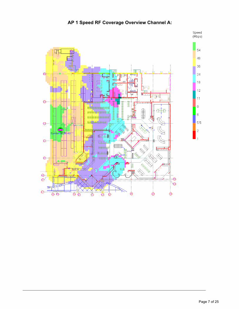
AP 1 Speed RF Coverage Overview Channel A:

Page 8 of 25
AP 1 Signal RF Coverage Overview Channel B:

Page 9 of 25
AP 1 Speed RF Coverage Overview Channel B:
Page 10 of 25
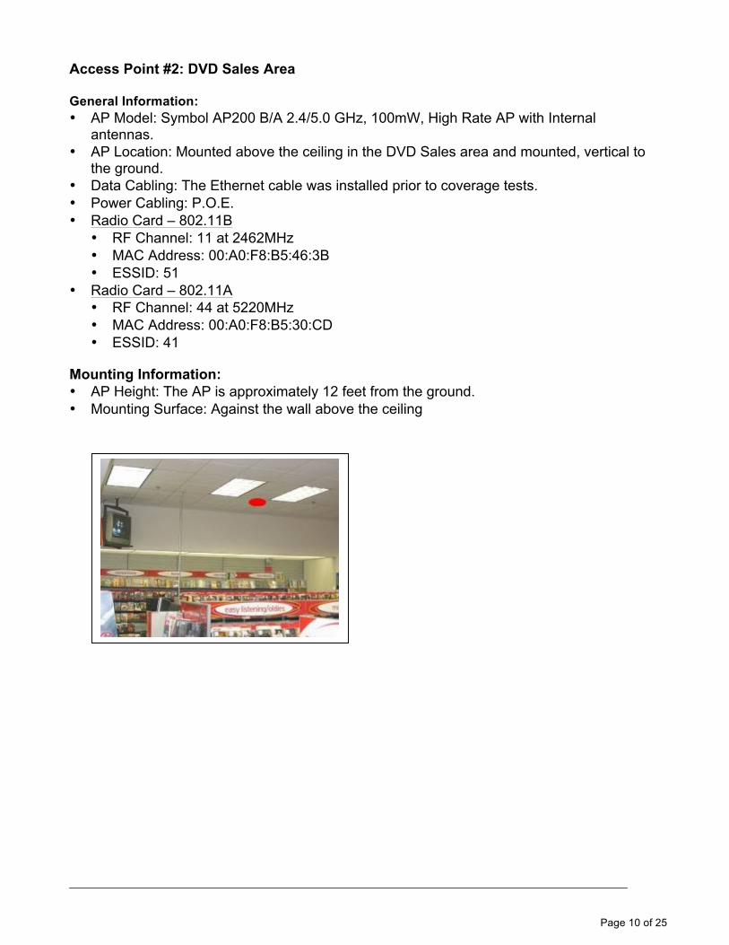
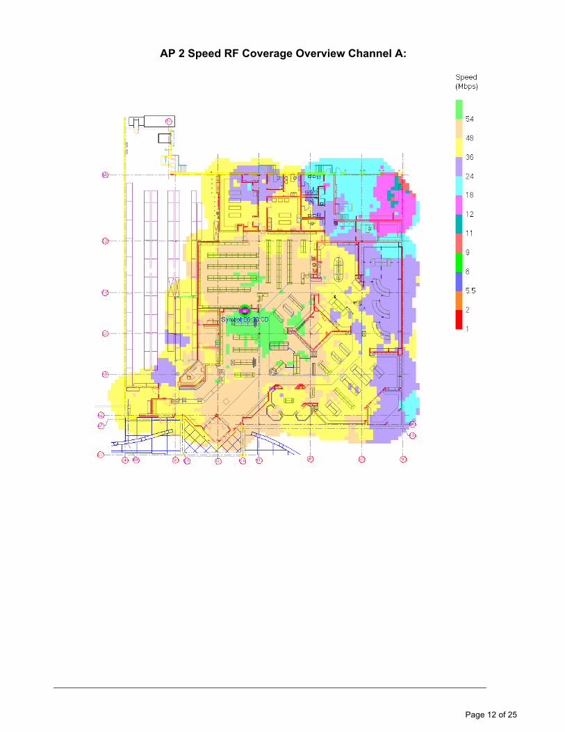
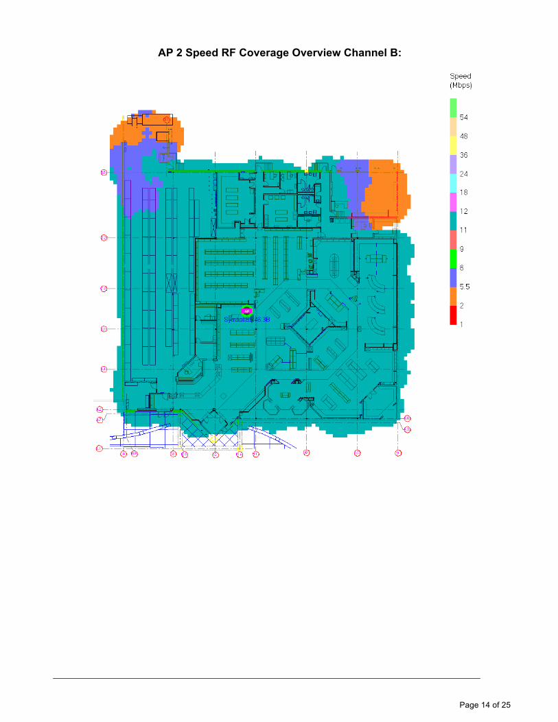
Access Point #2: DVD Sales Area General Information: • AP Model: Symbol AP200 B/A 2.4/5.0 GHz, 100mW, High Rate AP with Internal
antennas. • AP Location: Mounted above the ceiling in the DVD Sales area and mounted, vertical to
the ground. • Data Cabling: The Ethernet cable was installed prior to coverage tests. • Power Cabling: P.O.E. • Radio Card – 802.11B
• RF Channel: 11 at 2462MHz • MAC Address: 00:A0:F8:B5:46:3B • ESSID: 51
• Radio Card – 802.11A • RF Channel: 44 at 5220MHz • MAC Address: 00:A0:F8:B5:30:CD • ESSID: 41
Mounting Information: • AP Height: The AP is approximately 12 feet from the ground. • Mounting Surface: Against the wall above the ceiling
Page 11 of 25
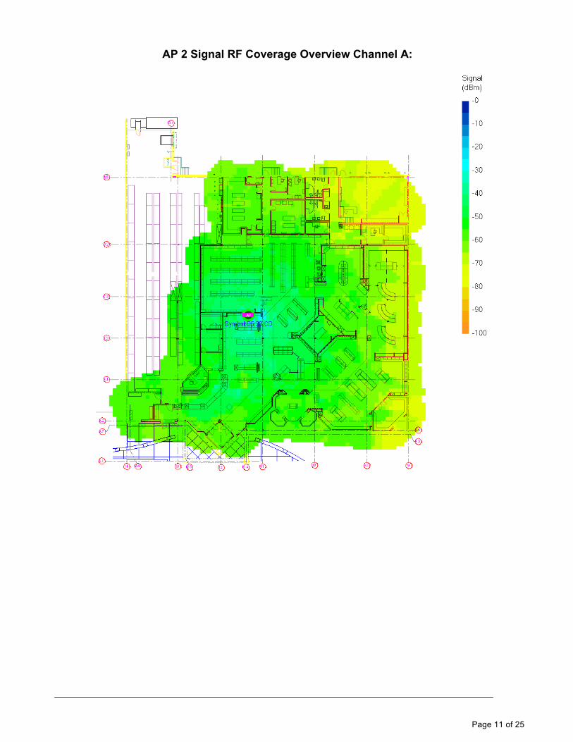
AP 2 Signal RF Coverage Overview Channel A:
Page 12 of 25
AP 2 Speed RF Coverage Overview Channel A:

Page 13 of 25
AP 2 Signal RF Coverage Overview Channel B:
Page 14 of 25
AP 2 Speed RF Coverage Overview Channel B:
Page 15 of 25
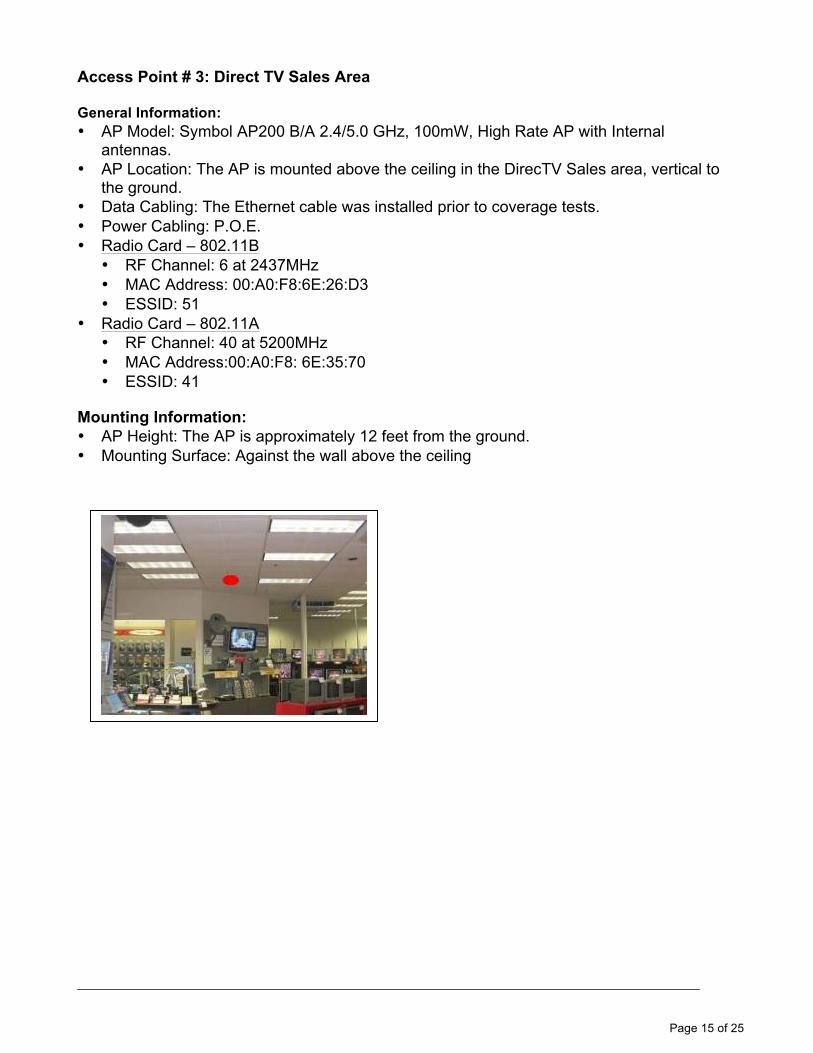
Access Point # 3: Direct TV Sales Area General Information: • AP Model: Symbol AP200 B/A 2.4/5.0 GHz, 100mW, High Rate AP with Internal
antennas. • AP Location: The AP is mounted above the ceiling in the DirecTV Sales area, vertical to
the ground. • Data Cabling: The Ethernet cable was installed prior to coverage tests. • Power Cabling: P.O.E. • Radio Card – 802.11B
• RF Channel: 6 at 2437MHz • MAC Address: 00:A0:F8:6E:26:D3 • ESSID: 51
• Radio Card – 802.11A • RF Channel: 40 at 5200MHz • MAC Address:00:A0:F8: 6E:35:70 • ESSID: 41
Mounting Information: • AP Height: The AP is approximately 12 feet from the ground. • Mounting Surface: Against the wall above the ceiling

Page 16 of 25
AP 3 Signal RF Coverage Overview Channel A:

Page 17 of 25
AP 3 Speed RF Coverage Overview Channel A:

Page 18 of 25
AP 3 Signal RF Coverage Overview Channel B:

Page 19 of 25
AP 3 Speed RF Coverage Overview Channel B:
Page 20 of 25
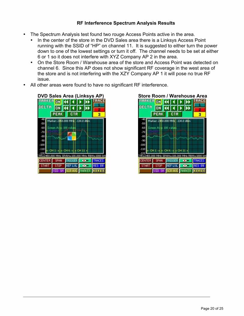
RF Interference Spectrum Analysis Results
• The Spectrum Analysis test found two rouge Access Points active in the area. • In the center of the store in the DVD Sales area there is a Linksys Access Point
running with the SSID of “HP” on channel 11. It is suggested to either turn the power down to one of the lowest settings or turn it off. The channel needs to be set at either 6 or 1 so it does not interfere with XYZ Company AP 2 in the area.
• On the Store Room / Warehouse area of the store and Access Point was detected on channel 6. Since this AP does not show significant RF coverage in the west area of the store and is not interfering with the XZY Company AP 1 it will pose no true RF issue.
• All other areas were found to have no significant RF interference.
DVD Sales Area (Linksys AP) Store Room / Warehouse Area

Page 21 of 25
Network Connections: • An ES3000 POE switch was installed in the MDF room to power AP’s 1-3. • Two WS5100 Wireless Switch Controllers are installed to be used as Primary and
Redundant. MDF Equipment List: • No additional equipment is needed for the site installation. Summary: • Surveyed the existing AP200 RF network.
• 802.11B was surveyed for 5.5Mb or better. • 802.11A was surveyed for 24Mb or better.
• After the survey the network was found to have adequate coverage. • The Spectrum Analysis test found two rouge Access Points. • Went over the coverage results with the customer contact.
Page 22 of 25
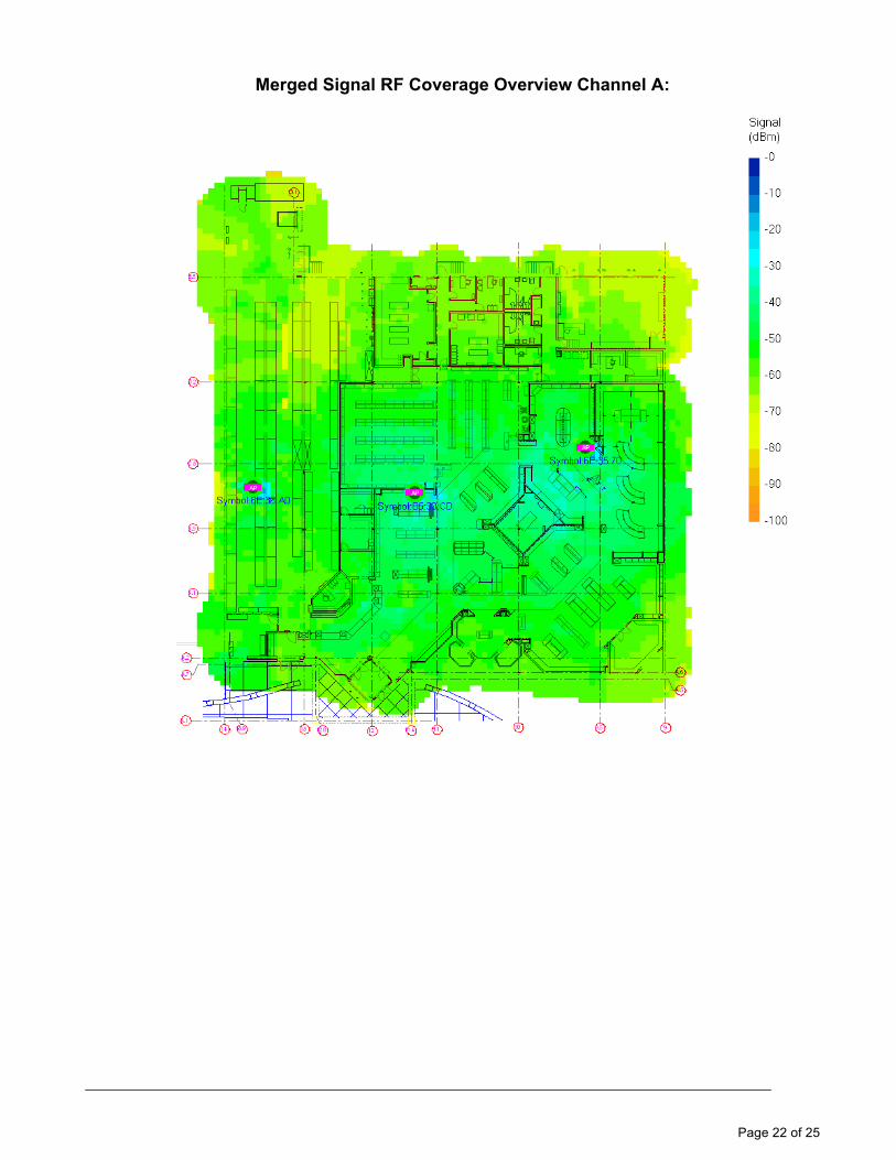
Merged Signal RF Coverage Overview Channel A:

Page 23 of 25
Merged Speed RF Coverage Overview Channel A:

Page 24 of 25
Merged Signal RF Coverage Overview Channel B:
Page 25 of 25
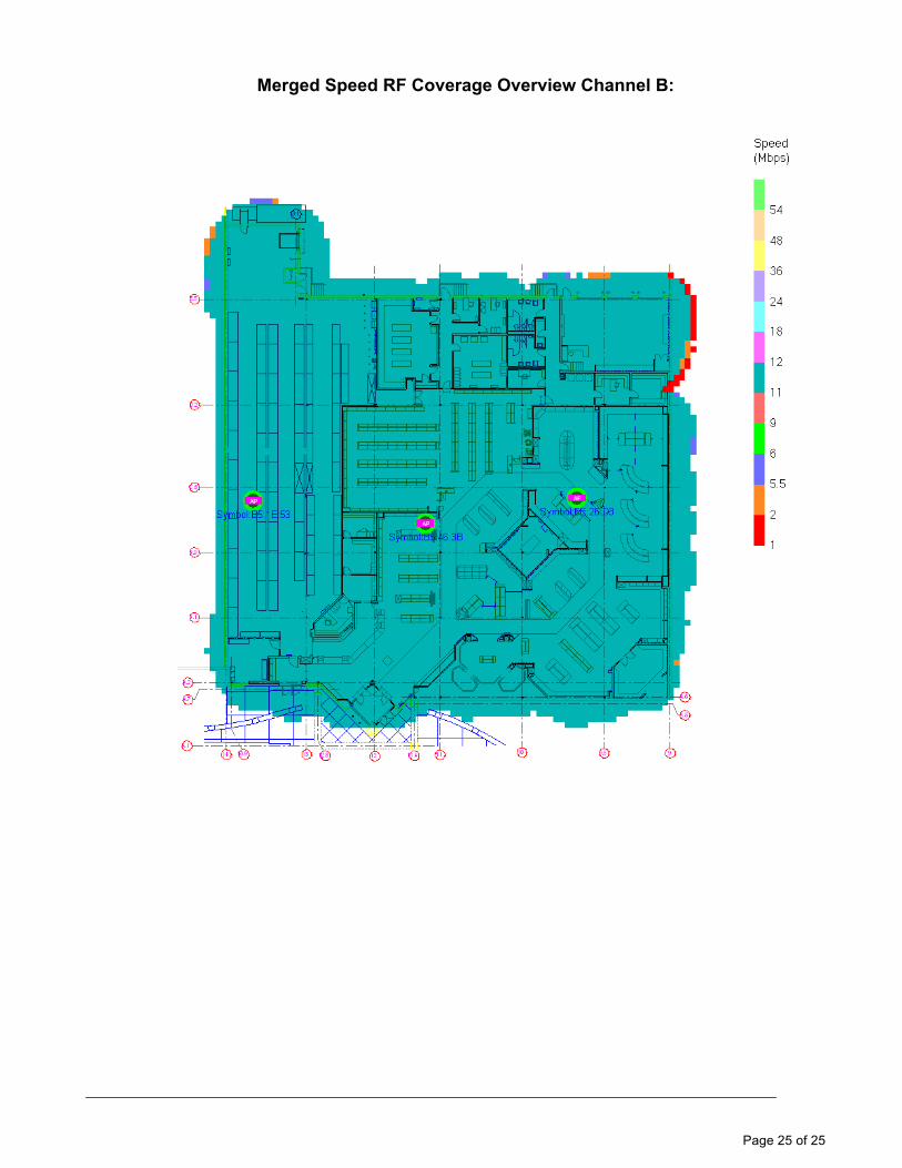
Merged Speed RF Coverage Overview Channel B: