y2e2 – hvac sequence of operation (controls) · hvac systems at y2e2 cee 243 control basics...
TRANSCRIPT

Copyright 2011
HVAC Systems at Y2E2
CEE 243
Y2E2 – HVAC sequence of operation
(controls)
James O’Donnell

Copyright 2011
HVAC Systems at Y2E2
CEE 243
What we will learn today?
• Basics of controls
• Control sequences for each subsystem at
Y2E2
• Resources for Y2E2
– Mechanical Equipment pdf
2

Copyright 2011
HVAC Systems at Y2E2
CEE 243
Control basics
• Typically components have a setpoint, i.e., operating functional objective,
• Under computer control, the HVAC system uses active components to maintain the setpoint.
• Active components can be regulated by the control system (e.g., damper 0 – 100% open)
• Rules “tell” control system how to reach setpoint.
• Control system has input sensors and output control signals
– control signals regulate the active components
3

Copyright 2011
HVAC Systems at Y2E2
CEE 243
Simple control example – Active beam
4
constant
75 F
71 F
Assume system setpoint temp = 73 F
Occupied and unoccupied setpoint
Setpoint user adjustable by +/- 3 F
Deadband of +/- 2 F
User override lasts 2 hours
Point # 6370001
Description Space air temp
Setpoint –
Occupied
73
Setpoint –
Unoccupied
68
Deadband +- 2 F
Units O F
Zone Room #
System AHU-1, 2 or 3
User
adjustable?
+- 3 F

Copyright 2011
HVAC Systems at Y2E2
CEE 243
Deadband control
5
0
20
40
60
80
100
120
0
100
200
300
400
500
600
700
800
900
1000
65 66 67 68 69 70 71 72 73 74 75 76 77 78 79 80 81 82 83 84 85
Va
lve
Po
sit
ion
pe
rce
nt
Air
flo
w C
FM
Temperature deg F
Air Flow
Cooling Valve
Heating Valve
DEAD
BAND
Setpoint

Copyright 2011
HVAC Systems at Y2E2
CEE 243
Active beams
• Active components: Cold and hot water valves, air flow damper
• Temperature control– Occupied temperature setpoint is adjustable by the user +/- 3F
– Unoccupied setpoints cooling: 78F heating: 65F
– Control cold and/or hot water valve of active beam to achieve temperature setpoint
– Temperature deadband of +/- 2F
– User override button to extend occupied hours by 2 hours
• Air flow control– Air flow is constant (on during occupied hours (basement 24/7),
off during unoccupied hours)
– CAV boxes modulate flow to achieve constant air flow during occupied hours only, except during night setback and warmup(compensating for different air pressures)
6

Copyright 2011
HVAC Systems at Y2E2
CEE 243
Space with radiators
7

Copyright 2011
HVAC Systems at Y2E2
CEE 243
Baseboard radiators
• Active components: hot water control valve
• Temperature control– Occupied temperature setpoint is adjustable by
the user +/- 3F
– Unoccupied temperature setpoints heating: 65F
– Control hot water valve of baseboard heater to achieve temperature setpoint
– If outside air temperature is above 78F close valve at all times
– User override button to extend occupied hours by 2 hours
8

Copyright 2011
HVAC Systems at Y2E2
CEE 243
Conference rooms
• Active beam control as in other rooms
• Active component: inline supply fan
• Additionally CO2 level control
– If CO2 concentration exceeds max CO2
setpoint, turn on inline supply fan
– Max CO2 setpoint is 500 ppm above outside
air CO2 concentration
9

Copyright 2011
HVAC Systems at Y2E2
CEE 243
Laboratories
• Active components: damper, water coil valves
• Air flow control
– The greater of:• The required air changes (6 ac/hr)
• Proper amount needed for cooling
• Sufficient makeup air for fume hoods (supply ~ exhaust)
– For heating air flow is set to minimum
– For cooling air flow is set to maximum
• Temperature control
– +/- 2F deadband
10

Copyright 2011
HVAC Systems at Y2E2
CEE 243
Radiant floor
11

Copyright 2011
HVAC Systems at Y2E2
CEE 243
Radiant floor
• Active components: Pump and valve
• Off if outside air temperature > 78F
• Otherwise– Turn on pump
– To reach steady state:• Increase valve position by 10% (every 10 min) until
temperature setpoint of 71F is met
• Decrease valve position by 5% (every 10 min) until temperature setpoint of 71F is met
– After reaching steady state• Adjust valve position by 1% (every 10 min) only
• During unoccupied hours setpoint = 66F
12

Copyright 2011
HVAC Systems at Y2E2
CEE 243
Fan Coil Units
13

Copyright 2011
HVAC Systems at Y2E2
CEE 243
Fan coil units
• Active components: chilled water control valve
• On 24/7
• Temperature control:
– Modulate chilled water valve to achieve temperature setpoint if space temperature is above setpoint
– If two spaces are controlled by one unit, use higher temperature
14

Copyright 2011
HVAC Systems at Y2E2
CEE 243
Main chilled water loop
Serves:
• Tempered water loop
• Cooling coils
(AHUs, FC, CVs,
VAVs)
• Server Rack
15

Copyright 2011
HVAC Systems at Y2E2
CEE 243
Chilled water system
• Active components: Control valve and booster pump
• Normal operation: Valve is used to control differential pressure to setpoint (if not enough booster pump helps out)
• If water return temp < 58F (for > 5 min) reset down differential pressure setpoint
• If water return temp < 55F (for > 5 min), start pump and recirculate water– If water supply temp < 48F go back to normal
16

Copyright 2011
HVAC Systems at Y2E2
CEE 243
Tempered chilled water loop
Serves:
• Active beams
17

Copyright 2011
HVAC Systems at Y2E2
CEE 243
Tempered chilled water system
• Active components: Two pumps
• On/off speed control– Lead/lag operation (weekly)
– Pumps are controlled to meet differential pressure setpoint • lead pumps first
• If pressure difference to small lag pump starts in addition
• If both are running slow (< 25Hz), turn off lag pump
– Pumps should be off during unoccupied hours (expect overrides)
• Temperature control– Maintain supply water temperature at 60F by opening and closing
control valve
• Supply Temp Reset (to prevent condensation on active beams)– If outside dewpoint temperature > 58F
-> supply temperature setpoint = dewpoint temperature + 2F
18

Copyright 2011
HVAC Systems at Y2E2
CEE 243
Main hot water loop
Serves:
• Tempered water loop
• Heating coils (AHU + CVs)
• Radiators19

Copyright 2011
HVAC Systems at Y2E2
CEE 243
Hot water system
• Active components: Two pumps, heat exchanger valve
• On/Off speed control– Same as for tempered chilled water system
– If no hot water is needed close heat exchanger valve
• Temperature control– Maintain supply water temperature at 180F by
opening and closing value 1 (1/3 of flow) and valve 2 (2/3 of flow)
20

Copyright 2011
HVAC Systems at Y2E2
CEE 243
Tempered hot water loop
Serves:
• Active beams
• Radiant slab
• Heating coils (VAVs)
21

Copyright 2011
HVAC Systems at Y2E2
CEE 243
Tempered hot water system
• Active components: Two pumps, valve
• On/Off speed control
– Same as for hot water system
• Temperature control
– Maintain supply water temperature at 110F
by opening and closing value
22

Copyright 2011
HVAC Systems at Y2E2
CEE 243
Air handling unit
23

Copyright 2011
HVAC Systems at Y2E2
CEE 243
Air Handling Units (1)
• Active components: fans, heating and cooling coil water valve, heat recovery bypass valve, cooling coil bypass valve
• 24/7 because of labs in the basement
• Maintain total pressure setpoint by modulating fan speed
• Supply air to be maintained at 65F (max DewPoint 60F)
• Cooling, Heating, Dehumidification, Morning Warm-up
24

Copyright 2011
HVAC Systems at Y2E2
CEE 243
Air Handling Units (2) - cooling
• Active components: heat recovery bypass damper, cooling coil bypass damper, cooling coil valve
• Heat recovery– If outside air temperature > exhaust air temperture -> heat
recovery bypass damper closed (heat recovery “on”) otherwise open
– Heat recovery bypass damper modulates to set supply air temperature to setpoint
• Cooling– If no heating and supply air temperature > setpoint
-> cooling coil bypass damper closed and cooling coil valve modulates to achieve setpoint
– If no heating and supply air temperature < setpoint-> first close valve then close bypass damper
25

Copyright 2011
HVAC Systems at Y2E2
CEE 243
Air Handling Units (3) - heating
• Active components: heat recovery bypass damper, cooling coil bypass damper, cooling coil valve
• Heat recovery– If outside air temperature < heat recovery leaving temperature
& exhaust air temperature > heat recovery leaving temperature -> heat recovery bypass damper closed (heat recovery “on”) otherwise open
– Heat recovery bypass damper modulates to set supply air temperature to setpoint
• Heating– If no cooling and supply air temperature < setpoint
-> heating coil bypass damper closed and heating coil valve modulates to achieve setpoint
– If no cooling and supply air temperature > setpoint-> first close valve then close bypass damper
26

Copyright 2011
HVAC Systems at Y2E2
CEE 243
Air Handling Units (4) - dehumidification
• If leaving air dewpoint temperature > 60 F
then achieve dewpoint setpoint in addition
to temperature setpoint with additional
heating to lower moisture content in air
27

Copyright 2011
HVAC Systems at Y2E2
CEE 243
Air Handling Units (5) – Morning warmup
• Only if daytime temperature does not
exceed 68F
– 2-6 am air supply temperature setpoint is set
to 69F
– After 6am everything is set to normal
– Mardyke example
28

Copyright 2011
HVAC Systems at Y2E2
CEE 243
Exhaust fans
• Functional Intent?
• Flow Rate 7500 cfm
• Possible Energy Conservation Measures
(ECM)?
29

Copyright 2011
HVAC Systems at Y2E2
CEE 243
Mechanical ventilation
30

Copyright 2011
HVAC Systems at Y2E2
CEE 243
Building pressurization control
• Basement:
– Labs: Negative pressure: 5-10% more
exhaust air than supply
– Offices: Positive pressure: 5-10% more
supply air than exhaust
• Above Grade levels:
– If static pressure rises above 0.03” w.c. atria
dampers open to keep pressure below 0.03”
31

Copyright 2011
HVAC Systems at Y2E2
CEE 243
Natural ventilation
32

Copyright 2011
HVAC Systems at Y2E2
CEE 243
Natural ventilation
• Active components: Operable windows, atria damper
• Initial range for natural ventilation outside air temperature 68 – 85F
• If outdoor temperature is within range & average space temperature > 70F -> open dampers– For each zone where temperature > 70F open operable windows
– If zone temperature < 70F for at least 5 min close windows again
– If all windows around one atrium are closed also close corresponding atrium damper
• Night purge (if daytime outside air temperature exceeds 75F)– During unoccupied hours open windows if
• Outside air temperature < 65F and space temperature > 65F
– Close windows if space temperature < 63F
33
Copyright 2011
HVAC Systems at Y2E2
CEE 243
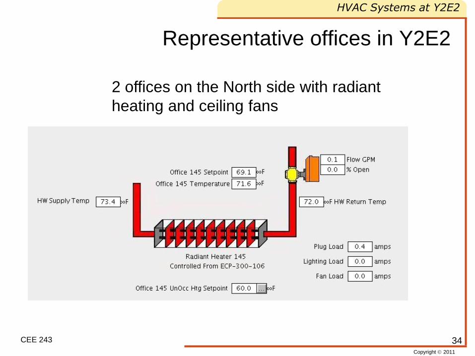
Representative offices in Y2E2
2 offices on the North side with radiant
heating and ceiling fans
34

Copyright 2011
HVAC Systems at Y2E2
CEE 243
Representative offices in Y2E2
2 offices on the South side with active
beams (heating and cooling)
35

Copyright 2011
HVAC Systems at Y2E2
CEE 243
Other Measurements
• Weather
• PV
• Electrical Sub-meters
36

Copyright 2011
HVAC Systems at Y2E2
CEE 243
Electricity
37

Copyright 2011
HVAC Systems at Y2E2
CEE 243
Reading Material
• Summary of Performance Analyses of a
Santa Clara County Facility by CEE 243
Student Groups
• LEED Report by Turner and Frankel
38

Copyright 2011
HVAC Systems at Y2E2
CEE 243
Homework
• Compare patterns between different
years (2008,2009,2010)
• Classify pattern (red/yellow/green) re
assumed functional intent
39
Copyright 2011
HVAC Systems at Y2E2
CEE 243
Conclusions
• Basic Control overview for Y2E2.
• Reference data manual for more detail
• Questions?
40